Embed Size (px)
Citation preview

Round Shaft SystemsInch Series


Expertise in linear motion.
For over 40 years INA has contributed to developments inlinear technology. The results speak for themselves: ourrange of linear guidance systems is very comprehensive inscope, and we have the right linear guidance system forevery application as well as a wide variety of useful acces-sories.
We also maintain an open and honest relationship withour customers by working with them consistently and com-petently - from the initial design concept right down to thedelivery of the finished product. And we believe that pro-viding expert advice on user applications and respondingto customer requirements is an important part of our job.
In our line of shaft guidance systems you won't find any"one-size-fits-all" products. We also offer special designsfor maximum load carrying capacity including opendesigns for support rails.
An extensive range of accessories supplements thesedesigns, and together they form a versatile modular sys-tem that includes shaft support blocks, guideways, andprecision shafts. And these products are tailor made. Atour linear quick centers around the world we can machineshaft ends individually to meet the most demanding cus-tomer specifications: threaded or stepped, with radial oraxial bores, with or without threads... you name it. Thecomponents you receive are ready to install.
Our modular system thus gives you plenty of options whenplanning your own personal design solutions. Of course,you can also get all our shaft guidance systems as com-plete ready-to-install units. Whatever the case, the mostimportant thing for us is that you are fully satisfied withour product.
Schaeffler Group USA Inc.Fort Mill, South Carolina 29715
KKXXKKBBZZ RRoouunndd SShhaafftt SSyysstteemmss
MAX3 is a registered trademark of Schaeffler Group USA Inc.

2
Contents
Product Description 5
Calculations 6
Design & Installation 8
KX 10MAX3 Self-Aligning Linear Ball Bearing
KXO 10MAX3 Self-Aligning Linear Ball Bearing, Open
KGX 12MAX3 Self-Aligning Linear Ball Bearing With Housing
KGXO 12MAX3 Self-Aligning Linear Ball Bearing With Housing, Open
KTX 14MAX3 Tandem Linear Ball Bearing With Housing
KTXO 14MAX3 Tandem Linear Ball Bearing With Housing, Open
KBZ 16Precision Linear Ball Bearing
KBZ..OP 16Precision Linear Ball Bearing, Open
KGBZ 17Precision Linear Ball Bearing With Housing
KGBZ..OP 17Precision Linear Ball Bearing With Housing, Open
KNZ 18Self-Aligning Linear Ball Bearing
KNZ..OP 18Self-Aligning Linear Ball Bearing, Open
KGNZ 19Self Aligning Linear Ball Bearing With Housing
KGNZ..OP 19Self-Aligning Linear Ball Bearing With Housing, Open
KTNZ 20Tandem Linear Ball Bearing With Housing
KTNZ..OP 20Tandem Linear Ball Bearing With Housing, Open
Schaeffler Group Industrial

3
WZ 21Precision Hardened & Ground Shafting - Class L, S
WZ..PDT 21Predrilled & Tapped Hardened & Ground Shafting - Class L, S
TSWZ 23Shaft Support Rails
TSWZ..PD/TSWWZ 23Shaft Support Rails & Assemblies Drilled To Standard Dimensions
TSUZ 23Shaft Support Rails, Low Profile
TSUZ..PD 23Shaft Support Rails, Low Profile, Drilled To Standard Dimensions
GWZ 24Shaft End Support Blocks
Sales Offices
Schaeffler Group Industrial

4 Schaeffler Group Industrial

5
Product Descriptions
Series KGX/KGNZSelf-Aligning Linear Ball Bearings With HousingsSeries KGX..PP/KGNZ..PP mounted units are manufactured of ahigh-strength aluminum alloy, and are supplied with a seriesKX/KNZ linear bearing sealed on both ends.
Series KGXO..PP/KGNZ..OP PP mounted units are supplied with aSeries KNZ..OP bearing sealed on both ends for use with support-ed shafts.
Series KTX/KTNZSelf-Aligning Tandem Linear Ball Bearings With HousingsSeries KTX..PP/KTNZ..PP and KTXO..PP/KTNZ..OP PP mountedunits are similar to the mounted units described above(KGX..PP/KGNZ..PP and KGXO..PP/KGNZ..OP PP) but are suppliedwith a longer housing and (2) KX..PP/KNZ..PP or (2)KXO..PP/KNZ..OP PP bearings installed in tandem within thehousing.
Series WZ - Precision ShaftsLinear shafts of series WZ are manufactured to the most precisestandards which meet or exceed all industry standards (ABMA).Series WZ shafts are manufactured from a high strength steel, AISI1055 (Cf53). They are hardened (670 840HV) and ground to preci-sion roundness, straightness and surfaces finish specifications.Refer to dimension table on page 21.
INA Linear shafts are available in lengths up to 17' (5.18m)depending on the diameter. The shafts can be supplied cut tolength and chamfered, or machined to your drawing includingjournals, threaded diameters, etc. If longer lengths are neededplease inquire with INA Linear Engineering.
Series TSWZ/TSUZ - Shaft Support RailsSeries TSWZ shaft support rails are manufactured from a high-strength aluminum alloy and are available in four foot lengths. Therails can be mounted in tandem for long-length applications.Series TSWZ..PD are supplied with drilled-through holes to stan-dard dimensions for mounting the shaft and mounting rail to abase.
Preassembled shaft and support rail are available for ease of han-dling and installation. Shaft is Class L, hardened and ground steeland support rail is high strength aluminum alloy.
Series TSUZ and TSUZ..PD are similar to series TSWZ and TSWZ..PDfor those applications requiring a lower height centerline to base.
Series GWZ - Shaft End Support BlocksConstructed of high strength aluminum alloy for shaft sizes 1/4” to2” in diameter.
INA Linear ball bearings of series KX MAX3, KBZ, KNZ are recircu-lating linear ball bearings which are designed to provide the fol-lowing features:
❏ Low friction❏ High rigidity❏ High accuracy❏ Light weight❏ Low noise
Linear ball bearings of series KX MAX3, KBZ, KNZ are available ina variety of designs and sizes.
Series KX MAX3 / KNZ- Self-Aligning Linear Ball BearingsLinear ball bearings of series KX/ KNZ.. consist of a precisionmolded retainer of a high strength engineered resin and hardenedand ground bearing races. Series KXO/KNZ..OP.. bearings have asegment removed for applications requiring supported shafts.
The KX MAX3/KNZ series offers:❏ Ground races for smoothest operation❏ Self-aligning in any housing❏ Interchangeable with other standard makes❏ Lower noise level❏ Lighter weight❏ Cost effective bearing for round shaft rails
In addition, the KX MAX3 series offers:❏ Larger load capability due to increased number of ball rows❏ Greater misalignment capability❏ Longer bearing life due to internal lubrication reservoirs❏ Double lip seal floats with the shaft
KBZ Series - Precision Linear Ball BearingsLinear ball bearings of series KBZ and KBZ..OP consist of a hard-ened and ground solid outer ring and a retainer. The outer ring ismachined from high-carbon bearing steel. The retainer is manufac-tured from a high strength engineered resin. Series KBZ..OP have asegment removed from the outer ring for applications with sup-ported shafts.
Schaeffler Group Industrial

6
Calculations
Load carrying capacity and operating lifeThe selection of a linear ball bearing size depends on the require-ments in terms of load carrying capacity, operating life and relia-bility in operation. When calculating the bearing life, the basicload ratings are used as a measure. The dynamic load ratingapplies to moving bearings as compared to applications wheremotion does not occur or occurs only very infrequently.
Operating lifeThe basic rating life for linear ball bearings is calculated as fol-lows:
or with the help of the graph on the following page.
L (inches)Basic rating life reached or exceeded by 90% of a sufficiently large groupof apparently identical bearings before the first evidence of materialfatigue develops.
C (Lbs)Basic dynamic load rating
P (Lbs)Equivalent bearing load
NOTE: Rated life expectancy and load ratings are based on conditionswhich require a shaft with a surface hardness of HRC 59 minimum.
Load safety factorFor linear ball bearings which are subject to static or shock loads,the load safety factor in terms of permissible deformation of thebearing at the ball contact points, and is defined as follows:
S0 (—)
Load safety factor
C0 (Lbs)Basic static load rating
F (Lbs)Maximum bearing load
For bearing arrangements with high requirements for accuracy andsmooth running, the values for S should not be less than 3.
Influences on the load carrying capacityThe basic load ratings given in the dimension tables apply undercertain predefined conditions regarding raceway hardness, loaddirection and guidance accuracy. Other operating conditions mustbe evaluated using corresponding correction factors.
If shafts with a surface hardness lower than 59 HRC are used, thenthe basic load rating must be corrected according to the equationsbelow:
CH (Lbs)Effective dynamic load rating
fH (—)Dynamic hardness factor according to Figure 1
C (Lbs)Basic dynamic load rating
C0H (Lbs)Effective static load rating
fH0 (—)Static hardness factor according to Figure 1
C0 (Lbs)Basic static load rating
L = x 2 x 10⁶ (inches)C
P( ) 3
S0 =C0
F
CH = fH • C
C0H = fH0 • C0
Figure 1 Raceway Hardness Factors 1)converted per DIN 50 150
Schaeffler Group Industrial

7
Calculations
Load DirectionThe effective load rating of a linear ball bearing is dependent uponthe orientation of the ball rows with respect to the load direction.
The load ratings in the dimension tables are indicative of the mini-mum load rating orientation (load case I for KNZ.., KBZ.. and loadcase II for KNZ..OP, KBZ..OP see Figure 2).
If the bearing orientation changes, the effective load rating can becalculated with the following formula:
CW (Lbs)
Effective dynamic load rating
fsDynamic load direction factor (Table 1)
C0W (Lbs)
Effective static load rating
f0sStatic load direction factor (Table 1)
CW = fs • C
C0W = f0s • C0
Main load direction
Main load direction
Main load direction
Main load direction
Main load direction
Main load direction
Main load direction
Main load direction
Main load direction
Main load direction
Figure 2 Load Cases
Theoretical Life
Part Number Load Cases
fsIII f0sIII fsIV f0sIV fsV f0sV fsVI f0sVI fsVIII f0sVIII fsIX f0sIX fsX f0sX
KBZ / KNZ 04, 06, 08, KBZ10 1.15 1.4KNZ10, KBZ12 1.2 1.45KNZ 12, KBZ / KNZ 16, 20, 24, 32 1.05 1.3KBZ / KNZ 08OP, KBZ10OP 0.87 0.87 0.81 1KNZ10OP, KBZ12OP 1 1.05 0.4 0.35KNZ12OP, KBZ / KNZ 16OP, 20OP, 24OP, 32OP 1.05 1.15 0.6 0.6KX08 0.79 0.79KX10, 12, 16, 20, 24, 32 0.89 0.82KXO08 0.6 0.48KXO10, 12, 16, 20, 24, 32 0.93 0.83KXO08 0.66 0.66KXO10, 12, 16, 20, 24, 32 0.38 0.35
Table 1 • LOAD DIRECTION FACTORS
Schaeffler Group Industrial

8
Design & Installation
LubricationProper lubrication is an important prerequisite for long service lifeof any anti-friction bearing.
For non-sealed bearings oil lubrication is preferred in order toguarantee adequate lubrication of all rolling contact areas and towash away contaminants if necessary.
Grease lubrication is also possible, providing economic advan-tages as compared to oil lubrication. Greases to NLGI 3 are recom-mended. To ensure that adequate lubrication of the rolling ele-ments is provided refer to INA recommendations in Figure 3.
Operating dataLinear ball bearings of series KBZ, KNZ can withstand accelerationup to 50m/sec2 (5g) and speeds of 4m/s (13ft./sec).
The ball bearing series KX can withstand the same accelerationbut speeds up to 5m/sec.
Continuous operating temperatures of -20°C (-4°F) to+80°C (+176°F) are permissible.
Installation Assembly and location of linear ball bearings KBZ, KNZ. Thesebearings are easy to install. Smaller bearings can be pushed intotheir housing bores by hand, but for larger bearings, it is advisableto use a fitting arbor as shown on Figure 4. Housing bores shouldbe chamfered.
Figure 3 Required Lubricant Viscosity For KBZ, KNZ Bearings
Figure 4 Assembly Of Linear Ball BearingsSeries KBZ, KNZ
Schaeffler Group Industrial

9
Design & Installation
Axial location of closed linear ball bearingsBearings of series KX, KBZ, KNZ are installed with a clearance fitand should be axially located. The simplest method of location iswith the use of retaining rings as shown in Figure 5.
Axial and rotary location of linear ball bearingsLinear ball bearings of series KXO.., KBZ..OP, KNZ..OP must belocated against axial and rotary displacement.
If set screws are used, they should be secured by adhesive to pre-vent rotation.
Operating clearance and its adjustmentDepending on the bearing design, the desired operating clearanceof a bearing arrangement can be achieved either by adjusting thebearing enveloping circle or by matching the bearing to suitablehousing and/or shaft diameters.
An appropriate clearance between the bearing and the shaft isrequired for operation. The proper clearance is obtained when thebearings are mounted with our shafts Class L and housing dimen-sions in shown in the Mounting Dimensions table below.
Figure 5 Series KNZ Linear Ball Bearings - Possible Methods Of Axial Location
MOUNTING DIMENSIONS
INAPart Number
Sealsuffix
Mounting Dimensions
INA Part Number
Sealsuffix
Mounting Dimensions
Normal fit Press fit
Housingbore
Tol.-.0000Housing bore
Tol.-.0000
Housingbore
Tol.-.0000
KBZ 04 PP 0.5000 +.0005 0.4990 +.0005 KNZ 04 PP 0.5000 +.0007KBZ 06 PP 0.6250 +.0005 0.6240 +.0005 KNZ 06 PP 0.6250 +.0007KBZ 08 PP 0.8750 +.0005 0.8740 +.0005 KX / KNZ 08 PP 0.8750 +.0008KBZ 10 PP 1.1250 +.0005 1.1240 +.0005 KX / KNZ 10 PP 1.1250 +.0008KBZ 12 PP 1.2500 +.0005 1.2490 +.0005 KX / KNZ 12 PP 1.2500 +.0010KBZ 16 PP 1.5625 +.0005 1.5615 +.0005 KX / KNZ 16 PP 1.5625 +.0010KBZ 20 PP 2.0000 +.0010 1.9983 +.0010 KX / KNZ 20 PP 2.0000 +.0012KBZ 24 PP 2.3750 +.0010 2.3733 +.0010 KX / KNZ 24 PP 2.3750 +.0012KBZ 32 PP 3.0000 +.0010 2.9982 +.0010 KX / KNZ 32 PP 3.0000 +.0012
Schaeffler Group Industrial

10
MAX3 Self-AligningLinear Ball BearingSeries KX, KX..PPSeries KXO, KXO..PP• MAX3 Maximum Performance• Closed and open• With gap seal or floating contact seal on both sides
KX, KX..PP
ShaftDia.
PartNumber1)
Wt.lbs.
Dimensions in inches
d D C
1/2 KX 08 0.11 0.500 -0.0005 0.875 1.250 -0.020
KXO 08 0.066 0.500 -0.0005 0.875 1.250 -0.020
5/8 KX 10 0.183 0.625 -0.0005 1.125 1.500 -0.020
KXO 10 0.183 0.625 -0.0005 1.125 1.500 -0.020
3/4 KX12 0.243 0.750 -0.0005 1.250 1.625 -0.020
KXO 12 0.243 0.750 -0.0005 1.250 1.625 -0.020
1 KX 16 0.243 1.000 -0.0005 1.563 2.250 -0.020
KXO 16 0.243 1.000 -0.0005 1.563 2.250 -0.020
1 1/4 KX 20 0.419 1.250 -0.0006 2.000 2.625 -0.025
KXO 20 0.419 1.250 -0.0006 2.000 2.625 -0.025
1 1/2 KX 24 0.661 1.500 -0.0006 2.375 3.000 -0.030
KXO 24 0.661 1.500 -0.0006 2.375 3.000 -0.030
2 KX 32 1.235 2.000 -0.0008 3.000 4.000 -0.040
KXO 32 0.992 2.000 -0.0008 3.000 4.000 -0.040
1) Linear ball bearings sealed on both sides: suffix “PP”2) Load ratings apply only for hardened (670 to 840 HV) and ground shaft raceways.3) Load rating in main load direction4) Load ratings to ISO/C 14 728-1 (maximum values)
Misalignment compensation ±40'
Schaeffler Group Industrial

11
KXO, KXO..PP
Mounting DimensionNumber of ball
rows
Load Ratings2) 4) (lbs) Accessories
D1 C7 C1 deg.d1 t S
Dyn.C0
StaticC0
Suitable Snap Rings Shaft Diameter
0.821 0.046 1.032-0.020 - - - - 6 275 200 DIN 471 22x1.2 1/2- - 1.032-0.020 60 0.136 - 0.625 4 2603) 1903) DIN 471 22x1.2
1.059 0.056 1.112-0.020 - - - - 10 290 260 DIN 471 30x1.5 5/8- - 1.112-0.020 60 0.105 0.039 0.125 8 2903) 2603) DIN 471 30x1.5
1.176 0.056 1.272-0.020 - - - - 10 430 370 DIN 471 33x1.5 3/4- - 1.272-0.020 60 0.136 0.059 0.125 8 4303) 3703) DIN 471 33x1.5
1.469 0.068 1.886-0.020 - - - - 10 810 720 DIN 471 41x1.75 1- - 1.886-0.020 64 0.136 0.047 0.125 8 8103) 7203) DIN 471 41x1.75
1.886 0.068 2.011-0.025 - - - - 10 1490 1190 SHR-193 1.938x.125 11/4- - 2.011-0.025 64 0.201 0.090 0.188 8 14903) 11903) SHR-193 1.938x.125
2.239 0.086 2.422-0.030 - - - - 10 2090 1550 DIN 471 62x2 11/2- - 2.422-0.030 64 0.201 0.090 0.188 8 20903) 15503) DIN 471 62x2
2.838 0.103 3.206-0.040 - - - - 10 3500 2750 DIN 471 78x2.5 2- - 3.206-0.040 60 0.265 0.090 0.312 8 35003) 27503) DIN 471 78x2.5
KXO, KXO..PP Main Load Direction 4)
Location Holes
KXO 08 KXO 10 KXO 12-32
Schaeffler Group Industrial

12
MAX3 Self-AligningLinear Ball BearingWith HousingSeries KGX, KGX..PPSeries KGXO, KGXO..PP• MAX3 Maximum Performance• Closed and open• Linear ball bearing with gap seal or floating contact seal
on both sides
KGX, KGX..PP
1) Linear ball bearings sealed on both sides: suffix “PP”2) Load ratings apply only for hardened (670 to 840 HV) and ground shaft raceways.3) Load rating in main load direction4) Load ratings to ISO/C 14 728-1 (maximum values)
Shaft Diameter Part Number 1) Part Number 1) Weightlbs
Dimensions Mounting Dimensions
d A C1 H A4
A5
±.001A6 A7
1/2 KGX 08 KGX 08 PP 0.249 0.500 2.000 1.688 1.250 1.375 1.000 - - KGXO 08 KGXO 08 PP 0.216 0.500 2.000 1.500 1.100 - 1.000 0.688 0.905
5/8 KGX 10 KGX 10 PP 0.464 0.625 2.500 1.938 1.625 1.750 1.250 - -KGXO 10 KGXO 10 PP 0.395 0.625 2.500 1.750 1.375 - 1.250 0.875 1.095
3/4 KGX 12 KGX 12 PP 0.581 0.750 2.750 2.063 1.750 1.875 1.375 - -KGXO 12 KGXO 12 PP 0.495 0.750 2.750 1.875 1.535 - 1.375 0.937 1.161
1 KGX 16 KGX 16 PP 1.213 1.000 3.250 2.813 2.188 2.375 1.625 - -KGXO 16 KGXO 16 PP 1.053 1.000 3.250 2.625 1.975 - 1.625 1.188 1.457
1 1/4 KGX 20 KGX 20 PP 2.430 1.250 4.000 3.625 2.813 3.000 2.000 - -KGXO 20 KGXO 20 PP 2.104 1.250 4.000 3.375 2.458 - 2.000 1.500 1.831
1 1/2 KGX 24 KGX 24 PP 3.573 1.500 4.750 4.000 3.250 3.500 2.375 - -KGXO 24 KGXO 24 PP 3.154 1.500 4.750 3.750 2.910 - 2.375 1.750 2.087
2 KGX 32 KGX 32 PP 7.196 2.000 6.000 5.000 4.063 4.500 3.000 - -KGXO 32 KGXO 32 PP 6.306 2.000 6.000 4.750 3.660 - 3.000 2.250 2.638
Schaeffler Group Industrial

KGXO, KGXO..PP
13
KGX, KGX..PP, KGXO, KGXO..PP Main Load Direction 4)
Mounting Dimensions Load Ratings2)4) (lbs)Shaft
DiameterC1
H2
±.001H3 H4 H8 T E ddeegg..
A1
±.01C2
±.01K3
Dyn.C
Stat.C0
0.844 0.687 0.690 1.125 0.250 NIP A1 - - 1.688 1.000 0.156 275 200 1/20.520 0.687 0.370 - 0.250 NIP A1 0.313 60 1.688 1.000 0.156 2603) 1903)
1.260 0.875 0.700 1.437 0.281 1/4-28 - - 2.125 1.125 0.188 290 260 5/8 0.875 0.875 0.450 - 0.281 1/4-28 0.375 60 2.125 1.130 0.188 2903) 2603)
1.340 0.937 0.937 1.563 0.313 1/4-28 - - 2.375 1.250 0.188 430 370 3/4 0.937 0.937 0.510 - 0.313 1/4-28 0.438 60 2.375 1.250 0.188 4303) 3703)
1.950 1.187 1.187 1.938 0.375 1/4-28 - - 2.875 1.750 0.218 810 720 1 1.312 1.187 0.730 - 0.375 1/4-28 0.563 60 2.875 1.750 0.218 8103) 7203)
2.430 1.500 1.500 2.500 0.437 1/4-28 - - 3.500 2.000 0.218 1490 1190 11/4 1.688 1.500 0.800 - 0.437 1/4-28 0.625 60 3.500 2.000 0.218 14903) 11903)
2.750 1.750 1.750 2.875 0.500 1/4-28 - - 4.125 2.500 0.281 2090 1550 11/2 1.875 1.750 0.840 - 0.500 1/4-28 0.750 60 4.125 2.500 0.281 20903) 15503)
3.420 2.125 2.125 3.625 0.625 1/4-28 - - 5.250 3.250 0.406 3500 2750 2 2.375 2.125 1.100 - 0.625 1/4-28 1.000 60 5.250 3.250 0.406 35003) 27503)
Schaeffler Group Industrial

14
MAX3 TandemLinear Ball BearingWith HousingSeries KTX, KTX..PPSeries KTXO, KTXO..PP• MAX3 Maximum Performance• Closed and open• Linear ball bearing with gap seal or floating contact seal
on both sides
KTX, KTX..PP
1) Linear ball bearings sealed on both sides: suffix “PP”2) Load ratings apply only for hardened (670 to 840 HV) and ground shaft raceways.3) Load rating in main load direction4) Load ratings to ISO/C 14 728-1 (maximum values)
Shaft Diameter Part Number 1) Part Number 1) Weightlbs
Dimensions Mounting Dimensions
d A C1 H A4
A5
±.001A6 A7
1/2 KTX 08 KTX 08 PP 0.443 0.500 2.000 3.50 1.250 1.375 1.000 - -KTXO 08 KTXO 08 PP 0.369 0.500 2.000 3.50 1.100 - 1.000 0.688 0.905
5/8 KTX 10 KTX 10 PP 1.065 0.625 2.500 4.00 1.625 1.750 1.250 - -KTXO 10 KTXO 10 PP 0.887 0.625 2.500 4.00 1.375 - 1.250 0.875 1.095
3/4 KTX 12 KTX 12 PP 1.253 0.750 2.750 4.50 1.750 1.875 1.375 - -KTXO 12 KTXO 12 PP 1.071 0.750 2.750 4.50 1.535 - 1.375 0.937 1.161
1 KTX 16 KTX 16 PP 2.597 1.000 3.250 6.00 2.188 2.375 1.625 - -KTXO 16 KTXO 16 PP 2.228 1.000 3.250 6.00 1.975 - 1.625 1.188 1.457
1 1/4 KTX 20 KTX 20 PP 5.529 1.250 4.000 7.50 2.813 3.000 2.000 - -KTXO 20 KTXO 20 PP 4.774 1.250 4.000 7.50 2.485 - 2.000 1.500 1.831
1 1/2 KTX 24 KTX 24 PP 8.316 1.500 4.750 9.00 3.250 3.500 2.375 - -KTXO 24 KTXO 24 PP 7.378 1.500 4.750 9.00 2.910 - 2.375 1.750 2.087
Schaeffler Group Industrial

KTXO, KTXO..PP
15
KTX, KTX..PP, KTXO, KTXO..PP Main Load Direction 4)
Mounting Dimensions Load Ratings2)4) (lbs)Shaft
DiameterC7
H2
±.001H3 H4 H8 T E ddeegg..
A1
±.01C2
±.01K3
Dyn.C
Stat.C0
1.750 0.687 0.687 1.125 0.250 NIP A1 - - 1.688 2.500 0.156 550 400 1/21.750 0.687 0.370 - 0.250 NIP A1 0.313 60 1.688 2.500 0.156 5203) 3803)
2.000 0.875 0.875 1.437 0.281 1/4-28 - - 2.125 3.000 0.188 580 520 5/8 2.000 0.875 0.450 - 0.281 1/4-28 0.375 60 2.125 3.000 0.188 5803) 5203)
2.250 0.937 0.937 1.563 0.313 1/4-28 - - 2.375 3.500 0.188 860 740 3/4 2.250 0.937 0.510 - 0.313 1/4-28 0.438 60 2.375 3.500 0.188 8603) 7403)
3.000 1.187 1.187 1.938 0.375 1/4-28 - - 2.875 4.500 0.218 1620 1440 1 3.000 1.187 0.730 - 0.375 1/4-28 0.563 60 2.875 4.500 0.218 16203) 14403)
3.750 1.500 1.500 2.500 0.437 1/4-28 - - 3.500 5.500 0.218 3000 2380 1 1/4 3.750 1.500 0.800 - 0.437 1/4-28 0.625 60 3.500 5.500 0.218 30003) 23803)
4.500 1.750 1.750 2.875 0.500 1/4-28 - - 4.125 6.500 0.281 4200 3100 1 1/2 4.500 1.750 0.800 - 0.500 1/4-28 0.750 60 4.125 6.500 0.281 42003) 31003)
Schaeffler Group Industrial

PrecisionLinear Ball Bearing, OpenSeries KBZ..OP, KBZ..OP PP
16
PrecisionLinear Ball BearingSeries KBZ, KBZ..PP
Shaftdia.
PartNumber
Sealsuffix
Wt. lbs.
Dimension in inches No. of BallRows
Load Ratings (Lbs)
FwTol.
+.0000Concen-
tricityD
Tol.+.0000
CTol.
+.0000D1 b C1
Tol.+.0000
DynamicC
StaticC0
1/4 KBZ 04 PP 0.02 0.250 -.0002 .0003 0.500 -.0004 0.750 -.008 0.469 0.039 0.511 -.008 4 46 603/8 KBZ 06 PP 0.03 0.375 -.0002 .0003 0.625 -.0005 0.875 -.008 0.588 0.039 0.636 -.008 4 51 711/2 KBZ 08 PP 0.08 0.500 -.0002 .0003 0.875 -.0005 1.250 -.008 0.821 0.046 0.963 -.008 4 115 1765/8 KBZ 10 PP 0.17 0.625 -.0002 .0003 1.125 -.0005 1.500 -.008 1.059 0.056 1.104 -.008 4 174 2653/4 KBZ 12 PP 0.21 0.750 -.0003 .0004 1.250 -.0006 1.625 -.008 1.176 0.056 1.166 -.008 5 194 308
1 KBZ 16 PP 0.66 1.000 -.0003 .0004 1.563 -.0006 2.250 -.012 1.469 0.068 1.755 -.012 6 220 3531 1/4 KBZ 20 PP 0.97 1.250 -.0003 .0005 2.000 -.0007 2.625 -.012 1.886 0.068 2.005 -.012 6 353 6161 1/2 KBZ 24 PP 1.48 1.500 -.0003 .0005 2.375 -.0007 3.000 -.012 2.239 0.086 2.412 -.012 6 490 904
2 KBZ 32 PP 2.51 2.000 -.0003 .0007 3.000 -.0008 4.000 -.012 2.838 0.103 3.192 -.012 6 859 1,785
Shaftdia.
Part NumberSeal
suffixWtlbs.
Dimension in inches
Deg.No. of
Ball Rows
Load Ratings (Lbs)
Fw
Nom.Dim.Fw Tol.
+.0000D
Nom. Dim.D Tol.
+.0000C
Nom. Dim.C Tol.
+.0000D1 b
C1
Nom. Dim.C1 Tol.
+.0000E
DynC
StatC0
1/2 KBZ 08 OP PP 0.06 0.500 -.0002 0.875 -.0004 0.750 -.008 0.821 .046 0.963 -.008 0.313 80 3 115 1765/8 KBZ 10 OP PP 0.13 0.625 -.0002 1.125 -.0005 0.875 -.008 1.059 .056 1.104 -.008 0.375 80 3 174 2653/4 KBZ 12 OP PP 0.17 0.750 -.0003 1.250 -.0005 1.250 -.008 1.176 .056 1.166 -.008 0.438 60 4 194 308
1 KBZ 16 OP PP 0.37 1.000 -.0003 1.563 -.0005 1.500 -.008 1.469 .068 1.755 -.012 0.563 50 5 220 3531 1/4 KBZ 20 OP PP 1.26 1.250 -.0003 2.000 -.0006 1.625 -.008 1.886 .068 2.005 -.012 0.625 50 5 353 6161 1/2 KBZ 24 OP PP 1.26 1.500 -.0003 2.375 -.0006 2.250 -.012 2.239 .086 2.412 -.012 0.75 50 5 490 904
2 KBZ 32 OP PP 2.16 2.000 -.0003 3.000 -.0007 2.625 -.012 2.838 .103 3.192 -.012 1 50 5 859 1,785
The dynamic load rating is based on a travel life expectancy of 2x106 inches
The dynamic load rating is based on a travel life expectancy of 2x106 inches
Schaeffler Group Industrial
17
PrecisionLinear Ball BearingWith HousingSeries KGBZ, KGBZ..PP
Shaftdia.
PartNumber
Sealsuffix
Wtlbs.
Dimension in inches Load Ratings (Lbs)
d A CA1
±.001H
±.001A3 H1 H2 H3 C2 H4 T
A2±.01
C1±.01
d1Dynamic
CStatic
C0
1/4 KGBZ 04 PP .112 0.250 1.63 1.188 0.813 0.437 1.000 0.813 0.188 0.750 0.590 0.437 NIP A1 1.312 0.750 .156 46 60 3/8 KGBZ 06 PP .157 0.375 1.75 1.313 0.875 0.500 1.125 0.938 0.188 0.875 0.660 0.500 NIP A1 1.437 0.875 .156 51 71 1/2 KGBZ 08 PP .328 0.500 2.00 1.688 1.000 0.687 1.375 1.250 0.250 1.125 0.844 0.690 NIP A1 1.688 1.000 .156 115 176 5/8 KGBZ 10 PP .599 0.625 2.50 1.938 1.250 0.875 1.750 1.625 0.281 1.437 1.260 0.700 1/4-28 2.125 1.125 .188 174 265 3/4 KGBZ 12 PP .727 0.750 2.75 2.063 1.375 0.937 1.875 1.750 0.313 1.563 1.340 0.937 1/4-28 2.375 1.250 .188 194 308
1 KGBZ 16 PP 1.755 1.000 3.25 2.813 1.625 1.187 2.375 2.188 0.375 1.938 1.950 1.187 1/4-28 2.875 1.750 .218 220 353 1 1/4 KGBZ 20 PP 3.345 1.250 4.00 3.625 2.000 1.500 3.000 2.813 0.437 2.500 2.430 1.500 1/4-28 3.500 2.000 .218 353 616 1 1/2 KGBZ 24 PP 4.920 1.500 4.75 4.000 2.375 1.750 3.500 3.250 0.500 2.875 2.750 1.750 1/4-28 4.125 2.500 .281 490 904
2 KGBZ 32 PP 9.03 2.000 6.00 5.000 3.000 2.125 4.500 4.063 0.625 3.625 3.420 2.125 1/4-28 5.250 3.250 .406 859 1,785
PrecisionLinear Ball BearingWith Housing, OpenSeries KGBZ, KGBZ..OP PP
Shaftdia.
PartNumber
Sealsuffix
Wtlbs.
Dimension in inches Mounting Dimensions Load Ratings (Lbs)
d A CA1
±.001H
±.001A3 A4 H1 H2 H3 C2 T E
deg.A2
±.01C1
±.01d1
DynC
StatC0
1/2 KGBZ 08 OP PP .247 0.500 2.000 1.500 1.000 0.687 0.688 0.905 1.100 .250 0.370 0.520 NIP A1 0.313 80 1.688 1.00 .156 115 1765/8 KGBZ 10 OP PP .458 0.625 2.500 1.750 1.250 0.875 0.875 1.095 1.375 .281 0.450 0.875 1/4-28 0.375 80 2.125 1.13 .188 174 2653/4 KGBZ 12 OP PP .589 0.750 2.750 1.875 1.375 0.937 0.937 1.161 1.535 .313 0.510 0.937 1/4-28 0.438 60 2.375 1.25 .188 194 308
1 KGBZ 16 OP PP 1.320 1.000 3.250 2.625 1.625 1.187 1.188 1.457 1.975 .375 0.730 1.312 1/4-28 0.563 50 2.875 1.75 .218 220 3531 1/4 KGBZ 20 OP PP 3.240 1.250 4.000 3.375 2.000 1.500 1.500 1.831 2.485 .437 0.800 1.688 1/4-28 0.625 50 3.500 2.00 .218 353 6161 1/2 KGBZ 24 OP PP 4.210 1.500 4.750 3.750 2.375 1.750 1.750 2.087 2.910 .500 0.840 1.875 1/4-28 0.750 50 4.125 2.50 .281 490 904
2 KGBZ 32 OP PP 7.382 2.000 6.000 4.750 3.000 2.125 2.125 2.638 3.660 .625 1.100 2.375 1/4-28 1.000 50 5.520 3.25 .406 859 1,785
Schaeffler Group Industrial

Self-AligningLinear Ball Bearing, OpenSeries KNZ..OP, KNZ..OP PP
18
Self-AligningLinear Ball BearingSeries KNZ, KNZ..PP
Shaftdia.
PartNumber
Sealsuffix
Wtlbs.
Dimension in inchesNo. of Ball
Rows
Load Ratings (Lbs)
FwTol.
+.0000D C
Tol. +.000
D1 b C1Tol.
+.000Dynamic C
StaticC0
1/4 KNZ 04 PP 0.008 0.250 -.0005 0.500 0.750 -.015 0.469 0.039 0.515 -.015 4 39 273/8 KNZ 06 PP 0.013 0.375 -.0005 0.625 0.875 -.015 0.588 0.039 0.703 -.015 4 59 431/2 KNZ 08 PP 0.042 0.500 -.0005 0.875 1.250 -.020 0.821 0.046 1.032 -.020 4 152 1125/8 KNZ 10 PP 0.101 0.625 -.0005 1.125 1.500 -.020 1.059 0.056 1.112 -.020 5 273 1873/4 KNZ 12 PP 0.123 0.750 -.0005 1.250 1.625 -.020 1.176 0.056 1.272 -.020 6 383 274
1 KNZ 16 PP 0.265 1.000 -.0005 1.563 2.250 -.020 1.469 0.068 1.886 -.020 6 684 4921 1/4 KNZ 20 PP 0.485 1.250 -.0006 2.000 2.625 -.025 1.886 0.068 2.011 -.025 6 1,017 7121 1/2 KNZ 24 PP 0.750 1.500 -.0006 2.375 3.000 -.030 2.239 0.086 2.422 -.030 6 1,298 852
2 KNZ 32 PP 1.400 2.000 -.0008 3.000 4.000 -.040 2.838 0.103 3.206 -.040 6 2,104 1,458
Shaftdia.
PartNumber
Sealsuffix
Wtlbs.
Dimension in inches No. ofBall
Rows
Load Ratings (Lbs)
Fw* Tol.+.0000
D* C*Tol.
+.000D1* b* C1*
Tol.+.000
d1 Edeg.
t sDynamic
CStatic
C0
1/2 KNZ 08 OP PP 0.033 0.500 -.0005 0.875 1.250 -.020 0.821 .046 1.032 -.020 .136 0.313 30 — .625 3 152 1125/8 KNZ 10 OP PP 0.082 0.625 -.0005 1.125 1.500 -.020 1.059 .056 1.112 -.020 .105 0.375 30 .039 .125 4 315 2293/4 KNZ 12 OP PP 0.101 0.750 -.0005 1.250 1.625 -.020 1.176 .056 1.272 -.020 .136 0.438 30 .059 .125 5 386 279
1 KNZ 16 OP PP 0.220 1.000 -.0005 1.563 2.250 -.020 1.469 .068 1.886 -.020 .136 0.563 30 .047 .125 5 690 5011 1/4 KNZ 20 OP PP 0.400 1.250 -.0006 2.000 2.625 -.025 1.886 .068 2.011 -.025 .201 0.625 30 .090 .188 5 1,025 7261 1/2 KNZ 24 OP PP 0.620 1.500 -.0006 2.375 3.000 -.030 2.239 .086 2.422 -.030 .201 0.750 30 .090 .188 5 1,307 867
2 KNZ 32 OP PP 1.158 2.000 -.0008 3.000 4.000 -.040 2.838 .103 3.206 -.040 .265 1.000 30 — .312 5 2,121 1,485
The dynamic load rating is based on a travel life expectancy of 2x106 inches
The dynamic load rating is based on a travel life expectancy of 2x106 inches**Refer to KNZ,KNZ..PP drawing at top of page for dimensional reference
KNZ 08 OP
KNZ 10 OP KNZ 12-32 OP
Schaeffler Group Industrial

19
Self-AligningLinear Ball BearingWith HousingSeries KGNZ, KGNZ..PP
ShaftDia.
PartNumber
Sealsuffix
Wt.lbs.
Dimensions in inches Load Ratings (Lbs)
d A CA1
±.001H
±.001A3 H1 H2 H3 C2 H4 T
A2±.01
C1±.01
d1Dynamic
CStatic
C0
1/4 KGNZ 04 PP 0.10 0.250 1.63 1.188 0.813 0.437 1.000 0.813 0.188 0.750 0.590 0.437 NIP A1 1.312 0.750 .156 39 273/8 KGNZ 06 PP 0.14 0.375 1.75 1.313 0.875 0.500 1.125 0.938 0.188 0.875 0.660 0.500 NIP A1 1.437 0.875 .156 59 431/2 KGNZ 08 PP 0.29 0.500 2.00 1.688 1.000 0.687 1.375 1.250 0.250 1.125 0.844 0.690 NIP A1 1.688 1.000 .156 152 1125/8 KGNZ 10 PP 0.53 0.625 2.50 1.938 1.250 0.875 1.750 1.625 0.281 1.437 1.260 0.700 1/4-28 2.125 1.125 .188 273 1873/4 KGNZ 12 PP 0.64 0.750 2.75 2.063 1.375 0.937 1.875 1.750 0.313 1.563 1.340 0.937 1/4-28 2.375 1.250 .188 383 274
1 KGNZ 16 PP 1.36 1.000 3.25 2.813 1.625 1.187 2.375 2.188 0.375 1.938 1.950 1.187 1/4-28 2.875 1.750 .218 684 4921 1/4 KGNZ 20 PP 2.86 1.250 4.00 3.625 2.000 1.500 3.000 2.813 0.437 2.500 2.430 1.500 1/4-28 3.500 2.000 .218 1,017 7121 1/2 KGNZ 24 PP 4.19 1.500 4.75 4.000 2.375 1.750 3.500 3.250 0.500 2.875 2.750 1.750 1/4-28 4.125 2.500 .281 1,298 852
2 KGNZ 32 PP 7.92 2.000 6.00 5.000 3.000 2.125 4.500 4.063 0.625 3.625 3.420 2.125 1/4-28 5.250 3.250 .406 2,104 1,458
Self-AligningLinear Ball BearingWith Housing, OpenSeries KGNZ..OP, KGNZ..OP PP
Shaftdia.
PartNumber
Sealsuffix
Wtlbs.
Dimension in inches Load Ratings (Lbs)
d A CA1
±.001H
±.001A3 A4 H1 H2 H3 C2 T E
deg.A2
±.01C1
±.01d1
DynC
StatC0
1/2 KGNZ 08 OP PP 0.22 0.500 2.000 1.500 1.000 0.687 0.688 0.905 1.100 .250 0.370 0.520 NIP A1 0.313 30 1.688 1.00 .156 152 1125/8 KGNZ 10 OP PP 0.41 0.625 2.500 1.750 1.250 0.875 0.875 1.095 1.375 .281 0.450 0.875 1/4-28 0.375 30 2.125 1.13 .188 315 2293/4 KGNZ 12 OP PP 0.52 0.750 2.750 1.875 1.375 0.937 0.937 1.161 1.535 .313 0.510 0.937 1/4-28 0.438 30 2.375 1.25 .188 386 279
1 KGNZ 16 OP PP 1.17 1.000 3.250 2.625 1.625 1.187 1.188 1.457 1.975 .375 0.730 1.312 1/4-28 0.563 30 2.875 1.75 .218 690 5011 1/4 KGNZ 20 OP PP 2.38 1.250 4.000 3.375 2.000 1.500 1.500 1.831 2.485 .437 0.800 1.688 1/4-28 0.625 30 3.500 2.00 .218 1,025 7261 1/2 KGNZ 24 OP PP 3.57 1.500 4.750 3.750 2.375 1.750 1.750 2.087 2.910 .500 0.840 1.875 1/4-28 0.750 30 4.125 2.50 .281 1,307 867
2 KGNZ 32 OP PP 6.38 2.000 6.000 4.750 3.000 2.125 2.125 2.638 3.660 .625 1.100 2.375 1/4-28 1.000 30 5.520 3.25 .406 2,121 1,485
Schaeffler Group Industrial
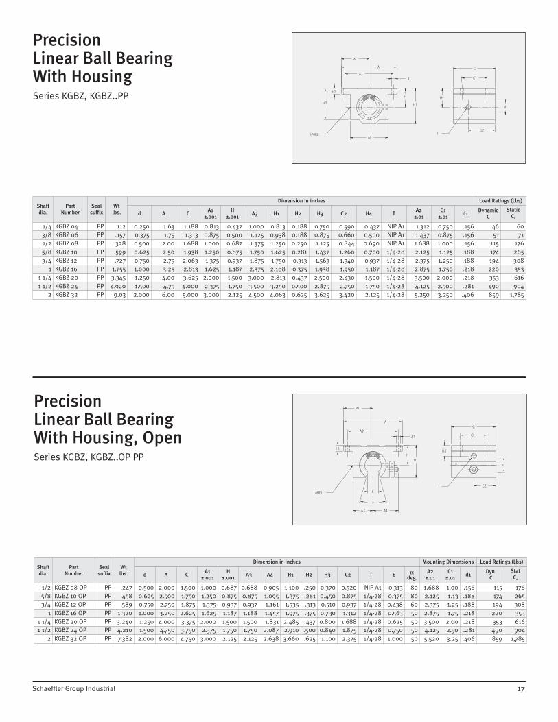
Self-AligningTandem Linear Ball BearingWith Housing, OpenSeries KTNZ..OP, KTNZ..OP PP
20
Self-AligningTandem Linear Ball BearingWith HousingSeries KTNZ, KTNZ..PP
ShaftDia.
PartNumber
Sealsuffix
Wt.lbs.
Dimensions in inches Basic Load Ratings
d A CA1
±.001H
±.001A3 H1 H2 H3 C2 H4 T
A2±.01
C1±.01
d1Dynamic
CStatic
C0
1/4 KTNZ 04 PP 0.21 0.250 1.63 2.50 0.813 0.437 1.000 0.813 0.188 0.750 1.250 0.437 NIP A1 1.312 2.000 .156 63 543/8 KTNZ 06 PP 0.27 0.375 1.75 2.75 0.875 0.500 1.125 0.938 0.188 0.875 1.375 0.500 NIP A1 1.437 2.250 .156 96 861/2 KTNZ 08 PP 0.51 0.500 2.00 3.50 1.000 0.687 1.375 1.250 0.250 1.125 1.750 0.687 NIP A1 1.688 2.500 .156 247 2245/8 KTNZ 10 PP 0.97 0.625 2.50 4.00 1.250 0.875 1.750 1.625 0.281 1.437 2.000 0.875 1/4-28 2.125 3.000 .188 281 3743/4 KTNZ 12 PP 1.25 0.750 2.75 4.50 1.375 0.937 1.875 1.750 0.313 1.563 2.250 0.937 1/4-28 2.375 3.500 .188 622 548
1 KTNZ 16 PP 2.58 1.000 3.25 6.00 1.625 1.187 2.375 2.188 0.375 1.938 3.000 1.187 1/4-28 2.875 4.500 .218 1,111 9841 1/4 KTNZ 20 PP 4.94 1.250 4.00 7.50 2.000 1.500 3.000 2.813 0.437 2.500 3.750 1.500 1/4-28 3.500 5.500 .218 1,652 1,4241 1/2 KTNZ 24 PP 7.73 1.500 4.75 9.00 2.375 1.750 3.500 3.250 0.500 2.875 4.500 1.750 1/4-28 4.125 6.500 .281 2,109 1,704
Shaftdia.
PartNumber
Sealsuffix
Wtlbs.
Dimension in inches Mounting Dimensions Load Ratings (Lbs)
d A CA1
±.001H
±.001A3 A4 H1 H2 H3 C2 T E
deg.A2
±.01C1
±.01d1 Dynamic C
StaticC0
1/2 KTNZ 08 OP PP 0.49 0.500 2.000 3.50 1.000 0.687 0.688 0.905 1.100 .250 .370 1.75 NIP A1 0.313 30 1.688 2.50 .156 247 2245/8 KTNZ 10 OP PP 0.90 0.625 2.500 4.00 1.250 0.875 0.875 1.095 1.375 .281 .450 2.00 1/4-28 0.375 30 2.125 3.00 .188 315 4583/4 KTNZ 12 OP PP 1.15 0.750 2.750 4.50 1.375 0.937 0.937 1.161 1.535 .313 .510 2.25 1/4-28 0.438 30 2.375 3.50 .188 386 558
1 KTNZ 16 OP PP 2.38 1.000 3.250 6.00 1.625 1.187 1.188 1.457 1.975 .375 .730 3.00 1/4-28 0.563 30 2.875 4.50 .218 690 1,0021 1/4 KTNZ 20 OP PP 4.61 1.250 4.000 7.50 2.000 1.500 1.500 1.831 2.485 .437 .800 3.75 1/4-28 0.625 30 3.500 5.50 .218 1,025 1,4521 1/2 KTNZ 24 OP PP 7.28 1.500 4.750 9.00 2.375 1.750 1.750 2.087 2.910 .500 .800 4.50 1/4-28 0.750 30 4.125 6.50 .281 1,307 1,734
Schaeffler Group Industrial

21
Precision Hardened& Ground ShaftingSeries WZ - Class L,SSeries WZ..PDT - Predrilled & Tapped, Class L,S
Series WZ..L, WZ..PDT
Shaftdia.nom
PPaarrtt NNuummbbeerr ToleranceRoundness
t1
Taper
t21)
Hardnessdepth
min
Surfacefinishing
maxStandard“L” class
Standard“S” class
Stainless SteelStandardTolerance“L” class
StandardTolerance “S” class
1/4 WZ 1/4" L WZ 1/4" S WZ 1/4" L-X90CRMOV18 —.0005/—.0010 —.0010/—.0015 0.0002 0.0002 0.016 RMS 123/8 WZ 3/8" L WZ 3/8" S WZ 3/8" L-X46CR13 —.0005/—.0010 —.0010/—.0015 0.0002 0.0002 0.016 RMS 121/2 WZ 1/2" L WZ 1/2" S WZ 1/2" L-X46CR13 —.0005/—.0010 —.0010/—.0015 0.0002 0.0002 0.024 RMS 125/8 WZ 5/8" L WZ 5/8" S WZ 5/8" L-X46CR13 —.0005/—.0010 —.0010/—.0015 0.0002 0.0003 0.024 RMS 123/4 WZ 3/4" L WZ 3/4" S WZ 3/4" L-X46CR13 —.0005/—.0010 —.0010/—.0015 0.0002 0.0003 0.035 RMS 12
1 WZ 1" L WZ 1" S WZ 1" L-X46CR13 —.0005/—.0010 —.0010/—.0015 0.0002 0.0003 0.035 RMS 121 1/8 WZ 1-1/8" L WZ 1-1/8" S WZ 1-1/8" L-X46CR13 —.0005/—.0010 — 0.0002 0.0003 0.059 RMS 121 1/4 WZ 1-1/4" L WZ 1-1/4" S WZ 1-1/4" L-X46CR13 —.0005/—.0010 —.0010/—.0015 0.0002 0.0004 0.059 RMS 121 1/2 WZ 1-1/2" L WZ 1-1/2" S WZ 1-1/2" L-X46CR13 —.0006/—.0011 —.0011/—.0016 0.0002 0.0004 0.059 RMS 12
2 WZ 2" L WZ 2" S WZ 2" L-X46CR13 —.0006/—.0013 —.0013/—.0020 0.0003 0.0005 0.059 RMS 12
Shaftdia.nom
INA Part NumberHole
SpacingX
ThreadSize
dStandard“L” class
Stainless Steel
1/2 WZ 1/2" L-PDT WZ 1/2" L-X46CR13-PDT 4 6-325/8 WZ 5/8" L-PDT WZ 5/8" L-X46CR13-PDT 4 8-323/4 WZ 3/4" L-PDT WZ 3/4" L-X46CR13-PDT 6 10-32
1 WZ 1" L-PDT WZ 1" L-X46CR13-PDT 6 1/4-201 1/4 WZ 1-1/4" L-PDT — 6 5/16-181 1/2 WZ 1-1/2" L-PDT WZ 1-1/2" L-X46CR13-PDT 8 3/8-16
2 WZ 2" L-PDT — 8 1/2-13
1) Measurement of diameter difference
Ordering Examples:Cut to length only: 3 pcs., 1 inch Class (L,S) x 39 inchesMachined to drawing: 3 pcs., 1 inch x 45 inches per drawing#...(attach drawing)
Dimension Table Series WZ • Dimension in inches
Dimension Table Series WZ..PDT • Dimension in inches
Ordering Examples:PDT shafting: 1 x PDT x 36 inches
y = 4 inchesPlease specify distance to
first hole, “Y” dimension, with order.
Special tolerances may be available, please contact your INA Sales Representative
Schaeffler Group Industrial

Shaft Support Rails& Assemblies DrilledTo Standard DimensionsSeries TSWZ..PD / TSWWZ
22
Shaft Support RailsSeries TSWZ
Shaftdia.
Part NumberWt.
lbs/ft
Dimension in inches
AH2)
±.002H1 A1
2)
1/2 TSWZ 08 0.60 1.50 1.125 .188 0.7505/8 TSWZ 10 0.78 1.63 1.125 .250 0.8133/4 TSWZ 12 1.01 1.75 1.500 .250 0.875
1 TSWZ 16 1.37 2.13 1.750 .250 1.0631 1/4 TSWZ 20 1.98 2.50 2.125 .313 1.2501 1/2 TSWZ 24 3.03 3.00 2.500 .375 1.500
2 TSWZ 32 4.80 3.75 3.250 .500 1.875
Shaftdia.
Part NumberRail only
Part NumberShaft & Rail Assembly
Wtlbs/ft
Dimension in inches Mounting Dimensions
A H3)
±.002H1 A2 A3 A1 d3 t d1 d2 A4 G
1/2 TSWZ 08 PD TSWWZ 08 0.60 1.50 1.125 .188 .208 .250 0.750 .281 .134 .169 .169 1.000 45/8 TSWZ 10 PD TSWWZ 10 0.78 1.63 1.125 .250 .251 .313 0.813 .312 .159 .193 .193 1.125 43/4 TSWZ 12 PD TSWWZ 12 1.01 1.75 1.500 .250 .294 .375 0.875 .375 .185 .221 .221 1.250 6
1 TSWZ 16 PD TSWWZ 16 1.37 2.13 1.750 .250 .379 .500 1.063 .437 .244 .281 .281 1.500 61 1/4 TSWZ 20 PD TSWWZ 20 1.98 2.50 2.125 .313 .465 .563 1.250 .531 .306 .343 .343 1.875 61 1/2 TSWZ 24 PD TSWWZ 24 3.03 3.00 2.500 .375 .550 .688 1.500 .625 .368 .406 .343 2.250 8
2 TSWZ 32 PD TSWWZ 32 4.8 3.75 3.250 .500 .721 .875 1.875 .812 .492 .531 .406 2.750 8
1) Maximum length L = 482) With reference to the nominal shaft diameter, measured while clamped
1) Maximum length L = 482) The dimension C is dependent on the length of the support rail. It should always be equal at both ends3) With reference to the nominal shaft diameter, measured while clamped
Schaeffler Group Industrial

23
Shaft Support RailsLow ProfileSeries TSUZ
Shaftdia.
INA Part Number Wt
lbs/ft
Dimension in inches
d AH2)
±.002H1 A1
2) A2
1/2 TSUZ 08 .11 0.50 0.37 0.562 .120 .185 .2165/8 TSUZ 10 .17 0.63 0.45 0.687 .120 .225 .2693/4 TSUZ 12 .20 0.75 0.51 0.750 .120 .225 .317
1 TSUZ 16 .35 1.00 0.69 1.000 .120 .345 .4221 1/4 TSUZ 20 .44 1.25 0.78 1.187 .200 .390 .5231 1/2 TSUZ 24 .58 1.50 0.93 1.375 .200 .465 .625
2 TSUZ 32 .89 2.00 1.18 1.750 .250 .590 .824
1) Maximum length L = 482) With reference to the nominal shaft diameter, measured while clamped
Shaft Support RailsLow ProfileDrilled To Standard DimensionsSeries TSUZ..PD
Shaftdia.
INA Part Number Wt
lbs/ft
Dimension in inches Mounting Dimensions
Gd A H 3) H1
±.002A13) A2 d2
1/2 TSUZ 08 PD 0.11 0.50 0.37 .562 .120 .185 .216 .169 45/8 TSUZ 10 PD 0.17 0.63 0.45 .687 .120 .225 .269 .193 43/4 TSUZ 12 PD 0.20 0.75 0.51 .750 .120 .255 .317 .221 6
1 TSUZ 16 PD 0.35 1.00 0.69 1.000 .120 .345 .422 .281 61 1/4 TSUZ 20 PD 0.44 1.25 0.78 1.187 .200 .390 .523 .343 61 1/2 TSUZ 24 PD 0.58 1.50 0.93 1.375 .200 .465 .623 .406 8
2 TSUZ 32 PD 0.89 2.00 1.18 1.750 .250 .590 .824 .531 8
1) Maximum length L = 482) The dimension C is dependent on the length of the support rail. It should always be equal at both ends3) With reference to the nominal shaft diameter, measured while clamped
Schaeffler Group Industrial

Shaft EndSupport BlocksSeries GWZ
Series GWZ
24
Shaftdia. Part Number
Wtoz.
Dimension in inches Mounting Dimensions
H±.002 A B C D H1 A1 d2 Bolt
1/4 GWZ 04 0.53 .6875 1.500 1.063 .500 .500 .250 1.125 .156 #63/8 GWZ 06 0.74 .7500 1.625 1.187 .688 .563 .250 1.250 .156 #61/2 GWZ 08 1.24 1.000 2.000 1.625 .875 .625 .250 1.500 .188 #85/8 GWZ 10 1.84 1.000 2.500 1.750 1.00 .688 .313 1.875 .218 #103/4 GWZ 12 2.61 1.250 2.500 2.063 1.25 .750 .313 2.000 .218 #10
1 GWZ 16 4.80 1.500 3.063 2.500 1.50 1.00 .375 2.500 .281 1/41 1/4 GWZ 20 8.97 1.750 3.750 3.000 2.00 1.13 .438 3.000 .346 5/161 1/2 GWZ 24 12.00 2.000 4.375 3.437 2.25 1.25 .500 3.500 .346 5/16
2 GWZ 32 23.65 2.500 5.500 4.375 3.00 1.50 .625 4.500 .406 3/8
Schaeffler Group Industrial
Corporate Offices
Schaeffler Group USA Inc.308 Springhill Farm Road
Fort Mill, South Carolina 29715Telephone: 803-548-8500
Fax: 803-548-8599USA SALES OFFICES
ATLANTA207 N. Lewis Avenue, Suite GLaGrange, GA 30240Telephone: 706-883-7305Fax: 706-883-7315
CHARLOTTE377 Carowinds Boulevard, Suite 120Fort Mill, South Carolina 29708Telephone: 803-547-7970Fax: 803-548-6361
CHICAGO2525 Cabot Drive, Suite 110Lisle, Illinois 60532Telephone: 630-955-9360Fax: 630-955-9365
CLEVELAND12306 Woodward BoulevardGarfield Heights, Ohio 44125Telephone: 216-587-4393Fax: 216-587-2655
DALLAS1660 South Stemmons Fwy., Suite 360Lewisville, Texas 75067Telephone: 972-221-5150Fax: 972-221-5373
DAYTON261 Regency Ridge DriveCenterville, Ohio 45459Telephone: 937-433-6404Fax: 937-433-6814
DETROIT1750 East Big Beaver RoadTroy, Michigan 48083Telephone: 248-528-9080Fax: 248-528-4381
HOUSTON10101 Southwest Freeway, Suite 400Houston, Texas 77074Telephone: 713-219-1430Fax: 713-219-1431
KANSAS CITY14425 College Blvd., Suite 110Lenexa, Kansas 66215Telephone: 913-451-0300Fax: 913-451-0302
LOS ANGELES34700 Pacific Coast Highway, Suite 203Capistrano Beach, CA 92624Tel: 949-234-9799Fax: 949-234-9899
LOUISVILLE14419 Micawber WayLouisville, Kentucky 40245Telephone: 502-254-9590Fax: 502-254-2760
MEMPHIS1922 Exeter Road, Suite 20Germantown, Tennessee 38138Telephone: 901-756-0023Fax: 901-756-0260
MILWAUKEEN16 W23233 Stoneridge Drive, Suite 170Waukesha, Wisconsin 53188Telephone: 262-544-8270Fax: 262-544-8271
MINNEAPOLIS80 W. 78th Street, Suite 270CChanhassen, Minnesota 55317Telephone: 952-934-8822Fax: 952-934-8833
PHILADELPHIA3000 Cabot Blvd. West, Suite 220Langhorne, PA 19047Telephone: 215-891-8500Fax: 215-891-0554
PHOENIX6619 N. Scottsdale Road, Suite 5Scottsdale, Arizona 85250Telephone: 480-296-2060Fax: 480-596-5745
QUAD CITIES300 NW Banktower, 2550 Middle RoadBettendorf, Iowa 52722Telephone: 563-355-0383Fax: 319-355-1937
SEATTLE40 Lake Bellevue, Suite 100Bellevue, Washington 98005Telephone: 425-646-9477Fax: 425-646-9471

KXKB
ZU
S0
6070
3
ALL RIGHTS RESERVED
Schaeffler Group USA Inc.308 Springhill Farm RoadFort Mill, South Carolina
Reproduction of this publication in whole or inpart without the express written consent ofSchaeffler Group USA, Inc. is prohibited.
Although every effort has been made to ensurethe accuracy of the information contained in thiscatalog, Schaeffler Group USA, Inc. shall not beliable for any omissions or errors.Purchasers should conduct their own testing todetermine the suitability of any product for a particular purpose. In no event shall SchaefflerGroup USA, Inc. be liable for any claims for damages based upon breach of warranty, breachof contract, negligence, strict liability in tort, orany other legal theory.
All sales from catalog orders are subject to theStandard Terms and Conditions of Sale. Pleasecontact your Schaeffler Group USA SalesRepresentative for a copy of the Standard Termsand Conditions of Sale.
Printed in the United States.
©Copyright 2006
Schaeffler Group USA, Inc.308 Springhill Farm RoadFort Mill, South Carolina 29715 Phone: (803)548-8500Fax: (803)548-8599www.ina.com/us