Embed Size (px)
Citation preview
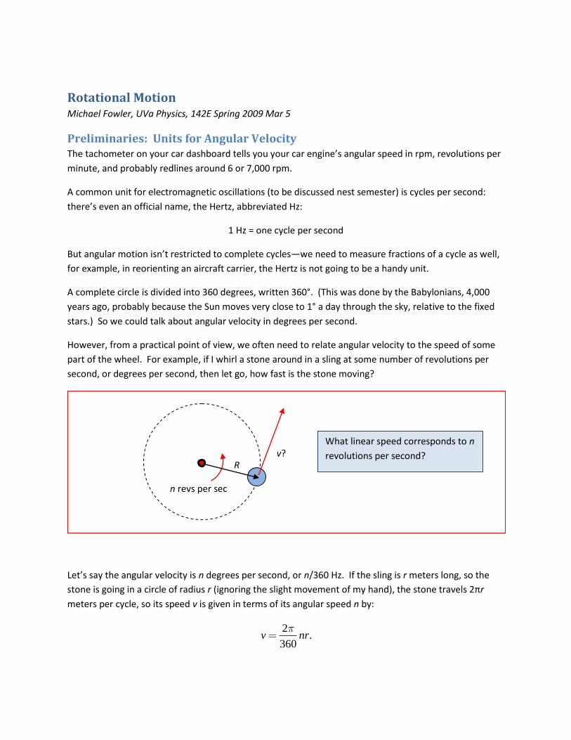
Rotational Motion Michael Fowler, UVa Physics, 142E Spring 2009 Mar 5
Preliminaries: Units for Angular Velocity The tachometer on your car dashboard tells you your car engine’s angular speed in rpm, revolutions per
minute, and probably redlines around 6 or 7,000 rpm.
A common unit for electromagnetic oscillations (to be discussed nest semester) is cycles per second:
there’s even an official name, the Hertz, abbreviated Hz:
1 Hz = one cycle per second
But angular motion isn’t restricted to complete cycles—we need to measure fractions of a cycle as well,
for example, in reorienting an aircraft carrier, the Hertz is not going to be a handy unit.
A complete circle is divided into 360 degrees, written 360°. (This was done by the Babylonians, 4,000
years ago, probably because the Sun moves very close to 1° a day through the sky, relative to the fixed
stars.) So we could talk about angular velocity in degrees per second.
However, from a practical point of view, we often need to relate angular velocity to the speed of some
part of the wheel. For example, if I whirl a stone around in a sling at some number of revolutions per
second, or degrees per second, then let go, how fast is the stone moving?
Let’s say the angular velocity is n degrees per second, or n/360 Hz. If the sling is r meters long, so the
stone is going in a circle of radius r (ignoring the slight movement of my hand), the stone travels 2πr
meters per cycle, so its speed v is given in terms of its angular speed n by:
2
.360
v nr
R
n revs per sec
v? What linear speed corresponds to n
revolutions per second?

2
This rather clumsy formula is a consequence of following the Babylonians in defining the unit of angle as
1/360 of a full circle. We’d have a much nicer formula if instead we defined our unit of angle as 1/2π of
a full circle!
So we define: the radian = 1/2π of a full circle. This works out to be about 57.3°, and since the
complete circumference of a circle is 2πr, the distance around the circle corresponding to an angle of
one radian is one radius. Duh.
It’s easy to see that radians are the natural angle unit for trig: look at the sine of a small angle.
Our default notation for an angle is θ, measured from the x-axis, with counterclockwise as positive.
Angular velocity in radians per second will usually be denoted by ω: / .d dt
So if a wheel is rotating at positive angular velocity ω radians per second about a fixed axle, a point on
the wheel at distance r from the axle is moving at speed
v r
a formula we’ll be using a lot.
The standard notation for angular acceleration is 2 2/ / .d dt d dt
Notice that if we have constant angular acceleration, formulas for angular velocity and angular
displacement (meaning angle turned through) are just like those for linear motion under constant force:
Angle of one radian
the red solid arc has length
equal to the radius of the circle.
sinθ ≈ θ for θ small
for r = 1, the arc length is θ,
the short black line = sinθ.

3
0
210 0 2
2 2
0 02 ( ).
t
t t
Just be sure your system has constant angular acceleration before using these formulas!
Torque: Seesaw Physics Torque is a measure of the effectiveness of a force in getting something rotating: actually we’ve come
across this already in the discussion of the seesaw. If a child sits at the end of a level empty seesaw, it
begins to rotate. O.K., it doesn’t get far, but there is angular acceleration. And we know the if the child
sits close to the pivot point, the seesaw turns more slowly.
We’ve also seen that two children, one twice as heavy sitting at half the distance, balance—we said they
had the same leverage. This “leverage” is actually what’s called torque. It’s also called the “moment” of
a force about an axis of rotation. It’s the product of the weight of the child and the distance from the
pivot or axle.
So, for a 20 kg child at a distance of 1.5m, the torque about the pivot point is 300 N.m, setting g = 10.
We can also have two forces on the same side of the pivot balancing—if one of them is upwards. If a
20kg child is sitting half way to the pivot, with no-one on the other side, you could lift the seesaw to a
horizontal position by supplying an upward force equivalent to 10 kg weight at the end of the seesaw,
the same side as the child.
d 2d
2mg mg
Balancing a seesaw

4
One further point: what if you supplied the upward force by tying a (light) rope to the end of the
seesaw, and tugging at some angle? In that case, the tension in the rope, where it pulls on the seesaw,
is equivalent to a force perpendicular to the seesaw plus a force parallel. The latter component does
nothing (unless the seesaw can move sideways), the upward component is all that counts.
There’s another way to look at this which is sometimes useful: instead of resolving the force into
components at its point of application, as in the diagram above, we can take the whole force, acting
along the line in space through its point of application, but calculate its leverage—the torque—by taking
the lever arm to be the distance from the pivot point to the line of the force:
d
2d
2mg
T = 2mg
Only the upward rope force component counts
angle 30°
2mg mg
√3mg
d
2d
2mg
T = mg
Balancing a seesaw the hard way

5
Either way, the formula for torque strength is:
sinFr
where F is the magnitude of the force, r the distance from the pivot of the point of application, and θ
the angle between the vector r
from the pivot point to where the force acts and the force F
.
Rotational Equivalent of Newton’s First Law By the time Galileo noticed that a smooth ball on a flat surface with little friction would keep the same
velocity a long time, it was already known that a rotating grindstone, with a well-oiled axle, would keep
spinning a long time too—and this, taken to the ideal limit, is Newton’s First Law for rotation: in the
absence of torque, a body will spin at constant angular velocity indefinitely.
It’s worth mentioning that a vertical grindstone must have the axle through the center of gravity. If this
is not the case, gravity will exert a torque, and although the wheel might keep spinning, it won’t be at
constant angular velocity.
In fact, the torque on such an off-center wheel is given by CM CMsinMgr Mgx , where rCM is the
distance of the center of mass from the axle, and θ the angle between CMr
and the vertical.
To prove this, imagine the wheel to be made up of a large number of glued-together small masses mi at
positions ir
.
2d T = 2mg
Torque = force × distance of line of force from pivot = 4mgdsin30 = 2mgd
angle 30°
2dsin30

6
As discussed in the preceding section, the torque about the axle of the weight of the small mass mi is
equal to mig multiplied by the perpendicular distance from the axle to the line of action of the force,
that is, migxi , taking the axle as the origin of coordinates.
Evidently the magnitude of the total gravitational torque from the imbalance
CMi i
i
m gx Mgx
from the definition of the center of mass.
Kinds of Equilibrium If there is no friction at the axle, the wheel can only be at rest if the center of mass lies on the vertical
line through the axle. If the center of mass is directly above the axle, the wheel might be at rest, but the
slightest push will start it turning: this is called “unstable equilibrium”. If the center of mass is below the
axle, a slight push to one side will cause the wheel to swing back then oscillate, a topic we’ll return to
later—this is “stable equilibrium”. If the center of mass is exactly at the axle, the wheel will rotate at a
steady rate—this is “neutral equilibrium”. These all have analogies in linear motion: assuming no
friction, unstable equilibrium is a ball perched on a mountaintop, stable is a ball sitting at the bottom of
a valley, and neutral is a ball on a flat plane. In two dimensions, there are more complicated
possibilities: a ball in the middle of a saddle might be stable for displacements parallel to the horse, but
unstable for displacement the other way. Situations analogous to this horsy example do in fact occur in
physical systems.
Rotational Equivalent of Newton’s Second Law
A Simple Example: Introducing the Moment of Inertia
Newton’s Second Law, in the form F ma
, states that an object undergoes linear acceleration in
response to an net external force, and the mass determines the magnitude of this response. It’s pretty
mig
mi
xi
axle Torque around axle
from small part of
an off-center wheel
τi = migxi.

7
clear by now that the angular version must be that an object undergoes angular acceleration in response
to an net external torque—but it’s less clear what plays the role of mass this time.
To find out, we’ll look at an example of angular acceleration which is almost the same as linear
acceleration.
Suppose a mass M is firmly attached to a horizontal disk of negligible mass on a frictionless vertical axle,
so that the mass M must go around in a horizontal circle. Assume the mass is initially at rest, then the
force F is applied. What happens in the first few moments?
Well, of course, the mass accelerates with acceleration a = F/M. As soon as it reaches a significant
speed, the disk will begin to exert a force towards the center, to keep it on its circular path, but let’s just
concentrate on those first few moments before that effect becomes important.
Let’s translate that initial acceleration into angular language. Since the angular velocity is related to
the actual velocity by v = R , the angular acceleration must be related to the ordinary acceleration a
along a tangential direction by a = R . So we can see how to connect the two accelerations.
Now we must connect the two forces, or, rather, the linear force F with the torque acting on the
system mass + wheel.
The torque is just equal to the force F multiplied by its leverage arm R, that is, = FR. Putting this
together with a = R , we find that F = Ma translates to:
= FR = MaR = MR2
Comparing this equation, = MR2 , with F = Ma, we notice that the quantity MR2 plays the role of
mass, or inertia, in rotational dynamics for this simple case. It is called the moment of inertia, and
labeled I. We show in the next section that for more complicated rigid bodies, = I is still correct, and
I is a sum over the body of terms like MR2.
M
R
ω = dθ/dt F
The mass M has speed v = Rω
and acceleration a = Rdω/dt = Rα axle

8
Moments of Inertia for Extended Bodies
We’ve only found the “moment of inertia” for a single mass attached to a light disk. What about
something more complicated, for example a heavy disk?
The key to finding the moment of inertia for a solid body is to visualize it as a lot of small masses all
glued together. Think specifically of a heavy wheel of radius R, rotating about a fixed axle with negligible
friction. Imagine the wheel to be initially at rest, then a force F is applied to the rim tangentially, so that
the torque is FR. Of course, the whole wheel begins to rotate, so think what happens to one of the small
masses mi we are imagining the wheel to be made up of. If it is at a distance ri from the axle, and the
initial angular acceleration of the wheel is , this small mass, mi say, must experience an initial
acceleration ri , so there must be a total force on it of fi = miri , and therefore a torque acting on it of
firi = miri2 .
But where, exactly does this torque come from? Ultimately, it must come from the force F being
applied to a different part of the wheel, but the immediate cause for the small mass mi’s acceleration is
just the pulls and pushes of its neighbors.
In other words, if you push on one part of the wheel, since it’s a solid body its rigidity transmits the
effect of the force to all the other parts, so the wheel rotates as a whole—provided of course the force
is not strong enough to tear the wheel apart.
Since the torque felt by one small part of the wheel τi = miri2 , the total torque felt by all the parts of
the wheel is:
τ = Στi = miri2 = dmr2
with the integral being over all the tiny masses dm making up the wheel.
Rigid wheel made up of
many little masses mi :
when external torque
FR is applied, mi has
initial linear
acceleration riα, so
experiences torque:
τi = firi = miri2
F ri
axle
mi

9
Now comes a crucial point. How do we relate this torque to the external force torque FR? What about
all the internal forces—the fact that each part of the wheel feels forces from neighboring parts? How do
we take account of this very complicated situation?
The answer is: we don’t have to! By Newton’s Third Law, all those internal forces are in equal opposite
pairs, actions and reactions between neighboring masses. This means that when we sum over all parts
of the wheel, we count all these forces, and they all cancel each other in pairs.
Therefore the total torque is just that from the external forces.
It follows that the analog of Newton’s Second Law for rotation about an axle is
Torque = I
where the moment of inertia I is given by miri2 = dmr2 . (And remember that as always the
acceleration must be measures in radians/sec2.)
Moments of Inertia: Hoops, Disks, Cylinders, Rods.
Finding the moment of inertia l is now just a matter of doing elementary integrals. For the case of a
hoop of mass M, where all the mass can be taken at the same distance R from the axis of rotation, no
integral at all is necessary:
For a hoop, I = MR2.
A disk can be thought of as constructed of successive hoops, like a two-dimensional onion. As a
practical matter, the best approach is to use the two-dimensional density, call it , (units: kg/m2) so
that the total mass of the disk is density x total area, M = R2. Then the “hoop” which is that part of
the disk between r and r + Δr from the center has mass m = 2rΔr , and that hoop has moment of
inertia mr2 = (2rΔrr2.
A disk can be seen as
made of concentric
hoops glued together. axle
r
r + Δr R

10
Then just do an integral to add up the moments of inertia of all the nested hoops from 0 to R to find the
moment of inertia of the disk:
3 4 21 1disk 2 2
0
2 .
R
I r dr R MR
The same expression works for a cylinder, which for these purposes is just a stack of disks.
What about a rod about one end? Assume its (constant) linear density is λ kg/m., so a length dx has
mass λdx. Then the moment of inertia is
2 3 2
0
/ 3 / 3.
L
I x dx L ML
Suppose such a rod is hinged at one end, horizontal, and falls. What is the initial acceleration of its end?
2/ 2 ( / 3)
3 / 2.
MgL I ML
gL
So the end accelerates at Lα = 3g/2.
If it is at first sight surprising that the end of the rod accelerates downwards faster then g, consider the
following system: a very light rod, hinged at one end, with a large weight attached to its middle.
A very light rod hinged to a wall at one end has a mass at
its center: how fast will the rod’s free end accelerate
downwards on release from a horizontal position?

11
If let go from a horizontal position, the weight will completely dominate the situation, and accelerated
downwards very close to g. This means the far end of the light rod is forced downwards at close to 2g.
Our example above is not that extreme, but the same idea.
The Parallel Axis Theorem
If we know the moment of inertia of an object about a line through the center of mass, the moment of
inertia about any parallel line is easily found.
We’ll prove this for a two-dimensional object (really a thin three-dimensional object):
With the notation in the diagram, 2
CM i i
i
I m r , and recall 0.i i
i
m r
Now
2 2
newaxis
2
CM
2
CM
( )
2
.
i i i i
i i
i i i
i i
I m r m r h
I h m r m h
I Mh
This is the Parallel Axis Theorem:
2
newaxis CM .I I Mh
where h is the perpendicular distance between the new axis and the parallel axis through the center of
gravity. It’s easy to extend this proof to a three-dimensional object: taking the parallel axes to be in the
z-direction, replace ir
with (xi, yi).
ir
h
new axis
center of mass
mi ir
The moment of inertia of the two-dimensional object about any axis
perpendicular to the object is simply related to that about the
parallel axis through the center of mass.

12
Varying Moment of Inertia Newton did not actually write his Second Law as F = ma = mdv/dt, but as F = dp/dt, where p = mv is
called the momentum, and in fact this is the correct description of nature in cases where the mass of an
object varies, such as a rocket expelling fuel, or a falling raindrop growing from condensation.
Similarly, the rotational Second Law = Icould be written more generally as
dI
dt
to allow for the possibility of a varying moment of inertia, and this is much more common than a varying
mass. Think of a spinning dancer or skater throwing her arms out and bringing them in, or of a diver
curling up and uncurling his rotating body. The external torques are pretty small under these conditions,
the variation in spin speed is largely due to the changing moment of inertia and the constancy of the
total angular momentum IThe observed variations in angular velocity confirm the validity of the more
general law.
Rotational Kinetic Energy A rotating object has kinetic energy even if its center of mass is at rest. Think of it as composed of many
small masses mi at distances ri from the center of mass.
Then if the angular velocity is mi has speed vi = ri, and kinetic energy ½ miri22, and summing these,
KE of rotation = ½ I2.
If a net torque is acting, this energy will change:
212
d dI I I
dt dt
so the rate of working, the power, of a torque equals the magnitude of the torque multiplied by the
angular velocity, just as a force F moving something at speed v is working at a rate Fv.
This equation can also be integrated:
212
dd I dt dt d
dt
The total change in kinetic energy equals the integral of torque times angular distance, valid even if the
torque is varying.
Rolling Down a Ramp For example, we’ll take the case of a hoop of radius R rolling down a ramp without slipping. Suppose at
some instant the center of the hoop is moving with speed v. Of course, other points on the hoop are

13
moving at different speeds. The point at the bottom in contact with the ramp isn’t moving at all at that
instant. But in the frame of reference in which the center of mass is momentarily stationary, that point
is moving backwards at R. This means that the angular speed and the linear speed of the center of
mass are related by v = R.
What is the total energy of the rolling hoop? Imagine as usual that it is made up of a large number of
small masses mi. If the small mass mi has velocity vi, the total energy is ½ mvi2. Since its both moving
along and rolling, let’s write the velocity of the small mass mi as
CMi iv v u
where iu
is the velocity of the small mass mi relative to the center of mass.
Then the total kinetic energy of all the small masses
22 2 21 1 1 1CM2 2 2 2
.i i i i CM CM i i i i
i i i i
mv m v u Mv v mu mu
The first term is just the ordinary kinetic energy of linear motion, the last term is the same as the kinetic
energy of rotation for the center of mass at rest. The middle term is zero, because the sum is just the
linear momentum in the center of mass frame, which is zero. ( 0i i i i
i i
dmu m r
dt
in the frame
in which the center of mass is at rest.)
0
v = Rω
Velocities of parts of hoop relative to
its center: v = Rω perpendicular to
the radius.
Velocities relative to the ramp for no-
slip: zero at point of contact, v at
center of hoop, 2v at farthest point.
v
2v
ω

14
Therefore, the total energy is just the sum of the translational kinetic energy and the rotational kinetic
energy:
2 21 12 2CME Mv I
where I is the moment of inertia about the center of mass.
So what does this mean for the hoop? If it’s rolling at speed v, it’s rotating at angular speed v/R ,
and since its moment of inertia is MR2, its total energy is
2 2 2 2 2 21 1 1 12 2 2 2
( / ) .E Mv I Mv MR v R Mv
So it has twice the kinetic energy of a block of the same mass sliding down at the same speed. Put
another way, a block sliding down through a height h will have speed given by v2 = 2gh, the hoop will
only reach speed v2 = gh, because it will have lost the same amount of potential energy, so must have
the same total kinetic energy—including the rotational kinetic energy, which the block didn’t have.
The equation F = ma still describes its linear motion down the ramp, and after descending a distance x
its velocity is given by v2 = 2ax. Evidently, the rolling hoop has only half the acceleration of the sliding
block, so must only be subject to half the force pulling it downhill. The difference is the retarding static
frictional force at the point of contact: that must be just half of the gravitational force component
pointing down the hill. If there isn’t enough friction, the hoop will slide without increasing its angular
velocity. (Note: the hoop has only half the acceleration of the block, but reaches a final velocity greater
than half that of the block, because it accelerates for a longer time.)