Embed Size (px)
Citation preview

'1
I
I
JOURNAL OF RESEARCH of the National Bureau of Standards- C. Engineering a nd Instrumentation Vol. 66C, No. 4, October- December 1962
Rotational Micromanometers
Karl Lofquist
(Jun e 7, HJ6:2)
A rotational manometer may be defin ed as an instrument which measures a p ress ure d ifference b.v balancing against it a known press ure difference generated by a ro t ating elemen t . A s ingle fluid is used, a nd ba lance is det ermined by the absence of flow in a detector. In one ty pe, the centrifuga l manom e te r, the rot or-generated press ure is independent of molecula r viscosity and is predict a ble. This instrume nt , which has been previously invest igated a nd tes ted in a ir, is here adapted for usc in water. Under the conditions of test, it p roved repeat ab le t o wi t hin a bou t ± 2 percent , for pressure differences above 1 dyne cm- 2, a nd t o about ± 10 percent for pressure differe nces down to 1(10 d yne cm- 2 • An alternate ty pe, in whi ch t he ro tor-ge nerated pressures de pend upon viscosity , was found , whe n tested , to be unsatisfactory. A simple ge neral a na l.vsis, suppo rted by obse lT a t ions, shows t he depe nde nce of ma nometer sc nsit i,·iL.v upo n t he rpsistancp of t he s.I' ste m a nd t he des ign of t he fl o ll· detector."'
1. Introduction
Kel11p l JutS describcd II, lll icrOl1lanolllcter in which a known pressure d ifference is ge nerated by centrifugal accelemtions in a rotor Lo balan ce an unknown pressure difference. Balance is determined by the absen ce o[ flo \\- in a detector containing suspendcd particles. He Jl/1S constructed such an ins trulli ent, the "cent,ri fugal 111lwometer," for usc in air and has found it to perform very satis[actori ly.
A Ill ano illeter if this type hits several advantages for m easurClll e11t of a pressure difference b etween two points in a &iven fluid , providing onl~T thl1t the differen ce is nearly s teady. [t contains but a single fluid , the SILl ll e as tiln,t given. Consequently, with no fluid in conhwL with another , th er e is no Illeniscus or bubble and no coluilln or liquid to be measured . Any change in [.h e unknown pressure ciifferen(".c accelerates th e flo \\' in the detec tor almost iml1l ediately, <tnd (,!tere is no lag associated with the fillin g and emptyin g or reservoirs. This advantage is much greater for nl easurements in water than in ail', as such a lag in creases with the inertia and viscosity of the fluid . Sin ce the operation of the manOineter is independent of the action or gravity, it does not need to be level and does not require a steady platform. Tlw principle of operation is simple and, with careful design, the perfoJ' III Mlce can be predicted with nccuracy sufficient to make a calibration unnecess<try. Fi nally , since the k nowll pressure differen ce created within the instru ment does not require ther lll itl expansion or compressibility of the fluid, such H, mano meter is suitable [or use in a liquid .
T he primn lT effort descri bed here is the design and test of a ce ntrifugal manometer adapted for use in water. This adaptatio n involves, OIl the one hand, such practical problems as the choice of particles to be sLlspended nnd the control of bearing leakage, bubble formation , H.nd lempemture yaria-
1.T. F . K emp , Centr ifu gal IT'u ncmcler , .T. Basic E ng., PI'. 341 - 347 (Sept. 1959) .
Lioll S. On the other hand is tlte qu es tion of to whitt exten t the predictab il ity of perform ance, found by Kemp , wi ll be repeated in <l prcss ure gen era tor of qui te differen t size an d design , in particular, witll it rotor or much smaller diameter .
Secondly , as will be seen, the concept of th e C'c lltrirugld JllltilO lneter is easily generalized to tlltt t of the "rotational" manol1lete r, a clnss which includes I11Hn)" addit ional possible designs. Since these designs differ only ill their press ure ge nerators, retaining th e same sys tem or rotor drive and flow detection , it W<lS found con veni ent to te t one and compare its performan ce witb Lbnt of the centrilng'll mano me tel' .
Finally, th e sc nsitivi ty of mnnometers of a rotational type is in ves tigaled Lo determin e upon Wh ll t fadors i t depends nnd ho\\- i t can be in creased .
2. General Description
2 .1. Principle of Rota tiona l Manometers
The general principle of the rotational manometer is easily derived. It will be found most convenient to treat the centrifugal manometer and the alternative " viscous" manometer la ter as special cases .
If a solid of revolution is rotated abou t its axis in a cavity filled with a fluid, the preSSll1'e varies from point to point throughout the fluid. Points within the solid may be included if they are accessible through suitable passageways. It is assumed tha t the r a te of rotation is constant and that tbe pressure at all points is steady. D enoting the press ure difference between any two selected fixed points by !:lp , a characteristic length of the system. by L, the density and kin ematic viscosity of the (in compressible) fluid by p and II , and t he rate 0[" ro tation by fl , a simple dimen sional amtlysis shows tha t
D !:l~= f(Drl) p1l2 . II
(1)
363

-------------- -- ----
01' alternately,
~=F(DfI.). DpQ2 v
(2)
The function..1, or F, c.an be determined by expeJ'imen t and, 111 exceptIOnal cases, by theoretical analysis.
If now, in a separate fluid of the same properties a "pressure difference t:..p' exists between two givel~ po~nts (as say on a pitot-static tube) and these pom ts are connected by suitable conduits to the pr:evi~usly men tioned poin ts in the ca vi ty, a curren t wIll , 111 generftl, f10w through the conduits . But if the rate of rotation is adjusted such that t:..p equaJs t:..p' , the current will stop. Thus if j is known and t:..p' is unknown , the cavity and'r'otatin o
solid, with a motor and drive to rotate it and with a sensing element to detect conduit flow 'constitute a rotational manometer which determil;es t:..p' by ~q ( ~) whene-:er the f10w is stopped. Conversely, If t:..p can be gIven known values, tlle same apparatus can be used to determine.f.
3. Water Manometer System
The components and gencral scheme of the water ~'otational manometer are shown in the photograph In figure l. The motor and drive at the right turn the rotor within the cavity housing seen at the left center. The pressure generator shown is that of the centrifugal manometer. The flow detector is at the far left. In operation, the conduit at the left of the thI:ee .open nipples shown in front of the cavity-rotor umt IS connected to the external source of lower "pressure. It then passes through the detector and Into the r~to~' or cavity. The. circuit is completed by the condmt 111 the cent~r ~vhlCh connects the cavity to the external source of hIgher pressure.
It is necessary to prevent anv leak or bubble formation in the system as these ~ause spurious movement through the flow detector. The conduit at the right in figure 1, which is not part o[ the circuit, connects an external water source to a point near the outside end of the drive shaft bearing to make the pressure at this point nearly equal to that in the cavity. Any leak out of the bearing, when this
FIGURE 1. The water rotational manometer.
1?ressure is greater than atmospheric, is then drawn !rom the extcl'l1al source only. If the cavity prcssure IS less than atmospheric, the bearinO' conduit can be used to keep air from entering th~ system. This method of leak prevention , rather than the use of sO~l1e fonl~ of p3;cking: g~and, wfl:s .chosen to keep the dI'lv~ ~h~!t beaI'lng fnctIOn neglIgIble compared with the i~'IctIOn between the cones in the drive system descnbed below. To preveut bubble formation water y,sed to ~ll the system was previously degassed by ):>oIlIng. Smce the volume How during an observatIOn was extremely small, this water rem ained in the systcm practically indefinitely.
In any l~otatio~lal manomet.er it is llecessary that the rate of rotatIOn can b e given any value within the operating range and there be lleld constant. For these purposes, a synchronous motor was used with a dri."e '~hi~h included a system of gear sclections and a pall' o[ slIghtly tapered cones for continuous speed control. Torque was transmitted from one cone to the othcr by a weighted wheel 'with a narrow rubber (O-ring) perimeter. These components Cl1n be seen in figure 1.
In the calibratiOl:s, the period T = 27rjQ, rather than fl.,. was measured dn·ectly. This was dOll e by timing, With a stop ,v:atch, a convenient number of cycles of the rot?r shatt, the nl!mb~l~ chosen .so that the timing lasted for around 1 mIll. Ihe readIllgs were found to be repeatable to within about 0.3 sec, that is to about ~~ percent, except at the highest speeds ,.; hen some slIp between the cones became noticeable . In the calibrations, valucs or T ranged from 14.0 sec down to 0.35 sec.
The fiow detector was similar to that described in rootno~e [1], except that there the suspended particles were 011 droplets. A nanow shaft of lio'ht from a vertical filament passed through a glass-w:tled section of the conduit and illuminated sm all particles in the water. Light rays emanating from the particles were then deHected upward by a prislJl and observed
prism
))
,--- /y/ B //
)) //
light beam f/ A-A
B- B
to microscope
c-c
I
J
1
FIGURE 2. The design of the flow detector in the vicinity of the : suspended particles.
(The glass walls are IfIll-in. apart.)
364

l
k ,
through a low power (ilbout 70 X ) microscope. Th e an0 1e between the shaft of ligh t and the normill to th~ walls was sufficient. (about 45°) to provide a dilrk background for the illuminated particles. These were of fine clay which, it was found, usually contained miscellaneous organic material. The particles could b e replenished through a hole ill the Lop of Lhe section from a syringe serving as a r eservoir. The smaller particles, whether clay or organic (i t was seldom obvious), showed no tendency to settle and the r eservoir was neeCled only occasionally.
The desigl1 of the flow detector in the vicinity of the suspended particles is shown schem:=ttically in figure 2. The circle, drawn on the slde VIeW, shows the approximate field of vision., seeJ? thro,:!gl: tl~e microscope, and the two vertIcal hnes wlthm It represen t thin wires which were placed m the focal plane within the barrel of the microscope .
4. Calibration Systems
Known pressure differ en ces were provided by two calibration systems. The first consisted of t~vo bottles of known diameters and partly filled wlth water, with a syrin ge, connected to a mi~rometer which injected a known volume of water llltO one of the bot tles thereby increasing the depth o[ water by a known ~mount. The useful range in !:,.p' [or the bottles was roughly, between 100 dynes cm-2 and 1 dyne cm- 2• 'In a second system, the "Poiseuille apparatus," the pressure differe?ce b~tween two taps on the side of a long circular plpe, WIth carefully measured diameter, was calculated from the known rate of flow. This flow, from one vessel to another, passing through the pipe and anyone of several capillaries, was previously determined in ~erms of the kinematic viscosity v and the differences 111 water level in the vessels. These differences were substantial, between 5 and 50 cm. This apparatus could provide any desired value of f1p' less than about 20 dynes cm- 2• In figures . 4 and 5, the calibrations with each system are differentiated.
The probably error in the pressure difference calculated with the Poiseuille apparatus can be estimated in terms of errors in the separate measurements upon which the calculation depends. With the diameter of the pipe and the distance between pressure taps given by d and l, and with the molecular viscosity of the liquid and the volume rate of flow given by J.l. and q, the expression for the pressure difference
8 (2)4 f1p="' ; d If.Lq
shows that
(3)
where 0 denotes an error in measurement. The diameter of the section of the pipe co ntaining the taps was determined .with a slightlJ:' taper~d plug. Of over a dozen readlllgs, none deVIaLed from ~he mean (0.3031 in.) by more than 0.10 percent whICh
365 65;::930--02- 6
is taken as I~I' The enol' Ol lS taken to be the
diameter of the pl'eSSUl'e tap (0.74 mm) so Lhat,
with l= 1O.0 cm, 1¥ [=0.74 percent. The error in
viscosity is proportional to an eITor in tempen)'Lure taken to be 0.1 °C, the smallest division on the thermometer. At room temperature (25°C) this
gives I~ I = 0.23 percent. Finally, in the calibration
of the Poiseuille apparatus, the differen?e in ",,-ater level in the vessels was plotted as a functIOn of tlme. The derivatives of these curves, taken at numerous points, were than plotted to give q, the volume rate of flow. On the basis of the scatter in these plots,
[~ [ is taken as 0.5 percent. Taking as the probable
eITor in D.p the square root of the sum of the squares of the Lerms on the right side of eq (3), it is lound that
( MP) = 1.10%. D.p Drab
If the fixed error due to the first two terms is disregarded, the variable error due. to .the last two t~rms is found to be 0.55 percent, whlCh IS a meas~re oithe degree of scatter in the manometer cahbratIOns attributable to the Poiseuille apparatus.
The accuracy of the bottle apparatus i~ diff~cult. to estimate since it is limited by the regularIty 01 the shape of the menisci in the bottles and by the steadiness of the supporting platform. However, that tl~e probable percentage eITor III the bottle apparaL\ls 111
its useful range is at least no larger than t.hat 01 tbe Poiseuille apparatus may be inferre.d from. a comparison of the degree of scaLter assoClaLed wlth each instrument in the region where they overlap, as found in the r,alibration in figure 4.
5. Centrifugal Manometer
The principal featmef: of the pressme generator of the centrifugal manometer tested here are shown in figme 3. The cavity and rotating solid were concentric circular cylinders, separated by a con~tant gap, small r,ompared with their length. ~he dIfference in pressme was taken between the mner wall of the cavity and the .axis whi.ch were conn~cted by 16 passages arranged m two nngs. The aXlal pressure was transmitted outward through the hollow bearing to the left, while the pressme at the cavity wall was transmitted through four passages to a collecting ring. The ~ollow bearin.g at the left of the diagram and the dnve. shaft , whIch was soldered into the rotor, were of stamless steel; all other parts were of brass.
The diameters of the cavity and rotor were 1.746 and 1.581 cm (compared with 22.8 cm in Kemp's
A
A-A
FIGURE 3. Design of the cavity and Totor of the centTifllgal manometeT.
(The diameter 01 the cavity is 1.75 em.)
manometer) leaving a gap of 0.825 mm, about oneten th of the radius of the rotor. Their lengths were 7.91 cm and 7.80 cm, almost one hundred times the gap between them, and leaving at each end a gap of 0.55 mm. Orifices in the rotor were of 0.74 mm diam. 101' a length of 1.20 n1111 thereafter increasing to 1.60 mm diam. Those in the cavity walls were oj' approximately the same design. The diameter of t.he bearings was 0.476 cm (%6 in.), and the ll1ner diameter of the hollow bearing was 0.325 cm.
As shown by the analysis in footnote 1, for a cell trifugal manometer long enough to ignore end effects, and with laminar flow in the annular cavity, eq (2) takes the simple form:
!J.p UpQ2=I<', a constant.
In this case the preSSUl'e difference is tmaffected by the viscosity. Taking as L the radius of the rotor, the analysis gives K as a function of the ratio of the gap between cylinders to the radius. As the gap is reduced to zero , K becomes equal to 1/2. For the manometer here described, K takes the value 0.533 . However the preSSUl'e along the rotor axis may differ from that vvithin the connecting bearing conduit where rotation of the fluid does llOt penetrate. Assuming that the average preSSUl'e within the inner radius of the bearing conduit is the same in the rotor as in the conduit and substituting this average for the axial preSSUl'e, K is reduced to 0.5224. Introducing T 27r/Q and the numerical value of L in cm, and with 1< 0.5224, the predicted calibration is
15
14 , , 8 oePo 0 ~
13 ---=" __ ~"=ll''''&'. ''''A< .... o~~oo~llo~oSf~ gooo o (K"""""'dlJ,: ° 0°&9 0
4 lI.00o 'lloo 8~O 0 0 g 12 , 'J , di,
II
10 , '
0 2 1.0 10
FIGU RE 4. Calibrati on of the centr~rugal manometer, pressure coefficient against the peTiod of rotation.
The symbols!::. an d O reler to calibration with the bottles a nd the Poiseuille a pparatus respectively .
Figure 4 shows the calibration of the centrifugal manometer obtamed by test and plotted accordin cr
to eq (2). The abscissa, 102vT, is a substitute fo~ DCJ/v. A. constant value of the ordinate, of 12.55 cm2 , prOVIdes about the best fit for the data. This value is about 2% percent less than that predicted by eq (4). To see more readily what pressure differences the observations represent, the data have been replotted in figure 5 according to eq (1). Since for wa.tel' at room. temp~I'atUl'e, 1Q 2v",, 0.9 or, roughly, umty, the ordmate 111 figure 5 approximates the measured pressure difference in dynes cm- 2 • Similarly, the abscissa in figures 4 and 5 approximates thc period in seconds. The figures show that , under the conditions of the calibration, the manometer readings had a scatter of less than about ± 2 percent for !J.p > 1 dyne cm - 2 and of about ± 10 percent for !J.p around 1/10 dyne cm- 2 • As !J.p is further reduced , the scatter increases rapidly.
The deviation of the experimen tal calibration from the theoretical prediction is roughly of the same magnitude as the correction in K from 0.533 to 0.5224 which was based upon an assumption. A reduction in the inner radius of the bearing conduit reduces bot h the correction and the theoretical uncertain ty and, it may be assumed, would also reduce the discrepancy between the observed and predicted calibrittions . In Kemp's design, where the ratio of the radius of the bearing conduit to the radius of the rotor was about % of that here, no such discrepancy was apparent.
An investigation made by G . 1. Taylor 2 shows that the simple laminar flow in the annulus of the present manometer breaks down when 1Q 2vT is reduced to about 0.166. This value, corresponding
to 10- 4 !J.~ ",, 457, is beyond the range of the calibra-pv
(4) 2 R . Schlichting, Bounda ry Layer Theory , 1st English ed. , P . 359 (M cGraw Rill Book: Co., N ew York:, 1955)
366
--- .- - -----

r-----,---,--,--,-,-,-,,---------,,----,----,--,-,,-'.-,-,-'I ---------
100
10
1 0-4~ p V2
~
I \ c-
1.0 t 0
0 ,1 o
o
o
O , 05 L-~--~~~-L~------L-~--~~~-L~----~
0,2 1.0 10
F I G VRE 5. Calibration of the centrifu gal m anometer, p1'essure dij),erence agai nst the period of rotation
The symbols t:,. and 0 refer to callbration with t he bottles and the Poise llille appara tus respectivoly.
~
I 367
I

tions. Presumably, however, the change of regime would have little effect on the calibration curve, since Kemp's data, which contain the point of instability within their range, show no such effect.
There is no apparent upper limit to the straight line calibration curve in figure 5. However, at the higher rates of rotation a slipping of the drive between the cones began to appear. Thus an upward extension of range would require an improvement of the drive system.
The flow through the test section was found to respond to any change in rotor speed without appreciable lag. This is because the liquid in the radial passages of the rotor moves almost as a rigid body, and its angular acceleration does not depend upon viscous action.
6. Viscous Manometer
In types of rotational manometers other than the centrifugal manometer the pressure difference depends in general, upon the viscosity. This is a practical disadvantage. Conceivably, however, some designs may be of practical interest because of the possibility of extreme simplicity in the configuration of cavity and rotor.
The design of the pressure generator of the "viscous" manometer tested here is shown in figure 6. The cavity and rotor are circular cylinders with axes parallel but eccentric producing a varying gap and pressure along the perimeter. The points of pressure difference are both on the inner surface of the cavity at opposite ends of a diameter. Two configurations were examined. In one, type A,
7r the pressure taps are at f) = ±2' and in the other,
ROTOR AXIS
CAVITY AXIS
FIG U RE 6. D esign of the cavity and rotor oj the vi scous manometer.
(The diameter of the cavity is 1% in .)
type B the taps are at f) = O,7r. The design is very simple with no conduits in the rotor. All parts were made of brass except the shaft which was of stainless steel. The temperature was taken in a· bra.ss well fitted along the outside of the cavity casmg.
The diu-meters of the cavity and rotor were 1% in. and IX in. The rotor axis was displaced %4 in. from that of the cavity so that the gap between cylinders varied from %4 to 1%4 in. The lengths of the cavity and rotor were 117\6 and 1% in. leaving a gap of ~;2 in. at each end. The design of the orifices in the cavity wall was similar to that ah-eady described. The shaft and bearing were ~~ in. in diameter .
The principle of operation is simple. Denoting the distance and velocity along a streamline by s and u, the equation of motion for flow in the annulus can be written, approximately,
0 2U op du 0 ( U 2)
J.i-oy2 = os+Pdt = os P+ PZ
The term on the left is the resultant force per unit volume along s due to viscous action and is positive when the velocity profile is concave in the direction of flow. Because of continuity of flow through the
7r 7r annulus, the profiles are concave for -2 ~fJ~ 2'
approximately, and convex otherwise. Denoting by p and u2 the averages between the rotor and the
2 cavity wall for given fJ, P+P~ is a maximum near
2
7r d .. 11" And . fJ = 2 an a lllll1lmUm near fJ = -2' . smce at
these two points the values of u2 may be assumed equal, there is a difference in pressure between them which is proportional to the molecular vis-
cosity. u2 On the other hand, p+ PZ has about the
same value at fJ = O and fJ = 11" and since, by continuity, u 2 is not the same, there is a difference in pressure between these two points approA'1mately equal to
2
the difference in P ~ .
The gap and eccentricity were made sufficien tly large to insure that imperfections of construction would be of no consequence, but otherwise their dimensions were selected to produce a range of pressure about the same as that of the centrifugal manometer for the same range of rotational speeds. This selection was based upon an analysis of the pressure variation around the cavity wall. Because ~ of its approximate nature, this analysis could hardly be very accurate and it is not included here. However the calibrations thus predicted for types A
368
10
A
1.0
I ., • I I
, . . . ,
B
..
O . I~----~--~--~~~~~~----~----~~~~~~~
0.1 1.0 10
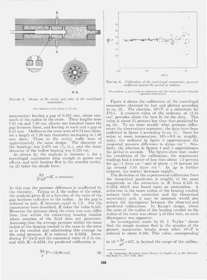
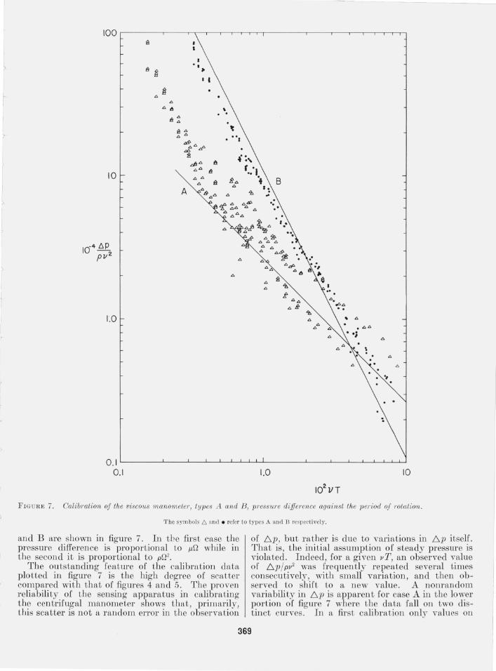
F IGURE 7. Cali bration oj the viscous manometer, types I t and B , pressure dijj'erence against the period oj I'otation.
The symbols /::,. and . refer to types A ane! B res pectively.
an d Bare s 110 wn in figure 7. In tb e firs t case the pressure difference is proportional to jJ.Q while in t he second it is proportional to pQ2.
The outstanding featme of the calibration datfl, plotted in figure 7 is the high degree of scatter compared with that of figmes 4 and 5. The proven reliability of the sensing apparatus in calibratin g the centrifugal manometer shows thfl,t , primarily, this scatter is not a random error in the ob ervation
of /::;.p, but rather is due to varifl,tions in /::;.p itself. That is , the initial assumption of steady pressure is violated . Indeed, for a given vT, an observed value of /::;.p / pv2 was frequently repeated several times consecu tively, with small variation , and then observed to shift to a new value. A nonrandom variabili ty in /::;.p is apparent for case A in the lower portion of figure 7 where the data fall on two distinct curves. In a first calibration only vnlues on
369

the lower curve were found, but in a second, some weeks later, values on both curves appeared. A general increase in the scatter of case B as 10 2vT is reduced below about 0.9, and a tendenc~' for the slope of case A to steepen below this same value, suggest some change in regime at this point, possibly a transiti.on to turbulen t flow. At least some of the yariation for higher values or 102vT migh t derive from cellular types of flow related to those between concentric cylinders and investigated by G. 1. Taylor . But however interpreted, the scatter in figure 7 demonstrates the failure of a viscous manometer of the presc ll L des ign.
It must also be noted , that because any change in the pattern of {Jow ill the CHyity requires the action of yiscous forces, the rotor response of this type of manometer is relatively slow. In the range of t he smaller pressure differences, the establish ment of n, llear steady stnte required from one to several minutes.
There may be other designs for a viscous manometer which would prove more successful. ] 11
the presen t case a reductio ll of the gap migh t reduce the scatter to an accepbtble degree. Alternative designs of simple geollletJ·~- 11l1d construction are readily conccived but these nre not investigated here.
7. Manometer Sensitivity
7.1. Effect of Circuit Resistance and Test Section Design
If the pressure 6,.p is not precisel.,- adjusted to 6,.p' , the imbalance, say op , is accompanied by a volume rfl te of flow through the system, sar oq , and in the illumin ated cross section, say of area A, there is an average velocity of flow ou equal to oq/A.
Tal.;:ing ou to be inversely proportional to the time, t, that a particle remflins within the t wo wire lines shoWJl in figure 2, and determining op by either of the two cali bration systems, i t was found that OV increflsed, approximatel~", ill proportioJl to op for any given combillation or man ometer and c<Llibratioll system. Further investigation, wi th the centrifugal manometer, confirmed tbat ov/op remained Ull
affected by Q.
Thus the flow through the system due to the pressure imbalance can be taken as laminar , and
! oP= AR jJ. oV (.5)
where R defines the resistance of the syste m to the flow oq, through it. Sin ce the smallest pressure which can be measured clepellds upon the smallest velocity which can be detected , the sensitivity of a manometer system increases with ou/op and, to maximize sensitivity, AR must be minimized. . Th~ design of. the conduit in the vicinity of the Illummated partIcles, tIle test section , determines A and greatly affects the sensitivity of a manometer system. Denoting by l' that part of the total
resistance R which is affected by the test section design, and by To the remainder, which may be assumed irreducible , t here is an optimum design which minimizes A (1' + 1'0). Any change in To, as by replacing one pi tot-static tube wiLh another, requires a new optimum design. In these investigations, different values of To correspond to different combinations of manometer and calibration system.
One practical approach to an optimum variable detector design is to vary the depth of the test section. In the case tested here, the glass walls or the test section were plane and parallel and fixed at Hs in. apart. Between the walls were fitted a fixed roof and a moveable floor of brass. Both were curved to give a minimum cross section at the plan e of illumination. These features are indicated in figure 2. Moving the floor up or down changed both A and l' and, consequen t ly, the sensitivity.
Figure 8 shows the observed variation of tlte sensitivity with depth of test section, for three values of To. The ordinate, top/jJ., is approximately proportional to 0p/jJ.ov , that is, inversely proportional to the sensitivity. The abscissa, Z, is the depth of t he test section. The solid lines (1, 2, 3) represen t A (1'+ 1'0) with values of To in the ratios 1 : 6 : 13 and with T a function of Z chosen best to fit the data . ",,\lhile this fit is not very close, the data show that , with increasing To, the sensitivity decreases and tbe value of Z for "optimum design" also decreases.
The test section depth was not made adjustable until after the manometer calibrations were COlll
pleted. During the calibrations it was constant at 0.062.5 in. (equal to the width of the section ), a value selected from a preliminary calculatioll. As seell in figure 8, varying degrees of sensitivi ty ,,"ere thereby sacrificed .
t8p }J-
o
8 0
C>
0
0 8 0
C>
0
0
0
0.01
8 o 8 " C>
I>
0
00 0
0
8
0 0
0
0.1
Z, in.
FIG U RE 8. 'Variation of sensitivity with depth of test section z, and resistance to flow, roo
On the curves (1 ,2,3) values of TO are in the ratio 1:6:13.
370
I l
/
J

I ;,
L r
l
)
r I J o
It is no ted tha t the resis tan ce of any elem en t in t he circuit can be de termin ed easily by conn ecting t he ends to open vessels of wa ter of differing head n,nd measuring the volume flo w in a givr n t ime.
7.2. Drift Errors and Corrections
E xperience showed tha t the [acLo.r lirnjting the ~ccuracy of the calibra ti ons was no t, l.~ general , an 111-ability to detect or bu t l" fLt her dni ts t hroug h t he system caused by vari ations in tempera ture . Presumably t hese drif ts ari se primfl:rily f~'om tempera,ture induced vari ations in the densi ty of t he water hom place to place in the system , and perhaps in par t fro~ differing ra tes of expansion of the s<?hd 1~1embe.rs of the system . In any case, bef:ore cahbratiOn , wI th Q and !:;p equal to zero, t1n~- drIi t observed t hroug h t he microscope could be elimin ated . This was done by a djustin g t he posi tion of th e elld of a w<"u'm copper rod between t he ver t ical clemen Ls of a U-shn,ped section of tb e cO lldui t. Th e rod wns heated by t he ligh t source which was 1l0<ll' iLs other ell d . . H owever , immediately a fte r n readin g- WIth /:::, p aga lll zero, a drift wn,s o I' Len o bser ved . This drif t implied an error op to be added to 01' s ub tnl,cted fro m /:::,p, and . whose magni tude w,.s given b~- t he k.no.wn valu e or top/u. , F or valu es of /:::,p ,1,bove some limit the dnf t COlTect ions were ill consequential but became cri tical as /:::,p wn,s l'educed to t he average magni t ude of op . Tn t he case of the cen trifugal m an ometer t hese limits were roug hly 1 d)Tne cm- 2 alld 1/10 d~Tn e CI11- 2. The m,.nometer syste m was pmtl~T ll1suia ted from the lIg ht source a nd was ve ntilated by a [an . No a t tempt was mad e to mcasure t he temperature field around t he rotOI' housing except to note tl~at temperat~re differences were too small to be rehably determm ed by a thermo meter wi th increments of 0 .10 C. H owever the a ddi t ion o f' the fa n was found to redu ce the drif t) correc tioll s m ad mdh- and fur ther attempts at tem -perature co n trol ma~' hold promise. . ..
The prob,.ble significance of a dnft correctIOn 111-creases wi th t he t ime required [01' the rea d111 g. Un fort unately, 1'01' t he Inanometers tes ted, th ere occurred ,), slig h t pulsing of the observed par tl c~es with each tUI'll of t he ro tor, presumably due to Irregularities in bearing fric tion combined ,yjth t he possibili ty of slip be tween the cones. A~ a res~lt , verification of no flow required an observatiOn lastlllg throug h several cycles, th.e peri~d of whi~l~ increased with decreasing /:::,p . ThIS pulsll1g, reqUl~·I.ng .longer readino's which allow the temperature drift tune to develop, was found to ?e the single factor most dam agin g to the convemence and n,ccuracy of t he cen tri[ugal m anometer .
8. Conclusions
There ar e man y possible designs [or a rota tio l.lal manometer that is, a meniscus free in strumen t win ch balances an' unknown pressure difference agai.n st the known action of a rotating element. On e deslg.n , the centrifugal m anometer , which had been prevIOusly
inves ti O'a ted a nd tested successfully in air, has I)een found l~ere to be n,lso s ui t,1,ble [or use in water. This type o( rotation al m.an on:ete ~· 11<1,s .several distinc t advantaO'es. Th e caltbrat lOn JS of sLmple (orm and, Iyjth cm':'crul de ign ,m d co nstru ction , c,),l1 b e predi cted , t.hat is, n o calibration is Il ecessar~T . 'rhe rotor r esponse of t he instruill ell t is ral? i d , .,wd the pressl1r~ difrerence produ ced by t he rotatlOlllS Inciepend: nt of t he molecular viscosity, so t be measure illell L o f t~mperature is unnecessary, The sin gle a lterna te deSIgn here inves tigated , the "viscous" I11n11 0 l11eter , .I~ad none of these advantages and, because of val'HLblli ty in the calibrations, proved unsuita ble. The (lowy atterns in the cavi ty upon which th e some what varmblc pressure differences depend are prob n, ?ly .co mplex n,nd dominated by viscous forces . 'WIlile Improv:~ments are possible, i t seems apparent tha t t he ce ~ tnl ugal m anometer is t he most satisfac tory of rotatIO nal nl,lIl 0 me tel's.
U ncler t he conditio ll s of calibra tion, t he centrifugal m a no meter gave readillgs repea table to wi t hin a bout ± 2 percent for /:::']»1 d~'ll e CI11- 2 a nd to ,Lbou t ± 10 percent 1'01' /:::,p around 1/10 dy ll e cm- 2 . lllll e,~, rly.all t he rcadings for /:::, p< lO dynes cm- 2 t he POlseUllle cfLlib ntt illg app,u atus W,l,S used . . Beca use t he two orifices ill th e sid e of t he P Olse llllle fl ow tube wer e small t he res istance of t his a pp,w .Lns was prob a bly hll'ge i t han t hat of m,Ln Y pi to t-static t ubes or likely dimensions and des ign. Therefo re t he ped orman ce under calib ra tio n was reason abl.\' close to tll<l, t wluch might be expected ullcl er norm ,.l ~peration ,
The sell siti vity of t he cent nfug ,1,l nt<1,110 Ineter tested ill w,l, te r 'co mpares f,l,vo mbly wi t h th at o f m.icroman o nlC Lers ill volvin g n fluid surface an~ls similar to that attain ed b ,\T mosL meillseus Iree m anometers used in n,ir. Th e smallest ci cteeblble pressure cliO'erell C'es . were roughly .Lwice, th ose. detectable by K emp's Ill stnull en t 1I1 al r. U? 111 pa I'lSO n of manonleLers [01' use ill diffe rent meetla by t he press lire differell ces th e~T ~H n. detect is som ewlllLt arbitrary, An alLel'llate cntel'lOIl IS t he percentage error in measurillO' with ,l, pi to t-s tat lc- tllbe, t he velocity \1 at a gi:~n poin t in :L ('o llduit r or a given R eyno.lds number. This.c,rrol' IS propol't21 0 lla~ to the error 111 the pressure chfIel'ence 1/2p 17 wluch, :: t room t emper n,ture, is a bout three tunes larger 111
water than in ail'. The sensitivitv of a rota tional m anometer, or the
errol' to which it l S li}tble, depends upon t he l'es istane~ of the circuit in which it opemtes. All 111('reHse ~[ the resistan ce of any elem ent decr eases the senSItivity, Therefore any n,nticipa tioll or probable error in actual operatlOn must rest ]lot only upon th e results o[ calibration but must n,lso comp tl,l'e t h~ r esistan ce of the calibra ting app itratus WIth that of th e elemen ts which are to replace it. A man~meter's sensitivity is also depende ~l t upon the deSign and dimension s o f the test sec tIOn Jll t l.e flow detec tor., Ideally, t he optimum design differs 1'01' e,l,cll val~e of the circuit resistan ce, On e approach to a van a ble desiO' n has been fo uncl practical.
b
(P aper 66C4- 1l2)
371