Embed Size (px)
Citation preview

Rotational Equilibrium 6-1
Rotational Equilibrium
INTRODUCTION
Have you ever tried to pull a stubborn nail out of a board or develop your forearm musclesby lifting weights? Both these activities involve using a “lever-type” action to produce a turningeffect or torque through the application of a force. The same torque can be produced by applyinga small force at a larger distance (with more leverage) or by applying a larger force closer to thepoint about which the object has to rotate. These two examples are shown in Fig. 1. In the case ofthe hammer pulling the nail, a small force applied at the end of the handle translates into a largerforce being exerted on the nail at a smaller distance from the point where the nail is fixed to theboard. In the second example the weight on the palm of the hand is at a greater distance fromthe elbow. This requires the muscles to apply a larger force at a smaller distance, usually less than5 cm from the elbow. These are both examples of lever action—force applied at a distance froma fulcrum or pivot point or axis of rotation. A force applied as described in the above examplesresults in a torque on a body. Torque usually produces a rotation of a body.
Figure 1: Two examples of torque
DISCUSSION OF PRINCIPLES
Torque1 is a measure of the turning effect of an applied force on an object, and is the rotationalanalogue to force. In translational motion, a net force causes an object to accelerate, while inrotational motion, a net torque causes an object to increase or decrease its rate of rotation. Torqueτ is the product of the applied force and the perpendicular distance from the pivot point to theline of action of the force and is measured in units of N·m.
1http://en.wikipedia.org/wiki/Torque
6-2 Mechanics
τ = Fr⊥ (1)
where r⊥ is sometimes called the “lever arm.”
Note: Torque has the same units as work, i.e., force times distance. Torque and work, however,are entirely different physical concepts; the fact that they have the same units is a coincidence.
Calculation of torque
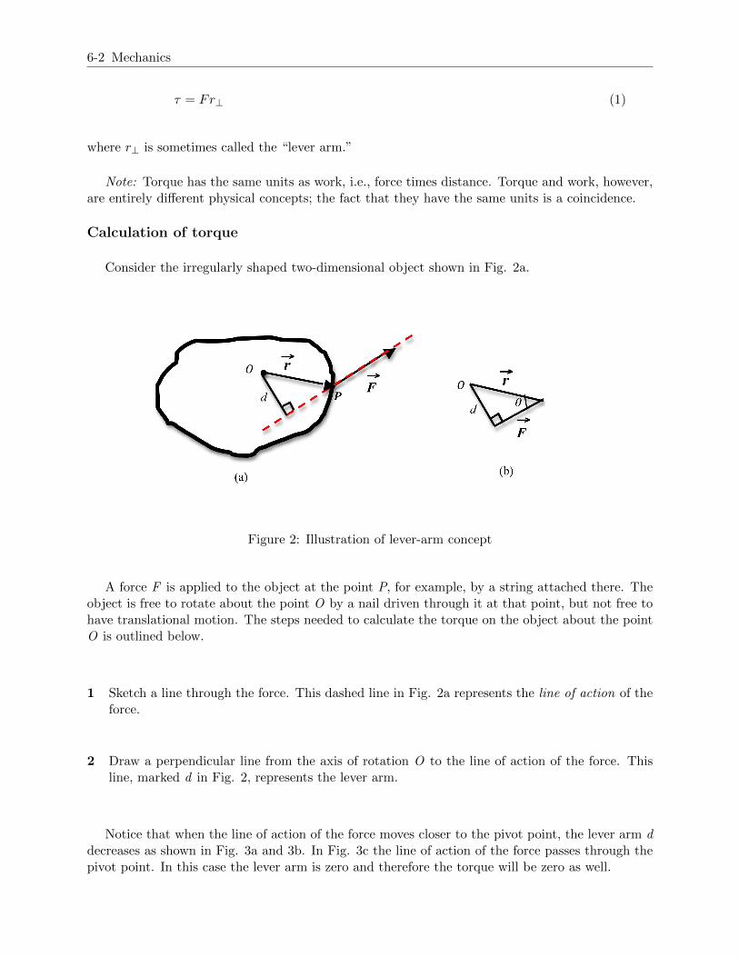
Consider the irregularly shaped two-dimensional object shown in Fig. 2a.
Figure 2: Illustration of lever-arm concept
A force F is applied to the object at the point P, for example, by a string attached there. Theobject is free to rotate about the point O by a nail driven through it at that point, but not free tohave translational motion. The steps needed to calculate the torque on the object about the pointO is outlined below.
1 Sketch a line through the force. This dashed line in Fig. 2a represents the line of action of theforce.
2 Draw a perpendicular line from the axis of rotation O to the line of action of the force. Thisline, marked d in Fig. 2, represents the lever arm.
Notice that when the line of action of the force moves closer to the pivot point, the lever arm ddecreases as shown in Fig. 3a and 3b. In Fig. 3c the line of action of the force passes through thepivot point. In this case the lever arm is zero and therefore the torque will be zero as well.

Rotational Equilibrium 6-3
Figure 3: Dependence of lever arm on point of application of force
Since the lever arm d makes a right angle with the line of action of the force, the three quantities,d, F, and r make a right triangle. This triangle has been redrawn in Fig. 2b. From this trianglewe see that the lever arm d is given by
d = r sin θ (2)
where θ is the angle between −→r and−→F . Equation (1) can now be written as
τ = rF sin θ. (3)
Using vector multiplication, this can also be expressed as the cross product2 of −→r and−→F
−→τ = −→r ×−→F . (4)
Net torque
If two or more forces are applied to an object, each force produces a torque. The rotation of thewheel shown in Fig. 4 is caused by the sum of the two torques.
2http://en.wikipedia.org/wiki/Cross product

6-4 Mechanics
Figure 4: A wheel experiencing two torques
By convention, torques causing counterclockwise rotations are considered to be positive andtorques causing clockwise rotations are negative. In the above example ~F1 will produce a positiveor counterclockwise torque, while ~F2 will produce a negative or clockwise torque. For rotationabout the center the magnitude of the net torque will be the algebraic sum of the two torques:
τtotal = F1d1 − F2d2. (5)
As mentioned above, torque is actually a vector. The torque vector is perpendicular to the plane
formed by the vectors −→r and−→F . The right-hand rule3 gives the direction of the cross product of
two vectors. Based on this rule positive torques, such as F1d1, are directed out of the page, whilenegative torques, such as F2d2, are directed into the page.
Definitions of equilibrium
Torque causes rotational motion with angular (or rotational) acceleration α,
τnet = Iα (6)
where I is the moment of inertia of the system and α is the angular acceleration. This equation isthe angular equivalent of Newton’s second law:
Fnet = ma. (7)
When the net torque is zero, the object will not change its state of rotational motion—i.e., itwill not start rotating or stop rotating or change the direction of its rotation. It is said to be inrotational equilibrium. If the sum of the forces acting on the object is also zero, the object is intranslational equilibrium and will not change its state of translational motion, that is, it will notspeed up or slow down or change its direction of motion. Whenever both of these conditions
3http://en.wikipedia.org/wiki/Right hand rule

Rotational Equilibrium 6-5
∑−→τ = 0 and∑−→
F = 0 (8)
are met, the object is said to be in static equilibrium.
OBJECTIVE
The objective of this experiment is to learn to measure torque due to a force and to adjust themagnitude of one or more forces and their lever arms to produce static equilibrium in a meter stickbalanced on a knife-edge; use the conditions for equilibrium to determine the mass of the meterstick and the mass of an unknown object.
EQUIPMENT
Meter stick
Knife-edge
Known masses of varying values
Unknown mass
Balance
PROCEDURE
There are three parts to this experiment. In the first part, you will balance three forces on ameter stick and show that the net torque is zero when the meter stick is in equilibrium. In thesecond part you will balance the weight of the meter stick against a known weight to determine themass of the meter stick. Finally you will use the principle of rotational equilibrium to determinethe mass of an unknown object.
All lever arm distances are measured from the knife-edge, which serves as the point of support.
You will be using rubber bands to hang the weights on the meter stick. Assume that the massesof the rubber bands are negligible.
Procedure A: Balancing Torques
1 Balance the meter stick on the knife-edge. The point at which the stick balances is the centerof gravity of the meter stick. Enter this value on the worksheet.
2 Select two 200-gram masses and one 100-gram mass.
3 Refer to Fig. 5 and Fig. 6. Place a hanger at the 20-cm mark, a distance x1 cm to the left ofthe center of gravity and place mass m1 = 200 g on it.
Place another hanger at the 65-cm mark, a distance x2 cm to the right of the center of gravityand place a mass m2 = 200 g on it.
Enter these values in Data Table 1.

6-6 Mechanics
Figure 5: Three balanced torques
Figure 6: Photo of experimental set up
4 Calculate the torques due to m1 and m2 and enter these values in Data Table 1. Be sure toinclude the sign of the torques.
5 Using the appropriate sign for each torque we can write the condition for rotational equilibriumas
∑τ = m1gx1 −m2gx2 −m3gx3 = 0 (9)
6 Use Eq. (9) and the values of the torques due to m1 and m2 to predict the torque due to m3
(including its sign) and enter this value in Data Table 1.
Be sure to include the sign of the torques.
7 Use the predicted value of the torque due to m3 to predict the position of x3 at which the thirdmass m3 must be placed to balance the meter stick. Record this value on the worksheet.
8 Experimentally determine the position x3 of m3 and enter this value on the worksheet.

Rotational Equilibrium 6-7
9 Compare the two values for the position x3 by finding the percent difference between thepredicted and experimental values of x3. See Appendix B.
CHECKPOINT 1: Ask your TA to check your set-up and calculations.
Procedure B: Finding the Mass of a Meter Stick
For this part of the experiment you will use a 200-gram mass, the meter stick and the knife-edge.
10 Move the knife-edge to the 25-cm mark.
You will notice that the meter stick is no longer in equilibrium. The unbalanced force is theweight of the meter stick at its center of gravity.
11 Experimentally find the position, x1 of the 200-gram mass, needed to balance the meter stick.Enter the value of x1 and its uncertainty on the worksheet.
12 In the space provided in the worksheet, sketch and carefully label a diagram of the meter stickand the 200-gram mass.
Show all the torque-producing forces. Remember that the weight of the meter stick acts at itscenter of gravity.
Indicate on your diagram the directions (clockwise or counterclockwise) of each torque.
13 Calculate the torque due to the 200-gram mass and enter this value in Data Table 2.
14 Use the value of the torque due to the 200-gram mass and the conditions for rotational equilib-rium to determine the torque due to the mass m2 of the meter stick. Enter this value in DataTable 2.
15 Using the value of the torque determined in step 14, calculate the value of the mass of the meterstick m2. Enter this value on the worksheet.
16 Calculate the uncertainty associated with the calculated mass and enter this value in the work-sheet. See Appendix C.
17 Determine the percent uncertainty in the calculated value of the mass of the meter stick.
18 Use the balance to measure the mass of the meter stick.
19 Calculate the percent uncertainty in the measured mass of the meter stick.
20 Compare the measured and calculated values of the mass of the meter stick by computing thepercent difference.
CHECKPOINT 2: Ask your TA to check your diagram, set-up, uncertainty formula, andcalculations.
Procedure C: Determining an Unknown Mass
6-8 Mechanics
21 Position the center of gravity of the meter stick over the support.
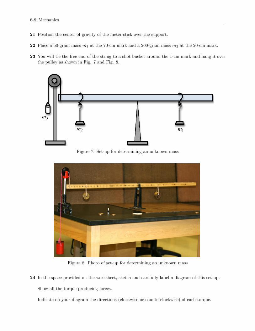
22 Place a 50-gram mass m1 at the 70-cm mark and a 200-gram mass m2 at the 20-cm mark.
23 You will tie the free end of the string to a shot bucket around the 1-cm mark and hang it overthe pulley as shown in Fig. 7 and Fig. 8.
Figure 7: Set-up for determining an unknown mass
Figure 8: Photo of set-up for determining an unknown mass
24 In the space provided on the worksheet, sketch and carefully label a diagram of this set-up.
Show all the torque-producing forces.
Indicate on your diagram the directions (clockwise or counterclockwise) of each torque.

Rotational Equilibrium 6-9
25 Calculate the torques due to m1 and m2, and enter these values in Data Table 3.
26 Use the values of the torques due to the two masses and the conditions for rotational equilibriumto determine the torque due to m3. Enter this value in Data Table 3.
27 Use the equation below to calculate the uncertainty in the predicted mass of m3.
σm3 =
√(σx3m3
x3
)2+(σm1x1x3
)2+(σx1m1
x3
)2+(σm2x2x3
)2+(σx2m2
x3
)2(10)
28 Calculate the percent uncertainty in the predicted mass of the shot plus bucket.
29 Now add small masses to the bucket until the stick balances.
30 Determine the mass m3 and the associated uncertainty of the shot and bucket using a balance.
31 Calculate the percent uncertainty in the experimental mass of the shot plus bucket.
32 Compute the percent difference between the experimental and predicted values for the mass ofthe shot plus bucket.
CHECKPOINT 3: Ask your TA to check your set-up, diagram and calculations.
Copyright c© 2011 Advanced Instructional Systems, Inc. and North Carolina State University Physics Department