Embed Size (px)
Citation preview

9-1
ROTATION OF RIGID BODIES
9.1. IDENTIFY: s r!" , with ! in radians.
SET UP: rad 180# " ! .
EXECUTE: (a) 1.50 m
0.600 rad 34.42.50 m
s
r! " " " " !
(b) 14.0 cm
6.27 cm(128 )( rad /180 )
sr
! #" " "
! !
(c) (1.50 m)(0.700 rad) 1.05 ms r!" " "
EVALUATE: An angle is the ratio of two lengths and is dimensionless. But, when s r!" is used, ! must be in
radians. Or, if /s r! " is used to calculate ! , the calculation gives ! in radians.
9.2. IDENTIFY: 0 t! ! $% " , since the angular velocity is constant.
SET UP: 1 rpm (2 / 60) rad/s#" .
EXECUTE: (a) (1900)(2 rad / 60 s) 199 rad/s$ #" "
(b) 35 (35 )( /180 ) 0.611 rad#" "! ! ! . 30 0.611 rad3.1 10 s
199 rad/st
! !$
%%" " " &
EVALUATE: In 0t! !$%
" we must use the same angular measure (radians, degrees or revolutions) for both
0! !% and $ .
9.3. IDENTIFY: ( ) zz
dt
dt
$' " . Writing Eq.(2.16) in terms of angular quantities gives
2
1
t
zt
dt! ! $% " ( .
SET UP: 1n ndt nt
dt
%" and 11
1
n nt dt tn
)")(
EXECUTE: (a) A must have units of rad/s and B must have units of 3rad/s .
(b) 3( ) 2 (3.00 rad/s )z t Bt t' " " . (i) For 0t " , 0z' " . (ii) For 5.00 st " , 215.0 rad/sz' " .
(c) 2
1
2 3 312 1 2 1 2 13
( ) ( ) ( )t
tA Bt dt A t t B t t! !% " ) " % ) %( . For 1 0t " and 2 2.00 st " ,
3 312 1 3
(2.75 rad/s)(2.00 s) (1.50 rad/s )(2.00 s) 9.50 rad! !% " ) " .
EVALUATE: Both z' and z$ are positive and the angular speed is increasing.
9.4. IDENTIFY: /z zd dt' $" . av-z
zt
$'
*"
*.
SET UP: 2( ) 2d
t tdt
"
EXECUTE: (a) 3( ) 2 ( 1.60 rad s ) .zz
d!" t #t t
dt" " % " %
(b) 3 2(3.0 s) ( 1.60 rad s )(3.0 s) 4.80 rad s .z" " % " %
2.
av-
(3.0 s) (0) 2.20 rad s 5.00 rad s2.40 rad s ,
3.0 s 3.0 s
z zz
! !"
% % %" " " %
which is half as large (in magnitude) as the acceleration at 3.0 s.t "
EVALUATE: ( )z t' increases linearly with time, so av-
(0) (3.0 s)
2
z zz
' ''
)" . (0) 0z' " .
9

9-2 Chapter 9
9.5. IDENTIFY and SET UP: Use Eq.(9.3) to calculate the angular velocity and Eq.(9.2) to calculate the average
angular velocity for the specified time interval.
EXECUTE: 3;t t! + ," ) 0.400 rad/s,+ " 30.0120 rad/s, "
(a) 23z
dt
dt
!$ + ," " )
(b) At 0,t " 0.400 rad/sz$ +" "
(c) At 5.00 s,t " 3 20.400 rad/s 3(0.0120 rad/s )(5.00 s) 1.30 rad/sz$ " ) "
2 1av-
2 1
zt t t
! ! !$
* %" "* %
For 1 0,t " 1 0.! "
For 2 5.00 s,! " 3 3
2 (0.400 rad/s)(5.00 s) (0.012 rad/s )(5.00 s) 3.50 rad! " ) "
So av-
3.50 rad 00.700 rad/s.
5.00 s 0z$
%" "
%
EVALUATE: The average of the instantaneous angular velocities at the beginning and end of the time interval is 12(0.400 rad/s 1.30 rad/s) 0.850 rad/s.) " This is larger than av- ,z$ because ( )z t$ is increasing faster than linearly.
9.6. IDENTIFY: ( )z
dt
dt
!$ " . ( ) z
z
dt
dt
$' " . av-z
t
!$
*"*
.
SET UP: 2 3 2(250 rad s) (40.0 rad s ) (4.50 rad s )z! t t" % % . 2 3
z (40.0 rad s ) (9.00 rad s )" t" % % .
EXECUTE: (a) Setting 0z! " results in a quadratic in t. The only positive root is 4.23 st " .
(b) At 4.23 st " , 278.1 rad s .z" " %
(c) At 4.23 st " , 586 rad 93.3 rev$ " " .
(d) At 0t " , 250 rad/sz! " .
(e) av-586 rad 138 rad s.4.23 sz$ " "
EVALUATE: Between 0t " and 4.23 st " , z$ decreases from 250 rad/s to zero. z$ is not linear in t, so av-z$ is
not midway between the values of z$ at the beginning and end of the interval.
9.7. IDENTIFY: ( )z
dt
dt
!$ " . ( ) z
z
dt
dt
$' " . Use the values of ! and z$ at 0t " and z' at 1.50 s to calculate a, b,
and c.
SET UP: 1n ndt nt
dt
%"
EXECUTE: (a) 2( ) 3z t b ct$ " % . ( ) 6z t ct' " % . At 0t " , / 4 rada! #" " and 2.00 rad/sz b$ " " . At 1.50 st " ,
26 (1.50 s) 1.25 rad/sz c' " % " and 30.139 rad/sc " % .
(b) / 4 rad! #" and 0z' " at 0t " .
(c) 23.50 rad/sz' " at
2
3
3.50 rad/s4.20 s
6 6( 0.139 rad/s )
ztc
'" % " % "
%. At 4.20 st " ,
3 3 rad (2.00 rad/s)(4.20 s) ( 0.139 rad/s )(4.20 s) 19.5 rad4
#! " ) % % " .
3 22.00 rad/s 3( 0.139 rad/s )(4.20 s) 9.36 rad/sz$ " % % " .
EVALUATE: ! , z$ and z' all increase as t increases.
9.8. IDENTIFY: zz
d
dt
$' " . 0 av-zt! ! $% " . When z$ is linear in t, av-z$ for the time interval 1t to 2t is
1 2av-
2 1
z zz
t t
$ $$
)"
%.
SET UP: From the information given, 2( ) 6.00 rad/s (2.00 rad/s )z t t$ " % )
EXECUTE: (a) The angular acceleration is positive, since the angular velocity increases steadily from a negative
value to a positive value.
(b) It takes 3.00 seconds for the wheel to stop ( 0)z! " . During this time its speed is decreasing. For the next
4.00 s its speed is increasing from 0 rad s to 8.00 rad s) .

Rotation of Rigid Bodies 9-3
(c) The average angular velocity is 6.00 rad s 8.00 rad s
1.00 rad s2
% )" . 0 av-zt! ! $% " then leads to
displacement of 7.00 rad after 7.00 s.
EVALUATE: When z' and z$ have the same sign, the angular speed is increasing; this is the case for 3.00 st " to
7.00 st " . When z' and z$ have opposite signs, the angular speed is decreasing; this is the case between
0t " and 3.00 st " .
9.9. IDENTIFY: Apply the constant angular acceleration equations.
SET UP: Let the direction the wheel is rotating be positive.
EXECUTE: (a) 2
0 1.50 rad s (0.300 rad s )(2.50 s) 2.25 rad s.z z zt$ $ '" ) " ) "
(b) 2 2 21 10 0 2 2
(1.50 rad/s)(2.50 s) (0.300 rad/s )(2.50 s) 4.69 radz zt t! ! $ '% " ) " ) " .
EVALUATE: 00
1.50 rad/s 2.25 rad/s(2.50 s) 4.69 rad
2 2
z z t$ $
! !) )- . - .% " " "/ 0 / 0
1 2 1 2, the same as calculated with
another equation in part (b).
9.10. IDENTIFY: Apply the constant angular acceleration equations to the motion of the fan.
(a) SET UP: 0 (500 rev/min)(1 min/60 s) 8.333 rev/s,z$ " " (200 rev/min)(1 min/60 s) 3.333 rev/s,z$ " "
4.00 s,t " ?z' "
0z z zt$ $ '" )
EXECUTE: 20 3.333 rev/s 8.333 rev/s1.25 rev/s
4.00 s
z zz
t
$ $'
% %" " " %
0 ?! !% "
2 2 21 10 0 2 2
(8.333 rev/s)(4.00 s) ( 1.25 rev/s )(4.00 s) 23.3 revz zt t! ! $ '% " ) " ) % "
(b) SET UP: 0z$ " (comes to rest); 0 3.333 rev/s;z$ " 21.25 rev/s ;z' " %
?t "
0z z zt$ $ '" )
EXECUTE: 0
2
0 3.333 rev/s2.67 s
1.25 rev/s
z z
z
t$ $'% %
" " "%
EVALUATE: The angular acceleration is negative because the angular velocity is decreasing. The average angular
velocity during the 4.00 s time interval is 350 rev/min and 0 av-zt! ! $% " gives 0 23.3 rev,! !% " which checks.
9.11. IDENTIFY: Apply the constant angular acceleration equations to the motion. The target variables are t and 0.! !%
SET UP: (a) 21.50 rad/s ;z' " 0 0z$ " (starts from rest); 36.0 rad/s;z$ " ?t "
0z z zt$ $ '" )
EXECUTE: 0
2
36.0 rad/s 024.0 s
1.50 rad/s
z z
z
t$ $'% %
" " "
(b) 0 ?! !% "
2 2 21 10 0 2 2
0 (1.50 rad/s )(2.40 s) 432 radz zt t! ! $ '% " ) " ) "
0 432 rad(1 rev/2 rad) 68.8 rev! ! #% " "
EVALUATE: We could use 10 02
( )z z t! ! $ $% " ) to calculate 10 2
(0 36.0 rad/s)(24.0 s) 432 rad,! !% " ) " which
checks.
9.12. IDENTIFY: In part (b) apply the equation derived in part (a).
SET UP: Let the direction the propeller is rotating be positive.
EXECUTE: (a) Solving Eq. (9.7) for t gives 0z z
z
t$ $'%
" . Rewriting Eq. (9.11) as 10 0 2
( )z zt t! ! $ $% " ) and
substituting for t gives
2 20 00 0 0 0 0
1 1 1( ) ( ) ( ),
2 2 2
z z z zz z z z z z z
z z z
$ $ $ $! ! $ $ $ $ $ $ $
' ' '- .% )- . - .% " ) % " % " %/ 0/ 0 / 0
1 2 1 21 2
which when rearranged gives Eq. (9.12).
(b) 3 4 3 4 3 43 42 22 2 21 102 2
0
1 116.0 rad s 12.0 rad s 8.00 rad/s
7.00 radz z z' $ $
! !- . - ." % " % "/ 0 / 0% 1 21 2

9-4 Chapter 9
EVALUATE: We could also use 00
2
z z t$ $
! !)- .% " / 0
1 2to calculate 0.500 st " . Then 0z z zt$ $ '" ) gives
28.00 rad/sz' " , which agrees with our results in part (b).
9.13. IDENTIFY: Use a constant angular acceleration equation and solve for 0 .z$
SET UP: Let the direction of rotation of the flywheel be positive.
EXECUTE: 21
0 0 2z zt! ! $ '% " ) gives 20 1 10 2 2
60.0 rad(2.25 rad/s )(4.00 s) 10.5 rad/s
4.00 sz z
t
! !$ '
%" % " % " .
EVALUATE: At the end of the 4.00 s interval, 0 19.5 rad/sz z zt$ $ '" ) " .
00
10.5 rad/s 19.5 rad/s(4.00 s) 60.0 rad
2 2
z z t$ $
! !) )- . - .% " " "/ 0 / 0
1 2 1 2, which checks.
9.14. IDENTIFY: Apply the constant angular acceleration equations.
SET UP: Let the direction of the rotation of the blade be positive. 0 0z$ " .
EXECUTE: 0z z z$ $ '" ) gives 20 140 rad/s 023.3 rad/s
6.00 s
z zz
t
$ $'
% %" " " .
00
0 140 rad/s( ) (6.00 s) 420 rad
2 2
z z t$ $
! !) )- . - .% " " "/ 0 / 0
1 2 1 2
EVALUATE: We could also use 210 0 2z zt t! ! $ '% " ) . This equation gives
2 210 2
(23.3 rad/s )(6.00 s) 419 rad! !% " " , in agreement with the result obtained above.
9.15. IDENTIFY: Apply constant angular acceleration equations.
SET UP: Let the direction the flywheel is rotating be positive.
0 0200 rev, 500 rev min 8.333 rev s, 30.0 sz t! ! $% " " " " .
EXECUTE: (a) 00 gives 5.00 rev s 300 rpm
2
z zzt
$ $! ! $
)- .% " " "/ 01 2
(b) Use the information in part (a) to find :z' 0z z zt$ $ '" ) gives 20.1111 rev sz' " % . Then 0,z$ "
2
00.1111 rev s , 8.333 rev sz z' $" % " in 0z z zt$ $ '" ) gives 75.0 st " and 00
2
z z t$ $
! !)- .% " / 0
1 2gives
0 312 rev! !% " .
EVALUATE: The mass and diameter of the flywheel are not used in the calculation.
9.16. IDENTIFY: Use the constant angular acceleration equations, applied to the first revolution and to the first two
revolutions.
SET UP: Let the direction the disk is rotating be positive. 1 rev 2 rad#" . Let t be the time for the first revolution.
The time for the first two revolutions is 0.750 st ) .
EXECUTE: (a) 21
0 0 2z zt t! ! $ '% " ) applied to the first and to the first two revolutions gives 212
2 rad zt# '" and
212
4 rad ( 0.750 s)z t# '" ) . Eliminating z' between these equations gives 2
2
2 rad4 rad ( 0.750 s)t
t
## " ) .
2 22 ( 0.750 s)t t" ) . 2 ( 0.750 s)t t" 5 ) . The positive root is 0.750 s
1.81 s2 1
t " "%
.
(b) 21
22 rad zt# '" and 1.81 st " gives 23.84 rad/sz' "
EVALUATE: At the start of the second revolution, 2
0 (3.84 rad/s )(1.81 s) 6.95 rad/sz$ " " . The distance the disk
rotates in the next 0.750 s is 2 2 21 10 0 2 2
(6.95 rad/s)(0.750 s) (3.84 rad/s )(0.750 s) 6.29 radz zt t! ! $ '% " ) " ) " ,
which is two revolutions.
9.17. IDENTIFY: Apply Eq.(9.12) to relate z$ to 0! !% .
SET UP: Establish a proportionality.
EXECUTE: From Eq.(9.12), with 0 0, z$ " the number of revolutions is proportional to the square of the initial
angular velocity, so tripling the initial angular velocity increases the number of revolutions by 9, to 9.00 rev.
EVALUATE: We don't have enough information to calculate z' ; all we need to know is that it is constant.

Rotation of Rigid Bodies 9-5
9.18. IDENTIFY: In each case we apply constant acceleration equations to determine ( )t! and ( )z t$ .
SET UP: Let 0 0! " . The following table gives the revolutions and the angle ! (in degrees) through which the
wheel has rotated for each instant in time (in seconds) and each of the three situations:
t (a)
rev !
(b)
rev !
(c)
rev !
0.05 0.50 180 0.03 11.3 0.44 158
0.10 1.00 360 0.13 45 0.75 270
0.15 1.50 540 0.28 101 0.94 338
0.20 2.00 720 0.50 180 1.00 360
EXECUTE: The ! and z$ graphs for each case are given in Figures 9.18 a�c.
EVALUATE: The slope of the ( )t! graph is ( )z t$ and the slope of the ( )z t$ graph is ( )z t' .
Figure 9.18

9-6 Chapter 9
9.19. IDENTIFY: Apply the constant angular acceleration equations separately to the time intervals 0 to 2.00 s and
2.00 s until the wheel stops.
(a) SET UP: Consider the motion from 0t " to 2.00 s:t "
0 ?;! !% " 0 24.0 rad/s;z$ " 230.0 rad/s ;z' " 2.00 st "
EXECUTE: 2 2 21 1
0 0 2 2(24.0 rad/s)(2.00 s) (30.0 rad/s )(2.00 s)z zt t! ! $ '% " ) " )
0 48.0 rad 60.0 rad 108 rad! !% " ) "
Total angular displacement from 0t " until stops: 108 rad 432 rad 540 rad) "
Note: At 2.00 s,t " 2
0 24.0 rad/s (30.0 rad/s )(2.00 s) 84.0 rad/s;z z zt$ $ '" ) " ) " angular speed when breaker trips.
(b) SET UP: Consider the motion from when the circuit breaker trips until the wheel stops. For this calculation let
0t " when the breaker trips.
?;t " 0 432 rad;! !% " 0;z$ " 0 84.0 rad/sz$ " (from part (a))
00
2
z z t$ $
! !)- .% " / 0
1 2
EXECUTE: 0
0
2( ) 2(432 rad)10.3 s
84.0 rad/s 0z z
t! !
$ $%
" " ") )
The wheel stops 10.3 s after the breaker trips so 2.00 s 10.3 s 12.3 s) " from the beginning.
(c) SET UP: ?;z' " consider the same motion as in part (b):
0z z zt$ $ '" )
EXECUTE: 20 0 84.0 rad/s8.16 rad/s
10.3 s
z zz
t
$ $'
% %" " " %
EVALUATE: The angular acceleration is positive while the wheel is speeding up and negative while it is slowing
down. We could also use 2 2
0 02 ( )z z z$ $ ' ! !" ) % to calculate 2 2 2
20
0
0 (84.0 rad/s)8.16 rad/s
2( ) 2(432 rad)
z zz
$ $'
! !% %
" " " %%
for
the acceleration after the breaker trips.
9.20. IDENTIFY: The linear distance the elevator travels, its speed and the magnitude of its acceleration are equal to the
tangential displacement, speed and acceleration of a point on the rim of the disk. s r!" , v r$" and a r'" . In
these equations the angular quantities must be in radians.
SET UP: 1 rev 2 rad#" . 1 rpm 0.1047 rad/s" . rad 180# " ! . For the disk, 1.25 mr " .
EXECUTE: (a) 0.250 m/sv " so 0.250 m/s
0.200 rad/s 1.91 rpm1.25 m
v
r$ " " " " .
(b) 21
81.225 m/sa g" " .
221.225 m/s
0.980 rad/s1.25 m
a
r' " " " .
(c) 3.25 ms " . 3.25 m
2.60 rad 1491.25 m
s
r! " " " " ! .
EVALUATE: When we use s r!" , v r$" and tana r'" to solve for ! , $ and ' , the results are in rad, rad/s
and 2rad/s .
9.21. IDENTIFY: When the angular speed is constant, / t$ !" . tanv r$" , tana r'" and 2
rada r$" . In these equations
radians must be used for the angular quantities.
SET UP: The radius of the earth is 6
E 6.38 10 mR " & and the earth rotates once in 1 day 86,400 s" . The orbit radius
of the earth is 111.50 10 m& and the earth completes one orbit in 71 y 3.156 10 s" & . When $ is constant, / t$ !" .
EXECUTE: (a) 1 rev 2 rad! #" " in 73.156 10 st " & . 7
7
2 rad1.99 10 rad/s
3.156 10 s
#$ %" " &
&.
(b) 1 rev 2 rad! #" " in 86,400 st " . 52 rad7.27 10 rad/s
86,400 s
#$ %" " &
(c) 11 7 4(1.50 10 m)(1.99 10 rad/s) 2.98 10 m/sv r$ %" " & & " & .
(d) 6 5(6.38 10 m)(7.27 10 rad/s) 464 m/sv r$ %" " & & " .
(e) 2 6 5 2 2
rad (6.38 10 m)(7.27 10 rad/s) 0.0337 m/sa r$ %" " & & " . tan 0a r'" " . 0' " since the angular velocity is
constant.
EVALUATE: The tangential speeds associated with these motions are large even though the angular speeds are
very small, because the radius for the circular path in each case is quite large.

Rotation of Rigid Bodies 9-7
9.22. IDENTIFY: Linear and angular velocities are related by v r$" . Use 0z z zt$ $ '" ) to calculate z' .
SET UP: /v r$ " gives$ in rad/s.
EXECUTE: (a) 3
1.25 m/s50.0 rad/s,
25.0 10 m%"
&
3
1.25 m/s21.6 rad/s.
58.0 10 m%"
&
(b) (1.25 m/s) (74.0 min) (60 s/min) " 5.55 km.
(c) 3 221.55 rad/s 50.0 rad/s 6.41 10 rad/s .
(74.0 min) (60 s/min)z'%%" " % &
EVALUATE: The width of the tracks is very small, so the total track length on the disc is huge.
9.23. IDENTIFY: Use constant acceleration equations to calculate the angular velocity at the end of two revolutions.
v r$" .
SET UP: 2 rev 4 rad.#" 0.200 m.r "
EXECUTE: (a) 2 2
0 02 ( ).z z z$ $ ' ! !" ) % 2
02 ( ) 2(3.00 rad/s )(4 rad) 8.68 rad/s.z z$ ' ! ! #" % " "
2 2 2
rad (0.200 m)(8.68 rad/s) 15.1 m/s .a r$" " "
(b) (0.200 m)(8.68 rad/s) 1.74 m/s.v r$" " " 2 2
2
rad
(1.74 m/s)15.1 m/s .
0.200 m
va
r" " "
EVALUATE: 2r$ and 2 /v r are completely equivalent expressions for rada .
9.24. IDENTIFY: 2
rada r$" , with $ in rad/s. Solve for $ .
SET UP: 1 rpm (2 / 60) rad/s#"
EXECUTE: 2
4 5rad (400,000)(9.80 m/s )1.25 10 rad/s 1.20 10 rpm
0.0250 m
a
r$ " " " & " &
EVALUATE: In 2
rada r$" , $ must be in rad/s.
9.25. IDENTIFY and SET UP: Use constant acceleration equations to find $ and ' after each displacement. The use
Eqs.(9.14) and (9.15) to find the components of the linear acceleration.
EXECUTE: (a) at the start 0t "
flywheel starts from rest so 0 0z z$ $" "
2 2
tan (0.300 m)(0.600 rad/s ) 0.180 m/sa r'" " "
2
rad 0a r$" "
2 2 2
rad tan 0.180 m/sa a a" ) "
(b) 0 60! !% " 6
2
tan 0.180 m/sa r'" "
Calculate :$
0 60 ( rad/180 ) 1.047 rad;! ! #% " 6 6 " 0 0;z$ " 20.600 rad/s ;z' " ?z$ "
2 2
0 02 ( )z z z$ $ ' ! !" ) %
2
02 ( ) 2(0.600 rad/s )(1.047 rad) 1.121 rad/sz z$ ' ! !" % " " and .z$ $"
Then 2 2 2
rad (0.300 m)(1.121 rad/s) 0.377 m/s .a r$" " "
2 2 2 2 2 2 2
rad tan (0.377 m/s ) (0.180 m/s ) 0.418 m/sa a a" ) " ) "
(c) 0 120! !% " 6
2
tan 0.180 m/sa r'" "
Calculate :$
0 120 ( rad/180 ) 2.094 rad;! ! #% " 6 6 " 0 0;z$ " 20.600 rad/s ;z' " ?z$ "
2 2
0 02 ( )z z z$ $ ' ! !" ) %
2
02 ( ) 2(0.600 rad/s )(2.094 rad) 1.585 rad/sz z$ ' ! !" % " " and .z$ $"
Then 2 2 2
rad (0.300 m)(1.585 rad/s) 0.754 m/s .a r$" " "
2 2 2 2 2 2 2
rad tan (0.754 m/s ) (0.180 m/s ) 0.775 m/sa a a" ) " ) "
EVALUATE: ' is constant so tan' is constant. $ increases so rada increases.

9-8 Chapter 9
9.26. IDENTIFY: Apply constant angular acceleration equations. v r$" . A point on the rim has both tangential and
radial components of acceleration.
SET UP: tana r'" and 2
rada r$" .
EXECUTE: (a)2
0 = 0.250 rev/s (0.900 rev/s )(0.200 s) 0.430 rev/sz z zt$ $ '" ) ) "
(Note that since 0 z$ and z' are given in terms of revolutions, it�s not necessary to convert to radians).
(b) av- (0.340 rev s)(0.2 s) 0.068 revz t$ * " " .
(c) Here, the conversion to radians must be made to use Eq. (9.13), and
3 43 40.750 m0.430 rev/s 2 rad rev 1.01 m s.
2v r$ #- ." " "/ 0
1 2
(d) Combining equations (9.14) and (9.15),
2 2 2 2 2
rad tan ( ) ( )a a a r r$ '" ) " ) .
2 22 2((0.430 rev/s)(2 rad/rev)) (0.375 m) (0.900 rev/s )(2 rad/rev)(0.375 m)a # #7 8 7 8" )9 : 9 : .
23.46 m sa " .
EVALUATE: If the angular acceleration is constant, tana is constant but rada increases as $ increases.
9.27. IDENTIFY: Use Eq.(9.15) and solve for r.
SET UP: 2
rada r$" so 2
rad / ,r a $" where $ must be in rad/s
EXECUTE: 2 2
rad 3000 3000(9.80 m/s ) 29,400 m/sa g" " "
1 min 2 rad(5000 rev/min) 523.6 rad/s
60 s 1 rev
#$ - .- ." "/ 0/ 0
1 21 2
Then 2
rad
2 2
29,400 m/s0.107 m.
(523.6 rad/s)
ar
$" " "
EVALUATE: The diameter is then 0.214 m, which is larger than 0.127 m, so the claim is not realistic.
9.28. IDENTIFY: In part (b) apply the result derived in part (a).
SET UP: 2
rada r$" and v r$" ; combine to eliminate r.
EXECUTE: (a) 2 2
rad = .v
a r v$ $ $$- ." "/ 01 2
(b) From the result of part (a), 2
rad 0.500 m s0.250 rad s.
2.00 m s
a
v$ " " "
EVALUATE: 2
rada r$" and v r$" both require that $ be in rad/s, so in rada v$" , $ is in rad/s.
9.29. IDENTIFY: v r$" and 2 2
rad /a r v r$" " .
SET UP: 2 rad 1 rev# " , so rad/s 30 rev/min# " .
EXECUTE: (a) 3 4312.7 10 m rad/s(1250 rev min ) 0.831 m s.
30 rev/min 2r #$
%- .&" "/ 0
1 2
(b) 2 2
2
3
(0.831 m s)109 m s .
(12.7 10 m) 2
v
r %" "
&
EVALUATE: In v r$" , $ must be in rad/s.
9.30. IDENTIFY: tana r'" , v r$" and 2
rad /a v r" . 0 av-zt! ! $% " .
SET UP: When z' is constant, 0av-
2
z zz
$ $$
)" . Let the direction the wheel is rotating be positive.
EXECUTE: (a) 2
2tan 10.0 m s50.0 rad s
0.200 m
a
r'
%" " " %
(b) At 3.00 st " , 50.0 m sv " and 50.0 m s
250 rad s0.200 m
v
r$ " " " and at 0,t "
250.0 m s ( 10.0 m s )(0 3.00 s) 80.0 m sv " ) % % " , 400 rad s.$ "
(c) av- (325 rad s)(3.00 s) 975 rad 155 revzt$ " " " .

Rotation of Rigid Bodies 9-9
(d) 2
rad (9.80 m/s )(0.200 m) 1.40 m/s.v a r" " " This speed will be reached at time 50.0 m/s 1.40 m/s
4.86 s10.0 m/s
%"
after 3.00 st " , or at 7.86 st " . (There are many equivalent ways to do this calculation.)
EVALUATE: At 0t " , 2 4 2
rad 3.20 10 m/sa r$" " & . At 3.00 st " , 4 2
rad 1.25 10 m/sa " & . For rada g" the wheel
must be rotating more slowly than at 3.00 s so it occurs some time after 3.00 s.
9.31. IDENTIFY and SET UP: Use Eq.(9.15) to relate $ to rada and m";F a!
!
to relate rada to rad.F Use Eq.(9.13) to
relate $ and v, where v is the tangential speed.
EXECUTE: (a) 2
rada r$" and 2
rad radF ma mr$" "
2 2
rad,2 2
rad,1 1
640 rev/min2.29
423 rev/min
F
F
$$- . - ." " "/ 0 / 0
1 21 2
(b) v r$"
2 2
1 1
640 rev/min1.51
423 rev/min
v
v
$$
" " "
(c) v r$"
1 min 2 rad(640 rev/min) 67.0 rad/s
60 s 1 rev
#$ - .- ." "/ 0/ 0
1 21 2
Then (0.235 m)(67.0 rad/s) 15.7 m/s.v r$" " "
2 2 2
rad (0.235 m)(67.0 rad/s) 1060 m/sa r$" " "
2
rad
2
1060 m/s108;
9.80 m/s
a
g" " 108a g"
EVALUATE: In parts (a) and (b), since a ratio is used the units cancel and there is no need to convert $ to rad/s.
In part (c), v and rada are calculated from ,$ and $ must be in rad/s.
9.32. IDENTIFY: v r$" and tana r'" .
SET UP: The linear acceleration of the bucket equals tana for a point on the rim of the axle.
EXECUTE: (a) v R$" . 7.5 rev 1 min 2 rad
2.00 cm s min 60 s 1 rev
R#- .- .- ." / 0/ 0/ 0
1 21 21 2 gives 2.55 cmR " .
2 5.09 cmD R" " .
(b) tana R'" . 2
2tan 0.400 m s15.7 rad s
0.0255 m
a
R' " " " .
EVALUATE: In v R$" and tana R'" , $ and ' must be in radians.
9.33. IDENTIFY: Apply v r$" .
SET UP: Points on the chain all move at the same speed, so r r f fr r$ $" .
EXECUTE: The angular velocity of the rear wheel is rr
5.00 m s15.15 rad s.
0.330 m
v
r$ " " "
The angular velocity of the front wheel is f 0.600 rev s 3.77 rad s$ " " . 3 4r f f r 2.99 cmr r $ $" " .
EVALUATE: The rear sprocket and wheel have the same angular velocity and the front sprocket and wheel have
the same angular velocity. r$ is the same for both, so the rear sprocket has a smaller radius since it has a larger
angular velocity. The speed of a point on the chain is 2
r r (2.99 10 m)(15.15 rad/s) 0.453 m/sv r$ %" " & " . The linear
speed of the bicycle is 5.50 m/s.
9.34. IDENTIFY and SET UP: Use Eq.(9.16). Treat the spheres as point masses and ignore I of the light rods.
EXECUTE: The object is shown in Figure 9.34a.
(a)
2 2(0.200 m) (0.200 m) 0.2828 mr " ) "
2 24(0.200 kg)(0.2828 m)i iI m r" ";
20.0640 kg mI " <
Figure 9.34a

9-10 Chapter 9
(b) The object is shown in Figure 9.34b.
0.200 mr " 2 24(0.200 kg)(0.200 m)i iI m r" ";
20.0320 kg mI " <
Figure 9.34b
(c) The object is shown in Figure 9.34c.
0.2828 mr " 2 22(0.200 kg)(0.2828 m)i iI m r" ";
20.0320 kg mI " <
Figure 9.34c
EVALUATE: In general I depends on the axis and our answer for part (a) is larger than for parts (b) and (c). It just
happens that I is the same in parts (b) and (c).
9.35. IDENTIFY: Use Table 9.2. The correct expression to use in each case depends on the shape of the object and the
location of the axis.
SET UP: In each case express the mass in kg and the length in m, so the moment of inertia will be in 2kg m< .
EXECUTE: (a) (i) 2 2 21 13 3
(2.50 kg)(0.750 m) 0.469 kg mI ML" " " < .
(ii) 2 2 21 112 4
(0.469 kg m ) 0.117 kg mI ML" " < " < . (iii) For a very thin rod, all of the mass is at the axis and 0I " .
(b) (i) 2 2 22 25 5
(3.00 kg)(0.190 m) 0.0433 kg mI MR" " " < .
(ii) 2 2 2523 3
(0.0433 kg m ) 0.0722 kg mI MR" " < " < .
(c) (i) 2 2 2(8.00 kg)(0.0600 m) 0.0288 kg mI MR" " " < .
(ii) 2 2 21 12 2
(8.00 kg)(0.0600 m) 0.0144 kg mI MR" " " < .
EVALUATE: I depends on how the mass of the object is distributed relative to the axis.
9.36. IDENTIFY: Treat each block as a point mass, so for each block 2I mr" , where r is the distance of the block from
the axis. The total I for the object is the sum of the I for each of its pieces.
SET UP: In part (a) two blocks are a distance / 2L from the axis and the third block is on the axis. In part (b) two
blocks are a distance / 4L from the axis and one is a distance 3 / 4L from the axis.
EXECUTE: (a) 2 21
22 ( / 2)I m L mL" " .
(b) 2 2 2 21 112 ( / 4) (3 / 4) (2 9)
16 16I m L m L mL mL" ) " ) " .
EVALUATE: For the same object I is in general different for different axes.
9.37. IDENTIFY: I for the object is the sum of the values of I for each part.
SET UP: For the bar, for an axis perpendicular to the bar, use the appropriate expression from Table 9.2. For a
point mass, 2I mr" , where r is the distance of the mass from the axis.
EXECUTE: (a)
2
2
bar balls bar balls
12
12 2
LI I I M L m
- ." ) " ) / 01 2
.
3 43 4 3 43 42 2 214.00 kg 2.00 m 2 0.500 kg 1.00 m 2.33 kg m
12I " ) " <
(b) 3 43 4 3 4 3 42 22 2 2
bar ball
1 14.00 kg 2.00 m 0.500 kg 2.00 m 7.33 kg m
3 3I m L m L" ) " ) " <
(c) 0I " because all masses are on the axis.
(d) All the mass is a distance 0.500 md " from the axis and 2 2 2 2 2
bar ball Total2 (5.00 kg)(0.500 m) 1.25 kg mI m d m d M d" ) " " " < .
EVALUATE: I for an object depends on the location and direction of the axis.

Rotation of Rigid Bodies 9-11
9.38. IDENTIFY and SET UP: According to Eq.(9.16), I for the entire object equals the sum of I for each piece, the rod
plus the end caps. The object is shown in Figure 9.38.
EXECUTE: rod cap2I I I" )
3 42 2 21 1 112 12 2
2( )( / 2)I ML m L M m L" ) " )
Figure 9.38
EVALUATE: Table 9.2 was used for rodI and 2I mr" for the end caps, since they are treated as point particles.
9.39. IDENTIFY and SET UP: 2
i iI m r"; implies rim spokesI I I" )
EXECUTE: 2 2 2
rim (1.40 kg)(0.300 m) 0.126 kg mI MR" " " <
Each spoke can be treated as a slender rod with the axis through one end, so
3 42 2 281spokes 3 3
8 (0.280 kg)(0.300 m) 0.0672 kg mI ML" " " <
2 2 2
rim spokes 0.126 kg m 0.0672 kg m 0.193 kg mI I I" ) " < ) < " <
EVALUATE: Our result is smaller than 2 2 2
tot (3.64 kg)(0.300 m) 0.328 kg m ,m R " " < since the mass of each
spoke is distributed between 0r " and .r R"
9.40. IDENTIFY: Compare this object to a uniform disk of radius R and mass 2M.
SET UP: With an axis perpendicular to the round face of the object at its center, I for a uniform disk is the same
as for a solid cylinder.
EXECUTE: (a) The total I for a disk of mass 2M and radius R, 2 212(2 )I M R MR" " . Each half of the disk has the
same I, so for the half-disk, 212
I MR" .
(b) The same mass M is distributed the same way as a function of distance from the axis.
(c) The same method as in part (a) says that I for a quarter-disk of radius R and mass M is half that of a half-disk of
radius R and mass 2M, so 2 21 1 12 2 2( [2 ] )I M R MR" " .
EVALUATE: I depends on how the mass of the object is distributed relative to the axis, and this is the same for
any segment of a disk.
9.41. IDENTIFY: I for the compound disk is the sum of I of the solid disk and of the ring.
SET UP: For the solid disk, 21d d2
I m r" . For the ring, 2 21r r 1 22
( )I m r r" ) , where 1 250.0 cm, 70.0 cmr r" " . The
mass of the disk and ring is their area times their area density.
EXECUTE: d rI I I" ) .
Disk: 2 2
d d(3.00 g cm ) 23.56 kgm r#" " . 2 2
d d d
12.945 kg m
2I m r" " < .
Ring: 2 2 2
r 2 1(2.00 g cm ) ( ) 15.08 kgm r r#" % " . 2 2 2
r r 1 2
1( ) 5.580 kg m
2I m r r" ) " < .
2
d r 8.52 kg mI I I" ) " < .
EVALUATE: Even though r dm m= , r dI I> since the mass of the ring is farther from the axis.
9.42. IDENTIFY: 21
2K I$" . Use Table 9.2b to calculate I.
SET UP: 21
12I ML" . 1 rpm 0.1047 rad/s"
EXECUTE: (a) 2 21
12(117 kg)(2.08 m) 42.2 kg mI " " < .
0.1047 rad/s(2400 rev/min) 251 rad/s
1 rev/min$ - ." "/ 0
1 2.
2 2 2 61 12 2
(42.2 kg m )(251 rad/s) 1.33 10 JK I$" " < " & .
(b) 2 21
1 1 1 112K M L$" , 2 21
2 2 2 212K M L $" . 1 2L L" and 1 2K K" , so 2 2
1 1 2 2M M$ $" .
1 12 1
2 1
(2400 rpm) 2770 rpm0.750
M M
M M$ $" " "
EVALUATE: The rotational kinetic energy is proportional to the square of the angular speed and directly
proportional to the mass of the object.
9.43. IDENTIFY: 21
2K I$" . Use Table 9.2 to calculate I.
SET UP: 22
5I MR" . For the moon, 227.35 10 kgM " & and 61.74 10 mR " & . The moon moves through
1 rev 2 rad#" in 27.3 d. 41 d 8.64 10 s" & .

9-12 Chapter 9
EXECUTE: (a) 22 6 2 34 22
5(7.35 10 kg)(1.74 10 m) 8.90 10 kg mI " & & " & < .
6
4
2 rad2.66 10 rad/s
(27.3 d)(8.64 10 s/d)
#$ %" " &
&.
2 34 2 6 2 231 12 2
(8.90 10 kg m )(2.66 10 rad/s) 3.15 10 JK I$ %" " & < & " & .
(b) 23
20
3.15 10 J158 years
5(4.0 10 J)
&"
&. Considering the expense involved in tapping the moon�s rotational energy, this
does not seem like a worthwhile scheme for only 158 years worth of energy.
EVALUATE: The moon has a very large amount of kinetic energy due to its motion. The earth has even more, but
changing the rotation rate of the earth would change the length of a day.
9.44. IDENTIFY: 21
2K I$" . Use Table 9.2 to relate I to the mass M of the disk.
SET UP: 45.0 rpm 4.71 rad/s" . For a uniform solid disk, 212
I MR" .
EXECUTE: (a) 2
2 2
2 2(0.250 J)0.0225 kg m
(4.71 rad/s)
KI
$" " " < .
(b) 21
2I MR" and
2
2 2
2 2(0.0225 kg m )0.500 kg
(0.300 m)
IM
R
<" " " .
EVALUATE: No matter what the shape is, the rotational kinetic energy is proportional to the mass of the object.
9.45. IDENTIFY: 21
2K I$" , with $ in rad/s. Solve for I.
SET UP: 1 rev/min (2 / 60) rad/s#" . 500 JK* " %
EXECUTE: i 650 rev/min 68.1 rad/s$ " " . f 520 rev/min 54.5 rad/s$ " " . 2 21f i f i2
( )K K K I $ $* " % " % and
2
2 2 2 2
f i
2( ) 2( 500 J)0.600 kg m
(54.5 rad/s) (68.1 rad/s)
KI
$ $* %
" " " <% %
.
EVALUATE: In 212
K I$" , $ must be in rad/s.
9.46. IDENTIFY: The work done on the cylinder equals its gain in kinetic energy.
SET UP: The work done on the cylinder is PL, where L is the length of the rope. 1 0K " . 212 2
K I$" .
2 21 12 2
wI mr r
g
- ." " / 0
1 2.
EXECUTE: 2 2
2
2
1 1 (40.0 N)(6.00 m s), or 14.7 N.
2 2 2(9.80 m s )(5.00 m)
w w vPL v P
g g L" " " "
EVALUATE: The linear speed v of the end of the rope equals the tangential speed of a point on the rim of the
cylinder. When K is expressed in terms of v, the radius r of the cylinder doesn't appear.
9.47. IDENTIFY and SET UP: Combine Eqs.(9.17) and (9.15) to solve for K. Use Table 9.2 to get I.
EXECUTE: 21
2K I$"
2
rad ,a R$" so 2
rad / (3500 m/s ) /1.20 m 54.0 rad/sa R$ " " "
For a disk, 2 2 21 12 2
(70.0 kg)(1.20 m) 50.4 kg mI MR" " " <
Thus 2 2 2 41 12 2
(50.4 kg m )(54.0 rad/s) 7.35 10 JK I$" " < " &
EVALUATE: The limit on rada limits $ which in turn limits K.
9.48. IDENTIFY: Repeat the calculation in Example 9.9, but with a different expression for I.
SET UP: For the solid cylinder in Example 9.9, 212
I MR" . For the thin-walled, hollow cylinder, 2I MR" .
EXECUTE: (a) With 2 ,I MR" the expression for v is 2
.1
ghv
M m"
)
(b) This expression is smaller than that for the solid cylinder; more of the cylinder�s mass is concentrated at its
edge, so for a given speed, the kinetic energy of the cylinder is larger. A larger fraction of the potential energy is
converted to the kinetic energy of the cylinder, and so less is available for the falling mass.
EVALUATE: When M is much larger than m, v is very small. When M is much less than m, v becomes 2v gh" ,
the same as for a mass that falls freely from a height h.

Rotation of Rigid Bodies 9-13
9.49. IDENTIFY: Apply conservation of energy to the system of stone plus pulley. v r$" relates the motion of the
stone to the rotation of the pulley.
SET UP: For a uniform solid disk, 212
I MR" . Let point 1 be when the stone is at its initial position and point 2 be
when it has descended the desired distance. Let y) be upward and take 0y " at the initial position of the stone, so
1 0y " and 2y h" % , where h is the distance the stone descends.
EXECUTE: (a) 21
p p2K I $" . 2 2 21 1
p p2 2(2.50 kg)(0.200 m) 0.0500 kg mI M R" " " < .
p
2
p
2 2(4.50 J)13.4 rad/s
0.0500 kg m
K
I$ " " "
<. The stone has speed (0.200 m)(13.4 rad/s) 2.68 m/sv R$" " " . The
stone has kinetic energy 2 21 1s 2 2
(1.50 kg)(2.68 m/s) 5.39 JK mv" " " . 1 1 2 2K U K U) " ) gives 2 20 K U" ) .
0 4.50 J 5.39 J ( )mg h" ) ) % . 2
9.89 J0.673 m
(1.50 kg)(9.80 m/s )h " " .
(b) tot p s 9.89 JK K K" ) " . p
tot
4.50 J45.5%
9.89 J
K
K" " .
EVALUATE: The gravitational potential energy of the pulley doesn�t change as it rotates. The tension in the wire
does positive work on the pulley and negative work of the same magnitude on the stone, so no net work on the
system.
9.50. IDENTIFY: 21
p 2K I$" for the pulley and 21
b 2K mv" for the bucket. The speed of the bucket and the rotational
speed of the pulley are related by v R$" .
SET UP: 1p b2
K K"
EXECUTE: 2 2 2 21 1 1 1
2 2 2 4( )I mv mR$ $" " . 21
2I mR" .
EVALUATE: The result is independent of the rotational speed of the pulley and the linear speed of the mass.
9.51. IDENTIFY: The general expression for I is Eq.(9.16). 212
K I$" .
SET UP: R will be multiplied by f.
EXECUTE: (a) In the expression of Eq. (9.16), each term will have the mass multiplied by 3f and the distance
multiplied by ,f and so the moment of inertia is multiplied by 3 2 5( ) . f f f"
(b)5 8 (2.5 J)(48) 6.37 10 J." &
EVALUATE: Mass and volume are proportional to each other so both scale by the same factor.
9.52. IDENTIFY: The work the person does is the negative of the work done by gravity. grav grav,1 grav,2W U U" % .
grav cmU Mgy" .
SET UP: The center of mass of the ladder is at its center, 1.00 m from each end.
cm,1 (1.00 m)sin53.0 0.799 my " "! . cm,2 1.00 my " .
EXECUTE: 2
grav (9.00 kg)(9.80 m/s )(0.799 m 1.00 m) 17.7 JW " % " % . The work done by the person is 17.7 J.
EVALUATE: The gravity force is downward and the center of mass of the ladder moves upward, so gravity does
negative work. The person pushes upward and does positive work.
9.53. IDENTIFY: cmU Mgy" . 2 1U U U* " % .
SET UP: Half the rope has mass 1.50 kg and length 12.0 m. Let 0y " at the top of the cliff and take y) to be
upward. The center of mass of the hanging section of rope is at its center and cm,2 6.00 my " % .
EXECUTE: 2
2 1 cm,2 cm,1( ) (1.50 kg)(9.80 m/s )( 6.00 m 0) 88.2 JU U U mg y y* " % " % " % % " % .
EVALUATE: The potential energy of the rope decreases when part of the rope moves downward.
9.54. IDENTIFY: Apply Eq.(9.19), the parallel-axis theorem.
SET UP: The center of mass of the hoop is at its geometrical center.
EXECUTE: In Eq. (9.19), 2 2 2
cm and , so 2 .PI MR d R I MR" " "
EVALUATE: I is larger for an axis at the edge than for an axis at the center. Some mass is closer than distance R
from the axis but some is also farther away. Since I for each piece of the hoop is proportional to the square of the
distance from the axis, the increase in distance has a larger effect.
9.55. IDENTIFY: Use Eq.(9.19) to relate I for the wood sphere about the desired axis to I for an axis along a diameter.
SET UP: For a thin-walled hollow sphere, axis along a diameter, 223
.I MR"
For a solid sphere with mass M and radius R, 22cm 5
,I MR" for an axis along a diameter.

9-14 Chapter 9
EXECUTE: Find d such that 2
cmPI I Md" ) with 223
:PI MR"
2 2 22 23 5MR MR Md" )
The factors of M divide out and the equation becomes 3 4 2 22 23 5
R d% "
(10 6) /15 2 / 15 0.516 .d R R R" % " "
The axis is parallel to a diameter and is 0.516R from the center.
EVALUATE: cm cm(lead) (wood)I I> even though M and R are the same since for a hollow sphere all the mass is a
distance R from the axis. Eq.(9.19) says cm ,PI I> so there must be a d where cm(wood) (lead).PI I"
9.56. IDENTIFY: Using the parallel-axis theorem to find the moment of inertia of a thin rod about an axis through its
end and perpendicular to the rod.
SET UP: The center of mass of the rod is at its center, and 21cm 12
I ML" .
EXECUTE:
2
2 2 2
cm .12 2 3
p
M L MI I Md L M L
- ." ) " ) "/ 01 2
EVALUATE: I is larger when the axis is not at the center of mass.
9.57. IDENTIFY and SET UP: Use Eq.(9.19). The cm of the sheet is at its geometrical center. The object is sketched in
Figure 9.57.
EXECUTE: 2
cm .PI I Md" )
From part (c) of Table 9.2, 2 21
cm 12( ).I M a b" )
The distance d of P from
the cm is
2 2( / 2) ( / 2) .d a b" )
Figure 9.57
Thus 3 4 3 42 2 2 2 2 2 21 1 1 1 1cm 12 4 4 12 4
( ) ( )PI I Md M a b M a b M a b" ) " ) ) ) " ) ) "
2 213
( )M a b)
EVALUATE: cm4 .PI I" For an axis through P mass is farther from the axis.
9.58. IDENTIFY: Consider the plate as made of slender rods placed side-by-side.
SET UP: The expression in Table 9.2(a) gives I for a rod and an axis through the center of the rod.
EXECUTE: (a) I is the same as for a rod with length a: 2112
I Ma" .
(b) I is the same as for a rod with length b: 2112
I Mb" .
EVALUATE: I is smaller when the axis is through the center of the plate than when it is along one edge.
9.59. IDENTIFY: Use the equations in Table 9.2. I for the rod is the sum of I for each segment. The parallel-axis
theorem says 2
p cmI I Md" ) .
SET UP: The bent rod and axes a and b are shown in Figure 9.59. Each segment has length / 2L and mass / 2M .
EXECUTE: (a) For each segment the moment of inertia is for a rod with mass / 2M , length / 2L and the axis
through one end. For one segment,
2
2
s
1 1
3 2 2 24
M LI ML
- .- ." "/ 0/ 01 21 2
. For the rod, 2
a s
12
12I I ML" " .
(b) The center of mass of each segment is at the center of the segment, a distance of / 4L from each end. For each
segment,
2
2
cm
1 1
12 2 2 96
M LI ML
- .- ." "/ 0/ 01 21 2
. Axis b is a distance / 4L from the cm of each segment, so for each
segment the parallel axis theorem gives I for axis b to be
2
2 2
s
1 1
96 2 4 24
M LI ML ML
- ." ) "/ 01 2
and 2
b s
12
12I I ML" " .

Rotation of Rigid Bodies 9-15
EVALUATE: I for these two axes are the same.
Figure 9.59
9.60. IDENTIFY: Apply the parallel-axis theorem.
SET UP: 3 4 3 42
cmIn Eq 9 19 and 212
M . . , I L d L h" " % .
EXECUTE:
2
2 2 2 2 2 21 1 1 1
12 2 12 4 3P
LI M L h M L L Lh h M L Lh h
7 8- . 7 8 7 8" ) % " ) % ) " % )? @/ 0 ? @ ? @1 2 9 : 9 :? @9 :,
which is the same as found in Example 9.11.
EVALUATE: Example 9.11 shows that this result gives the expected result for 0h " , h L" and / 2h L" .
9.61. IDENTIFY: Apply Eq.(9.20).
SET UP: (2 )dm dV rL drA A #" " , where L is the thickness of the disk. 2M L R# A" .
EXECUTE: The analysis is identical to that of Example 9.12, with the lower limit in the integral being zero and
the upper limit being R. The result is 212
I MR" .
EVALUATE: Our result agrees with Table 9.2(f).
9.62. IDENTIFY: Eq.(9.20), 2 I r dm" (
SET UP:
Figure 9.62
Take the x-axis to lie along the rod, with the origin at the left end. Consider a thin slice at coordinate x and width
dx, as shown in Figure 9.62. The mass per unit length for this rod is / ,M L so the mass of this slice is
( / ) .dm M L dx"
EXECUTE: 2 2 3 21
30 0( / ) ( / ) ( / )( /3)
L L
I x M L dx M L x dx M L L ML" " " "( (
EVALUATE: This result agrees with Table 9.2.
9.63. IDENTIFY: Apply Eq.(9.20).
SET UP: For this case, .dm dx+"
EXECUTE: (a) 2 2
0 02 2
LLx L
M dm x dx+
+ +" " " "( (
(b) 4 4
2 2
0 0
( ) .24 4
LLx L MI x x dx L
++ +" " " "( This is larger than the moment of inertia of a uniform rod of the same
mass and length, since the mass density is greater further away from the axis than nearer the axis.
(c) 2 3 4 4
2 2 2 3 2 2
0 0 0
( ) ( 2 ) 22 3 4 12 6
LL L
x x x L MI L x xdx L x Lx x dx L L L+ + + +
- ." % " % ) " % ) " "/ 0
1 2( ( .
This is a third of the result of part (b), reflecting the fact that more of the mass is concentrated at the right end.
EVALUATE: For a uniform rod with an axis at one end, 213
I ML" . The result in (b) is larger than this and the
result in (a) is smaller than this.
9.64. IDENTIFY: We know that v r$" and v!
is tangential. We know that 2
rada r$" and rada!
is in toward the center of
the wheel. See if the vector product expressions give these results.
SET UP: sinAB B& "A B , where B is the angle between A!
and B!
.
EXECUTE: (a) For a counterclockwise rotation,$!
will be out of the page.
9-16 Chapter 9
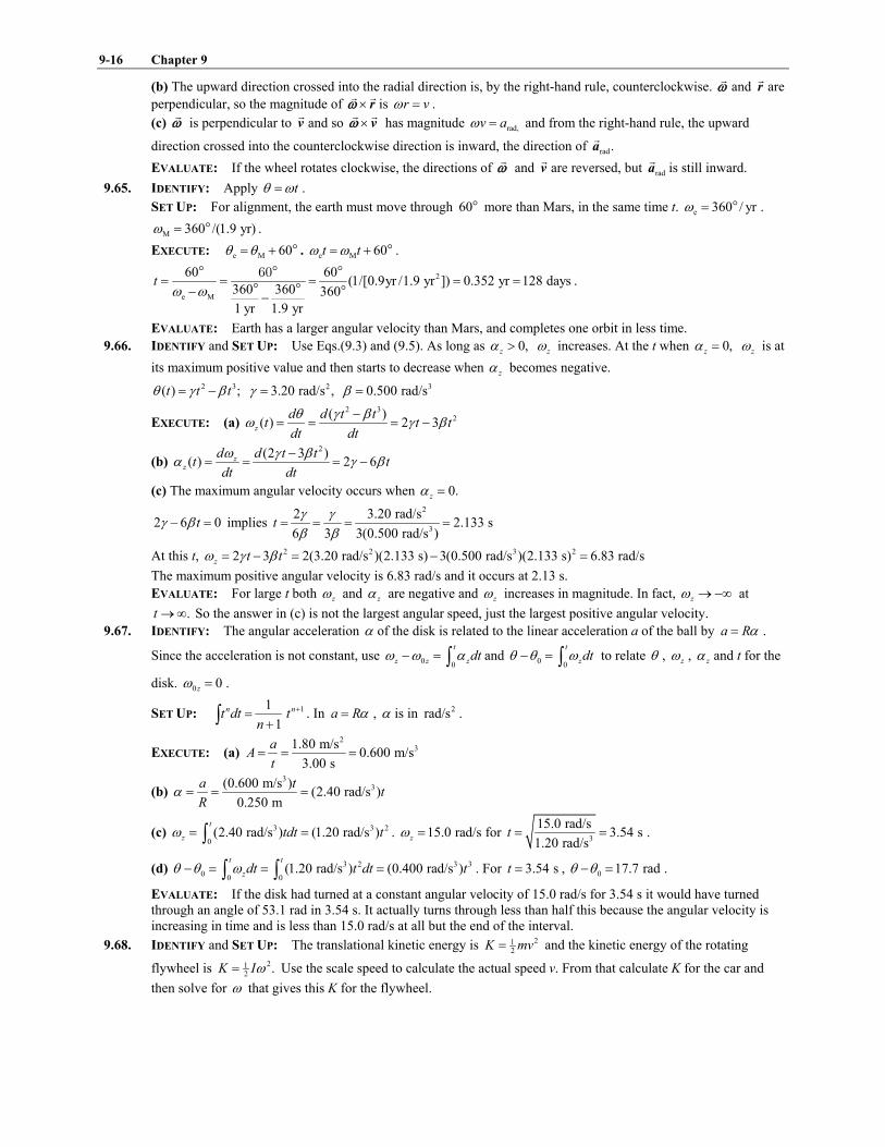
(b) The upward direction crossed into the radial direction is, by the right-hand rule, counterclockwise. !
$ and r!
are
perpendicular, so the magnitude of & r! !
$ is r v$ " .
(c) !
$ is perpendicular to v!
and so & v! !
$ has magnitude rad,v a$ " and from the right-hand rule, the upward
direction crossed into the counterclockwise direction is inward, the direction of rad.a!
EVALUATE: If the wheel rotates clockwise, the directions of !
$ and v!
are reversed, but rada!
is still inward.
9.65. IDENTIFY: Apply t! $" .
SET UP: For alignment, the earth must move through 60! more than Mars, in the same time t. e 360 / yr$ " ! .
M 360 /(1.9 yr)$ " ! .
EXECUTE: e M 60! !" ) ! . e M 60t t$ $" ) ! .
2
e M
60 60(1/[0.9yr /1.9 yr ]) 0.352 yr 128 days
360 360 360
1 yr 1.9 yr
t$ $
" " " " "% %
! "#! !
! ! !.
EVALUATE: Earth has a larger angular velocity than Mars, and completes one orbit in less time.
9.66. IDENTIFY and SET UP: Use Eqs.(9.3) and (9.5). As long as 0,z' > z$ increases. At the t when 0,z' " z$ is at
its maximum positive value and then starts to decrease when z' becomes negative.
2 3( ) ;t t t! + ," % 23.20 rad/s ,+ " 30.500 rad/s, "
EXECUTE: (a) 2 3
2( )( ) 2 3z
d d t tt t t
dt dt
! + ,$ + ,
%" " " %
(b) 2(2 3 )
( ) 2 6zz
d d t tt t
dt dt
$ + ,' + ,
%" " " %
(c) The maximum angular velocity occurs when 0.z' "
2 6 0t+ ,% " implies 2
3
2 3.20 rad/s2.133 s
6 3 3(0.500 rad/s )t
+ +, ,
" " " "
At this t, 2 2 3 22 3 2(3.20 rad/s )(2.133 s) 3(0.500 rad/s )(2.133 s)z t t$ + ," % " % " 6.83 rad/s
The maximum positive angular velocity is 6.83 rad/s and it occurs at 2.13 s.
EVALUATE: For large t both z$ and z' are negative and z$ increases in magnitude. In fact, z$ C%D at
.t CD So the answer in (c) is not the largest angular speed, just the largest positive angular velocity.
9.67. IDENTIFY: The angular acceleration ' of the disk is related to the linear acceleration a of the ball by a R'" .
Since the acceleration is not constant, use 00
t
z z zdt$ $ '% " ( and 00
t
zdt! ! $% " ( to relate ! , z$ , z' and t for the
disk. 0 0z$ " .
SET UP: 11
1
n nt dt tn
)")( . In a R'" , ' is in 2rad/s .
EXECUTE: (a) 2
31.80 m/s0.600 m/s
3.00 s
aA
t" " "
(b) 3
3(0.600 m/s )(2.40 rad/s )
0.250 m
a tt
R' " " "
(c) 3 3 2
0(2.40 rad/s ) (1.20 rad/s )
t
z tdt t$ " "( . 15.0 rad/sz$ " for 3
15.0 rad/s3.54 s
1.20 rad/st " " .
(d) 3 2 3 3
00 0
(1.20 rad/s ) (0.400 rad/s )t t
zdt t dt t! ! $% " " "( ( . For 3.54 st " , 0 17.7 rad! !% " .
EVALUATE: If the disk had turned at a constant angular velocity of 15.0 rad/s for 3.54 s it would have turned
through an angle of 53.1 rad in 3.54 s. It actually turns through less than half this because the angular velocity is
increasing in time and is less than 15.0 rad/s at all but the end of the interval.
9.68. IDENTIFY and SET UP: The translational kinetic energy is 212
K mv" and the kinetic energy of the rotating
flywheel is 212
.K I$" Use the scale speed to calculate the actual speed v. From that calculate K for the car and
then solve for $ that gives this K for the flywheel.

Rotation of Rigid Bodies 9-17
EXECUTE: (a) toy toy
scale real
v L
v L"
toy
toy scale
real
0.150 m(700 km/h) 35.0 km/h
3.0 m
Lv v
L
- . - ." " "/ 0 / 01 21 2
toy (35.0 km/h)(1000 m/1 km)(1 h/3600 s) 9.72 m/sv " "
(b) 2 21 12 2
(0.180 kg)(9.72 m/s) 8.50 JK mv" " "
(c) 212
K I$" gives that 5 2
2 2(8.50 J)652 rad/s
4.00 10 kg m
K
I$
%" " "
& <
EVALUATE: 21
2K I$" gives $ in rad/s. 652 rad/s 6200 rev/min" so the rotation rate of the flywheel is very
large.
9.69. IDENTIFY: tana r'" , 2
rada r$" . Apply the constant acceleration equations and m";F a!
!
.
SET UP: tana and rada are perpendicular components of a!
, so 2 2
rad tana a a" ) .
EXECUTE: (a) 2
2tan 3.00 m s0.050 rad s
60.0 m
a
r' " " "
(b) 2(0.05 rad s )(6.00 s) 0.300 rad s.t' " "
(c) 2 2 2
rad (0.300 rad s) (60.0 m) 5.40 m s .a r$" " "
(d) The sketch is given in Figure 9.69.
(e) 22 2 2 2 2 2
rad tan (5.40 m s ) (3.00 m s ) 6.18 m s ,a a a" ) " ) " and the magnitude of the force is
2(1240 kg)(6.18 m s ) 7.66 kN.F ma" " "
(f) rad
tan
5.40arctan arctan 60.9 .
3.00
a
a
- . - ." " 6/ 0 / 01 21 2
EVALUATE: tana is constant and rada increases as $ increases. At 0t " , a!
is parallel to v!
. As t increases,
a!
moves toward the radial direction and the angle between a!
increases toward 90! .
Figure 9.69
9.70. IDENTIFY: Apply conservation of energy to the system of drum plus falling mass, and compare the results for
earth and for Mars.
SET UP: 21
drum 2K I$" . 21
mass 2K mv" . v R$" so if drumK is the same, $ is the same and v is the same on both
planets. Therefore, massK is the same. Let 0y " at the initial height of the mass and take y) upward.
Configuration 1 is when the mass is at its initial position and 2 is when the mass has descended 5.00 m, so
1 0y " and 2y h" % , where h is the height the mass descends.
EXECUTE: (a) 1 1 2 2K U K U) " ) gives drum mass0 K K mgh" ) % . drum massK K) are the same on both planets, so
E E M Mmg h mg h" . 2
EM E 2
M
9.80 m/s(5.00 m) 13.2 m
3.71 m/s
gh h
g
- . - ." " "/ 0 / 0
1 21 2.

9-18 Chapter 9
(b) M M drum massmg h K K" ) . 21M M drum2
mv mg h K" % and
2drumM M
2 2(250.0 J)2 2(3.71 m/s )(13.2 m) 8.04 m/s
15.0 kg
Kv g h
m" % " % "
EVALUATE: We did the calculations without knowing the moment of inertia I of the drum, or the mass and radius
of the drum.
9.71. IDENTIFY and SET UP: All points on the belt move with the same speed. Since the belt doesn�t slip, the speed of
the belt is the same as the speed of a point on the rim of the shaft and on the rim of the wheel, and these speeds are
related to the angular speed of each circular object by .v r$"
EXECUTE:
Figure 9.71
(a) 1 1 1v r$"
1 (60.0 rev/s)(2 rad/1 rev) 377 rad/s$ #" "
2
1 1 1 (0.45 10 m)(377 rad/s) 1.70 m/sv r$ %" " & "
(b) 1 2v v"
1 1 2 2r r$ $"
2 1 2 1( / ) (0.45 cm/2.00 cm)(377 rad/s) 84.8 rad/sr r$ $" " "
EVALUATE: The wheel has a larger radius than the shaft so turns slower to have the same tangential speed for
points on the rim.
9.72. IDENTIFY: The speed of all points on the belt is the same, so 1 1 2 2r r$ $" applies to the two pulleys.
SET UP: The second pulley, with half the diameter of the first, must have twice the angular velocity, and this is
the angular velocity of the saw blade. rad/s 30 rev/min# " .
EXECUTE: (a) 2
rad s 0.208 m(2(3450 rev min)) 75.1 m s.
30 rev min 2v
#- .- ." "/ 0/ 01 21 2
(b)
2
2 4 2
rad
rad s 0.208 m2(3450 rev min) 5.43 10 m s ,
30 rev min 2a r
#$
- .- . - ." " " &/ 0/ 0 / 0/ 0 1 21 21 2
so the force holding sawdust on the blade would have to be about 5500 times as strong as gravity.
EVALUATE: In v r$" and 2
rada r$" , $ must be in rad/s.
9.73. IDENTIFY and SET UP: Use Eq.(9.15) to relate rada to $ and then use a constant acceleration equation to
replace .$
EXECUTE: (a) 2
rad ,a r$" 2
rad,1 1 ,a r$" 2
rad,2 2a r$"
2 2
rad rad,2 rad,1 2 1( )a a a r $ $* " % " %
One of the constant acceleration equations can be written 2 2
2 1 2 12 ( ),z z$ $ ' ! !" ) % or 2 2
2 1 2 12 ( )z z z$ $ ' ! !% " %
Thus rad 2 1 2 12 ( ) 2 ( ),z za r r' ! ! ' ! !* " % " % as was to be shown.
(b) 2 2
2rad
2 1
85.0 m/s 25.0 m/s8.00 rad/s
2 ( ) 2(0.250 m)(15.0 rad)z
a
r'
! !* %
" " "%
Then 2 2
tan (0.250 m)(8.00 rad/s ) 2.00 m/sa r'" " "
EVALUATE: 2$ is proportional to z' and 0( )! !% so rada is also proportional to these quantities. rada increases
while r stays fixed, z$ increases, and z' is positive.
IDENTIFY and SET UP: Use Eq.(9.17) to relate K and $ and then use a constant acceleration equation to replace .$
EXECUTE: (c) 212
;K I$" 212 22
,K I$" 211 12
K I$"
2 21 12 1 2 1 2 1 2 12 2
( ) (2 ( )) ( ),z zK K K I I I$ $ ' ! ! ' ! !* " % " % " % " % as was to be shown.
(d) 2
2
2 1
45.0 J 20.0 J0.208 kg m
( ) (8.00 rad/s )(15.0 rad)z
KI
' ! !* %
" " " <%
EVALUATE: z' is positive, $ increases, and K increases.

Rotation of Rigid Bodies 9-19
9.74. IDENTIFY: wood lead.I I I" ) m VA" , where A is the volume density and m AE" , where E is the area density.
SET UP: For a solid sphere, 225
I mR" . For the hollow sphere (foil), 223
I mR" . For a sphere, 343
V R#" and
24A R#" . 3
w w w w
4
3m V RA A #" " . 2
L L L L 4m A RE E #" " .
EXECUTE: 2 2 3 2 2 2 4 w
w L w L L
2 2 2 4 2 8( 4 )
5 3 5 3 3 3 5
RI m R m R R R R R R
AA # E # # E- . - ." ) " ) " )/ 0 / 01 2 1 2
.
34 2 28 (800 kg m )(0.20 m)
(0.20 m) 20 kg m 0.70 kg m3 5
I# 7 8
" ) " <? @9 :
.
EVALUATE: W 26.8 kgm " and 2
W 0.429 kg mI " < . L 10.1 kgm " and 2
L 0.268 kg mI " < . Even though the foil is
only 27% of the total mass its contribution to I is about 38% of the total.
9.75. IDENTIFY: Estimate the shape and dimensions of your body and apply the approximate expression from
Table 9.2.
SET UP: I approximate my body as a vertical cylinder with mass 80 kg, length 1.7 m, and diameter 0.30 m
(radius 0.15 m)
EXECUTE: 2 2 21 1(80 kg) (0.15 m) 0.9 kg m
2 2I mR" " " <
EVALUATE: I depends on your mass and width but not on your height.
9.76. IDENTIFY: Treat the V like two thin 0.160 kg bars, each 25 cm long.
SET UP: For a slender bar with the axis at one end, 213
I mL" .
EXECUTE: 2 2 3 21 1
2 2 (0.160 kg)(0.250 m) 6.67 10 kg m3 3
I mL %- . - ." " " & </ 0 / 01 2 1 2
EVALUATE: The value of I is independent of the angle between the two sides of the V; the angle 70.0! didn't
enter into the calculation.
9.77. IDENTIFY: 21
2K I$" . 2
rada r$" . m VA" .
SET UP: For a disk with the axis at the center, 212
I mR" . 2V t R#" , where 0.100 mt " is the thickness of the
flywheel. 37800 kg mA " is the density of the iron.
EXECUTE: (a) 90.0 rpm 9.425 rad s$ " " .6
5 2
2 2
2 2(10 0 10 J)2 252 10 kg m
(9 425 rad s)
K . I .
.$&
" " " & < .
2m V R tA A#" " . 2 41 1
2 2I mR tRA#" " . This gives 1 4(2 ) 3.68 mR I tA#" " and the diameter is 7.36 m.
(b) 2 2
rad 327m sa R$" "
EVALUATE: In 212
K I$" , $ must be in rad/s. rada is about 33g; the flywheel material must have large cohesive
strength to prevent the flywheel from flying apart.
9.78. IDENTIFY: 21
2K I$" . To have the same K for any $ the two parts must have the same I. Use Table 9.2 for I.
SET UP: For a solid sphere, 22solid solid5
I M R" . For a hollow sphere, 22hollow hollow3
I M R" .
EXECUTE: solid hollowI I" gives 2 22 2solid hollow5 3
M R M R" and 3 3hollow solid5 5
M M M" " .
EVALUATE: The hollow sphere has less mass since all its mass is distributed farther from the rotation axis.
9.79. IDENTIFY: 21
2K I$" .
2 rad
T
#$ " , where T is the period of the motion. For the earth's orbital motion it can be
treated as a point mass and 2I MR" .
SET UP: The earth's rotational period is 24 h 86,164 s" . Its orbital period is 71 yr 3.156 10 s" & .
245.97 10 kgM " & . 66.38 10 mR " & .
EXECUTE: (a) 2 2 24 6 2
29
2 2
2 2 (0.3308)(5.97 10 kg)(6.38 10 m)2.14 10 J.
(86,164 s)
IK
T
# # & &" " " &
(b)
2 2 24 11 233
7 2
1 2 2 (5.97 10 kg)(1.50 10 m)2.66 10 J.
2 (3.156 10 s)
RM
T
# # & &- . " " &/ 0 &1 2
(c) Since the Earth�s moment of inertia is less than that of a uniform sphere, more of the Earth�s mass must be
concentrated near its center.
EVALUATE: These kinetic energies are very large, because the mass of the earth is very large.

9-20 Chapter 9
9.80. IDENTIFY: Using energy considerations, the system gains as kinetic energy the lost potential energy, mgR.
SET UP: The kinetic energy is 2 21 1
2 2K I mv$" ) , with 21
2I mR" for the disk. v R$" .
EXECUTE: 2 2 21 1 1( ) ( )
2 2 2K I m R I mR$ $" ) " ) . 21
2Using and solving for ,% mR !" 2 4
3
g
R$ " and
4.
3
g
R$ "
EVALUATE: The small object has speed 2
23
v gR" . If it was not attached to the disk and was dropped from a
height h, it would attain a speed 2gR . Being attached to the disk reduces its final speed by a factor of 2
3.
9.81. IDENTIFY: Use Eq.(9.20) to calculate I. Then use 212
K I$" to calculate K.
(a) SET UP: The object is sketched in Figure 9.81.
Consider a small strip of width dy
and a distance y below the top of the
triangle.
The length of the strip is
( / ) .x y h b"
Figure 9.81
EXECUTE: The strip has area x dy and the area of the sign is 12
,bh so the mass of the strip is
212
2 2x dy yb dy Mdm M M y dy
bh h bh h
- . - .- . - ." " "/ 0 / 0/ 0 / 01 21 2 1 21 2
22 31
3 4
2( )
3
MbdI dm x y dy
h
- ." " / 0
1 2
2 23 4 2
04 40 0
2 2 1 1
3 3 6
h hhMb Mb
I dI y dy y Mbh h h
- ." " " "/ 01 2( (
(b) 2 21
62.304 kg mI Mb" " <
2.00 rev/s 4.00 rad/s$ #" " 21
2182 JK I$" "
EVALUATE: From Table (9.2), if the sign were rectangular, with length b, then 213
.I Mb" Our result is one-half
this, since mass is closer to the axis for the triangular than for the rectangular shape.
9.82. IDENTIFY: Apply conservation of energy to the system.
SET UP: For the falling mass 212
K mv" . For the wheel 212
K I$" .
EXECUTE: (a) The kinetic energy of the falling mass after 2.00 m is 3 43 4221 12 2
8.00 kg 5.00 m/s 100 J.K mv" " "
The change in its potential energy while falling is 3 43 43 428.00 kg 9.8 m/s 2.00 m 156.8 Jmgh " " . The wheel must
have the �missing� 56.8 J in the form of rotational kinetic energy. Since its outer rim is moving at the same speed
as the falling mass, 5.00 m/s , v r$" gives 5.00 m/s
13.51 rad/s0.370 m
v
r$ " " " . 21
; therefore2
K I$"
3 43 4
2
22
2 56.8 J20.622 kg m
13.51 rad s
KI
$" " " < .
(b) The wheel�s mass is 2(280 N) (9.8 m s ) 28.6 kg" . The wheel with the largest possible moment of inertia
would have all this mass concentrated in its rim. Its moment of inertia would be
3 43 422 228.6 kg 0.370 m 3.92 kg mI MR" " " < . The boss�s wheel is physically impossible.

Rotation of Rigid Bodies 9-21
EVALUATE: If the mass falls from rest in free-fall its speed after it has descended 2.00 m is
2 (2.00 m) 6.26 m/sv g" " . Its actual speed is less because some of the energy of the system is in the form of
rotational kinetic energy of the wheel.
9.83. IDENTIFY: Use conservation of energy. The stick rotates about a fixed axis so 212
.K I$" Once we have $ use
v r$" to calculate v for the end of the stick.
SET UP: The object is sketched in Figure 9.83.
Take the origin of coordinates at the lowest point reached by
the stick and take the positive y-direction to be upward.
Figure 9.83
EXECUTE: (a) Use Eq.(9.18): cmU Mgy"
2 1 cm2 cm1( )U U U Mg y y* " % " %
The center of mass of the meter stick is at its geometrical center, so
cm1 1.00 my " and cm2 0.50 my "
Then 2(0.160 kg)(9.80 m/s )(0.50 m 1.00 m) 0.784 JU* " % " %
(b) Use conservation of energy: 1 1 other 2 2K U W K U) ) " )
Gravity is the only force that does work on the meter stick, so other 0.W "
1 0.K "
Thus 2 1 2 ,K U U U" % " %* where U* was calculated in part (a).
212 22
K I$" so 2122
I U$ " %* and 2 2( ) /U I$ " %*
For stick pivoted about one end, 213
I ML" where 1.00 m,L " so
2 2 2
6( ) 6(0.784 J)5.42 rad/s
(0.160 kg)(1.00 m)
U
ML$
%*" " "
(c) (1.00 m)(5.42 rad/s) 5.42 m/sv r$" " "
(d) For a particle in free-fall, with y) upward,
0 0;yv " 0 1.00 m;y y% " % 29.80 m/s ;ya " % ?yv "
2 2
0 02 ( )y y yv v a y y" ) %
2
02 ( ) 2( 9.80 m/s )( 1.00 m) 4.43 m/sy yv a y y" % % " % % % " %
EVALUATE: The magnitude of the answer in part (c) is larger. 1,gravU is the same for the stick as for a particle
falling from a height of 1.00 m. For the stick 3 42 2 2 21 1 1 122 2 3 6
( / ) .K I ML v L Mv$" " " For the stick and for the
particle, 2K is the same but the same K gives a larger v for the end of the stick than for the particle. The reason is
that all the other points along the stick are moving slower than the end opposite the axis.
9.84. IDENTIFY: Apply conservation of energy to the system of cylinder and rope.
SET UP: Taking the zero of gravitational potential energy to be at the axle, the initial potential energy is zero (the
rope is wrapped in a circle with center on the axle).When the rope has unwound, its center of mass is a distance
R# below the axle, since the length of the rope is 2 R# and half this distance is the position of the center of the
mass. Initially, every part of the rope is moving with speed 0 ,R$ and when the rope has unwound, and the cylinder
has angular speed ,$ the speed of the rope is R$ (the upper end of the rope has the same tangential speed at the
edge of the cylinder). 2(1 2)I MR" for a uniform cylinder,

9-22 Chapter 9
EXECUTE: 1 2 2K K U" ) . 2 2 2 2
0 .4 2 4 2
M m M mR R mg R$ $ #- . - .) " ) %/ 0 / 0
1 2 1 2 Solving for$ gives
3 43 4
2
0
4
2
mg R
M m
#$ $" )
), and the speed of any part of the rope is .v R$"
EVALUATE: When 0m C , 0$ $C . When m M>> , 2
0
2 g
R
#$ $" ) and 2
0 2v v gR#" ) . This is the final
speed when an object with initial speed 0v descends a distance R# .
9.85. IDENTIFY: Apply conservation of energy to the system consisting of blocks A and B and the pulley.
SET UP: The system at points 1 and 2 of its motion is sketched in Figure 9.85.
Figure 9.85
Use the work-energy relation 1 1 other 2 2.K U W K U) ) " ) Use coordinates where y) is upward and where the origin
is at the position of block B after it has descended. The tension in the rope does positive work on block A and
negative work of the same magnitude on block B, so the net work done by the tension in the rope is zero. Both
blocks have the same speed.
EXECUTE: Gravity does work on block B and kinetic friction does work on block A. Therefore
other k .f AW W m gdF" " %
1 0K " (system is released from rest)
1 1 ;B B BU m gy m gd" " 2 2 0B BU m gy" "
2 2 21 1 12 2 2 22 2 2
.A BK m v m v I$" ) )
But (blocks) (pulley),v R$" so 2 2 /v R$ " and
2 2 2 21 1 12 2 2 22 2 2
( ) ( / ) ( / )A B A BK m m v I v R m m I R v" ) ) " ) )
Putting all this into the work-energy relation gives 2 21
k 22( / )B A A Bm gd m gd m m I R vF% " ) )
2 2
2 k( / ) 2 ( )A B B Am m I R v gd m mF) ) " %
k2 2
2 ( )
/
B A
A B
gd m mv
m m I R
F%"
) )
EVALUATE: If B Am m>> and 2/ ,I R then 2 2 ;v gd" block B falls freely. If I is very large, 2v is very small.
Must have kB Am mF> for motion, so the weight of B will be larger than the friction force on A. 2/I R has units of
mass and is in a sense the �effective mass� of the pulley.
9.86. IDENTIFY: Apply conservation of energy to the system of two blocks and the pulley.
SET UP: Let the potential energy of each block be zero at its initial position. The kinetic energy of the system is
the sum of the kinetic energies of each object. v R$" , where v is the common speed of the blocks and $ is the
angular velocity of the pulley.
EXECUTE: The amount of gravitational potential energy which has become kinetic energy is
3 43 43 424.00 kg 2.00 kg 9.80 m s 5.00 m 98.0 J.K " % " In terms of the common speed v of the blocks, the kinetic
energy of the system is
2
2
1 2
1 1( )
2 2
vK m m v I
R
- ." ) ) / 01 2
.
22 2
2
1 (0.480 kg m )4.00 kg 2 00 kg (12.4 kg).
2 (0.160 m)K v . v
- .<" ) ) "/ 0
1 2 Solving for v gives
98.0 J2.81 m s.
12.4 kgv " "

Rotation of Rigid Bodies 9-23
EVALUATE: If the pulley is massless, 212
98.0 J (4.00 kg 2.00 kg)v" ) and 5.72 m/sv " . The moment of inertia
of the pulley reduces the final speed of the blocks.
9.87. IDENTIFY and SET UP: Apply conservation of energy to the motion of the hoop. Use Eq.(9.18) to calculate grav.U
Use 212
K I$" for the kinetic energy of the hoop. Solve for .$ The center of mass of the hoop is at its geometrical
center.
Take the origin to be at the original location
of the center of the hoop, before it is rotated
to one side, as shown in Figure 9.87.
Figure 9.87
cm1 cos (1 cos )y R R R, ," % " %
cm2 0y " (at equilibrium position hoop is at original position)
EXECUTE: 1 1 other 2 2K U W K U) ) " )
other 0W " (only gravity does work)
1 0K " (released from rest), 212 22
K I$"
For a hoop, 2
cm ,I MR" so 2 2I Md MR" ) with d R" and 22 ,I MR" for an axis at the edge. Thus
2 2 2 212 2 22
(2 ) .K MR MR$ $" "
1 cm1 (1 cos ),U Mgy MgR ," " % 2 cm2 0U mgy" "
Thus 1 1 other 2 2K U W K U) ) " ) gives
2 2
2(1 cos )MgR MR, $% " and (1 cos ) /g R$ ," %
EVALUATE: If 0,, " then 2 0.$ " As , increases, 2$ increases.
9.88. IDENTIFY: 21
2K I$" , with $ in rad/s.
energyP
t"
SET UP: For a solid cylinder, 212
I MR" . 1 rev/min (2 / 60) rad/s#"
EXECUTE: (a) 3000 rev/min 314 rad/s$ " " . 2 212(1000 kg)(0.900 m) 405 kg mI " " <
2 2 712(405 kg m )(314 rad/s) 2.00 10 JK " < " & .
(b) 7
3
4
2.00 10 J1.08 10 s 17.9 min
1.86 10 W
Kt
P
&" " " & "
&.
EVALUATE: In 212
K I$" , we must use $ in rad/s.
9.89. IDENTIFY: 1 2I I I" ) . Apply conservation of energy to the system. The calculation is similar to Example 9.9.
SET UP: 1
v
R$ " for part (b) and
2
v
R$ " for part (c).
EXECUTE: (a) 2 2 2 2 2 2
1 1 2 2
1 1 1((0.80 kg)(2.50 10 m) (1.60 kg)(5 00 10 m) )
2 2 2I M R M R .% %" ) " & ) &
3 22.25 10 kg m .I %" & <
(b) The method of Example 9.9 yields 2
1
2
1 ( )
ghv
I mR"
).
2
3 2 2
2(9.80 m s )(2.00 m)3.40 m s.
(1 ((2.25 10 kg m ) (1.50 kg)(0.025 m) ))v %" "
) & <
The same calculation, with 2R instead of 1R gives 4.95 m s.v "
EVALUATE: The final speed of the block is greater when the string is wrapped around the larger disk. v R$" , so
when 2R R" the factor that relates v to $ is larger. For 2R R" a larger fraction of the total kinetic energy resides

9-24 Chapter 9
with the block. The total kinetic energy is the same in both cases (equal to mgh), so when 2R R" the kinetic energy
and speed of the block are greater.
9.90. IDENTIFY: Apply conservation of energy to the motion of the mass after it hits the ground.
SET UP: From Example 9.9, the speed of the mass just before it hits the ground is 2
1 / 2
ghv
M m"
).
EXECUTE: (a) In the case that no energy is lost, the rebound height hG is related to the speed v by 2
2
vh
gG " , and
with the form for v given in Example 9.9, .1 2
hhM m
G ")
(b) Considering the system as a whole, some of the initial potential energy of the mass went into the kinetic energy
of the cylinder. Considering the mass alone, the tension in the string did work on the mass, so its total energy is not
conserved.
EVALUATE: If m M>> , h hG " and the mass does rebound to its initial height.
9.91. IDENTIFY: Apply conservation of energy to relate the height of the mass to the kinetic energy of the cylinder.
SET UP: First use (cylinder) 250 JK " to find $ for the cylinder and v for the mass.
EXECUTE: 2 21 1
2 2(10.0 kg)(0.150 m) 0.1125 kg mI MRH" " " <
212
K I$" so 2 / 66.67 rad/sK I$ " "
10.0 m/sv R$" "
SET UP: Use conservation of energy 1 1 2 2K U K U) " ) to solve for the distance the mass descends. Take 0y "
at lowest point of the mass, so 2 0y " and 1 ,y h" the distance the mass descends.
EXECUTE: 1 2 0K U" " so 1 2.U K"
2 21 12 2
,mgh mv I$" ) where 12.0 kgm "
For the cylinder, 212
I MR" and / ,v R$ " so 2 21 12 4
.I Mv$ "
2 21 12 4
mgh mv Mv" )
2
1 7.23 m2 2
v Mh
g m
- ." ) "/ 01 2
EVALUATE: For the cylinder 3 42 2 2 21 1 1 1cyl 2 2 2 4
( / ) .K I MR v R Mv$" " "
21mass 2
,K mv" so mass cyl(2 / ) [2(12.0 kg)/10.0 kg](250 J) 600 J.K m M K" " " The mass has 600 J of kinetic energy
when the cylinder has 250 J of kinetic energy and at this point the system has total energy 850 J since 2 0.U "
Initially the total energy of the system is 1 1 850 J,U mgy mgh" " " so the total energy is shown to be conserved.
9.92. IDENTIFY: Energy conservation: Loss of U of box equals gain in K of system. Both the cylinder and pulley have
kinetic energy of the form 212
K I$" . 2 2 2
box box box pulley pulley cylinder cylinder
1 1 1
2 2 2m gh m v I I$ $" ) ) .
SET UP: Box Boxpulley cylinder
p cylinder
and v v
r r$ $" " .
EXECUTE:
2 2
2 2 2 BB B B P p C C
p C
1 1 1 1 1
2 2 2 2 2
Bv vm gh m v m r m r
r r
- . - .- . - ." ) )/ 0 / 0/ 0 / 0/ 01 2 1 2 1 21 2. 2 2 2
B B B P B C B
1 1 1
2 4 4m gh m v m v m v" ) ) and
2
BB 1 1 1 1
B p C2 4 4 4
(3.00 kg)(9.80 m s )(1.50 m)3.68 m s
1.50 kg (7.00 kg)
m ghv
m m m" " "
) ) ).
EVALUATE: If the box was disconnected from the rope and dropped from rest, after falling 1.50 m its speed
would be 2 (1.50 m) 5.42 m/sv g" " . Since in the problem some of the energy of the system goes into kinetic
energy of the cylinder and of the pulley, the final speed of the box is less than this.
9.93. IDENTIFY: disk holeI I I" % , where holeI is I for the piece punched from the disk. Apply the parallel-axis theorem to
calculate the required moments of inertia.
SET UP: For a uniform disk, 212
I MR" .

Rotation of Rigid Bodies 9-25
EXECUTE: (a) The initial moment of inertia is 210 2
.I MR" The piece punched has a mass of 16
M and a moment
of inertia with respect to the axis of the original disk of
2 2
21 9.
16 2 4 2 512
M R RMR
7 8- . - .) "? @/ 0 / 01 2 1 2? @9 :
The moment of inertia of the remaining piece is then 2 2 21 9 247.
2 512 512I MR MR MR" % "
(b)2 2 2 23831 1
2 2 512 ( / 2) ( /16)( / 4) .I MR M R M R MR" ) % "
EVALUATE: For a solid disk and an axis at a distance / 2R from the disk's center, the parallel-axis theorem gives 2 2 23 3841
2 4 512I MR MR MR" " " . For both choices of axes the presence of the hole reduces I, but the effect of the hole
is greater in part (a), when it is farther from the axis.
9.94. IDENTIFY: In part (a) use the parallel-axis theorem to relate the moment of inertia cmI for an axis through the
center of the sphere to PI , the moment of inertia for an axis at the pivot.
SET UP: I for a uniform solid sphere and the axis through its center is 22
5.MR I for a slender rod and an axis at
one end is 213mL , where m is the mass of the rod and L is its length.
EXECUTE: (a) From the parallel-axis theorem, the moment of inertia is 2 2(2 5) ,PI MR ML" ) and
2
2
21 .
5
PI R
ML L
- .- .- ." )/ 0/ 0/ 0/ 01 21 21 2 If (0.05) ,R L" the difference is 2(2 5)(0.05) 0.001 0.1%." "
(b) 2
rod rod ( ) ( 3 ),I ML m M" which is 0.33% when rod (0.01) .m M"
EVALUATE: In both these cases the correction to 2I ML" is very small.
9.95. IDENTIFY: Follow the instructions in the problem to derive the perpendicular-axis theorem. Then apply that
result in part (b).
SET UP: 2
i i
i
I m r"; . The moment of inertia for the washer and an axis perpendicular to the plane of the washer
at its center is 2 211 22
( )M R R) . In part (b), I for an axis perpendicular to the plane of the square at its center is
2 2 21 112 6
( )M L L ML) " .
EXECUTE: (a) With respect to O, 2 2 2 ,i i ir x y" ) and so
2 2 2 2 2( ) .O i i i i i i i i i x y
i i i i
I m r m x y m x m y I I" " ) " ) " ); ; ; ;
(b) Two perpendicular axes, both perpendicular to the washer�s axis, will have the same moment of inertia about
those axes, and the perpendicular-axis theorem predicts that they will sum to the moment of inertia about the
washer axis, which is 2 211 22
( ),I M R R" ) and so xI yI" 2 211 24
( ).M R R" )
(c) 21
0 6.I mL" Since 1
0 12, and , both and must be x y x y x yI I I I I I I" ) " 2.mL
EVALUATE: The result in part (c) says that I is the same for an axis that bisects opposite sides of the square as for
an axis along the diagonal of the square, even though the distribution of mass relative to the two axes is quite
different in these two cases.
9.96. IDENTIFY: Apply the parallel-axis theorem to each side of the square.
SET UP: Each side has length a and mass / 4,M and the moment of inertia of each side about an axis
perpendicular to the side and through its center is 2 21 1 112 4 48
Ma Ma" .
EXECUTE: The moment of inertia of each side about the axis through the center of the square is, from the
perpendicular axis theorem, 3 422 2
48 4 2 12Ma a MaM) " . The total moment of inertia is the sum of the contributions
from the four sides, or 2 2
4 .12 3
Ma Ma& "
EVALUATE: If all the mass of a side were at its center, a distance / 2a from the axis, we would have 2
214
4 2 4
M aI Ma
- .- ." "/ 0/ 01 21 2
. If all the mass was divided equally among the four corners of the square, a distance
/ 2a from the axis, we would have
2
214
4 22
M aI Ma
- .- ." "/ 0/ 01 21 2
. The actual I is between these two values.

9-26 Chapter 9
9.97. IDENTIFY: Use Eq.(9.20) to calculate I.
(a) SET UP: Let L be the length of the cylinder. Divide the cylinder into thin cylindrical shells of inner radius r
and outer radius .r dr) An end view is shown in Figure 9.97.
rA '"
The mass of the thin cylindrical shell is 2(2 ) 2 dm dV r dr L Lr drA A # #'" " "
Figure 9.97
EXECUTE: 3 42 4 5 51 2
5 50 2 2
R
I r dm L r dr L R LR#' #' #'" " " "( (
Relate M to :' 3 42 3 31 2
3 302 2 ,
R
M dm L r dr L R LR#' #' #'" " " "( ( so 3 3 / 2.LR M#' "
Using this in the above result for I gives 2 2325 5(3 / 2) .I M R MR" "
(b) EVALUATE: For a cylinder of uniform density 212
.I MR" The answer in (a) is larger than this. Since the
density increases with distance from the axis the cylinder in (a) has more mass farther from the axis than for a
cylinder of uniform density.
9.98. IDENTIFY: Write K in terms of the period T and take derivatives of both sides of this equation to relate /dK dt to
/dT dt .
SET UP: 2
T
#$ " and 21
2K I$" . The speed of light is 83.00 10 m/sc " & .
EXECUTE: (a) 2
2
2 IK
T
#" .
2
3
4dK I dT
dt T dt
#" % . The rate of energy loss is
2
3
4 I dT
T dt
#. Solving for the moment of
inertia in terms of the power ,I P
3 31 338 2
2 13
1 (5 10 W)(0.0331 s) 1 s 1.09 10 kg m
4 4 4.22 10 s
PTI
dT dt# # %
&" " " & <
&
(b) 38 2
3
30
5 5(1.08 10 kg m )9.9 10 m, about 10 km.
2 2(1.4)(1.99 10 kg)
IR
M
& <" " " &
&
(c) 3
6 32 2 (9.9 10 m)1.9 10 m s 6.3 10 .
(0.0331 s)
Rv c
T
# # %&" " " & " &
(d) 17 3
36.9 10 kg m ,
(4 3)
M M
V RA
#" " " & which is much higher than the density of ordinary rock by 14 orders of
magnitude, and is comparable to nuclear mass densities.
EVALUATE: I is huge because M is huge. A small rate of change in the period corresponds to a large release of
energy.
9.99. IDENTIFY: In part (a), do the calculations as specified in the hint. In part (b) calculate the mass of each shell of
inner radius 1R and outer radius 2R and sum to get the total mass. In part (c) use the expression in part (a) to
calculate I for each shell and sum to get the total I.
SET UP: m VA" . For a solid sphere, 343
V R#" .
EXECUTE: (a) Following the hint, the moment of inertia of a uniform sphere in terms of the mass density is 2 582
5 15,I MR R#A" " and so the difference in the moments of inertia of two spheres with the same density A but
different radii 5 5
2 1 2 1 and is (8 15)( ).R R I R RA #" %
(b) A rather tedious calculation, summing the product of the densities times the difference in the cubes of the radii
that bound the regions and multiplying by 24 4 3, gives 5.97 10 kg.M# " &
(c) A similar calculation, summing the product of the densities times the difference in the fifth powers of the radii
that bound the regions and multiplying by 22 2 28 15, gives 8.02 10 kg m 0.334 .I MR# " & < "
EVALUATE: The calculated value of 20.334I MR" agrees closely with the measured value of 20.3308MR . This
simple model is fairly accurate.

Rotation of Rigid Bodies 9-27
9.100. IDENTIFY: Apply Eq.(9.20)
SET UP: Let z be the coordinate along the vertical axis. ( )zR
r zh
" . 2 2
2
R zdm
h#A" and
44
42
RdI z dz
h
#A" .
EXECUTE: 4 4
4 5 4
4 00
1
2 10 10
h h R R
I dI z dz z R h .h h
#A #A#A7 8" " " "9 :( ( The volume of a right circular cone is
2 21 1
3 3, the mass is and soV R h R h# #A"
22 23 3
.10 3 10
R hI R MR
#A- ." "/ 0
1 2
EVALUATE: For a uniform cylinder of radius R and for an axis through its center, 212
I MR" . I for the cone is
less, as expected, since the cone is constructed from a series of parallel discs whose radii decrease from R to zero
along the vertical axis of the cone.
9.101. IDENTIFY: Follow the steps outlined in the problem.
SET UP: /z d dt$ !" . 2 2/z zd dt' $" .
EXECUTE: (a) 0 ds r d r d d! ! ,! !" " ) so 2
0( )2
s r,! ! !" ) . ! must be in radians.
(b) Setting 2
0 2s vt r
,! !" " ) gives a quadratic in ! . The positive solution is
2
0 0
1) 2(t r vt r! ,
,7 8" ) %9 :
.
(The negative solution would be going backwards, to values of r smaller than 0r .)
(c) Differentiating, 2
0
( ) ,2
z
d vt
dt r vt
!$
," "
)
3 42
3 22
0
.2
zz
d v
dt r vt
$ ,'
," " %
) The angular acceleration z' is not
constant.
(d) 0 25.0 mm.r " ! must be measured in radians, so 3 43 41.55 m rev 1 rev 2 rad 0.247 m rad. , F # F" " Using
( )t! from part (b), the total angle turned in 74.0 min 4440 s" is
3 43 43 4 3 427 3 3
7
12 2.47 10 m/rad 1.25 m/s 4440 s 25.0 10 m 25.0 10 m
2.47 10 m/rad! % % %
%
- ." & ) & % &/ 0& 1 2
5= 1.337 10 rad! & , which is 42.13 10 rev& .
(e) The graphs are sketched in Figure 9.101.
EVALUATE: z$ must decrease as r increases, to keep v r$" constant. For z$ to decrease in time, z' must be
negative.
Figure 9.101

10-1
DYNAMICS OF ROTATIONAL MOTION
10.1. IDENTIFY: Use Eq.(10.2) to calculate the magnitude of the torque and use the right-hand rule illustrated in
Fig.(10.4) to calculate the torque direction.
(a) SET UP: Consider Figure 10.1a.
EXECUTE: Fl! "
sin (4.00 m)sin90l r #" " $
4.00 ml "
(10.0 N)(4.00 m) 40.0 N m! " " %
Figure 10.1a
This force tends to produce a counterclockwise rotation about the axis; by the right-hand rule the vector !!
is
directed out of the plane of the figure.
(b) SET UP: Consider Figure 10.1b.
EXECUTE: Fl! "
sin (4.00 m)sin120l r #" " $
3.464 ml "
(10.0 N)(3.464 m) 34.6 N m! " " %
Figure 10.1b
This force tends to produce a counterclockwise rotation about the axis; by the right-hand rule the vector !!
is
directed out of the plane of the figure.
(c) SET UP: Consider Figure 10.1c.
EXECUTE: Fl! "
sin (4.00 m)sin30l r #" " $
2.00 ml "
(10.0 N)(2.00 m) 20.0 N m! " " %
Figure 10.1c
This force tends to produce a counterclockwise rotation about the axis; by the right-hand rule the vector !!
is
directed out of the plane of the figure.
(d) SET UP: Consider Figure 10.1d.
EXECUTE: Fl! "
sin (2.00 m)sin 60 1.732 ml r #" " $ "
(10.0 N)(1.732 m) 17.3 N m! " " %
Figure 10.1d
This force tends to produce a clockwise rotation about the axis; by the right-hand rule the vector !!
is directed into
the plane of the figure.
(e) SET UP: Consider Figure 10.1e.
EXECUTE: Fl! "
0r " so 0l " and 0! "
Figure 10.1e
10

10-2 Chapter 10
(f) SET UP: Consider Figure 10.1f.
EXECUTE: Fl! "
sin ,l r #" 180 ,# " $
so 0l " and 0! "
Figure 10.1f
EVALUATE: The torque is zero in parts (e) and (f) because the moment arm is zero; the line of action of the force
passes through the axis.
10.2. IDENTIFY: Fl! " with sinl r #" . Add the two torques to calculate the net torque.
SET UP: Let counterclockwise torques be positive.
EXECUTE: 1 1 1 (8.00 N)(5.00 m) 40.0 N mFl! " & " & " & % . 2 2 2 (12.0 N)(2.00 m)sin30.0 12.0 N mF l! " ' " " ' %! .
1 2 28.0 N m! ! !" ' " & %( . The net torque is 28.0 N m% , clockwise.
EVALUATE: Even though 1 2F F) , the magnitude of 1! is greater than the magnitude of 2 ,! because 1F has a
larger moment arm.
10.3. IDENTIFY and SET UP: Use Eq.(10.2) to calculate the magnitude of each torque and use the right-hand rule
(Fig.10.4) to determine the direction. Consider Figure 10.3
Figure 10.3
Let counterclockwise be the positive sense of rotation.
EXECUTE: 2 2
1 2 3 (0.090 m) (0.090 m) 0.1273 mr r r" " " ' "
1 1 1Fl! " &
1 1 1sin (0.1273 m)sin135 0.0900 ml r #" " $ "
1 (18.0 N)(0.0900 m) 1.62 N m! " & " & %
1!!
is directed into paper
2 2 2F l! " '
2 2 2sin (0.1273 m)sin135 0.0900 ml r #" " $ "
2 (26.0 N)(0.0900 m) 2.34 N m! " ' " ' %
2!!
is directed out of paper
3 3 3F l! " '
3 3 3sin (0.1273 m)sin90 0.1273 ml r #" " $ "
3 (14.0 N)(0.1273 m) 1.78 N m! " ' " ' %
3!!
is directed out of paper
1 2 3 1.62 N m 2.34 N m 1.78 N m 2.50 N m! ! ! !" ' ' " & % ' % ' % " %(
EVALUATE: The net torque is positive, which means it tends to produce a counterclockwise rotation; the vector
torque is directed out of the plane of the paper. In summing the torques it is important to include ' or & signs to
show direction.
10.4. IDENTIFY: Use sinFl rF! #" " to calculate the magnitude of each torque and use the right-hand rule to
determine the direction of each torque. Add the torques to find the net torque.

Dynamics of Rotational Motion 10-3
SET UP: Let counterclockwise torques be positive. For the 11.9 N force ( 1F ), 0r " . For the 14.6 N force ( 2F ),
0.350 mr " and 40.0# " ! . For the 8.50 N force ( 3F ), 0.350 mr " and 90.0# " !
EXECUTE: 1 0! " . 2 (14.6 N)(0.350 m)sin 40.0 3.285 N m! " & " & %! .
3 (8.50 N)(0.350 m)sin90.0 2.975 N m! " ' " ' %! . 3.285 N m 2.975 N m 0.31 N m! " & % ' % " & %( .The net torque
is 0.31 N m% and is clockwise.
EVALUATE: If we treat the torques as vectors, 2!!
is into the page and 3!!
is out of the page.
10.5. IDENTIFY and SET UP: Calculate the torque using Eq.(10.3) and also determine the direction of the torque using
the right-hand rule.
(a) � �( 0.450 m) (0.150 m) ;" & 'r i j!
� �( 5.00 N) (4.00 N) ." & 'F i j!
The sketch is given in Figure 10.5.
Figure 10.5
EXECUTE: (b) When the fingers of your right hand curl from the direction of r!
into the direction of F!
(through
the smaller of the two angles, angle )# your thumb points into the page (the direction of ,!!
the -direction).z&
(c) � � � �( 0.450 m) +(0.150 m) ( 5.00 N) (4.00 N)! * + * +" , " & , & '- . - .r F i j i j!
!!
� � � � � � � �(2.25 N m) (1.80 N m) (0.750 N m) (0.600 N m)! " ' % , & % , & % , ' % ,i i i j j i j j!
� � � �, " , " 0i i j j
� � �,,i j = k � � �, " &j i k
Thus � � �(1.80 N m) (0.750 N m)( ) ( 1.05 N m) .! " & % & % & " & %k k k!
EVALUATE: The calculation gives that !!
is in the -direction.z& This agrees with what we got from the right-
hand rule.
10.6. IDENTIFY: Use sinFl rF! #" " for the magnitude of the torque and the right-hand rule for the direction.
SET UP: In part (a), 0.250 mr " and 37# " !
EXECUTE: (a) (17.0 N)(0.250 m)sin37 2.56 N m! " " %! . The torque is counterclockwise.
(b) The torque is maximum when 90# " ! and the force is perpendicular to the wrench. This maximum torque is
(17.0 N)(0.250 m) 4.25 N m" % .
EVALUATE: If the force is directed along the handle then the torque is zero. The torque increases as the angle
between the force and the handle increases.
10.7. IDENTIFY: Apply z zI! /"( .
SET UP: 0 0z0 " . 2 rad/rev
(400 rev/min) 41.9 rad/s60 s/min
z
10 2 3" "4 5
6 7
EXECUTE: 8 920 41.9 rad/s2.50 kg m 13.1 N m.
8.00 s
z zz zI! I
t
0 0!
&" " " % " %
EVALUATE: In z zI! /" , z/ must be in 2rad/s .
10.8. IDENTIFY: Use a constant acceleration equation to calculate z/ and then apply z zI! /"( .
SET UP: 2 22
3 2 , where 8.40 kg, 2.00 kgI MR mR M m" ' " " , so 20.600 kg mI " % .
0 75.0 rpm 7.854 rad s; 50.0 rpm 5.236 rad s; 30.0 sz z" " t" " " " " .
EXECUTE: z
2
0 gives 0.08726 rad sz z z" " ! t !" ' " & . 0.0524 N mz z# I!" " & %
EVALUATE: The torque is negative because its direction is opposite to the direction of rotation, which must be
the case for the speed to decrease.
10.9. IDENTIFY: Use z zI! /"( to calculate / . Use a constant angular acceleration kinematic equation to relate z/ ,
z0 and t.
SET UP: For a solid uniform sphere and an axis through its center, 22
5I MR" . Let the direction the sphere is
spinning be the positive sense of rotation. The moment arm for the friction force is 0.0150 ml " and the torque due
to this force is negative.

10-4 Chapter 10
EXECUTE: (a) 2
225
(0.0200 N)(0.0150 m)14.8 rad/s
(0.225 kg)(0.0150 m)
zz
I
!/
&" " " &
(b) 0 22.5 rad/sz z0 0& " & . 0z z zt0 0 /" ' gives 0
2
22.5 rad/s1.52 s
14.8 rad/s
z z
z
t0 0/& &
" " "&
.
EVALUATE: The fact that z/ is negative means its direction is opposite to the direction of spin. The negative
z/ causes z0 to decrease.
10.10. IDENTIFY: Apply z zI! /"( to the wheel. The acceleration a of a point on the cord and the angular acceleration
/ of the wheel are related by a R/" .
SET UP: Let the direction of rotation of the wheel be positive. The wheel has the shape of a disk and 21
2I MR" .
The free-body diagram for the wheel is sketched in Figure 10.10a for a horizontal pull and in Figure 10.10b for a
vertical pull. P is the pull on the cord and F is the force exerted on the wheel by the axle.
EXECUTE: (a) 2
212
(40.0 N)(0.250 m)34.8 rad/s
(9.20 kg)(0.250 m)
zz
I
!/ " " " . 2 2(0.250 m)(34.8 rad/s ) 8.70 m/sa R/" " " .
(b) xF P" & , yF Mg" & . 2 2 2 2 2( ) (40.0 N) ([9.20 kg][9.80 m/s ]) 98.6 NF P Mg" ' " ' " .
2(9.20 kg)(9.80 m/s )tan
40.0 N
y
x
F Mg
F P# " " " and 66.1# " ! . The force exerted by the axle has magnitude 98.6 N and
is directed at 66.1! above the horizontal, away from the direction of the pull on the cord.
(c) The pull exerts the same torque as in part (a), so the answers to part (a) don�t change. In part (b),
F P Mg' " and 2(9.20 kg)(9.80 m/s ) 40.0 N 50.2 NF Mg P" & " & " . The force exerted by the axle has
magnitude 50.2 N and is upward.
EVALUATE: The weight of the wheel and the force exerted by the axle produce no torque because they act at the
axle.
Figure 10.10
10.11. IDENTIFY: Use a constant angular acceleration equation to calculate z/ and then apply z zI! /"( to the motion
of the cylinder. k kf n:" .
SET UP: 8 98 922 21 1
2 28.25 kg 0.0750 m 0.02320 kg mI mR" " " % . Let the direction the cylinder is rotating be
positive. 0 0220 rpm 23.04 rad/s; 0; 5.25 rev 33.0 radz z" " $ $" " " & " " .
EXECUTE: 8 92 2
0 02z z z" " ! $ $" ' & gives 28.046 rad/sz! " & . k kz f# # f R % nR( " " & " & . Then z zI! /"( gives
k z% nR I!& " and k
7.47 NzI!n
% R" " .
EVALUATE: The friction torque is directed opposite to the direction of rotation and therefore produces an angular
acceleration that slows the rotation.
10.12. IDENTIFY: Apply m"(F a!
!
to the stone and z zI! /"( to the pulley. Use a constant acceleration equation to
find a for the stone.
SET UP: For the motion of the stone take y' to be downward. The pulley has 21
2I MR" . a R/" .

Dynamics of Rotational Motion 10-5
EXECUTE: (a) 210 0 2y yy y v t a t& " ' gives 8 921
212.6 m 3.00 sya" and 22.80 m sya " . Then y yF ma"( applied
to the stone gives mg T ma& " . z zI! /"( applied to the pulley gives 8 92 21 1
2 2/TR MR MR a R/" " . 1
2T Ma" .
Combining these two equations to eliminate T gives
2
2 2
10.0 kg 2.80 m/s2.00 kg
2 2 9.80 m/s 2.80 m/s
M aM
g a
2 32 3 2 3" " "4 54 5 4 5& &6 76 7 6 7.
(b) 8 98 921 110.0 kg 2.80 m/s 14.0 N
2 2T Ma" " "
EVALUATE: The tension in the wire is less than the weight 19.6 Nmg " of the stone, because the stone has a
downward acceleration.
10.13. IDENTIFY: Use the kinematic information to solve for the angular acceleration of the grindstone. Assume that the
grindstone is rotating counterclockwise and let that be the positive sense of rotation. Then apply Eq.(10.7) to
calculate the friction force and use k kf n:" to calculate k .:
SET UP: 0 850 rev/min(2 rad/1 rev)(1 min/60 s) 89.0 rad/sz0 1" "
7.50 s;t " 0z0 " (comes to rest); ?z/ "
EXECUTE: 0z z zt0 0 /" '
20 89.0 rad/s11.9 rad/s
7.50 sz/
&" " &
SET UP: Apply z zI! /"( to the grindstone. The free-body diagram is given in Figure 10.13.
Figure 10.13
The normal force has zero moment arm for rotation about an axis at the center of the grindstone, and therefore zero
torque. The only torque on the grindstone is that due to the friction force kf exerted by the ax; for this force the
moment arm is l R" and the torque is negative.
EXECUTE: k kz f R nR! :" & " &(
21
2I MR" (solid disk, axis through center)
Thus z zI! /"( gives 8 921k 2 znR MR: /& "
2
k
(50.0 kg)(0.260 m)( 11.9 rad/s )0.483
2 2(160 N)
zMR
n
/:
&" & " & "
EVALUATE: The friction torque is clockwise and slows down the counterclockwise rotation of the grindstone.
10.14. IDENTIFY: Apply y yF ma"( to the bucket, with y' downward. Apply z zI! /"( to the cylinder, with the
direction the cylinder rotates positive.
SET UP: The free-body diagram for the bucket is given in Fig.10.14a and the free-body diagram for the cylinder
is given in Fig.10.14b. 21
2I MR" . (bucket) (cylinder)a R/"
EXECUTE: (a) For the bucket, mg T ma& " . For the cylinder, z zI! /"( gives 21
2TR MR /" . /a R/ " then
gives 1
2T Ma" . Combining these two equations gives 1
2mg Ma ma& " and
2 215.0 kg(9.80 m/s ) 7.00 m/s
/ 2 15.0 kg 6.0 kg
mga
m M
2 3" " "4 5' '6 7
.
2 2( ) (15.0 kg)(9.80 m/s 7.00 m/s ) 42.0 NT m g a" & " & " .
(b) 2 2
0 02 ( )y y yv v a y y" ' & gives 22(7.00 m/s )(10.0 m) 11.8 m/syv " " .
(c) 27.00 m/sya " , 0 0yv " , 0 10.0 my y& " . 210 0 2y yy y v t t/& " ' gives 0
2
2( ) 2(10.0 m)1.69 s
7.00 m/sy
y yt
a
&" " "

10-6 Chapter 10
(d) y yF ma"( applied to the cylinder gives 0n T Mg& & " and
242.0 N (12.0 kg)(9.80 m/s ) 160 Nn T mg" ' " ' " .
EVALUATE: The tension in the rope is less than the weight of the bucket, because the bucket has a downward
acceleration. If the rope were cut, so the bucket would be in free-fall, the bucket would strike the water in
2
2(10.0 m)1.43 s
9.80 m/st " " and would have a final speed of 14.0 m/s. The presence of the cylinder slows the fall of
the bucket.
Figure 10.14
10.15. IDENTIFY: Apply m"(F a!
!
to each book and apply z zI! /"( to the pulley. Use a constant acceleration
equation to find the common acceleration of the books.
SET UP: 1 2.00 kgm " , 2 3.00 kgm " . Let 1T be the tension in the part of the cord attached to 1m and 2T be the
tension in the part of the cord attached to 2m . Let the -directionx' be in the direction of the acceleration of each
book. a R/" .
EXECUTE: (a) 210 0 2x xx x v t a t& " ' gives 20
2 2
2( ) 2(1.20 m)3.75 m/s
(0.800 s)x
x xa
t
&" " " . 2
1 3.75 m/sa " so
1 1 1 7.50 NT m a" " and 8 92 2 1 18.2 NT m g a" & " .
(b) The torque on the pulley is 8 92 1 0.803 N m,T T R& " % and the angular acceleration is
2 2
1 50 rad/s , so 0.016 kg m .a R I/ ! /" " " " %
EVALUATE: The tensions in the two parts of the cord must be different, so there will be a net torque on the
pulley.
10.16. IDENTIFY: Apply m(F = a!
!
to each box and z zI! /"( to the pulley. The magnitude a of the acceleration of
each box is related to the magnitude of the angular acceleration / of the pulley by a R/" .
SET UP: The free-body diagrams for each object are shown in Figure 10.16a-c. For the pulley, 0.250 mR " and 21
2I MR" . 1T and 2T are the tensions in the wire on either side of the pulley. 1 12.0 kgm " , 2 5.00 kgm " and
2.00 kgM " . F!
is the force that the axle exerts on the pulley. For the pulley, let clockwise rotation be positive.
EXECUTE: (a) x xF ma"( for the 12.0 kg box gives 1 1T m a" . y yF ma"( for the 5.00 kg weight gives
2 2 2m g T m a& " . z zI! /"( for the pulley gives 212 1 2
( ) ( )T T R MR /& " . a R/" and 12 1 2
T T Ma& " . Adding these
three equations gives 12 1 2 2
( )m g m m M a" ' ' and
2 22
11 2 2
5.00 kg(9.80 m/s ) 2.72 m/s
12.0 kg 5.00 kg 1.00 kg
ma g
m m M
2 3 2 3" " "4 5 4 5' ' ' '6 76 7
. Then
2
1 1 (12.0 kg)(2.72 m/s ) 32.6 NT m a" " " . 2 2 2m g T m a& " gives
2 2
2 2 ( ) (5.00 kg)(9.80 m/s 2.72 m/s ) 35.4 NT m g a" & " & " . The tension to the left of the pulley is 32.6 N and
below the pulley it is 35.4 N.
(b) 22.72 m/sa "
(c) For the pulley, x xF ma"( gives 1 32.6 NxF T" " and y yF ma"( gives
2
2 (2.00 kg)(9.80 m/s ) 35.4 N 55.0 NyF Mg T" ' " ' " .

Dynamics of Rotational Motion 10-7
EVALUATE: The equation 12 1 2 2
( )m g m m M a" ' ' says that the external force 2m g must accelerate all three
objects.
Figure 10.16
10.17. IDENTIFY: Apply z zI! /"( to the post and m(F = a!
!
to the hanging mass. The acceleration a!
of the mass has
the same magnitude as the tangential acceleration tana r/" of the point on the post where the string is attached;
1.75 m 0.500 m 1.25 mr " & " .
SET UP: The free-body diagrams for the post and mass are given in Figures 10.17a and b. The post has 21
3I ML" , with 15.0 kgM " and 1.75 mL " .
EXECUTE: (a) z zI! /"( for the post gives 8 921
3Tr ML /" . a r/" so
a
r/ " and
2
23
MLT a
r
2 3" 4 56 7
. y yF ma"( for
the mass gives mg T ma& " . These two equations give 2 2( /[3 ])mg m ML r a" ' and
2 2
2 2 2 2
5.00 kg(9.80 m/s ) 3.31 m/s
/[3 ] 5.00 kg [15.0 kg][1.75 m] /3[1.25 m]
ma g
m ML r
2 32 3" " "4 54 5' '6 7 6 7
.
223.31 m/s
2.65 rad/s1.25 m
a
r/ " " " .
(b) No. As the post rotates and the point where the string is attached moves in an arc of a circle, the string is no
longer perpendicular to the post. The torque due to this tension changes and the acceleration due to this torque is
not constant.
(c) From part (a), 23.31 m/sa " . The acceleration of the mass is not constant. It changes as / for the post changes.
EVALUATE: At the instant the cable breaks the tension in the string is less than the weight of the mass because
the mass accelerates downward and there is a net downward force on it.
Figure 10.17
10.18. IDENTIFY: Apply z zI! /"( to the rod.
SET UP: For the rod and axis at one end, 21
3I Ml" .
EXECUTE: 21
3
3.
Fl F
I Ml Ml
!/ " " "
EVALUATE: Note that / decreases with the length of the rod, even though the torque increases.
10.19. IDENTIFY: Since there is rolling without slipping, cmv R0" . The kinetic energy is given by Eq.(10.8). The
velocities of points on the rim of the hoop are as described in Figure 10.13 in chapter 10.
SET UP: 3.00 rad/s0 " and 0.600 mR " . For a hoop rotating about an axis at its center, 2I MR" .

10-8 Chapter 10
EXECUTE: (a) cm (0.600 m)(3.00 rad/s) 1.80 m/sv R0" " " .
(b) 2 2 2 2 2 2 21 1 1 1cm cm cm cm2 2 2 2
( )( / ) (2.20 kg)(1.80 m/s) 7.13 JK Mv I Mv MR v R Mv0" ' " ' " " "
(c) (i) cm2 3.60 m/sv v" " . v!
is to the right. (ii) 0v "
(iii) 2 2 2 2
cm tan cm cm( ) 2 2.55 m/sv v v v R v0" ' " ' " " . v!
at this point is at 45! below the horizontal.
(d) To someone moving to the right at cmv v" , the hoop appears to rotate about a stationary axis at its center.
(i) 1.80 m/sv R0" " , to the right. (ii) 1.80 m/sv " , to the left. (iii) 1.80 m/sv " , downward.
EVALUATE: For the special case of a hoop, the total kinetic energy is equally divided between the motion of the
center of mass and the rotation about the axis through the center of mass. In the rest frame of the ground, different
points on the hoop have different speed.
10.20. IDENTIFY: Only gravity does work, so other 0W " and conservation of energy gives i i f fK U K U' " ' .
2 21 1f cm cm2 2
K Mv I 0" ' .
SET UP: Let f 0y " , so f 0U " and i 0.750 my " . The hoop is released from rest so i 0K " . cmv R0" . For a
hoop with an axis at its center, 2
cmI MR" .
EXECUTE: (a) Conservation of energy gives i fU K" . 2 2 2 2 2 21 1f 2 2
( )K MR MR MR0 0 0" ' " , so 2 2
iMR Mgy0 " .
2
i (9.80 m/s )(0.750 m)33.9 rad/s
0.0800 m
gy
R0 " " " .
(b) (0.0800 m)(33.9 rad/s) 2.71 m/sv R0" " "
EVALUATE: An object released from rest and falling in free-fall for 0.750 m attains a speed of
2 (0.750 m) 3.83 m/sg " . The final speed of the hoop is less than this because some of its energy is in kinetic
energy of rotation. Or, equivalently, the upward tension causes the magnitude of the net force of the hoop to be less
than its weight.
10.21. IDENTIFY: Apply Eq.(10.8).
SET UP: For an object that is rolling without slipping, cmv R0" .
EXECUTE: The fraction of the total kinetic energy that is rotational is
8 98 9 8 9
2
cm
2 2 2 2 2
cm cm cm cm cm
1 2 1 1
1 2 1 2 1( / ) / 1 ( / )
I
Mv I M I v MR I
00 0
" "' '
(a) 2
cm (1 2) , so the above ratio is 1 3.I MR"
(b) 2
cm (2 5)I MR" so the above ratio is 2 7 .
(c) 2
cm (2 3)I MR" so the ratio is 2 5 .
(d) 2
cm (5 8)I MR" so the ratio is 5 13.
EVALUATE: The moment of inertia of each object takes the form 2I MR;" . The ratio of rotational kinetic
energy to total kinetic energy can be written as 1
1 1/ 1
;; ;"
' '. The ratio increases as ; increases.
10.22. IDENTIFY: Apply m"(F a!
!
to the translational motion of the center of mass and z zI! /"( to the rotation
about the center of mass.
SET UP: Let x' be down the incline and let the shell be turning in the positive direction. The free-body diagram
for the shell is given in Fig.10.22. From Table 9.2, 22cm 3
I mR" .
EXECUTE: x xF ma"( gives cmsinmg f ma; & " . z zI! /"( gives 22
3( )fR mR /" . With cm /a R/ " this
becomes 2cm3
f ma" . Combining the equations gives 2cm cm3
sinmg ma ma; & " and
22
cm
3 sin 3(9.80 m/s )(sin38.0 )3.62 m/s
5 5
ga
;" " "
!. 22 2
cm3 3(2.00 kg)(3.62 m/s ) 4.83 Nf ma" " " . The friction is
static since there is no slipping at the point of contact. cos 15.45 Nn mg ;" " . s
4.83 N0.313
15.45 N
f
n: " " " .
(b) The acceleration is independent of m and doesn�t change. The friction force is proportional to m so will double;
9.66 Nf " . The normal force will also double, so the minimum s: required for no slipping wouldn�t change.

Dynamics of Rotational Motion 10-9
EVALUATE: If there is no friction and the object slides without rolling, the acceleration is sing ; . Friction and
rolling without slipping reduce a to 0.60 times this value.
Figure 10.22
10.23. IDENTIFY: Apply ext cmm"(F a!
!
and cmz zI! /"( to the motion of the ball.
(a) SET UP: The free-body diagram is given in Figure 10.23a.
EXECUTE: y yF ma"(
cosn mg <" and s s cosf mg: <"
x xF ma"(
ssin cosmg mg ma< : <& "
s(sin cos )g a< : <& " (eq. 1)
Figure 10.23a
SET UP: Consider Figure 10.23b.
n and mg act at the
center of the ball and
provide no torque
Figure 10.23b
EXECUTE: s cos ;f mg R! ! : <" "( 22
5I mR"
cmz zI! /"( gives 22s 5
cosmg R mR: < /"
No slipping means / ,a R/ " so 2s 5
cosg a: < " (eq.2)
We have two equations in the two unknowns a and s.: Solving gives 5
7sina g <" and
2 2s 7 7
tan tan 65.0 0.613: <" " $ "
(b) Repeat the calculation of part (a), but now 22
3.I mR" 3
5sina g <" and 2 2
s 5 5tan tan65.0 0.858: <" " $ "
The value of s: calculated in part (a) is not large enough to prevent slipping for the hollow ball.
(c) EVALUATE: There is no slipping at the point of contact. More friction is required for a hollow ball since for a
given m and R it has a larger I and more torque is needed to provide the same ./ Note that the required s: is
independent of the mass or radius of the ball and only depends on how that mass is distributed.
10.24. IDENTIFY: Apply conservation of energy to the motion of the marble.
SET UP: 2 21 1
2 2K mv I0" ' , with 22
5I MR" . cm for no slippingv R0" . Let 0y " at the bottom of the bowl. The
marble at its initial and final locations is sketched in Figure 10.24.

10-10 Chapter 10
EXECUTE: (a) Motion from the release point to the bottom of the bowl: 2 21 1
2 2mgh mv I0" ' .
2
2 21 1 2
2 2 5
vmgh mv mR
R
2 32 3" ' 4 54 56 76 7
and 10
7 v gh" .
Motion along the smooth side: The rotational kinetic energy does not change, since there is no friction torque on
the marble, 2
rot rot
1
2mv K mgh K=' " ' .
2 107
5
2 2 7
ghvh h
g g= " " "
(b) mgh mgh=" so h h= " .
EVALUATE: (c) With friction on both halves, all the initial potential energy gets converted back to potential
energy. Without friction on the right half some of the energy is still in rotational kinetic energy when the marble is
at its maximum height.
Figure 10.24
10.25. IDENTIFY: Apply conservation of energy to the motion of the wheel.
SET UP: The wheel at points 1 and 2 of its motion is shown in Figure 10.25.
Take y " 0 at the center
of the wheel when it is at
the bottom of the hill.
Figure 10.25
The wheel has both translational and rotational motion so its kinetic energy is 2 21 1cm cm2 2
.K I Mv0" '
EXECUTE: 1 1 other 2 2K U W K U' ' " '
other fric 3500 JW W" " & (the friction work is negative)
2 21 11 1 12 2
;K I Mv0" ' v R0" and 20.800I MR" so
2 2 2 2 2 21 11 1 1 12 2
(0.800) 0.900K MR MR MR0 0 0" ' "
2 0,K " 1 0,U " 2U Mgh"
Thus 2 2
1 fric0.900MR W Mgh0 ' "
2/ 392 N/(9.80 m/s ) 40.0 kgM w g" " "
2 2
1 fric0.900MR Wh
Mg
0 '"
2 2
2
(0.900)(40.0 kg)(0.600 m) (25.0 rad/s) 3500 J11.7 m
(40.0 kg)(9.80 m/s )h
&" "
EVALUATE: Friction does negative work and reduces h.
10.26. IDENTIFY: Apply z zI! /"( and m"(F a!
!
to the motion of the bowling ball.
SET UP: cma R/" . s sf n:" . Let x' be directed down the incline.
EXECUTE: (a) The free-body diagram is sketched in Figure 10.26.
The angular speed of the ball must decrease, and so the torque is provided by a friction force that acts up the hill.
(b) The friction force results in an angular acceleration, given by .I fR/ " m"(F a!
!
applied to the motion of the
center of mass gives cm,sinmg f ma; & " and the acceleration and angular acceleration are related by cma R/" .
Combining, 8 92
sin 1 7 5I
mg ma mamR
; 2 3" ' "4 56 7
. 8 9cm 5 7 sina g ;" .

Dynamics of Rotational Motion 10-11
(c) From either of the above relations between f and cm ,a cm s s
2 2sin cos
5 7f ma mg n mg; : : ;" " > " .
8 9s 2 7 tan .: ;?
EVALUATE: If s 0: " , cm sina mg ;" . cma is less when friction is present. The ball rolls farther uphill when
friction is present, because the friction removes the rotational kinetic energy and converts it to gravitational
potential energy. In the absence of friction the ball retains the rotational kinetic energy that is has initially.
Figure 10.26
10.27. (a) IDENTIFY: Use Eq.(10.7) to find z/ and then use a constant angular acceleration equation to find .z0
SET UP: The free-body diagram is given in Figure 10.27.
EXECUTE: Apply z zI! /"( to find the angular
acceleration:
zFR I/"
2
2
(18.0 N)(2.40 m)0.02057 rad/s
2100 kg mz
FR
I/ " " "
%
Figure 10.27
SET UP: Use the constant z/ kinematic equations to find .z0
?;z0 " 0 z0 (initially at rest); 20.02057 rad/s ;z/ " 15.0 st "
EXECUTE: 2
0 0 (0.02057 rad/s )(15.0 s) 0.309 rad/sz z zt0 0 /" ' " ' "
(b) IDENTIFY and SET UP: Calculate the work from Eq.(10.21), using a constant angular acceleration equation to
calculate 0 ,< <& or use the work-energy theorem. We will do it both ways.
EXECUTE: (1) zW ! <" @ (Eq.(10.21))
2 2 21 10 0 2 2
0 (0.02057 rad/s )(15.0 s) 2.314 radz zt t< < < 0 /@ " & " ' " ' "
(18.0 N)(2.40 m) 43.2 N mzt FR" " " %
Then (43.2 N m)(2.314 rad) 100 J.zW ! <" @ " % "
or
(2) tot 2 1W K K" & (the work-energy relation from chapter 6)
tot ,W W" the work done by the child
1 0;K " 2 2 21 12 2 2
(2100 kg m )(0.309 rad/s) 100 JK I0" " % "
Thus 100 J,W " the same as before.
EVALUATE: Either method yields the same result for W.
(c) IDENTIFY and SET UP: Use Eq.(6.15) to calculate avP
EXECUTE: av
100 J6.67 W
15.0 s
WP
t
@" " "@
EVALUATE: Work is in joules, power is in watts.
10.28. IDENTIFY: Apply P !0" and W ! <" @ .
SET UP: P must be in watts, <@ must be in radians, and 0 must be in rad/s. 1 rev 2 rad1" . 1 hp 746 W" .
rad/s 30 rev/min1 " .
EXECUTE: (a) 8 98 9
8 9
175 hp 746 W / hp519 N m.
rad/s2400 rev/min
30 rev/min
P!
10" " " %
2 34 56 7
(b) 8 98 9519 N m 2 rad 3260 JW ! < 1" @ " % "

10-12 Chapter 10
EVALUATE: 40 rev/s0 " , so the time for one revolution is 0.025 s. 51.306 10 WP " , , so in one revolution,
3260 JW Pt" " , which agrees with our previous result.
10.29. IDENTIFY: Apply z zI! /"( and constant angular acceleration equations to the motion of the wheel.
SET UP: 1 rev 2 rad1" . rad/s 30 rev/min1 " .
EXECUTE: (a) 0 z zz zI I
t
0 0! /
&" " .
8 98 98 98 98 92 rad s1 2 1.50 kg 0.100 m 1200 rev min
30 rev min0.377 N m
2.5 sz
1
!
2 34 56 7" " %
(b) 8 98 9
av
600 rev/min 2.5 s25.0 rev 157 rad.
60 s/mint0 @ " " "
(c) (0.377 N m)(157 rad) 59.2 JW ! <" @ " % " .
(d) 8 92
2 21 1 rad/s (1/ 2)(1.5 kg)(0.100 m) (1200 rev/min) 59.2 J
2 2 30 rev/minK I
10
2 32 3" " "4 54 56 76 7
.
the same as in part (c).
EVALUATE: The agreement between the results of parts (c) and (d) illustrates the work-energy theorem
10.30. IDENTIFY: The power output of the motor is related to the torque it produces and to its angular velocity by
z zP ! 0" , where z0 must be in rad/s.
SET UP: The work output of the motor in 60.0 s is 2
(9.00 kJ) 6.00 kJ3
" , so 6.00 kJ
100 W60.0 s
P " " .
2500 rev/min 262 rad/sz0 " " .
EXECUTE: 100 W
0.382 N m262 rad/s
z
z
P!
0" " " %
EVALUATE: For a constant power output, the torque developed decreases and the rotation speed of the motor
increases.
10.31. IDENTIFY: Apply FR! " and P !0" .
SET UP: 1 hp 746 W" . rad/s 30 rev/min1 "
EXECUTE: (a) With no load, the only torque to be overcome is friction in the bearings (neglecting air friction),
and the bearing radius is small compared to the blade radius, so any frictional torque can be neglected.
(b) / (1.9 hp)(746 W/hp)
65.6 N.rad/s
(2400 rev/min) (0.086 m)30 rev/min
PF
R R
! 01
" " " "2 34 56 7
EVALUATE: In P I0" , ! must be in watts and 0 must be in rad/s.
10.32. IDENTIFY: Apply z zI! /"( to the motion of the propeller and then use constant acceleration equations to
analyze the motion. W ! <" @ .
SET UP: 2 2 21 1
2 2(117 kg)(2.08 m) 42.2 kg mI mL" " " % .
EXECUTE: (a) 2
2
1950 N m46.2 rad/s .
42.2 kg mI
!/
%" " "
%
(b) 2 2
0 02 ( )z z z0 0 / < <" ' & gives 22 2(46.2 rad/s )(5.0 rev)(2 rad/rev) 53.9 rad/s.0 /< 1" " "
(c) 4(1950 N m)(5.00 rev)(2 rad/rev) 6.13 10 J.W !< 1" " % " ,
(d) 0
2
53.9 rad/s1.17 s
46.2 rad/s
z z
z
t0 0/&
" " " . 4
av
6.13 10 J52.5 kW
1.17 s
WP
t
," " "@
.
EVALUATE: P !0" . ! is constant and0 is linear in t, so avP is half the instantaneous power at the end of the
5.00 revolutions. We could also calculate W from 2 2 2 41 1
2 2(42.2 kg m )(53.9 rad/s) 6.13 10 JW K I0" @ " " % " , .
10.33. (a) IDENTIFY and SET UP: Use Eq.(10.23) and solve for .z!
,z zP ! 0" where z0 must be in rad/s
EXECUTE: (4000 rev/min)(2 rad/1 rev)(1 min/60 s) 418.9 rad/sz0 1" "
51.50 10 W358 N m
418.9 rad/sz
z
P!
0,
" " " %

Dynamics of Rotational Motion 10-13
(b) IDENTIFY and SET UP: Apply m"(F a!
!
to the drum. Find the tension T in the rope using z! from part (a).
The system is sketched in Figure 10.33.
EXECUTE: v constant implies 0a " and T w"
z TR! " implies
/ 358 N m/0.200 m 1790 NzT R!" " % "
Thus a weight 1790 Nw " can be lifted.
Figure 10.33
(c) IDENTIFY and SET UP: Use .v R0"
EXECUTE: The drum has 418.9 rad/s,0 " so (0.200 m)(418.9 rad/s) 83.8 m/sv " "
EVALUATE: The rate at which T is doing work on the drum is (1790 N)(83.8 m/s) 150 kW.P Tv" " " This
agrees with the work output of the motor.
10.34. IDENTIFY: L I0" and disk womanI I I" ' .
SET UP: 0.50 rev/s 3.14 rad/s0 " " . 21disk disk2
I m R" and 2
woman womanI m R" .
EXECUTE: 2 2(55 kg 50.0 kg)(4.0 m) 1680 kg mI " ' " % . 2 3 2(1680 kg m )(3.14 rad/s) 5.28 10 kg m /sL " % " , %
EVALUATE: The disk and the woman have similar values of I, even though the disk has twice the mass.
10.35. (a) IDENTIFY: Use sinL mvr #" (Eq.(10.25)):
SET UP: Consider Figure 10.35.
EXECUTE: sinL mvr #" "
(2.00 kg)(12.0 m/s)(8.00 m)sin143.1$
2115 kg m /sL " %
Figure 10.35
To find the direction of L!
apply the right-hand rule by turning r!
into the direction of v!
by pushing on it with the
fingers of your right hand. Your thumb points into the page, in the direction of .L!
(b) IDENTIFY and SET UP: By Eq.(10.26) the rate of change of the angular momentum of the rock equals the
torque of the net force acting on it.
EXECUTE: 2 2(8.00 m)cos36.9 125 kg m /smg! " $ " %
To find the direction of !!
and hence of / ,d dtL!
apply the right-hand rule by turning r!
into the direction of the
gravity force by pushing on it with the fingers of your right hand. Your thumb points out of the page, in the
direction of / .d dtL!
EVALUATE: L!
and /d dtL!
are in opposite directions, so L is decreasing. The gravity force is accelerating the
rock downward, toward the axis. Its horizontal velocity is constant but the distance l is decreasing and hence L is
decreasing.
10.36. IDENTIFY: z zL I0"
SET UP: For a particle of mass m moving in a circular path at a distance r from the axis, 2I mr" and v r0" . For
a uniform sphere of mass M and radius R and an axis through its center, 22
5I MR" . The earth has mass
24
E 5.97 10 kgm " , , radius 6
E 6.38 10 mR " , and orbit radius 111.50 10 mr " , . The earth completes one rotation
on its axis in 24 h 86,400 s" and one orbit in 71 y 3.156 10 s" , .
EXECUTE: (a) 2 24 11 2 40 2
7
2 rad(5.97 10 kg)(1.50 10 m) 2.67 10 kg m /s
3.156 10 sz z zL I mr
10 0 2 3" " " , , " , %4 5,6 7
.
The radius of the earth is much less than its orbit radius, so it is very reasonable to model it as a particle for this
calculation.
(b) 8 92 24 6 2 33 22 2
5 5
2 rad(5.97 10 kg)(6.38 10 m) 7.07 10 kg m /s
86,400 sz zL I MR
10 0
2 3" " " , , " , %4 5
6 7
EVALUATE: The angular momentum associated with each of these motions is very large.

10-14 Chapter 10
10.37. IDENTIFY and SET UP: Use L I0"
EXECUTE: The second hand makes 1 revolution in 1 minute, so
(1.00 rev/min)(2 rad/1 rev)(1 min/60 s) 0.1047 rad/s0 1" "
For a slender rod, with the axis about one end, 2 3 2 5 21 1
3 3(6.00 10 kg)(0.150 m) 4.50 10 kg mI ML & &" " , " , %
Then 5 2 6 2(4.50 10 kg m )(0.1047 rad/s) 4.71 10 kg m /s.L I0 & &" " , % " , %
EVALUATE: L!
is clockwise.
10.38. IDENTIFY: /z d dt0 <" . z zL I0" and z zdL dt! " .
SET UP: For a hollow, thin-walled sphere rolling about an axis through its center, 22
3I MR" . 0.240 mR " .
EXECUTE: (a) 21.50 rad/sA " and 41.10 rad/sB " , so that ( )t< will have units of radians.
(b) (i) 32 4z
dAt Bt
dt
<0 " " ' . At 3.00 st " , 2 4 32(1.50 rad/s )(3.00 s) 4(1.10 rad/s )(3.00 s) 128 rad/sz0 " ' " .
2 2 22 2
3 3( ) (12.0 kg)(0.240 m) (128 rad/s) 59.0 kg m /sz zL MR 0" " " % .
(ii) 2(2 12 )z zz
dL dI I A Bt
dt dt
0! " " " ' and
2 2 4 22
3(12.0 kg)(0.240 m) (2[1.50 rad/s ] 12[1.10 rad/s ][3.00 s] ) 56.1 N mz! " ' " % .
EVALUATE: The angular speed of rotation is increasing. This increase is due to an acceleration z/ that is
produced by the torque on the sphere. When I is constant, as it is here, /z z z zdL dt Id dt I! 0 /" " " and
Equations (10.29) and (10.7) are identical.
10.39. IDENTIFY: Apply conservation of angular momentum.
SET UP: For a uniform sphere and an axis through its center, 22
5I MR" .
EXECUTE: The moment of inertia is proportional to the square of the radius, and so the angular velocity will be
proportional to the inverse of the square of the radius, and the final angular velocity is
2 25
312 1
2
2 rad 7.0 10 km4.6 10 rad s.
(30 d)(86,400 s d) 16 km
R
R
10 0
2 3 2 32 3 ," " " ,4 5 4 54 5
6 76 76 7
EVALUATE: 21 1
2 2K I L0 0" " . L is constant and 0 increases by a large factor, so there is a large increase in the
rotational kinetic energy of the star. This energy comes from potential energy associated with the gravity force
within the star.
10.40. IDENTIFY and SET UP: L!
is conserved if there is no net external torque.
Use conservation of angular momentum to find 0 at the new radius and use 21
2K I0" to find the change in
kinetic energy, which is equal to the work done on the block.
EXECUTE: (a) Yes, angular momentum is conserved. The moment arm for the tension in the cord is zero so this
force exerts no torque and there is no net torque on the block.
(b) 1 2L L" so 1 1 2 2.I I0 0" Block treated as a point mass, so 2,I mr" where r is the distance of the block from the
hole. 2 2
1 1 2 2mr mr0 0"
2 2
12 1
2
0.300 m(1.75 rad/s) 7.00 rad/s
0.150 m
r
r0 0
2 3 2 3" " "4 5 4 56 76 7
(c) 2 2 2 21 1 11 1 1 1 1 12 2 2
K I mr mv0 0" " "
1 1 1 (0.300 m)(1.75 rad/s) 0.525 m/sv r0" " "
2 21 11 12 2
(0.0250 kg)(0.525 m/s) 0.00345 JK mv" " "
212 22
K mv"
2 2 2 (0.150 m)(7.00 rad/s) 1.05 m/sv r 0" " "
2 21 12 22 2
(0.0250 kg)(1.05 m/s) 0.01378 JK mv" " "
2 1 0.01378 J 0.00345 J 0.0103 JK K K@ " & " & "

Dynamics of Rotational Motion 10-15
(d) totW K" @
But tot ,W W" the work done by the tension in the cord, so 0.0103 JW "
EVALUATE: Smaller r means smaller I. L I0" is constant so 0 increases and K increases. The work done by
the tension is positive since it is directed inward and the block moves inward, toward the hole.
10.41. IDENTIFY: Apply conservation of angular momentum to the motion of the skater.
SET UP: For a thin-walled hollow cylinder 2I mR" . For a slender rod rotating about an axis through its center, 21
12I ml" .
EXECUTE: i fL L" so i i f fI I0 0" .
2 2 21i 12
0.40 kg m (8.0 kg)(1.8 m) 2.56 kg mI " % ' " % . 2 2 2
f 0.40 kg m (8.0 kg)(0.25 m) 0.90 kg mI " % ' " % .
2
if i 2
f
2.56 kg m(0.40 rev/s)=1.14 rev/s
0.90 kg m
I
I0 0
2 3 2 3%" "4 5 4 5
%6 76 7.
EVALUATE: 21 1
2 2K I L0 0" " . 0 increases and L is constant, so K increases. The increase in kinetic energy
comes from the work done by the skater when he pulls in his hands.
10.42. IDENTIFY: Apply conservation of angular momentum to the diver.
SET UP: The number of revolutions she makes in a certain time is proportional to her angular velocity. The ratio
of her untucked to tucked angular velocity is 2 2(3.6 kg m ) /(18 kg m )% % .
EXECUTE: If she had tucked, she would have made 2 2(2 rev)(3.6 kg m ) (18 kg m ) 0.40 rev% % " in the last 1.0 s,
so she would have made (0.40 rev)(1.5 1.0) 0.60 rev" in the total 1.5 s.
EVALUATE: Untucked she rotates slower and completes fewer revolutions.
10.43. IDENTIFY and SET UP: There is no net external torque about the rotation axis so the angular momentum L I0"
is conserved.
EXECUTE: (a) 1 2L L" gives 1 1 2 2 ,I I0 0" so 2 1 2 1( / )I I0 0"
2 2 21 11 tt 2 2
(120 kg)(2.00 m) 240 kg mI I MR" " " " %
2 2 2 2 2
2 tt p 240 kg m 240 kg m (70 kg)(2.00 m) 520 kg mI I I mR" ' " % ' " % ' " %
2 2
2 1 2 1( / ) (240 kg m /520 kg m )(3.00 rad/s) 1.38 rad/sI I0 0" " % % "
(b) 2 2 21 11 1 12 2
(240 kg m )(3.00 rad/s) 1080 JK I 0" " % "
2 2 21 12 2 22 2
(520 kg m )(1.38 rad/s) 495 JK I 0" " % "
EVALUATE: The kinetic energy decreases because of the negative work done on the turntable and the parachutist
by the friction force between these two objects.
The angular speed decreases because I increases when the parachutist is added to the system.
10.44. IDENTIFY: Apply conservation of angular momentum to the collision.
SET UP: Let the width of the door be l. The initial angular momentum of the mud is ( / 2)mv l , since it strikes the
door at its center. For the axis at the hinge, 21door 3
I Ml" and 2
mud ( / 2)I m l" .
EXECUTE: 8 9
8 9 8 922
2
1 3 2
mv lL
I Ml m l0 " "
'.
8 98 98 98 98 98 9 8 98 92 2
0.500 kg 12.0 m s 0.500 m0.223 rad s.
1 3 40.0 kg 1.00 m 0.500 kg 0.500 m0 " "
'
Ignoring the mass of the mud in the denominator of the above expression gives 0.225 rad s," " so the mass of
the mud in the moment of inertia does affect the third significant figure.
EVALUATE: Angular momentum is conserved but there is a large decrease in the kinetic energy of the system.
10.45. (a) IDENTIFY and SET UP: Apply conservation of angular momentum ,L!
with the axis at the nail. Let object A
be the bug and object B be the bar. Initially, all objects are at rest and 1 0.L " Just after the bug jumps, it has
angular momentum in one direction of rotation and the bar is rotating with angular velocity B0 in the opposite
direction.
EXECUTE: 2 A A B BL m v r I 0" & where 1.00 mr " and 21
3B BI m r"
1 2L L" gives 21
3A A B Bm v r m r 0"
30.120 rad/sA A
B
B
m v
m r0 " "

10-16 Chapter 10
(b) 1 0;K " 2 21 12 2 2A A B BK m v I 0" ' "
8 92 2 2 41 1 1
2 2 3(0.0100 kg)(0.200 m/s) [0.0500 kg][1.00 m] (0.120 rad/s) 3.2 10 J.&' " ,
The increase in kinetic energy comes from work done by the bug when it pushes against the bar in order to jump.
EVALUATE: There is no external torque applied to the system and the total angular momentum of the system is
constant. There are internal forces, forces the bug and bar exert on each other. The forces exert torques and change
the angular momentum of the bug and the bar, but these changes are equal in magnitude and opposite in direction.
These internal forces do positive work on the two objects and the kinetic energy of each object and of the system
increases.
10.46. IDENTIFY: Apply conservation of angular momentum to the system of earth plus asteroid.
SET UP: Take the axis to be the earth�s rotation axis. The asteroid may be treated as a point mass and it has zero
angular momentum before the collision, since it is headed toward the center of the earth. For the earth,
z zL I0" and 22
5I MR" ,where M is the mass of the earth and R is its radius. The length of a day is
2 radT
10
" ,
where 0 is the earth�s angular rotation rate.
EXECUTE: Conservation of angular momentum applied to the collision between the earth and asteroid gives
2 2 22 21 25 5
( )MR mR MR0 0" ' and 1 22
5
2
m M0 00
2 3&" 4 5
6 7. 2 11.250T T" gives
2 1
1 1.250
0 0" and 1 21.2500 0" .
1 2
2
0.2500 00&
" . 2
5(0.250) 0.100m M M" " .
EVALUATE: If the asteroid hit the surface of the earth tangentially it could have some angular momentum with
respect to the earth�s rotation axis, and could either speed up or slow down the earth�s rotation rate.
10.47. IDENTIFY: Apply conservation of angular momentum to the collision.
SET UP: The system before and after the collision is sketched in Figure 10.47. Let counterclockwise rotation be
positive. The bar has 2123
I m L" .
EXECUTE: (a) Conservation of angular momentum: 211 0 1 23
m v d m vd m L0" & ' .
2
2
1 90.0 N(3.00 kg)(10.0 m s)(1.50 m) (3.00 kg)(6.00 m s)(1.50 m) (2.00 m)
3 9.80 m s0
2 3" & ' 4 5
6 7
5 88 rad s.0 " .
(b) There are no unbalanced torques about the pivot, so angular momentum is conserved. But the pivot exerts an
unbalanced horizontal external force on the system, so the linear momentum is not conserved.
EVALUATE: Kinetic energy is not conserved in the collision.
Figure 10.47
10.48. IDENTIFY: d dt!"L!
!
, so dL!
is in the direction of !!
.
SET UP: The direction of 0!
is given by the right-hand rule, as described in Figure 10.26 in the textbook.
EXECUTE: The sketches are given in Figures 10.48a�d.

Dynamics of Rotational Motion 10-17
EVALUATE: In figures (a) and (c) the precession is counterclockwise and in figures (b) and (d) it is clockwise.
When the direction of either 0!
or !!
reverses, the direction of precession reverses.
Figure 10.48
10.49. IDENTIFY: The precession angular velocity is wr
I0A " , where 0 is in rad/s. Also apply m"(F a
!
!
to the
gyroscope.
SET UP: The total mass of the gyroscope is r f 0.140 kg 0.0250 kg 0.165 kgm m' " ' " .
2 rad 2 rad2.856 rad/s
2.20 sT
1 1A " " " .
EXECUTE: (a) 2
p tot (0.165 kg)(9.80 m/s ) 1.62 NF w" " "
(b) 2
3
4 2
(0.165 kg)(9.80 m/s )(0.0400 m)189 rad/s 1.80 10 rev/min
(1.20 10 kg m )(2.856 rad/s)
wr
I0
&" " " " ,
A , %
(c) If the figure in the problem is viewed from above, !!
is in the direction of the precession and L!
is along the
axis of the rotor, away from the pivot.
EVALUATE: There is no vertical component of acceleration associated with the motion, so the force from the
pivot equals the weight of the gyroscope. The larger 0 is, the slower the rate of precession.
10.50. IDENTIFY: The precession angular speed is related to the acceleration due to gravity by Eq.(10.33), with w mg" .
SET UP: E 0.50 rad/sA " , Eg g" and M 0.165g g" . For the gyroscope, m, r, I, and 0 are the same on the moon
as on the earth.
EXECUTE: mgr
I0A " . constant
mr
g I0A" " , so E M
E Mg g
A A" .
MM E E
E
0.165 (0.165)(0.50 rad/s) 0.0825 rad/sg
g
2 3A " A " A " "4 5
6 7.
EVALUATE: In the limit that 0g B the precession rate 0B .
10.51. IDENTIFY and SET UP: Apply Eq.(10.33).
EXECUTE: (a) halved
(b) doubled (assuming that the added weight is distributed in such a way that r and I are not changed)
(c) halved (assuming that w and r are not changed)
(d) doubled
(e) unchanged.
EVALUATE: A is directly proportional to w and r and is inversely proportional to I and 0 .
10.52. IDENTIFY: Apply Eq.(10.33), where wr! " .
SET UP: 1 day 86,400 s" . 71 yr 3.156 10 s" , . The earth has mass 245.97 10 kgM " , and radius
66.38 10 mR " , . For a uniform sphere and an axis through its center, 22
5I MR" .
EXECUTE: (a) 2(2 /5) .I MR! 0 0" A " A Using 2 rad86,400 s10 " and
7
2 rad
(26,000 y)(3.156 10 s/y)
1A ",
, and the mass
and radius of the earth from Appendix F, 5.4 N m! " % .
EVALUATE: If the torque is applied by the sun, 111.5 10 mr " , and 113.6 10 NFC " , .
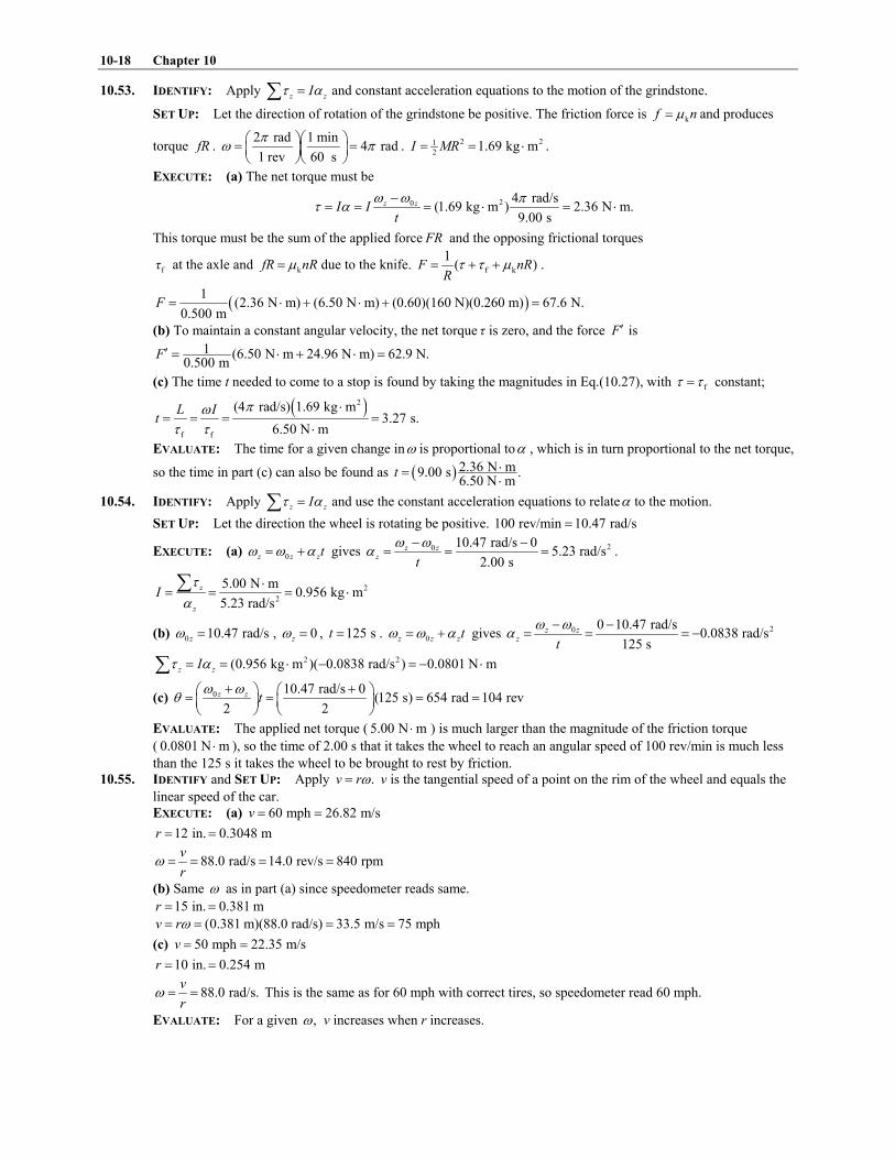
10-18 Chapter 10
10.53. IDENTIFY: Apply z zI! /"( and constant acceleration equations to the motion of the grindstone.
SET UP: Let the direction of rotation of the grindstone be positive. The friction force is kf n:" and produces
torque fR . 2 rad 1 min
4 rad1 rev 60 s
10 12 32 3" "4 54 5
6 76 7. 2 21
21.69 kg mI MR" " % .
EXECUTE: (a) The net torque must be
20 4 rad/s(1.69 kg m ) 2.36 N m.
9.00 s
z zI It
0 0 1! /
&" " " % " %
This torque must be the sum of the applied force FR and the opposing frictional torques
f# at the axle and kfR nR:" due to the knife. f k
1( )F nR
R! ! :" ' ' .
8 91(2.36 N m) (6.50 N m) (0.60)(160 N)(0.260 m) 67.6 N.
0.500 mF " % ' % ' "
(b) To maintain a constant angular velocity, the net torque # is zero, and the force is F =
1 (6.50 N m 24.96 N m) 62.9 N.0.500 m
F = " % ' % "
(c) The time t needed to come to a stop is found by taking the magnitudes in Eq.(10.27), with f! !" constant;
8 92
f f
(4 rad/s) 1.69 kg m3.27 s.
6.50 N m
L It
10! !
%" " " "
%
EVALUATE: The time for a given change in0 is proportional to/ , which is in turn proportional to the net torque,
so the time in part (c) can also be found as 8 9 2.36 N m9.00 s .6.50 N m
t %"%
10.54. IDENTIFY: Apply z zI! /"( and use the constant acceleration equations to relate/ to the motion.
SET UP: Let the direction the wheel is rotating be positive. 100 rev/min 10.47 rad/s"
EXECUTE: (a) 0z z zt0 0 /" ' gives 20 10.47 rad/s 05.23 rad/s
2.00 s
z zz
t
0 0/
& &" " " .
2
2
5.00 N m0.956 kg m
5.23 rad/s
z
z
I!
/%
" " " %(
(b) 0 10.47 rad/sz0 " , 0z0 " , 125 st " . 0z z zt0 0 /" ' gives 20 0 10.47 rad/s0.0838 rad/s
125 s
z zz
t
0 0/
& &" " " &
2 2(0.956 kg m )( 0.0838 rad/s ) 0.0801 N mz zI! /" " % & " & %(
(c) 0 10.47 rad/s 0(125 s) 654 rad 104 rev
2 2
z z t0 0
<' '2 3 2 3" " " "4 5 4 5
6 7 6 7
EVALUATE: The applied net torque ( 5.00 N m% ) is much larger than the magnitude of the friction torque
( 0.0801 N m% ), so the time of 2.00 s that it takes the wheel to reach an angular speed of 100 rev/min is much less
than the 125 s it takes the wheel to be brought to rest by friction.
10.55. IDENTIFY and SET UP: Apply .v r0" v is the tangential speed of a point on the rim of the wheel and equals the
linear speed of the car.
EXECUTE: (a) 60 mph 26.82 m/sv " "
12 in. 0.3048 mr " "
88.0 rad/s 14.0 rev/s 840 rpmv
r0 " " " "
(b) Same 0 as in part (a) since speedometer reads same.
15 in. 0.381 mr " "
(0.381 m)(88.0 rad/s) 33.5 m/s 75 mphv r0" " " "
(c) 50 mph 22.35 m/sv " "
10 in. 0.254 mr " "
88.0 rad/s.v
r0 " " This is the same as for 60 mph with correct tires, so speedometer read 60 mph.
EVALUATE: For a given ,0 v increases when r increases.

Dynamics of Rotational Motion 10-19
10.56. IDENTIFY: The kinetic energy of the disk is 2 21 1cm2 2
K Mv I0" ' . As it falls its gravitational potential energy
decreases and its kinetic energy increases. The only work done on the disk is the work done by gravity, so
1 1 2 2K U K U' " ' .
SET UP: 2 21
cm 2 12( )I M R R" ' , where 1 0.300 mR " and 2 0.500 mR " . cm 2v R 0" . Take 1 0y " , so
2 1.20 my " & .
EXECUTE: 1 1 2 2K U K U' " ' . 1 0K " , 1 0U " . 2 2K U" & . 2 21 1cm cm 22 2
Mv I Mgy0' " & .
8 92 2 2 21 1cm 1 2 cm cm2 4
1 [ / ] 0.340I M R R v Mv0 " ' " . Then 2
cm 20.840Mv Mgy" & and
2
2cm
(9.80 m/s )( 1.20 m)3.74 m/s
0.840 0.840
gyv
& & &" " "
EVALUATE: A point mass in free-fall acquires a speed of 4.85 m/s after falling 1.20 m. The disk has a value of
cmv that is less than this, because some of the original gravitational potential energy has been converted to
rotational kinetic energy.
10.57. IDENTIFY: Use z zI! /"( to find the angular acceleration just after the ball falls off and use conservation of
energy to find the angular velocity of the bar as it swings through the vertical position.
SET UP: The axis of rotation is at the axle. For this axis the bar has 21bar12
I m L" , where bar 3.80 kgm " and
0.800 mL " . Energy conservation gives 1 1 2 2K U K U' " ' . The gravitational potential energy of the bar doesn�t
change. Let 1 0y " , so 2 / 2y L" & .
EXECUTE: (a) ball ( / 2)z m g L! " and 2 21ball bar bar ball12
( / 2)I I I m L m L" ' " ' . z zI! /"( gives
ball ball
2 21bar ball ball bar12
( / 2) 2
( / 2) /3z
m g L g m
m L m L L m m/
2 3" " 4 5
' '6 7and
222(9.80 m/s ) 2.50 kg
16.3 rad/s0.800 m 2.50 kg [3.80 kg]/3
z/2 3
" "4 5'6 7.
(b) As the bar rotates, the moment arm for the weight of the ball decreases and the angular acceleration of the bar
decreases.
(c) 1 1 2 2K U K U' " ' . 2 20 K U" ' . 21bar ball ball2
( ) ( / 2)I I m g L0' " & & .
2
ball ball
2 2
ball bar ball bar
4 9.80 m/s 4[2.50 kg]
/ 4 /12 /3 0.800 m 2.50 kg [3.80 kg]/3
m gL g m
m L m L L m m0
2 3 2 3" " "4 5 4 5' ' '6 76 7
5.70 rad/s0 " .
EVALUATE: As the bar swings through the vertical, the linear speed of the ball that is still attached to the bar is
(0.400 m)(5.70 rad/s) 2.28 m/sv " " . A point mass in free-fall acquires a speed of 2.80 m/s after falling 0.400 m;
the ball on the bar acquires a speed less than this.
10.58. IDENTIFY: Use z zI! /"( to find ,z/ and then use the constant z/ kinematic equations to solve for t.
SET UP: The door is sketched in Figure 10.58.
EXECUTE: (220 N)(1.25 m) 275 N mz Fl! " " " %(
From Table 9.2(d), 21
3I Ml"
2 2 21
3(750 N/9.80 m/s )(1.25 m) 39.9 kg mI " " %
Figure 10.58
z zI! /"( so 2
2
275 N m6.89 rad/s
39.9 kg m
z
zI
!/
%" " "
%(
SET UP: 26.89 rad/s ;z/ " 0 90 ( rad/180 ) /2 rad;< < 1 1& " $ $ " 0 0z0 " (door initially at rest); ?t "
210 0 2z zt t< < 0 /& " '
EXECUTE: 0
2
2( ) 2( / 2 rad)0.675 s
6.89 rad/sz
t< < 1/&
" & "
EVALUATE: The forces and the motion are connected through the angular acceleration.
10.59. IDENTIFY: sinrF! #"
SET UP: Let x be the distance from the left end of the rod where the string is attached. For the value of x
where ( )f x is a maximum, / 0df dx " .

10-20 Chapter 10
EXECUTE: (a) From geometric consideration, the lever arm and the sine of the angle between and F r""!
!
are both
maximum if the string is attached at the end of the rod.
(b) In terms of the distance x where the string is attached, the magnitude of the torque is 2 2.Fxh x h' This
function attains its maximum at the boundary, where ,x h" so the string should be attached at the right end of
the rod.
(c) As a function of x, l and h, the torque has magnitude2 2
.( 2)
xhF
x l h! "
& ' Differentiating! with respect to x
and setting equal to zero gives maxx 2( 2)(1 (2 ) ).l h l" ' This will be the point at which to attach the string unless
2 ,h lD in which case the string should be attached at the furthest point to the right, .x l"
EVALUATE: In part (a) the maximum torque is independent of h. In part (b) the maximum torque is independent
of l. In part (c) the maximum torque depends on both h and l.
10.60. IDENTIFY: Apply z zI! /"( , where z! is due to the gravity force on the object.
SET UP: rod clayI I I" ' . 21rod 3
I ML" . In part (b), 2
clayI ML" . In part (c), clay 0I " .
EXECUTE: (a) A distance 4L from the end with the clay.
(b) In this case 2(4 3)I ML" and the gravitational torque is (3 4)(2 )sin (3 2)sin ,L Mg Mg L< <" so
(9 8 )sin .g L/ <"
(c) In this case 2(1 3)I ML" and the gravitational torque is ( 4)(2 )sin ( 2)sin ,L Mg Mg L< <" so (3 2 )sin .g L/ <"
This is greater than in part (b).
(d) The greater the angular acceleration of the upper end of the cue, the faster you would have to react to overcome
deviations from the vertical.
EVALUATE: In part (b), I is 4 times larger than in part (c) and ! is 3 times larger. / I/ !" , so the net effect is
that / is smaller in (b) than in (c).
10.61. IDENTIFY: Calculate W using the procedure specified in the problem. In part (c) apply the work-energy theorem.
In part (d), tana R/" and z zI! /"( . 2
rada R0" .
SET UP: Let < be the angle the disk has turned through. The moment arm for F is cosR < .
EXECUTE: (a) The torque is cos .FR! <" 2
0cos W FR d FR
1< <" "E .
(b) In Eq.(6.14), dl is the horizontal distance the point moves, and so ,W F dl FR" "E the same as part (a).
(c) From 2 2
2 ( 4) , 4 .K W MR F MR0 0" " "
(d) The torque, and hence the angular acceleration, is greatest when 0,< " at which point ( ) 2I F MR/ !" " , and
so the maximum tangential acceleration is 2 .F M
(e) Using the value for 0 found in part (c), 2
rad 4 .a R F M0" "
EVALUATE: 2
tana R0" is maximum initially, when the moment arm for F is a maximum, and it is zero after the
disk has rotated one-quarter of a revolution. rada is zero initially and is a maximum at the end of the motion, after
the disk has rotated one-quarter of a revolution.
10.62. IDENTIFY: Apply m"(F a!
!
to the crate and z zI! /"( to the cylinder. The motions are connected by
(crate) (cylinder).a R/"
SET UP: The force diagram for the crate is given in Figure 10.62a.
EXECUTE: y yF ma"(
T mg ma& "
2 2( ) 50 kg(9.80 m/s 0.80 m/s ) 530 NT m g a" ' " ' "
Figure 10.62a

Dynamics of Rotational Motion 10-21
SET UP: The force diagram for the cylinder is given in Figure 10.62b.
EXECUTE: z zI! /"(
,zFl TR I/& " where 0.12 ml " and 0.25 mR "
a R/" so /z a R/ "
/Fl TR Ia R" '
Figure 10.62b
2 20.25 m (2.9 kg m )(0.80 m/s )530 N 1200 N
0.12 m (0.25 m)(0.12 m)
R IaF T
l Rl
%2 3 2 3" ' " ' "4 5 4 56 7 6 7
EVALUATE: The tension in the rope is greater than the weight of the crate since the crate accelerates upward. If F
were applied to the rim of the cylinder (l " 0.25 m), it would have the value 567 N.F " This is greater than T
because it must accelerate the cylinder as well as the crate. And F is larger than this because it is applied closer to
the axis than R so has a smaller moment arm and must be larger to give the same torque.
10.63. IDENTIFY: Apply ext cmm"(F a!
!
and cmz zI! /"( to the roll.
SET UP: At the point of contact, the wall exerts a friction force f directed downward and a normal force n
directed to the right. This is a situation where the net force on the roll is zero, but the net torque is not zero.
EXECUTE: (a) Balancing vertical forces, rod cos ,F f w F< " ' ' and balancing horizontal forces
rod ksin . With ,F n f n< :" " these equations become rod kcos ,F n F w< :" ' ' rod sin . F n< " Eliminating n and
solving for rodF gives
2
rod
k
(16.0 kg) (9.80 m/s ) (40.0 N)266 N.
cos sin cos 30 (0.25)sin30
w FF
< : <' '
" " "& $ & $
(b) With respect to the center of the roll, the rod and the normal force exert zero torque. The magnitude of the net
torque is k( ) , and F f R f n:& " may be found by insertion of the value found for rodF into either of the above
relations; i.e., k rod sin 33.2 N. f F: <" " Then,
22
2
(40.0 N 31.54 N)(18.0 10 m)4.71 rad/s .
(0.260 kg m )I
!/
&& ," " "
%
EVALUATE: If the applied force F is increased, rodF increases and this causes n and f to increase. The angle
# changes as the amount of paper unrolls and this affects / for a given F.
10.64. IDENTIFY: Apply z zI! /"( to the flywheel and m"(F a!
!
to the block. The target variables are the tension in
the string and the acceleration of the block.
(a) SET UP: Apply z zI! /"( to the rotation of the flywheel about the axis. The free-body diagram for the
flywheel is given in Figure 10.64a.
EXECUTE: The forces n and Mg act
at the axis so have zero torque.
z TR! "(
zTR I/"
Figure 10.64a

10-22 Chapter 10
SET UP: Apply m"(F a!
!
to the translational motion of the block. The free-body diagram for the block is given
in Figure 10.64b.
EXECUTE: y yF ma"(
cos36.9 0n mg& $ "
cos36.9n mg" $
k k k cos36.9f n mg: :" " $
Figure 10.64b
x xF ma"(
ksin36.9 cos36.9mg T mg ma:$ & & $ "
k(sin36.9 cos36.9 )mg T ma:$ & $ & "
But we also know that block wheel ,a R/" so / .a R/ " Using this in the z zI! /"( equation gives /TR Ia R" and
2( / ) .T I R a" Use this to replace T in the x xF ma"( equation:
2
k(sin36.9 cos36.9 ) ( / )mg I R a ma:$ & $ & "
k
2
(sin36.9 cos36.9 )
/
mga
m I R
:$ & $"
'
22
2 2
(5.00 kg)(9.80 m/s )(sin36.9 (0.25)cos36.9 )1.12 m/s
5.00 kg 0.500 kg m /(0.200 m)a
$ & $" "
' %
(b) 2
2
2
0.500 kg m(1.12 m/s ) 14.0 N
(0.200 m)T
%" "
EVALUATE: If the string is cut the block will slide down the incline with 2
ksin36.9 cos36.9 3.92 m/s .a g g:" $ & $ " The actual acceleration is less than this because sin36.9mg $ must also
accelerate the flywheel. ksin36.9 19.6 N.mg f$ & " T is less than this; there must be more force on the block
directed down the incline than up then incline since the block accelerates down the incline.
10.65. IDENTIFY: Apply m"(F a!
!
to the block and z zI! /"( to the combined disks.
SET UP: For a disk, 21disk 2
I MR" , so I for the disk combination is 3 22.25 10 kg m .I &" , %
EXECUTE: For a tension T in the string, and .amg T ma TR I IR
/& " " " Eliminating T and solving for a gives
2 2,
/ 1 /
m ga g
m I R I mR" "
' ' where m is the mass of the hanging block and R is the radius of the disk to which the
string is attached.
(a) With 1.50m " kg and 2 22.50 10 m, 2.88 m/s .R a&" , "
(b) With 1.50m " kg and 2 25.00 10 m, 6.13 m/s .R a&" , "
The acceleration is larger in case (b); with the string attached to the larger disk, the tension in the string is capable
of applying a larger torque.
EVALUATE: /v R0 " , where v is the speed of the block and 0 is the angular speed of the disks. When R is
larger, in part (b), a smaller fraction of the kinetic energy resides with the disks. The block gains more speed as it
falls a certain distance and therefore has a larger acceleration.
10.66. IDENTIFY: Apply both m"(F a!
!
and z zI! /"( to the motion of the roller. Rolling without slipping means
cm .a R/" Target variables are cma and f.

Dynamics of Rotational Motion 10-23
SET UP: The free-body diagram for the roller is given in Figure 10.66.
EXECUTE: Apply m"(F a!
!
to the
translational motion of the center of mass:
x xF ma"(
cmF f Ma& "
Figure 10.66
Apply z zI! /"( to the rotation about the center of mass:
z fR! "(
thin-walled hollow cylinder: 2I MR"
Then z zI! /"( implies 2 .fR MR /"
But cm ,R/ /" so cm.f Ma"
Using this in the x xF ma"( equation gives cm cmF Ma Ma& "
cm / 2 ,a F M" and then cm ( / 2 ) / 2.f Ma M F M F" " "
EVALUATE: If the surface were frictionless the object would slide without rolling and the acceleration would be
cm / .a F M" The acceleration is less when the object rolls.
10.67. IDENTIFY: Apply m(F = a!
!
to each object and apply z zI! /"( to the pulley.
SET UP: Call the 75.0 N weight A and the 125 N weight B. Let AT and BT be the tensions in the cord to the left
and to the right of the pulley. For the pulley, 21
2I MR" , where 50.0 NMg " and 0.300 mR " . The 125 N weight
accelerates downward with acceleration a, the 75.0 N weight accelerates upward with acceleration a and the pulley
rotates clockwise with angular acceleration / , where a R/" .
EXECUTE: m(F = a!
!
applied to the 75.0 N weight gives A A AT w m a& " . m(F = a!
!
applied to the 125.0 N
weight gives B B Bw T m a& " . z zI! /"( applied to the pulley gives 21
2( ) ( )B A zT T R MR /& " and 1
2B AT T M& " .
Combining these three equations gives ( / 2)B A A Bw w m m M a& " ' ' and
pulley
125 N 75.0 N0.222
/ 2 75.0 N 125 N 25.0 N
B A
A B
w wa g g g
w w w
2 3& &2 3" " "4 5 4 54 5' ' ' '6 76 7. (1 / ) 1.222 91.65 NA A AT w a g w" ' " " .
(1 / ) 0.778 97.25 NB B BT w a g w" & " " . m(F = a!
!
applied to the pulley gives that the force F applied by the hook
to the pulley is pulley 239 NA BF T T w" ' ' " . The force the ceiling applies to the hook is 239 N.
EVALUATE: The force the hook exerts on the pulley is less than the total weight of the system, since the net
effect of the motion of the system is a downward acceleration of mass.
10.68. IDENTIFY: This problem can be done either with conservation of energy or with ext .m"(F a!
!
We will do it both
ways.
(a) SET UP: (1) Conservation of energy: 1 1 other 2 2.K U W K U' ' " '
Take position 1 to be the location of the disk
at the base of the ramp and 2 to be where the
disk momentarily stops before rolling back
down, as shown in Figure 10.68a.
Figure 10.68a
Take the origin of coordinates at the center of the disk at position 1 and take y' to be upward. Then 1 0y " and
2 sin30 ,y d" $ where d is the distance that the disk rolls up the ramp. �Rolls without slipping� and neglect rolling
friction says 0;fW " only gravity does work on the disk, so other 0W "

10-24 Chapter 10
EXECUTE: 1 1 0U Mgy" "
2 21 11 1 cm 12 2
K Mv I 0" ' (Eq.10.11). But 1 1 /v R0 " and 21cm 2
,I MR" so 8 92 2 2 21 1 1 1cm 1 1 12 2 2 4
( / ) .I MR v R Mv0 " " Thus
2 2 231 11 1 1 12 4 4
.K Mv Mv Mv" ' "
2 2 sin30U Mgy Mgd" " $
2 0K " (disk is at rest at point 2).
Thus 2314
sin30Mv Mgd" $
2 2
1
2
3 3(2.50 m/s)0.957 m
4 sin30 4(9.80 m/s )sin30
vd
g" " "
$ $
SET UP: (2) force and acceleration The free-body diagram is given in Figure 10.68b.
EXECUTE: Apply x xF ma"( to the
translational motion of the center of mass:
cmsinMg f Ma< & "
Apply z zI! /"( to the rotation about the
center of mass:
8 921
2 zf R MR /"
1
2 zf MR/"
Figure 10.68b
But cma R/" in this equation gives 1cm2
.f Ma" Use this in the x xF ma"( equation to eliminate f.
1cm cm2
sinMg Ma Ma< & "
M divides out and 3cm2
sin .a g <" 2 22 2cm 3 3
sin (9.80 m/s )sin30 3.267 m/sa g <" " $ "
SET UP: Apply the constant acceleration equations to the motion of the center of mass. Note that in our
coordinates the positive x-direction is down the incline.
0 2.50 m/sxv " & (directed up the incline); 23.267 m/s ;xa " '
0xv " (momentarily comes to rest); 0 ?x x& "
2 2
0 02 ( )x x xv v a x x" ' &
EXECUTE: 2 2
00 2
( 2.50 m/s)0.957 m
2 2(3.267 m/s )
x
x
vx x
a
&& " & " & " &
(b) EVALUATE: The results from the two methods agree; the disk rolls 0.957 m up the ramp before it stops.
The mass M enters both in the linear inertia and in the gravity force so divides out. The mass M and radius R enter
in both the rotational inertia and the gravitational torque so divide out.
10.69. IDENTIFY: Apply ext cmm"(F a!
!
to the motion of the center of mass and apply cmz zI! /"( to the rotation about
the center of mass.
SET UP: 8 92 21
22I MR MR" " . The moment arm for T is b.
EXECUTE: The tension is related to the acceleration of the yo-yo by (2 ) (2 ) ,m g T m a& " and to the angular
acceleration by .aTb I Ib
/" " Dividing the second equation by b and adding to the first to eliminate T yields
2 2 2
2 2 2,
(2 ) 2 ( ) 2
ma g g g
m I b R b b R b/" " "
' ' '. The tension is found by substitution into either of the two
equations:
2
2 2 2
2 ( ) 2(2 )( ) (2 ) 1 2 .
2 ( ) 2 ( ) (2( ) 1)
R b mgT m g a mg mg
R b R b b R
2 3" & " & " "4 5
' ' '6 7
EVALUATE: 0a B when 0b B . As b RB , 2 /3a gB .

Dynamics of Rotational Motion 10-25
10.70. IDENTIFY: Apply conservation of energy to the motion of the shell, to find its linear speed v at points A and B.
Apply m(F = a!
!
to the circular motion of the shell in the circular part of the track to find the normal force exerted
by the track at each point. Since r R)) the shell can be treated as a point mass moving in a circle of radius R when
applying m(F = a!
!
. But as the shell rolls along the track, it has both translational and rotational kinetic energy.
SET UP: 1 1 2 2K U K U' " ' . Let 1 be at the starting point and take 0y " to be at the bottom of the track, so
1 0y h" . 2 21 1
2 2K mv I0" ' . 22
3I mr" and /v r0 " , so 25
6K mv" . During the circular motion, 2
rad /a v R" .
EXECUTE: (a) m(F = a!
!
at point A gives 2v
n mg mR
' " . The minimum speed for the shell not to fall off the
track is when 0n B and 2v gR" . Let point 2 be A, so 2 2y R" and 2
2v mR" . Then 1 1 2 2K U K U' " ' gives
50 6
2 ( )mgh mgR m gR" ' . 5 170 6 6
(2 )h R R" ' " .
(b) Let point 2 be B, so 2y R" . Then 1 1 2 2K U K U' " ' gives 250 26
mgh mgR mv" ' . With 17
6h R" this gives
2 11
5v gR" . Then m(F = a
!
!
at B gives 2
11
5
vn m mg
R" " .
(c) Now 21
2K mv" instead of 25
6mv . The shell would be moving faster at A than with friction and would still make
the complete loop.
(d) In part (c): 210 2
(2 )mgh mg R mv" ' . 170 6
h R" gives 2 5
3v gR" . m(F = a
!
!
at point A gives 2v
mg n mR
' " and
2
2
3
vn m g mg
R
2 3" & "4 5
6 7. In part (a), 0n " , since at this point gravity alone supplies the net downward force that is
required for the circular motion.
EVALUATE: The normal force at A is greater when friction is absent because the speed of the shell at A is greater
when friction is absent than when there is rolling without slipping.
10.71. IDENTIFY: Consider the direction of the net force and the sense of the net torque in each case.
SET UP: The free-body diagram in each case is shown in Figure 10.71.
EXECUTE: In the first case, B
F and the friction force act in opposite directions, and the friction force causes a
larger torque to tend to rotate the yo-yo to the right. The net force to the right is the difference ,F f& so the net
force is to the right while the net torque causes a clockwise rotation. For the second case, both the torque and the
friction force tend to turn the yo-yo clockwise, and the yo-yo moves to the right. In the third case, friction tends to
move the yo-yo to the right, and since the applied force is vertical, the yo-yo moves to the right.
EVALUATE: In the first case the torque due to friction must be larger than the torque due to F, so the net torque is
clockwise. In the third case the torque due to F must be larger than the torque due to f, so the net torque will be clockwise.
Figure 10.71
10.72. IDENTIFY: Apply ext cmm"(F a!
!
to the motion of the center of mass and cmz zI! /"( to the rotation about the
center of mass.
SET UP: For a hoop, 2I MR" . For a solid disk, 21
2I MR" .
EXECUTE: (a) Because there is no vertical motion, the tension is just the weight of the hoop:
8 98 90.180 kg 9.8 N kg 1.76 NT Mg" " " .
(b) Use to find .I! / /" The torque is 2, so / / , RT RT I RT MR T MR Mg MR/ " " " " so
2 2/ (9.8 m/s ) (0.08 m) 122.5 rad/sg R/ " " " .
(c) 29.8 m sa R/" "
(d) T would be unchanged because the mass M is the same, and a/ would be twice as great because I is now 21
2.MR
EVALUATE: tana for a point on the rim of the hoop or disk equals a for the free end of the string. Since I is
smaller for the disk, the same value of T produces a greater angular acceleration.

10-26 Chapter 10
10.73. IDENTIFY: Apply z zI! /"( to the cylinder or hoop. Find a for the free end of the cable and apply constant
acceleration equations.
SET UP: tana for a point on the rim equals a for the free end of the cable, and tana R/" .
EXECUTE: (a) tan and z zI a R! / /" "( gives 2 2 tan1 1
2 2
aFR MR MR
R/ 2 3" " 4 5
6 7. 2
tan
2 200 N50 m/s
4.00 kg
Fa
M" " " .
Distance the cable moves: 210 0 2x xx x v t a t& " ' gives 8 92 21
50 m 50 m/s2
t" and 1.41 st " .
8 98 92
0 0 50 m/s 1.41 s 70.5 m sx x xv v a t" ' " ' " .
(b) For a hoop, 2 ,I MR" which is twice as large as before, so tanand a/ would be half as large. Therefore the time
would be longer by a factor of 2 . For the speed, 2 2
0 2 ,x x xv v a x" ' in which x is the same, so xv would be half as
large since xa is smaller.
EVALUATE: The acceleration a that is produced depends on the mass of the object but is independent of its
radius. But a depends on how the mass is distributed and is different for a hoop versus a cylinder.
10.74. IDENTIFY: Use projectile motion to find the speed v the marble needs at the edge of the pit to make it to the level
ground on the other side. Apply conservation of energy to the motion down the hill in order to relate the initial
height to the speed v at the edge of the pit. other 0W " so conservation of energy gives i i f fK U K U' " ' .
SET UP: In the projectile motion the marble must travel 36 m horizontally while falling vertically 20 m. Let y'
be downward. For the motion down the hill, let f 0y " so f 0U " and iy h" . i 0K " . Rolling without slipping
means v R0" . 2 2 2 2 2 271 1 1 2 1cm2 2 2 5 2 10
( )K I mv mR mv mv0 0" ' " ' " .
EXECUTE: (a) Projectile motion: 0 0yv " . 29.80 m/sya " . 0 20 my y& " . 210 0 2y yy y v t a t& " ' gives
02( )2.02 s
y
y yt
a
&" " . Then 0 0xx x v t& " gives 0
0
36 m17.8 m/s
2.02 sx
x xv v
t
&" " " " .
Motion down the hill: i fU K" . 27
10mgh mv" .
2 2
2
7 7(17.8 m/s)22.6 m
10 10(9.80 m/s )
vh
g" " " .
(b) 2 21 1
2 5I mv0 " , independent of R. I is proportional to 2R but 20 is proportional to 21/ R for a given
translational speed v.
(c) The object still needs 17.8 m/sv " at the bottom of the hill in order to clear the pit. But now 21f 2
K mv" and
2
16.6 m2
vh
g" " .
EVALUATE: The answer to part (a) also does not depend on the mass of the marble. But, it does depend on how
the mass is distributed within the object. The answer would be different if the object were a hollow spherical shell.
In part (c) less height is needed to give the object the same translational speed because in (c) none of the energy
goes into rotational motion.
10.75. IDENTIFY: Apply conservation of energy to the motion of the boulder.
SET UP: 2 21 1
2 2K mv I0" ' and v R0" when there is rolling without slipping. 22
5I mR" .
EXECUTE: Break into 2 parts, the rough and smooth sections.
Rough: 2 21 11 2 2
mgh mv I0" ' .
2
2 2
1
1 1 2
2 2 5
vmgh mv mR
R
2 32 3" ' 4 54 56 76 7
. 2
1
10
7v gh" .
Smooth: Rotational kinetic energy does not change. 2 2
2 rot Bottom rot
1 1
2 2mgh mv K mv K' ' " ' . 2
2 1 B
1 10 1
2 7 2gh gh v
2 3' "4 56 7
.
2 2
B 1 2
10 102 (9.80 m/s )(25 m) 2(9.80 m/s )(25 m) 29.0 m/s
7 7v gh gh" ' " ' " .
EVALUATE: If all the hill was rough enough to cause rolling without slipping, B
10(50 m) 26.5 m/s
7v g" " . A
smaller fraction of the initial gravitational potential energy goes into translational kinetic energy of the center of
mass than if part of the hill is smooth. If the entire hill is smooth and the boulder slides without slipping,
B 2 (50 m) 31.3 m/sv g" " . In this case all the initial gravitational potential energy goes into the kinetic energy of
the translational motion.

Dynamics of Rotational Motion 10-27
10.76. IDENTIFY: Apply conservation of energy to the motion of the ball as it rolls up the hill. After the ball leaves the
edge of the cliff it moves in projectile motion and constant acceleration equations can be used.
(a) SET UP: Use conservation of energy to find the speed 2v of the ball just before it leaves the top of the cliff.
Let point 1 be at the bottom of the hill and point 2 be at the top of the hill. Take 0y " at the bottom of the hill, so
1 0y " and 2 28.0 m.y "
EXECUTE: 1 1 2 2K U K U" " '
2 2 2 21 1 1 11 1 2 2 22 2 2 2
mv I mgy mv I0 0' " ' '
Rolling without slipping means /v r0 " and 8 92 2 2 21 1 2 1
2 2 5 5( / )I mr v r mv0 " "
2 27 71 2 210 10
mv mgy mv" '
2 102 1 27
15.26 m/sv v gy" & "
SET UP: Consider the projectile motion of the ball, from just after it leaves the top of the cliff until just before it
lands. Take y' to be downward. Use the vertical motion to find the time in the air:
0 0,yv " 29.80 m/s ,ya " 0 28.0 m,y y& " ?t "
EXECUTE: 21
0 0 2y yy y v t a t& " ' gives 2.39 st "
During this time the ball travels horizontally
0 0 (15.26 m/s)(2.39 s) 36.5 m.xx x v t& " " "
Just before it lands, 0 23.4 m/sy y yv v a t" ' " and 0 15.3 m/sx xv v" "
2 2 28.0 m/sx yv v v" ' "
(b) EVALUATE: At the bottom of the hill, / (25.0 m/s) / .v r r0 " " The rotation rate doesn�t change while the ball
is in the air, after it leaves the top of the cliff, so just before it lands (15.3 m/s) / .r0 " The total kinetic energy is
the same at the bottom of the hill and just before it lands, but just before it lands less of this energy is rotational
kinetic energy, so the translational kinetic energy is greater.
10.77. IDENTIFY: Apply conservation of energy to the motion of the wheel. 2 21 1
2 2K mv I0" ' .
SET UP: No slipping means that .v R0 " Uniform density means r s2 and m R m RF 1 F" " , where rm is the
mass of the rim and sm is the mass of each spoke. For the wheel, rim spokesI I I" ' . For each spoke, 21s3
I m R" .
EXECUTE: (a) 2 21 1
2 2mgh mv I0" ' . 2 2
rim spokes r s
1 6
3I I I m R m R
2 3" ' " ' 4 56 7
Also, 8 9r s 2 6 2 3m m m R R R1 F F F 1" ' " ' " ' . Substituting into the conservation of energy equation gives
8 9 8 98 98 92 2 2 21 1 12 3 2 3 2 6
2 2 3R gh R R R R RRF 1 F 1 0 1 F 1 0
* +2 3' " ' ' ' 4 5G H6 7- .
.
8 98 9
8 98 98 98 9 8 9
2
22
3 9.80 m s 58.0 m3124 rad s
2 0.210 m 2
gh
R
110
1 1
''" " "
' 'and 26.0 m sv R0" "
(b) Doubling the density would have no effect because it does not appear in the answer. 0 is inversely proportional
to R so doubling the diameter would double the radius which would reduce by half, but0 v R0" would be
unchanged.
EVALUATE: Changing the masses of the rim and spokes by different amounts would alter the speed v at the
bottom of the hill.
10.78. IDENTIFY: Apply v R0" .
SET UP: For the antique bike, v is the same for points on the rim of each wheel and equals the linear speed of the
bike. 1 rev 2 rad1" .
EXECUTE: (a) The front wheel is turning at 1.00 rev s 2 rad s.0 1" " (0.330 m)(2 rad s) 2.07 sv r0 1" " " .
(b) (2.07 m s) (0.655 m) 3.16 rad s 0.503 rev sv r0 " " " "
(c) (2.07 m s) (0.220 m) 9.41 rad s 1.50 rev sv r0 " " " "
EVALUATE: Since the front wheel has a larger radius for the antique bike, that wheel doesn't have to rotate at as
many rev/s to achieve the same linear speed of the bike.

10-28 Chapter 10
10.79. IDENTIFY: Apply conservation of energy to the motion of the ball. Once the ball leaves the track the ball moves
in projectile motion.
SET UP: The ball has 22
5I mR" ; the silver dollar has 21
2I mR" . For the projectile motion take y' downward,
so 0xa " and ya g" ' .
EXECUTE: (a) The kinetic energy of the ball when it leaves the track (when it is still rolling without slipping) is 2(7 10)mv and this must be the work done by gravity, W mgh" , so 10 7.v gh" The ball is in the air for a time
2 , so 20 7.t y g x vt hy" " "
(b) The answer does not depend on g, so the result should be the same on the moon.
(c) The presence of rolling friction would decrease the distance.
(e) For the dollar coin, modeled as a uniform disc, 2(3 4) , and so 8 3.K mv x hy" "
EVALUATE: The sphere travels a little farther horizontally, because its moment of inertia is a smaller fraction of 2MR than for the disk. The result is independent of the mass and radius of the object but it does depend on how
that mass is distributed within the object.
10.80. IDENTIFY and SET UP: Apply conservation of energy to the motion of the ball. The ball ends up with both
translational and rotational kinetic energy. Use Fig.(10.13) in the textbook to relate the speed of different points on
the ball to cm.v
EXECUTE: (a) 2 21 1el 2 2
(400 N m)(0.15 m) 4.50 JU kx" " % " and 1 el0.800 3.60 JK U" "
2 21 11 cm cm2 2
K mv I 0" ' rolling without slipping says cm /v R0 "
22cm 5
I mR"
Thus 8 9 8 92 2 2 2 271 1 2 1 11 cm cm cm cm2 2 5 2 5 10
( / )K mv mR v R mv mv" ' " ' "
and 1cm
10 10(3.60 J)9.34 m/s.
7 7(0.0590 kg)
Kv
m" " "
(b) Consider Figure 10.80a.
From Fig.(10.13) in the textbook,
at the top of the ball
cm2 18.7 m/sv v" "
Figure 10.80a
(c)
From Fig.(10.13) in the textbook,
0v " at the bottom of the ball.
Figure 10.80b
(d) The problem says that 2 10.900 3.24 J.U K" " Thus 2 3.24 JU mgh" " and
2
3.24 J 3.24 J5.60 m
(0.0590 kg)(9.80 m/s )h
mg" " "
EVALUATE: Not all the potential energy stored in the spring goes into kinetic energy at the base of the ramp or
into gravitational potential energy at the top of the ramp because of loss of mechanical energy due to negative
work done by friction. If the ball slides without rolling, then 211 cm2
K mv" and cm 11.0 m/s.v " cmv is less than this
when the ball rolls and some of its total kinetic energy is rotational.
10.81. IDENTIFY: /xv dx dt" , /yv dy dt" . /x xa dv dt" , /y ya dv dt" .
SET UP: cos( ) / sin( )d t dt t0 0 0" & . sin( ) / cos( )d t dt t0 0 0" .
EXECUTE: (a) The sketch is shown in Figure 10.81.
(b) R is the radius of the wheel (y varies from 0 to 2R) and T is the period of the wheel�s rotation.
(c) Differentiating, 2 2
1 cosx
R tv
T T
1 1* +2 3" & 4 5G H6 7- .
,
22 2
sinx
ta R
T T
1 12 3 2 3" 4 5 4 56 7 6 7
and 2 2
siny
R tv
T T
1 12 3" 4 56 7
,
22 2
cos .y
ta R
T T
1 12 3 2 3" 4 5 4 56 7 6 7

Dynamics of Rotational Motion 10-29
(d) 2
0 when 2x y
tv v
T
112 3" " "4 5
6 7or any multiple of 2 ,1 so the times are integer multiples of the period T. The
acceleration components at these times are 2
2
40, .x y
Ra a
T
1" "
(e)
2 22 2 2 2
2
2 2 2 4cos sin ,x y
t t Ra a a R
T T T T
1 1 1 12 3 2 3 2 3" ' " ' "4 5 4 5 4 56 7 6 7 6 7
independent of time. This is the magnitude of the
radial acceleration for a point moving on a circle of radius R with constant angular velocity 2 /T1 . For motion that
consists of this circular motion superimposed on motion with constant velocity 8 90 ,"a!
the acceleration due to the
circular motion will be the total acceleration.
EVALUATE: a is independent of time, but v does depend on time.
Figure 10.81
10.82. IDENTIFY: Apply the work-energy theorem to the motion of the basketball. 2 21 1
2 2K mv I0" ' and v R0" .
SET UP: For a thin-walled, hollow sphere 22
3I mR" .
EXECUTE: For rolling without slipping, the kinetic energy is 8 98 9 8 92 2 21 2 5 6 ;m I R v mv' " initially, this is
32.0 J and at the return to the bottom it is 8.0 J. Friction has done 24.0 J& of work, 12.0 J& each going up and
down. The potential energy at the highest point was 20.0 J, so the height above the ground was
8 98 92
20.0 J 3.40 m.0.600 kg 9.80 m s
"
EVALUATE: All of the kinetic energy of the basketball, translational and rotational, has been removed at the point
where the basketball is at its maximum height up the ramp.
10.83. IDENTIFY: Use conservation of energy to relate the speed of the block to the distance it has descended. Then use
a constant acceleration equation to relate these quantities to the acceleration.
SET UP: For the cylinder, 21
2(2 )I M R" , and for the pulley, 21
2I MR" .
EXECUTE: Doing this problem using kinematics involves four unknowns (six, counting the two angular
accelerations), while using energy considerations simplifies the calculations greatly. If the block and the cylinder
both have speed v, the pulley has angular velocity v/R and the cylinder has angular velocity v/2R, the total kinetic
energy is
2 22 2 2 2 21 (2 ) 3
( 2 ) ( ) .2 2 2 2
M R MRK Mv v R v R Mv Mv
* +" ' ' ' "G H
- .
This kinetic energy must be the work done by gravity; if the hanging mass descends a distance y, ,K Mgy" or
2 (2 3) .v gy" For constant acceleration, 2 2 ,v ay" and comparison of the two expressions gives 3.a g"
EVALUATE: If the pulley were massless and the cylinder slid without rolling, 2Mg Ma" and / 2a g" . The
rotation of the objects reduces the acceleration of the block.
10.84. IDENTIFY: Apply z zI! /"( to the drawbridge and calculate z/ . For part (c) use conservation of energy.
SET UP: The free-body diagram for the drawbridge is given in Fig.10.84. For an axis at the lower end, 21
3I ml" .
EXECUTE: (a) z zI! /"( gives 21
3(4.00 m)(cos60.0 ) zmg ml /"! and 2
2
3 (4.00 m)(cos60.0 )0.919 rad/s
(8.00 m)z
g/ " "
!.
(b) z/ depends on the angle the bridge makes with the horizontal. z/ is not constant during the motion and
0z z zt0 0 /" ' cannot be used.
(c) Use conservation of energy. Take 0y " at the lower end of the drawbridge, so i (4.00 m)(sin60.0 )y " ! and
f 0y " . f f i i otherK U K U W' " ' ' gives i fU K" , 21i 2
mgy I0" . 2 21 1i 2 3
( )mgy ml 0" and
2
i6 6(9.80 m/s )(4.00 m)(sin60.0 )1.78 rad/s
8.00 m
gy
l0 " " "
!.

10-30 Chapter 10
EVALUATE: If we incorrectly assume that z/ is constant and has the value calculated in part (a), then
2 2
0 02 ( )z z z0 0 / < <" ' & gives 139 rad/s0 " . The angular acceleration increases as the bridge rotates and the actual
angular velocity is larger than this.
Figure 10.84
10.85. IDENTIFY: Apply conservation of energy to the motion of the first ball before the collision and to the motion of
the second ball after the collision. Apply conservation of angular momentum to the collision between the first ball
and the bar.
SET UP: The speed of the ball just before it hits the bar is 2 15.34 m/s.v gy" " Use conservation of angular
momentum to find the angular velocity 0 of the bar just after the collision. Take the axis at the center of the bar.
EXECUTE: 2
1 (5.00 kg)(15.34 m/s)(2.00 m) 153.4 kg mL mvr" " " %
Immediately after the collision the bar and both balls are rotating together.
2 totL I 0"
2 2 2 2 21 1tot 12 12
2 (8.00 kg)(4.00 m) 2(5.00 kg)(2.00 m) 50.67 kg mI Ml mr" ' " ' " %
2
2 1 153.4 kg mL L" " %
2 tot/ 3.027 rad/sL I0 " "
Just after the collision the second ball has linear speed (2.00 m)(3.027 rad/s) 6.055 m/sv r0" " " and is moving
upward. 21
2mv mgy" gives 1.87 my " for the height the second ball goes.
EVALUATE: Mechanical energy is lost in the inelastic collision and some of the final energy is in the rotation of the bar
with the first ball stuck to it. As a result, the second ball does not reach the height from which the first ball was dropped.
10.86. IDENTIFY: The rings and the rod exert forces on each other, but there is no net force or torque on the system, and
so the angular momentum will be constant.
SET UP: For the rod, 21
12I ML" . For each ring, 2I mr" , where r is their distance from the axis.
EXECUTE: (a) As the rings slide toward the ends, the moment of inertia changes, and the final angular velocity is
given by 2 2 4 21
11 1122 1 1 12 2 3 21
2 212
2 5.00 10 kg m,
2 2.00 10 kg m 4
ML mrI
I ML mr
00 0 0 0
&
&
* +' , %" " " "G H
' , %- . so 2 7.5 rev min.0 "
(b) The forces and torques that the rings and the rod exert on each other will vanish, but the common angular
velocity will be the same, 7.5 rev/min.
EVALUATE: Note that conversion from rev/min to rad/s was not necessary. The angular velocity of the rod
decreases as the rings move away from the rotation axis.
10.87. IDENTIFY: Apply conservation of angular momentum to the collision. Linear momentum is not conserved
because of the force applied to the rod at the axis. But since this external force acts at the axis, it produces no
torque and angular momentum is conserved.
SET UP: The system before and after the collision is sketched in Figure 10.87.
EXECUTE: (a) 1rod4bm m"
EXECUTE: 11 b rod4
( / 2)L m vr m v L" "
11 rod8
L m vL"
2 rod b( )L I I 0" '
21rod rod3
I m L"
2 21b b rod4
( / 2)I m r m L" "
21b rod16
I m L"
Figure 10.87

Dynamics of Rotational Motion 10-31
Thus 1 2L L" gives 8 92 21 1 1rod rod rod8 3 16
m vL m L m L 0" '
191
8 48v L0"
6
19/v L0 "
(b) 2 21 11 rod2 8
K mv m v" "
8 92 2 2 2 21 1 1 1 12 rod b rod rod2 2 2 3 16
( ) (6 /19 )K I I I m L m L v L0 0" " ' " '
8 98 92 2 219 6 312 rod rod2 48 19 152
K m v m v" "
Then 23
rod2 152
211 rod8
3/19.m vK
K m v" "
EVALUATE: The collision is inelastic and 2 1.K K)
10.88. IDENTIFY: Apply Eq.(10.29).
SET UP: The door has 21
3I ml" . The torque applied by the force is avrF , where / 2r l" .
EXECUTE: av av, av and .rF L rF t rJ!I " @ " @ " The angular velocity0 is then
8 9 avav av
213
2 3,
2
l F tL rF t F t
I I ml ml0
@@ @ @" " " " where l is the width of the door. Substitution of the given numeral
values gives 0.514rad s.0 "
EVALUATE: The final angular velocity of the door is proportional to both the magnitude of the average force and
also to the time it acts.
10.89. (a) IDENTIFY: Apply conservation of angular momentum to the collision between the bullet and the board:
SET UP: The system before and after the collision is sketched in Figure 10.89a.
Figure 10.89a
EXECUTE: 1 2L L"
3 2
1 sin (1.90 10 kg)(360 m/s)(0.125 m) 0.0855 kg m /sL mvr mvl# &" " " , " %
2 2 2L I 0"
2 212 board bullet 3
I I I ML mr" ' " '
2 3 2 212 3
(0.750 kg)(0.250 m) (1.90 10 kg)(0.125 m) 0.01565 kg mI &" ' , " %
Then 1 2L L" gives that 2
12 2
2
0.0855 kg m /s5.46 rad/s
0.1565 kg m
L
I0
%" " "
%
(b) IDENTIFY: Apply conservation of energy to the motion of the board after the collision.
SET UP: The position of the board at points 1 and 2 in its motion is shown in Figure 10.89b. Take the origin of
coordinates at the center of the board and y' to be upward, so cm,1 0y " and cm,2 ,y h" the height being asked for.
1 1 other 2 2K U W K U' ' " '
EXECUTE: Only gravity does work, so other 0.W "
211 2
K I0"
1 cm,1 0U mgy" "
2 0K "
2 cm,2U mgy mgh" "
Figure 10.89b

10-32 Chapter 10
Thus 21
2.I mgh0 "
2 2 2
3 2
(0.01565 kg m )(5.46 rad/s)0.0317 m 3.17 cm
2 2(0.750 kg 1.90 10 kg)(9.80 m/s )
Ih
mg
0&
%" " " "
' ,
(c) IDENTIFY and SET UP: The position of the board at points 1 and 2 in its motion is shown in Figure 10.89c.
Apply conservation of energy as in part (b),
except now we want cm,2 0.250 m.y h" "
Solve for the 0 after the collision that is
required for this to happen.
Figure 10.89c
EXECUTE: 21
2I mgh0 "
3 2
2
2 2(0.750 kg 1.90 10 kg)(9.80 m/s )(0.250 m)
0.01565 kg m
mgh
I0
&' ," "
%
15.34 rad/s0 "
Now go back to the equation that results from applying conservation of angular momentum to the collision and
solve for the initial speed of the bullet. 1 2L L" implies bullet 2 2m vl I 0"
2
2 2
3
bullet
(0.01565 kg m )(15.34 rad/s)1010 m/s
(1.90 10 kg)(0.125 m)
Iv
m l
0&
%" " "
,
EVALUATE: We have divided the motion into two separate events: the collision and the motion after the
collision. Angular momentum is conserved in the collision because the collision happens quickly. The board
doesn�t move much until after the collision is over, so there is no gravity torque about the axis. The collision is
inelastic and mechanical energy is lost in the collision. Angular momentum of the system is not conserved during
this motion, due to the external gravity torque. Our answer to parts (b) and (c) say that a bullet speed of 360 m/s
causes the board to swing up only a little and a speed of 1010 m/s causes it to swing all the way over.
10.90. IDENTIFY: Angular momentum is conserved, so 0 0 2 2I I0 0" .
SET UP: For constant mass the moment of inertia is proportional to the square of the radius.
EXECUTE: 2 2
0 0 2 2R R0 0" , or 8 9 8 922 2 2
0 0 0 0 0 0 0 0 0= 2 ,R R R R R R R0 0 0 0 0 0" ' @ ' @ ' @ ' @ where the terms in
R 0@ @ and 2( )0@ have been omitted. Canceling the 2
0 0R 0 term gives
0
0
1.1 cm.2
R "R
"
@@ " & " &
EVALUATE: 0/R R@ and 0/0 0@ are each very small so the neglect of terms containing R 0@ @ or 2( )0@ is an
accurate simplifying approximation.
10.91. IDENTIFY: Apply conservation of angular momentum to the collision between the bird and the bar and apply
conservation of energy to the motion of the bar after the collision.
SET UP: For conservation of angular momentum take the axis at the hinge. For this axis the initial angular
momentum of the bird is bird (0.500 m)m v , where bird 0.500 kgm " and 2.25 m/sv " . For this axis the moment of
inertia is 2 2 21 1bar3 3
(1.50 kg)(0.750 m) 0.281 kg mI m L" " " % . For conservation of energy, the gravitational
potential energy of the bar is bar cmU m gy" , where cmy is the height of the center of the bar. Take cm,1 0y " , so
cm,2 0.375 my " & .
EXECUTE: (a) 1 2L L" gives 21bird bar3
(0.500 m) ( )m v m L 0" .
bird
2 2
bar
3 (0.500 m) 3(0.500 kg)(0.500 m)(2.25 m/s)2.00 rad/s
(1.50 kg)(0.750 m)
m v
m L0 " " " .

Dynamics of Rotational Motion 10-33
(b) 1 1 2 2U K U K' " ' applied to the motion of the bar after the collision gives 2 21 11 bar 22 2
( 0.375 m)I m g I0 0" & ' .
2
2 1 bar
2(0.375 m)m g
I0 0" ' . 2 2
2 2
2(2.00 rad/s) (1.50 kg)(9.80 m/s )(0.375 m) 6.58 rad/s
0.281 kg m0 " ' "
%
EVALUATE: Mechanical energy is not conserved in the collision. The kinetic energy of the bar just after the
collision is less than the kinetic energy of the bird just before the collision.
10.92. IDENTIFY: Angular momentum is conserved, since the tension in the string is in the radial direction and therefore
produces no torque. Apply m"(F a!
!
to the block, with 2
rad /a a v r" " .
SET UP: The block�s angular momentum with respect to the hole is L mvr" .
EXECUTE: The tension is related to the block�s mass and speed, and the radius of the circle, by2
.v
T mr
"
8 922 2 2 22
3 3 3
1.
mvrm v r LT mv
r m r mr mr" " " " The radius at which the string breaks is
8 9 8 98 98 98 98 98 9
2221 13
max max
0.250 kg 4.00 m s 0.800 m,
0.250 kg 30.0 N
mv rLr
mT mT" " " from which 0.440 m.r "
EVALUATE: Just before the string breaks the speed of the rock is 0.800 m
(4.00 m/s) 7.27 m/s0.440 m
2 3 "4 56 7
. We can
verify that 7.27 m/sv " and 0.440 mr " do give 30.0 NT " .
10.93. IDENTIFY and SET UP: Apply conservation of angular momentum to the system consisting of the disk and train.
SET UP: 1 2 ,L L" counterclockwise positive. The motion is sketched in Figure 10.93.
1 0L " (before you switch on the train�s engine;
both the train and the platform are at rest)
2 train diskL L L" '
Figure 10.93
EXECUTE: The train is 1
2(0.95 m) 0.475 m" from the axis of rotation, so for it
2 2 2
t t t (1.20 kg)(0.475 m) 0.2708 kg mI m R" " " %
rel rel t/ (0.600 m/s)/0.475 s 1.263 rad/sv R0 " " "
This is the angular velocity of the train relative to the disk. Relative to the earth t rel d.0 0 0" '
Thus train t t t rel d( ).L I I0 0 0" " '
2 1L L" says disk trainL L" &
disk d d ,L I 0" where 21d d d2
I m R"
21d d d t rel d2
( )m R I0 0 0" & '
2
t reld 2 2 21 1
d d t2 2
(0.2708 kg m )(1.263 rad/s)0.30 rad/s.
(7.00 kg)(0.500 m) 0.2708 kg m
I
m R I
00
%" & " & " &
' ' %
EVALUATE: The minus sign tells us that the disk is rotating clockwise relative to the earth. The disk and train
rotate in opposite directions, since the total angular momentum of the system must remain zero. Note that we
applied 1 2L L" in an inertial frame attached to the earth.
10.94. IDENTIFY: I for the wheel is the sum of the values of I for each of its parts, the rim and each spoke. The total
length of wire is constant. The motion is related to the friction torque by z zI! /"( .
SET UP: 04 2R R L1' " , where R is the radius of the wheel and therefore the length of each of the four spokes.
The mass of a piece is proportional to the length of that piece.
EXECUTE: (a) 0
4 2
LR
1"
'. 2
rim rimI m R" . rim 0 0
0
2 2
4 2
Rm M M
L
1 11
2 3" " 4 5'6 7.
2 3 2
rim 0 0 0 03
2(5.778 10 )
(2 4)I M L M L
11
&" " ,'
. 21spoke spoke3
I m R" . 0spoke 0
0 2 4
R Mm M
L 1" "
'and
2 4 2
spoke 0 0 0 03
1(3.065 10 )
3(2 4)I M L M L
1&" " ,
'. 3 2
rim spoke 0 04 (7.00 10 )I I I M L&" ' " , .

10-34 Chapter 10
(b) 0z z zt0 0 /" ' gives 0z
T
0/ " & . Then z zI! /"( gives 3 2 0
f 0 0(7.00 10 )M LT
0! &" ,
EVALUATE: If the wire were bent into a circle, without spokes, the moment of inertia would be 2
2 3 20 00 0 02
(9.46 10 )(4 2 )
M LM R M L
1&" " ,
'. The actual value of I for the wheel is less than this because the mass in the
spokes is closer to the axis than the rim.
10.95. IDENTIFY and SET UP: Use the methods stipulated in the problem.
EXECUTE: (a) The initial angular momentum with respect to the pivot is ,mvr and the final total moment of
inertia is 2I mr' , so the final angular velocity is 8 92 .mvr mr I0 " '
(b) The kinetic energy after the collision is converted to gravitational potential energy, so
8 9 8 92 21
2mr I M m gh0 ' " ' , or
8 98 92
2
M m gh
mr I0
'"
'.
(c) Substitution of 2& 'r" into the result of part (a) gives 8 9,mv r
m M0 2 3" 4 5'6 7
and into the result of part (b),
2 (1 ),gh r0 " which are consistent with the forms for v.
EVALUATE: 2I Mr" applies approximately when the pendulum consists of a heavy catcher mounted on a light
arm. In the actual apparatus some of the mass is distributed closer to the axis and 2I Mr) .
10.96. IDENTIFY: Apply conservation of momentum to the system of the runner and turntable
SET UP: Let the positive sense of rotation be the direction the turntable is rotating initially.
EXECUTE: The initial angular momentum is 1 1I mRv0 & , with the minus sign indicating that runner�s motion is
opposite the motion of the part of the turntable under his feet. The final angular momentum is 2
2( ), soI mR0 '
1 12 2
I mRv
I mR
00
&"
'.
2
2 2 2
(80 kg m )(0.200 rad s) (55.0 kg)(3.00 m)(2.8 m s)0.776 rad s
(80 kg m ) (55.0 kg)(3.00 m)0
% &" " &
% '.
EVALUATE: The minus sign indicates that the turntable has reversed its direction of motion. This happened
because the man had the larger magnitude of angular momentum initially.
10.97. IDENTIFY: Treat the moon as a point mass, so 2L I mr0 0" " , where r is the distance of the moon from the
center of the earth. Conservation of angular momentum says / 0dL dt " .
SET UP: 2/ 3.0 cm/y 3.0 10 m/ydr dt &" " , . The period of the moon�s orbital motion is 627.3 d 2.36 10 s" , .
83.84 10 mr " , .
EXECUTE: 2 2/ ( ) (2 ) 0d dr d
dL dt mr m r mrdt dt dt
00 0" " ' " , so
2d dr
dt r dt
0 0" & .
6
6
2 rad 2 rad2.66 10 rad/s
2.36 10 sT
1 10 &" " " ,
,.
62 16
8
2(2.66 10 rad/s)(3.0 10 m/y) 4.2 10 rad/s per year
3.84 10 m
d
dt
0 && &,
" & , " & ,,
.
d
dt
0is negative, so the angular velocity is decreasing.
EVALUATE: 2L mr 0" . If L is constant, then 0 decreases when r increases. The fractional changes in r and
0 are very, very small.
10.98. IDENTIFY: Follow the method outlined in the hint.
SET UP: cmJ m v" @ . cm( )L J x x@ " & .
EXECUTE: The velocity of the center of mass will change by cm /v J m@ " and the angular velocity will change by
cm( )J x x
I0
&@ " . The change is velocity of the end of the bat will then be end cm cmv v x0@ " @ & @ " cm cm( )J J x x x
m I
&& %
Setting end 0v@ " allows cancellation of J cm cmand gives ( ) , I x x x m" & which when solved for x is
2 2
cm
cm
(5.30 10 kg m )(0.600 m) 0.710 m.
(0.600 m)(0.800 kg)
Ix x
x m
&, %" ' " ' "
EVALUATE: The center of percussion is farther from the handle than the center of mass.

Dynamics of Rotational Motion 10-35
10.99. IDENTIFY and SET UP: Follow the analysis that led to Eq.(10.33).
EXECUTE: In Figure 10.33a in the textbook, if the vector r!
and hence the vector L"!
are not horizontal but make
an angle ; with the horizontal, the torque will still be horizontal (the torque must be perpendicular to the vertical
weight). The magnitude of the torque will be cosr0 ; , and this torque will change the direction of the horizontal
component of the angular momentum, which has magnitude cos L ( . Thus, the situation of Figure 10.35 in the
textbook is reproduced, but with horizL"!
instead of L"!
. Then, the expression found in Eq. (10.33) becomes
horiz
horiz
cos
cos
dd mgr wr
dt dt L I
# ! ;; 0
A " " " " " %L L
L
"! "!
"!
EVALUATE: The torque and the horizontal component of L!
both depend on ; by the same factor, cos; .
10.100. IDENTIFY: Apply conservation of energy to the motion of the ball.
SET UP: In relating 21cm2
mv and 21
2I0 , instead of cmv R0" use the relation derived in part (a). 22
5I mR" .
EXECUTE: (a) Consider the sketch in Figure 10.100.
The distance from the center of the ball to the midpoint of the line joining the points where the ball is in contact
with the rails is 8 922 2 ,R d& 2 2
cmso 4 v R d0" & . When 0,d " this reduces to cm ,v R0" the same as rolling
on a flat surface. When 2 ,d R" the rolling radius approaches zero, and cm 0 for any .v 0B
(b) 8 98 9 8 9
2
22 2 2 2 cm cm
cm 2 22 2
1 1 1 22 5 5
2 2 2 10 1 44
v mvK mv I mv mR
d RR d0
* +2 3 * +G H4 5 G H" ' " ' " 'G H4 5 &G H4 5&G H - .6 7- .
Setting this equal to mgh and solving for cmv gives the desired result.
(c) The denominator in the square root in the expression for cmv is larger than for the case cm0, so d v" is smaller.
For a given speed, is larger than in the 0d0 " case, so a larger fraction of the kinetic energy is rotational, and the
translational kinetic energy, and hence cmv , is smaller.
(d) Setting the expression in part (b) equal to 0.95 of that of the 0d " case and solving for the ratio d R gives
1.05.d R " Setting the ratio equal to 0.995 gives 0.37.d R "
EVALUATE: If we set 0d " in the expression in part (b), cm
10
7
ghv " , the same as for a sphere rolling down a
ramp. When 2d RB , the expression gives cm 0v " , as it should.
Figure 10.100
10.101. IDENTIFY: Apply ext cmm"(F a!
!
and cmz zI! /"( to the motion of the cylinder. Use constant acceleration equations
to relate xa to the distance the object travels. Use the work-energy theorem to find the work done by friction.
SET UP: The cylinder has 21cm 2
I MR" .
EXECUTE: (a) The free-body diagram is sketched in Figure 10.101. The friction force is
k k k, so .f n Mg a g: : :" " " The magnitude of the angular acceleration is 8 9
k k
2
2.
1 2
MgR gfR
I RMR
: :" "
(b) Setting 8 90v at R t R0 0 0" " " & and solving for t gives 0 0 0
k k k
,2 3
R R Rt
a R g g g
0 0 0/ : : :
" " "' '
and 8 92
2 22 0 0
k
k k
1 1.
2 2 3 18
R Rd at g
g g
0 0:
: :2 3
" " "4 56 7

10-36 Chapter 10
(c) The final kinetic energy is 8 9 8 9 8 9223 4 3 4 ,Mv M at" so the change in kinetic energy is
2
2 2 2 20k 0 0
k
3 1 1.
4 3 4 6
RK M g MR MR
g
0: 0 0
:2 3
@ " & " &4 56 7
EVALUATE: The fraction of the initial kinetic energy that is removed by friction work is 2106
2104
2
3
MR
MR
00
" . This
fraction is independent of the initial angular speed 00 .
Figure 10.101
10.102. IDENTIFY: The vertical forces must sum to zero. Apply Eq.(10.33).
SET UP: Denote the upward forces that the hands exert as and L RF F . ( )L RF F r! " & , where 0.200 mr " .
EXECUTE: The conditions that and L RF F must satisfy are L RF F w' " and L R
IF F
r
0& " A , where the second
equation is ,L! " A divided by r. These two equations can be solved for the forces by first adding and then subtracting,
yielding 1
2L
IF w
r
02 3" 'A4 56 7
and 1
.2
R
IF w
r
02 3" &A4 56 7
Using the values 2(8.00 kg)(9.80 m s ) 78.4 N andw mg" " "
2(8.00 kg)(0.325 m) (5.00 rev s 2 rad rev)132.7 kg m s
(0.200 m)
I
r
0 1," " % gives
39.2 N (66.4 N s), 39.2 N (66.4 N s).L RF F" 'A % " &A %
(a) 0, 39.2 NL RF FA " " " .
(b) 0.05 rev s 0.314 rad s, 60.0 N, 18.4 N.L RF FA " " " "
(c) 0.3 rev s 1.89 rad s, 165 N, 86.2 NL RF FA " " " " & , with the minus sign indicating a downward force.
(e) 39.2 N
0 gives 0.575 rad s, which is 0.0916 rev s.66.4 N s
RF " A " "%
EVALUATE: The larger the precession rate A , the greater the torque on the wheel and the greater the difference
between the forces exerted by the two hands.
10.103. IDENTIFY: The answer to part (a) can be taken from the solution to Problem 10.92. The work-energy theorem
says W K" @ .
SET UP: Problem 10.92 uses conservation of angular momentum to show that 1 1 2 2rv r v" .
EXECUTE: (a) 2 2 3
1 1 . T mv r r"
(b) and dT r!
!
are always antiparallel. d Tdr% " &T r!
!
.
2 1
1 2
22 2 211 1 13 2 2
2 1
1 1 .
2
r r
r r
dr mvW T dr mv r r
r r r
* +" & " " &G H
- .E E
(c) 2 1 1 2( ), sov v r r"2
2 2 212 1 1 2
1( ) ( / ) 1
2 2
mvK m v v r r* +@ " & " &- . , which is the same as the work found in part (b).
EVALUATE: The work done by T is positive, since T!
is toward the hole in the surface and the block moves
toward the hole. Positive work means the kinetic energy of the object increases.

11-1
EQUILIBRIUM AND ELASTICITY
11.1. IDENTIFY: Use Eq.(11.3) to calculate cmx . The center of gravity of the bar is at its center and it can be treated as
a point mass at that point.
SET UP: Use coordinates with the origin at the left end of the bar and the x! axis along the bar. 1 2.40 kg,m "
2 1.10 kg,m " 3 2.20 kg.m "
EXECUTE: 1 1 2 2 3 3cm
1 2 3
(2.40 kg)(0.250 m) 0 (2.20 kg)(0.500 m)0.298 m
2.40 kg 1.10 kg 2.20 kg
m x m x m xx
m m m
! ! ! !" " "
! ! ! !. The fulcrum
should be placed 29.8 cm to the right of the left-hand end.
EVALUATE: The mass at the right-hand end is greater than the mass at the left-hand end. So the center of gravity
is to the right of the center of the bar.
11.2. IDENTIFY: Use Eq.(11.3) to calculate cmx of the composite object.
SET UP: Use coordinates where the origin is at the original center of gravity of the object and x! is to the right.
With the 1.50 g mass added, cm 2.20 cmx " # , 1 5.00 gm " and 2 1.50 gm " . 1 0x " .
EXECUTE: 2 2cm
1 2
m xx
m m"
!. 1 2
2 cm
2
5.00 g 1.50 g( 2.20 cm) 9.53 cm
1.50 g
m mx x
m
$ % $ %! !" " # " #& ' & '
( )( ).
The additional mass should be attached 9.53 cm to the left of the original center of gravity.
EVALUATE: The new center of gravity is somewhere between the added mass and the original center of gravity.
11.3. IDENTIFY: The center of gravity of the combined object must be at the fulcrum. Use Eq.(11.3) to calculate cmx
SET UP: The center of gravity of the sand is at the middle of the box. Use coordinates with the origin at the
fulcrum and x! to the right. Let 1 25.0 kgm " , so 1 0.500 mx " . Let 2 sandm m" , so 2 0.625 mx " # . cm 0x " .
EXECUTE: 1 1 2 2cm
1 2
0m x m x
xm m
!" "
!and 1
2 1
2
0.500 m(25.0 kg) 20.0 kg
0.625 m
xm m
x
$ %" # " # "& '#( ).
EVALUATE: The mass of sand required is less than the mass of the plank since the center of the box is farther
from the fulcrum than the center of gravity of the plank is.
11.4. IDENTIFY: Apply the first and second conditions for equilibrium to the trap door.
SET UP: For 0z* "+ take the axis at the hinge. Then the torque due to the applied force must balance the
torque due to the weight of the door.
EXECUTE: (a) The force is applied at the center of gravity, so the applied force must have the same magnitude as
the weight of the door, or 300 N. In this case the hinge exerts no force.
(b) With respect to the hinges, the moment arm of the applied force is twice the distance to the center of mass, so
the force has half the magnitude of the weight, or 150 N . The hinges supply an upward force of
300 N 150 N 150 N.# "
EVALUATE: Less force must be applied when it is applied farther from the hinges.
11.5. IDENTIFY: Apply 0z* "+ to the ladder.
SET UP: Take the axis to be at point A. The free-body diagram for the ladder is given in Figure 11.5. The torque
due to F must balance the torque due to the weight of the ladder.
EXECUTE: (8.0 m)sin 40 (2800 N)(10.0 m), so 5.45 kNF F, " " .
11

11-2 Chapter 11
EVALUATE: The force required is greater than the weight of the ladder, because the moment arm for F is less
than the moment arm for w.
Figure 11.5
11.6. IDENTIFY: Apply the first and second conditions of equilibrium to the board.
SET UP: The free-body diagram for the board is given in Figure 11.6. Since the board is uniform its center of
gravity is 1.50 m from each end. Apply 0yF "+ , with y! upward. Apply 0* "+ with the axis at the end
where the first person applies a force and with counterclockwise torques positive.
EXECUTE: 0yF "+ gives 1 2 0F F w! # " and 2 1 160 N 60 N 100 NF w F" # " # " . 0* "+ gives
2 (1.50 m) 0F x w# " and 2
160 N(1.50 m) (1.50 m) 2.40 m
100 N
wx
F
$ % $ %" " "& ' & '( )( )
. The other person lifts with a force of
100 N at a point 2.40 m from the end where the other person lifts.
EVALUATE: By considering the axis at the center of gravity we can see that a larger force is applied by the
person who pushes closer to the center of gravity.
Figure 11.6
11.7. IDENTIFY: Apply 0yF "+ and 0z* "+ to the board.
SET UP: Let y! be upward. Let x be the distance of the center of gravity of the motor from the end of the board
where the 400 N force is applied.
EXECUTE: (a) If the board is taken to be massless, the weight of the motor is the sum of the applied forces,
1000 N. The motor is a distance(2.00 m)(600 N)
1.20 m(1000 N)
" from the end where the 400 N force is applied, and so
is 0.800 m from the end where the 600 N force is applied.
(b) The weight of the motor is 400 N 600 N 200 N 800 N.! # " Applying 0z* "+ with the axis at the end of the
board where the 400 N acts gives (600 N)(2.00 m) (200 N)(1.00 m) (800 N)x" ! and 1.25 mx " . The center of
gravity of the motor is 0.75 m from the end of the board where the 600 N force is applied.
EVALUATE: The motor is closest to the end of the board where the larger force is applied.
11.8. IDENTIFY: Apply the first and second conditions of equilibrium to the shelf.
SET UP: The free-body diagram for the shelf is given in Figure 11.8. Take the axis at the left-hand end of the
shelf and let counterclockwise torque be positive. The center of gravity of the uniform shelf is at its center.
EXECUTE: (a) 0z* "+ gives t s(0.200 m) (0.300 m) (0.400 m) 0w w T# # ! " .
(25.0 N)(0.200 m) (50.0 N)(0.300 m)50.0 N
0.400 mT
!" "
0yF "+ gives 1 2 t s 0T T w w! # # " and 1 25.0 NT " . The tension in the left-hand wire is 25.0 N and the tension in
the right-hand wire is 50.0 N.

Equilibrium and Elasticity 11-3
EVALUATE: We can verify that 0z* "+ is zero for any axis, for example for an axis at the right-hand end of the
shelf.
Figure 11.8
11.9. IDENTIFY: Apply the conditions for equilibrium to the bar. Set each tension equal to its maximum value.
SET UP: Let cable A be at the left-hand end. Take the axis to be at the left-hand end of the bar and x be the
distance of the weight w from this end. The free-body diagram for the bar is given in Figure 11.9.
EXECUTE: (a) 0yF "+ gives bar 0A BT T w w! # # " and
bar 500.0 N 400.0 N 350.0 N 550 NA Bw T T w" ! # " ! # " .
(b) 0z* "+ gives bar(1.50 m) (0.750 m) 0BT wx w# # " .
bar(1.50 m) (0.750 m) (400.0 N)(1.50 m) (350 N)(0.750 m)0.614 m
550 N
BT wx
w
# #" " " . The weight should be placed
0.614 m from the left-hand end of the bar.
EVALUATE: If the weight is moved to the left, AT exceeds 500.0 N and if it is moved to the right BT exceeds
400.0 N.
Figure 11.9
11.10. IDENTIFY: Apply the first and second conditions for equilibrium to the ladder.
SET UP: Let 2n be the upward normal force exerted by the ground and let 1n be the horizontal normal force
exerted by the wall. The maximum possible static friction force that can be exerted by the ground is s 2n- .
EXECUTE: (a) Since the wall is frictionless, the only vertical forces are the weights of the man and the ladder,
and the normal force 2n . For the vertical forces to balance, 2 1 m 160 N 740 N 900 N,n w w" ! " ! " and the
maximum frictional force is s 2 (0.40)(900N) 360N! n " " .
(b) Note that the ladder makes contact with the wall at a height of 4.0 m above the ground. Balancing torques
about the point of contact with the ground, 1(4.0 m) (1.5 m)(160 N) (1.0 m)(3 5)(740 N) 684 N m,n " ! " . so
1 171.0 Nn " . This horizontal force about must be balanced by the friction force, which must then be 170 N to two
figures.
(c) Setting the friction force, and hence 1n , equal to the maximum of 360 N and solving for the distance x along the
ladder, (4.0 m)(360 N) (1.50 m)(160 N) (3 5)(740 N),x" ! so 2.7 m.x "

11-4 Chapter 11
EVALUATE: The normal force exerted by the ground doesn�t change as the man climbs up the ladder. But the
normal force exerted by the wall and the friction force exerted by the ground both increase as he moves up the ladder.
11.11. IDENTIFY: The system of the person and diving board is at rest so the two conditions of equilibrium apply.
(a) SET UP: The free-body diagram for the diving board is given in Figure 11.11. Take the origin of coordinates
at the left-hand end of the board (point A).
1F
! is the force applied at
the support point and 2F
! is
the force at the end that is
held down.
Figure 11.11
EXECUTE: 0A* "+ gives 1(1.0 m) (500 N)(3.00 m) (280 N)(1.50 m) 0F! # # "
1
(500 N)(3.00 m) (280 N)(1.50 m)1920 N
1.00 mF
!" "
(b) y yF ma"+
1 2 280 N 500 N 0F F# # # "
2 1 280 N 500 N 1920 N 280 N 500 N 1140 NF F" # # " # # "
EVALUATE: We can check our answers by calculating the net torque about some point and checking that 0z* "
for that point also. Net torque about the right-hand of the board:
(1140 N)(3.00 m)+(280 N)(1.50 m) (1920 N)(2.00 m)# " 3420 N m 420 N m 3840 N m 0,. ! . # . " which checks.
11.12. IDENTIFY: Apply the first and second conditions of equilibrium to the beam.
SET UP: The boy exerts a downward force on the beam that is equal to his weight.
EXECUTE: (a) The graphs are given in Figure 11.12.
(b) 6.25 m when 0,Ax F" " which is 1.25 m beyond point B.
(c) Take torques about the right end. When the beam is just balanced, 0, so 900 N.A BF F" " The distance that
point B must be from the right end is then (300 N)(4.50 m)
1.50 m.(900 N)
"
EVALUATE: When the beam is on the verge of tipping it starts to lift off the support A and the normal force
AF exerted by the support goes to zero.
Figure 11.12

Equilibrium and Elasticity 11-5
11.13. IDENTIFY: Apply the first and second conditions of equilibrium to the strut.
(a) SET UP: The free-body diagram for the strut is given in Figure 11.13a. Take the origin of coordinates at the
hinge (point A) and y! upward. Let hF and vF be the horizontal and vertical components of the force F!
exerted
on the strut by the pivot. The tension in the vertical cable is the weight w of the suspended object. The weight w of
the strut can be taken to act at the center of the strut. Let L be the length of the strut.
EXECUTE:
y yF ma"+
v 0F w w# # "
v 2F w"
Figure 11.13a
Sum torques about point A. The pivot force has zero moment arm for this axis and so doesn�t enter into the torque
equation.
0A* "
/ 0sin30.0 ( / 2)cos30.0 ( cos30.0 ) 0TL w L w L, # , # , "
sin30.0 (3 / 2)cos30.0 0T w, # , "
3 cos30.02.60
2sin30.0
wT w
," "
,
Then x xF ma"+ implies h 0T F# " and h 2.60 .F w"
We now have the components of F!
so can find its magnitude and direction (Figure 11.13b)
2 2
h vF F F" !
2 2(2.60 ) (2.00 )F w w" !
3.28F w"
v
h
2.00tan
2.60
F w
F w1 " "
37.61 " ,
Figure 11.13b
(b) SET UP: The free-body diagram for the strut is given in Figure 11.13c.
Figure 11.13c
The tension T has been replaced by its x and y components. The torque due to T equals the sum of the torques of its
components, and the latter are easier to calculate.

11-6 Chapter 11
EXECUTE: 0 ( cos30.0 )( sin 45.0 ) ( sin30.0 )( cos45.0 )A T L T L* " ! , , # , , #+
(( / 2)cos45.0 ) ( cos45.0 ) 0w L w L, # , "
The length L divides out of the equation. The equation can also be simplified by noting that sin 45.0 cos45.0 ., " ,
Then (cos30.0 sin30.0 ) 3 / 2.T w, # , "
34.10
2(cos30.0 sin30.0 )
wT w" "
, # ,
x xF ma"+
h cos30.0 0F T# , "
h cos30.0 (4.10 )(cos30.0 ) 3.55F T w w" , " , "
y yF ma"+
v sin30.0 0F w w T# # # , "
v 2 (4.10 )sin30.0 4.05F w w w" ! , "
From Figure 11.13d,
2 2
h vF F F" !
2 2(3.55 ) (4.05 ) 5.39F w w w" ! "
v
h
4.05tan
3.55
F w
F w1 " "
48.81 " ,
Figure 11.13d
EVALUATE: In each case the force exerted by the pivot does not act along the strut. Consider the net torque about
the upper end of the strut. If the pivot force acted along the strut, it would have zero torque about this point. The
two forces acting at this point also have zero torque and there would be one nonzero torque, due to the weight of
the strut. The net torque about this point would then not be zero, violating the second condition of equilibrium.
11.14. IDENTIFY: Apply the first and second conditions of equilibrium to the beam.
SET UP: The free-body diagram for the beam is given in Figure 11.14. vH and hH are the vertical and
horizontal components of the force exerted on the beam at the wall (by the hinge). Since the beam is uniform, its
center of gravity is 2.00 m from each end. The angle 1 has cos 0.8001 " and sin 0.6001 " . The tension T has
been replaced by its x and y components.
EXECUTE: (a) vH , hH and cosxT T 1" all produce zero torque. 0* "+ gives
load(2.00 m) (4.00 m) sin (4.00 m) 0w w T 1# # ! " and (150 N)(2.00 m) (300 N)(4.00 m)
625 N(4.00 m)(0.600)
T!
" " .
(b) 0xF "+ gives h cos 0H T 1" " and h (625 N)(0.800) 500 NH " " . 0yF "+ gives
v load sin 0H w w T 1# # ! " and v load sin 150 N 300 N (625 N)(0.600) 75 NH w w T 1" ! # " ! # " .
EVALUATE: For an axis at the right-hand end of the beam, only w and vH produce torque. The torque due to w is
counterclockwise so the torque due to vH must be clockwise. To produce a counterclockwise torque, vH must be
upward, in agreement with our result from 0yF "+ .
Figure 11.14
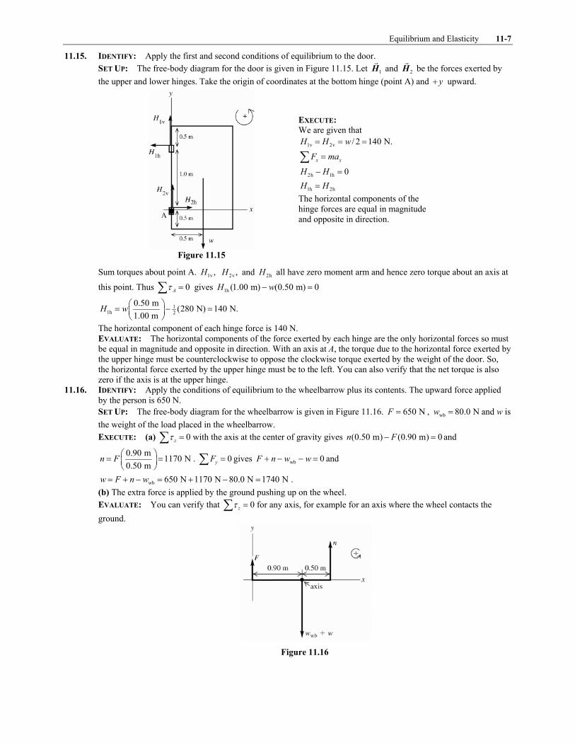
Equilibrium and Elasticity 11-7
11.15. IDENTIFY: Apply the first and second conditions of equilibrium to the door.
SET UP: The free-body diagram for the door is given in Figure 11.15. Let 1H
! and 2H
! be the forces exerted by
the upper and lower hinges. Take the origin of coordinates at the bottom hinge (point A) and y! upward.
EXECUTE: We are given that
1v 2v / 2 140 N.H H w" " "
x xF ma"+
2h 1h 0H H# "
1h 2hH H"
The horizontal components of the
hinge forces are equal in magnitude
and opposite in direction.
Figure 11.15
Sum torques about point A. 1v ,H 2v ,H and 2hH all have zero moment arm and hence zero torque about an axis at
this point. Thus 0A* "+ gives 1h (1.00 m) (0.50 m) 0H w# "
11h 2
0.50 m(280 N) 140 N.
1.00 mH w
$ %" # "& '( )
The horizontal component of each hinge force is 140 N.
EVALUATE: The horizontal components of the force exerted by each hinge are the only horizontal forces so must
be equal in magnitude and opposite in direction. With an axis at A, the torque due to the horizontal force exerted by
the upper hinge must be counterclockwise to oppose the clockwise torque exerted by the weight of the door. So,
the horizontal force exerted by the upper hinge must be to the left. You can also verify that the net torque is also
zero if the axis is at the upper hinge.
11.16. IDENTIFY: Apply the conditions of equilibrium to the wheelbarrow plus its contents. The upward force applied
by the person is 650 N.
SET UP: The free-body diagram for the wheelbarrow is given in Figure 11.16. 650 NF " , wb 80.0 Nw " and w is
the weight of the load placed in the wheelbarrow.
EXECUTE: (a) 0z* "+ with the axis at the center of gravity gives (0.50 m) (0.90 m) 0n F# " and
0.90 m1170 N
0.50 mn F
$ %" "& '( )
. 0yF "+ gives wb 0F n w w! # # " and
wb 650 N 1170 N 80.0 N 1740 Nw F n w" ! # " ! # " .
(b) The extra force is applied by the ground pushing up on the wheel.
EVALUATE: You can verify that 0z* "+ for any axis, for example for an axis where the wheel contacts the
ground.
Figure 11.16

11-8 Chapter 11
11.17. IDENTIFY: Apply the first and second conditions of equilibrium to Clea.
SET UP: Consider the forces on Clea. The free-body diagram is given in Figure 11.17
EXECUTE:
r 89 N,n " f 157 Nn "
r fn n w! " so 246 Nw "
Figure 11.17
0,z* "+ axis at rear feet
Let x be the distance from the rear feet to the center of gravity.
f (0.95 m) 0n xw# "
0.606 mx " from rear feet so 0.34 m from front feet.
EVALUATE: The normal force at her front feet is greater than at her rear feet, so her center of gravity is closer to
her front feet.
11.18. IDENTIFY: Apply the conditions for equilibrium to the crane.
SET UP: The free-body diagram for the crane is sketched in Figure 11.18. hF and vF are the components of the
force exerted by the axle. T!
pulls to the left so hF is to the right. T!
also pulls downward and the two weights are
downward, so vF is upward.
EXECUTE: (a) 0z* "+ gives c b([13 m]sin 25 ([7.0 m]cos55 ) ([16.0 m]cos55 0T w w# # "! ! ! .
4(11,000 N)([16.0 m]cos55 ) (15,000 N)([7.0 m]cos552.93 10 N
(13.0 m)sin 25T
!" " 2
! !"
!.
(b) 0xF "+ gives h cos30 0F T# "! and 4
h 2.54 10 NF " 2 .
0yF "+ gives v c bsin30 0F T w w# # # "! and 4
v 4.06 10 NF " 2 .
EVALUATE: 4
v
4
h
4.06 10 Ntan
2.54 10 N
F
F1
2" "
2and 581 " ! . The force exerted by the axle is not directed along the crane.
Figure 11.18
11.19. IDENTIFY: Apply the first and second conditions of equilibrium to the rod.
SET UP: The force diagram for the rod is given in Figure 11.19.
Figure 11.19

Equilibrium and Elasticity 11-9
EXECUTE: 0,z* "+ axis at right end of rod, counterclockwise torque is positive
1(240 N)(1.50 m) (90 N)(0.50 m) ( sin30.0 )(3.00 m) 0T! # , "
1
360 N m 45 N m270 N
1.50 mT
. ! ." "
x xF ma"+
2 1cos cos30 0T T1 # , " and 2 cos 234 NT 1 "
y yF ma"+
1 2sin30 sin 240 N 90 N 0T T 1, ! # # "
2 sin 330 N (270 N)sin30 195 NT 1 " # , "
Then 2
2
sin 195 N
cos 234 N
T
T
11" gives tan 0.83331 " and 401 " ,
And 2
195 N303 N.
sin 40T " "
,
EVALUATE: The monkey is closer to the right rope than to the left one, so the tension is larger in the right rope.
The horizontal components of the tensions must be equal in magnitude and opposite in direction. Since 2 1,T T3 the
rope on the right must be at a greater angle above the horizontal to have the same horizontal component as the
tension in the other rope.
11.20. IDENTIFY: Apply the first and second conditions for equilibrium to the beam.
SET UP: The free-body diagram for the beam is given in Figure 11.20.
EXECUTE: The cable is given as perpendicular to the beam, so the tension is found by taking torques about the
pivot point; (3.00 m) (1.00 kN)(2.00 m)cos25.0 (5.00 kN)(4.50 m)cos25.0T " , ! , , and 7.40 kNT " . The vertical
component of the force exerted on the beam by the pivot is the net weight minus the upward component of T,
6.00 kN cos25.0 0.17 kN.T# , " The horizontal force is sin 25.0 3.13 kN.T , "
EVALUATE: The vertical component of the tension is nearly the same magnitude as the total weight of the object
and the vertical component of the force exerted by the pivot is much less than its horizontal component.
Figure 11.20
11.21. (a) IDENTIFY and SET UP: Use Eq.(10.3) to calculate the torque (magnitude and direction) for each force and add
the torques as vectors. See Figure 11.21a.
EXECUTE:
1 1 1 (8.00 N)(3.00 m)Fl* " " !
1 24.0 N m* " ! .
2 2 2 (8.00 N)( 3.00 m)F l l* " # " # !
2 24.0 N m (8.00 N)l* " # . #
Figure 11.21a
1 2 24.0 N m 24.0 N m (8.00 N) (8.00 N)z l l* * *" ! " ! . # . # " #+
Want l that makes 6.40 N mz* " # .+ (net torque must be clockwise)
(8.00 N) 6.40 N ml# " # .
(6.40 N m)/8.00 N 0.800 ml " . "

11-10 Chapter 11
(b) 2 1* *3 since 2F has a larger moment arm; the net torque is clockwise.
(c) See Figure 11.21b.
1 1 1 (8.00 N)Fl l* " # " #
2 0* " since 2F
! is at the axis
Figure 11.21b
6.40 N mz* " # .+ gives (8.00 N) 6.40 N ml# " # .
0.800 m,l " same as in part (a).
EVALUATE: The force couple gives the same magnitude of torque for the pivot at any point.
11.22. IDENTIFY: 0l FY
A l
4"5
SET UP: 2 4 250.0 cm 50.0 10 mA #" " 2 .
EXECUTE: relaxed: 4
4 2 2
(0.200 m)(25.0 N)3.33 10 Pa
(50.0 10 m )(3.0 10 m)Y
# #" " 2
2 2
maximum tension: 5
4 2 2
(0.200 m)(500 N)6.67 10 Pa
(50.0 10 m )(3.0 10 m)Y
# #" " 2
2 2
EVALUATE: The muscle tissue is much more difficult to stretch when it is under maximum tension.
11.23. IDENTIFY and SET UP: Apply Eq.(11.10) and solve for A and then use 2A r6" to get the radius and 2d r" to
calculate the diameter.
EXECUTE: 0
l FY
A l
4"5
so 0
l FA
Y l
4"5
(A is the cross-section area of the wire)
For steel, 112.0 10 PaY " 2 (Table 11.1)
Thus 6 2
11 2
(2.00 m)(400 N)1.6 10 m .
(2.0 10 Pa)(0.25 10 m)A #
#" " 2
2 2
2 ,A r6" so 6 2 4/ 1.6 10 m / 7.1 10 mr A 6 6# #" " 2 " 2 32 1.4 10 m 1.4 mmd r #" " 2 "
EVALUATE: Steel wire of this diameter doesn�t stretch much; 0/ 0.12%.l l5 "
11.24. IDENTIFY: Apply Eq.(11.10).
SET UP: From Table 11.1, for steel, 112.0 10 PaY " 2 and for copper, 111.1 10 PaY " 2 . 2 4 2( / 4) 1.77 10 mA d6 #" " 2 . 4000 NF4 " for each rod.
EXECUTE: (a) The strain is 0
l Fl YA5 " . For steel 4
11 4 2
0
(4000N)1.1 10 .
(2.0 10 Pa)(1.77 10 m )
l
l
##
5" " 2
2 2 Similarly, the
strain for copper is 42.1 10 .#2
(b) Steel: 4 5(1.1 10 )(0.750 m) 8.3 10 m# #2 " 2 . Copper: 4 4(2.1 10 )(0.750 m) 1.6 10 m# #2 " 2 .
EVALUATE: Copper has a smaller Y and therefore a greater elongation.
11.25. IDENTIFY: 0l FY
A l
4"5
SET UP: 2 4 20.50 cm 0.50 10 mA #" " 2
EXECUTE: 11
4 2 2
(4.00 m)(5000 N)2.0 10 Pa
(0.50 10 m )(0.20 10 m)Y
# #" " 2
2 2
EVALUATE: Our result is the same as that given for steel in Table 11.1.
11.26. IDENTIFY: 0l FY
A l
4"5
SET UP: 2 3 2 5 2(3.5 10 m) 3.85 10 mA r6 6 # #" " 2 " 2 . The force applied to the end of the rope is the weight of the
climber: 2(65.0 kg)(9.80 m/s ) 637 NF4 " " .
EXECUTE: 8
5 2
(45.0 m)(637 N)6.77 10 Pa
(3.85 10 m )(1.10 m)Y
#" " 2
2
EVALUATE: Our result is a lot smaller than the values given in Table 11.1. An object made of rope material is
much easier to stretch than if the object were made of metal.
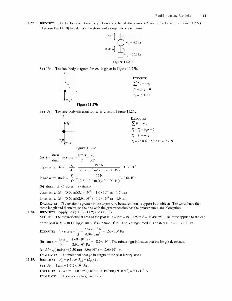
Equilibrium and Elasticity 11-11
11.27. IDENTIFY: Use the first condition of equilibrium to calculate the tensions 1T and 2T in the wires (Figure 11.27a).
Then use Eq.(11.10) to calculate the strain and elongation of each wire.
Figure 11.27a
SET UP: The free-body diagram for 2m is given in Figure 11.27b.
EXECUTE:
y yF ma"+
2 2 0T m g# "
2 98.0 NT "
Figure 11.27b
SET UP: The free-body-diagram for 1m is given in Figure 11.27c
EXECUTE:
y yF ma"+
1 2 1 0T T m g# # "
1 2 1T T m g" !
1 98.0 N 58.8 N 157 NT " ! "
Figure 11.27c
(a) stress
strainY " so
stressstrain
F
Y AY
4" "
upper wire: 31
7 2 11
157 Nstrain 3.1 10
(2.5 10 m )(2.0 10 Pa)
T
AY
##
" " " 22 2
lower wire: 32
7 2 11
98 Nstrain 2.0 10
(2.5 10 m )(2.0 10 Pa)
T
AY
##
" " " 22 2
(b) 0strain /l l" 5 so 0 (strain)l l5 "
upper wire: 3 3(0.50 m)(3.1 10 ) 1.6 10 m 1.6 mml # #5 " 2 " 2 "
lower wire: 3 3(0.50 m)(2.0 10 ) 1.0 10 m 1.0 mml # #5 " 2 " 2 "
EVALUATE: The tension is greater in the upper wire because it must support both objects. The wires have the
same length and diameter, so the one with the greater tension has the greater strain and elongation.
11.28. IDENTIFY: Apply Eqs.(11.8), (11.9) and (11.10).
SET UP: The cross-sectional area of the post is 2 2 2(0.125 m) 0.0491 mA r6 6" " " . The force applied to the end
of the post is 2 4(8000 kg)(9.80 m/s ) 7.84 10 NF4 " " 2 . The Young�s modulus of steel is 112.0 10 PaY " 2 .
EXECUTE: (a) 4
6
2
7.84 10 Nstress 1.60 10 Pa
0.0491 m
F
A
4 2" " " 2
(b) 6
6
11
stress 1.60 10 Pastrain 8.0 10
2.0 10 PaY
#2" " # " # 2
2. The minus sign indicates that the length decreases.
(c) 6 5
0(strain) (2.50 m)( 8.0 10 ) 2.0 10 ml l # #5 " " # 2 " # 2
EVALUATE: The fractional change in length of the post is very small.
11.29. IDENTIFY: F pA4 " , so net ( )F p A" 5 .
SET UP: 51 atm 1.013 10 Pa" 2 .
EXECUTE: 5 2 6(2.8 atm 1.0 atm)(1.013 10 Pa/atm)(50.0 m ) 9.1 10 N.# 2 " 2
EVALUATE: This is a very large net force.

11-12 Chapter 11
11.30. IDENTIFY: Apply Eq.(11.13).
SET UP: 0V pV
B
55 " # . p5 is positive when the pressure increases.
EXECUTE: (a) The volume would increase slightly.
(b) The volume change would be twice as great.
(c) The volume change is inversely proportional to the bulk modulus for a given pressure change, so the volume
change of the lead ingot would be four times that of the gold.
EVALUATE: For lead, 104.1 10 PaB " 2 , so /p B5 is very small and the fractional change in volume is very
small.
11.31. IDENTIFY: /p F A"
SET UP: 2 4 21 cm 1 10 m#" 2
EXECUTE: (a) 6
4 2
250 N 3.33 10 Pa.0.75 10 m# " 2
2
(b) 6 4 2(3.33 10 Pa)(2)(200 10 m ) 133 kN.#2 2 "
EVALUATE: The pressure in part (a) is over 30 times larger than normal atmospheric pressure.
11.32. IDENTIFY: Apply Eq.(11.13). Density /m V" .
SET UP: At the surface the pressure is 51.0 10 Pa2 , so 81.16 10 Pap5 " 2 . 3
0 1.00 mV " . At the surface
31.00 m of water has mass 31.03 10 kg2 .
EXECUTE: (a) 0( )p VB
V
5" #
5 gives
8 330
9
( ) (1.16 10 Pa)(1.00 m )0.0527 m
2.2 10 Pa
p VV
B
5 25 " # " # " #
2
(b) At this depth 31.03 10 kg2 of seawater has volume 3
0 0.9473 mV V! 5 " . The density is
33 3
3
1.03 10 kg1.09 10 kg/m
0.9473 m
2" 2 .
EVALUATE: The density is increased because the volume is compressed due to the increased pressure.
11.33. IDENTIFY and SET UP: Use Eqs.(11.13) and (11.14) to calculate B and k.
EXECUTE: 6 3
9
3
0
(3.6 10 Pa)(600 cm )4.8 10 Pa
/ ( 0.45 cm )
pB
V V
5 2" # " # " ! 2
5 #
9 10 11/ 1/ 4.8 10 Pa 2.1 10 Pak B # #" " 2 " 2
EVALUATE: k is the same as for glycerine (Table 11.2).
11.34. IDENTIFY: Apply Eq.(11.17).
SET UP: 59.0 10 NF " 2
". 2(0.100 m)(0.500 10 m)A #" 2 . 0.100 mh " . From Table 11.1, 107.5 10 PaS " 2 for
steel.
EXECUTE: (a) 5
|| 2
2 10
(9 10 N)Shear strain 2.4 10 .
[(0.100 m)(0.500 10 m)][7.5 10 Pa]
F
AS
##
2" " " 2
2 2
(b) Using Eq.(11.16), 3(Shear strain) (0.024)(0.100 m) 2.4 10 mx h #" . " " 2 .
EVALUATE: This very large force produces a small displacement; / 2.4%x h " .
11.35. IDENTIFY: The forces on the cube must balance. The deformation x is related to the force by F h
SA x
" ".
F F""
since F is applied parallel to the upper face.
SET UP: 2(0.0600 m)A " and 0.0600 mh " . Table 11.1 gives 104.4 10 PaS " 2 for copper and 100.6 10 Pa2 for
lead.
EXECUTE: (a) Since the horizontal forces balance, the glue exerts a force F in the opposite direction.
(b) 2 3 10
5(0.0600 m) (0.250 10 m)(4.4 10 Pa)6.6 10 N
0.0600 m
AxSF
h
#2 2" " " 2
(c) 5
2 10
(6.6 10 N)(0.0600 m)1.8 mm
(0.0600 m) (0.6 10 Pa)
Fhx
AS
2" " "
2
EVALUATE: Lead has a smaller S than copper, so the lead cube has a greater deformation than the copper cube.
11.36. IDENTIFY and SET UP: Use Eq.(11.17). Same material implies same S
EXECUTE: stress
strainS " so
/stressstrain
F A
S S" " "
and same forces implies same .F"

Equilibrium and Elasticity 11-13
For the smaller object, 1 1(strain) /F A S""
For the larger object, 2 2(strain) /F A S""
2 1 1
1 2 2
(strain)
(strain)
F A S A
A S F A
$ %$ %" "& '& '& '( )( )
"
"
Larger solid has triple each edge length, so 2 19 ,A A" and 2
1
(strain) 1
(strain) 9"
EVALUATE: The larger object has a smaller deformation.
11.37. IDENTIFY and SET UP: Use Eq.(11.8).
EXECUTE: 7
2 3 2
90.8 NTensile stress 3.41 10 Pa
(0.92 10 m)
F F
A r6 64 4
#" " " " 2
2
EVALUATE: A modest force produces a very large stress because the cross-sectional area is small.
11.38. IDENTIFY: The proportional limit and breaking stress are values of the stress, /F A4 . Use Eq.(11.10) to
calculate l5 .
SET UP: For steel, 1020 10 PaY " 2 . F w4 " .
EXECUTE: (a) 3 10 6 2 3(1.6 10 )(20 10 Pa)(5 10 m ) 1.60 10 N.w # #" 2 2 2 " 2
(b) 30 (1.6 10 )(4.0 m) 6.4 mmF l
lA Y
#4$ %5 " " 2 "& '( )
(c) 3 10 6 2 3(6.5 10 )(20 10 Pa)(5 10 m ) 6.5 10 N.# #2 2 2 " 2
EVALUATE: At the proportional limit, the fractional change in the length of the wire is 0.16%.
11.39. IDENTIFY: The elastic limit is a value of the stress, /F A4 . Apply m"+F a! !
to the elevator in order to find the
tension in the cable.
SET UP: 8 81
3(2.40 10 Pa) 0.80 10 Pa
F
A
4 " 2 " 2 . The free-body diagram for the elevator is given in Figure 11.39.
F4 is the tension in the cable.
EXECUTE: 8 4 2 8 4(0.80 10 Pa) (3.00 10 m )(0.80 10 Pa) 2.40 10 NF A #
4 " 2 " 2 2 " 2 . y yF ma"+ applied to the
elevator gives F mg ma4 # " and 4
2 22.40 10 N9.80 m/s 10.2 m/s
1200 kg
Fa g
m
4 2" # " # "
EVALUATE: The tension in the cable is about twice the weight of the elevator.
Figure 11.39
11.40. IDENTIFY: The breaking stress of the wire is the value of /F A4 at which the wire breaks.
SET UP: From Table 11.3, the breaking stress of brass is 84.7 10 Pa2 . The area A of the wire is related to its
diameter by 2 / 4A d6" .
EXECUTE: 7 2
8
350 N7.45 10 m , so 4 0.97 mm.
4.7 10 PaA d A 6#" " 2 " "
2
EVALUATE: The maximum force a wire can withstand without breaking is proportional to the square of its
diameter.

11-14 Chapter 11
11.41. IDENTIFY: Apply the conditions of equilibrium to the climber. For the minimum coefficient of friction the static
friction force has the value s sf n-" .
SET UP: The free-body diagram for the climber is given in Figure 11.41. sf and n are the vertical and horizontal
components of the force exerted by the cliff face on the climber. The moment arm for the force T is (1.4 m)cos10! .
EXECUTE: (a) 0z* "+ gives (1.4 m)cos10 (1.1 m)cos35.0 0T w# "! ! .
2(1.1 m)cos35.0(82.0 kg)(9.80 m/s ) 525 N
(1.4 m)cos10T " "
!
!
(b) 0xF "+ gives sin 25.0 222 Nn T" "! . 0yF "+ gives s cos25 0f T w! # "! and
2
s (82.0 kg)(9.80 m/s ) (525 N)cos25 328 Nf " # "! .
(c) ss
328 N1.48
222 N
f
n- " " "
EVALUATE: To achieve this large value of s- the climber must wear special rough-soled shoes.
Figure 11.41
11.42. IDENTIFY: Apply 0z* "+ to the bridge.
SET UP: Let the axis of rotation be at the left end of the bridge and let counterclockwise torques be positive.
EXECUTE: If Lancelot were at the end of the bridge, the tension in the cable would be (from taking torques about
the hinge of the bridge) obtained from 2 2(12.0 N) (600 kg)(9.80 m s )(12.0 m) (200 kg)(9.80 m s )(6.0 m)T " ! ,
so 6860 NT " . This exceeds the maximum tension that the cable can have, so Lancelot is going into the drink. To
find the distance x Lancelot can ride, replace the 12.0 m multiplying Lancelot�s weight by x and the tension 3
max by 5.80 10 NT T " 2 and solve for x;
3 2
2
(5.80 10 N)(12.0 m) (200 kg)(9.80 m s )(6.0 m)9.84 m.
(600 kg)(9.80 m s )x
2 #" "
EVALUATE: Before Lancelot goes onto the bridge, the tension in the supporting cable is 2(6.0 m)(200 kg)(9.80 m/s )
9800 N12.0 m
T " " , well below the breaking strength of the cable. As he moves along the
bridge, the increase in tension is proportional to x, the distance he has moved along the bridge.
11.43. IDENTIFY: For the airplane to remain in level flight, both 0 and 0y zF *+ " + " .
SET UP: The free-body diagram for the airplane is given in Figure 11.43. Let y! be upward.
EXECUTE: tail wing 0F W F# # ! " . Taking the counterclockwise direction as positive, and taking torques about the
point where the tail force acts, wing(3.66 m)(6700 N) (3.36 m) 0.F# ! " This gives wing 7300 N(up)F " and
tail 7300 N 6700 N 600 N(down).F " # "

Equilibrium and Elasticity 11-15
EVALUATE: We assumed that the wing force was upward and the tail force was downward. When we solved for
these forces we obtained positive values for them, which confirms that they do have these directions. Note that the
rear stabilizer provides a downward force. It does not hold up the tail of the aircraft, but serves to counter the
torque produced by the wing. Thus balance, along with weight, is a crucial factor in airplane loading.
Figure 11.43
11.44. IDENTIFY: Apply the first and second conditions of equilibrium to the truck.
SET UP: The weight on the front wheels is fn , the normal force exerted by the ground on the front wheels. The
weight on the rear wheels is rn , the normal force exerted by the ground on the rear wheels. When the front wheels
come off the ground, f 0n 7 . The free-body diagram for the truck without the box is given in Figure 11.44a and
with the box in Figure 11.44b. The center of gravity of the truck, without the box, is a distance x from the rear
wheels.
EXECUTE: 0yF "+ in Fig.11.44a gives r f 8820 N 10,780 N 19,600 Nw n n" ! " ! "
0* "+ in Fig.11.44a, with the axis at the rear wheels and counterclockwise torques positive, gives
f (3.00 m) 0n wx# " and f (3.00 m) 10,780 N(3.00 m) 1.65 m
19,600 N
nx
w
$ %" " "& '
( ).
(a) 0* "+ in Fig.11.44b, with the axis at the rear wheels and counterclockwise torques positive, gives
box f(1.00 m) (3.00 m) (1.65 m) 0w n w! # " .
f
(3600 N)(1.00 m) (19,600 N)(1.65 m)9,580 N
3.00 mn
# !" "
0yF "+ gives r f boxn n w w! " ! and r 3600 N 19,600 N 9580 N 13,620 Nn " ! # " . There is 9,580 N on the
front wheels and 13,620 N on the rear wheels.
(b) f 0n 7 . 0* "+ gives box (1.00 m) (1.65 m) 0w w# " and 4
box 1.65 3.23 10 Nw w" " 2 .
EVALUATE: Placing the box on the tailgate in part (b) reduces the normal force exerted at the front wheels.
Figure 11.44a, b
11.45. IDENTIFY: In each case, to achieve balance the center of gravity of the system must be at the fulcrum. Use
Eq.(11.3) to locate cmx , with im replaced by iw .
SET UP: Let the origin be at the left-hand end of the rod and take the x! axis to lie along the rod. Let
1 255 Nw " (the rod) so 1 1.00 mx " , let 2 225 Nw " so 2 2.00 mx " and let 3w W" . In part (a) 3 0.500 mx " and
in part (b) 3 0.750 mx " .
EXECUTE: (a) cm 1.25 mx " . 1 1 2 2 3 3cm
1 2 3
w x w x w xx
w w w
! !"
! !gives 1 2 cm 1 1 2 2
3
3 cm
( )w w x w x w xw
x x
! # #"
#and
(480 N)(1.25 m) (255 N)(1.00 m) (225 N)(2.00 m)140 N
0.500 m 1.25 mW
# #" "
#.
(b) Now 3 140 Nw W" " and 3 0.750 mx " .
cm
(255 N)(1.00 m) (225 N)(2.00 m) (140 N)(0.750 m)1.31 m
255 N 225 N 140 Nx
! !" "
! !. W must be moved
1.31 m 1.25 m 6 cm# " to the right.
EVALUATE: Moving W to the right means cmx for the system moves to the right.

11-16 Chapter 11
11.46. IDENTIFY: The center of gravity of the object must have the same x coordinate as the hook. Use Eq.(11.3) for
cmx . The mass of a segment is proportional to its length. Define 8 to be the mass per unit length, so i im l8" ,
where il is the length of a piece that has mass im .
SET UP: Use coordinates with the origin at the right-hand edge of the object and x! to the left. cmx L" . The
mass of each piece can be taken at its center of gravity, which is at its geometrical center. Let 1 be the horizontal
piece of length L, 2 be the vertical piece of length L and 3 be the horizontal piece with length x.
EXECUTE: 1 1 2 2 3 3cm
1 2 3
m x m x m xx
m m m
! !"
! !gives
( / 2) ( / 2)L L x xL
L L x
8 88 8 8
!"
! !. 8 divides out and the equation reduces to
2 22 3 0x xL L# # " . 1
2(2 4 )x L L" 9 . x must be positive, so 3x L" .
EVALUATE: cmx L" is equivalent to saying that the net torque is zero for an axis at the hook.
11.47. IDENTIFY: Apply the conditions of equilibrium to the horizontal beam. Since the two wires are symmetrically
placed on either side of the middle of the sign, their tensions are equal and are each equal to w / 2 137 NT mg" " .
SET UP: The free-body diagram for the beam is given in Figure 11.47. vF and hF are the horizontal and vertical
forces exerted by the hinge on the sign. Since the cable is 2.00 m long and the beam is 1.50 m long,
1.50 mcos
2.00 m1 " and 41.41 " ! . The tension cT in the cable has been replaced by its horizontal and vertical
components.
EXECUTE: (a) 0z* "+ gives c beam w w(sin 41.4 )(1.50 m) (0.750 m) (1.50 m) (0.60 m) 0T w T T# # # "! .
2
c
(18.0 kg)(9.80 m/s )(0.750 m) (137 N)(1.50 m 0.60 m)423 N
(1.50 m)(sin 41.4 )T
! !" "
!.
(b) 0yF "+ gives v c beam wsin 41.4 2 0F T w T! # # "! and
2
v w beam c2 sin 41.4 2(137 N) (18.0 kg)(9.80 m/s ) (423 N)(sin 41.4 ) 171 NF T w T" ! # " ! # "! ! . The hinge must be
able to supply a vertical force of 171 N.
EVALUATE: The force from the two wires could be replaced by the weight of the sign acting at a point 0.60 m to
the left of the right-hand edge of the sign.
Figure 11.47
11.48. IDENTIFY: Apply 0z* "+ to the hammer.
SET UP: Take the axis of rotation to be at point A.
EXECUTE: The force 1F
! is directed along the length of the nail, and so has a moment arm of (0.800 m)sin 60, .
The moment arm of 2F
! is 0.300 m, so
2 1
(0.0800 m)sin 60(500 N)(0.231) 116 N.
(0.300 m)F F
," " "
EVALUATE: The force 2F that must be applied to the hammer handle is much less than the force that the hammer
applies to the nail, because of the large difference in the lengths of the moment arms.
11.49. IDENTIFY: Apply the first and second conditions of equilibrium to the bar.
SET UP: The free-body diagram for the bar is given in Figure 11.49. n is the normal force exerted on the bar by
the surface. There is no friction force at this surface. hH and vH are the components of the force exerted on the

Equilibrium and Elasticity 11-17
bar by the hinge. The components of the force of the bar on the hinge will be equal in magnitude and opposite in
direction.
EXECUTE:
x xF ma"+
h 120 NF H" "
y yF ma"+
v 0n H# "
v ,H n" but we don�t know
either of these forces.
Figure 11.49
0B* "+ gives (4.00 m) (3.00 m) 0F n# "
4
3(4.00 m/3.00 m) (120 N) 160 Nn F" " " and then v 160 NH "
Force of bar on hinge:
horizontal component 120 N, to right
vertical component 160 N, upward
EVALUATE: h v/ 120/160 3.00/ 4.00,H H " " so the force the hinge exerts on the bar is directed along the bar. n!
and F!
have zero torque about point A, so the line of action of the hinge force H!
must pass through this point
also if the net torque is to be zero.
11.50. IDENTIFY: Apply 0z* "+ to the piece of art.
SET UP: The free-body diagram for the piece of art is given in Figure 11.50.
EXECUTE: 0z* "+ gives (1.25 m) (1.02 m) 0BT w# " . 1.02 m
(358 N) 292 N1.25 m
BT$ %" "& '( )
. 0yF "+ gives
0A BT T w! # " and 358 N 292 N 66 NA BT w T" # " # " .
EVALUATE: If we consider the sum of torques about the center of gravity of the piece of art, AT has a larger
moment arm than BT , and this is why A BT T: .
Figure 11.50
11.51. IDENTIFY: Apply the conditions of equilibrium to the beam.
SET UP: The free-body diagram for the beam is given in Figure 11.51. Let T; and T1 be the tension in the two
cables. Each tension has been replaced by its horizontal and vertical components.
EXECUTE: (a) The center of gravity of the beam is a distance / 2L from each end and 0z* "+ with the axis at
the center of gravity of the beam gives sin ( / 2) sin ( / 2) 0T L T L; 1; 1# ! " . sin sinT T; 1; 1" . 0xF "+ gives
cos cosT T; 1; 1" . Dividing the first equation by the second gives tan tan; 1" and ; 1" . Then the equations also
say T T; 1" .
(b) The center of gravity of the beam is a distance 3 / 4L from the left-hand end so a distance / 4L from the right-
hand end. 0z* "+ with the axis at the center of gravity of the beam gives sin (3 / 2) sin ( / 2) 0T L T L; 1; 1# ! " and
3 sin sinT T; 1; 1" . 0xF "+ gives cos cosT T; 1; 1" . Dividing the first equation by the second gives
3tan tan; 1" .

11-18 Chapter 11
EVALUATE: 3tan tan; 1" requires 1 ;3 . The cable closest to the center of gravity must be closer to the vertical
direction. cos
cosT T1 ;
;1
$ %" & '( )
and 1 ;3 means the tension is greater in the wire that is closest to the center of gravity.
Figure 11.51
11.52. IDENTIFY: Apply the first and second conditions for equilibrium to the bridge.
SET UP: Find torques about the hinge. Use L as the length of the bridge and T Band w w for the weights of the
truck and the raised section of the bridge. Take y! to be upward and x! to be to the right.
EXECUTE: (a) / 0 / 03 1T B4 2
sin70 cos30 cos30TL w L w L, " , ! , , so
/ 0 23 1T B 54 2
(9.80 m s )cos302.57 10 N.
sin 70
m mT
! ," " 2
,
(b) Horizontal: / 0 5cos 70 30 1 97 10 NT ., # , " 2 (to the right). Vertical: 5
T B sin 40 2.46 10 Nw w T! # , " 2 (upward).
EVALUATE: If ; is the angle of the hinge force above the horizontal, 5
5
2.46 10 Ntan
1.97 10 N;
2"
2 and 51.3; " ! . The
hinge force is not directed along the bridge.
11.53. IDENTIFY: Apply the conditions of equilibrium to the cylinder.
SET UP: The free-body diagram for the cylinder is given in Figure 11.53. The center of gravity of the cylinder is
at its geometrical center. The cylinder has radius R.
EXECUTE: (a) T produces a clockwise torque about the center of gravity so there must be a friction force, that
produces a counterclockwise torque about this axis.
(b) Applying 0z* "+ to an axis at the center of gravity gives 0TR fR# ! " and T f" . 0z* "+ applied to an
axis at the point of contact between the cylinder and the ramp gives (2 ) sin 0T R MgR 1# ! " . ( / 2)sinT Mg 1" .
EVALUATE: We can show that 0xF "+ and 0yF "+ , for x and y axes parallel and perpendicular to the ramp,
or for x and y axes that are horizontal and vertical.
Figure 11.53

Equilibrium and Elasticity 11-19
11.54. IDENTIFY: Apply the first and second conditions of equilibrium to the ladder.
SET UP: Take torques about the pivot. Let y! be upward.
EXECUTE: (a) The force VF that the ground exerts on the ladder is given to be vertical, so 0z* "+
gives V (6.0 m)sin (250 N)(4.0 m)sin (750 N)(1.50 m)sinF " " "" ! , so V 354 N.F "
(b) There are no other horizontal forces on the ladder, so the horizontal pivot force is zero. The vertical force that
the pivot exerts on the ladder must be (750 N) (250 N) (354 N) 646 N,! # " up, so the ladder exerts a downward
force of 646 N on the pivot.
(c) The results in parts (a) and (b) are independent of ".
EVALUATE: All the forces on the ladder are vertical, so all the moment arms are vertical and are proportional to
sin1 . Therefore, sin1 divides out of the torque equations and the results are independent of 1 .
11.55. IDENTIFY: Apply the first and second conditions for equilibrium to the strut.
SET UP: Denote the length of the strut by L .
EXECUTE: (a) and .V mg w H T" ! " To find the tension, take torques about the pivot point.
2 2sin cos cos
3 3 6
LT L " w L " mg "$ % $ % $ %" !& ' & ' & '( ) ( ) ( )
and cot4
mgT w "
$ %" !& '( )
.
(b) Solving the above for w , and using the maximum tension for ,T
2 tan (700 N) tan55 0 (5.0 kg)(9.80 m s ) 951 N.4
mgw T " ." # " , # "
(c) Solving the expression obtained in part (a) for tan 1 and letting 0, tan 0.700, so 4 00 .4
mg# " " .
T7 " " " ,
EVALUATE: As the strut becomes closer to the horizontal, the moment arm for the horizontal tension force
approaches zero and the tension approaches infinity.
11.56. IDENTIFY: Apply the first and second conditions of equilibrium to each rod.
SET UP: Apply 0yF "+ with y! upward and apply 0* "+ with the pivot at the point of suspension for each
rod.
EXECUTE: (a) The free-body diagram for each rod is given in Figure 11.56.
(b) 0* "+ for the lower rod: (6.0 N)(4.0 cm) (8.0 cm)Aw" and 3.0 NAw " .
0yF "+ for the lower rod: 3 6.0 N 9.0 NAS w" ! "
0* "+ for the middle rod: 3(3.0 cm) (5.0 cm)Bw S" and 5.0
(9.0 N) 15.0 N3.0
Bw$ %" "& '( )
.
0yF "+ for the middle rod: 2 39.0 N 24.0 NS S" ! "
0* "+ for the upper rod: 2(2.0 cm) (6.0 cm)CS w" and 2.0
(24.0 N) 8.0 N6.0
Cw$ %" "& '( )
.
0yF "+ for the upper rod: 1 2 32.0 NCS S w" ! " .
In summary, 3.0 NAw " , 15.0 NBw " , 8.0 NCw " . 1 32.0 NS " , 2 24.0 NS " , 3 9.0 NS " .
(c) The center of gravity of the entire mobile must lie along a vertical line that passes through the point where 1S is
located.
EVALUATE: For the mobile as a whole the vertical forces must balance, so 1 6.0 NA B CS w w w" ! ! ! .
Figure 11.56

11-20 Chapter 11
11.57. IDENTIFY: Apply 0z* "+ to the beam.
SET UP: The free-body diagram for the beam is given in Figure 11.57.
EXECUTE: 0, axis at hingez*< " , gives (6.0 m)(sin 40 ) (3.75 m)(cos30 ) 0T w, # , " and 7600 NT " .
EVALUATE: The tension in the cable is less than the weight of the beam. sin 40T ! is the component of T that is
perpendicular to the beam.
Figure 11.57
11.58. IDENTIFY: Apply the first and second conditions of equilibrium to the drawbridge.
SET UP: The free-body diagram for the drawbridge is given in Figure 11.58. vH and hH are the components of
the force the hinge exerts on the bridge.
EXECUTE: (a) 0z* "+ with the axis at the hinge gives (7.0 m)(cos37 ) (3.5 m)(sin37 ) 0w T# ! "! ! and
5cos37 (45,000 N)2 1.19 10 N
sin37 tan37T w" " " 2
!
! !
(b) 0xF "+ gives 5
h 1.19 10 NH T" " 2 . 0yF "+ gives 4
v 4.50 10 NH w" " 2 .
2 2 5
h v 1.27 10 NH H H" ! " 2 . v
h
tanH
H1 " and 20.71 " ! . The hinge force has magnitude 51.27 10 N 2 and is
directed at 20.7! above the horizontal.
EVALUATE: The hinge force is not directed along the bridge. If it were, it would have zero torque for an axis at
the center of gravity of the bridge and for that axis the tension in the cable would produce a single, unbalanced
torque.
Figure 11.58
11.59. IDENTIFY: Apply the first and second conditions of equilibrium to the beam.
SET UP: The free-body diagram for the beam is given in Figure 11.59.
Figure 11.59

Equilibrium and Elasticity 11-21
EXECUTE: (a) 0,z* "+ axis at lower end of beam
Let the length of the beam be L.
(sin 20 ) cos40 02
LT L mg
$ %, " # , "& '( )
12
cos402700 N
sin 20
mgT
," "
,
(b) Take y! upward.
0yF "+ gives sin60 0n w T# ! , " so 73.6 Nn "
0xF "+ gives s cos60 1372 Nf T" , "
s s ,f n-" ss
1372 N19
73.6 N
f
n- " " "
EVALUATE: The floor must be very rough for the beam not to slip. The friction force exerted by the floor is to
the left because T has a component that pulls the beam to the right.
11.60. IDENTIFY: Apply 0z* "+ to the beam.
SET UP: The center of mass of the beam is 1.0 m from the suspension point.
EXECUTE: (a) Taking torques about the suspension point,
(4.00 m)sin30 (140.0 N)(1.00 m)sin30 (100 N)(2.00 m)sin30w ! "! ! ! . The common factor of sin30! divides out,
from which 15.0 N.w "
(b) In this case, a common factor of sin 45!would be factored out, and the result would be the same.
EVALUATE: All the forces are vertical, so the moments are all horizontal and all contain the factor sin1 , where
1 is the angle the beam makes with the horizontal.
11.61. IDENTIFY: Apply 0z* "+ to the flagpole.
SET UP: The free-body diagram for the flagpole is given in Figure 11.61. Let clockwise torques be positive. 1 is
the angle the cable makes with the horizontal pole.
EXECUTE: (a) Taking torques about the hinged end of the pole
(200 N)(2.50 m) (600 N)(5.00 m) (5.00 m) 0yT! # " . 700 NyT " . The x-component of the tension is then
2 2(1000 N) (700 N) 714 NxT " # " . tan5.00 m
y
x
Th
T1 " " . The height above the pole that the wire must be
attached is 700(5.00 m) 4.90 m714
" .
(b) The y-component of the tension remains 700 N. Now 4.40 m
tan5.00 m
1 " and 41.351 " ! , so
700 N1060 N
sin sin 41.35
yTT
1" " "
!, an increase of 60 N.
EVALUATE: As the wire is fastened closer to the hinged end of the pole, the moment arm for T decreases and T
must increase to produce the same torque about that end.
Figure 11.61
11.62. IDENTIFY: Apply 0"+F!
to each object, including the point where D, C and B are joined. Apply 0z* "+ to
the rod.
SET UP: To find and ,C DT T use a coordinate system with axes parallel to the cords.
EXECUTE: A and B are straightforward, the tensions being the weights suspended: 2(0.0360 kg)(9.80 m/s ) 0.353 NA$ " " and 2(0.0240 kg 0.0360 kg)(9.80 m s ) 0.588 NBT " ! " . Applying
0xF "+ and 0yF "+ to the point where the cords are joined, cos36.9 0.470 NC BT T" , " and
cos53.1 0.353 ND BT T" , " . To find ,ET take torques about the point where string F is attached.

11-22 Chapter 11
2(1.00 m) sin36.9 (0.800 m) sin53.1 (0.200 m) (0 120 kg)(9 80 m s )(0 500 m)E D CT T T . . ." , ! , ! and 0.833 N.ET "
FT may be found similarly, or from the fact that E FT T! must be the total weight of the ornament.
2(0.180kg)(9.80m s ) 1.76 N, from which 0.931 N.FT" "
EVALUATE: The vertical line through the spheres is closer to F than to E, so we expect F ET T3 , and this is
indeed the case.
11.63. IDENTIFY: Apply the equilibrium conditions to the plate. sinFr* ;" .
SET UP: The free-body diagram for the plate is sketched in Figure 11.63. For the force T (tension in the cable),
2 2sin sinT Tr T h d* ; ;" " ! .
EXECUTE: (a) 0z* "+ gives 2 2 sin 02
dT h d W;! # " . T is least for 90; " ! , and in that case tan
h
d1 " so
1tanh
d1 # $ %" & '
( ). Then
2 22
dT W
h d"
!.
(b) 0xF "+ gives h 2 22 2 2 2sin
2( )2
Wd h WhdF T
h dh d h d1
$ %" " "& '
!! !( ). 0yF "+ gives v cos 0F T W1! # " and
2 2 2
v 2 2 2 22 2 2 2
21
2( ) 2( )2
Wd d d h dF W W W
h d h dh d h d
$ %$ % $ % !" # " # "& '& ' & '
! !! ! ( )( )( )
EVALUATE: The angle 8 that the net force exerted by the hinge makes with the horizontal is given by 2 2 2 2 2 2
v
2 2
h
(2 ) 2( ) 2tan
2( )
F W h d h d h d
F h d Whd hd8
! ! !" " "
!. This force does not lie along the diagonal of the plate.
Figure 11.63
11.64. IDENTIFY: Apply Eq.(11.10) and the relation 0 0/ /w w l l=5 " # 5 that is given in the problem.
SET UP: The steel rod in Example 11.5 has 4
0/ 9.0 10l l #5 " 2 . For nickel, 112.1 10 PaY " 2 . The width 0w is
0 4 /w A 6" .
EXECUTE: (a) 4 4 2
0 ( ) (0.23)(9.0 10 ) 4(0.30 10 m ) 1.3 m.w % l l w !6# #5 " # 5 " # 2 2 "
(b) 1
l w
F AY AYl % w
4
5 5" " and
11 2 2 36
2
(2.1 10 Pa) ( (2.0 10 m) ) 0.10 10 m3.1 10 N
0.42 2.0 10 m
&F
# #
4 #
2 2 2" " 2
2.
EVALUATE: For nickel and steel, 1= : and the fractional change in width is less than the fractional change in length.
11.65. IDENTIFY: Apply the equilibrium conditions to the crate. When the crate is on the verge of tipping it touches the
floor only at its lower left-hand corner and the normal force acts at this point. The minimum coefficient of static
friction is given by the equation s sf n-" .
SET UP: The free-body diagram for the crate when it is ready to tip is given in Figure 11.65.
EXECUTE: (a) 0z* "+ gives (1.50 m)sin53.0 (1.10 m) 0P w# "! . 31.10 m1.15 10 N
[1.50 m][sin53.0 ]P w
$ %" " 2& '
( )!
(b) 0yF "+ gives cos53.0 0n w P# # "! . 3 3cos53.0 1250 N (1.15 10 N)cos53 1.94 10 Nn w P" ! " ! 2 " 2! !
(c) 0xF "+ gives 3
s sin53.0 (1.15 10 N)sin53.0 918 Nf P" " 2 "! ! .
(d) ss 3
918 N0.473
1.94 10 N
f
n- " " "
2

Equilibrium and Elasticity 11-23
EVALUATE: The normal force is greater than the weight because P has a downward component.
Figure 11.65
11.66. IDENTIFY: Apply 0z* "+ to the meter stick.
SET UP: The wall exerts an upward static friction force f and a horizontal normal force n on the stick. Denote the
length of the stick by l. sf n-" .
EXECUTE: (a) Taking torques about the right end of the stick, the friction force is half the weight of the
stick, / 2f w" . Taking torques about the point where the cord is attached to the wall (the tension in the cord and
the friction force exert no torque about this point), and noting that the moment arm of the normal force is tanl 1 ,
tan / 2 Then, ( / ) tan 0.40, so arctan (0.40) 22 .n w f n 1 1 1" . " : : " ,
(b) Taking torques as in part (a), ( ) and n tan .2 2
l lfl w w l x l " w wx" ! # " ! In terms of the coefficient of friction
s ,- s
/ 2 ( ) 3 2tan tan .
/ 2 2
f l l x l x" "
n l x l x-
! # #3 " "
! ! Solving for x, s
s
3tan30 2 cm.
2 tan
l " !x .
! "
#3 "
!
(c) In the above expression, setting s10 cm and solving for givesx -" s
(3 20 ) tan0.625.
1 20
l "!
l
#3 "
!
EVALUATE: For 151 " ! and without the block suspended from the stick, a value of s 0.268- > is required to
prevent slipping. Hanging the block from the stick increases the value of s- that is required.
11.67. IDENTIFY: Apply the first and second conditions of equilibrium to the crate.
SET UP: The free-body diagram for the crate is given in Figure 11.67.
(0.375 m)cos45wl " ,
2 (1.25 m)cos45l " ,
Let 1F
! and 2F
! be the vertical
forces exerted by you and your
friend. Take the origin at the
lower left-hand corner of the
crate (point A).
Figure 11.67

11-24 Chapter 11
EXECUTE: y yF ma"+ gives 1 2 0F F w! # "
2
1 2 (200 kg)(9.80 m/s ) 1960 NF F w! " " "
0A* "+ gives 2 2 0wF l wl# "
2
2
0.375 mcos451960 N 590 N
1.25 mcos45
wlF wl
$ % ,$ %" " "& ' & ',( )( )
Then 1 2 1960 N 590 N 1370 N.F w F" # " # "
EVALUATE: The person below (you) applies a force of 1370 N. The person above (your friend) applies a force of
590 N. It is better to be the person above. As the sketch shows, the moment arm for 1F
! is less than for 2 ,F
! so must
have 1 2F F3 to compensate.
11.68. IDENTIFY: Apply the first and second conditions for equilibrium to the forearm.
SET UP: The free-body diagram is given in Figure 11.68a, and when holding the weight in Figure 11.68b. Let
y! be upward.
EXECUTE: (a) Elbow 0*< " gives B(3.80 cm) (15.0 N)(15.0 cm)F " and B 59.2 NF " .
(b) 0E*< " gives B(3.80 cm) (15.0 N)(15.0 cm) (80.0 N)(33.0 cm)F " ! and B 754 NF " . The biceps force has a
short lever arm, so it must be large to balance the torques.
(c) 0yF< " gives E B 15.0 N 80.0 N 0F F# ! # # " and E 754N 15.0 N 80.0 N 659 NF " # # " .
EVALUATE: (d) The biceps muscle acts perpendicular to the forearm, so its lever arm stays the same, but those of
the other two forces decrease as the arm is raised. Therefore the tension in the biceps muscle decreases.
Figure 11.68a, b
11.69. IDENTIFY: Apply 0z* "+ to the forearm.
SET UP: The free-body diagram for the forearm is given in Fig. 11.10 in the textbook.
EXECUTE: (a) 0, axis at elbowz*< " gives / 0sin 0wL T " D# " . 2 2 2 2
sin so h hD
" w Th D L h D
" "! !
.
max max2 2
hDw T
L h D"
!.
(b) 2
max max
2 22 21 ; the derivative is positive
dw T h D
dD h DL h D
$ %" #& '
!! ( )
EVALUATE: (c) The result of part (b) shows that maxw increases when D increases, since the derivative is positive.
maxw is larger for a chimp since D is larger.
11.70. IDENTIFY: Apply the first and second conditions for equilibrium to the table.
SET UP: Label the legs as shown in Figure 11.70a. Legs A and C are 3.6 m apart. Let the weight be placed closest
to legs C and D. By symmetry, A B" and C D" . Redraw the table as viewed from the AC side. The free-body
diagram in this view is given in Figure 11.70b.
EXECUTE: (about right end) 0z' "+ gives / 0 / 02 (3.6 m) 90.0 N (1.8 m) 1500 N (0.50 m)A " ! and
130 NA B" " . 0yF "+ gives 1590 NA B C D! ! ! " . Using 130 NA B" " and C D" gives 670 NC D" " .
By Newton�s third law of motion, the forces A, B, C, and D on the table are the same magnitude as the forces the
table exerts on the floor.

Equilibrium and Elasticity 11-25
EVALUATE: As expected, the legs closest to the 1500 N weight exert a greater force on the floor.
Figure 11.70a, b
11.71. IDENTIFY: Apply 0z* "+ first to the roof and then to one wall.
(a) SET UP: Consider the forces on the roof; see Figure 11.71a.
V and H are the vertical
and horizontal forces each
wall exerts on the roof.
20,000 Nw " is the total
weight of the roof.
2V w" so / 2V w"
Figure 11.71a
Apply 0z* "+ to one half of the roof, with the axis along the line where the two halves join. Let each half have
length L.
EXECUTE: ( / 2)( / 2)(cos35.0 ) sin35.0 cos35 0w L HL VL, ! , # , "
L divides out, and use / 2V w" 1
4sin35.0 cos35.0H w, " ,
7140 N4tan35.0
wH " "
,
EVALUATE: By Newton�s 3rd law, the roof exerts a horizontal, outward force on the wall. For torque about an
axis at the lower end of the wall, at the ground, this force has a larger moment arm and hence larger torque the
taller the walls.
(b) SET UP: The force diagram for one wall is given in Figure 11.71b.
Consider the torques
on this wall.
Figure 11.71b
H is the horizontal force exerted by the roof, as considered in part (a). B is the horizontal force exerted by the
buttress. Now the angle is 40 ,, so 5959 N4tan 40
wH " "
,
EXECUTE: 0,z* "+ axis at the ground
(40 m) (30 m) 0H B# " and 7900 N.B "
EVALUATE: The horizontal force exerted by the roof is larger as the roof becomes more horizontal, since for
torques applied to the roof the moment arm for H decreases. The force B required from the buttress is less the
higher up on the wall this force is applied.
11.72. IDENTIFY: Apply 0z* "+ to the wheel.
SET UP: Take torques about the upper corner of the curb.
EXECUTE: The force F!
acts at a perpendicular distance R h# and the weight acts at a perpendicular distance
/ 022 22 .R R h Rh h# # " # Setting the torques equal for the minimum necessary force, 22
.Rh h
F mgR h
#"
#

11-26 Chapter 11
(b) The torque due to gravity is the same, but the forceF!
acts at a perpendicular distance 2 ,R h# so the minimum
force is ( ) 2 /(2 ).mg Rh hv R h# #
EVALUATE: (c) Less force is required when the force is applied at the top of the wheel, since in this case F#
has a
larger moment arm.
11.73. IDENTIFY: Apply the first and second conditions of equilibrium to the gate.
SET UP: The free-body diagram for the gate is given in Figure 11.73.
Figure 11.73
Use coordinates with the origin at B. Let AH
! and BH
! be the forces exerted by the hinges at A and B. The problem
states that AH
! has no horizontal component. Replace the tension T
! by its horizontal and vertical components.
EXECUTE: (a) 0B* "+ gives ( sin30.0 )(4.00 m) ( cos30.0 )(2.00 m) (2.00 m) 0T T w! , ! , # "
(2sin30.0 cos30.0 )T w, ! , "
500 N268 N
2sin30.0 cos30.0 2sin30.0 cos30.0
wT " " "
, ! , , ! ,
(b) x xF ma"+ says h cos30.0 0BH T# , "
h cos30.0 (268 N)cos30.0 232 NBH T" , " , "
(c) y yF ma"+ says v v sin30.0 0A BH H T w! ! , # "
v v sin30.0 500 N (268 N)sin30.0 366 NA BH H w T! " # , " # , "
EVALUATE: T has a horizontal component to the left so hBH must be to the right, as these are the only two
horizontal forces. Note that we cannot determine vAH and vBH separately, only their sum.
11.74. IDENTIFY: Use Eq.(11.3) to locate the x-coordinate of the center of gravity of the block combinations.
SET UP: The center of mass and the center of gravity are the same point. For two identical blocks, the center of
gravity is midway between the center of the two blocks.
EXECUTE: (a) The center of gravity of top block can be as far out as the edge of the lower block. The center of
gravity of this combination is then 3 4L to the left of the right edge of the upper block, so the overhang is 3 4.L
(b) Take the two-block combination from part (a), and place it on top of the third block such that the overhang of
3 4L is from the right edge of the third block; that is, the center of gravity of the first two blocks is above the right
edge of the third block. The center of mass of the three-block combination, measured from the right end of the
bottom block, is 6L# and so the largest possible overhang is (3 4) ( 6) 11 12.L L L! " Similarly, placing this
three-block combination with its center of gravity over the right edge of the fourth block allows an extra overhang
of 8,L for a total of 25 24.L
(c) As the result of part (b) shows, with only four blocks, the overhang can be larger than the length of a single
block.
EVALUATE: The sequence of maximum overhangs is 18
24
L,
22
24
L,
25
24
L,�. The increase of overhang when one
more block is added is decreasing.

Equilibrium and Elasticity 11-27
11.75. IDENTIFY: Apply the first and second conditions of equilibrium, first to both marbles considered as a composite
object and then to the bottom marble.
(a) SET UP: The forces on each marble are shown in Figure 11.75.
EXECUTE:
2 1.47 NBF w" "
sin / 2R R1 " so 301 " ,
0,z* "+ axis at P
(2 cos ) 0CF R wR1 # "
0.424 N2cos30
C
mgF " "
,
0.424 NA CF F" "
Figure 11.75
(b) Consider the forces on the bottom marble. The horizontal forces must sum to zero, so
sinAF n 1"
0.848 Nsin30
AFn " "
,
Could use instead that the vertical forces sum to zero
cos 0BF mg n 1# # "
0.848 N,cos30
BF mgn
#" "
, which checks.
EVALUATE: If we consider each marble separately, the line of action of every force passes through the center of
the marble so there is clearly no torque about that point for each marble. We can use the results we obtained to
show that 0xF "+ and 0yF "+ for the top marble.
11.76. IDENTIFY: Apply 0z* "+ to the right-hand beam.
SET UP: Use the hinge as the axis of rotation and take counterclockwise rotation as positive. If wireF is the tension
in each wire and 200 Nw " is the weight of each beam, wire2 2 0F w# " and wireF w" . Let L be the length of each
beam.
EXECUTE: (a) 0z* "+ gives wire csin cos sin 02 2 2 2 2
L LF L F w
1 1 1# # " , where1 is the angle between the beams
and cF is the force exerted by the cross bar. The length drops out, and all other quantities except cF are known, so
1wire 2
c wire12
sin( /2) sin( /2)(2 ) tan
cos( /2) 2
F wF F w
1 1 11#
" " # . Therefore 53
(260 N) tan 130 N2
F,
" "
(b) The crossbar is under compression, as can be seen by imagining the behavior of the two beams if the crossbar
were removed. It is the crossbar that holds them apart.
(c) The upward pull of the wire on each beam is balanced by the downward pull of gravity, due to the symmetry
of the arrangement. The hinge therefore exerts no vertical force. It must, however, balance the outward push of
the crossbar. The hinge exerts a force 130 N horizontally to the left for the right-hand beam and 130 N to the
right for the left-hand beam. Again, it�s instructive to visualize what the beams would do if the hinge were
removed.
EVALUATE: The force exerted on each beam increases as 1 increases and exceeds the weight of the beam for
901 > ! .
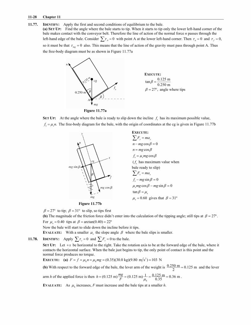
11-28 Chapter 11
11.77. IDENTIFY: Apply the first and second conditions of equilibrium to the bale.
(a) SET UP: Find the angle where the bale starts to tip. When it starts to tip only the lower left-hand corner of the
bale makes contact with the conveyor belt. Therefore the line of action of the normal force n passes through the
left-hand edge of the bale. Consider 0A* "+ with point A at the lower left-hand corner. Then 0n* " and 0,f* "
so it must be that 0mg* " also. This means that the line of action of the gravity must pass through point A. Thus
the free-body diagram must be as shown in Figure 11.77a
EXECUTE:
0.125 mtan
0.250 m? "
27 ,? " , angle where tips
Figure 11.77a
SET UP: At the angle where the bale is ready to slip down the incline sf has its maximum possible value,
s s .f n-" The free-body diagram for the bale, with the origin of coordinates at the cg is given in Figure 11.77b
EXECUTE:
y yF ma"+
cos 0n mg ?# "
cosn mg ?"
s s cosf mg- ?"
s( f has maximum value when
bale ready to slip)
x xF ma"+
s sin 0f mg ?# "
s cos sin 0mg mg- ? ?# "
stan? -"
s 0.60- " gives that 31? " ,
Figure 11.77b
27? " , to tip; 31? " , to slip, so tips first
(b) The magnitude of the friction force didn�t enter into the calculation of the tipping angle; still tips at 27 .? " ,
For s 0.40- " tips at arctan(0.40) 22? " " ,
Now the bale will start to slide down the incline before it tips.
EVALUATE: With a smaller s- the slope angle ? where the bale slips is smaller.
11.78. IDENTIFY: Apply 0z* "+ and 0xF "+ to the bale.
SET UP: Let x! be horizontal to the right. Take the rotation axis to be at the forward edge of the bale, where it
contacts the horizontal surface. When the bale just begins to tip, the only point of contact is this point and the
normal force produces no torque.
EXECUTE: (a) 2
k k (0.35)(30.0 kg)(9.80 m s ) 103 NF f n mg- -" " " " "
(b) With respect to the forward edge of the bale, the lever arm of the weight is 0.250 m 0.125 m2
" and the lever
arm h of the applied force is then k
0.125 m1(0.125 m) (0.125 m) 0.36 m0.35
mgh
F -" " " " .
EVALUATE: As k- increases, F must increase and the bale tips at a smaller h.

Equilibrium and Elasticity 11-29
11.79. IDENTIFY: Apply the first and second conditions of equilibrium to the door.
(a) SET UP: The free-body diagram for the door is given in Figure 11.79.
Figure 11.79
Take the origin of coordinates at the center of the door (at the cg). Let An k ,Af ,Bn and kBf be the normal and
friction forces exerted on the door at each wheel.
EXECUTE: y yF ma"+
0A Bn n w! # "
950 NA Bn n w! " "
x xF ma"+
k k 0A Bf f F! # "
k kA BF f f" !
k k ,A Af n-" k k ,B Bf n-" so k k( ) (0.52)(950 N) 494 NA BF n n w- -" ! " " "
0B* "+
,Bn k ,Af and kBf all have zero moment arms and hence zero torque about this point.
Thus (1.00 m) (2.00 m) ( ) 0Aw n F h! # # "
(1.00 m) ( ) (950 N)(1.00 m) (494 N)(1.60 m)80 N
2.00 m 2.00 mA
w F hn
# #" " "
And then 950 N 950 N 80 N 870 N.B An n" # " # "
(b) SET UP: If h is too large the torque of F will cause wheel A to leave the track. When wheel A just starts to lift
off the track An and kAf both go to zero.
EXECUTE: The equations in part (a) still apply.
0A Bn n w! # " gives 950 NBn w" "
Then k k 0.52(950 N) 494 NB Bf n-" " "
k k 494 NA BF f f" ! "
(1.00 m) (2.00 m) ( ) 0Aw n F h! # # "
(1.00 m) (950 N)(1.00 m)1.92 m
494 N
wh
F" " "
EVALUATE: The result in part (b) is larger than the value of h in part (a). Increasing h increases the clockwise
torque about B due to F and therefore decreases the clockwise torque that An must apply.
11.80. IDENTIFY: Apply the first and second conditions for equilibrium to the boom.
SET UP: Take the rotation axis at the left end of the boom.
EXECUTE: (a) The magnitude of the torque exerted by the cable must equal the magnitude of the torque due to the
weight of the boom. The torque exerted by the cable about the left end is sinTL 1 . For any angle ,1
sin (180 ) sin ,1 1, # " so the tension T will be the same for either angle. The horizontal component of the force that
the pivot exerts on the boom will be cos or cos(180 ) cosT T T1 1 1, # " # .
(b) From the result of part (a), T is proportional to 1
sin1 and this becomes infinite as 0 or 180 .1 17 7 ,
(c) The tension is a minimum when sin1 is a maximum, or 90 ,1 " , a vertical cable.
(d) There are no other horizontal forces, so for the boom to be in equilibrium, the pivot exerts zero horizontal force
on the boom.

11-30 Chapter 11
EVALUATE: As the cable approaches the horizontal direction, its moment arm for the axis at the pivot approaches zero,
so T must go to infinity in order for the torque due to the cable to continue to equal the gravity torque.
11.81. IDENTIFY: Apply the first and second conditions of equilibrium to the pole.
(a) SET UP: The free-body diagram for the pole is given in Figure 11.81.
n and f are the vertical and
horizontal components of the force
the ground exerts on the pole.
x xF ma"+
0f "
The force exerted by the ground
has no horizontal component.
Figure 11.81
EXECUTE: 0A* "+
(7.0 m)cos (4.5 m)cos 0T mg1 1! # "
(4.5 m/7.0 m) (4.5/ 7.0)(5700 N) 3700 NT mg" " "
0yF "+
0n T mg! # "
5700 N 3700 N 2000 Nn mg T" # " # "
The force exerted by the ground is vertical (upward) and has magnitude 2000 N.
EVALUATE: We can verify that 0z* "+ for an axis at the cg of the pole. T n3 since T acts at a point closer to
the cg and therefore has a smaller moment arm for this axis than n does.
(b) In the 0A* "+ equation the angle 1 divided out. All forces on the pole are vertical and their moment arms
are all proportional to cos .1
11.82. IDENTIFY: Apply the equilibrium conditions to the pole. The horizontal component of the tension in the wire is
22.0 N.
SET UP: The free-body diagram for the pole is given in Figure 11.82. The tension in the cord equals the weight
W. vF and hF are the components of the force exerted by the hinge. If either of these forces is actually in the
opposite direction to what we have assumed, we will get a negative value when we solve for it.
EXECUTE: (a) sin37.0 22.0 NT "! so 36.6 NT " . 0z* "+ gives ( sin37.0 )(1.75 m) (1.35 m) 0T W# "! .
(22.0 N)(1.75 m)28.5 N
1.35 mW " " .
(b) 0yF "+ gives v cos37.0 0F T W# # "! and v (36.6 N)cos37.0 55.0 N 84.2 NF " ! "! . 0xF "+ gives
hsin37.0 0W T F# # "! and h 28.5 N 22.0 N 6.5 NF " # " . The magnitude of the hinge force is
2 2
h v 84.5 NF F F" ! " .
EVALUATE: If we consider torques about an axis at the top of the plate, we see that hF must be to the left in order
for its torque to oppose the torque produced by the force W.
Figure 11.82

Equilibrium and Elasticity 11-31
11.83. IDENTIFY: Apply 0z* "+ to the slab.
SET UP: The free-body diagram is given in Figure 11.83a. 3.75 m
tan1.75 m
? " so 65.0? " ! . 20.0 90? 8! ! "! ! so
5.08 " ! . The distance from the axis to the center of the block is
2 23.75 m 1.75 m
2.07 m2 2
$ % $ %! "& ' & '( ) ( )
.
EXECUTE: (a) (2.07 m)sin5.0 (3.75 m)sin52.0 0w T# "! ! . 0.061T w" . Each worker must exert a force of
0.012w , where w is the weight of the slab.
(b) As 1 increases, the moment arm for w decreases and the moment arm for T increases, so the worker needs to
exert less force.
(c) 0T 7 when w passes through the support point. This situation is sketched in Figure 11.83b.
(1.75 m) / 2tan
(3.75 m) / 21 " and 25.01 " ! . If 1 exceeds this value the gravity torque causes the slab to tip over.
EVALUATE: The moment arm for T is much greater than the moment arm for w, so the force the workers apply is
much less than the weight of the slab.
Figure 11.83a, b
11.84. IDENTIFY: For a spring, F kx" . 0F lY
A l
4"5
.
SET UP: F F W4 " " and l x5 " . For copper, 1011 10 PaY " 2 .
EXECUTE: (a) 0 0
YA YAF l x
l l
$ % $ %" 5 "& ' & '( ) ( )
. This in the form of F kx" , with 0
YAk
l" .
(b) 10 4 2
5
0
(11 10 Pa) (6.455 10 m)1.9 10 N/m
0.750 m
YAk
l
6 #2 2" " " 2
(c) 5 3(1.9 10 N/m)(1.25 10 m) 240 NW kx #" " 2 2 "
EVALUATE: For the wire the force constant is very large, much larger than for a typical spring.
11.85. IDENTIFY: Apply Newton�s 2nd law to the mass to find the tension in the wire. Then apply Eq.(11.10) to the wire
to find the elongation this tensile force produces.
(a) SET UP: Calculate the tension in the wire as the mass passes through the lowest point. The free-body diagram
for the mass is given in Figure 11.85a.
The mass moves in an arc of a circle
with radius 0.50 m.R " It has
acceleration rada!
directed in toward
the center of the circle, so at this point
rada!
is upward.
Figure 11.85a
EXECUTE: y yF ma"+
2T mg mR@# " so that 2( ).T m g R@" !

11-32 Chapter 11
But @ must be in rad/s:
(120 rev/min)(2 rad/1 rev)(1 min/60 s) 12.57 rad/s.@ 6" "
Then 2 2(12.0 kg)(9.80 m/s (0.50 m)(12.57 rad/s) ) 1066 N.T " ! "
Now calculate the elongation l5 of the wire that this tensile force produces:
0
F lY
A l
4"5
so 0
10 4 2
(1066 N)(0.50 m)0.54 cm.
(7.0 10 Pa)(0.014 10 m )
F ll
YA
4#
5 " " "2 2
(b) SET UP: The acceleration rada!
is directed in towards the center of the circular path, and at this point in the
motion this direction is downward. The free-body diagram is given in Figure 11.85b.
EXECUTE:
y yF ma"+
2mg T mR@! "
2( )T m R g@" #
Figure 11.85b 2 2(12.0 kg)((0.50 m)(12.57 rad/s) 9.80 m/s ) 830 NT " # "
0
10 4 2
(830 N)(0.50 m)0.42 cm.
(7.0 10 Pa)(0.014 10 m )
F ll
YA
4#
5 " " "2 2
EVALUATE: At the lowest point T and w are in opposite directions and at the highest point they are in the same
direction, so T is greater at the lowest point and the elongation is greatest there. The elongation is at most 1% of the
length.
11.86. IDENTIFY: 0
YAF l
l4
$ %" 5& '( )
so the slope of the graph in part (a) depends on Young�s modulus.
SET UP: F4 is the total load, 20 N plus the added load.
EXECUTE: (a) The graph is given in Figure 11.86.
(b) The slope is 4
2
60 N2.0 10 N/m
(3.32 3.02) 10 m#" 2
# 2.
4 4 110
2 3 2
3.50 m(2.0 10 N/m)= (2.0 10 N/m) 1.8 10 Pa
[0.35 10 m]
lY
r6 6 #
$ %$ %" 2 2 " 2& '& ' 2( ) ( )
(c) The stress is /F A4 . The total load at the proportional limit is 60 N 20 N 80 N! " .
8
3 2
80 Nstress 2.1 10 Pa
(0.35 10 m)6 #" " 2
2
EVALUATE: The value of Y we calculated is close to the value for iron, nickel and steel in Table 11.1.
Figure 11.86

Equilibrium and Elasticity 11-33
11.87. IDENTIFY: Use the second condition of equilibrium to relate the tension in the two wires to the distance w is from
the left end. Use Eqs.(11.8) and (11.10) to relate the tension in each wire to its stress and strain.
(a) SET UP: stress / ,F A4" so equal stress implies /T A same for each wire.
2 2/ 2.00 mm / 4.00 mmA BT T" so 2.00B AT T"
The question is where along the rod to hang the weight in order to produce this relation between the tensions in the
two wires. Let the weight be suspended at point C, a distance x to the right of wire A. The free-body diagram for
the rod is given in Figure 11.87.
EXECUTE:
0C* "+
(1.05 m ) 0B AT x T x! # # "
Figure 11.87
But 2.00B AT T" so 2.00 (1.05 m ) 0A AT x T x# # "
2.10 m 2.00x x# " and 2.10 m/3.00 0.70 mx " " (measured from A).
(b) SET UP: stress/strainY " gives that strain stress / / .Y F AY4" "
EXECUTE: Equal strain thus implies
2 11 2 11(2.00 mm )(1.80 10 Pa) (4.00 mm )(1.20 10 Pa)
A BT T"
2 2
4.00 1.201.333 .
2.00 1.80B A AT T T
$ %$ %" "& '& '( )( )
The 0C* "+ equation still gives (1.05 m ) 0.B AT x T x# # "
But now 1.333B AT T" so (1.333 )(1.05 m ) 0A AT x T x# # "
1.40 m 2.33x" and 1.40 m/2.33 0.60 mx " " (measured from A).
EVALUATE: Wire B has twice the diameter so it takes twice the tension to produce the same stress. For equal
stress the moment arm for BT (0.35 m) is half that for AT (0.70 m), since the torques must be equal. The smaller Y
for B partially compensates for the larger area in determining the strain and for equal strain the moment arms are
closer to being equal.
11.88. IDENTIFY: Apply Eq.(11.10) and calculate l5 .
SET UP: When the ride is at rest the tension F4 in the rod is the weight 1900 N of the car and occupants. When
the ride is operating, the tension F4 in the rod is obtained by applying m"+F a! !
to a car and its occupants. The
free-body diagram is shown in Figure 11.88. The car travels in a circle of radius sinr l 1" , where l is the length of
the rod and 1 is the angle the rod makes with the vertical. For steel, 112.0 10 PaY " 2 .
8.00 rev/min 0.838 rad/s@ " " .
EXECUTE: (a) 40
11 4 2
(15.0 m)(1900 N)1.78 10 m 0.18 mm
(2.0 10 Pa)(8.00 10 m )
l Fl
YA
#4#
5 " " " 2 "2 2
(b) x xF ma"+ gives 2 2sin sinF mr ml1 @ 1@4 " " and
2 2 3
2
1900 N(15.0 m)(0.838 rad/s) 2.04 10 N
9.80 m/sF ml@4
$ %" " " 2& '( )
. 32.04 10 N
(0.18 mm) 0.19 mm1900 N
l$ %2
5 " "& '( )
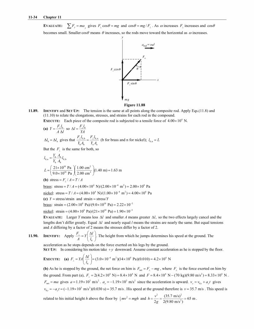
11-34 Chapter 11
EVALUATE: y yF ma"+ gives cosF mg14 " and cos /mg F1 4" . As @ increases F4 increases and cos1
becomes small. Smaller cos1 means 1 increases, so the rods move toward the horizontal as @ increases.
Figure 11.88
11.89. IDENTIFY and SET UP: The tension is the same at all points along the composite rod. Apply Eqs.(11.8) and
(11.10) to relate the elongations, stresses, and strains for each rod in the compound.
EXECUTE: Each piece of the composite rod is subjected to a tensile force of 44.00 10 N.2
(a) 0
F lY
A l
4"5
so 0F ll
YA
45 "
b nl l5 " 5 gives that 0,b 0,n
b b n n
F l F l
Y A Y A
4 4" (b for brass and n for nickel); 0,nl L"
But the F4 is the same for both, so
n n0,n 0,b
b b
Y Al l
Y A"
10 2
10 2
21 10 Pa 1.00 cm(1.40 m) 1.63 m
9.0 10 Pa 2.00 cmL
$ %$ %2" "& '& '
2( )( )
(b) stress / /F A T A4" "
brass: 4 4 2 8stress / (4.00 10 N)/(2.00 10 m ) 2.00 10 PaT A #" " 2 2 " 2
nickel: 4 4 2 8stress / (4.00 10 N)/(1.00 10 m ) 4.00 10 PaT A #" " 2 2 " 2
(c) stress/strainY " and strain stress/Y"
brass: 8 10 3strain (2.00 10 Pa)/(9.0 10 Pa) 2.22 10#" 2 2 " 2
nickel: 8 10 3strain (4.00 10 Pa)/(21 10 Pa) 1.90 10#" 2 2 " 2
EVALUATE: Larger Y means less l5 and smaller A means greater ,l5 so the two effects largely cancel and the
lengths don�t differ greatly. Equal l5 and nearly equal l means the strains are nearly the same. But equal tensions
and A differing by a factor of 2 means the stresses differ by a factor of 2.
11.90. IDENTIFY: Apply 0
F lY
A l
4 $ %5" & '
( ). The height from which he jumps determines his speed at the ground. The
acceleration as he stops depends on the force exerted on his legs by the ground.
SET UP: In considering his motion take y! downward. Assume constant acceleration as he is stopped by the floor.
EXECUTE: (a) 4 2 9 4
0
(3.0 10 m )(14 10 Pa)(0.010) 4.2 10 Nl
F YAl
#4
$ %5" " 2 2 " 2& '
( )
(b) As he is stopped by the ground, the net force on him is netF F mg4" # , where F4 is the force exerted on him by
the ground. From part (a), 4 42(4.2 10 N) 8.4 10 NF4 " 2 " 2 and 4 2 48.4 10 N (70 kg)(9.80 m/s ) 8.33 10 NF " 2 # " 2 .
netF ma" gives 3 21.19 10 m/sa " 2 . 3 21.19 10 m/sya " # 2 since the acceleration is upward. 0y y yv v a t" ! gives
3 2
0 ( 1.19 10 m/s )(0.030 s) 35.7 m/sy yv a t" # " # 2 " . His speed at the ground therefore is 35.7 m/sv " . This speed is
related to his initial height h above the floor by 21
2mv mgh" and
2 2
2
(35.7 m/s)65 m
2 2(9.80 m/s )
vh
g" " " .

Equilibrium and Elasticity 11-35
EVALUATE: Our estimate is based solely on compressive stress; other injuries are likely at a much lower height.
11.91. IDENTIFY and SET UP: 0 / Y F l A l4" 5 (Eq.11.10 holds since the problem states that the stress is proportional to
the strain.) Thus 0 / .l F l AY45 " Use proportionality to see how changing the wire properties affects .l5
EXECUTE: (a) Change 0l but F4 (same floodlamp), A (same diameter wire), and Y (same material) all stay the
same.
0
constant,l F
l AY
45" " so 1 2
01 02
l l
l l
5 5"
5 5
2 1 02 01 1( / ) 2 2(0.18 mm) 0.36 mml l l l l5 " 5 " 5 " "
(b) 2 21
4( / 2) ,A d d6 6" " so 0
214
F ll
d Y645 "
,F4 0 ,l Y all stay the same, so / 02 10 4
( ) / constantl d F l Y645 " "
2 2
1 1 2 2( ) ( )l d l d5 " 5
2 2
2 1 1 2( / ) (0.18 mm)(1/2) 0.045 mml l d d5 " 5 " "
(c) ,F4 0 ,l A all stay the same so 0 / constantlY F l A45 " "
1 1 2 2l Y l Y5 " 5
10 10
2 1 1 2( / ) (0.18 mm)(20 10 Pa/11 10 Pa) 0.33 mml l Y Y5 " 5 " 2 2 "
EVALUATE: Greater l means greater ,l5 greater diameter means less ,l5 and smaller Y means greater .l5
11.92. IDENTIFY: Apply Eq.(11.13) and calculate V5 .
SET UP: The pressure increase is /w A , where w is the weight of the bricks and A is the area 2r6 of the piston.
EXECUTE: 2
5
2
(1420 kg)(9.80 m/s )1.97 10 Pa
(0.150 m)p
65 " " 2
0
Vp B
V
55 " # gives
5
0
8
( ) (1.97 10 Pa)(250 L)0.0542 L
9.09 10 Pa
p VV
B
5 25 " # " # " #
2
EVALUATE: The fractional change in volume is only 0.022%, so this attempt is not worth the effort.
11.93. IDENTIFY and SET UP: Apply Eqs.(11.8) and (11.15). The tensile stress depends on the component of F!
perpendicular to the plane and the shear stress depends on the component of F!
parallel to the plane. The forces
are shown in Figure 11.93a
Figure 11.93a
(a) EXECUTE: The components of F are shown in Figure 11.93b.
The area of the diagonal
face is / cos .A 1
Figure 11.93b
2costensile stress cos /( / cos ) .
( / cos )
F FF A
A A
11 1
14" " "
(b) sin cos sin 2
shear stress sin /( / cos )( / cos ) 2
F F FF A
A A A
1 1 11 1
1" " " ""
(using a trig identity).
EVALUATE: (c) From the result of part (a) the tensile stress is a maximum for cos 1,1 " so 0 .1 " ,
(d) From the result of part (b) the shear stress is a maximum for sin 2 1,1 " so for 2 901 " , and thus 451 " ,

11-36 Chapter 11
11.94. IDENTIFY: Apply the first and second conditions of equilibrium to the rod. Then apply Eq.(11.10) to relate the
compressive force on the rod to its change in length.
SET UP: For copper, 111.1 10 PaY " 2 .
EXECUTE: (a) Taking torques about the pivot, the tensionT in the cable is related to the weight by
0 0(sin ) 2, so .2sin
mgT l mgl T1
1" " The horizontal component of the force that the cable exerts on the rod, and
hence the horizontal component of the force that the pivot exerts on the rod, is cot2
mg1 and the stress is cot .
2
mg
A1
(b) 0 0 cot.
2
l F mgll
AY AY
15 " " l5 corresponds to a decrease in length.
(c) In terms of the density and length, 0( ) ,m A lA" so the stress is 0( 2)cotl gA 1 and the change in length is
2
0( 2 )cotl g YA 1 .
(d) Using the numerical values, the stress is 51.4 102 Pa and the change in length is 62.2 10 m.#2
(e) The stress is proportional to the length and the change in length is proportional to the square of the length, and
so the quantities change by factors of 2 and 4.
EVALUATE: The compressive force and therefore the decrease in length increase as 1 decreases and the cable
becomes more nearly horizontal.
11.95. IDENTIFY: Apply the first and second conditions for equilibrium to the bookcase.
SET UP: When the bookcase is on the verge of tipping, it contacts the floor only at its lower left-hand edge and
the normal force acts at this point. When the bookcase is on the verge of slipping, the static friction force has its
largest possible value, sn- .
EXECUTE: (a) Taking torques about the left edge of the left leg, the bookcase would tip when
(1500 )(0.90 m)750
(1.80 m)F
B" " B and would slip when s( )(1500 ) 600 ,F -" B " B so the bookcase slides before
tipping.
(b) If F is vertical, there will be no net horizontal force and the bookcase could not slide. Again taking torques
about the left edge of the left leg, the force necessary to tip the case is (1500 )(0.90 m)
13.5 kN(0.10 m)
B" .
(c) To slide, the friction force is s ( cos ),f w F- 1" ! and setting this equal to sinF 1 and solving for F gives
s
ssin cos
wF
-1 - 1
"#
(to slide). To tip, the condition is that the normal force exerted by the right leg is zero, and
taking torques about the left edge of the left leg, sin (1.80 m) cos (0.10 m) (0.90 m),F F w1 1! " and solving for
F gives (1 9)cos 2sin
wF
1 1"
! (to tip). Setting the two expressions equal to each other gives
s s((1 9)cos 2sin ) sin cos- 1 1 1 - 1! " # and solving for1 gives s
s
(10 9)arctan 66 .
(1 2 )
-1
-$ %
" " ,& '#( )
EVALUATE: The result in (c) depends not only on the numerical value of s- but also on the width and height of
the bookcase.
11.96. IDENTIFY: Apply 0z* "+ to the post, for various choices of the location of the rotation axis.
SET UP: When the post is on the verge of slipping, sf has its largest possible value, s sf n-" .
EXECUTE: (a) Taking torques about the point where the rope is fastened to the ground, the lever arm of the applied
force is / 2h and the lever arm of both the weight and the normal force is tan ,h 1 and so ( ) tan .2hF n w h 1" #
Taking torques about the upper point (where the rope is attached to the post), .2hfh F" Using sf n-C and solving
for F,
1 1
s
1 1 1 12 2(400 N) 400 N
tan 0.30 tan36.9F w
- 1
# #$ % $ %C # " # "& ' & ',( )( ).
(b) The above relations between , and becomeF n f3 2
( ) tan , ,5 5
F h n w h f F1" # " and eliminating f and n and
solving for F gives
1
s
2 5 3 5,
tanF w
- 1
#$ %
C #& '( )
and substitution of numerical values gives 750 N to two figures.

Equilibrium and Elasticity 11-37
(c) If the force is applied a distance y above the ground, the above relations become
( ) tan , ( ) ,Fy n w h F h y fh1" # # " which become, on eliminating and ,n f / 0 / 0
s
1 / /.
tan
y h y hw F
- 1D E#
> #F GH I
As the
term in square brackets approaches zero, the necessary force becomes unboundedly large. The limiting value of y
is found by setting the term in square brackets equal to zero. Solving for y gives
tan tan36.90.71.
tan 0.30 tan36.9s
y
h
1- 1
," " "
! ! ,
EVALUATE: For the post to slip, for an axis at the top of the post the torque due to F must balance the torque due
to the friction force. As the point of application of F approaches the top of the post, its moment arm for this axis
approaches zero.
11.97. IDENTIFY: Apply 0z* "+ to the girder.
SET UP: Assume that the center of gravity of the loaded girder is at 2,L and that the cable is attached a distance
x to the right of the pivot. The sine of the angle between the lever arm and the cable is then 2 2(( 2) )h h L x! # .
EXECUTE: The tension is obtained from balancing torques about the pivot;
2 22,
(( 2) )
hxT wL
h L x
D EF G "F G! #H I
where w is the total load . The minimum tension will occur when the term in
square brackets is a maximum; differentiating and setting the derivative equal to zero gives a maximum, and hence
a minimum tension, at 2
min ( ) ( 2).x h L L" ! However, if min , which occurs if 2,x L h L3 3 the cable must be
attached at L, the farthest point to the right.
EVALUATE: Note that minx is greater than / 2L but approaches / 2L as 0h 7 . The tension is a minimum when
the cable is attached somewhere on the right-hand half of the girder.
11.98. IDENTIFY: Apply the equilibrium conditions to the ladder combination and also to each ladder.
SET UP: The geometry of the 3-4-5 right triangle simplifies some of the intermediate algebra. Denote the forces
on the ends of the ladders by and L RF F (left and right). The contact forces at the ground will be vertical, since the
floor is assumed to be frictionless.
EXECUTE: (a) Taking torques about the right end, (5.00 m) (480 N)(3.40 m) (360 N)(0.90 m)LF " ! , so
391 NLF " . RF may be found in a similar manner, or from 840 N 449 N.R LF F" # "
(b) The tension in the rope may be found by finding the torque on each ladder, using the point A as the origin. The
lever arm of the rope is 1.50 m. For the left ladder, (1.50 m) (3.20 m) (480 N)(1.60 m), so 322.1 NLT F T" # "
(322 N to three figures). As a check, using the torques on the right ladder, (1.50 m) (1.80 m) (360 N)(0.90 m)RT F" #
gives the same result.
(c) The horizontal component of the force at A must be equal to the tension found in part (b). The vertical force
must be equal in magnitude to the difference between the weight of each ladder and the force on the bottom of
each ladder, 480 N 391 N 449 N 360 N 89 N.# " # " The magnitude of the force at A is then
2 2(322.1 N) (89 N) 334 N.! "
(d) The easiest way to do this is to see that the added load will be distributed at the floor in such a way that
(0.36)(800 N) 679 N, and (0.64)(800 N) 961 N.L L R RF F F FJ J" ! " " ! " Using these forces in the form for the
tension found in part (b) gives
(3.20 m) (480 N)(1.60 m) (1.80 m) (360 N)(0.90 m)937 N
(1.50 m) (1.50 m)
L RF FT
J J# #" " " .
EVALUATE: The presence of the painter increases the tension in the rope, even though his weight is vertical and
the tension force is horizontal.
11.99. IDENTIFY: Apply Eq.(11.14) to each material, the oil and the sodium. For each material, /p F A5 " .
SET UP: The total volume change, totV5 , is related to the distance the piston moves by totV Ax5 " .
EXECUTE: The change in the volume of the oil is O Ok v p5 and the change in the volume of the sodium is s s .k v p5
Setting the total volume change equal to Ax (x is positive) and using ,p F A5 " O O s s( )( ),Ax k V k V F A" ! and
solving for sk gives 2
s O O
s
1A xk k V
F V
$ %" # .& '( )

11-38 Chapter 11
EVALUATE: Neglecting the volume change of the oil corresponds to setting O 0k " , and in that case 2
s
s
A xk
FV" . In
either case, x is larger when sk is larger.
11.100. IDENTIFY: Write ( )pV5 or ( )pV K5 in terms of p5 and V5 and use the fact that pV or pV K is constant.
SET UP: B is given by Eq.(11.13).
EXECUTE: (a) For constant temperature / 00T5 " , ( ) ( ) ( ) 0pV p V p V5 " 5 ! 5 " and / 0( )p V
B pV
5" # "
5.
(b) In this situation, / 0 1( ) 0, ( ) 0,( Vp V (p V V p (p
V
K # 55 ! 5 " 5 ! " and
( ).
p VB (p
V
5" # "
5
EVALUATE: We will see later that 1K 3 , so B is larger in part (b).
11.101. IDENTIFY: Apply Eq.(11.10) to calculate l5 .
SET UP: For steel, 112.0 10 PaY " 2 .
EXECUTE: (a) From Eq.(11.10), 2
4
10 7
2
(4.50 kg)(9.80 m/s )(1.50 m) 6.62 10 m, or 0.66 mm
(20 10 Pa)(5.00 10 m )l #
#5 " " 2
2 2to two figures.
(b) 2 2(4.50 kg)(9.80 m s )(0.0500 10 m) 0.022 J.#2 "
(c) The magnitude F will vary with distance; the average force is 0(0.0250 cm ) 16.7 N,YA l " and so the work
done by the applied force is 2 3(16.7 N)(0.0500 10 m) 8.35 10 J.# #2 " 2
(d) The average force the wire exerts is (450 kg) 16.7 N 60.8 N.g ! " The work done is negative, and equal to
2 2(60.8 N)(0.0500 10 m) 3.04 10 J.# ## 2 " # 2
(e) Eq.(11.10) is in the form of Hooke�s law, with 0
YAk
l" . 21
el 2U kx" , so 2 21
el 2 12( )U k x x5 " # .
4
1 6.62 10 mx #" 2 and 3 4
2 10.500 10 m 11.62 10 mx x# #" 2 ! " 2 . The change in elastic potential energy is
/ 0
10 7 24 2 4 2 2(20 10 Pa)(5.00 10 m )
((11.62 10 m) (6.62 10 m) ) 3.04 10 J,2 1.50 m
## # #2 2
2 # 2 " 2 the negative of the result of
part (d).
EVALUATE: The tensile force in the wire is conservative and obeys the relation W U" #5 .