Embed Size (px)
Citation preview
CCEC/Product Data /CCEC PDS RotaSec FOS 91 En 1.2 - 1 - 02.2007
Technical Specifications Drive: Hand operated Orientation: Pass Left or Pass right Materials: Casework: 304 Grade grained stainless steel..
Rotor Wings: 304 Grade grained stainless steel. Rotor Spindle: Tubolar 304 Grade grained stainless steel.
Function: Passage in both directions, electronically controllable. Mechanism: Control of the RotaSec FOS 91 operation is achieved by an electro-mechanical
head mechanism lacated in the roof drum of the RotaSec FOS 91. It is silent in rotation and comprises the following standard features:
• A positive action lock which prevents two passages at one time • A Self centering mechanism to ensure complete rotation of the head to the
rest position. • An anti backup device prevents reverse rotation once the head has moved
30O from its rest position. • A hydraulic damper to ensure smooth and quiet operation
Operating Modes: The mechanism can be configured to operate in two standard modes.
• Normally Closed – The mechanism is locked until a valid authorisation signal is received.
• Normally Open – The mechanism is permanently unlocked and will only lock if passage is attempted without a valid authorised signal. In this mode the MTBF is increased from 1.5 to 2.5 million cycles and increases passage throughput speeds.
Power Failure: In the event of an emergency or isolation of power supply, unit may be
configured to fail-safe i.e. rotor freely rotates or fail-lock i.e. rotor locks. Either option is available in both or one direction. Choice must be denoted at time of order placement.
Note - Head mechanism fail state will be the same as power failure choice.
Interface: The mechanism is controlled by means of a LCM02 microprocessor control logic
with the following features :
• One input for opening/locking the mechanism in each direction. • Two protected outputs for control of the opening/locking solenoids. • Four protected outputs for piloting way mode indicators. • Two 0V output relays indicating availability of use in either direction. • Two 0V outputs to count passage in either direction.
Unit has an adjustable time out facility if required i.e. Go signal will be cancelled if passage through turnstile is not completed within pre-set time. The standard default is 8 seconds adjustable via parameter change. Additional detailed information is available upon request.
Servicing: From top of the roof
RotaSec FOS 91 Manual security Turnstile
RotaSec FOS 91
Product Description Engineered for outdoor high-security areas, the RotaSec FOS 91 is intended for applications requiring a high-performance turnstile with an elegant design.
Users include • Government • Retail • Finance • Telecommunications • Information
Technology • Banking • Publishing • Leisure • Petrochemical • Pharmaceutical • Education
Restrict
CCEC/Product Data /CCEC PDS RotaSec FOS 91 En 1.2 - 2 - 02.2007
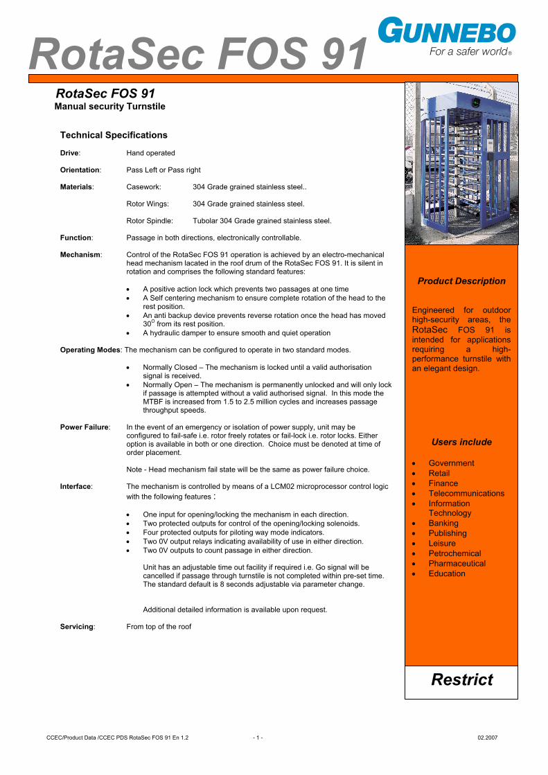
Installation Examples
Power Supply: 115/230 Volts AC 50/60 Hz Power Rating: RotaSec FOS 91S 50VA (without lights option) RotaSec FOS 91D 100VA (without lights option) Logic Voltage: 24 Volt DC Installation Details: RotaSec FOS 91 models are delivered as one piece, which may require lifting gear for off loading. Approx. weight (depending on spec.) :
RotaSec FOS 91S 470 kg. RotaSec FOS 91D 660 kg.
Available models • RotaSec FOS91 S model Single walkway • RotaSec FOS91 D model Double walkway Extra Accessories and Optionals Alternative Materials, Finishes and Custom Design • Refer to Gunnebo Entrance Control Ltd. for specific material design requirements. • Entry/ Exit roof. • Halogen internal lights. Cardreader Mounting (Please refer to Gunnebo Entrance Control Ltd. for feasibility) • Integration of customer supplied readers onto the RotaSec FOS casework uprights. • Cardreader Pedestals. Traffic Lights • LED Red Cross and Green Arrow displays Push Button Control • MP20 remote control (COM R1 board requiered).. • Remote console to specific requirements. • Casework mounted push button. Additional Interface • RS 485 Serial Interface Counting • LCD Counter • Electro-mechanical Counter
CCEC/Product Data /CCEC PDS RotaSec FOS 91 En 1.2 - 3 - 02.2007
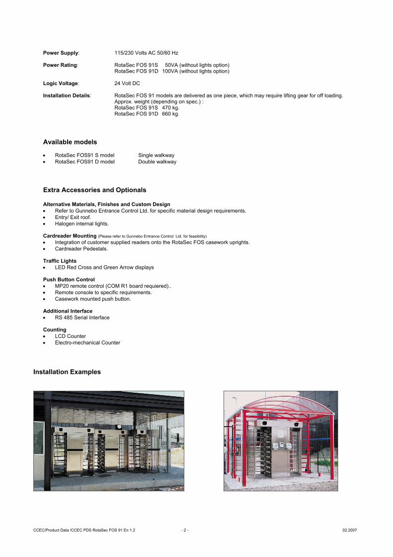
RotaSec FOS 91S Site Preparation.
Cable entry zone
Concrete to UNI 9858, RCK250 type. Base to be flat and level to +/- 5mm over the RotaSec FOS footprint area.
Cables metal conduit, shall come up at least 50mm from foundation
6 anchor holes for TPSEI M10 bolts x 125mm deep min. (drilled during installation)
IMPORTANT • Any horizontal pipe or conduit runs below the RotaSec FOS 91 must be at least 140mm below. • The dimension reported on this Product Data Sheet are for information only. In order to prepare the Installation Site,
please refer to the lay-out drawings prepared by Gunnebo Entrance Control Ltd or ask confirmation.
Unit in mm
CCEC/Product Data /CCEC PDS RotaSec FOS 91 En 1.2 - 4 - 02.2007
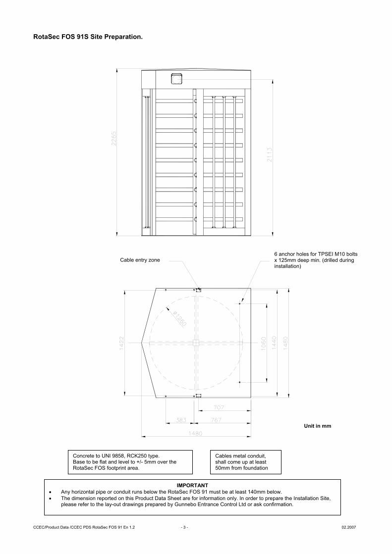
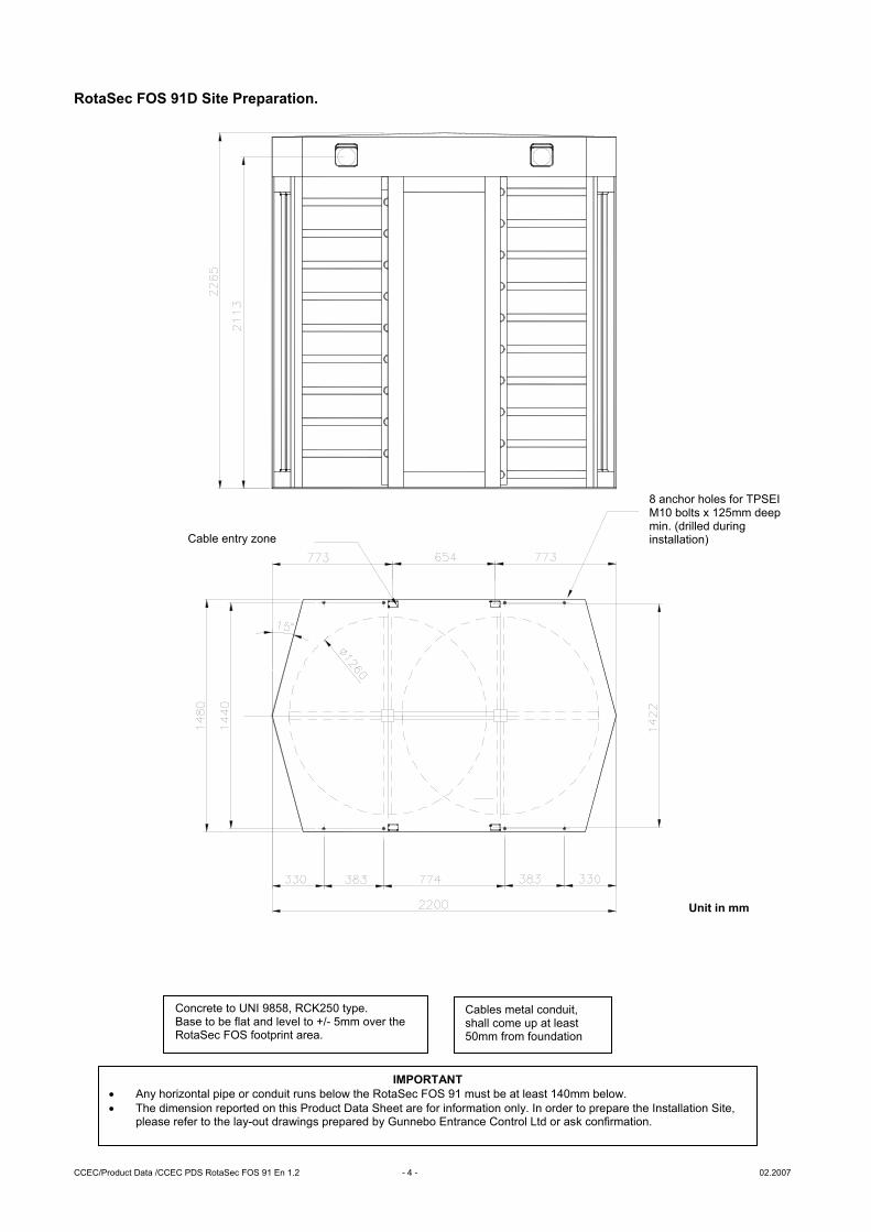
RotaSec FOS 91D Site Preparation.
Cable entry zone
Cables metal conduit, shall come up at least 50mm from foundation
Concrete to UNI 9858, RCK250 type. Base to be flat and level to +/- 5mm over the RotaSec FOS footprint area.
8 anchor holes for TPSEI M10 bolts x 125mm deep min. (drilled during installation)
IMPORTANT • Any horizontal pipe or conduit runs below the RotaSec FOS 91 must be at least 140mm below. • The dimension reported on this Product Data Sheet are for information only. In order to prepare the Installation Site,
please refer to the lay-out drawings prepared by Gunnebo Entrance Control Ltd or ask confirmation.
Unit in mm
CCEC/Product Data /CCEC PDS RotaSec FOS 91 En 1.2 - 5 - 02.2007
Flow Rates
Reader Device Number per minute Insertion type 12 Insertion type with PIN code keypad 7.5 Swipe type 15 Swipe type with PIN code keypad 8.5 Proximity ‘Hands Free’ 17
• Please note the figures are approximate and must be confirmed with Gunnebo Entrance Control Ltd
Figures quoted are for one person per complete passage per walkway and per minute. It is assumed the access control authorisation response is instantaneous. Flow rates will increase with multiple passage use.
A COMPANY WITHIN THE GUNNEBO GROUP
HEAD OFFICE SWEDEN
Gunnebo AB, Box 5181, SE-402 26 Goteborg, SWEDEN. Tel +46-31 83 68 00, Fax +46-31 83 68 10
www.gunnebo.com
Note: In pursuit of its policy of continuous refinement and improvement, Gunnebo Entrance Control Ltd reserves the right to modify design and details.
For sales enquiries please contact:
________________________________
Competence Centre Entrance Control
Gunnebo Entrance Control Ltd. Bellbrook Business Park, Uckfield, East Sussex, TN22 1QQ, UK. Tel +44 (0) 1825 761022 Fax +44 (0) 1825 763835
E-mail [email protected] Web www.gunnebo.com
ISO 9001 FM 13503