Embed Size (px)
Citation preview

WARRANTY.....Top Flite® Models guarantees this kit to be free from defects in both material and workmanship at the date of purchase. This warrantydoes not cover any component parts damaged by use or modification. In no case shall Top Flite’s liability exceed the original cost of the purchased kit. Further, Top Flitereserves the right to change or modify this warranty without notice. In that Top Flite has no control over the final assembly or material used for final assembly, no liability shallbe assumed nor accepted for any damage resulting from the use by the user of the final user-assembled product. By the act of using the user-assembled product, the useraccepts all resulting liability. If the buyer is not prepared to accept the liability associated with the use of this product, the buyer is advised to return this kit immediatelyin new and unused condition to the place of purchase.
Top Flite Models Champaign, IL Telephone (217) 398-8970, Ext. 5 [email protected]
READ THROUGH THIS INSTRUCTION BOOK FIRST. IT CONTAINS IMPORTANT INSTRUCTIONS AND WARNINGS CONCERNING THE ASSEMBLY AND USE OF THIS MODEL.
TOPZ9300 for TOPA1005 V1.0Entire Contents © Copyright 2003
Wingspan: 50.5 in [1,285mm]Wing Area: 500 sq in [32.2 dm2]Weight: 42 – 50 oz [1,190 – 1,420g]Wing Loading: 12 – 14 oz/sq ft
[37 – 43 g/dm2]Length: 38.5 in [980mm] (tip of rudder
to tip of spinner)Engine: .35 – .46 cu in [5.5 – 7.5cc]
2-stroke glow
TABLE OF CONTENTS
INTRODUCTION . . . . . . . . . . . . . . . . . . . . . . . . . . 2IMPORTANT SAFETY PRECAUTIONS . . . . . . . . . 2ENGINE & LINE RECOMMENDATIONS. . . . . . . . . 3ADDITIONAL ITEMS REQUIRED. . . . . . . . . . . . . . 3
Hardware & Accessories. . . . . . . . . . . . . . . . . 3Adhesives & Building Supplies . . . . . . . . . . . . 3Optional Supplies & Tools . . . . . . . . . . . . . . . . 4Covering Tools . . . . . . . . . . . . . . . . . . . . . . . . 4
KIT INSPECTION . . . . . . . . . . . . . . . . . . . . . . . . . . 4ORDERING REPLACEMENT PARTS. . . . . . . . . . . 4KIT CONTENTS . . . . . . . . . . . . . . . . . . . . . . . . . . . 5IMPORTANT BUILDING NOTES . . . . . . . . . . . . . . 6ASSEMBLE THE WING . . . . . . . . . . . . . . . . . . . . . 6
Hinge the Flaps . . . . . . . . . . . . . . . . . . . . . . . 6Make the Flap Pushrod. . . . . . . . . . . . . . . . . . 7Join the Flaps to the Wing . . . . . . . . . . . . . . . 8Finish the Wing. . . . . . . . . . . . . . . . . . . . . . . . 9
ASSEMBLE THE FUSELAGE . . . . . . . . . . . . . . . 10Prepare the Stab . . . . . . . . . . . . . . . . . . . . . 10Make the Elevator Pushrod . . . . . . . . . . . . . . 12Mount the Fuel Tank . . . . . . . . . . . . . . . . . . . 12Join the Wing & Stab to the Fuselage . . . . . . 13Join the Fin & Tail Wheel. . . . . . . . . . . . . . . . 13Mount the Main Landing Gear. . . . . . . . . . . . 14Mount the Engine . . . . . . . . . . . . . . . . . . . . . 14Mount the Cowl. . . . . . . . . . . . . . . . . . . . . . . 15
FINAL DETAILS . . . . . . . . . . . . . . . . . . . . . . . . . . 17Mount the Canopy . . . . . . . . . . . . . . . . . . . . 17Apply the Decals. . . . . . . . . . . . . . . . . . . . . . 17
GET THE MODEL READY TO FLY . . . . . . . . . . . . 17Balance the Model (C.G.) . . . . . . . . . . . . . . . 17Wing Tip Weight . . . . . . . . . . . . . . . . . . . . . . 18
PREFLIGHT . . . . . . . . . . . . . . . . . . . . . . . . . . . . . 18Balance the Propellers . . . . . . . . . . . . . . . . . 18Engine Check . . . . . . . . . . . . . . . . . . . . . . . . 18Control Check. . . . . . . . . . . . . . . . . . . . . . . . 19
ENGINE SAFETY PRECAUTIONS . . . . . . . . . . . . 19AMA SAFETY CODE (excerpt) . . . . . . . . . . . . . . 19
General . . . . . . . . . . . . . . . . . . . . . . . . . . . . 19Control Line . . . . . . . . . . . . . . . . . . . . . . . . . 19
CHECK LIST . . . . . . . . . . . . . . . . . . . . . . . . . . . . 19FLYING . . . . . . . . . . . . . . . . . . . . . . . . . . . . . . . . 20
Flying Precautions . . . . . . . . . . . . . . . . . . . . 20Preflight . . . . . . . . . . . . . . . . . . . . . . . . . . . . 20
Takeoff . . . . . . . . . . . . . . . . . . . . . . . . . . . . . 21Landing . . . . . . . . . . . . . . . . . . . . . . . . . . . . 22
INTRODUCTION
Congratulations and thank you for purchasing theTop Flite Control Line Nobler ARF. Originallydesigned and flown by the legendary GeorgeAldrich in the 1950’s, the Nobler is now recognizedas one of the most popular and successful controlline stunt models of all time. While studying theNobler’s history, it was revealed just how much of acontrol line legend the late Mr. Aldrich is. Much ofthe fun, success and satisfaction control line pilotsenjoy today can be directly attributed to Mr. Aldrichand his Nobler. And now, Top Flite merges the pastwith the present by bringing this old-time favoriteback to life–only in ARF form. Reincarnated fromoriginal Top Flite plans, the Nobler ARF is a perfectway to get into beginner stunt flying without theinitial time and money commitment required fortoday’s kit-built stunters. And if you plan to justdabble in control line, the Nobler ARF has theperfect blend of maneuverability and stability to getyou into the air with minimal assistance from anexperienced flyer.
Note: The Top Flite Nobler ARF pictured on the kitbox cover features a Great Planes 1-3/4" [45mm]aluminum spinner (not included). However, seriousstunt pilots who wish to reduce the model’s overallweight should use a lightweight plastic spinner, thusreducing the amount of tail-weight that would berequired to offset an aluminum spinner.
1.Your Top Flite Nobler ARF should not be considereda toy, but rather a working model that functions like afull-size airplane. Because of its performancecapabilities, the Nobler ARF, if not assembled andoperated correctly, could possibly cause injury toyourself or spectators and damage to property.
2. You must assemble the model according to theinstructions.Do not alter or modify the model, as doingso may result in an unsafe or unflyable model. In a fewcases the instructions may differ slightly from thephotos. In those instances the written instructionsshould be considered as correct.
3. You must take time to build straight, trueand strong.
4. You must use lines that are in first-class condition,and a correctly sized engine and componentsthroughout the building process.
5. You must correctly install all pushrods and othercomponents so that the model operates correctly on theground and in the air.
6. You must check the operation of the model beforeevery flight to insure that all equipment is operating andthat the model has remained structurally sound.
7. If you are not already an experienced control linepilot, you should fly the model only with the help of acompetent, experienced control line pilot.
8.While this kit has been flight tested to exceed normaluse, if the plane will be used for extremely high stressflying, such as racing, the modeler is responsible fortaking steps to reinforce the high stress points.
PROTECT YOUR MODEL,YOURSELF & OTHERS
FOLLOW THESE IMPORTANTSAFETY PRECAUTIONS
- 2 -

9. WARNING: The cowl included in this kit is made offiberglass, the fibers of which may cause eye, skin andrespiratory tract irritation. Never blow into any fiberglasspart to remove fiberglass dust, as the dust will blowback into your eyes. Always wear safety goggles, aparticle mask and rubber gloves when grinding, drillingand sanding any fiberglass part and thoroughly vacuumthe part and work area afterward.
Remember: Take your time and follow theinstructions to end up with a well-built model that isstraight and true.
If you have not flown a control line stunt model before,we recommend that you get the assistance of anexperienced pilot in your club for your first flights. Ifyou’re not a member of a club, your local hobby shophas information about clubs in your area whosemembership includes experienced pilots.
In addition to joining a control line club, we stronglyrecommend you join the AMA (Academy of ModelAeronautics). AMA membership is required to fly atAMA sanctioned clubs. Among other benefits, the AMAprovides insurance to its members who fly atsanctioned sites and events. Additionally, trainingprograms and instructors are available at AMA clubsites to help you get started the right way. Contact theAMA at the following address or toll-free phone number:
Academy of Model Aeronautics5151 East Memorial DriveMuncie, IN 47302-9252
Tele. (800) 435-9262Fax (765) 741-0057
Or via the Internet at: http://www.modelaircraft.org
ENGINE & LINERECOMMENDATIONS
ADDITIONAL ITEMS REQUIRED
Hardware & Accessories
In addition to the engine, lines, handle andconnectors previously listed, following is the list ofhardware and accessories required to finish the TopFlite Control Line Nobler ARF. Order numbers areprovided in parentheses.
❏ 3' [900mm] Standard silicone fuel tubing(GPMQ4131)
❏ Aluminum fuel line plug (GPMQ4166)❏ 1-3/4" [45mm] White spinner (GPMQ4505)
-or-❏ 1-3/4" [45mm] Aluminum spinner (GPMQ4551)
and appropriate adapter (GPMQ4581 for O.S.MAX LA and other engines with 1/4-28crankshaft thread)
❏ 1/4" [6mm] White striping tape (GPMQ1610)❏ 1/16" [2mm] White striping tape (GPMQ1580)
Adhesives & Building Supplies
In addition to common hobby tools and householdtools, this is the “short list” of the most importantitems required to build the Top Flite Nobler ARF.Great Planes® Pro™ CA and Epoxy glue arerecommended.
❏ 1/2 oz. [15g] Thin Pro CA (GPMR6001)❏ Pro 30-minute epoxy (GPMR6047)❏ Threadlocker™ thread-locking cement
(GPMR6060)❏ Silver solder w/flux (GPMR8070) ❏ RTV silicone (for mounting fuel tank)❏ #1 Hobby knife (HCAR0105)❏ #11 blades (5-pack HCAR0211, or 100-pack
HCAR0311)❏ Drill bits: 1/16" [1.6mm], 3/32" [2.4mm], 1/8"
[3.2mm], 9/64" [3.6mm]❏ 1/8" [3.2mm] K&S brass tube or 1/8" [3.2mm] drill❏ Small metal file❏ Rotary tool such as Dremel® with cutting/grinding
assortment (for cutting holes in fiberglass cowl)❏ Stick-on segmented lead weights (GPMQ4485)❏ Top Flite Panel Line Pen (TOPQ2510)❏ Sandpaper assortment
A .35-.46 cu in [5.5-7.5cc] two-stroke glowengine is recommended for the Top Flite NoblerARF. Our test models performed superbly withthe O.S.® MAX .40 LA-S and a Top Flite 11 x 4Power Point® wood prop. This combinationprovided good line-tension and lap times on 60'lines. A .46 engine could be used as well, butexpect faster speeds with this setup. For mostengines, .015" [.38mm] multi-strand lines arerecommended, but .018" [.46mm] multi-strandlines are recommended if flying with a .46 engine.
#132 U156 .015" x 60' [.38mm x 18m] lines(SULP2632)#135 U186 .018" x 60' [.46mm x 18m] lines(SULP2635)#136 U187 .018" x 70' [.46 x 21.3m] lines(SULP2639)
#166 IJ1 Standard handle (SULP2866)#148 80 lb. [36kg] test line connectors(SULP2948–pkg. of 2)
Note: We, as the kit manufacturer, provide you witha top quality, thoroughly tested kit and instructions,but ultimately the quality and flyability of yourfinished model depends on how you build it;therefore, we cannot in any way guarantee theperformance of your completed model, and norepresentations are expressed or implied as to theperformance or safety of your completed model.
- 3 -

Optional Supplies & Tools
These are some of the items used while building theNobler that are not absolutely necessary, but arementioned in the manual.
❏ 2 oz. [57g] Spray CA activator (GPMR6035)❏ 4 oz. [113g] Aerosol CA activator (GPMR634)❏ CA applicator tips (HCAR3780)❏ CA debonder (GPMR6039)❏ Epoxy brushes (6, GPMR8060)❏ Mixing sticks (50, GPMR8055)❏ Mixing cups (GPMR8056)❏ Builder’s Triangle Set (HCAR0480)❏ Curved-tip canopy scissors for trimming plastic
parts (HCAR0667)❏ Milled fiberglass (GPMR6165)❏ Denatured alcohol (for epoxy clean up)❏ K & S #801 Kevlar® thread (for stab alignment,
K+SR4575)❏ Hobby Heat™ micro torch (HCAR0750)❏ Dead Center™ Engine Mount Hole Locator
(GPMR8130)❏ CG Machine™ (GPMR2400)❏ Precision Magnetic Prop Balancer™ (TOPQ5700)❏ Prop Reamer (GPMQ5005)
Covering Tools
❏ 21st Century® (COVR2700) or Top FliteMonoKote® sealing iron (TOPR2100)
❏ 21st Century (COVR2702) or Top Flite Hot Sock™
iron cover (TOPR2175)
Note: The stabilizer and wing incidences and enginethrust angles have been factory-built into this model.However, some technically-minded modelers maywish to check these measurements anyway. To viewthis information, visit the web site at www.top-flite.com and click on “Technical Data.” Due tomanufacturing tolerances which will have little or noeffect on the way the model will fly, there may beslight deviations between your model and thepublished values.
KIT INSPECTION
Before starting to build, take an inventory of this kit tomake sure it is complete, and inspect the parts tomake sure they are of acceptable quality. If any partsare missing or are not of acceptable quality, or if youneed assistance with assembly, contact ProductSupport. When reporting defective or missing parts,use the part names exactly as they are written in theKit Contents list on page 5.
Great Planes Product Support3002 N Apollo Drive Suite 1
Champaign, IL 61822Telephone: (217) 398-8970
Fax: (217) 398-7721E-mail: [email protected]
ORDERING REPLACEMENT PARTS
Top Flite offers replacement parts for all of itsmodels. However, due to the nature of the NoblerARF and the fact that it is essentially a “one-piece”model, fuselage and wing kits are not offeredseparately. The only replacement parts offered arethe cowl (TOPA1300) and canopy (TOPA1301).Replacement parts are not available from ProductSupport, but can be purchased from hobby shops ormail order/Internet order firms. Hardware items(screws, nuts, bolts) are also available from theseoutlets. If you need assistance locating a dealer topurchase parts, visit www.greatplanes.com andclick on “Where to Buy.” If this kit is missing parts,contact Product Support.
Note: Full-size plans are not available for theNobler ARF.
The Top Flite Control Line Nobler ARF is factorycovered with Top Flite MonoKote Sapphire bluefilm (6' [1.8m] roll–TOPQ0226). Should repairsever be required, MonoKote can be patched withadditional MonoKote purchased separately.MonoKote is packaged in six-foot rolls, but somehobby shops also sell it by the foot. If only asmall piece of MonoKote is needed for a minorpatch, perhaps a fellow modeler would give yousome. MonoKote is applied with a modelairplane covering iron, but in an emergency aregular iron could be used. A roll of MonoKoteincludes full instructions for application.
- 4 -

- 5 -
PARTS PHOTOGRAPHED
1. Flaps2. Wing3. Horizontal Stabilizer with
Elevators4. Fuselage5. Belly Pan6. Vertical Stabilizer (Fin) with
Rudder7. Fiberglass Cowl8. Canopy9. Main Landing Gear (2)10. 2-1/2" [65mm] Main Wheels (2)11. Tail Gear Wire12. Tail Wheel13. Fuel Tank14. Joiner Wires (2)
PARTS NOT PHOTOGRAPHED
(2) 4-40 x 17-1/2" [445mm] Pushrods(2) 4-40 Threaded Metal Clevises(1) Non-threaded Metal Clevis(2) 4-40 x 1-1/2" [38mm] Phillips Head Screws
(wing mounting)(4) 4-40 x 1" [25mm] Socket Head Cap Screws
(engine mounting)(6) 4-40 Blind Nuts (2-wing mounting, 4-engine
mounting)(6) #4 Flat Washers (2-wing mounting, 4-engine
mounting)
(4) #4 Lock Washers (engine mounting)(2) 4-40 Nuts (for pushrods)(4) 1/8" [3mm] Wheel Collars (main wheels)(1) 3/32" [2mm] Wheel Collar (tail wheel)(5) 6-32 Set Screws (wheel collars)(4) #2 x 1/2" [13mm] Screws (landing gear straps)(6) #2 x 1/4" [6mm] Screws (cowl)(2) Nylon Straps (main landing gear)(14) Hinges(3) Silicone Clevis Retainers(1) Bellcrank w/leadouts (factory installed)(1) 1/4" x 1/2" x 5" [6 x 12 x 130mm] Balsa Stick
(fuel tank mounting)
(1) 1" x 1-1/2" [26 x 38mm] Plywood Wing Bolt Plate(1) Decal Sheet.
KIT CONTENTS
1
2
3
4
5
7
8
9
13
12
9
6
1
1010
11
14

IMPORTANT BUILDING NOTES
• There are two types of screws used in this kit:
Sheet metal screws are designated by a numberand a length.
For example #6 x 3/4" long [19mm]
This is a number six screw that is 3/4" [19mm] long.
Machine screws are designated by a number,threads per inch, and a length.
For example 4-40 x 3/4" long [19mm]
This is a number four screw that is 3/4" [19.1mm]long with forty threads per inch.
• When you see the term test fit in the instructions,it means that you should first position the part onthe assembly without using any glue, thenslightly modify or custom fit the part as necessaryfor the best fit.
• Whenever the term glue is written you should relyupon your experience to decide what type of glueto use. When a specific type of adhesive worksbest for that step, the instructions will tell you whatglue is recommended.
• Whenever just epoxy is specified, you may useeither 30-minute (or 45-minute) epoxy or 6-minuteepoxy. When 30-minute epoxy is specified, it ishighly recommended that you use only 30-minute(or 45-minute) epoxy because you will need theworking time and/or the additional strength.
• Photos and sketches are placed before the step they refer to. Frequently you can study photos infollowing steps to get another view of the same parts.
ASSEMBLE THE WING
Hinge the Flaps
❏ 1. Mark the flaps as “right” and “left” beforeremoving them from the wing (the right flap is about3/4" [20mm] shorter than the left flap).
❏ 2. Separate the flaps from the wing by peeling offthe tape. Any glue left from the tape can be removedwith naphtha lighter fluid or denatured alcohol.
❏ 3. Cut and remove the covering from the top of thewing over the bellcrank opening and the pushrodexit. Also cut the covering from the opening in thebottom of the wing directly under the bellcrank screw.
❏ 4. Use a covering iron with a covering sock toremove any wrinkles in the covering on the wing andflaps. The best way is to glide the iron over thecovering until the wrinkles disappear, and then goover the area again pushing down to bond thecovering to the wood. If the wrinkles don’t go away,the balsa in that area may be bending inward. If thisis happening, do not press down on the iron in thatarea. Simply let the heat of the iron shrink thecovering. If the wrinkles momentarily disappear, thenimmediately reappear, the iron may be too hot, thuscausing air bubbles. Lower the temperature of theiron or use a sharp #11 blade to puncture severalholes in the covering, then reheat. The suggestediron temperature is around 360 degrees F.
❏ 5. Using a bar sander or a sanding block withmedium-grit sandpaper, remove any raised moldingimperfections and roughen the gluing surface of allthe hinges so glue will adhere.
- 6 -

❏ 6. Test fit the hinges in the hinge slots in the wingand flaps. If necessary, use a hobby knife or a smallrazor saw blade to enlarge any hinge slots that aretoo tight.
❏ 7. Without using any glue temporarily join bothflaps to the wing with eight hinges. Use a #11 hobby
blade to cut a small slit in the wing and flap on bothsides of all the hinges. These slits will mark the endsof the hinge slots.
❏ 8. Remove the flaps from the wing and take out thehinges. Cut a small “V-notch” between the slits cut inthe flaps only to accommodate the pin portion of thehinges. This will allow the flaps to fit close to the wing.
❏ 9. Cut a small strip of covering between the slitsyou cut over each hinge slot in the wing.
❏ 10. Without using any glue temporarily rejoin theflaps to the wing with the hinges. There should belittle or no hinge gap and the flaps should move upand down freely. Make adjustments where necessaryto close the hinge gaps.
Make the Flap Pushrod
❏ 1. Bend and cut the flap pushrod as shown in thefull-size drawing on the back cover page from a 4-40x 17-1/2" [445mm] threaded one-end pushrod.Thread a 4-40 nut followed by a clevis onto thepushrod.
❏ 2. Use a 7mm socket wrench or needle nose pliersto loosen, but do not remove, the 4mm nut on the topof the wing that secures the bellcrank. Guide the flappushrod through the exit slot in the top of the wing.Then lift the bellcrank and fit the pushrod up throughthe middle hole. Tighten the nut. Make sure thepushrod and bellcrank operate freely.
- 7 -

❏ 3. Test fit one of the metal clevises in the holes inboth control horns on both joiner wires. If the clevispins don’t go in, enlarge the holes in the joiner wireswith a 1/16" [1.6mm] drill. Clean the joiner wires withdenatured alcohol, and then thoroughly roughen themwith coarse sandpaper so epoxy will adhere.
❏ 4. Temporarily connect the clevis on the flappushrod to the top hole in the control horn on one ofthe joiner wires. Position the joiner wire so thepushrod is centered in the exit slot in the wing. Thenmark the location of the joiner wire onto the flaps.
❏ 5. Use a 1/8" [3.2mm] brass tube sharpened onthe end or a 1/8" [3.2mm] drill to drill holes into theflaps in alignment with the marks that note thelocation of the joiner wire.
❏ 6. Use a 1/8" [3.2mm] brass tube sharpened onthe end or a hobby knife to cut grooves in the leadingedge of the flaps to accommodate the wire.
❏ 7. Test fit both flaps to the joiner wire. View thetrailing edges of the flaps from the end of the wing.See if the flaps are parallel with each other (have thesame “up” and “down”). If necessary, “tweak” thejoiner wire to align the flaps.
❏ 8. Test fit the flaps to the wing with the joiner wire.Cut a half-round notch in the trailing edge of the wingto accommodate the solder joint and the control hornduring maximum flap deflection. Make certainnothing interferes with full, smooth flap movement.Make adjustments where necessary.
Join the Flaps to the Wing
❏ 1. Remove the flaps, hinges and joiner wire fromthe wing. Carefully apply a small dab of petroleumjelly or small drop of oil to the pivot points on thehinges to keep epoxy from getting into the hinge jointand jamming up the hinges.
❏ 2. Lay two or three paper towels on top of eachother. Cut the stack into small squares by cutting thestack into four, equal-width strips. Cut the strips intofour equal squares. These paper towel squares willcome in handy throughout the building project (andsave you from wasting whole paper towels!).
One flap at a time will be glued to the wing…- 8 -

❏ 3. Mix a small batch of 30-minute epoxy. Use athin, metal ruler or something similar to force epoxyinto the hinge slots in one of the flaps and in thehinge slots in the matching half of the wing. Proceedimmediately to the next step.
❏ 4. One at a time, lightly coat the top and bottom ofone half of four hinges with epoxy, then insert thecoated end of the hinges into the flap. Workingcarefully not to get any epoxy into the hinge pins, usesmall scraps of balsa or something similar to wipe offexcess epoxy as it is forced back out of the hingeslots. Proceed immediately to the next step.
❏ 5. Use a piece of wire or a toothpick to apply epoxyin the hole and groove in the flap for the joiner wire.Coat the matching half of the control horn with epoxy,and then insert it into the flap. Coat the other side ofhinges protruding from the flap with epoxy, and then
join the flap to the wing with the joiner wire. Wipeaway excess epoxy as it squeezes out.
❏ 6. Without using any glue, temporarily join theother flap to the wing and the joiner wire. This willalign the joiner wire while the epoxy on the other sideis hardening. Do not disturb the wing until the epoxyhardens.
❏ 7. After the epoxy on the first flap has hardened,glue the other flap to the wing the same way. Allowthe epoxy on both flaps to fully harden for at least afew hours before moving them. After the epoxy hashardened, “break” the flaps free by rapidly movingthem up and down several times. Use a hobby knifeto pick any bits of epoxy from the hinge pins.
❏ 8. Adjust the clevis on the flap pushrod so the flapswill be centered when the bellcrank is neutral. Slip asilicone clevis retainer over the clevis, then connectthe clevis to the top hole in the control horn. Slip theretainer over the clevis, and then tighten the 4-40 nut.
Finish the Wing
❏ 1. Cut the covering from the hole in the front of thewing and glue in the wing dowel.
❏ 2. Cut the covering from the top and bottom of thewing over the holes near the trailing edge for thewing bolts.
Note: The Nobler includes bolts for mounting thewing to the fuselage. However, the wing bolts areintended for alignment and assembly only. Later,the wing will be permanently glued to thefuselage. If considering modifying your Nobler tomake the wing removable, keep in mind thatdisengaging the elevator pushrod from the flapcontrol horn in order to remove the wing wouldbe cumbersome. Further, the Nobler has notbeen flight tested with a removable wing.
- 9 -

❏ 3. Remove the belly pan from the bottom of thefuselage. Temporarily bolt the wing to the fuselagewith two 4-40 x 1-1/2" [38mm] screws and #4washers. Trim the balsa cross brace as necessaryto accommodate the solder joint holding the controlhorn to the flap joiner wire.
❏ 4. Place the belly pan on the bottom of the wing inalignment with the fuselage. Tape the belly pan intoposition. Use a fine-point felt-tip pen to mark theoutline of the belly pan onto the bottom of the wing.Mark the fuselage sides on the top of the wing.
❏ 5. Remove the belly pan and wing. Use a sharp,new knife blade or a heated soldering iron to cut thecovering from the wing 1/16" [2mm] inside the lines.If using a knife, use a light touch and great care notto cut into the sheeting under the covering or thewing will be weakened. Using a soldering iron ispreferred because it melts through the coveringwithout cutting into the wood. Move the soldering ironfast enough to melt through the covering withoutburning the wood. After cutting the covering usedenatured alcohol and a tissue to clean the ink linesfrom the covering. Then, peel off the covering.
❏ 6. Center the 1" x 1-1/2" [26 x 38mm] plywoodwing bolt plate over the holes on the bottom of thewing. Glue the plate into position. Using the holes inthe top of the wing as a guide, drill 9/64" [3.6mm] (or1/8" [3.2mm]) holes through the plate. Bolt the wingonto the fuselage.
ASSEMBLE THE FUSELAGE
Prepare the Stab
❏ 1. Examine the stab and elevators and determinewhich side looks best. Use a felt-tip pen to write “top”on the side that looks best.
❏ 2. Separate the elevators from the stab by peelingoff the tape. Use a pin to poke three or four holesalong one side of all the “ribs” in the bottom of thestab and elevators. These holes will allow expandedair to escape while tightening the covering.
❏ 3. Use a covering iron to tighten the covering onthe stab and elevators.
❏ 4. The same as was done with the wing and flaps,prepare the elevators and stab for the hinges byenlarging the slots if necessary, test fitting the hingesand cutting “V” notches in the elevators toaccommodate the hinge pins. Also prepare theelevators for the joiner wire. Trim the trailing edge ofthe stab as necessary to accommodate the solderjoint on the joiner wire. “Tweak” the joiner wire asnecessary to align the elevators with each other.
Refer to this photo for the followingtwo steps.
- 10 -

❏ 5. Cut the covering from the fuselage over theslots for the stab and fin.
❏ 6. Slide the stab into position. For now, center thestab in the fuselage as best as you can by “eye.”Stand approximately ten feet behind the model andview the alignment of the stab and wing. If the stab isnot parallel with the wing, place a small weight on the“high side” of the stab to bring it into alignment. Ifweight is not enough, remove the stab from the fuselageand lightly trim or sand the stab saddle as necessaryuntil you can get the stab to align with the wing.
❏ 7. Now that the stab is level with the wing, centerthe trailing edge of the stab in the fuselage bymeasuring from both tips to the fuselage. Make sure“X” = “X” on both sides of the stab as indicated in thephoto. Stick pins into the stab near the trailing edgeon both sides of the fuselage. This will keep thetrailing edge of the stab centered.
❏ 8. Insert a pin through the top, center of thefuselage over the firewall. Tie a loop in one end of a36" [1m] piece of non-elastic string such as monofilamentor Kevlar line (K+SR4575).Slip the loop in the string overthe T-pin.
❏ 9. Fold a piece of masking tape over the stringnear the other end and draw an arrow on it. Slide thetape along the string and align the arrow with oneend of the stab as shown in the photo. Swing thestring over to the other end of the stab and hold it inthe same position. Keeping the trailing edge of thestab centered from side-to-side, move the stab tipsforward or back as necessary until the arrow alignswith both ends of the stab.
❏ 10.The same as was done for the wing, use a fine-point felt-tip pen to mark the outline of the fuselageall the way around both sides of the stab. Then, cutand remove the covering from the center-section.
❏ 11. Cut the covering from the wing saddle 1/16"[1mm] from the fuselage sides.
- 11 -

Make the Elevator Pushrod
❏ 1. Make the elevator pushrod by cutting a 4-40 x17-1/2" [445mm] threaded one-end pushrod to alength of 13" [330mm]. Read the following Hot Tipabout soldering. Then, solder a clevis onto theun-threaded end of the pushrod (this will be the aftend of the pushrod).
❏ 2. Thread a 4-40 nut and a clevis onto thethreaded end of the pushrod (this will be the front ofthe pushrod and is the end that connects to thecontrol horn on the flap joiner wire). Slip a siliconeclevis retainer over both clevises on the pushrod.
❏ 3. Fit the elevator control horn into the slot in thefuselage for the stabilizer. Then, guide the pushrod
down through the fuselage. Connect the clevis on thepushrod to the middle hole in the flap control horn.
❏ 4. Bolt the wing to the fuselage. Working throughthe cockpit, use hemostats or needle-nose pliers toconnect the clevis on the elevator pushrod to themiddle hole in the flap control horn.
❏ 5. Slide the stabilizer into the fuselage.Temporarilyjoin the elevators to the stab and joiner wire with thehinges. Make certain the stab is pushed all the wayforward. The elevators must be centered when theflaps are centered. If necessary, adjust the clevis onthe front of the elevator pushrod to center theelevators with the flaps. This can be done bydisconnecting the clevis on the front of the pushrod,removing the stab, and then feeding the pushrodforward to access the clevis. Screw the clevis in orout as necessary to lengthen or shorten the pushrod.
❏ 6. While the stab is in position and the pushrod isconnected, operate the flaps and elevators by pullingon the leadouts. Make any adjustments necessary toachieve smooth control movement. (When theelevators move up, the flaps should move down.)
It’s best to install the fuel tank before permanentlymounting the wing, so let’s do that first.
Mount the Fuel Tank
❏ 1. Use epoxy thinned with denatured alcohol,epoxy or fuelproof paint to fuelproof the fuel tankcompartment and the main landing gear rail.
This is what a properly soldered clevis looks like;shiny solder with good flow, no blobs, fluxremoved.
4. Immediately after the solder has solidified, butwhile it is still hot, carefully use a cloth to quicklywipe off the flux before it hardens. Important:After the joint cools, coat with oil to prevent rust.Note: Do not use the acid flux that comes withsilver solder for electrical soldering.
HOW TO SOLDER
1. Use denatured alcohol or other solvent tothoroughly clean the pushrod. Use coarsesandpaper to roughen the end of the pushrodwhere it is to be soldered.
2. Apply a few drops of soldering flux to the endof the pushrod, and then use a soldering iron ora torch to heat it. “Tin” the heated area with silversolder (GPMR8070) by applying the solder tothe end. The heat of the pushrod should melt thesolder–not the flame of the torch or solderingiron–thus allowing the solder to flow. The end ofthe wire should be coated with solder all the wayaround.
3. Place the clevis on the end of the pushrod. Addanother drop of flux. Then, simultaneously heatthe clevis and pushrod. Slide the clevis the rest ofthe way onto the pushrod as the solder melts.Apply another small amount of solder while thepushrod and clevis are still hot. The same asbefore, the heat of the parts being solderedshould melt the solder, thus allowing it to flow.Allow the joint to cool naturally without disturbing.Avoid excess blobs, but make certain the joint isthoroughly soldered. The solder should be shiny,not rough. If necessary, reheat the joint and allowto cool.
- 12 -

❏ 2. Add a bead of RTV silicone to the bottom of theengine mount rails where the fuel tank will contactthem, and then install the tank. Be certain thenarrower “wedge” portion of the tank faces theoutside of the circle (the right wing tip).
❏ 3. Cut two fuel tank rails from the 1/4" x 1/2" x 5"[6 x 12 x 130mm] balsa stick to fit between thefuselage sides below the tank. Apply a bead of RTVsilicone to the bottom of the rails. Glue them into thefuselage securely, holding the tank in place.
…Now back to the wing.
Join the Wing & Stab to the Fuselage
❏ 1. Disconnect the elevator pushrod from the flapand remove the wing and stab from the fuselage.Now that the final length of the elevator pushrod hasbeen determined, tighten the 4-40 nut to the clevison the front of the pushrod.
❏ 2. Paint the cockpit and add any other details atthis time. The cockpit in the prototype was simplypainted black.
❏ 3. Mix up a batch of 30-minute epoxy. Apply epoxyto the wing saddle on both sides of the fuselage and
to the wing where it contacts the fuselage. Install thewing and bolt it into position. Use small balsa sticksand/or your paper towel squares to wipe up excessepoxy. Be certain none of the epoxy enters the flaplinkage. Allow the epoxy to fully harden beforeproceeding.
❏ 4. Reconnect the elevator pushrod to the flap controlhorn (middle hole). Apply 30-minute epoxy to thestab and fuselage where they join. Then, slide thestabilizer into position. Use your paper towel squaresdampened with denatured alcohol to clean off anyexcess epoxy.Then, confirm the stab alignment using thepin-and-string and by viewing the model from the rear.
❏ 5. The same as was done with the flaps, apply afew drops of oil or a dab of petroleum jelly to thehinge pins on the elevator hinges. Use 30-minuteepoxy to permanently join one of the elevators to thestab and the joiner wire with the hinges. Temporarilyjoin the other elevator to the other side of the stab.Use a couple of rubber bands to close the hinge gapby holding the elevator to the stab and clamp theelevators together to keep them aligned with each other.
❏ 6. After the epoxy from the previous step hashardened permanently, join the other elevator.
Join the Fin & Tail Wheel
❏ 1. Mount the tail wheel to the prebent tail gearwire with a small wheel collar and a 6-32 set screw.Use Threadlocker on the set screw before installing itinto the collar.
❏ 2. Cut the covering on the end of the fuselagedown the center. Peel back the covering, but don’t cutany off.
❏ 3. Drill a 1/16" [1.6mm] hole and cut a groove inthe end of the fuselage for the tail gear wire.
❏ 4. Clean the tail gear wire with denatured alcoholor other solvent. Roughen the wire so glue willadhere. Glue the wire in the end of the fuselage with30-minute epoxy.
Refer to this photo for the followingfour steps.
Refer to this photo for the followingtwo steps.
- 13 -
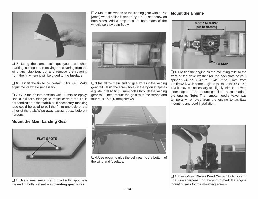
❏ 5. Using the same technique you used whenmarking, cutting and removing the covering from thewing and stabilizer, cut and remove the coveringfrom the fin where it will be glued to the fuselage.
❏ 6. Test fit the fin to be certain it fits well. Makeadjustments where necessary.
❏ 7. Glue the fin into position with 30-minute epoxy.Use a builder’s triangle to make certain the fin isperpendicular to the stabilizer. If necessary, maskingtape could be used to pull the fin to one side or theother of the stab. Wipe away excess epoxy before ithardens.
Mount the Main Landing Gear
❏ 1. Use a small metal file to grind a flat spot nearthe end of both prebent main landing gear wires.
❏ 2. Mount the wheels to the landing gear with a 1/8"[3mm] wheel collar fastened by a 6-32 set screw onboth sides. Add a drop of oil to both sides of thewheels so they spin freely.
❏ 3. Install the main landing gear wires in the landinggear rail. Using the screw holes in the nylon straps asa guide, drill 1/16" [1.6mm] holes through the landinggear rail. Then, mount the gear with the straps andfour #2 x 1/2" [13mm] screws.
❏ 4. Use epoxy to glue the belly pan to the bottom ofthe wing and fuselage.
Mount the Engine
❏ 1. Position the engine on the mounting rails so thefront of the drive washer (or the backplate of yourspinner) will be 3-5/8" to 3-3/4" [92 to 95mm] fromthe firewall. With some engines (such as the O. S. .40LA) it may be necessary to slightly trim the lower,inner edges of the mounting rails to accommodatethe engine. Note: The remote needle valve wastemporarily removed from the engine to facilitatemounting and cowl installation.
❏ 2. Use a Great Planes Dead Center™ Hole Locatoror a wire sharpened on the end to mark the enginemounting rails for the mounting screws.
- 14 -

❏ 3. Remove the engine. Drill 1/8" [3.2mm] holes atthe marks. Mount the engine to the mount with four4-40 x 1" [25mm] SHCS (socket head cap screws),#4 flat washers and lock washers and 4-40 blind nuts.
Mount the Cowl
❏ 1. Use a high-speed rotary tool with a cutting bit tocut slots in the aft end of the cowl to accommodatethe landing gear wires. Also cut an air inlet and airexit hole. The exit hole may be combined with theglow plug access hole.
❏ 2. Place the cowl on the fuselage and mount thespinner and propeller. Align the cowl with the spinner.There should be approximately 3/32" [2mm] betweenthe spinner and the cowl.
❏ 3. Holding the cowl in position, drill a 1/16" [1.6mm]hole through the cowl and fuselage for one of thecowl mounting screws. The hole should be about5/16" [8mm] from the aft edge of the cowl, placing itabout 1/4" behind the front edge of the fuselage side.Screw in a #2 x 1/4" [6mm] screw just enough to holdthe cowl, but do not tighten the screw.
❏ 4. One at a time while holding the cowl in position,drill a 1/16" [1.6mm] hole and insert a screw at theremaining three marks. Also drill a hole through bothsides of the cowl and fuselage approximately 3/4"[20mm] forward of the landing gear.
❏ 5. Remove the cowl. Enlarge the holes in the cowlonly with a 3/32" [2.4mm] drill. Test fit the cowl andmount it to the fuselage with six #2 x 1/4" [6mm] screws.
❏ 6. Remove the cowl screws and cowl. Add acouple of drops of thin CA to the screw holes–don’tadd too much CA, or you will seal the holes.
❏ 7. Cut the holes in the cowl for the muffler screws.This can be done by using a pencil to mark theheads of the screws on the inside of the cowl, andthen removing the cowl and cutting the holes.
- 15 -

❏ 8. Cut the hole for the muffler. Start by making thehole small, and then enlarge it until the muffler canbe mounted.
❏ 9. Mount the needle valve and cut an access holefor it in the cowl. Note: On the model featured in thismanual, the needle valve was mounted inverted. Ifmounting the needle sideways (as the engine isprovided from the factory), a slot must be cut in thecowl to accommodate the needle valve body.
❏ 10. Connect the fuel lines. The fuel tank includedwith this kit uses a three-line system. As shown in thesketch to the left, one line is the fuel pickup whichgoes to the carburetor (or to the remote needle as inthe case of the O.S. LA engines). The other line goesto the muffler for pressure (when the tank is full, fuelwill overflow through this line indicating that the tankis full). The third line is used for filling the tank. Thisline should be accessible from outside the fuselageand is to be closed after fueling. A Great Planesaluminum fuel line plug (GPMQ4166) was used toclose the fueling line. After the tank has been filled,the fueling line can be tucked back inside the cowl.
- 16 -

FINAL DETAILS
Mount the Canopy
❏ 1. Be certain that the flaps are centered when theelevators are centered. Also be certain that all thepushrods are connected and that the flaps andelevator are operating smoothly. Make anyadjustments necessary.
❏ 2. Use scissors to cut out the canopy on themolded-in cutlines. Start by cutting approximately1/8" [3mm] from the lines. Then, do a final cut righton the lines.
❏ 3. Mount the canopy to the fuselage with 1/4"[6mm] white striping tape. Use 1/16" [2mm] whitestriping tape to add the panel lines.
❏ 4. While you’ve got the 1/16" [2mm] striping tapeout, add the flap, elevator and rudder trim tab linesas well.
Apply the Decals
1. Use scissors or a sharp hobby knife to cut thedecals from the decal sheet. Where possible, roundthe corners so they are less likely to peel up duringcleaning and handling.
2. Be certain the model is clean. Prepare a dishpanor small bucket with a mixture of liquid dish soap andwarm water–about 1/2 teaspoon of soap per gallonof water. Submerse one of the decals in the solutionand peel off the paper backing. Note: Even thoughthe decals have a “sticky-back” and are not the watertransfer type, submersing them in soap & waterallows accurate positioning and reduces air bubblesunderneath.
3. Position the decal on the model where desired.Holding the decal down, use a paper towel to wipeaway most of the water.
4. Use a piece of soft balsa or something similar tosqueegee remaining water from under the decal.Apply the rest of the decals the same way.
GET THE MODEL READY TO FLY
Balance the Model (C.G.)
At this stage the model should be completely ready-to-fly with all of the components installed includingthe engine, muffler, propeller, spinner, landing gearand wheels.
❏ 1. If using a Great Planes C.G. Machine to balancethe model, set the rulers to 2-1/2" [65mm]. If notusing a C.G. Machine, use a fine-point felt-tip pen or
More than any other factor, the C.G. (balancepoint) can have the greatest effect on how amodel flies, and may determine whether or notyour first flight will be successful. If you value thismodel and wish to enjoy it for many flights, DONOT OVERLOOK THIS IMPORTANT PROCEDURE.A model that is not properly balanced will beunstable and possibly unflyable.
Do not permanently mount the canopy. Ifadjustments are ever required to the pushrods,the canopy may be removed to do so.
- 17 -

1/8" wide tape to accurately mark the recommendedC.G. (center of gravity, or “balance point”) on thebottom of the wing 2-1/2" [65mm] back from theleading edge on both sides of the belly pan.
❏ 2. Place the model on a Great Planes CGMachine, or lift it at the balance point you marked onboth sides of the fuselage. Note whether the nose ortail drops. If the tail drops, the model is “tail heavy”and weight must be added to the nose to balance. If,however, the nose drops (as will likely be the case),weight must be added to the tail to balance.
❏ 3. Add nose or tail weight to balance the model. Ifnose weight is required it may be added by using a“spinner weight” (GPMQ4645 for the 1 oz. [30g]weight, or GPMQ4646 for the 2 oz. [55g] weight) orGreat Planes (GPMQ4485) “stick-on” lead whichmay be added to the firewall (don’t attach weight tothe cowl–it is not intended to support weight). If tailweight is required it may be placed on the right sideof the fuselage (opposite the muffler) under thestabilizer. After the final amount of tail weight hasbeen determined (from several test flights) the coveringmay be cut from the lightening hole in the back of thefuselage and the lead permanently glued inside.
Note: Do not rely upon the adhesive on the back ofthe lead weight to permanently hold it in place. Overtime, fuel and exhaust residue may soften theadhesive and cause the weight to fall off. Use #2sheet metal screws, RTV silicone or epoxy topermanently hold the weight in place.
❏ 4. IMPORTANT: If you found it necessary to addany weight, recheck the C.G. after the weight hasbeen installed.
Wing Tip Weight
To begin, add 1 oz. [30g] of lead weight to the rightwing tip. This can be temporarily attached to thebottom of the wing with the self-adhesive foam tapeattached to the weight. After the final amount ofweight required has been determined (after test
flying), it can be permanently attached inside thewing tip with epoxy.
PREFLIGHT
Balance the Propellers
Carefully balance your propeller and sparepropellers before you fly. An unbalanced prop can bethe single most significant cause of vibration that candamage your model. Not only will engine mountingscrews and bolts loosen, possibly with disastrouseffect, but vibration can also cause your fuel to foam,which will, in turn, cause your engine to run hot or quit.
We use a Top Flite Precision Magnetic PropBalancer™ (TOPQ5700) in the workshop and keep aGreat Planes Fingertip Prop Balancer (GPMQ5000)in our flight box.
Engine Check
If the engine is new, follow the engine manufacturer’sinstructions to break-in the engine. After break-in,confirm that the engine runs reliably and smoothlyand maintains full power–indefinitely. After you runthe engine on the model, inspect the model closelyto make sure all screws remained tight, the hingesare secure and the prop is secure.
This is where the Nobler should balance for thefirst flights–especially for sport flying andbeginning aerobatics. After the first few flights,experienced modelers may wish to experimentby shifting the C.G. forward up to 1/4" [5mm] or byshifting the C.G. back, up to 1/4" [5mm] to changethe flying characteristics. If the C.G. is moved toofar forward (nose-heavy) response is slow andthe model becomes too difficult to flare forlanding. If the C.G. is moved too far aft (tail-heavy) the model becomes too unstable andover-responsive to control inputs. In any case,start at the recommended balance point.
- 18 -

Control Check
With the lines connected to the leadouts and yourassistant holding the model, operate the controls tomake sure they move smoothly. If any binding orhesitation is detected, inspect the model andeliminate the problem.
ENGINE SAFETY PRECAUTIONS
Keep all engine fuel in a safe place, away from highheat, sparks or flames, as fuel is very flammable. Donot smoke near the engine or fuel; and rememberthat engine exhaust gives off a great deal of deadlycarbon monoxide. Therefore, do not run the enginein a closed room or garage.
Get help from an experienced pilot when learning tooperate engines.
Use safety glasses when starting or running engines.
Do not run the engine in an area of loose gravel orsand; the propeller may throw such material in yourface or eyes.
Keep your face and body as well as all spectatorsaway from the plane of rotation of the propeller asyou start and run the engine.
Keep these items away from the prop: loose clothing,shirt sleeves, ties, scarfs, long hair or loose objectssuch as pencils or screwdrivers that may fall out ofshirt or jacket pockets into the prop.
Use a “chicken stick” or electric starter to start theengine. Do not use your fingers to flip the propeller.Make certain the glow plug clip or connector issecure so that it will not pop off or otherwise get intothe running propeller.
Make all engine adjustments from behind the rotatingpropeller.
The engine gets hot! Do not touch it during or rightafter operation. Make sure fuel lines are in goodcondition so fuel will not leak onto a hot engine,causing a fire.
To stop a glow engine, cut off the fuel supply byclosing off the fuel line or following the enginemanufacturer’s recommendations. Do not use hands,fingers or any other body part to try to stop theengine. To stop a gasoline powered engine an on/offswitch should be connected to the engine coil. Do notthrow anything into the propeller of a running engine.
AMA SAFETY CODE (excerpt)
Read and abide by the following Academy of ModelAeronautics Official Safety Code:
GENERAL1. I will not fly my model aircraft in sanctioned events,air shows, or model flying demonstrations until it hasbeen proven to be airworthy by having beenpreviously successfully flight tested.
3. Where established, I will abide by the safety rulesfor the flying site I use, and I will not willfully anddeliberately fly my models in a careless, recklessand/or dangerous manner.
5. I will not fly my model unless it is identified with myname and address or AMA number, on or in the model.
7. I will not operate models with pyrotechnics (anydevice that explodes, burns, or propels a projectile ofany kind).
8. I will not consume alcoholic beverages prior to, norduring, participation in any model operations.
9. Children under 6 years old are only allowed on theflight line as a pilot or while under flight instruction.
CONTROL LINE1. I will subject my complete control system(including safety thong, where applicable) to aninspection and pull test prior to flying. Pull test will bein accordance with the current CompetitionRegulations for applicable model category. Modelsnot fitting a specific category as detailed shall usethose pull test requirements for Control LinePrecision Aerobatics.
2. I will assure that my flying area is safely clear of allutility wires or poles.
3. I will assure that my flying area is safely clear of allnon-essential participants and spectators beforepermitting my engine to be started.
4. I will not fly a model closer than 50 feet [15m] toany electrical power line.
CHECK LIST
❏ 1. Make sure areas exposed to fuel or exhaustresidue have been fuelproofed (such as thefuel tank compartment, the landing gear rail,the back of the firewall and the front of thewing belly pan).
❏ 2. Check the C.G. according to the measurementsand procedure provided in the manual.
❏ 3. Use thread-locking compound on the set screwsin the wheel collars that hold on the wheels.
During the last few moments of preparation yourmind may be elsewhere anticipating theexcitement of the first flight. Because of this, youmay be more likely to overlook certain checksand procedures that should be performed beforethe model is flown. To help avoid this, a check listis provided to make sure these important areasare not overlooked. Many are covered in theinstruction manual, so where appropriate, referto the manual for complete instructions. Be sureto check the items off as they are completed(that’s why it’s called a check list!).
Failure to follow these safety precautionsmay result in severe injury to yourself and others.
- 19 -

❏ 4. Add a drop of oil to the axles so the wheels willturn freely.
❏ 5. Make sure all hinges are securely gluedin place.
❏ 6. Use thin CA to harden the holes in thefuselage for the cowl mounting screws.
❏ 7. Confirm that the flaps and elevators operatefreely and smoothly by pulling on the leadouts.
❏ 8. Make sure the fuel lines are connected andare not kinked.
❏ 9. Balance your propeller and spare propellers.❏ 10. Tighten the propeller nut and spinner.❏ 11. Place your name, address, AMA number and
telephone number on or inside your model.❏ 12. If you wish to photograph your model, do so
before the first flight.
FLYING
Flying Precautions
Preflight
Note: The Top Flite Nobler ARF is not a beginner’smodel. It is intended for beginning to advanced stuntpilots who have had some previous control lineexperience. If you are an inexperienced pilot seekthe assistance of a knowledgeable control line pilotwho can help you with your first flights.
Beginning stunt pilots should make their first flights incalm or low wind conditions. Stronger winds mayblow the model inward which will decrease linetension resulting in loss of control. If the lines ever dogo slack, quickly step back to tighten the lines andregain control. Of course, this is most likely tohappen, and should be expected, as the modelapproaches the upwind half of the circle.
Place the model and starting equipment where thewind will be behind the model when it is released fortakeoff.
For the first half-circle (during the brief period whenthe pilot has the least control before the model is “upto speed”) the wind will push the model outward tomaintain line tension.
Mark the center of the flying circle with paint, chalk ora suitable object (such as a shop towel) so you won’twander. This is especially important if the flying areais limited.
With your assistant holding the model, walk from themodel toward the handle in the center of the circlewhile using your fingers to keep the lines separated.This will ensure that the lines are not twisted and arefree to operate the controls.
Study these flying safety precautions beforeflying the Nobler ARF.1. Always inspect your equipment before each
flight. Make certain the lines, leadouts andhandle are in good condition. Make surethere are no kinks in the lines.
2. Fly only in unobstructed areas free fromtrees, shrubs and bushes, poles, stakes,parking barriers and fences.
3. Be aware of any spectators that may wanderinto the flying circle. If this is a possibility, haveyour assistant ready to perform crowdcontrol.
4. The model must NEVER be flown in thevicinity of high-tension lines or any otherelectrical lines.
5. Never fly when thunder storms or lightningare present.
6. Take any precautions necessary to insure thesafety of spectators, the model and property.
7. Never touch the engine during or soon afteroperation.
8. Keep clear of the rotating propeller and donot let assistants or spectators get in the arcof the propeller.
- 20 -
While the pilot is holding the lines, the assistantshould walk the model once around the circle to becertain the flight path is clear and to double-check thatthere are no obstructions that could snag the lines.
The pilot should double-check the operation of thecontrols by pulling and pushing on the handle andhaving the assistant signal what the controls aredoing (“up” and “down”).
Takeoff
Note: A fully cowled engine may run at a highertemperature than an un-cowled engine. Therefore,the fuel mixture should be richened so the engineruns at least 200 RPM below peak speed. By runningthe engine slightly rich, you will help prevent dead-stick landings caused by overheating. Traditionally,control line pilots intentionally set their engines richso that during vertical maneuvers, the engine will not“over lean,” thus causing overheating. Further, fullRPM is usually not desired for stunt flying.
When both the pilot and assistant are ready, themodel may be fueled and started. Once the engine isrunning and the model is ready to be released, theassistant should point the nose of the model slightlyaway from the circle. This will help keep the lines tautfor the first few feet until the model gets going.
Upon the pilot’s signal, the assistant may release themodel–never push the model forward as doing somay result in a crash.
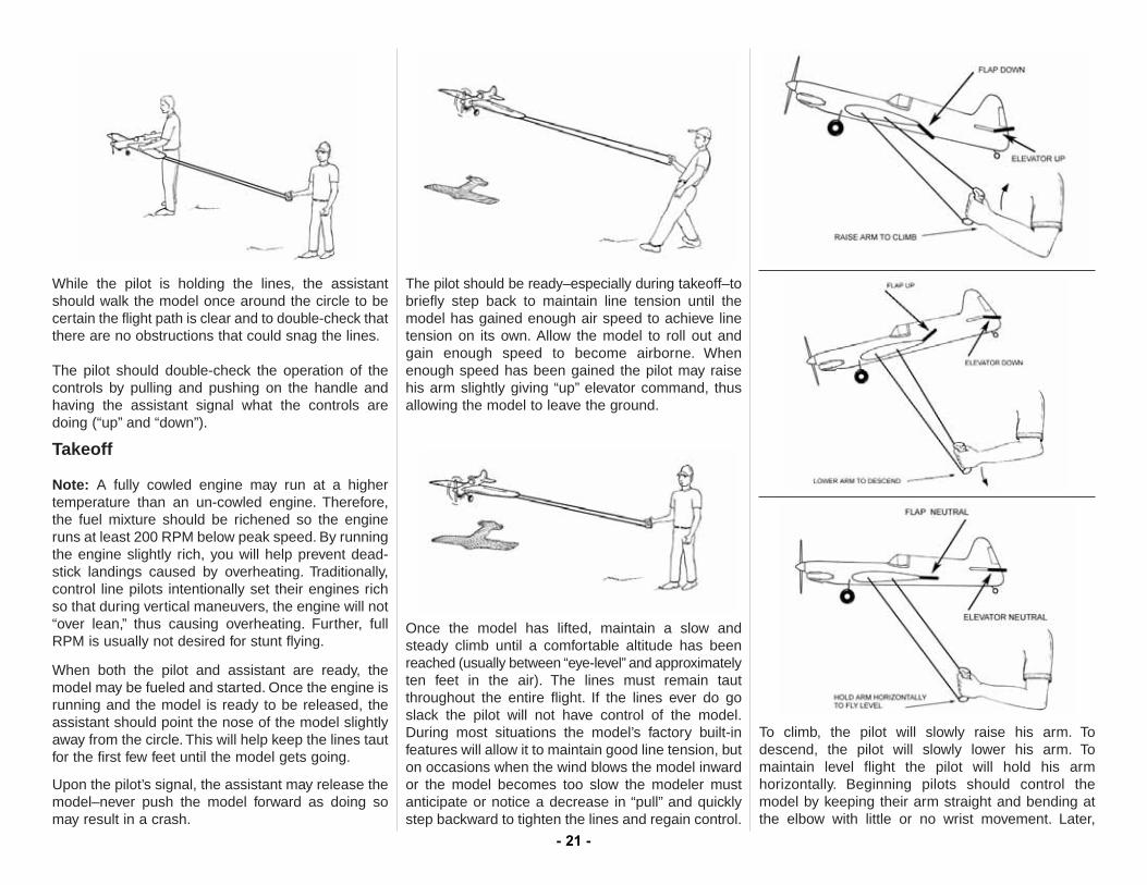
The pilot should be ready–especially during takeoff–tobriefly step back to maintain line tension until themodel has gained enough air speed to achieve linetension on its own. Allow the model to roll out andgain enough speed to become airborne. Whenenough speed has been gained the pilot may raisehis arm slightly giving “up” elevator command, thusallowing the model to leave the ground.
Once the model has lifted, maintain a slow andsteady climb until a comfortable altitude has beenreached (usually between “eye-level” and approximatelyten feet in the air). The lines must remain tautthroughout the entire flight. If the lines ever do goslack the pilot will not have control of the model.During most situations the model’s factory built-infeatures will allow it to maintain good line tension, buton occasions when the wind blows the model inwardor the model becomes too slow the modeler mustanticipate or notice a decrease in “pull” and quicklystep backward to tighten the lines and regain control.
To climb, the pilot will slowly raise his arm. Todescend, the pilot will slowly lower his arm. Tomaintain level flight the pilot will hold his armhorizontally. Beginning pilots should control themodel by keeping their arm straight and bending atthe elbow with little or no wrist movement. Later,
- 21 -

when they become more experienced, wristmovement may be increased to increase controlresponse. All control inputs should be smooth.Continue flying the model in a level attitude, gettingused to how the controls react and how the model“feels.” Do this until the engine runs out of fuel. Witha full tank of fuel the Nobler will fly for a little over fourminutes, but actual flight time depends on severalfactors, such as the engine size and brand, needlevalve setting, propeller size, fuel, atmosphericconditions, etc.
Landing
When the engine starts to sputter and/or speed up,this is an indication that the tank is nearly empty.Continue to fly the model in a level attitude until theengine finally quits. The same as any time the modelslows, the pilot should step back to keep the linestaut and maintain control. Allow the model todescend until it is about two feet off the ground.When the model has lost nearly all flying speed andis a foot or two from the ground the pilot should raisehis arm to keep the lines taut and apply full upelevator, allowing the model to gently touch down.
After the model has come to a stop the assistant mayretrieve the model and return it to the starting area.In doing so the lines should be kept taut so they donot become twisted or entangled.
Clean the model using paper towels and householdcleaner to wipe off exhaust residue. Inspect themodel thoroughly, looking for loose fasteners andsigns of damage or fatigue. Also make sure the prophas not been damaged. Perform any maintenancenecessary to prepare the model for the next flight.
At the end of the flying session any residual fuelshould be drained from the tank.
After you have become familiar with the way yourNobler flies and you are ready to begin performingstunts, seek the assistance of an experienced stuntpilot before attempting to learn new maneuvers onyour own. Almost any control line stunt maneuversare started with the model downwind from the pilot,i.e. wind on the pilots back. Consult the AMA ControlLine section for stunt maneuvers.
One final note about flying your model. Have a goalor flight plan in mind for every flight. This can belearning a new maneuver(s), improving amaneuver(s) you already know, or learning how themodel behaves in certain conditions (such as whentesting different propellers or fuel). This is notnecessarily to improve your skills (though it is nevera bad idea!), but more importantly so you do notsurprise yourself by impulsively attempting amaneuver and suddenly finding that you’ve run out oftime, altitude or airspeed. Every maneuver should bedeliberate, not impulsive. For example, if you’re goingto do a loop, check your altitude and mind the winddirection. A flight plan greatly reduces the chances ofcrashing your model just because of poor planningand impulsive moves. Remember to think!
Have a ball, keep the lines taut and always fly ina safe manner.
GOOD LUCK, GREAT FLYING, AND HAVE FUN!
O.S. Engines®
.40 LA-S Control Line Engine with Muffler(OSMG1440)
The O.S. 40 LA-S offers the proven power of LASeries R/C sport engines – but is engineered for thespecial requirements of control line flying, replacingthe carburetor with a venturi that keeps the enginerunning at a constant speed. A remotely mountedneedle valve keeps your hands safely distanced fromthe spinning prop during adjustments. An O-ringhelps seal the needle against fuel and air leaks,while heavy-duty webbing reinforces the blue-finish,one-piece crankcase in high-stress areas. IncludesE-3030 muffler, muffler mounting screws, #A3 glowplug, and 2-year warranty. Fuel with 10-20% nitroand 18% oil content recommended.
- 22 -

- 23 -
AMA STUNT MANEUVERS
Here are some of the AMA Stunt Maneuvers. Referto the AMA Rule Book for full descriptions.
Takeoff
Reverse Wingovers
Consecutive Inside Loops
Inverted Flight
Consecutive Outside Loops
Consecutive Inside Square Loops
Consecutive Outside Square Loops
Consecutive Inside Triangular Loops
Horizontal Eights

FLAP PUSHRODTEMPLATE
FLIGHT LOGDATE COMMENTS
Started ConstructionFinished ConstructionFirst FlightFirst LoopFirst Inverted FlightFirst Wingover