Embed Size (px)
Citation preview
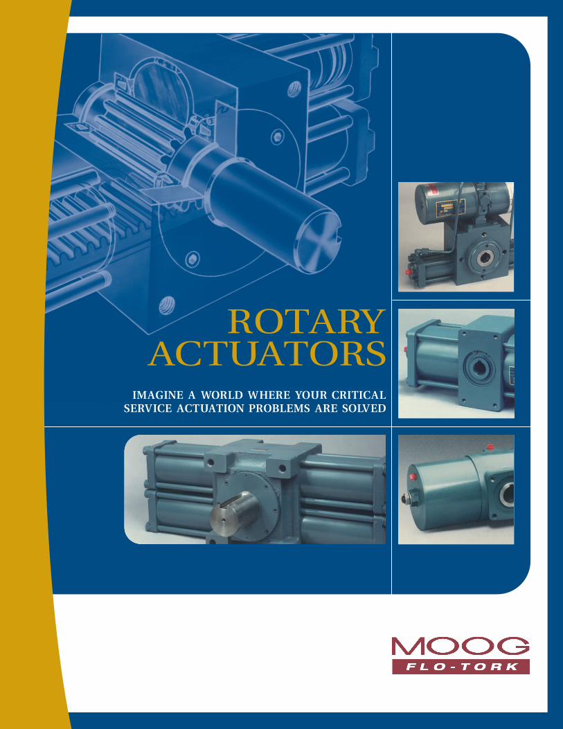
ROTARY ACTUATORS
IMAGINE A WORLD WHERE YOUR CRITICAL SERVICE ACTUATION PROBLEMS ARE SOLVED

2 M O O G F L O - T O R K
A SERIES SINGLE RACK, FULL FEATURE PNEUMATIC
ROTARY ACTUATORS
A SERIES OHIO OSCILLATORHIGH TORQUE, PNEUMATIC ROTARY ACTUATORS
STANDARD MODELS AND OPTIONS
P SERIESHIGH TORQUE, DOUBLE RACK PNEUMATIC
ROTARY ACTUATORS
HYDRAULIC SERIES HEAVY DUTY, SINGLE AND DOUBLE RACK
HYDRAULIC ROTARY ACTUATORS
HYDRAULIC SERIES OHIO OSCILLATORHEAVY DUTY, SINGLE AND DOUBLE RACK
HYDRAULIC ROTARY ACTUATORS
M O O G F L O - T O R K 3
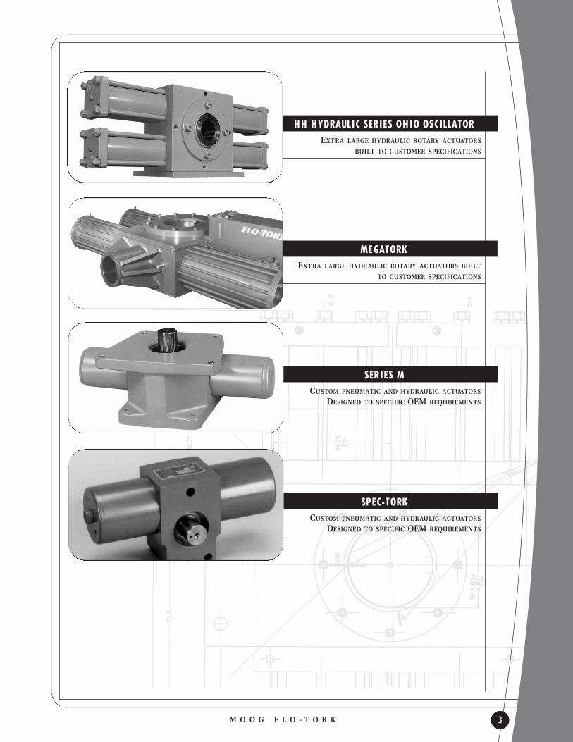
HH HYDRAULIC SERIES OHIO OSCILLATOREXTRA LARGE HYDRAULIC ROTARY ACTUATORS
BUILT TO CUSTOMER SPECIFICATIONS
MEGATORKEXTRA LARGE HYDRAULIC ROTARY ACTUATORS BUILT
TO CUSTOMER SPECIFICATIONS
SERIES M CUSTOM PNEUMATIC AND HYDRAULIC ACTUATORS
DESIGNED TO SPECIFIC OEM REQUIREMENTS
SPEC-TORK CUSTOM PNEUMATIC AND HYDRAULIC ACTUATORS
DESIGNED TO SPECIFIC OEM REQUIREMENTS

D E S C R I P T I O N P A G E
LINE SUMMARY 3
TABLE OF CONTENTS 4-5
A SERIES PNEUMATIC-FEATURES AND OPTIONS 6
A SERIES PNEUMATIC-ENVELOPE DIMENSIONS 7
A SERIES PNEUMATIC-TYPICAL PERFORMANCE 8
A SERIES PNEUMATIC-END CAP OPTIONS 9
A SERIES PNEUMATIC-MOUNTING OPTIONS 10
A SERIES PNEUMATIC-SHAFT OPTIONS 11
A SERIES PNEUMATIC-POSITION IDENTIFICATION AND PORTING 12
A SERIES PNEUMATIC-HOW TO ORDER 13
A SERIES OHIO OSCILLATOR PNEUMATIC-FEATURES AND OPTIONS 14
A SERIES OHIO OSCILLATOR PNEUMATIC-ENVELOPE DIMENSIONS 15
A SERIES OHIO OSCILLATOR PNEUMATIC-TYPICAL PERFORMANCE 16
A SERIES OHIO OSCILLATOR PNEUMATIC-END CAP OPTIONS 17
A SERIES OHIO OSCILLATOR PNEUMATIC-MOUNTING OPTIONS 18
A SERIES OHIO OSCILLATOR PNEUMATIC-SHAFT OPTIONS 19
A SERIES OHIO OSCILLATOR PNEUMATIC-POSITION IDENTIFICATION AND PORTING 20
A SERIES OHIO OSCILLATOR PNEUMATIC-HOW TO ORDER 21
P SERIES PNEUMATIC-FEATURES AND OPTIONS 22
P SERIES PNEUMATIC-ENVELOPE DIMENSIONS 23
P SERIES PNEUMATIC-TYPICAL PERFORMANCE 24
P SERIES PNEUMATIC-HOW TO ORDER 25
HYDRAULIC SERIES-FEATURES AND OPTIONS 26
HYDRAULIC SERIES-ENVELOPE DIMENSIONS 27
HYDRAULIC SERIES-TYPICAL PERFORMANCE 28
HYDRAULIC SERIES-END CAP OPTIONS 29
HYDRAULIC SERIES-MOUNTING OPTIONS 30
HYDRAULIC SERIES-SHAFT OPTIONS 31
HYDRAULIC SERIES-POSITION IDENTIFICATION AND PORTING 32
HYDRAULIC SERIES-HOW TO ORDER 33
TABLE OF CONTENTS
4
T A B L E O F C O N T E N T S
M O O G F L O - T O R K T A B L E O F C O N T E N T S

TABLE OF CONTENTS
M O O G F L O - T O R KT A B L E O F C O N T E N T S 5
T A B L E O F C O N T E N T S
D E S C R I P T I O N P A G E
HYDRAULIC SERIES OHIO OSCILLATOR-FEATURES AND OPTIONS 34
HYDRAULIC SERIES OHIO OSCILLATOR-ENVELOPE DIMENSIONS 35
HYDRAULIC SERIES OHIO OSCILLATOR-TYPICAL PERFORMANCE 36
HYDRAULIC SERIES OHIO OSCILLATOR-END CAP OPTIONS 36-37
HYDRAULIC SERIES OHIO OSCILLATOR-POSITION IDENTIFICATION AND PORTING 38
HYDRAULIC SERIES OHIO OSCILLATOR-SHAFT OPTIONS 39
HYDRAULIC SERIES OHIO OSCILLATOR-MOUNTING OPTIONS 40
HYDRAULIC SERIES OHIO OSCILLATOR-HOW TO ORDER 41
HYDRAULIC HEAVY DUTY SERIES OHIO OSCILLATOR-FEATURES AND OPTIONS 42
HYDRAULIC HEAVY DUTY SERIES OHIO OSCILLATOR-ENVELOPE DIMENSIONS 43
HYDRAULIC SERIES HEAVY DUTY OHIO OSCILLATOR-TYPICAL PERFORMANCE 44
MEGATORK SERIES OHIO OSCILLATOR 45
MEGATORK SERIES-FEATURES AND OPTIONS 46
MEGATORK SERIES-APPLICATION 47
MEGATORK SERIES-TYPICAL PERFORMANCE 48
SPEC-TORK SERIES-ROTARY ACTUATOR DESIGNS FOR SPECIAL APPLICATIONS 49
DIMENSIONS-CUSHIONS AND STROKE ADJUSTORS 50
UNIT WEIGHTS 51
DIMENSIONS-CUSHIONS AND STROKE ADJUSTORS 52
UNIT MASS 53
APPLICATION EXAMPLES, ROTARY MOTION 54
QUANTITIES AND FORMULAS FOR ROTARY MOTION 55
MOMENT OF INERTIA AND CUSHION DATA 56
CUSHION CAPACITY AND SIZING 57
LINEAR DRIVE 58
FT HYDRAOLIC 59
OO HYDRAOLIC 60
APPLICATION SPECIFICATION GUIDE 61
WARRANTY 62
NOTES 63

A SERIES
6
P N E U M A T I C R O T A R Y A C T U A T O R S
M O O G F L O - T O R K A S E R I E S
Bearingsl PRE-LUBRICATED - BRONZE OR ROLLER TYPEl HIGH LOAD CAPACITY, LOW FRICTION
Housings l HIGH STRENGTH ALUMINUM OR DUCTILE IRONl OPTIONAL MOUNTING SURFACES
Pinion Shaft l WORK HARDENED STEELl RUGGED ONE-PIECECONSTRUCTION
l SINGLE TOOTHLOAD CAPACITY
Pistons l PATENTEDFLOATING DESIGN
l BLOCK V SEALSGearing l LARGE RACK BEARING SUPPORT AREAl SINGLE TOOTH LOAD CAPACITY
Tie Rods l PRE-STRESSED STEEL ALLOYl PRECISION ROLLED THREADS
Gear Chamber l LIFETIME LUBRICATEDl ELASTOMER SEALED
Cylinder l HEAVY WALLTUBING
l PRECISIONHONED BORES
End Capsl CORROSIONRESISTANTALUMINUM
l OPTIONALCUSHIONS & ADJUSTORS
A1 0 0 0 T I E R O D D E S I G N S H O W N
D E S I G N F E A T U R E S
l HIGH PRESSURE - 8.62 BAR MAX.
l TORQUE RANGE - 11.29 TO 1130 NM @ 7 BAR
l STANDARD ROTATIONS - 94, 184, 364 DEGREES
l BSPP PORTS
l RACK & PINION - HIGH MECHANICAL EFFICIENCY
l ZERO LEAKAGE - HIGH VOLUMETRIC EFFICIENCY
l PRECISION BEARINGS - HIGH LOAD CAPACITY, LOW FRICTION
l PISTON SEALS - BLOCK-V
l GEARING - SINGLE TOOTH FULL LOAD CAPACITY
l OPERATING TEMPERATURE - -180 TO 930 C
l A100 & A500 - EXTRUDED ALUMINUM HOUSING-HARD COAT ANODIZED
S T A N D A R D O P T I O N S
l ADJUSTABLE CUSHIONS
l STROKE ADJUSTORS
l END PORTS OR SIDE PORTS
l MOUNTING VARIATIONS
l SHAFTING VARIATIONS
l CUSTOMER SPECIFIED ROTATIONS
l CUSTOM SEALING ARRANGEMENTS
l SPECIAL COATINGS

A B C E F G H J K MODEL ROTATIONNUMBER DEGREES mm mm mm mm mm BSPP mm mm
94º 111.00 M6 X 112.66 3.18
A100 184º 140.97 63.50 63.50 X G 1/4” - 19 44.45 44.45 X12.70 19.05
364º 200.66 8DP94º 180.59 M6 X 1
22.23 4.76A500 184º 244.60 92.20 92.20 X G 1/4” - 19 69.85 69.85 X
22.25 92.08364º 372.11 13DP94º 256.03 M8 X 1.25
25.40 6.35A1000 184º 335.79 120.65 146.05† X G 3/8” - 19 63.50 127.00 X
25.45 120.65364º 468.38 16DP94º 354.33 M12 X 1.75
44.45 9.53A4000 184º 481.58 184.15 177.80† X G 3/8” - 19 95.25 95.25 X
44.50 88.90364º 739.39 19DP94º 470.92 M16 X 2
57.15 12.70A10000 184º 649.48 238.25 234.95† X G 1/2” - 19 127.00 127.00 X
57.20 101.60364º 1008.38 25DP
A SERIES
M O O G F L O - T O R KA S E R I E S 7
E N V E L O P E D I M E N S I O N S
* K e y w ay e n g a g e m e n t i s m e a s u r e d f r o m t h e f r o n t f a c e .† D i m e n s i o n s s h o w n a r e “A s C a s t ” D i m e n s i o n s .
M O D E L S A1 0 0 A N D A 5 0 0
M O D E L A1 0 0 0
M O D E L S A 4 0 0 0 A N D A1 0 0 0 0

BAR 0 1.7 3.4 5.2 6.9 8.6 BAR 0 1.7 3.4 5.2 6.9 8.6
TORQUENM
73
68
62
56
51
45
40
34
28
23
17
11
6
0
A SERIES
8
T Y P I C A L P E R F O R M A N C E
M O O G F L O - T O R K A S E R I E S
MODEL TORQUE*NUMBER FACTOR 2.76 4.14 6.89 8.62
A100 1.64 4.5 6.8 11.3 14.1
A500 8.19 22.6 33.9 56.5 70.6
A1000 16.39 45.2 67.8 113.0 141.2
A4000 65.55 180.8 271.2 451.9 564.9
A10000 163.87 451.9 677.9 1129.8 1412.3
O U T P U T T O R Q U E ( N m ) A T VA R I O U S P R E S S U R E S * ( B A R )
MODEL DISPLACEMENT*NUMBER FACTOR 94º 184º 364º
A100 0.0003 0.0282 0.0552 0.1092
A500 0.002 0.188 0.368 0.728
A1000 0.004 0.376 0.736 1.456
A4000 0.013 1.222 2.392 4.732
A10000 0.032 3.008 5.888 11.648
D I S P L A C E M E N T ( L ) P E R S T R O K E *
* O u t p u t t o r q u e ( N m) = To r q u e Fa c t o r x O p e r a t i n g P r e s s u r e ( b a r) .E x a m p l e : M o d e l A 1 0 0 0 @ 7 b a r d e l i v e r s ( 1 6 . 3 9 x 6 . 8 9 = ) 1 1 3 N m o f t o r q u e .
* D i s p l a c e m e n t ( L) = D i s p l a c e m e n t Fa c t o r x R o t a t i o n a l A r c ( d e g r e e s) . E X A M P L E : A 5 0 0 @ 1 8 4 º s w e e p s ( . 0 0 2 x 1 8 4 ) = . 3 6 8 L
A1 0 0 & A 5 0 0
T O R Q U E O U T P U TV S .
P R E S S U R E
TORQUENM
1,469
1,356
1,243
1,130
1,017
904
791
678
565
452
339
226
113
0
A1 0 0 0 T O A1 0 0 0 0
T O R Q U E O U T P U TV S .
P R E S S U R E
A10000
A4000
A1000
A500
A100
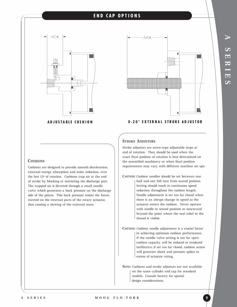
CUSHIONSCushions are designed to provide smooth deceleration,
external energy absorption and noise reduction, over
the last 15º of rotation. Cushions trap air at the end
of stroke by blocking or restricting the discharge port.
The trapped air is diverted through a small needle
valve which generates a back pressure on the discharge
side of the piston. This back pressure resists the forces
exerted on the internal parts of the rotary actuator,
thus causing a slowing of the external mass.
A SERIES
M O O G F L O - T O R KA S E R I E S 9
E N D C A P O P T I O N S
0 - 2 0 º E X T E R N A L S T R O K E A D J U S T O RA D J U S T A B L E C U S H I O N
STROKE ADJUSTORSStroke adjustors are screw-type adjustable stops at
end of rotation. They should be used when the
exact final position of rotation is best determined on
the assembled machinery or when final position
requ irements may vary with different machine set ups.
CAUTION: Cushion needles should be set between one
half and one full turn from seated position.
Setting should result in continuous speed
reduction throughout the cushion length.
Needle adjustment is set too far closed when
there is an abrupt change in speed as the
actuator enters the cushion. Never operate
with needle in seated position or unscrewed
beyond the point where the seal relief in the
thread is visible.
CAUTION: Cushion needle adjustment is a crucial factor
in achieving optimum cushion performance.
If the needle valve setting is too far open
cushion capacity will be reduced or rendered
ineffective; if set too far closed, cushion action
will generate shock and pressure spikes in
excess of actuator rating.
NOTE: Cushions and stroke adjustors are not available
on the same cylinder end cap for standard
models. Consult factory for special
design considerations.
A SERIES
10
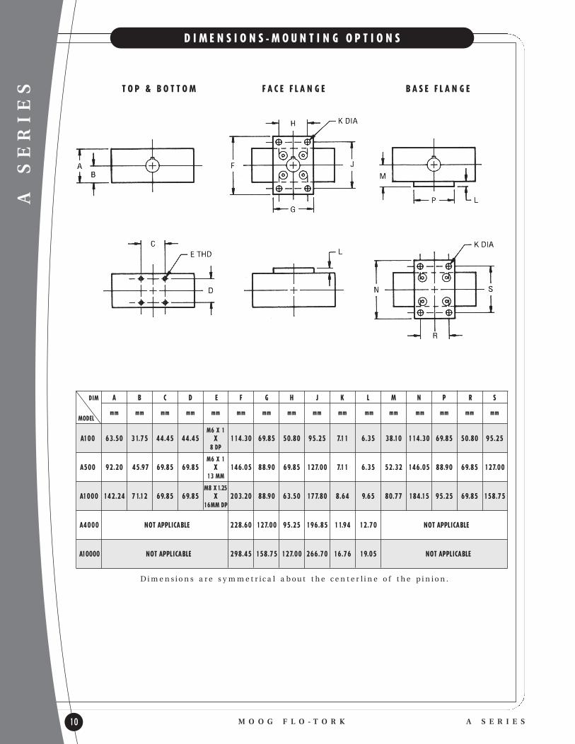
D I M E N S I O N S - M O U N T I N G O P T I O N S
M O O G F L O - T O R K A S E R I E S
T O P & B O T T O M F A C E F L A N G E B A S E F L A N G E
DIM A B C D E F G H J K L M N P R S
MODELmm mm mm mm mm mm mm mm mm mm mm mm mm mm mm mm
M6 X 1A100 63.50 31.75 44.45 44.45 X 114.30 69.85 50.80 95.25 7.11 6.35 38.10 114.30 69.85 50.80 95.25
8 DP
M6 X 1A500 92.20 45.97 69.85 69.85 X 146.05 88.90 69.85 127.00 7.11 6.35 52.32 146.05 88.90 69.85 127.00
13 MM
M8 X1.25A1000 142.24 71.12 69.85 69.85 X 203.20 88.90 63.50 177.80 8.64 9.65 80.77 184.15 95.25 69.85 158.75
16MM DP
A4000 NOT APPLICABLE 228.60 127.00 95.25 196.85 11.94 12.70 NOT APPLICABLE
A10000 NOT APPLICABLE 298.45 158.75 127.00 266.70 16.76 19.05 NOT APPLICABLE
D i m e n s i o n s a r e s y m m e t r i c a l a b o u t t h e c e n t e r l i n e o f t h e p i n i o n .
A SERIES
M O O G F L O - T O R KA S E R I E S 11
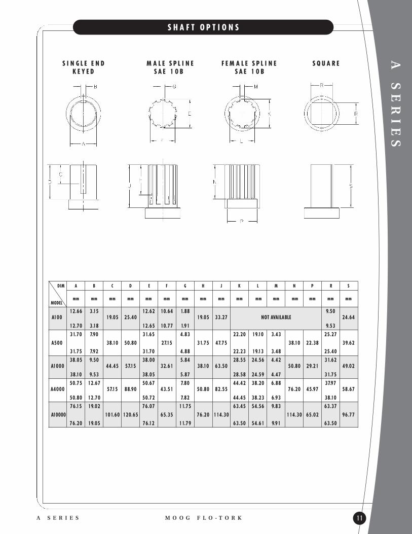
S H A F T O P T I O N S
S I N G L E E N D M A L E S P L I N E F E M A L E S P L I N E S Q U A R EK E Y E D S A E 1 0 B S A E 1 0 B
DIM A B C D E F G H J K L M N P R S
MODELmm mm mm mm mm mm mm mm mm mm mm mm mm mm mm mm
12.66 3.15 12.62 10.64 1.88 9.50A100 19.05 25.40 19.05 33.27 NOT AVAILABLE 24.64
12.70 3.18 12.65 10.77 1.91 9.53
31.70 7.90 31.65 4.83 22.20 19.10 3.43 25.27
A500 38.10 50.80 27.15 31.75 47.75 38.10 22.38 39.62
31.75 7.92 31.70 4.88 22.23 19.13 3.48 25.40
38.05 9.50 38.00 5.84 28.55 24.56 4.42 31.62A1000 44.45 57.15 32.61 38.10 63.50 50.80 29.21 49.02
38.10 9.53 38.05 5.87 28.58 24.59 4.47 31.75
50.75 12.67 50.67 7.80 44.42 38.20 6.88 37.97A4000 57.15 88.90 43.51 50.80 82.55 76.20 45.97 58.67
50.80 12.70 50.72 7.82 44.45 38.23 6.93 38.10
76.15 19.02 76.07 11.75 63.45 54.56 9.83 63.37
A10000 101.60 120.65 65.35 76.20 114.30 114.30 65.02 96.77
76.20 19.05 76.12 11.79 63.50 54.61 9.91 63.50

CONSULTFACTORY
A SERIES
12
P O S I T I O N I D E N T I F I C A T I O N P O R T I N G
M O O G F L O - T O R K A S E R I E S
The following identification codes are used to specify
the location of cushions, cushion adjustments, side
ports, mountings, or other special requ irements.
SURFACE IDENTIFICATION
MS1 - Front surface or face - bearing cap side
MS2 - Bottom surface - opposite keyway when actuator is at mid-rotation (applies to standard keyway location only). Available on models A100, A500 and A1000.
MS3 - Back surface - opposite of bearing cap side
MS4 - Top surface - opposite bottom surface. Available on models A100, A500 and A1000.
CYLINDER END IDENTIFICATIONCylinder ends are numerically identified as shown
below. The left cylinder end is No. 1 and the right
cylinder end is No. 2 when looking at the front
face with the keyway at 12 o’clock and the rotary
actuator at mid-rotation.
PORTS - Air Rotary Actuators
Standard and optional port configuration for FLO-TORK pneumatic rotary actuators.
RECOMMENDEDSTANDARD* TUBE SIZE WHEN EXTERNA L STROKE
MODEL BSPP PORT O.D. (mm) ADJUSTORS A RE PROVIDED SIDE PORTS
A100 G 1/4” - 19 8 G 1/8-28
A500 G 1/4” - 19 8
A1000 G 3/8” - 19 12
A4000 G 3/8” - 19 12
A10000 G 1/2” - 14 16
PORTING IS RELOCATEDTO ENDCAP FACE ABOVE
ADJUSTOR PORT. SIZING IS AS SHOWN FOR
STANDARD PORTS.
* C o n s u l t f a c t o r y f o r s p e c i a l p o r t i n g r e q u i r e m e n t s .

A SERIES
M O O G F L O - T O R KA S E R I E S 13
H O W T O O R D E R
A SERIESTORQUEOUTPUT
MODEL AT 7 BAR
A100 11.3 Nm A500 56.5 Nm
A1000 113 NmA4000 452 Nm
A10000 1130 Nm
ROTATIONAL ARC94 — 94º
184 — 184º -0/+2º 364 — 364º
–––- — Other specify
CUSHIONSOO — Omit CL — CCW stroke, right end cap CR — CW stroke, left end cap CB — Cushioned both directions X — Special cushions*
NOTE: Cushion needle adjustment faces front in standard assembly. Refer to mounting surface call out to specify other orientation.
EXAMPLE: Two cushions, back facing CB3.
STROKE ADJUSTORSOO — Omit AL — CCW stroke, right end capAR — CW stroke, left end cap AB — Adjustors both directions X — Special adjustors*
CUSHIONS & STROKE ADJUSTORSNot Available on Same End
PORTINGEB — End ports, BSPP SB — Side ports, BSPP X — Special porting*
NOTE: Side ports not available when cushions are specified.
A1000 - 184 - CB - EB - MS1 - RKH - N -
SPECIAL MODIFICATIONSXT — Special timing XB — Special bearings XM — Special materials XC — Special coatings X — Special features*
MOUNTINGMS1 — Front face mount (bearing cap side)-standard MS2 — Bottom face mount MS3 — Back face mount MS4 — Top face mount
X — Special configuration*
Multiple mounting surfaces are designated by combiningnumerals (i.e., front and back is MS13). MS2 and MS4 mountings are available on models A100, A500 and A1000 only.
*NOTE: The letter ‘X’ appearing as a suffix in the model code requ ires additional information or serial number for complete model identification.
SHAFT CONFIGURATIONRKS — Single end, keyed (standard on A100) SBS — Single end, external spline SQS — Single end, square
RKD — Double end, both keyedSBH — Hollow, internal spline RKH — Hollow keyed (standard on A500 up)
X — Special shaft*.
SEALSN — Nitrile (Buna-N)-standard
NL — Nitrile (Buna-N)-Lip SealsF — Fluoroelastomer (Viton)X — Special seal*

A SERIES OHIO OSCILLATOR
14
P N E U M A T I C R O T A R Y A C T U A T O R S
M O O G F L O - T O R K A S E R I E S
A - 1 0 0 0 T I E R O D D E S I G N S H O W N
D E S I G N F E A T U R E S
l HIGH PRESSURE AIR - 17 BAR MAX.
l LOW PRESSURE HYDRAULIC - 17 BAR MAX.
l TORQUE RANGE - 23 TO 1921 NM @ 7 BAR
l STANDARD ROTATIONS - 100, 190, 280, 370 DEGREES
l ZERO LEAKAGE - HIGH VOLUMETRIC EFFICIENCY
l RACK & PINION - HIGH MECHANICAL EFFICIENCY
l TAPERED ROLLER BEARING - HIGH EXTERNALLOAD CAPACITY
l PISTON SEALS - PRE-LOADED LIP SEALS
l GEARING - SINGLE TOOTH FULL LOAD CAPACITY
l THRU SHAFT - POSITION INSTRUMENTATION DRIVE
l OPERATING TEMPERATURE - -180 TO 930 C
S T A N D A R D O P T I O N S
l ADJUSTABLE CUSHIONS
l STROKE ADJUSTORS
l COMBINED CUSHINON AND STROKE ADJUSTOR
l BSPP
l ALTERNATIVE MOUNTING ARRANGEMENTS
l ALTERNATIVE SHAFT CONFIGURATIONS
l CUSTOM ROTATIONAL ARCS
l SIDE PORTED END CAPS
l SPECIAL SEALS
l AIR BLEEDS (FOR HYDRAULIC SERVICES)
A 6 . 2 T H R U A 2 5 0 .1 0 S H O W N
Gearing l DUAL RACK DESIGN
l LARGE RACK BEARING SUPPORT AREA
l HARD COATED ALUMINUM RACK
l SINGLE TOOTH LOAD CAPACITY
End Caps l ANODIZED ALUMINUM
l OPTIONAL ADJUSTORS
Housings l HIGH STRENGTH ALUMINUM
l HARD COAT ANODIZEDGear Chamber l LIFE TIME LUBRICATEDl ELASTOMER SEALED
Pinion Shaft l WORK HARDENED STEEL
l RUGGED ONE-PIECE CONSTRUCTIONl SINGLE TOOTH LOAD CAPACITY
Bearings l PRE-LUBRICATEDl HIGH LOAD CAPACITY
l LOW FRICTION

A SERIES OHIO OSCILLATOR
M O O G F L O - T O R KA S E R I E S 15
E N V E L O P E D I M E N S I O N S
A B C D E F G H J K L M N P Q R S T U
MODEL ROTATIONNUMBER DEGREE mm mm mm mm mm mm mm mm mm mm mm mm mm mm mm mm mm mm
100 285.24190 317.50
A6.2 M10 X280 407.16 1.5370 436.88 76.03 76.03 25.35 6.35 4.75 22.23
101.60 127.00 101.60 9.53 120.65 X 31.75 X 1/4-19 85.85 57.15 50.80 X 44.45100 290.83 76.20 76.20 25.40 25.4 3.18 22.30 BSPP190 320.80 13MM
A6.3 DP280 410.21370 440.18
100 336.55190 376.43
A19.3 280 499.11 M14 X
2370 542.04 88.77 88.77 31.70 6.35 6.35 25.40 1/4-19
120.65 146.05 114.30 11.68 144.02 X 38.86 X 82.55 69.85 41.28 X 50.80100 339.09 88.90 88.90 31.75 31.75 12.19 25.50 BSPP190 378.97 13MM
A19.4 DP280 501.40370 546.10
100 428.50190 484.38
A67.4 280 656.59 3/8-19 M16 X 2370 712.47 126.87 126.87 50.75 12.7 9.53 44.48 BSPP
203.20 203.20 165.10 15.75 232.41 X 69.85 X 114.30 101.60 57.15 X 69.85100 440.44 127.00 127.00 50.80 50.8 6.35 44.53 1/2-14190 496.32 BSPP 22MM
A67.6 DP280 670.05370 725.93
100 653.03190 835.41
A250.6 M20 X 280 1075.18 2.5370 1251.81 215.65 215.65 76.15 19.05 19.05 76.23
254.00 330.20 228.60 24.89 303.78 X 76.20 X 3/4-14 203.20 165.10 101.60 X 127.00100 653.03 215.90 215.90 76.17 50.8 12.7 76.28 BSPP190 835.41 29MM
A250.8 DP280 1075.18370 1257.81
100 762.00 M20 X190 866.65 215.65 215.65 76.15 19.05 19.05 76.23 2.5
A250.10 279.40 355.60 228.60 24.89 303.78 X 76.20 X 1-11 226.70 165.10 165.10 X 127.00280 1184.15 215.90 215.90 76.17 50.8 12.7 76.28 BSPP 29MM370 1336.55 DP
N O T E : Ta b u l a t e d d i m e n s i o n s a r e f o r b a s e m o d e l , s t a n d a r d c o n f i g u r a t i o n . T h e s e l e c t i o n o f o p t i o n s m ay a l t e r e n v e l o p e d i m e n s i o n .
R e f e r t o o p t i o n s s e c t i o n o r c o n s u l t f a c t o r y f o r a d d i t i o n a l i n f o r m a t i o n .* D i m e n s i o n D i s a s c a s t .
A SERIES OHIO OSCILLATOR
16
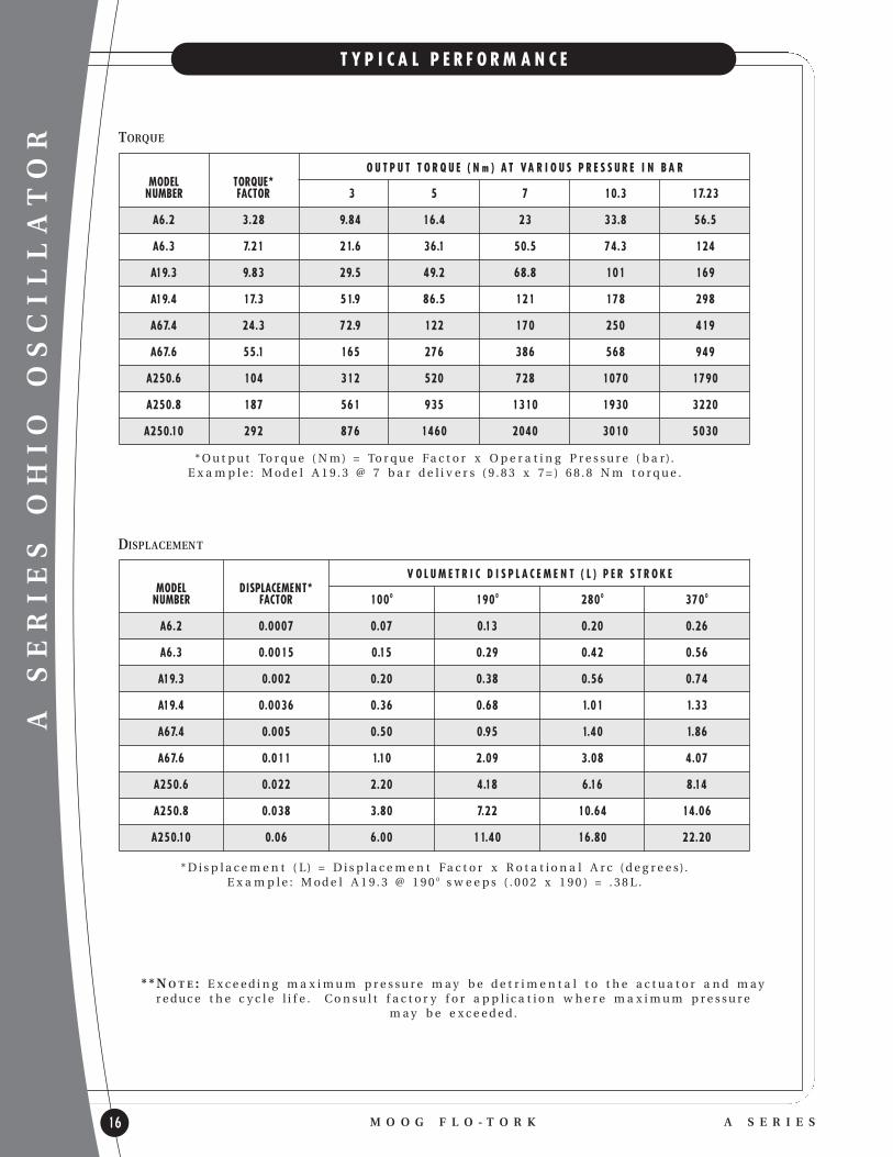
T Y P I C A L P E R F O R M A N C E
M O O G F L O - T O R K A S E R I E S
* O u t p u t To r q u e ( N m) = To r q u e Fa c t o r x O p e r a t i n g P r e s s u r e ( b a r) . E x a m p l e : M o d e l A 1 9 . 3 @ 7 b a r d e l i v e r s ( 9 . 8 3 x 7 = ) 6 8 . 8 N m t o r q u e .
DISPLACEMENT
TORQUE
* * N O T E : E x c e e d i n g m a x i m u m p r e s s u r e m ay b e d e t r i m e n t a l t o t h e a c t u a t o r a n d m ayr e d u c e t h e c y c l e l i f e . C o n s u l t f a c t o r y f o r a p p l i c a t i o n w h e r e m a x i m u m p r e s s u r e
m ay b e e x c e e d e d .
MODEL TORQUE*NUMBER FACTOR 3 5 7 10.3 17.23
A6.2 3.28 9.84 16.4 23 33.8 56.5
A6.3 7.21 21.6 36.1 50.5 74.3 124
A19.3 9.83 29.5 49.2 68.8 101 169
A19.4 17.3 51.9 86.5 121 178 298
A67.4 24.3 72.9 122 170 250 419
A67.6 55.1 165 276 386 568 949
A250.6 104 312 520 728 1070 1790
A250.8 187 561 935 1310 1930 3220
A250.10 292 876 1460 2040 3010 5030
O U T P U T T O R Q U E ( N m ) A T VA R I O U S P R E S S U R E I N B A R
MODEL DISPLACEMENT*NUMBER FACTOR 1000 1900 2800 3700
A6.2 0.0007 0.07 0.13 0.20 0.26
A6.3 0.0015 0.15 0.29 0.42 0.56
A19.3 0.002 0.20 0.38 0.56 0.74
A19.4 0.0036 0.36 0.68 1.01 1.33
A67.4 0.005 0.50 0.95 1.40 1.86
A67.6 0.011 1.10 2.09 3.08 4.07
A250.6 0.022 2.20 4.18 6.16 8.14
A250.8 0.038 3.80 7.22 10.64 14.06
A250.10 0.06 6.00 11.40 16.80 22.20
V O L U M E T R I C D I S P L A C E M E N T ( L ) P E R S T R O K E
* D i s p l a c e m e n t ( L) = D i s p l a c e m e n t Fa c t o r x R o t a t i o n a l A r c ( d e g r e e s) .E x a m p l e : M o d e l A 1 9 . 3 @ 1 9 0 0 s w e e p s ( . 0 0 2 x 1 9 0 ) = . 3 8 L .

A SERIES OHIO OSCILLATOR
M O O G F L O - T O R KS E R I E S A 17
E N D C A P S
CUSHIONSCushions are designed to protect the actuator from
damaging impact at the end of rotation. When
properly sized and adjusted, cushions may also
provide smooth deceleration, external energy
absorption and noise reduction.
Cushions trap flu id at the end of stroke by blocking
or restricting the discharge port. The trapped flu id is
diverted through a small needle valve which generates
a back pressure on the discharge side of the piston.
The back pressure resists the forces exerted on the
rack by the propelling action of the actuator and the
slowing of external mass which imparts engery into
the actuator through the shaft. A check valve is
included to bypass the cushion action at the start of
rotation in the reverse direction.
STROKE ADJUSTORSStroke adjustors are screw-type adjustable stops at
end of rotation. They should be used when the
exact final position of rotation is best determined on
the assembled machinery or when final position
requ irements may vary with different machine set ups.
STROKE ADJUSTORS & ADJUSTABLE CUSHIONAdjustable cushion and stroke adjustors are combined
as a single end of stroke option.
The Ohio Oscillator design moves the cushion
engagement position along with the end of stroke
adjustment so the full engagement length of the
cushion is retained at any stroke adjustment setting.
CAUTION: Cushion needles should be set between one
half and one full turn from seated position.
Setting should result in continuous speed
reduction throughout the cushion length.
Needle adjustment is set too far closed when
there is an abrupt change in speed as the
actuator enters the cushion. Never operate
with needle in seated position or unscrewed
beyond the point where the seal relief in the
thread is visible.
NOTE: Cushions needle adjustment is a crucial factor
in achieving optimum cushion performance.
If the needle valve setting is too far open,
cushion capacity will be reduced, or rendered
ineffective; if set too tight, cushion action will
generate shock and pressure spikes in excess
of actuator rating.
0 - 2 0 º E X T E R N A L S T R O K E A D J U S T O R
A D J U S T A B L E C U S H I O N
* C AU T I O N : S t r o ke A d j u s t o r s a n d c u s h i o n s s h o u l d n e v e r b e a d j u s t e d w h i l e t h e s y s t e m i s u n d e r p r e s s u r e .
I N T E R N A L S T R O K E A D J U S T O RA N D A D J U S T A B L E C U S H I O N
A SERIES OHIO OSCILLATOR
18
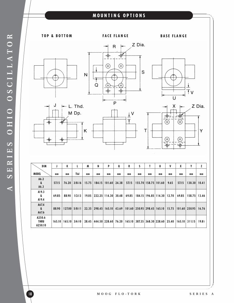
M O U N T I N G O P T I O N S
M O O G F L O - T O R K S E R I E S A
T O P & B O T T O M F A C E F L A N G E B A S E F L A N G E
DIM J K L M N P Q R S T U V X Y Z
MODEL mm mm Thd mm mm mm mm mm mm mm mm mm mm mm mm
A6.2& 57.15 76.20 3/8-16 15.75 184.15 101.60 24.38 57.15 155.70 158.75 101.60 9.65 57.15 130.30 10.41
A6.3
A19.3& 69.85 88.90 1/2-13 19.05 222.25 114.30 30.48 69.85 184.15 196.85 114.30 12.70 69.85 158.75 13.46
A19.4
A67.4& 88.90 127.00 5/8-11 22.35 298.45 165.10 43.69 101.60 250.95 298.45 165.10 15.75 101.60 250.95 16.76
A67.6
A250.6THRU 165.10 165.10 3/4-10 28.45 444.50 228.60 76.20 165.10 387.35 368.30 228.60 25.40 165.10 311.15 19.81
A250.10

A SERIES OHIO OSCILLATOR
F L O - T O R KS E R I E S A 19
S H A F T O P T I O N S
H O L L O W E DK E Y E D
M A L E S P L I N ES A E 1 0 B
F E M A L E S P L I N ES A E 1 0 B
S Q U A R E
DIM A B C D E F G H J K L M N P R S
MODELmm mm mm mm mm mm mm mm mm mm mm mm mm mm mm mm
A6.2 22.23 4.75 25.35 21.69 3.89 22.20 19.10 3.43 15.88& 120.65 25.40 39.72 30.99 23.11 31.75
A6.3 22.30 4.78 25.32 21.56 3.86 22.23 19.13 3.48 15.82
A19.3 25.40 6.35 31.70 27.15 4.88 31.72 27.28 4.90 25.40& 63.50 31.75 31.75 56.64 72.39 32.00 38.86
A19.4 25.50 6.38 31.65 27.02 4.85 31.75 27.33 4.95 25.27
A67.4 44.48 9.53 50.72 43.57 7.82 44.45 38.20 6.88 38.10& 91.95 51.56 50.80 75.18 68.33 45.21 69.85
A67.6 44.53 9.55 50.67 43.38 7.80 44.43 38.23 6.93 37.07
A250.6 76.23 19.08 76.07 65.23 11.76 76.15 65.48 11.81 63.50THRU 304.80 76.20 118.11 76.02 77.72 74.68
A250.10 76.28 19.10 76.12 65.35 11.79 76.20 65.53 11.89 63.37

A SERIES OHIO OSCILLATOR
20
P O S I T I O N I D E N T I F I C A T I O N & P O R T I N G
M O O G F L O - T O R K A S E R I E S
The following identification codes are used to specify
the location of cushions, cushion adjustments, side
ports, mountings, or other special requ irements.
SURFACE IDENTIFICATION
MS1 - Front surface or face - bearing cap side
MS2 - Bottom surface - opposite keyway when actuator is at mid-rotation (applies to standard keyway location only).
MS3 - Back surface - opposite of bearing cap side
MS4 - Top surface - opposite bottom surface.
CYLINDER END IDENTIFICATIONCylinder ends are numerically identified as shown
below. The left cylinder end is No. 1 and the right
cylinder end is No. 2 when looking at the front face
with the keyway at 12 o’clock and the rotary actuator
at mid-rotation.
PORTS - Air Rotary Actuators
Standard and optional port configuration for Ohio Oscillator pneumatic rotary actuators.
CONSULTFACTORY FOR OPTIONAL SIZES
BSPP BSPP
RECOMMENDED EXTERNA L STROKE ADJUSTERS SIDE PORTSTANDARD TUBE SIZE MAXIMUM MAXIMUM
MODEL BSPP PORT O.D. (mm)
A6.2
A6.3 G 1/4-19 9.50
A19.3 G 1/4-19 BSPP
A19.4
G 3/8-19 12.7
A67.4
A67.6 G 1/2-14 15.9
A250.6G 3/4-14 19.05
A250.8
A250.10 G 1-11 31.75
CONSULTFACTORY
A SERIES OHIO OSCILLATOR
M O O G F L O - T O R KA S E R I E S 21
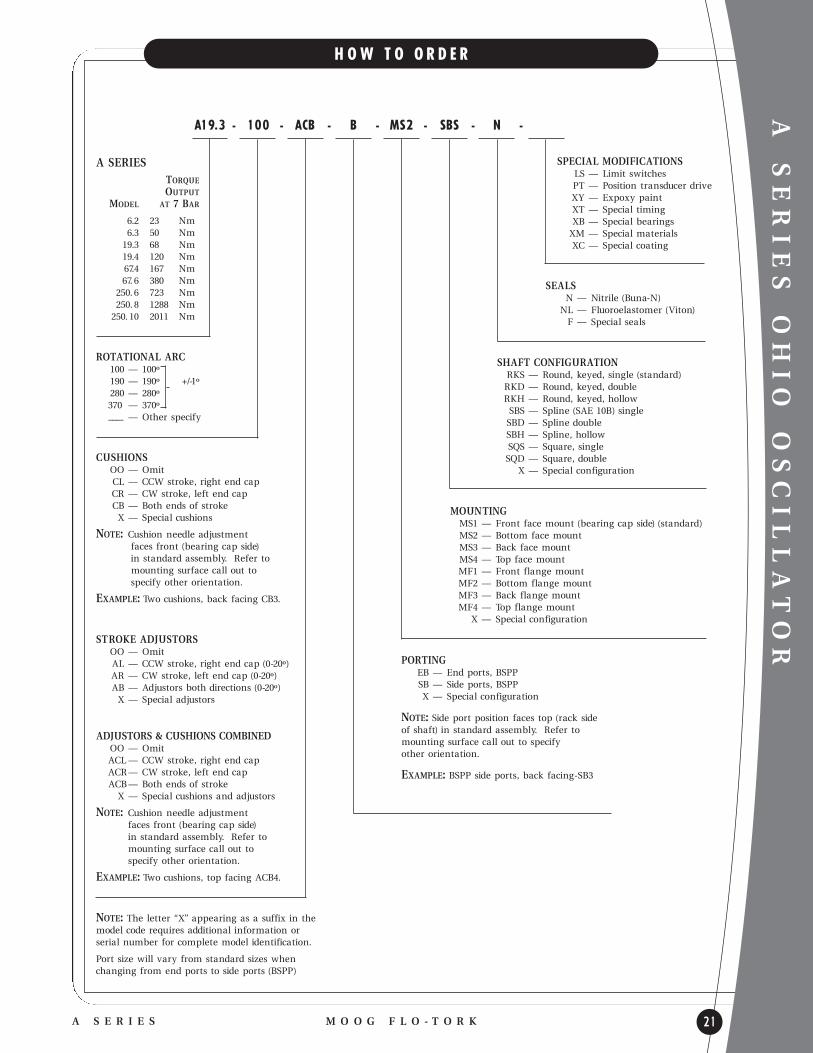
H O W T O O R D E R
A SERIESTORQUEOUTPUT
MODEL AT 7 BAR
6.2 23 Nm 6.3 50 Nm
19.3 68 Nm19.4 120 Nm67.4 167 Nm67. 6 380 Nm
250. 6 723 Nm250. 8 1288 Nm
250. 10 2011 Nm
ROTATIONAL ARC100 — 100º 190 — 190º +/-1º 280 — 280º370 — 370º
–––- — Other specify
CUSHIONSOO — Omit CL — CCW stroke, right end cap CR — CW stroke, left end cap CB — Both ends of stroke X — Special cushions
NOTE: Cushion needle adjustment faces front (bearing cap side) in standard assembly. Refer to mounting surface call out to specify other orientation.
EXAMPLE: Two cushions, back facing CB3.
STROKE ADJUSTORSOO — Omit AL — CCW stroke, right end cap (0-20º)AR — CW stroke, left end cap (0-20º) AB — Adjustors both directions (0-20º) X — Special adjustors
ADJUSTORS & CUSHIONS COMBINEDOO — Omit ACL — CCW stroke, right end capACR— CW stroke, left end cap ACB— Both ends of stroke
X — Special cushions and adjustors
NOTE: Cushion needle adjustment faces front (bearing cap side) in standard assembly. Refer to mounting surface call out to specify other orientation.
EXAMPLE: Two cushions, top facing ACB4.
NOTE: The letter “X” appearing as a suffix in themodel code requ ires additional information or serial number for complete model identification.
Port size will vary from standard sizes whenchanging from end ports to side ports (BSPP)
A19.3 - 100 - ACB - B - MS2 - SBS - N -
SPECIAL MODIFICATIONSLS — Limit switchesPT — Position transducer drive XY — Expoxy paint XT — Special timing XB — Special bearingsXM — Special materialsXC — Special coating
MOUNTINGMS1 — Front face mount (bearing cap side) (standard) MS2 — Bottom face mount MS3 — Back face mount MS4 — Top face mount MF1 — Front flange mountMF2 — Bottom flange mount MF3 — Back flange mount MF4 — Top flange mount
X — Special configuration
PORTINGEB — End ports, BSPP SB — Side ports, BSPP X — Special configuration
NOTE: Side port position faces top (rack side of shaft) in standard assembly. Refer tomounting surface call out to specify other orientation.
EXAMPLE: BSPP side ports, back facing-SB3
SHAFT CONFIGURATIONRKS — Round, keyed, single (standard) RKD — Round, keyed, double RKH — Round, keyed, hollow SBS — Spline (SAE 10B) singleSBD — Spline doubleSBH — Spline, hollowSQS — Square, singleSQD — Square, double
X — Special configuration
SEALSN — Nitrile (Buna-N)
NL — Fluoroelastomer (Viton)F — Special seals

P SERIES
22
P N E U M A T I C R O T A R Y A C T U A T O R S
M O O G F L O - T O R K P S E R I E S
A - 1 0 0 0 T I E R O D D E S I G N S H O W N
D E S I G N F E A T U R E S
l HIGH PRESSURE AIR - 8.62 BAR
l TORQUE RANGE - 34 TO 1130 NM @ 7 BAR
l STANDARD ROTATIONS - 94, 184 DEGREES
l BSPP
l RACK & PINION - HIGH MECHANICAL EFFICIENCY
l DUAL RACK DESIGN - DOUBLES TORQUE OUTPUT
l PISTON SEALS - O-RING
l ZERO LEAKAGE - HIGH VOLUMETRIC EFFICIENCY
l OPERATING TEMPERATURE - -18O TO 93O C
l (P300 THRU P2000) EXTRUDED ALUMINUMHOUSING - HARD COAT ANODIZED
l GEARING - SINGLE TOOTH FULL LOAD CAPACITY
S T A N D A R D O P T I O N S
l STROKE ADJUSTORS (ONE DIRECTION ONLY)
l MOUNTING VARIATIONS
l SHAFTING VARIATIONS
l CLOCKWISE OR COUNTERCLOCKWISE ROTATIONS
l CUSTOMER SPECIFIED ROTATIONS
l CUSTOM SEALING ARRANGEMENTS
l SPECIAL COATINGS
P3 0 0 T H R U P 2 0 0 0 S H O W N
Gearing l DUAL RACK DESIGN
l LARGE RACK BEARING SUPPORT AREA
l HARD COATED ALUMINUM RACK
l SINGLE TOOTH LOAD CAPACITY
End Caps l ANODIZED ALUMINUM
l OPTIONAL ADJUSTORS
Housings l HIGH STRENGTH ALUMINUM
l HARD COAT ANODIZED
l DUCTILE IRON - P4000 & LARGERGear Chamber l LIFE TIME LUBRICATEDl ELASTOMER SEALED
Pinion Shaft l WORK HARDENED STEEL
l RUGGED ONE-PIECE CONSTRUCTIONl SINGLE TOOTH LOAD CAPACITY
Bearings l PRE-LUBRICATED - BRONZEl HIGH LOAD CAPACITY
l LOW FRICTION

P SERIES
M O O G F L O - T O R KP S E R I E S 23
E N V E L O P E D I M E N S I O N S
M O D E L P3 0 0 , P1 0 0 0 & P 2 0 0 0
M O D E L P 4 0 0 0 , P 8 0 0 0 & P1 0 0 0 0
A B C D E F G H J K L M N P R S
MODEL ROTATIONNUMBER DEGREES mm mm mm mm mm mm mm mm mm mm mm mm mm mm mm mm
94º 167.89 M6 X 119.00
P300 63.50 63.50 44.45 44.45 X 4.76 X 25.40 4.76 14.29 15.24 16.00 N/A G 1/8 -2 8 N/A N/A19.05
184º 259.59 8DP
94º 213.36 M6 X 122.23
P1000 91.95 91.95 69.85 69.85 X 4.76 X 88.11 6.35 19.05 17.53 31.75 N/A G 1/4 - 19 N/A N/A22.28
184º 332.99 13DP
94º 276.10 M10 X 1.531.78
P2000 115.82 115.82 95.25 82.55 X 6.35 X 112.71 6.35 19.05 16.76 34.80 N/A G 1/4 - 19 N/A N/A 31.85
184º 449.07 19DP
94º 400.30 M12 X 1.7544.45
P4000 162.05 146.05 95.25 95.25 X 9.53 X 75.41 7.94 23.81 26.16 39.62 69.85 G 3/8 - 19 54.10 41.40† 44.53
184º 639.57 19DP
94º 435.88 M12 X 1.7544.45
P8000 184.15 177.80 95.25 95.25 X 9.53 X 91.28 9.53 28.58 29.97 56.13 79.38 G 3/8 - 19 54.86 54.10† 44.50
184º 695.20 19DP
94º 469.65 M16 X 250.83
P10000 193.55 188.91 127.00 127.00 X 12.70 X 95.25 9.53 28.58 32.51 56.13 82.55 G 3/8 - 19 63.50 57.15† 50.90
184º 749.05 25DP
* K e y w ay e n g a g e m e n t i s m e a s u r e d f r o m t h e f r o n t f a c e .† D i m e n s i o n s a r e s h o w n a s c a s t .

P SERIES
24
T Y P I C A L P E R F O R M A N C E
M O O G F L O - T O R K P S E R I E S
TORQUENM
282
226
169
113
56
0
TORQUENM
1,582
1,356
1,130
904
678
452
226
0
P300 4.92 14 20 34 42
P1000 16.39 45 68 113 141
P2000 32.77 90 136 226 282
P4000 65.55 181 271 452 565
P8000 131.10 362 542 904 1130
P10000 163.87 452 678 1130 1412
BAR 0 1.7 3.4 5.2 6.9 8.6
P2000
P300
P1000
P 4 0 0 0 T O P1 0 0 0 0
T O R Q U E O U T P U TV S .
P R E S S U R E
P10000
P4000
P8000
BAR 0 1.7 3.4 5.2 6.9 8.6
MODEL TORQUE NUMBER FACTOR
O U T P U T T O R Q U E ( N m ) A T VA R I O U S P R E S S U R E S * ( B A R )
2 . 7 6 4 . 1 4 6 . 8 9 8 . 6 2
P300 0.001 0.094 0.184
P1000 0.003 0.282 0.552
P2000 0.006 0.564 1.104
P4000 0.015 1.41 2.76
P8000 0.027 2.538 4.968
P10000 0.032 3.008 5.888
MODEL DISPLACEMENT NUMBER FACTOR
D I S P L A C E M E N T ( L ) P E R S T R O K E *
9 4 0 1 8 4 0
* D i s p l a c e m e n t ( L) = D i s p l a c e m e n t Fa c t o r xR o t a t i o n a l A r c ( d e g r e e s) .
E x a m p l e : P1 0 0 0 @ 1 8 4 º s w e e p s ( . 0 0 3 x 1 8 4 ) = . 5 5 2 L .
* O u t p u t To r q u e ( N m) = To r q u e f a c t o r x O p e r a t i n g P r e s s u r e ( b a r) .
E x a m p l e : M o d e l P 2 0 0 0 @ 4 . 1 4 b a r d e l i v e r s ( 3 2 .7 7 x 4 . 1 4 ) = 1 3 6 N m t o r q u e .
P R E S S U R EP R E S S U R E
P3 0 0 T O P 2 0 0 0
T O R Q U E O U T P U TV S .
P R E S S U R E

P SERIES
M O O G F L O - T O R KP S E R I E S 25
H O W T O O R D E R
P SERIESTORQUEOUTPUT
MODEL AT 7 BAR
P300 34 Nm P1000 173 NmP2000 226 NmP4000 452 NmP8000 904 NmP10000 1130 Nm
ROTATIONAL ARC94 — 94º
184 — 184º -0/+2º
–––- — Other specifyMaximum rotation of dualrack rotary actuators is 184º
CUSHIONSNot Available
STROKE ADJUSTORSOO — Omit AL — Left end cap (0-6º)AR — Right end cap (0-6º)AB — Both end caps (0-6º)X — Special adjustors*
Stroke adjustment affects only the outward piston stroke.
PORTINGEB — BSPP (standard)
X —Special porting*
P4000 - 94 - A L - EB - MS13 - RKH - N - CW -
MOUNTINGMS1 — Front face (bearing cap side) - standard MS2 — Bottom surface MS3 — Back surface MS4 — Top surface
X — Special configuration* Multiple mounting surfaces are designated by combining numerals(i.e., front and back is MS13).
MS2 and MS4 mountings are not available on P4000 To P10000.
*NOTE: The letter ‘X’ appearing as a suffix in the model code requ ires additional information or serial number for complete model identification.
SHAFT CONFIGURATIONRKS — Single end, keyed (standard on P300) RKD — Double end, keyed both ends of shaftRKH — Hollow, keyed (standard on
P1000 to P10000) X — Special shaft*
SEALSN — Nitrile (Buna-N) - standard F — Fluoroelastomer (Viton)X — Special seal*
ROTATION DIRECTIONCW — Clockwise rotation
(standard) CCW — Counter-clockwise
rotation
NOTE: Clockwise rotation is with keyway rotating from 12 o’clock position to 3 o’clock position when facing the snap ring side with the pressure ports on top. For counter-clockwise rotation the keyway rotates from 12 o’clock position to the 9 o’clock position.
SPECIAL MODIFICATIONS
XT — Special timing of keyway
XM — Special materials XC — Special coatings SR — Spring return X — Special features*

HYDRAULIC SERIES
26
H Y D R A U L I C R O T A R Y A C T U A T O R S
M O O G F L O - T O R K H Y D R A U L I C S E R I E S
D E S I G N F E A T U R E S
l HEAVY DUTY HYDRAULIC - 206.8 BAR MAX.
l TORQUE RANGE - 102 TO 67791 NM@ 207 BAR
l STANDARD ROTATIONS - 90, 180, 360 DEGREES
l BSPP PORTS
l RACK & PINION - HIGH MECHANICAL EFFICIENCY
l ZERO LEAKAGE - HIGH VOLUMETRIC EFFICIENCY
l ANTI-FRICTION BEARINGS - HIGH EXTERNALLOAD CAPABILITY
l GEARING - SINGLE TOOTH FULL LOAD CAPACITY
l THROUGH SHAFT - POSITION READOUT SOURCE
l MINIMUM BREAKAWAY PRESSURE - 3.4 BAR
l OPERATING TEMPERATURE - -180 TO 930 C
S T A N D A R D O P T I O N S
l DECELERATING CUSHIONS
l STROKE ADJUSTORS
l CUSHIONS & STROKE ADJUSTORS
l END PORTS OR SIDE PORTS
l MOUNTING VARIATIONS
l SHAFTING VARIATIONS
l CUSTOMER SPECIFIED ROTATIONS
l CUSTOM SEALING ARRANGEMENTS
l AIR BLEEDS
l SPECIAL COATINGS
Bearings l BALL OR TAPERED ROLLER
l SUBSTANTIAL EXTERNALLOAD CAPACITY
Tie Rods l PRE-STRESSED STEEL ALLOY
Keyway Timing l 12 O’CLOCK POSITION
AT MID-STROKE OF ROTATION
Pinion Shaft l HIGH STRENGTH STEEL ALLOY
l RUGGED ONE PIECE CONSTRUCTION
l SINGLE TOOTH LOAD CAPACITY
Piston Seals l ZERO LEAKAGE
RADIAL SEALS
l O-RING & DOUBLEBACK-UP RINGS
l ENERGIZED LIP SEAL(3700 - 7500)
Gear Chamber l OIL-FILLED,
ELASTOMER SEALED
l NON-PRESSURIZEDWITH RELIEF VALVE
Housingl HIGH STRENGTH
DUCTILE IRON
l OPTIONAL MOUNTINGSURFACES
Gearingl HIGH STRENGTH
HARDENED STEEL
l SINGLE TOOTHLOAD CAPACITYPistons and Racks
l PATENTED FLOATING PISTONDESIGN (75000 AND UP)
l ONE PIECE PISTON/RACKDESIGN (900 TO 30000)
l HIGH STRENGTH DUCTILE IRON
Cylinders l HEAVY WALL STEEL TUBING
l PRECISION HONED BORES
End Caps l STEEL BAR OR DUCTILE IRONOPTIONAL CUSHIONS AND ADJUSTORS

HYDRAULIC SERIES
M O O G F L O - T O R KH Y D R A U L I C S E R I E S 27
E N V E L O P E D I M E N S I O N S
H O L L O W S H A F T O P T I O N
A B C D E F G H J K L M N
MODEL NUMBER ROTATIONNUMBER RACKS DEGREES mm mm mm mm mm mm BSPP mm mm mm mm mm mm
900 1 90º 160.27 22.19 6.35 M8 X 1.25 15.88 4.75180º 208.03 75.69 76.20 33.27 X G 1/4 - 19 66.80 60.45 X 85.85
1800 2 360º 303.78 22.23 25.40 13DP 15.93 4.78
3700 1 90º 215.65 31.70 7.94 M10 X 1.5 22.23 4.75180º 285.50 100.08 114.30 47.75 X G 1/4 - 19 76.20 92.20 X 97.03
7500 2 360º 424.94 31.75 38.10 16 DP 22.28 4.78
15000 1 90º 324.87 57.10 14.29 M20 X 2.5 38.10 9.53180º 436.63 133.35 174.75 85.85 X G 1/2 -14 120.65 123.95 X 171.45
30000 2 360º 660.15 57.15 60.33 21DP 38.18 9.55
75000 1 90º 624.84 76.15 19.05 M24 X 3 69.85 15.88180º 848.11 219.20 292.10 114.30 X G 3/4 - 14 187.45 231.90 X 244.60
150000 2 360º 1295.15 76.20 85.75 41.00 69.90 15.90
300000 1 90º 887.20 126.95 31.75 M30 X 3.5 95.25 19.05180º 1166.60 368.30 419.10 190.50 X G 1 - 11 330.20 342.90 X 403.35
600000 2 360º 1725.40 127.00 152.40 44DP 95.35 19.08
“A” D i m e n s i o n s i n c r e a s e 2 1 . 3 4 m m p e r c u s h i o n e n d f o r M o d e l s 9 0 0 a n d 1 8 0 0 . “ C ” D i m e n s i o n s a r e “A s C a s t ”.

TORQUENm
16,947
15,252
13,558
11,863
10,168
8,474
6,779
5,084
3,389
1,695
0
67,788
61,009
54,230
47,452
40,673
33,894
27,11
20,336
13,558
6,779
0
T O R Q U E O U T P U TV S .
P R E S S U R E
HYDRAULIC SERIES
28
T Y P I C A L P E R F O R M A N C E
M O O G F L O - T O R K H Y D R A U L I C S E R I E S
TORQUENm
226
203
181
158
136
113
90
68
45
23
0
847
763
678
593
508
424
339
254
169
85
0
1800
900
BAR 0 34 69 103 138 172 207
7500
3700
P R E S S U R E
150000
75000
BAR 0 34 69 103 138 172 207
600000
300000
P R E S S U R E
TORQUENm
3,389
3,050
2,712
2,373
2,034
1,695
1,356
1,017
678
339
0BAR 0 34 69 103 138 172 207
30000
15000
P R E S S U R E
M O D E L T O R Q U EO U T P U T T O R Q U E ( N m ) @ VA R I O U S P R E S S U R E * ( B A R )
N O . F A C T O R * 3 4 . 4 7 5 1 . 7 1 1 0 3 . 4 2 1 7 2 . 3 7 2 0 6 . 8 4
900 0.49 34 50 68 84 101
1800 0.98 68 101 135 169 203
3700 2.02 139 208 279 347 418
7500 4.10 283 422 566 705 849
15000 8.19 565 844 1130 1409 1695
30000 16.4 1131 1688 2262 2819 3393
75000 41.0 2827 4220 5654 7047 8481
150000 81.9 5654 8440 11308 14094 16962
300000 164 11307 16879 22614 28186 33921
600000 328 22614 33757 45228 56371 67842
M O D E L D I S P L A C E M E N TD I S P L A C E M E N T ( L ) S T R O K E *
N U M B E R F A C T O R * 9 0 0 1 8 0 0 3 6 0 0
900 0.0001 0.009 0.018 0.036
1800 0.0002 0.018 0.036 0.072
3700 0.0004 0.036 0.072 0.144
7500 0.0008 0.144 0.144 0.288
15000 0.0016 0.288 0.288 0.576
30000 0.0032 0.009 0.576 1.152
75000 0.0078 0.702 1.404 2.808
150000 0.016 1.44 2.88 5.76
300000 0.031 2.79 5.58 11.16
600000 0.062 5.58 11.16 22.32
* O u t p u t To r q u e ( N m) = To r q u e Fa c t o r x O p e r a t i n g P r e s s u r e ( b a r) . E x a m p l e : M o d e l 3 0 0 0 0 @ 1 0 3 b a r d e l i v e r s ( 1 6 .4 x 1 0 3 ) = 1 6 8 8 N m t o r q u e .
* D i s p l a c e m e n t ( L) = D i s p l a c e m e n t Fa c t o r x R o t a t i o n a l A r c ( d e g r e e s) . E x a m p l e : 1 5 0 0 0 x 1 8 0 º d i s p l a c e s ( . 0 0 1 6 x 1 8 0 ) = . 2 8 8 L .

HYDRAULIC SERIES
M O O G F L O - T O R KH Y D R A U L I C S E R I E S 29
E N D C A P O P T I O N S
INTERNAL STROKE ADJUSTOR & ADJUSTABLE CUSHIONThe 0-5º internal stroke adjustor and the adjustable
cushion are combined into a single option. This design
permits the full cushioning effect at any stroke
adjustment setting.
CAUTION: Cushion needles should be set between one half
and one full turn from seated position. Setting
should result in continuous speed reduction
throughout the cushion length. Needle adjustment
is set too far closed when there is an abrupt
change in speed as the actuator enters the
cushion. Never operate with needle in seated
position or unscrewed beyond the point where
the seal relief in the thread is visible.
CAUTION: Cushion needle adjustment is a crucial factor in
achieving optimum cushion performance. If
the needle valve setting is too far open, cushion
capacity will be reduced, or rendered ineffective;
if set too far closed, cushion action will generate
shock and pressure spikes in excess of
actuator rating.
*NOTE: When ordering a double rack model with stroke
adjustors it is necessary to order end of stroke
adjustors for both cylinders. When only one stroke
adjustor is used for end of stroke adjustment on a
double rack model the maximum operating pressure
must be limited to 103.4 bar.
*NOTE: Cushions and external stroke adjustors are not
available on the same cylinder end cap for
standard models. Consult factory for special
design considerations.
EXTERNAL STROKE ADJUSTORSExternal stroke adjustors permit 0-30º of adjustment at
the end of rotation. The adjustor stop, which contains
the port, is set in position with a wrench on external
flats and locked in place with a jam nut against a
thread seal.
CUSHIONSCushions are designed to provide smooth deceleration,
external energy absorption and noise reduction, over
the last 15º of rotation. Cushions trap flu id at the end
of stroke by locking or restricting the discharge port.
The trapped flu id is diverted through a small needle
valve which generates a back pressure on the discharge
side of the piston. This back pressure resists the forces
exerted on the internal parts of the rotary actuator,
thus causing a slowing of the external mass.
INTERNAL STROKE ADJUSTORSInternal stroke adjustors permit 0-5º of adjustment. A
threaded bushing within the end cap is set in position
by a hex wrench inserted through the port and locked
in place with a set screw.
M O D E L S 9 0 0 T O 7 5 0 0 M O D E L S 1 5 0 0 0 A N D U P
A D J U S T A B L E C U S H I O N

HYDRAULIC SERIES
30
M O U N T I N G O P T I O N S
M O O G F L O - T O R K H Y D R A U L I C S E R I E S
T O P A N D F A C E F L A N G E B A S E F L A N G EB O T T O M
N O T E : D i m e n s i o n s a r e s y m m e t r i c a l a b o u t t h e c e n t e r l i n e o f t h e p i n i o n .
NOTE: Consult factory for dowelling recommendations
DIM A B C D E F G H J K L M N P R S
MODEL mm mm mm mm mm mm mm mm mm mm mm mm mm mm mm mm
900 M8X 1.2575.69 37.59 66.80 60.45 X 120.65 88.90 63.50 101.60 11.18 9.65 47.75 120.65 88.90 63.50 101.60
1800 13mm DP
3700 M10 X 1.5 114.30 57.15 76.20 76.20 X 184.15 111.25 76.20 146.05 14.22 12.70 69.85 165.10 111.25 76.20 127.00
7500 16mm DP
1500 M20 X 2.5 171.70 85.85 120.65 95.25 X 241.30 171.45 120.65 209.55 17.53 16.00 101.60 196.85 171.45 133.35 171.45
30000 21mm DP
75000 M24 X 3 287.27 143.76 187.45 158.75 X 374.65 285.75 234.95 339.85 20.57 25.40 169.16 298.45 285.75 234.95 266.70
150000 44mm DP
300000 M30 X 3.5413.00 206.50 254.00 292.10 X 590.55 457.20 381.00 539.75 26.92 31.75 238.25 495.30 457.20 304.80 419.10
600000 44mm DP

HYDRAULIC SERIES
M O O G F L O - T O R KH Y D R A U L I C S E R I E S 31
S H A F T O P T I O N S
H O L L O W M A L E S P L I N E F E M A L E S P L I N EK E Y E D S A E 1 0 B S A E 1 0 B S Q U A R E
A B C D E F G H J K L M N P R S
MODELNUMBER mm mm mm mm mm mm mm mm mm mm mm mm mm mm mm mm
900 15.88 4.75 22.15 18.85 3.35 19.02 17.32 2.92 15.8273.66 22.10 33.27 31.75 19.05 31.75
1800 15.93 4.78 22.17 18.97 3.40 19.05 17.35 2.97 15.88
3700 22.23 4.75 31.65 4.83 22.20 19.10 3.43 25.2797.79 27.15 31.75 47.75 38.10 22.38 47.75
7500 22.28 4.78 31.70 4.88 22.23 19.13 3.48 25.40
15000 38.10 9.53 57.02 8.76 44.45 38.20 6.88 44.32131.83 48.97 57.15 85.85 44.45 45.97 85.85
30000 38.18 9.55 57.07 8.81 44.58 38.33 6.93 44.45
75000 69.85 15.88 76.07 11.73 76.20 65.61 11.81 63.37217.42 65.35 76.20 114.30 76.20 76.96 95.25
150000 69.90 15.90 76.12 11.79 76.30 65.74 11.89 63.47
300000 95.25 19.05 126.80 19.66 101.52 87.12 15.77 101.47366.78 108.97 127.00 190.50 101.60 103.12 187.45
600000 95.35 19.08 126.85 19.71 101.60 87.30 15.85 101.60
NO INTERNAL
RELIEF DIAMETER
HYDRAULIC SERIES
32
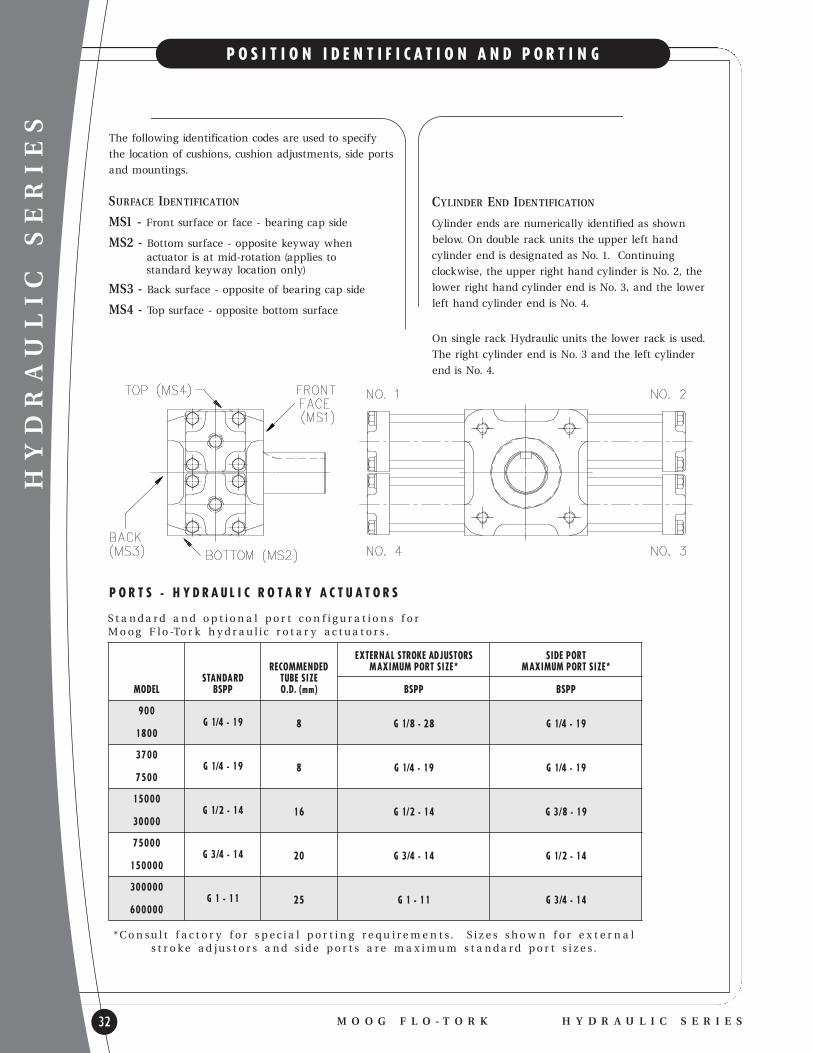
P O S I T I O N I D E N T I F I C A T I O N A N D P O R T I N G
M O O G F L O - T O R K H Y D R A U L I C S E R I E S
The following identification codes are used to specify
the location of cushions, cushion adjustments, side ports
and mountings.
SURFACE IDENTIFICATION
MS1 - Front surface or face - bearing cap side
MS2 - Bottom surface - opposite keyway when actuator is at mid-rotation (applies to standard keyway location only)
MS3 - Back surface - opposite of bearing cap side
MS4 - Top surface - opposite bottom surface
S t a n d a r d a n d o p t i o n a l p o r t c o n f i g u r a t i o n s f o r M o o g F l o -To r k h y d r a u l i c r o t a r y a c t u a t o r s .
P O R T S - H Y D R A U L I C R O T A R Y A C T U A T O R S
EXTERNA L STROKE ADJUSTORS SIDE PORTRECOMMENDED MAXIMUM PORT SIZE* MAXIMUM PORT SIZE*
STANDARD TUBE SIZEMODEL BSPP O.D. (mm) BSPP BSPP
900 8 G 1/8 - 28 G 1/4 - 19G 1/4 - 19
1800
3700 8 G 1/4 - 19 G 1/4 - 19G 1/4 - 19
7500
15000 16 G 1/2 - 14 G 3/8 - 19G 1/2 - 14
30000
7500020 G 3/4 - 14 G 1/2 - 14 G 3/4 - 14
150000
300000 25 G 1 - 11 G 3/4 - 14G 1 - 11
600000
* C o n s u l t f a c t o r y f o r s p e c i a l p o r t i n g r e q u i r e m e n t s . S i z e s s h o w n f o r e x t e r n a ls t r o ke a d j u s t o r s a n d s i d e p o r t s a r e m a x i m u m s t a n d a r d p o r t s i z e s .
CYLINDER END IDENTIFICATION
Cylinder ends are numerically identified as shown
below. On double rack units the upper left hand
cylinder end is designated as No. 1. Continu ing
clockwise, the upper right hand cylinder is No. 2, the
lower right hand cylinder end is No. 3, and the lower
left hand cylinder end is No. 4.
On single rack Hydraulic units the lower rack is used.
The right cylinder end is No. 3 and the left cylinder
end is No. 4.
HYDRAULIC SERIES
TORQUEOUTPUT NUMBER
MODEL AT 207 BAR OF RACKS
900 102 Nm 1 1,800 203 Nm 2 3,700 418 Nm 1 7,500 847 Nm 2
15,000 1695 Nm 1 30,000 339 Nm 2 75,000 8474 Nm 1 150,000 16948 Nm 2 300,000 33895 Nm 1 600,000 67791 Nm 2
ROTATIONAL ARC90 — 90º
180 — 180º -0/+2º360 — 360º
–––- — Other specify
CUSHIONS**OO — OmitCL — Counter-clockwise stroke CR — Clockwise stroke CB — Both ends of stroke CQ — Four cushions (two rack units only) X — Special cushions*
NOTE: Cushion needle adjustment faces front (bearing retainer side) in standard assembly. Refer to mounting surface call out to specify other orientation. Example 1: two cushions, back facing — CB3; Example 2: four cushions, top and bottom facing — CQ24.
STROKE ADJUSTOR**OO — Omit AIL — Counter-clockwise stroke
(0-5º internal) AIR — Clockwise stroke (0-5º internal) AIB — Both ends of stroke (0-5º internal) AIQ — Four internal adjustors
(two rack units only) AEL — Counter-clockwise stroke
(0-30º external) AER— Clockwise stroke (0-30º external) AEB — Both ends of stroke (0-30º external) AEQ— Four external adjustors
(two rack units only) X — Special adjustors
CUSHIONS & INTERNAL ADJUSTORS**OO — Omit
AICL — Counter-clockwise stroke (0-5º internal)
AICR — Clockwise stroke (0-5º internal) AICB — Both ends of stroke
(0-5º internal) AICQ — Four internal adjustors & cushions
(two rack units only) X — Special cushions & adjustors*
CUSHIONS & EXTERNAL ADJUSTORSNot available on same end
HYDRAULIC SERIES
M O O G F L O - T O R KH Y D R A U L I C S E R I E S 33
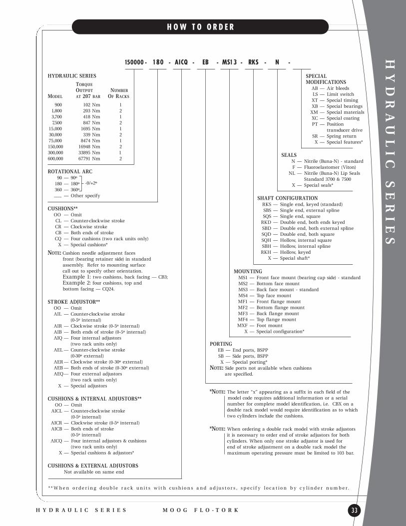
H O W T O O R D E R
150000 - 180 - AICQ - EB - MS13 - RKS - N -
SPECIAL MODIFICATIONS
AB — Air bleeds LS — Limit switchXT — Special timing XB — Special bearings XM — Special materials XC — Special coating PT — Position
transducer drive SR — Spring return X — Special features*
MOUNTINGMS1 — Front face mount (bearing cap side) - standard MS2 — Bottom face mount MS3 — Back face mount - standard MS4 — Top face mount MF1 — Front flange mount MF2 — Bottom flange mount MF3 — Back flange mount MF4 — Top flange mount MXF — Foot mount
X — Special configuration*
SHAFT CONFIGURATIONRKS — Single end, keyed (standard) SBS — Single end, external spline SQS — Single end, square
RKD — Double end, both ends keyed SBD — Double end, both external spline SQD — Double end, both square SQH — Hollow, internal square SBH — Hollow, internal spline RKH — Hollow, keyed
X — Special shaft*
SEALSN — Nitrile (Buna-N) - standard F — Fluoroelastomer (Viton)
NL — Nitrile (Buna-N) Lip Seals Standard 3700 & 7500
X — Special seals*
PORTINGEB — End ports, BSPP SB — Side ports, BSPP X — Special porting*
NOTE: Side ports not available when cushions are specified.
* * W h e n o r d e r i n g d o u b l e r a c k u n i t s w i t h c u s h i o n s a n d a d j u s t o r s , s p e c i f y l o c a t i o n b y c y l i n d e r n u m b e r .
*NOTE: The letter “x” appearing as a suffix in each field of the model code requ ires additional information or a serial number for complete model identification, i.e. CBX on a double rack model would requ ire identification as to which two cylinders include the cushions.
*NOTE: When ordering a double rack model with stroke adjustors it is necessary to order end of stroke adjustors for both cylinders. When only one stroke adjustor is used for end of stroke adjustment on a double rack model the maximum operating pressure must be limited to 103 bar.

HYDRAULIC SERIES OHIO OSCILLATOR
34
H Y D R A U L I C R O T A R Y A C T U A T O R S
M O O G F L O - T O R K H Y D R A U L I C S E R I E S
D E S I G N F E A T U R E S
l HEAVY DUTY HYDRAULIC - 138 BAR MAX
l TORQUE RANGE - 136 TO 54,007 NM@ 138 BAR
l STANDARD ROTATIONS - 100, 190, 280, 370 DEGREES
l RACK & PINION - HIGH MECHANICAL EFFICIENCY
l ZERO LEAKAGE - HIGH VOLUMETRIC EFFICIENCY
l TAPERED ROLLER BEARINGS - HIGH EXTERNALLOAD CAPACITY
l PISTON SEALS - PRE-LOADED LIPS SEALS
l GEARING - SINGLE TOOTH FULL LOAD CAPACITY
l THROUGH SHAFT - POSITIONINSTRUMENTATION DRIVE
l OPERATING TEMPERATURE - -180 TO 930 C
S T A N D A R D O P T I O N S
l ADJUSTABLE CUSHIONS
l STROKE ADJUSTORS
l COMBINED CUSHIONS & STROKE ADJUSTORS
l BSPP
l ALTERNATIVE MOUNTING ARRANGEMENTS
l ALTERNATIVE SHAFT CONFIGURATIONS
l CUSTOM ROTATIONAL ARCS
l SIDE PORTED END CAPS
l SPECIAL SEALS
l AIR BLEEDS (FOR HYDRAULIC SERVICE)
Bearings l BALL OR TAPERED ROLLER
l SUBSTANTIAL EXTERNALLOAD CAPACITY
Tie Rods l PRE-STRESSED STEEL ALLOY Keyway Timing
l 12 O’CLOCK POSITIONAT MID-STROKE OF ROTATION
Pinion Shaft l HIGH STRENGTH STEEL ALLOY
l RUGGED ONE PIECE CONSTRUCTION
l SINGLE TOOTH LOAD CAPACITY
Piston Seals l ZERO LEAKAGE RADIAL SEALS
l O-RING & DOUBLE BACK-UP RINGS
l ENERGIZED LIP SEAL
Gear Chamber l OIL-FILLED,
ELASTOMER SEALED
l NON-PRESSURIZEDWITH RELIEF VALVE
Housingl HIGH STRENGTH DUCTILE IRON
l OPTIONAL MOUNTING SURFACES
Gearingl HIGH STRENGTH
HARDENED STEEL
l SINGLE TOOTHLOAD CAPACITY
Pistons and Racks l PATENTED FLOATING PISTON
DESIGN (H251 AND UP) l ONE PIECE PISTON/RACK
DESIGN (H6 TO H133) l HIGH STRENGTH DUCTILE IRON
Cylinders l HEAVY WALL STEEL TUBING
l PRECISION HONED BORES
End Caps l STEEL BAR OR DUCTILE IRONOPTIONAL CUSHIONSAND ADJUSTORS

HYDRAULIC SERIES OHIO OSCILLATOR
E N V E L O P E D I M E N S I O N S
TABULATED DIMENSIONS ARE FOR BASE MODEL, STANDARD CONFIGURATION. THE SELECTION OF OPTIONS MAY ALTER ENVELOPE DIMENSIONS. REFER TO OPTIONS SECTION OR CONSULT FACTORY FOR ADDITIONAL INFORMATION.
A B C* D E F G H J K L M N P R T
MODEL NO. ROTATION (W x L) (W x H)NUMBER RACKS DEGREES mm mm mm mm mm mm mm mm mm mm mm mm mm mm mm mm
100 205.99190 265.94
H6 1 280 325.88 M8370 385.57 76.07 B + E 25.30 6.35 4.76 22.23 X
71.37 107.95 107.95 9.53 ONE N/A X 32.51 X 1/4-19 91.95 1100 205.99 76.20 PILOT 25.35 25.4 3.18 22.30 BSPP X190 265.94 ONLY 16mm
H12 2 280 325.88 DP370 385.57
100 260.10190 339.85
H19 1 280 419.61 M12370 499.36 88.77 88.77 31.70 7.94 6.35 25.40 1/4-19 X
87.38 139.70 136.65 11.68 110.74 X 41.40 X BSPP 111.25 1.5100 260.10 88.90 88.90 31.75 31.75 4.76 25.50 X190 339.85 13MM
H37 2 280 419.61 DP370 499.36
100 329.95190 441.71 M16
H67 1 280 553.47 X370 665.99 126.87 126.87 50.75 12.7 9.53 44.48 2
125.48 203.20 196.85 15.75 156.97 X 75.44 X 1/2-14 155.45 X100 329.95 127.00 127.00 50.80 50.8 6.35 44.53 BSPP 23MM190 441.71 DP
H133 2 280 553.47370 665.99
100 621.03190 833.88
H251 1 280 1046.73 M20370 1257.05 215.77 215.77 76.15 19.05 19.05 76.23 3/4-14 X
177.80 307.98 311.15 24.89 227.58 X 76.71 X X 254.00 2.5100 621.03 † 215.90 215.90 76.20 60.33 12.7 76.28 BSPP X190 833.88 29MM
H501 2 280 1046.73 DP370 1257.05
100 1006.09190 1379.47
H1002 1 280 1914.65 M24370 2093.98 355.47 355.47 126.95 25.4 25.4 114.33 X
279.40 488.95 482.60 30.99 341.63 X 174.75 X 1-11 431.80 1.5100 1006.09 355.60 355.60 127.00 123.8 19.05 114.48 BSPP X190 1379.47 38MM
H2002 2 280 1914.65 DP370 2093.98
† MO D E L H 2 5 1 / H 5 0 1 C = 3 0 7. 9 8 C / 2 = 1 5 8 .7 5 * D I M E N S I O N C I S A S C A S T F O R M O D E L S H 1 9 T H RU H 2 0 0 2
35H Y D R A U L I C S E R I E S

HYDRAULIC SERIES OHIO OSCILLATOR
36
T Y P I C A L P E R F O R M A N C E
E N D C A P O P T I O N S
M O O G F L O - T O R K H Y D R A U L I C S E R I E S
* O u t p u t To r q u e ( N m) = To r q u e Fa c t o r x O p e r a t i n g P r e s s u r e ( b a r) . E x a m p l e : M o d e l H 6 7 @ 6 9 b a r d e l i v e r s ( 9 . 8 3 x 6 9 ) = 6 7 8 N m t o r q u e .
* D i s p l a c e m e n t ( L) = D i s p l a c e m e n t Fa c t o r x R o t a t i o n a l A r c ( d e g r e e s) . E x a m p l e : M o d e l H 6 7 @ 1 0 0 0 s w e e p s ( . 0 0 2 x 1 0 0 ) = . 2 L .
M O D E L D I S P L A C E M E N TD I S P L A C E M E N T ( L ) P E R S T R O K E
N U M B E R F A C T O R * 1 0 0 O 1 9 0 O 2 8 0 O 3 7 0 O
H6 0.0002 0.02 0.038 0.056 0.074
H12 0.0004 0.04 0.076 0.112 0.148
H19 0.0006 0.06 0.114 0.168 0.222
H37 0.001 0.1 0.19 0.28 0.37
H67 0.002 0.2 0.38 0.56 0.74
H133 0.004 0.4 0.76 1.12 1.48
H251 0.008 0.8 1.52 2.24 2.96
H501 0.016 1.6 3.04 4.48 5.92
H1002 0.04 4 7.6 11.2 14.8
H2002 0.08 8 15.2 22.4 29.6
M O D E L T O R Q U EO U T P U T T O R Q U E ( N m ) @ VA R I O U S P R E S S U R E I N B A R *
N U M B E R F A C T O R * 3 4 5 1 6 9 1 0 3 1 3 8
H6 0.982 33.4 50.1 67.8 101 136
H12 2.05 69.7 105 141 211 283
H19 2.95 100 150 204 304 407
H37 6.39 217 326 441 658 882
H67 9.83 334 501 678 1010 1360
H133 20.9 711 1070 1440 2150 2880
H251 39.3 1340 2000 2710 4050 5420
H501 84.3 2870 4300 5820 8680 11600
H1002 181 6150 9230 12500 18600 25000
H2002 391 13300 19900 27000 40300 54000
TORQUE
DISPLACEMENT
N O T E : E x c e e d i n g m a x i m u m p r e s s u r e m ay b e d e t r i m e n t a l t o t h e a c t u a t o r a n d m ay r e d u c e t h e c y c l e l i f e . C o n s u l t f a c t o r y f o r a p p l i c a t i o n s w h e r e m a x i m u m p r e s s u r e
m ay b e e x c e e d e d .
0 - 5 º I N T E R N A L S T R O K E A D J U S T O R
STROKE ADJUSTORSStroke adjustors are screw-type adjustable stops at
end of rotation. They should be used when the
exact final position of rotation is best determined
on the assembled machinery or when final position
requirements may vary with different machine
set ups.
INTERNAL STROKE ADJUSTORSInternal stroke adjustors permit 0-5º of adjustment.
A threaded bushing within the end cap is set in position
by a hex wrench inserted through the port and locked
in place with a set screw.
HYDRAULIC SERIES OHIO OSCILLATOR
M O O G F L O - T O R KH Y D R A U L I C S E R I E S 37
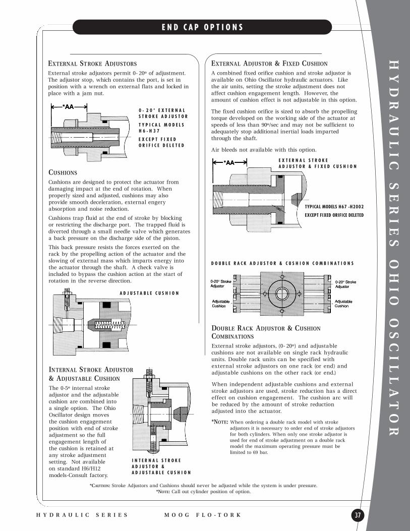
E N D C A P O P T I O N S
0 - 2 0 º E X T E R N A LS T R O K E A D J U S T O R
T Y P I C A L M O D E L S H 6 - H 3 7
E X C E P T F I X E D O R I F I C E D E L E T E D
A D J U S T A B L E C U S H I O N
INTERNAL STROKE ADJUSTOR& ADJUSTABLE CUSHIONThe 0-5º internal stroke adjustor and the adjustable cushion are combined into a single option. The Ohio Oscillator design moves the cushion engagement position with end of stroke adjustment so the full engagement length of the cushion is retained at any stroke adjustment setting. Not available on standard H6/H12 models-Consult factory.
EXTERNAL ADJUSTOR & FIXED CUSHIONA combined fixed orifice cushion and stroke adjustor isavailable on Ohio Oscillator hydraulic actuators. Like the air units, setting the stroke adjustment does notaffect cushion engagement length. However, the amount of cushion effect is not adjustable in this option.
The fixed cushion orifice is sized to absorb the propellingtorque developed on the working side of the actuator atspeeds of less than 90º/sec and may not be sufficient toadequately stop additional inertial loads imparted through the shaft.
A ir bleeds not available with this option.
EXTERNAL STROKE ADJUSTORSExternal stroke adjustors permit 0- 20º of adjustment.The adjustor stop, which contains the port, is set inposition with a wrench on external flats and locked inplace with a jam nut.
CUSHIONSCushions are designed to protect the actuator from damaging impact at the end of rotation. When properly sized and adjusted, cushions may also provide smooth deceleration, external engery absorption and noise reduction.
Cushions trap flu id at the end of stroke by blocking or restricting the discharge port. The trapped flu id isdiverted through a small needle valve which generatesa back pressure on the discharge side of the piston.
This back pressure resists the forces exerted on the rack by the propelling action of the actuator and theslowing of external mass which imparts energy into the actuator through the shaft. A check valve is included to bypass the cushion action at the start ofrotation in the reverse direction.
TYPICA L MODELS H67 -H2002
EXCEPT FIXED ORIFICE DELETED
D O U B L E R A C K A D J U S T O R & C U S H I O N C O M B I N A T I O N S
*CAUTION: Stroke Adjustors and Cushions should never be adjusted while the system is under pressure.*NOTE: Call out cylinder position of option.
I N T E R N A L S T R O K E A D J U S T O R & A D J U S T A B L E C U S H I O N
E X T E R N A L S T R O K E A D J U S T O R & F I X E D C U S H I O N
DOUBLE RACK ADJUSTOR & CUSHIONCOMBINATIONSExternal stroke adjustors, (0- 20º) and adjustable cushions are not available on single rack hydraulicunits. Double rack units can be specified with external stroke adjustors on one rack (or end) andadjustable cushions on the other rack (or end.)
When independent adjustable cushions and externalstroke adjustors are used, stroke reduction has a directeffect on cushion engagement. The cushion arc willbe reduced by the amount of stroke reduction adjusted into the actuator.
*NOTE: When ordering a double rack model with stroke adjustors it is necessary to order end of stroke adjustors for both cylinders. When only one stroke adjustor is used for end of stroke adjustment on a double rack model the maximum operating pressure must be limited to 69 bar.
HYDRAULIC SERIES OHIO OSCILLATOR
38
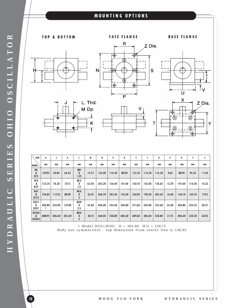
M O U N T I N G O P T I O N S
M O O G F L O - T O R K H Y D R A U L I C S E R I E S
T O P & B O T T O M F A C E F L A N G E B A S E F L A N G E
DIM H J K L M N P R S T U V X Y Z
MODEL mm mm mm mm mm mm mm mm mm mm mm mm mm mm mm
H6 M8& 107.95 69.85 44.45 X 15.75 152.40 114.30 88.90 133.35 114.30 114.30 9.65 88.90 95.25 11.18
H12 1.25
H19 M12& 133.35 76.20 57.15 X 63.50 203.20 136.40 101.60 165.10 152.40 136.65 12.70 101.60 114.30 14.22
H37 1.5
H67 M16& 196.85 117.35 88.90 X 22.10 266.70 203.20 152.40 234.95 190.50 203.20 16.00 165.10 165.10 17.53
H133 2
H251 M20& 304.80 254.00 127.00 X 25.40 406.40 355.60 304.80 371.60 254.00 355.60 25.40 304.80 225.25 20.57
H501 † 2.5
H1002 M24& 488.95 406.40 203.20 X 38.10 660.40 558.80 482.60 609.60 406.40 558.80 31.75 406.40 330.20 26.92
H2002 3
† M o d e l H 2 5 1 / H 5 0 1 H = 3 0 4 . 8 0 H / 2 = 1 5 8 .7 5 B o d y n o t s y m m e t r i c a l - t o p d i m e n s i o n f r o m c e n t e r l i n e i s 1 4 6 . 0 5
H O L L O W K E Y E D M A L E S P L I N E S A E 1 0 B
F E M A L E S P L I N E S A E 1 0 B
S Q U A R E
HYDRAULIC SERIES OHIO OSCILLATOR
M O O G F L O - T O R KH Y D R A U L I C S E R I E S 39
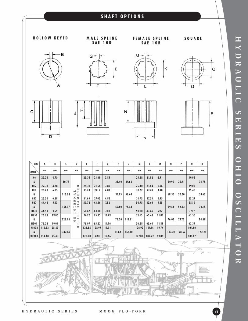
S H A F T O P T I O N S
DIM A B C D E F G H J K L M N P Q R
MODELmm mm mm mm mm mm mm mm mm mm mm mm mm mm mm mm
H6 22.23 4.75 25.35 21.69 3.89 25.38 21.82 3.91 19.05& 80.77 25.40 39.62 30.99 25.91 31.75
H12 22.30 4.78 25.32 21.56 3.86 25.40 21.84 3.96 19.03H19 25.40 6.35 31.70 27.15 4.88 31.72 27.28 4.90 25.40& 110.74 31.75 56.64 68.33 32.00 39.62
H37 25.50 6.38 31.65 27.02 4.85 31.75 27.33 4.95 25.27H67 44.48 9.53 50.72 43.56 7.82 50.75 43.64 7.85 38.10& 156.97 50.80 75.44 59.44 52.32 73.15
H133 44.53 9.55 50.67 43.30 7.80 50.80 43.69 7.92 37.97H251 76.23 19.05 76.12 65.35 11.79 76.15 65.48 11.81 63.50& 226.06 76.20 118.11 76.02 77.72 74.68
H501 76.28 19.01 76.07 65.23 11.76 76.28 65.61 11.89 63.37H1002 114.33 25.40 126.85 108.97 19.71 126.92 109.14 19.74 101.60
& 342.14 114.81 165.10 127.00 128.52 172.21H2002 114.48 25.43 126.80 MAX 19.66 127.00 109.22 19.81 101.47
NO INTERNAL
RELIEF DIAMETER

HYDRAULIC SERIES OHIO OSCILLATOR
40
P O S I T I O N I D E N T I F I C A T I O N & P O R T I N G
M O O G F L O - T O R K H Y D R A U L I C S E R I E S
The following identification codes are used to specify
the location of cushions, cushion adjustments, side ports
and mountings.
SURFACE IDENTIFICATION
MS1 - Front surface or face - bearing cap side
MS2 - Bottom surface - opposite keyway when actuator is at mid-rotation (applies to standard keyway location only)
MS3 - Back surface - opposite of bearing cap side
MS4 - Top surface - opposite bottom surface
S t a n d a r d a n d o p t i o n a l p o r t c o n f i g u r a t i o n s f o r O h i o O s c i l l a t o r h y d r a u l i c r o t a r y a c t u a t o r s .
P O R T S - H Y D R A U L I C R O T A R Y A C T U A T O R S
EXTERNA L STROKE ADJUSTORS SIDE PORTRECOMMENDED MAXIMUM PORT SIZE* MAXIMUM PORT SIZE*
STANDARD TUBE SIZEMODEL BSPP PORT O.D. (mm) BSPP BSPP
H6G 1/4 - 19 4.76 G 1/8-28 G 1/8-28H12
H19G 1/4 - 19 6.35 G 1/4-19 G 1/8-28H37
H67G 1/2 - 14 15.9 G 1/2-14 G 3/8-19H133
H251G 3/4 - 14 19.1 G 3/4-14 G 1/2-14H501
H1002G 1-11 25.4 G 1-11 G 3/4-14H2002
CYLINDER END IDENTIFICATION
Cylinder ends are numerically identified as shown
below. On double rack units the upper left hand
cylinder end is designated as No. 1. Continu ing
clockwise, the upper right hand cylinder is No. 2, the
lower right hand cylinder end is No. 3, and the lower
left hand cylinder end is No. 4.
On single rack Hydraulic units the lower rack is used.
The right cylinder end is No. 3 and the left cylinder
end is No. 4.
NOTE: On model H251 the upper rack is used therefore
the right cylinder end is No. 2 and the left
cylinder end is No. 1.
* W h e n u s i n g s i d e p o r t s c o n s u l t f a c t o r y f o r e n v e l o p e d i m e n s i o n a l c h a n g e s t h a t m ay o c c u r .
N O T E : C o n s u l t f a c t o r y f o r s p e c i a l p o r t i n g r e q u i r e m e n t s . S i z e s s h o w n f o re x t e r n a l s t r o ke a d j u s t o r s a n d s i d e p o r t s a r e m a x i m u m s t a n d a r d p o r t s i z e s .

HYDRAULIC SERIES OHIO OSCILLATOR
M O O G F L O - T O R KH Y D R A U L I C S E R I E S 41
H O W T O O R D E R
SERIES H
TORQUEOUTPUT NUMBER
MODEL AT 138 BAR OF RACKS6 138 Nm 1
12 283 Nm 2 19 407 Nm 1 37 881 Nm 2 67 1356 Nm 1
133 2881 Nm 2 251 5423 Nm 1 501 11637 Nm 2
1002 24970 Nm 1 2002 54007 Nm 2
ROTATIONAL ARC100 — 100º 190 — 190º +/-1º280 — 280º 370 — 370º–––- — Other specify
CUSHIONSOO — OmitCL — CCW stroke - right end cap CR — CW stroke - left end cap CB — Both ends of stroke, one each CQ — Four cushions (two rack units only)
NOTE: Cushion needle adjustment faces front (bearing cap side) in standard assembly. Refer to mounting surface call out to specify other orientation. Example 1: two cushions, back facing — CB3; Example 2: four cushions, top and bottom facing — CQ24.
STROKE ADJUSTOR*OO — Omit AIL — Counter-clockwise stroke-right end cap
(0-5º internal), oneAIR — Clockwise stroke left end cap (0-5º internal), one AIB — Both ends of stroke (0-5º internal), each one AIQ — Four internal adjustors (two rack units only) AEL — Counter-clockwise stroke (0-20º external), one AER — Clockwise stroke (0- 20º external), one AEB — Both ends of stroke (0- 20º external), each one AEQ — Four external adjustors (two rack units only)
0-5º ADJUSTORS & ADJUSTABLE CUSHIONSOO — Omit
AICL — Counter-clockwise stroke - right end cap(0-5º internal), one
AICR — Clockwise stroke - left end cap (0-5º internal), one AICB — Both ends of stroke (0-5º internal) each one AICQ — Four internal adjustors & cushions
(two rack units only)
0- 20º ADJUSTORS & FIXED ORIFICE CUSHIONSOO — Omit
AECL — Counter-clockwise stroke - right end cap(0- 20º external), one
AECR — Clockwise stroke - left end cap (0- 20º external), one
AECB — Both ends of stroke (0- 20º external) each one AECQ — Four external adjustors & cushions
(two rack units only)
NOTE: Fixed orifice cushions are sized to decelerate propelling force at speeds slower than 90º/sec only, may not be adequate to decelerate large kinetic or gravitational loads.
NOTE: The letter “X” appearing as a suffix in the model coderequ ires additional information or serial number for complete model identification.
H67 - 190 - AICB - EB - MS1 - SBH - N -
SPECIAL MODIFICATIONS
AB — Air bleeds XT — Special timing XB — Special bearings XM — Special materials XP — Special coating PT — Position
transducer drive LS — Limited switch
MOUNTINGMS1 — Front face mount (bearing cap side) - standard MS2 — Bottom face mount MS3 — Back face mount MS4 — Top face mount MF1 — Front flange mount MF2 — Bottom flange mount MF3 — Back flange mount MF4 — Top flange mount
X — Special configuration
SHAFT CONFIGURATIONRKS — Round, keyed single (standard) RKD — Round, keyed, double RKH — Round, keyed, hollow SBS — Spline (SAE 10B) single SBD — Spline, doubleSBH — Spline, hollow SQS — Square, single SQD — Square, double
X — Special configuration
SEALSN — Nitrile (Buna-N) F — Fluoroelastomer (Viton) X — Special seals
PORTINGEB — End ports, BSPP SB — Side ports, BSPP X — Special configuration
NOTE: Side port position faces bottom (rack side of shaft on single rack units) or top and bottom (on double rack units) in standard assembly. Refer to mounting surface call out to specify other orientation. EXAMPLE: EB1
*NOTE: Models with external stroke adustors, consult factory if air bleeds or side ports are requ ired. Not available on all models

HYDRAULIC H SERIES OHIO OSCILLATOR
42
H E AV Y D U T Y H Y D R A U L I C
M O O G F L O - T O R K H Y D R A U L I C H D S E R I E S
D E S I G N F E A T U R E S
l HEAVY DUTY HYDRAULIC - 207 BAR MAX
l TORQUE RANGE - 113,000 TO 5,650,000 NM@ 207 BAR
l STANDARD ROTATIONS - 90, 180, 270, 360 DEGREES
l RACK & PINION - HIGH MECHANICAL EFFICIENCY
l ZERO LEAKAGE - HIGH VOLUMETRIC EFFICIENCY
l BEARINGS - CUSTOM SELECTED TO APPLICATION
l GEARING - SINGLE TOOTH FULL LOAD CAPACITY
l HOLLOW SHAFT - COMPACT COUPLINGAND ALIGNMENT
l OPERATING TEMPERATURE - -180 TO 930 C
S T A N D A R D O P T I O N S
l ADJUSTABLE CUSHIONS
l TIE ROD OR MILL-TYPE CYLINDERS
l CUSTOM ROTATIONAL ARCS
l CUSTOM MOUNTING ARRANGEMENTS
l CUSTOM SHAFT CONFIGURATION
l CUSTOMER END CAP VALVES AND PORTS
l SELF-CONTAINED POWER UNITS

HYDRAULIC H SERIES OHIO OSCILLATOR
M O O G F L O - T O R KH Y D R A U L I C H D S E R I E S
E N V E L O P E D I M E N S I O N S
TABULATED DIMENSIONS ARE FOR BASE MODEL, STANDARDCONFIGURATION. THE SELECTION OF OPTIONS MAY ALTER ENVELOPEDIMENSIONS. REFER TO OPTIONS SECTION OR CONSULT FACTORYFOR ADDITIONAL INFORMATION.
A B C D E F G H J K
MODEL ROTATIONNUMBER DEGREES cm cm cm cm cm cm cm cm cm cm
1HH
90 102.24180 144.78270 187.33360 229.87
36.83 36.51 18.42 2.54 X 33.97 3.81 74.93 81.92 5.72
1.5HH90 121.92180 170.18270 218.44360 265.43
41.91 41.91 20.32 3.18 X 39.37 3.81 83.82 91.44 5.72
2HH90 134.62
47.63 48.26 24.13 3.81 X 36.83 4.45 95.89 104.78 6.35180 190.50270 246.38360 302.26
3HH90 134.62
51.44 53.34 24.77 2.54 X 40.64 5.08 106.05 116.21 7.62180 190.50270 246.38360 302.26
4HH90 152.40
57.79 59.69 28.58 3.81 X 46.99 5.72 118.75 130.18 8.89180 215.90270 279.40360 342.90
5HH90 157.48
64.14 63.50 31.75 3.81 X 46.99 5.72 127.64 139.07 8.89180 228.60270 299.72360 373.38
6HH90 171.45
66.04 64.77 34.29 4.45 X 54.61 6.35 133.35 146.05 9.53180 251.46270 331.47360 411.48
7HH90 189.23
71.12 67.31 38.10 5.08 X 55.88 6.99 142.24 156.21 10.16180 278.13270 367.03360 454.66
8HH90 193.04
76.20 67.31 40.64 6.35 X 55.88 6.99 148.59 161.93 10.16180 289.56270 386.08360 482.60
9HH90 203.20
81.28 67.31 45.72 6.35 X 46.99 7.62 154.94 170.18 11.43180 307.34270 411.48360 515.62
10HH90 215.9
109.22 71.12 50.80 6.35 X 55.88 7.62 160.02 175.26 11.43180 327.66270 439.42360 551.18
15HH90 259.08
109.22 71.12 55.88 6.35 X 55.88 8.89 190.50 208.28 12.70180 403.86270 548.64360 690.88
20HH90 280.06
93.98 87.63 63.50 6.99 X 87.63 12.70 203.20 228.60 12.70180 418.34270 556.62360 694.99
25HH90 302.18
104.14 90.17 65.58 6.99 X 90.17 15.24 210.82 241.30 12.70180 452.45270 602.97360 753.01
30HH90 321.39
111.76 96.52 73.66 6.99 X 96.52 16.51 220.98 254.00 12.70180 480.97270 640.56360 800.18
40HH90 374.90
132.08 100.33 81.28 7.62 X 100.33 17.78 248.92 284.48 12.70180 566.42270 757.94360 949.43
50HH90 428.40
152.40 100.33 93.98 7.62 X 100.33 20.32 274.32 314.96 12.70180 651.84270 875.28360 1098.70
PER
CUSTOMER
SPEC
IFIC
ATIO
NS PER
CUSTOMER
SPEC
IFIC
ATIO
NS
43

HYDRAULIC SERIES HH OHIO OSCILLATOR
44
T Y P I C A L P E R F O R M A N C E
M O O G F L O - T O R K H Y D R A U L I C H S E R I E S
N O T E : E x c e e d i n g m a x i m u m p r e s s u r e m ay b e d e t r i m e n t a l t o t h e a c t u a t o r a n d m ay r e d u c e t h ec y c l e l i f e . C o n s u l t f a c t o r y f o r a p p l i c a t i o n s w h e r e m a x i m u m p r e s s u r e m ay b e e x c e e d e d .
* O u t p u t To r q u e ( N m) = To r q u e Fa c t o r x O p e r a t i n g P r e s s u r e ( b a r) . E x a m p l e : M o d e l 1 5 H H @ 1 3 8 b a r d e l i v e r s ( 8 1 8 7 x 1 3 8 ) = 1 1 2 9 8 4 8 N m t o r q u e .
TORQUE
MODEL TORQUE*NUMBER FACTOR 69 103 138 172 207
1HH 546 37661 56219 75323 93880 112984
1.5HH 819 56492 84329 112985 140821 169477
2HH 1092 75323 112439 150646 187762 225969
3HH 1637 112985 168658 225969 281643 338954
4HH 2183 150646 224878 301293 375524 451939
5HH 2729 188308 281097 376616 469405 564924
6HH 3275 225969 337317 451939 563286 677908
7HH 3821 263631 393536 527262 657167 790893
8HH 4367 301293 449756 602585 751048 903878
9HH 4912 338954 505975 677909 844930 1016863
10HH 5458 376616 562195 753232 938811 1129848
15HH 8187 564924 843292 1129849 1408216 1694772
20HH 10916 753232 1124390 1506464 1877622 2259696
25HH 13646 941540 1405487 1883080 2347027 2824620
30HH 16375 1129848 1686585 2259696 2816433 3389544
40HH 21833 1506464 2248780 3012929 3755244 4519393
50HH 27291 1883080 2810975 3766161 4694055 5649241
O U T P U T T O R Q U E ( N m ) A T VA R I O U S P R E S S U R E S I N B A R
MODEL DISPLACEMENTMODEL DISPLACEMENT DISPLACEMENT ( L) PER STROKE*
NUMBER FACTOR* 90º 180º 270º 360º
1HH 0.114 10.2 20.4 30.7 40.9
1.5HH 0.151 13.6 27.3 40.9 54.5
2HH 0.189 17.0 34.1 51.1 68.1
3HH 0.303 27.3 54.5 81.8 109.0
4HH 0.416 37.5 75.0 112.4 149.9
5HH 0.530 47.7 95.4 143.1 190.8
6HH 0.606 54.5 109.0 163.5 218.0
7HH 0.719 64.7 129.5 194.2 258.9
8HH 0.871 78.4 156.7 235.1 313.4
9HH 0.946 85.2 170.3 255.5 340.7
10HH 1.060 95.4 190.8 286.2 381.6
15HH 1.476 132.9 265.7 398.6 531.5
20HH 2.196 197.6 395.2 592.8 790.4
25HH 2.536 228.3 456.5 684.8 913.0
30HH 2.990 269.1 538.3 807.4 1076.6
40HH 4.467 402.0 804.0 1206.0 1608.0
50HH 5.186 466.7 933.5 1400.2 1867.0
* D i s p l a c e m e n t ( l i t e r s ) = D i s p l a c e m e n t Fa c t o r x R o t a t i o n a l A r c ( d e g r e e s) . E x a m p l e : 9 M x 2 7 0 º d i s p l a c e s ( . 9 4 6 x 2 7 0 ) = 2 5 5 . 5 L .
MEGATORK SERIES OHIO OSCILLATOR
M O O G F L O - T O R KM E G A T O R K 45
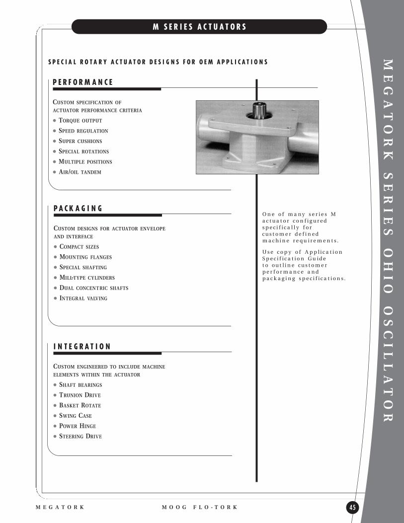
M S E R I E S A C T U A T O R S
O n e o f m a ny s e r i e s M a c t u a t o r c o n f i g u r e d s p e c i f i c a l l y f o r c u s t o m e r d e f i n e d m a c h i n e r e q u i r e m e n t s .
U s e c o p y o f A p p l i c a t i o nS p e c i f i c a t i o n G u i d e t o o u t l i n e c u s t o m e r p e r f o r m a n c e a n d p a c k a g i n g s p e c i f i c a t i o n s .
S P E C I A L R O T A R Y A C T U A T O R D E S I G N S F O R O E M A P P L I C A T I O N S
P E R F O R M A N C E
CUSTOM SPECIFICATION OF
ACTUATOR PERFORMANCE CRITERIA
l TORQUE OUTPUT
l SPEED REGULATION
l SUPER CUSHIONS
l SPECIAL ROTATIONS
l MULTIPLE POSITIONS
l AIR/OIL TANDEM
I N T E G R A T I O N
CUSTOM ENGINEERED TO INCLUDE MACHINE
ELEMENTS WITHIN THE ACTUATOR
l SHAFT BEARINGS
l TRUNION DRIVE
l BASKET ROTATE
l SWING CASE
l POWER HINGE
l STEERING DRIVE
P A C K A G I N G
CUSTOM DESIGNS FOR ACTUATOR ENVELOPE
AND INTERFACE
l COMPACT SIZES
l MOUNTING FLANGES
l SPECIAL SHAFTING
l MILL-TYPE CYLINDERS
l DUAL CONCENTRIC SHAFTS
l INTEGRAL VALVING

MEGATORK
46
H Y D R A U L I C R O T A R Y A C T U A T O R
M O O G F L O - T O R K M E G A T O R K
D E S I G N F E A T U R E S
l HEAVY DUTY HYDRAULIC - 207 BAR
l TORQUE RANGE - 113000 TO 5,650,000 NM
l STANDARD ROTATIONS - 90, 180, 360 DEGREES
l RACK & PINION - HIGH MECHANICAL EFFICIENCY
l ZERO LEAKAGE - HIGH VOLUMETRIC EFFICIENCY
l PISTON SEALS - PRE-LOADED LIP SEALS
l GEARING - SINGLE TOOTH FULL LOAD CAPACITY
l HOLLOW SHAFT - ELIMINATES COSTLY COUPLING
l COMPACT DESIGN - HIGHEST TORQUE PER CU. FT. OF SPACE
l TEMPERATURE RANGE - -18 TO 93O C
O P T I O N A L F E A T U R E S
l ADJUSTABLE CUSHIONS
l TIE ROD OR MILL TYPE CYLINDERS
l CUSTOM ROTATIONAL ARCS
l CUSTOM MOUNTING ARRANGEMENTS
l CUSTOM END CAP VALVES AND PORTS
l SELF CONTAINED HYDRAULIC POWER UNITS
l CUSTOM MOUNTINGS
l CUSTOM SHAFT CONFIGURATION
l CUSTOM DESIGNS FOR PRESSURE, TORQUE, AND DIMENSIONAL REQUIREMENTS
l CUSTOM CORROSION PROTECTION
l DESIGNS FOR 4:1 PRESSURE VESSEL
SAFETY FACTOR
Cylinder Heads l HEAVY STEEL SECTION
l I.D. STATIC SEAL TO PREVENTSEAL EXTRUSION
Low Pressure Relief Valve l PROTECT HOUSING FROM
OVER PRESSURIZATION
l SIGNALS NEED FOR DYNAMICSEAL REPLACEMENT
Rack Bearings l SUPPORT FULL RACK LOAD
l MINIMIZE BACKLASH
Racks l HEAT TREATED HIGH
STRENGTH ALLOY STEEL
Tie Rods l HIGH STRENGTH
ALLOY STEEL
l PRE-STRESSED
Bearing Cap l PILOTED STEEL OR
DUCTILE IRON
Bearings l PRECISION BEARINGS
l SUBSTANTIAL EXTERNAL LOAD CAPACITY
Pinion l SINGLE KEYED HOLLOW SHAFT
l HEAT TREATED ALLOY STEEL
Housing l FABRICATED STEEL
OR DUCTILE IRON Cylinder Tubesl CUSTOM MATERIAL
Pistonsl PATENTED FLOATING DESIGN
l SELF-ALIGNING

MEGATORK
M O O G F L O - T O R KM E G A T O R K 47
M E G A T O R K A P P L I C A T I O N
FLO-TORK Megatork actuators are designed to meet the needs of each individual application. Because of this we
have included the following information sheet to help us in assisting you in sizing the correct actuator for your
application. Please fill in the data sheet and forward it to us for review. We will contact you to discuss the specifics
of your application.
COMPANY:
ADDRESS:
CITY: ZIP:
PHONE NUMBER: FAX NUMBER:
NAME: E-MAIL:
A P P L I C A T I O N I N F O R M A T I O N :
TORQUE REQUIRED:
ROTATION REQUIRED:
OPERATING PRESSURE (BAR):
DIMENSIONAL DATA: UNITS OF MEASURE: METRIC:
A: B: C:
F: G: J:
L: M:
Please fill in the envelope dimensions that you requ ire for your specific application to assist us in sizing your actuator.
A P P L I C A T I O N D E S C R I P T I O N :

MEGATORK
48
T Y P I C A L P E R F O R M A N C E
M O O G F L O - T O R K M E G A T O R K
* O u t p u t To r q u e ( N m) = To r q u e Fa c t o r x O p e r a t i n g P r e s s u r e ( b a r) E x a m p l e : M o d e l 9 M @ 1 0 3 b a r d e l i v e r s (4 9 1 2 x 1 0 3 ) = 5 0 5 9 7 5 N m t o r q u e .
MODEL TORQUEOUTPUT TORQUE (Nm) @ VARIOUS PRESSURES IN BAR*
NUMBER FACTOR* 69 103 138 172 207
1M 546 37661 56219 75323 93880 112984
1.5M 819 56492 84329 112985 140821 169477
2M 1092 75323 112439 150646 187762 225969
3M 1637 112985 168658 225969 281643 338954
4M 2183 150646 224878 301293 375524 451939
5M 2729 188308 281097 376616 469405 564924
6M 3275 225969 337317 451939 563286 677908
7M 3821 263631 393536 527262 657167 790893
8M 4367 301293 449756 602585 751048 903878
9M 4912 338954 505975 677909 844930 1016863
10M 5458 376616 562195 753232 938811 1129848
15M 8187 564924 843292 1129848 1408216 1694772
20M 10916 753232 1124390 1506464 1877622 2259696
25M 13646 941540 1405487 1883080 2347027 2824620
30M 16375 1129848 1686585 2259696 2816433 3389544
40M 21833 1506464 2248780 3012929 3755244 4519393
50M 27291 1883080 2810975 3766161 4694055 5649241
MODEL DISPLACEMENTMODEL DISPLACEMENT DISPLACEMENT ( L) PER STROKE*
NUMBER FACTOR* 90º 180º 270º 360º
1M 0.114 10.2 20.4 30.7 40.9
1.5M 0.151 13.6 27.3 40.9 54.5
2M 0.189 17.0 34.1 51.1 68.1
3M 0.303 27.3 54.5 81.8 109.0
4M 0.416 37.5 75.0 112.4 149.9
5M 0.530 47.7 95.4 143.1 190.8
6M 0.606 54.5 109.0 163.5 218.0
7M 0.719 64.7 129.5 194.2 258.9
8M 0.871 78.4 156.7 235.1 313.4
9M 0.946 85.2 170.3 255.5 340.7
10M 1.060 95.4 190.8 286.2 381.6
15M 1.476 132.9 265.7 398.6 531.5
20M 2.196 197.6 395.2 592.8 790.4
25M 2.536 228.3 456.5 684.8 913.0
30M 2.990 269.1 538.3 807.4 1076.6
40M 4.467 402.0 804.0 1206.0 1608.0
50M 5.186 466.7 933.5 1400.2 1867.0
* D i s p l a c e m e n t ( l i t e r s ) = D i s p l a c e m e n t Fa c t o r x R o t a t i o n a l A r c ( d e g r e e s) . E x a m p l e : 9 M x 2 7 0 º d i s p l a c e s ( . 9 4 6 x 2 7 0 ) = 2 5 5 . 5 L .
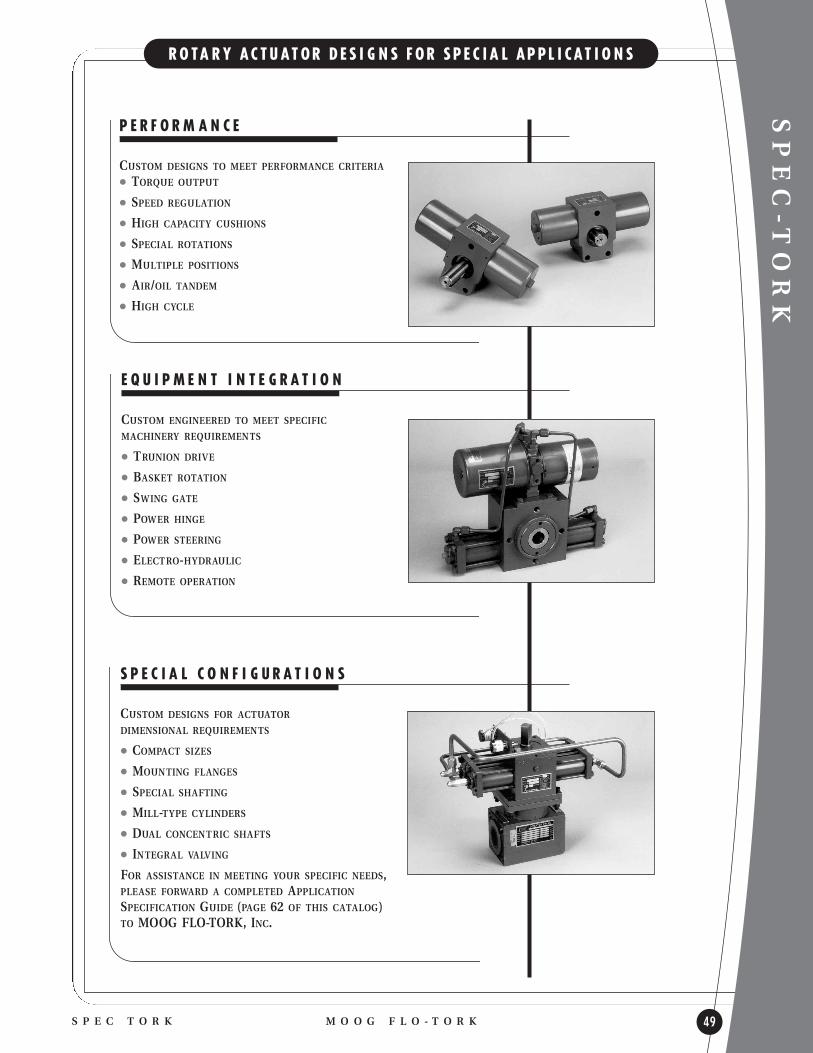
SPEC-T
ORK
M O O G F L O - T O R KS P E C T O R K 49
R O TA R Y A C T U A T O R D E S I G N S F O R S P E C I A L A P P L I C A T I O N S
P E R F O R M A N C E
CUSTOM DESIGNS TO MEET PERFORMANCE CRITERIA
l TORQUE OUTPUT
l SPEED REGULATION
l HIGH CAPACITY CUSHIONS
l SPECIAL ROTATIONS
l MULTIPLE POSITIONS
l AIR/OIL TANDEM
l HIGH CYCLE
S P E C I A L C O N F I G U R A T I O N S
CUSTOM DESIGNS FOR ACTUATOR
DIMENSIONAL REQUIREMENTS
l COMPACT SIZES
l MOUNTING FLANGES
l SPECIAL SHAFTING
l MILL-TYPE CYLINDERS
l DUAL CONCENTRIC SHAFTS
l INTEGRAL VALVING
FOR ASSISTANCE IN MEETING YOUR SPECIFIC NEEDS,PLEASE FORWARD A COMPLETED APPLICATIONSPECIFICATION GUIDE (PAGE 62 OF THIS CATALOG) TO MOOG FLO-TORK, INC.
E Q U I P M E N T I N T E G R A T I O N
CUSTOM ENGINEERED TO MEET SPECIFIC
MACHINERY REQUIREMENTS
l TRUNION DRIVE
l BASKET ROTATION
l SWING GATE
l POWER HINGE
l POWER STEERING
l ELECTRO-HYDRAULIC
l REMOTE OPERATION
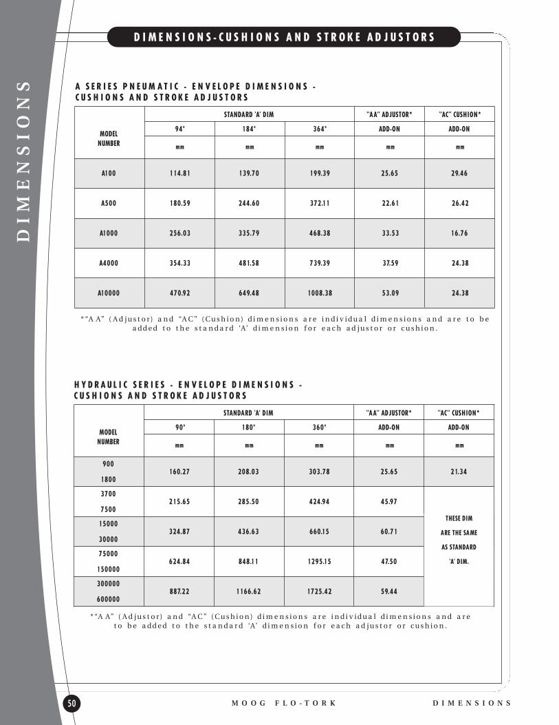
DIMENSIONS
50
D I M E N S I O N S - C U S H I O N S A N D S T R O K E A D J U S T O R S
M O O G F L O - T O R K D I M E N S I O N S
* “A A” ( A d j u s t o r) a n d “A C ” ( C u s h i o n) d i m e n s i o n s a r e i n d i v i d u a l d i m e n s i o n s a n d a r e t o b e a d d e d t o t h e s t a n d a r d ‘A’ d i m e n s i o n f o r e a c h a d j u s t o r o r c u s h i o n .
* “A A” ( A d j u s t o r) a n d “A C ” ( C u s h i o n) d i m e n s i o n s a r e i n d i v i d u a l d i m e n s i o n s a n d a r e t o b e a d d e d t o t h e s t a n d a r d ‘A’ d i m e n s i o n f o r e a c h a d j u s t o r o r c u s h i o n .
H Y D R A U L I C S E R I E S - E N V E L O P E D I M E N S I O N S - C U S H I O N S A N D S T R O K E A D J U S T O R S
STANDARD ‘A’ DIM “A A” ADJUSTOR* “AC” CUSHION*
MODEL94º 184º 364º ADD-ON ADD-ON
NUMBER mm mm mm mm mm
A100 114.81 139.70 199.39 25.65 29.46
A500 180.59 244.60 372.11 22.61 26.42
A1000 256.03 335.79 468.38 33.53 16.76
A4000 354.33 481.58 739.39 37.59 24.38
A10000 470.92 649.48 1008.38 53.09 24.38
STANDARD ‘A’ DIM “A A” ADJUSTOR* “AC” CUSHION*
MODEL90º 180º 360º ADD-ON ADD-ON
NUMBER mm mm mm mm mm
900160.27 208.03 303.78 25.65 21.34
1800
3700215.65 285.50 424.94 45.97
7500
15000324.87 436.63 660.15 60.71
30000
75000624.84 848.11 1295.15 47.50
150000
300000887.22 1166.62 1725.42 59.44
600000
THESE DIM
ARE THE SAME
AS STANDARD
‘A’ DIM.
A S E R I E S P N E U M A T I C - E N V E L O P E D I M E N S I O N S - C U S H I O N S A N D S T R O K E A D J U S T O R S

UNIT MASS
M O O G F L O - T O R KU N I T M A S S 51
U N I T M A S S
MODEL94º 184º 364º
NUMBER Kg Kg Kg
A100 1.36 1.36 1.81
A500 3.63 4.08 5.44
A1000 6.35 7.26 9.98
A4000 21.32 24.95 33.11
A10000 43.09 48.99 61.69
A S E R I E S P N E U M A T I C
MODEL94º 184º
NUMBER Kg Kg
P300 1.81 2.27
P1000 4.08 5.90
P2000 7.71 11.34
P4000 19.05 24.95
P8000 26.76 34.47
P10000 32.21 41.73
P S E R I E S P N E U M A T I C
MODEL90º 180º 360º
NUMBER Kg Kg Kg
900 3.63 4.54 4.99
1800 4.08 4.99 5.44
3700 8.16 9.07 11.79
7500 9.98 10.89 12.70
15000 27.67 29.03 33.57
30000 35.38 36.74 44.0
75000 122.47 130.64 146.51
150000 149.69 163.75 180.08
300000 427.74 459.50 527.08
600000 518.92 583.33 717.60
H Y D R A U L I C S E R I E S
N O T E : A p p r o x i m a t e w e i g h t s s h o w na b o v e a r e b a s e d
o n s t a n d a r d m o d e l s .

DIMENSIONS OHIO OSCILLATOR
52
D I M E N S I O N S - C U S H I O N S A N D S T R O K E A D J U S T O R S
M O O G F L O - T O R K D I M E N S I O N S
* “A A” ( A d j u s t o r) a n d “A C ” ( C u s h i o n) d i m e n s i o n s a r e i n d i v i d u a l d i m e n s i o n s a n d a r e t o b e a d d e d t o t h e s t a n d a r d ‘A’ d i m e n s i o n f o r e a c h a d j u s t o r o r c u s h i o n .
C o n s u l t Fa c t o r y C o n s u l tFa c t o r y
A S E R I E S - E N V E L O P E D I M E N S I O N S - C U S H I O N S A N D S T R O K E A D J U S T O R S
STANDARD ‘A’ DIM “A A” ADJUSTOR* “A A” CUSHION*
MODEL100º 190º 280º 370º 100º 190º 280º 370º NON-CRUSH CRUSH
NUMBER mm mm mm mm mm mm mm mm mm mm
A6.2 287.53 317.50 407.16 436.88 22.10 22.10 22.10 22.10 41.15 52.83
A6.3 290.83 320.80 410.21 440.18 20.57 20.57 20.57 20.57 38.10 52.83
A19.3 336.55 376.43 499.11 542.04 20.57 20.57 20.57 19.05 38.10 52.83
A19.4 339.09 378.97 501.40 546.10 19.30 19.30 19.30 17.02 35.56 52.83
A67.4 428.50 484.33 656.59 712.47 19.30 19.30 17.02 17.02 35.56 52.83
A67.6 440.44 496.32 670.05 725.93 20.57 20.57 17.27 17.27 23.88 52.83
A250.6 653.03 835.41 1075.18 1257.81
A250.8 653.03 835.41 1075.18 1257.81
A250.10 762.00 866.65 1184.15 1336.55
* “A A” ( A d j u s t o r) d i m e n s i o n i s t o b e a d d e d t o t h e s t a n d a r d ‘A’ d i m e n s i o n f o r e a c h a d j u s t o r .
H S E R I E S - E N V E L O P E D I M E N S I O N S - C U S H I O N S A N D S T R O K E A D J U S T O R S
STANDARD ‘A’ DIM “A A” ADJUSTOR* “A A” CUSHION*
MODEL100º 190º 280º 370º ADD-ON CUSHIONS
NUMBER mm mm mm mm mm
H6205.99 265.94 325.88 385.51 37.34
H12
H19260.10 339.85 419.61 499.37 46.23
H37
H67329.95 441.71 553.47 665.99 51.05
H133
H251621.03 833.88 1046.75 1257.05 48.26
H501
H10021006.09 1379.47 1914.65 2093.98 59.69
H2002
T H E S E D I M .A R E T H E S A M E
A S S T A N D A R D
‘A’ D I M .
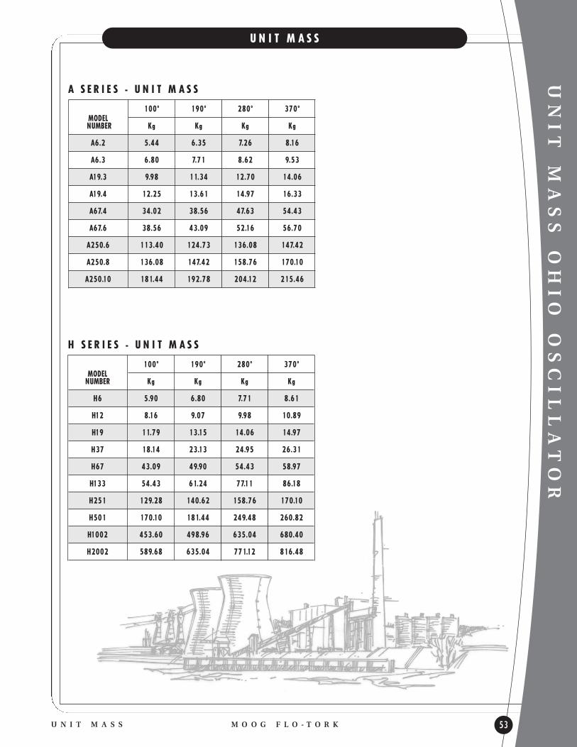
UNIT MASS OHIO OSCILLATOR
M O O G F L O - T O R KU N I T M A S S 53
U N I T M A S S
MODEL100º 190º 280º 370º
NUMBER Kg Kg Kg Kg
A6.2 5.44 6.35 7.26 8.16
A6.3 6.80 7.71 8.62 9.53
A19.3 9.98 11.34 12.70 14.06
A19.4 12.25 13.61 14.97 16.33
A67.4 34.02 38.56 47.63 54.43
A67.6 38.56 43.09 52.16 56.70
A250.6 113.40 124.73 136.08 147.42
A250.8 136.08 147.42 158.76 170.10
A250.10 181.44 192.78 204.12 215.46
A S E R I E S - U N I T M A S S
MODEL100º 190º 280º 370º
NUMBER Kg Kg Kg Kg
H6 5.90 6.80 7.71 8.61
H12 8.16 9.07 9.98 10.89
H19 11.79 13.15 14.06 14.97
H37 18.14 23.13 24.95 26.31
H67 43.09 49.90 54.43 58.97
H133 54.43 61.24 77.11 86.18
H251 129.28 140.62 158.76 170.10
H501 170.10 181.44 249.48 260.82
H1002 453.60 498.96 635.04 680.40
H2002 589.68 635.04 771.12 816.48
H S E R I E S - U N I T M A S S

ENGINEERING
54
A P P L I C A T I O N E X A M P L E S , R O T A R Y M O T I O N
M O O G F L O - T O R K E N G I N E E R I N G
This is important because energy bu ilt up during uniform acceleration must be absorbed during deceleration by a bu ild up of back pressure in the actuator cylinder.
Since energy in must equal the energy out, if the rotaryactuator is used to decelerate the load, any reduction indeceleration time will result in increased back pressurewhich may be damaging to the rotary actuator andother system components. In all circu its this back pressure must be absorbed into the existing system.
Consider that acceleration energy equals torque timesthe angle of acceleration (Taθa). In terms of kinetic energy it is:
Ek = Jω2
2
The deceleration torque requ ired to stop the load is kinetic energy divided by the angle of deceleration:
Td = Jω2
2θdSince deceleration energy must equal acceleration energy (Tdθd=Taθa) and actuator pressure is proportional to torque, we can set up a simple example of angular travel and pressure.
EXAMPLE: If a load is uniformly accelerated thru 100º rotation at 69 bar, you can determine the deceleration pressure to stop the load in 80º by the following:
100º x 69=Pressure to decelerate=86 bar80º
ANOTHER EXAMPLE: Uniformly accelerate a load thru 165ºrotation at 34.5 bar, then stop the motion within the last 15º of rotation:
165º x 34.5 bar=Pressure to decelerate=379 bar15º
Deceleration pressure of 379 bar to dissipate the kinetic energy during the last 15º of rotation may prove to be destructive to the system.
Another example illustrates the use of flow controlvalves to control output flow. A mass acceleratedthrough 40º at 138 bar, then moving at constant speedfor 125º, will generate a destructive deceleration pressureof 368 bar to dissipate the kinetic energy within the last15º of rotation.
40º x 138=Pressure to decelerate=368 bar15º
In addition, since it is difficult and in many casesimpractical to remove system pressure during deceleration, one must consider the torque developed by the system pressure while driving the load throughthe deceleration distance (rotation) in addition to thekinetic energy already existing.
The optional MOOG FLO-TORK built-in cushions aredesigned to help decelerate the load during the last 15ºof rotation. The deceleration pressure should not exceedthe rated pressure of the rotary actuator model selected.
The torque requ ired to put a load into motion by arotary actuator is the sum of the static torque, thedynamic torque and the gravitational torque. Statictorque is the torque of friction, dynamic torque is thetorque requ ired to accelerate to desired speed and gravitational torque is the torque necessary to lift aweight against gravity. It is suggested that an actuatorwith reserve capacity of at least 20 percent be selected to accommodate variations within the system.
ROTATION IN VERTICAL PLANEThe maximum torque requ ired to rotate the weight (W)thru an angle Ø in a vertical plane will occur when thearm is horizontal. This torque is determined by theequation: T = Wr. If the arm mass is significant its effecton the torque requ ired must be calculated.
As the arm approaches vertical the requ ired torque becomes less because the arm length (r) becomes shorter as a function of the sine of the angle. The torque requ ired at any position can be determined by: T = Wr sin Ø
HORIZONTAL ROTATION OF SUPPORTED WEIGHT
The previous example does not include any considerations for friction. Friction Torque (Tf) canbe determined by the product of the weight (W), the coefficient of friction (Cf) and the bearing radius (rb).
Tf = W Cf rb
NOTE: (W) should include the weight of the turntable as well as the load. Torque (Tf) requ ired to overcome friction must be added to the acceleration torque (Ta) prior to selecting the proper rotary actuator model. The friction torque can be subtracted from the deceleration torque if desired.
HORIZONTAL ROTATION OF UNSUPPORTED WEIGHT
The torque (Ta) requ ired to accelerate (rotate) unsupported weight in ahorizontal plane can be determined by:
Ta = J O<
Where J = Wr2g
Angular acceleration (α) is usually uniform and can bedetermined by:
α = (ω2 - ω1) Where ω�= (θ2 - θ1)(t2 -t1) (t2 -t1)
CAUTION: See Caution note on Page 31.
DECELERATIONDeceleration torque is often the least understood and in many cases the most important requ irement to be considered.
The time requ ired to decelerate the load within a givenangle of rotation should usually be longer than the timerequired to accelerate the same load to a requ ired speed.
Bearing
Decel. @ 379 bar
Decel. @ 368 bar
Accel. @ 138 bar
Accel.@ 34.5 bar
Constant Speed 125º

r -Arc length equal to radius
1 revolution = 3600 = 2π radians
1 radian = 57.30
ENGINEERING
M O O G F L O - T O R KE N G I N E E R I N G 55
Q U A N T I T I E S A N D F O R M U L A S F O R R O T A R Y M O T I O N
TORQUE is a force that produces rotation of a shaft.
It is measured by the product of the force (F) and the
perpendicular distance from the line of action of the
force to the centerline of rotation (r).
T = F r
ROTATION results when an unbalanced torque acts on
a body producing an angular acceleration. The torque
to accelerate is the product of the body’s moment of
inertia about its axis of rotation (J) and the angular
acceleration (α).
T = J α�
MOMENT OF INTERIA of a body is determined by the
distribution of its mass about the axis of rotation. It
tends to resist any change in angular velocity.
J = mr2 See table page 56
ANGULAR ACCELERATION is the rate of change of
angular velocity and is expressed in radians per second
per second. If angular velocity changes from ωO at
time O to ωt at time t in time (t), the average angular
acceleration is:
α = ωt - ωOt
ANGULAR VELOCITY is the rate of angular rotation
about an axis and is expressed in radians per second.
If a body moves through a rotation of θ radians in a
time of t seconds, the average angular velocity is:
ω�= θ
t
ANGULAR ROTATION is the arc traveled in rotary
motion and can be expressed in degrees, revolutions
or radians. One radian is the angle defined from the
center of a circle by an arc that is equal in length to
the radius.
KINETIC ENERGY is the energy of a mass in motion.
It is a function of the moment of inertia (J) and the
square of the angular velocity (ω) expressed as:
Ek = 1/2 J ω2
EQUATIONS FOR ANGULAR MOTION are analogous
to those for linear motion:
v = at s = 1/2at2 v2 = 2as
ω = αt θ�=�1/2αt2 ω2 = 2αθ
If vo and ωo denote the initial linear and angular
velocity then
v = vo + at s = vot + 1/2at2 v2 = vo2 + 2as
ω = ωo + αt θ�=�ωot + 1/2αt2 ω2 = ωo2 + 2αθ
ANALOGOUS LINEAR & ANGULAR QUANTITIES
Linear Displacements s s = θr Angular Displacement θ
Linear Velocity v v = ωr Angular Velocity ω
Linear Acceleration a a = αr Angular Acceleration α
Mass (Inertia) m J = mr2 Moment of Inertia J
Force F T = Fr Torque T
Linear: F = ma Ek = 1/2mv2 Work = Fs Power = Fv
Angular: T = Jα Ek = 1/2Jω2 Work = Tθ Power = Tω
DEFINITIONSSymbol Units of Measure
a = Linear Acceleration m/s2
Cf = Friction Coefficient dimensionlessCT = Torque Coefficient Nm/barEc = Cushion Energy Joules Ef = Friction Energy JoulesEg = Gravitational Energy JoulesEk = Kinetic Energy JoulesEp = Propelling Energy JoulesET = Total Energy JoulesF = Force Ng = Acceleration due to Gravity 9.81 m/s2
J = Moment of Inertia kg (m)2
m = Mass = W/g kgP = Pressure barr = Radius mra = Radius Arm Length mrb = Radius of Bearing ms = Linear Displacement mT = Torque NmTa = Torque of Acceleration NmTd = Torque of Deceleration NmTf = Torque of Friction NmTp = Torque of Propulsion Nmt = Time secv = Linear Velocity m/sW = Weight Nα = Angular Acceleration rad/sec2
θ = Angular Displacement radθa = Angle of Acceleration radθd = Angle of Deceleration radØ = Angle of Arm to Vertical degØ = Average Angle from Vertical degω = Angular Velocity rad/sec
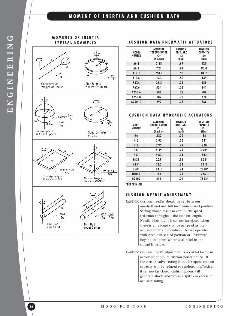
ENGINEERING
56
M O M E N T O F I N E R T I A A N D C U S H I O N D A T A
M O O G F L O - T O R K E N G I N E E R I N G
ACTUATOR CUSHION CUSHIONMODEL TORQUE FACTOR DECEL A RC CAPACITYNUMBER CT θd Ec
(Nm/Bar) (Rad) (Nm)
A6.2 3.28 .67 37.8 A6.3 7.21 .67 83.0A19.3 9.83 .50 84.7 A19.4 17.3 .50 149 A67.4 24.3 .36 150A67.6 55.1 .36 341A250.6 104 .28 506A250.8 187 .28 720A250.10 292 .28 844
M O M E N T S O F I N E R T I A T Y P I C A L E X A M P L E S C U S H I O N D A T A P N E U M A T I C A C T U A T O R S
ACTUATOR CUSHION CUSHIONMODEL TORQUE FACTOR DECEL A RC CAPACITYNUMBER CT θd Ec
(Nm/bar) (rad) (Nm)H6 .982 .20 54 H12 2.05 .20 54*H19 2.95 .29 220 H37 6.39 .29 220* H67 9.83 .34 802H133 20.9 .34 802* H251 39.3 .24 2110 H501 84.3 .24 2110*H1002 181 .21 7863 H2002 391 .21 7863*
*PER CUSHION
C U S H I O N D A T A H Y D R A U L I C A C T U A T O R S
C U S H I O N N E E D L E A D J U S T M E N T
CAUTION: Cushion needles should be set between
one-half and one full turn from seated position.
Setting should result in continuous speed
reduction throughout the cushion length.
Needle adjustment is set too far closed when
there is an abrupt change in speed as the
actuator enters the cushion. Never operate
with needle in seated position or unscrewed
beyond the point where seal relief in the
thread is visible.
CAUTION: Cushion needle adjustment is a crucial factor in
achieving optimum cushion performance. If
the needle valve setting is too far open, cushion
capacity will be reduced or rendered ineffective;
if set too far closed, cushion action will
generate shock and pressure spikes in excess of
actuator rating.

ENGINEERING
M O O G F L O - T O R KE N G I N E E R I N G 57
C U S H I O N C A P A C I T Y A N D S I Z I N G
VERTICAL ROTATIONAL DECELERATIONA material handling rollover mechanism transfers a 45 kgmachine part through 180º in a vertical plane from a 9 o ’clock to a 3 o’clock position. The radius arm to the partgrippers is 1.02 m and the effective weight and radius of the arms and grippers can be approximated by two1.02 m long rods weighing 32 kg a piece. Rotational velocity of the mechanism as it enters the cushion deceleration arc is 40º/sec or (40÷57.3) 0.70 rad/sec. A Model 15000 actuator operating at 138 bar has been selectedto propel the load.
KINETIC ENERGY Ek = 1/2 J ω2
Moment of Inertia J = Jarm + JloadJarm = 2Mara2 = 2 (32 kg) (1.02 m)2 = 22.2 kg m2
3 3
Jload = MIrI2 = (45 kg) (1.02 m)2 = 47 kg m2
J = Jarm + Jload = 22.2 + 47 = 69.2 kg m2
Ek = 1/2 J ω2 = 1/2 (69.2 kg m2) (.70 rad/sec)2
= 16.9 kg m2 = 16.9 Jouless2
PROPELLING ENERGY Ep = Pp Ct θd
Torque Factor (Ct) for Model 15000 (8.19 Nm/bar)
Deceleration Arc (θd) for Model 15000 (.34 rad)
Ep = Pp Ct θd = (138 bar) (8.19 Nm/bar) (.34 rad) = 384 Joules
GRAVITATIONAL ENERGY Eg = WraθdsinØ
Wra = 9.81 m [(45 kg)(1.02 m) + 2(32 kg)(1/2)(1.02m)] = 770 Nms2
Deceleration Arc (Ød) for Model 15000 (0.34 rad or 19.6o)
Ø = 1/2 (Øenter + Øend)
Øenter = Øend - θd= 90o - 19.6o = 70.4o
Ø = 1/2 (70.4o + 90o) = 80.2o
sin Ø = .99
Eg = WraθdsinØ = (770 Nm)(.34 rad)(.99) = 259 Joules
TOTAL ENERGY Et = Ek + Ep ± EgEt = 16.9 + 384 + 259 Nm = 659.9 Joules
Total energy to be absorbed in the example is 659.9 Joules.The cushion capacity of Model 15000 is 711 Joules. This is adequate to meet the deceleration requ irement.
When the energy developed exceeds the capacity of the cushion, consider the following:
l REDUCE WEIGHT OF OBJECT IN MOTIONl REDUCE ROTATIONAL VELOCITYl EMPLOY EXTERNAL SHOCK ABSORBERSl ADD PROPORTIONAL HYDRAULICS TO THE CIRCUIT TO
REDUCE PROPELLING ENERGY DURING DECELERATION.
CAUTION: Cushion needle adjustment is a crucial factor in achieving optimum cushion performance. If the needle valve setting is too far open, cushion capacity will be reduced or rendered ineffective; if set too tight, cushion action will generate shock and pressure spikes in excess of actuator rating.
High rotational velocity and/or large mass in rotarymotion can cause damaging impact at the end ofstroke. Deceleration and absorption of rotating systemenergy can be achieved with cushions, external shockabsorbers or flu id circu it devices which reduce speed asthe actuator approaches the end of travel.
Cushions are the simplest design alternative, but consideration must be given to the cushion energyabsorption capacity. Exceeding rated cushion capacitycan reduce actuator life or result in severe actuatordamage. To determine if a cushion is su itable for theapplication, calculate the total energy that must beabsorbed and compare with the cushion capacity rating.
ENERGY OF APPLICATIONEk = Energy of mass in motion (kinetic energy)Ek = 1/2 J ω2
Ep = Propelling energy of actuatorEp = PpCtθdEg = Gravitational energy of lifting or lowering weightEg = WraθdsinØ
Total Energy, where: Et = Ek + Ep ± Eg Eg is added if weight is falling or Eg is subtracted ifweight is rising
NOTE: If weight is rotating in horizontal plane, the gravitational energy is zero.
HORIZONTAL ROTATIONAL DECELERATIONTwo 22.6 kg parts are positioned diametrically opposedon a 68 kg lb rotary transfer table which swingsthrough 180º in a horizontal plane. The table radius is1.27 m in and the radius to the parts is 1.02 mRotational velocity of the table as it enters the cushiondeceleration arc is 80º/sec or (80÷57.3) 1.40 rad/sec. Amodel 3700 actuator operating at 103 bar has beenselected to propel the load.
KINETIC ENERGY Ek = 1/2 J ω2
Moment of Inertia J = Jtable + JloadJtable = Mtrt2 = (68 kg) (1.27 m)2 = 54.8 kg m2
2 2
Jload = MIrI2 = (22.6 + 22.6 kg) (1.02 m)2 = 47 kg m2
J = Jtable + Jload = 54.8 + 47 = 101.8 kg m2
Ek = 1/2 J ω2 = 1/2 (101.8 kg m2) (1.40 rad/sec)2
= 99.7 kgm2 = 99.7 Joules
s2
PROPELLING ENERGY Ep = Pp Ct θd
Torque Factor (Ct) for Model 3700 (2.02 Nm/bar)Deceleration Arc (θd) for Model 3700 (.33 radians) Ep = Pp Ct θd = (103.4 bar) (2.02 Nm/bar) (0.33 radians)
= 68.9 Joules
GRAVITATIONAL ENERGY Eg = 0 for horizontal rotation
TOTAL ENERGY Et = Ek + Ep ± EgEt = 99.7 + 68.9 + 0 Nm = 168.6 Joules
Total energy to be absorbed in the example is 168.6 Joules. The cushion capacity of Model 3700 when properly adjusted is 188.7 Joules. This is adequate to meet the deceleration requ irement.
Øend = 90o @ 3 o’clock
Øenter =
70.4o
θd =19.6o

ENGINEERING
58
L I N E A R D R I V E
M O O G F L O - T O R K E N G I N E E R I N G
GENTLE DECELERATIONYou have the maximum mechanical advantage where you need it . . . at the end of the travel. Deceleration is a “mirror” reflection of acceleration and the load will beslowed down by the rotary actuator automatically.
HIGH SPEED -SMOOTH SPEED CONTROLControlled acceleration and deceleration . . . with the MOOG FLO-TORK rotary actuator rotating at a constantspeed. You can go faster and smoother using rotary actuators than with any other method.
GENTLE ACCELERATIONYou have the maximum mechanical advantage where youneed it . . . at the beginning of the travel. Force arrowshows maximum force in the direction of start-up to getyou started faster.
SPEEDMaximum velocity is when the load is halfway to its destination. Smooth acceleration to that point . . . thensmooth deceleration.
LINEAR DRIVE WITH MOOG
FLO-TORK ROTARY ACTUATORSUSING HARMONIC MOTION
The advantages of using rotary actuators, combinedwith harmonic -motion-producing linkages, compared to the straight line cylinders, are derived from the principle of converting a constant speed rotatingmotion to a sinusoidal (sine-wave) motion which produces maximum linear force where needed for acceleration . . . and just the opposite force for deceleration and stopping the load. Meanwhile, youdevelop maximum linear speed during the middle of the 180º rotation cycle.
Acceleration control is easy to achieve and usually is limited only by the available hydraulic or pneumatic power.
Deceleration is usually the big problem and the speed of any reciprocating or oscillating motion is normallylimited by the ability to control deceleration.Deceleration valves are expensive, difficult to field-adjustand susceptible to tampering and to malfunction fromcontaminated oil or air.
A simple flow control valve to maintain constant speed of the rotary actuator can, when combined with harmonic linkage, decelerate the load smoothly to rest.

BEARING LOAD CAPACITIESBEARING LOAD CAPACITIES - MOOG FLO-TORKhydraulic rotary actuator bearings are sized to acceptexternal loads. This feature often allows the shaft to be mounted directly to the rotary actuator without flexible couplings and outboard bearings, utilizing the MOOG FLO-TORK actuator as the bearing.
*CAUTION: L is the maximum allowable external radial load at the maximum distance D (distance from housing to middle of keyway as shown on the chart as dimension D). To find L match the model and maximum operating pressure to find the maximum external radial load L on the rotary actuator. T is the maximum allowable external thrust load. To find T, match the model and maximum operating pressure to find the maximum thrust load on the rotary actuator. For combined radial and thrust loads consult factory.
SPECIAL CONSIDERATIONS1. SPECIAL SYSTEM DESIGN consideration must be given toapplications that involve high speed rotation, high cycle life,eccentric external loading conditions, or when the actuatormaximum allowable pressure is exceeded. These design considerations may include internal or external shockabsorbers, external controlled stops, special material orhardness treatment for actuator internal parts and specialhydraulic system controls.
2. CUSHIONS are available on MOOG FLO-TORK air andhydraulic rotary actuators. MOOG FLO-TORK’s adjustablecushions will help absorb deceleration forces smoothlythrough the last 15º of rotation.
3. POSITION HOLDING OR BRAKING is possible by using “holding” valves or pilot operated checks. The MOOG FLO-TORK rotary actuator provides positive holdingwhen used with good quality holding or locking valves.
4. SPEED CONTROL can be accomplished by controllingthe flu id being exhausted from the rotary actuator(meter-out). Meter-out speed control is preferred to meter-in control, as it prevents runaway or cavitation.Consult factory for rotational speeds exceeding 90º in one (1) second.
ENGINEERING
M O O G F L O - T O R KE N G I N E E R I N G 59
F T H Y D R A O L I C
5. CROSS-OVER RELIEF VALVES may be required to limit shockpressures and protect components in the system.
6. SYSTEM CLEANLINESS-The life and reliability of rotary actuators as well as other fluid power components are largelydependent upon system cleanliness. The best service life canbe obtained by:
A) Complete flushing of each segment of the hydraulic circuitbefore connecting to the rotary actuator.
B) Providing suction line filters of 100 mesh screen or finer and pressure line filters of 25 micron nominal or finer.
7. SLOW ROTATION - The enclosed gear cases of MOOG FLO-TORK hydraulic rotary actuators are filled sufficiently with gear oil to lubricate the moving parts by immersion andsplashing. In applications with slow rotation caution must betaken to insure that lubricant reaches upper gear components.
8. HOLLOW SHAFT - A high strength steel shaft with full lengthkey engagement is recommended to mate with MOOG FLO-TORK’s high strength hollow shaft pinion.
SPECIAL DESIGNSThe following are examples of MOOG FLO-TORK designs tosatisfy special customer applications:
A) THREE POSITION ACTUATORS
B) AIR-OIL ACTUATORS FOR AIR OPERATIONS WITH OIL SPEED CONTROL
C) NON TIE-ROD DESIGN
D) SPRING RETURN
E) MANIFOLD PIPING
F) BUILT-IN CONTROL VALVES
For special designs please forward a completed Application Specification Guide to MOOG FLO-TORK, Inc.
NOTE: The foregoing engineering information was developed from the oretical considerations to illustrate how to select a MOOG FLO-TORK rotary actuator for a specific application. MOOG FLO-TORK does not intend, nor do we imply, that these same performance characteristics will prevail in your applications, and the information is to be used as a gu ide only.
Dim ‘D’
MODEL (mm)
900/1800 20.62
3700/7500 28.58
15000/30000 55.75
75000/150000 71.42
300000/600000 114.3
MAXIMUM EXTERNA L RADIA L LOAD L
MODEL 900 1800 3700 7500 15000 30000 75000 150000 300000 600000
BAR N N N N N N N N N N
0 6004 6004 8260 8260 17619 17619 99454 994126 182613 182613
69 5288 6004 6583 8260 12861 17619 88525 99454 138910 182613
138 4571 6004 4905 8260 8103 17619 77607 99454 95196 182613
207 3846 6004 3227 8260 3345 17619 66688 99454 51493 182613
MAXIMUM EXTERNAL THRUST LOAD T
0 11546 11546 18423 18423 33845 33845 163866 163866 176266 176266
69 10771 11546 16324 18423 28724 33845 148602 163866 139449 176266
138 9996 11546 14234 18423 23603 33845 132916 163866 102779 176266
207 9221 11546 12135 18423 18492 33845 117230 163866 66119 176266

ENGINEERING
60
O O H Y D R A U L I C
M O O G F L O - T O R K A P P L I C A T I O N
NOTES:1. D=Distance from bearing cap to center of keyway.2. Overhung or thrust load capacities for single and
double cylinder models can be found under Max ‘L’ or Max ‘T’ respectively.
3. If a combination thrust and overhung load condition exists consult factory.
4. Bearing loads based on 10 rpm and 3000 hours B10 life.
SPECIAL CONSIDERATIONS1. SPECIAL SYSTEM DESIGN consideration must be given toapplications that involve high speed rotation, high cycle life,eccentric external loading conditions, or when the actuatormaximum allowable pressure is exceeded. These design considerations may include internal or external shockabsorbers, external controlled stops, special material orhardness treatment for actuator internal parts and specialhydraulic system controls.
2. CUSHIONS are available on MOOG FLO-TORK air andhydraulic rotary actuators. MOOG FLO-TORK’s adjustablecushions will help absorb deceleration forces smoothlythrough the last 15º of rotation.
3. POSITION HOLDING OR BRAKING is possible by using “holding” valves or pilot operated checks. The MOOG FLO-TORK rotary actuator provides positive holding when used with good quality holding or locking valves.
4. SPEED CONTROL can be accomplished by controllingthe flu id being exhausted from the rotary actuator(meter-out). Meter-out speed control is preferred to meter-in control, as it prevents runaway or cavitation.Consult factory for rotational speeds exceeding 90º in one (1) second.
5. CROSS-OVER RELIEF VALVES may be required to limit shock pressures and protect components in the system.
6. SYSTEM CLEANLINESS-The life and reliability of rotary actuators as well as other fluid power components arelargely dependent upon system cleanliness. The best service life can be obtained by:
A) Complete flushing of each segment of the hydraulic circuit before connecting to the rotary actuator.
B) Providing suction line filters of 100 mesh screen or finerand pressure line filters of 25 micron nominal or finer.
7. SLOW ROTATION - The enclosed gear cases of MOOG FLO-TORK hydraulic rotary actuators are filled sufficientlywith gear oil to lubricate the moving parts by immersionand splashing. In applications with slow rotation cautionmust be taken to insure that lubricant reaches upper gear components.
8. HOLLOW SHAFT - A high strength steel shaft with fulllength key engagement is recommended to mate withFLO-TORK’s high strength hollow shaft pinion.
SPECIAL DESIGNSThe following are examples of MOOG FLO-TORK designsto satisfy special customer applications:
A) THREE POSITION ACTUATORS
B) AIR-OIL ACTUATORS FOR AIR OPERATIONS WITH OIL SPEED CONTROL
C) NON TIE-ROD DESIGN
D) SPRING RETURN
E) MANIFOLD PIPING
F) BUILT-IN CONTROL VALVES
For special designs please forward a completed Application Specification Guide to MOOG FLO-TORK, Inc.
NOTE: The foregoing engineering information was developed from the oretical considerations to illustrate how to select a MOOG FLO-TORK rotary actuator for a specific application.MOOG FLO-TORK does not intend, nor do we imply, that these same performance characteristics will prevail in your applications, and the information is to be used as a gu ide only.
Dim ‘D’
MODEL (mm)
6/12 20.07
19/36 24.89
67/133 49.78
251/501 46.99
1002/2002 113.28
MAXIMUM EXTERNA L RADIA L LOAD L
MODEL 6 12 19 37 67 133 251 501 1002 2002
BAR N N N N N N N N N N
0 9496 9496 21288 21288 30352 30352 31157 31157 101583 101583
34.5 9055 9496 20101 21288 27880 30352 25751 31157 86416 101583
69 8613 9496 18914 21288 25398 30352 20356 31157 71260 101583
103.5 8182 9496 17736 21288 22808 30352 14950 31157 56094 101583
138 7750 9496 16549 21288 20454 30352 9545 31157 40937 101583
MAXIMUM EXTERNAL THRUST LOAD T
0 14637 14637 11752 11752 32952 32952 35522 35522 130728 130728
34.5 13901 14637 10663 11752 29558 32952 27978 35522 108469 130728
69 13185 14637 9575 11752 26163 32952 20434 35522 86220 130728
103.5 12459 14637 8397 11752 22769 32952 12890 35522 63971 130728
138 11743 14637 7397 11752 19385 32952 5346 35522 41712 130728

M O O G F L O - T O R KN O T E S 61
A P P L I C A T I O N S P E C I F I C A T I O N G U I D E
C O M P A N Y
NAME:
ADDRESS: CUST. REF.
CITY: ZIP: DISTRIBUTOR
PHONE NUMBER: FAX NUMBER: LOCATION
A P P L I C A T I O N D E S C R I P T I O N HYDRAULIC ( ) PNEUMATIC ( )
INCLUDING A DESCRIPTION OF THE CYCLE REQUIREMENTS
C A P A C I T Y ( N M )
OPERATING TORQUE: NM OPERATING PRESSURE: BAR
HOLDING TORQUE: NM HOLDING PRESSURE (MAX.): BAR
ACCELERATING TORQUE: NM DECELERATING TORQUE: NM
MAXIMUM ROTATION: DEG
F L U I D
TYPE: OPERATING TEMPERATURE RANGE: ºC
D U T Y
MAXIMUM ROTATION SPEED: DEGREES PER SECOND:
CYCLE TIME (OVER AND BACK): SECONDS CYCLE RATE: PER HOUR
CYCLE DESCRIPTION IF SPECIAL:
CYCLE LIFE REQUIRED: ENVIRONMENT:
ROTATION LIMITED BY EXTERNAL STOPS: YES ( ) NO ( ) CUSHIONS (15º STD.) YES ( ) NO ( )
P H Y S I C A L
MAXIMUM HEIGHT: M MAXIMUM WIDTH: M
MAXIMUM LENGTH: M MAXIMUM WEIGHT: N
MOUNTING (TAPPED FACE (STD.), LUG, FLANGE, OTHER):
SHAFT (HOLLOW (STD.), SINGLE END, DOUBLE END, OTHER):
SHAFT END (SINGLE KEY (STD.), SPLINE, OTHER):
PORTS (NPT (STD.), SAE STRAIGHT THREAD, FLANGE, OTHER):
L O A D S
MAXIMUM SHAFT OVERHUNG LOAD (M):
DISTANCE FROM ACTUATOR FACE OVERHUNG LOAD IS APPLIED (N):
SHAFT THRUST LOAD (N):
ADDITIONAL LOADING: DESCRIBE:
R E S P O N S E I N F O R M A T I O N
DATE QUOTATION REQUIRED: PROPOSAL DRAWING REQUIRED:
DATE PROTOTYPE REQUESTED: INITIAL QUANTITY REQUIRED:
INITIAL SHIPMENT REQUIRED: ANNUAL QUANTITY PURCHASE:
SUBMITTED BY: DATE:
E-MAIL:
APPLICATION

62
WA R R A N T Y
M O O G F L O - T O R K W A R R A N T Y
THE SELLER WARRANTS ITS PRODUCTS TO BE FREE FROM DEFECTS IN MATERIAL AND WORKMANSHIP FOR A PERIOD OF ONE YEAR
FROM THE DATE OF SHIPMENT FROM THE FACTORY. THE SELLER SHALL NOT BE RESPONSIBLE FOR ANY DAMAGE RESULTING TO OR
CAUSED BY ITS PRODUCTS BY REASON OF IMPROPER STORAGE OR INSTALLATION, UNAUTHORIZED SERVICE, ALTERATION OF PRODUCTS,
NEGLECT OR ABUSE, OR ATTEMPT TO OPERATE, INTENTIONALLY OR OTHERWISE, PRODUCTS AT OTHER THAN DESIGN SPECIFICATION
OR RATED CAPACITY. THIS WARRANTY DOES NOT EXTEND TO ANY COMPONENT PARTS NOT MANUFACTURED BY SELLER, HOWEVER
SELLER’S WARRANTY HEREIN SHALL NOT LIMIT ANY WARRANTIES MADE BY MANUFACTURERS OF COMPONENT PARTS WHICH MAY
EXTEND TO PURCHASER.
THE FOREGOING WARRANTY IS IN LIEU OF ALL OTHER WARRANTIES AND NO REPRESENTATIONS,
GUARANTEES, OR WARRANTIES, EXPRESS OR IMPLIED, (INCLUDING, BUT NOT LIMITED TO, A WARRANTY
OF MERCHANTABILITY OR FITNESS FOR A PARTICULAR PURPOSE,) ARE MADE BY SELLER IN CONNECTION
WITH THE MANUFACTURE OR SALE OF ITS PRODUCTS. NO EMPLOYEE, DISTRIBUTOR, OR REPRESENTATIVE
IS AUTHORIZED TO CHANGE THIS WARRANTY IN ANY WAY OR GRANT ANY OTHER WARRANTY ON
BEHALF OF SELLER.
CLAIMS FOR DEFECTS IN MATERIAL AND WORKMANSHIP SHALL BE MADE IN WRITING TO SELLER WITHIN TEN DAYS OF THE
DISCOVERY OF DEFECT. SELLER MAY EITHER SEND A SERVICE REPRESENTATIVE OR HAVE THE PRODUCT RETURNED TO ITS FACTORY
AT PURCHASER’S EXPENSE FOR INSPECTION. IF JUDGED BY SELLER TO BE DEFECTIVE IN MATERIAL OR WORKMANSHIP, THE PRODUCT
WILL BE REPLACED OR REPAIRED AT THE OPTION OF SELLER, FREE FROM ALL CHARGES EXCEPT TRANSPORTATION.
THE REMEDIES OF PURCHASER SET FORTH HEREIN ARE EXCLUSIVE AND ARE IN LIEU OF ALL OTHER
REMEDIES. THE LIABILITY OF SELLER WHETHER IN CONTRACT, TORT, UNDER ANY WARRANTY, OR
OTHERWISE SHALL NOT EXTEND BEYOND ITS OBLIGATION TO REPAIR OR REPLACE, AT ITS OPTION, ANY
PRODUCT OR PART FOUND BY SELLER TO BE DEFECTIVE IN MATERIAL OR WORKMANSHIP. SELLER SHALL
NOT BE LIABLE FOR COST OF INSTALLATION AND/OR REMOVAL OR BE RESPONSIBLE FOR DIRECT,
INDIRECT, SPECIAL OR CONSEQUENTIAL DAMAGES OF ANY NATURE.
MOOG FLO-TORK, INC. PRODUCTS ARE MANUFACTURED UNDER VARIOUS UNITED STATES AND FOREIGN PATENTS. MOOG FLO-TORK, INC.
RESERVES THE RIGHT TO CHANGE SPECIFICATIONS, DESIGNS, OR PRICES, OR DISCONTINUE MODELS OR OPTIONS, AT ANY TIME, WITHOUT NOTICE OR
INCURRING OBLIGATION. CONSULT FACTORY FOR CRITICAL APPLICATION DIMENSIONS.
ADAC®, MOOG FLO-TORK®, OHIO OSCILLATOR® ARE REGISTERED TRADEMARKS OF MOOG FLO-TORK,® INC.
WARRANTY
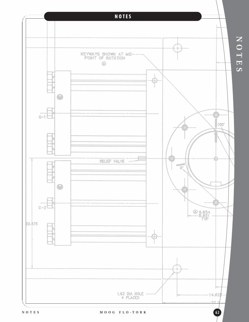
NOTES
M O O G F L O - T O R KN O T E S 63
N O T E S

1701 NORTH MAIN STREET
P.O. BOX 68ORRVILLE, OHIO 44667-0068
TEL 330 682 0010FAX 330 683 6857
WWW.MOOGFLO-TORK.COM
A W O R L D O F P O S S I B I L I T I E S
Y O U R L O C A L M O O G F L O - T O R K R E P R E S E N T A T I V E
ACT-125-2008