Embed Size (px)
Citation preview

Quick Start Guide00825-0200-4088, Rev BA
November 2014
Rosemount 4088B MultiVariable™ Transmitter with BSAP/MVS Protocols

November 2014Quick Start Guide
Procedures and instructions in this section may require special precautions to ensure the safety of the personnel performing the operation. Information that raises potential safety issues is indicated with a warning symbol ( ). Refer to the following safety messages before performing an operation preceded by this symbol.
NOTICEThis installation guide provides basic guidelines for the Rosemount 4088 MultiVariable Transmitter (reference manual document number 00809-0100-4088). It does not provide instructions for diagnostics, maintenance, service, or troubleshooting. Refer to the 4088 MultiVariable Transmitter Reference Manual for more instruction. All documents are available electronically at www.emersonprocess.com/rosemount.
Explosions could result in death or serious injury.
Installation of this transmitter in an explosive environment must be in accordance with the appropriate local, national, and international standards, codes, and practices. Review the approvals section of the 4088 MultiVariable Transmitter Reference Manual (00809-0100-4088) for any restrictions associated with a safe installation. Before connecting any instruments in an explosive atmosphere, ensure any instruments in the
loop are installed in accordance with intrinsically safe or non-incendive field wiring practices. In an Explosion-proof/Flameproof installation, do not remove the transmitter covers when
power is applied to the unit.
Process leaks may cause harm or result in death. Install and tighten process connectors before applying pressure.
Electrical shock can result in death or serious injury. Avoid contact with the leads and terminals. High voltage that may be present on leads can
cause electrical shock.
Conduit/cable entries Unless marked, the conduit/cable entries in the transmitter housing use a 1/2-14 NPT thread
form. Entries marked "M20" are M20 x 1.5 thread form. On devices with multiple conduit entries, all entries will have the same thread form. Only use plugs, adapters, glands, or conduit with a compatible thread form when closing these entries.
When installing in a hazardous location, use only appropriately listed or Ex certified plugs, adapters, or glands in cable/conduit entries.
Contents Steps required for quick installation page 3Mount the transmitter . . . . . . . . . . page 4Consider housing rotation . . . . . . . page 8Set the switches . . . . . . . . . . . . . . . . page 9
Wiring and power up . . . . . . . . . . . .page 9Verify device configuration . . . . . page 15Trim the transmitter . . . . . . . . . . . page 16Product Certifications . . . . . . . . . . page 17
2

Quick Start GuideNovember 2014
Steps required for quick installation
Start >
Mount the transmitter
Consider housing rotation
Set the switches
Wiring and power up
Verify device configuration
Trim the transmitter
> Finish
3
November 2014Quick Start Guide
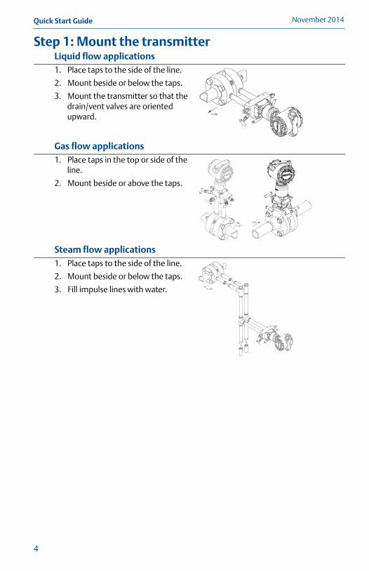
Step 1: Mount the transmitter Liquid flow applications1. Place taps to the side of the line.
2. Mount beside or below the taps.
3. Mount the transmitter so that the drain/vent valves are oriented upward.
Gas flow applications1. Place taps in the top or side of the
line.
2. Mount beside or above the taps.
Steam flow applications1. Place taps to the side of the line.
2. Mount beside or below the taps.
3. Fill impulse lines with water.
4
Quick Start GuideNovember 2014
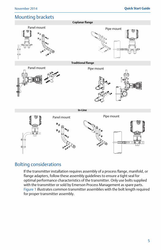
Mounting brackets
Bolting considerationsIf the transmitter installation requires assembly of a process flange, manifold, or flange adapters, follow these assembly guidelines to ensure a tight seal for optimal performance characteristics of the transmitter. Only use bolts supplied with the transmitter or sold by Emerson Process Management as spare parts. Figure 1 illustrates common transmitter assemblies with the bolt length required for proper transmitter assembly.
Coplanar flange
Traditional flange
In-Line
Panel mount Pipe mount
Panel mount Pipe mount
Panel mount Pipe mount
5

November 2014Quick Start Guide
Figure 1. Common Transmitter Assemblies
A. Transmitter with coplanar flangeB. Transmitter with coplanar flange and optional flange adaptersC. Transmitter with traditional flange and optional flange adaptersD. Transmitter with coplanar flange and optional Rosemount Conventional Manifold and
flange adapters
NoteFor all other manifolds, contact Rosemount Customer Central technical support or the local Emerson Process Management representative.
Bolts are typically carbon steel or stainless steel. Confirm the material by viewing the markings on the head of the bolt and referencing Figure 2. If bolt material is not shown in Figure 2, contact the local Emerson Process Management representative for more information.
Use the following bolt installation procedure:1. Carbon steel bolts do not require lubrication and the stainless steel bolts are
coated with a lubricant to ease installation. However, no additional lubricant should be applied when installing either type of bolt.
2. Finger-tighten the bolts.
3. Torque the bolts to the initial torque value using a crossing pattern. See Figure 2 for initial torque value.
4. Torque the bolts to the final torque value using the same crossing pattern. See Figure 2 for final torque value.
5. Verify the flange bolts are protruding through the sensor module before applying pressure (see Figure 3).
4 x 1.75-in. (44 mm)4 x 2.88-in. (73 mm)
A B
C
4 x 1.75-in. (44 mm)
D
4 x 1.50-in. (38 mm)
4 x 2.25-in. (57 mm)
4 x 1.75-in. (44 mm)
6
Quick Start GuideNovember 2014
7
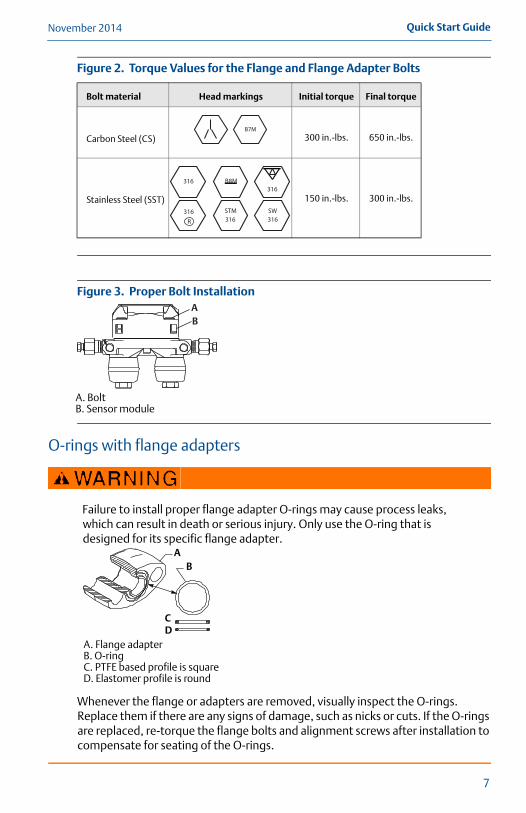
Figure 2. Torque Values for the Flange and Flange Adapter Bolts
Figure 3. Proper Bolt Installation
A. BoltB. Sensor module
O-rings with flange adapters
Whenever the flange or adapters are removed, visually inspect the O-rings. Replace them if there are any signs of damage, such as nicks or cuts. If the O-rings are replaced, re-torque the flange bolts and alignment screws after installation to compensate for seating of the O-rings.
Bolt material Head markings Initial torque Final torque
Carbon Steel (CS) 300 in.-lbs. 650 in.-lbs.
Stainless Steel (SST) 150 in.-lbs. 300 in.-lbs.
Failure to install proper flange adapter O-rings may cause process leaks, which can result in death or serious injury. Only use the O-ring that is designed for its specific flange adapter.
A. Flange adapterB. O-ringC. PTFE based profile is squareD. Elastomer profile is round
B7M
316316
316SW
316STM316
R
B8M
AB
AB
CD
November 2014Quick Start Guide
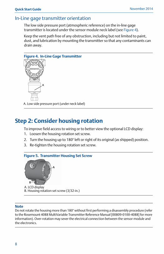
In-Line gage transmitter orientationThe low side pressure port (atmospheric reference) on the in-line gage transmitter is located under the sensor module neck label (see Figure 4).
Keep the vent path free of any obstruction, including but not limited to paint, dust, and lubrication by mounting the transmitter so that any contaminants can drain away.
Figure 4. In-Line Gage Transmitter
A. Low side pressure port (under neck label)
Step 2: Consider housing rotationTo improve field access to wiring or to better view the optional LCD display:1. Loosen the housing rotation set screw.
2. Turn the housing up to 180° left or right of its original (as shipped) position. 3. Re-tighten the housing rotation set screw.
Figure 5. Transmitter Housing Set Screw
A. LCD displayB. Housing rotation set screw (3/32-in.)
NoteDo not rotate the housing more than 180° without first performing a disassembly procedure (refer to the Rosemount 4088 MultiVariable Transmitter Reference Manual [00809-0100-4088] for more information). Over-rotation may sever the electrical connection between the sensor module and the electronics.
A
A
B
8

Quick Start GuideNovember 2014
Step 3: Set the switchesThe transmitter’s default configuration for the AC Termination is in the off position. The transmitter’s default configuration for the security switch is in the off position. 1. If the transmitter is installed, secure the bus and remove power.
2. Remove the housing cover opposite the field terminals side. Do not remove the housing cover in explosive environments.
3. Slide the security and AC Termination switches into the preferred position by using a small screwdriver. Note that the security switch will need to be in the off position in order to make any configuration changes.
4. Reinstall the housing cover and tighten so that the cover is fully seated with metal to metal contact between the housing and cover in order to meet explosion proof requirements.
Figure 6. Transmitter Switch Configuration
A. SecurityB. AC termination
Step 4: Wiring and power up Use the following steps to wire the transmitter:1. Remove the cover on the field terminals side of the housing.
2. Set up based on optional process temperature input.a. If the optional process temperature input is being utilized, follow the
procedure “Install optional process temperature input (PT 100 RTD sensor)” on page 14.
b. If there will not be an optional temperature input, plug and seal the unused conduit connection.
3. Connect the positive lead from the power source to the “PWR +” terminal, and the negative lead to the “PWR –” terminal.
4. Connect the transmitter to the RS-485 bus as shown in Figure 7.a. Connect the A lead to the “A” terminal.b. Connect the B lead to the “B” terminal.
NoteThe Rosemount 4088 MultiVariable Transmitter uses RS-485 Modbus® with 8 data bits, one stop bit and no parity. The default baud rate is 9600.
AB
9
November 2014Quick Start Guide
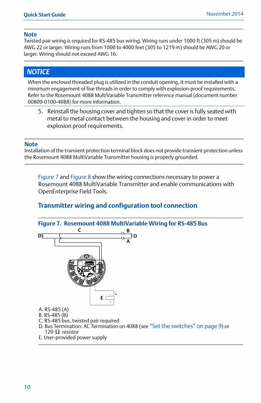
NoteTwisted pair wiring is required for RS-485 bus wiring. Wiring runs under 1000 ft (305 m) should be AWG 22 or larger. Wiring runs from 1000 to 4000 feet (305 to 1219 m) should be AWG 20 or larger. Wiring should not exceed AWG 16.
5. Reinstall the housing cover and tighten so that the cover is fully seated with metal to metal contact between the housing and cover in order to meet explosion proof requirements.
Figure 7 and Figure 8 show the wiring connections necessary to power a Rosemount 4088 MultiVariable Transmitter and enable communications with OpenEnterprise Field Tools.
Transmitter wiring and configuration tool connection
Figure 7. Rosemount 4088 MultiVariable Wiring for RS-485 Bus
A. RS-485 (A)B. RS-485 (B)C. RS-485 bus, twisted pair requiredD. Bus Termination: AC Termination on 4088 (see “Set the switches” on page 9) or
120 resistorE. User-provided power supply
NOTICEWhen the enclosed threaded plug is utilized in the conduit opening, it must be installed with a minimum engagement of five threads in order to comply with explosion-proof requirements. Refer to the Rosemount 4088 MultiVariable Transmitter reference manual (document number 00809-0100-4088) for more information.
NoteInstallation of the transient protection terminal block does not provide transient protection unless the Rosemount 4088 MultiVariable Transmitter housing is properly grounded.
D DB
A
C
E
Ω
10

Quick Start GuideNovember 2014
It is not required to remove the Rosemount 4088 from the RS-485 network when configuring over the local HART port. The device should be taken out of service or put in manual prior to performing any configuration changes.
NoteCertain BSAP parameters (such as MANUAL.LOCK.CFG or EXECUTE.CALIB) are accessible only through BSAP and must be configured using the TechView component of OpenEnterprise Field Tools.
Figure 8. Rosemount 4088 MultiVariable Configuration via HART® or BSAP (local) Port
NoteIn the TechView component of OpenEnterprise Field Tools, specify a baud rate of 1200 baud, and specify the transmitter’s local address. For more information on 4088B configuration/calibration tasks in TechView, see the TechView User’s Guide (part D301430X012).
A. TechView (BSAP protocol) component of OpenEnterprise Field Tools
B. MACTek® Viator® USB HART Interface C. User-provided power supply
A B
C
11
November 2014Quick Start Guide
12
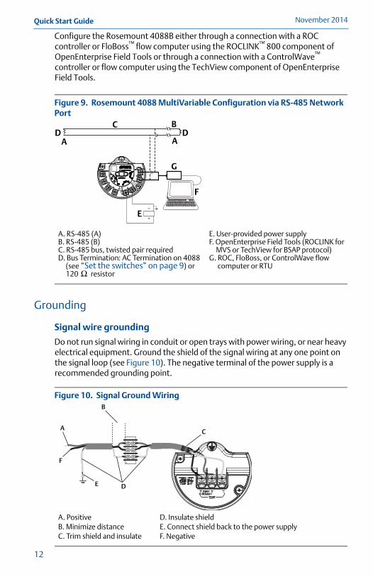
Configure the Rosemount 4088B either through a connection with a ROC controller or FloBoss™ flow computer using the ROCLINK™ 800 component of OpenEnterprise Field Tools or through a connection with a ControlWave™ controller or flow computer using the TechView component of OpenEnterprise Field Tools.
Figure 9. Rosemount 4088 MultiVariable Configuration via RS-485 Network Port
Grounding
Signal wire grounding
Do not run signal wiring in conduit or open trays with power wiring, or near heavy electrical equipment. Ground the shield of the signal wiring at any one point on the signal loop (see Figure 10). The negative terminal of the power supply is a recommended grounding point.
Figure 10. Signal Ground Wiring
A. RS-485 (A)B. RS-485 (B)C. RS-485 bus, twisted pair requiredD. Bus Termination: AC Termination on 4088
(see “Set the switches” on page 9) or 120 resistor
E. User-provided power supplyF. OpenEnterprise Field Tools (ROCLINK for
MVS or TechView for BSAP protocol)G. ROC, FloBoss, or ControlWave flow
computer or RTU
A. PositiveB. Minimize distanceC. Trim shield and insulate
D. Insulate shieldE. Connect shield back to the power supplyF. Negative
AD
C B
AD
E
G
F
Ω
DP
A
D
F
B
C
E
Quick Start GuideNovember 2014
Transmitter case
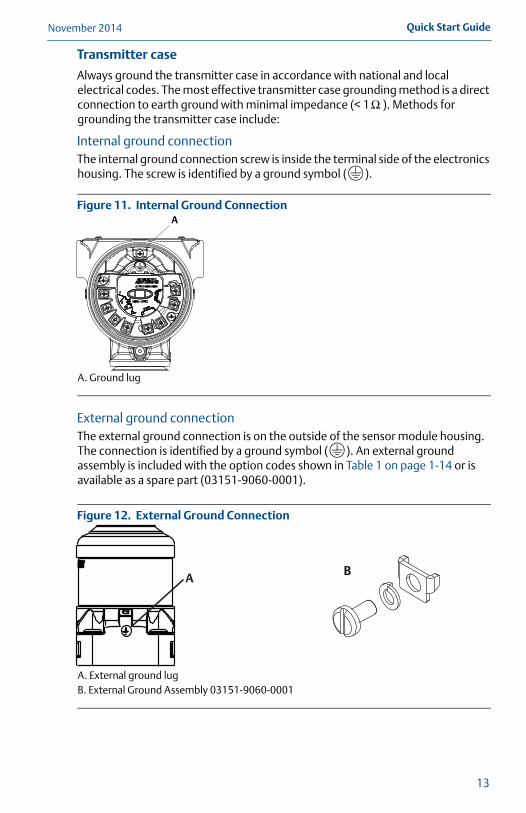
Always ground the transmitter case in accordance with national and local electrical codes. The most effective transmitter case grounding method is a direct connection to earth ground with minimal impedance (< 1 ). Methods for grounding the transmitter case include:
Internal ground connectionThe internal ground connection screw is inside the terminal side of the electronics housing. The screw is identified by a ground symbol ( ).
Figure 11. Internal Ground Connection
A. Ground lug
External ground connectionThe external ground connection is on the outside of the sensor module housing. The connection is identified by a ground symbol ( ). An external ground assembly is included with the option codes shown in Table 1 on page 1-14 or is available as a spare part (03151-9060-0001).
Figure 12. External Ground Connection
A. External ground lugB. External Ground Assembly 03151-9060-0001
Ω
A
AB
13
November 2014Quick Start Guide
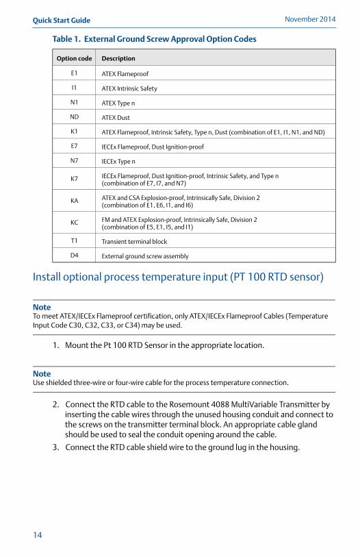
Table 1. External Ground Screw Approval Option Codes
Install optional process temperature input (PT 100 RTD sensor)
NoteTo meet ATEX/IECEx Flameproof certification, only ATEX/IECEx Flameproof Cables (Temperature Input Code C30, C32, C33, or C34) may be used.
1. Mount the Pt 100 RTD Sensor in the appropriate location.
NoteUse shielded three-wire or four-wire cable for the process temperature connection.
2. Connect the RTD cable to the Rosemount 4088 MultiVariable Transmitter by inserting the cable wires through the unused housing conduit and connect to the screws on the transmitter terminal block. An appropriate cable gland should be used to seal the conduit opening around the cable.
3. Connect the RTD cable shield wire to the ground lug in the housing.
Option code Description
E1 ATEX Flameproof
I1 ATEX Intrinsic Safety
N1 ATEX Type n
ND ATEX Dust
K1 ATEX Flameproof, Intrinsic Safety, Type n, Dust (combination of E1, I1, N1, and ND)
E7 IECEx Flameproof, Dust Ignition-proof
N7 IECEx Type n
K7 IECEx Flameproof, Dust Ignition-proof, Intrinsic Safety, and Type n (combination of E7, I7, and N7)
KA ATEX and CSA Explosion-proof, Intrinsically Safe, Division 2 (combination of E1, E6, I1, and I6)
KC FM and ATEX Explosion-proof, Intrinsically Safe, Division 2 (combination of E5, E1, I5, and I1)
T1 Transient terminal block
D4 External ground screw assembly
14
Quick Start GuideNovember 2014
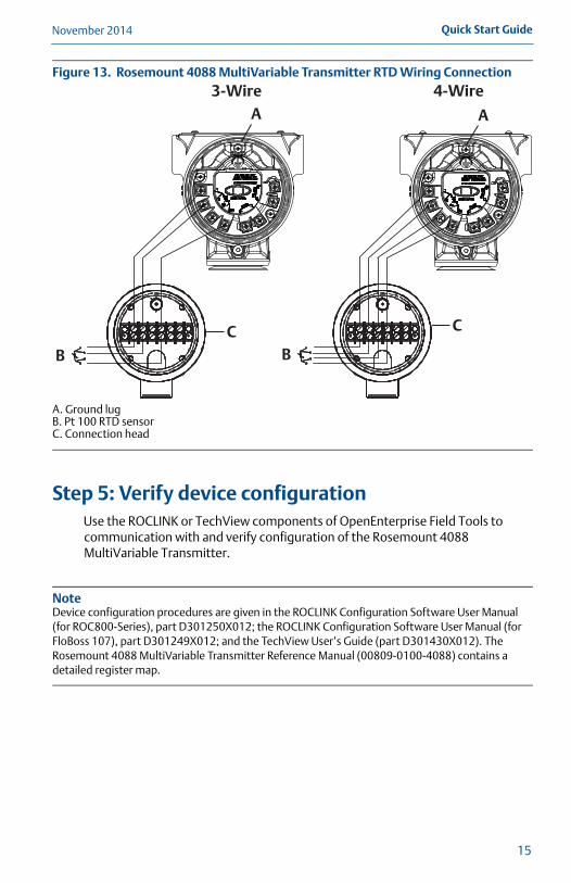
Figure 13. Rosemount 4088 MultiVariable Transmitter RTD Wiring Connection
A. Ground lugB. Pt 100 RTD sensorC. Connection head
Step 5: Verify device configurationUse the ROCLINK or TechView components of OpenEnterprise Field Tools to communication with and verify configuration of the Rosemount 4088 MultiVariable Transmitter.
NoteDevice configuration procedures are given in the ROCLINK Configuration Software User Manual (for ROC800-Series), part D301250X012; the ROCLINK Configuration Software User Manual (for FloBoss 107), part D301249X012; and the TechView User’s Guide (part D301430X012). The Rosemount 4088 MultiVariable Transmitter Reference Manual (00809-0100-4088) contains a detailed register map.
3-Wire 4-Wire
A
B B
A
CC
15

November 2014Quick Start Guide
Step 6: Trim the transmitterTransmitters are shipped fully calibrated per request or by the factory default of full scale.
Use the ROCLINK or TechView components of OpenEnterprise Field Tools to communicate with and perform maintenance on the Rosemount 4088 MultiVariable Transmitter.
Zero trim A zero trim is a single-point adjustment used for compensating mounting position and line pressure effects on static and differential pressure sensors. When performing a zero trim, ensure that the equalizing valve is open and all wet legs are filled to the correct level.
The transmitter will allow up to 95% of URL zero error to be trimmed through a lower SP trim procedure.
If zero offset is less than 5% of URL, follow the user interface software instructions below.
Performing a zero trim using OpenEnterprise Field Tools
See the product-specific ROCLINK manual (ROCLINK Configuration Software User Manual [for ROC800-Series], part D301250X012, or the ROCLINK Configuration Software User Manual [for FloBoss 107], part D301249X012) or the TechView User’s Guide (part D301430X012) for information.
16

Quick Start GuideNovember 2014
Product Certifications
Ordinary Location Certification for FMAs standard, the transmitter has been examined and tested to determine that the design meets basic electrical, mechanical, and fire protection requirements by FM, a nationally recognized testing laboratory (NRTL) as accredited by the Federal Occupational Safety and Health Administration (OSHA).
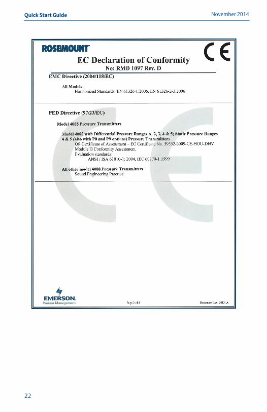
European Directive InformationA copy of the EC Declaration of Conformity can be found at the end of the Quick Start Guide. The most recent revision of the EC Declaration of Conformity can be found at www.emersonprocess.com/rosemount.
Hazardous Locations Certifications
North American Certifications
FM Approvals
E5 XP Class I, Division 1, Groups B, C, D (Ta = -50 °C to 85 °C); DIP Class II and Class III,Division 1, Groups E, F, G (Ta = -50 °C to 85 °C); Class I Zone 0/1 AEx d IIC T5 or T6 Ga/Gb (Ta = -50 °C to 80 °C); hazardous location; enclosure Type 4X/IP66/IP68; conduit seal not required
Special Conditions for Safe Use (X):1. The device contains a thin wall diaphragm. Installation, maintenance, and use
shall take into account the environmental conditions to which the diaphragm will be subjected. The manufacturers instruction for maintenance shall be followed in detail to assure safety during its expected lifetime.
2. In case of repair contact the manufacturer for information on the dimensions of the flameproof joint.
3. Appropriate cable, glands, and plugs need to be suitable for a temperature of 5 °C greater than maximum specified temperature for location where installed.
4. The applicable temperature class, ambient temperature range and process temperature range of the equipment is as follows:
T4 for -50 °C ≤ Ta ≤ 80 °C with T process = -50 °C to 120 °C T5 for -50 °C ≤ Ta ≤ 80 °C with T process = -50 °C to 80 °C T6 for -50 °C ≤ Ta ≤ 65 °C with T process = -50 °C to 65 °C
17

November 2014Quick Start Guide
18
I5 Intrinsic Safety Class I, Division 1, Groups C, D; Class II, Groups E, F, G; Class III; Class I Zone 0 AEx ia IIB T4; Nonincendive Class I, Div 2, Groups A, B, C, D; T4(-50 °C ≤ Ta ≤ 70 °C); when connected per Rosemount drawing 04088-1206; Type 4X
Special Conditions for Safe Use (X):1. The maximum permitted ambient temperature of the Model 4088 Pressure
Transmitter is 70 °C. To avoid the effects of process temperature and other thermal effects care shall be taken to ensure the surrounding ambient and the ambient inside the transmitter housing does not exceed 70 °C.
2. The enclosure may contain aluminum and is considered to present a potential risk of ignition by impact or friction. Care must be taken during installation and use to prevent impact or friction.
3. The Model 4088 Transmitters fitted with transient protection are not capable of withstanding the 500V test. This must be taken into account during installation.
Canadian Standards Association (CSA)
All CSA hazardous approved transmitters are dual seal certified per ANSI/ISA 12.27.01-2003.
E6 Explosion-proof for Class I, Division 1, Groups B, C, and D; Dust-Ignition-Proof for Class II and Class III, Division 1, Groups E, F, and G; suitable for Class I, Division 2, Groups A, B, C, and D, CSA Enclosure Type 4X; conduit seal not required.
I6 Intrinsically Safe for Class I, Division 1, Groups C and D, T3C, Class I, Zone 0, Ex ia IIb, T4; when connected per Rosemount drawing 04088-1207; enclosure Type 4X
European Certifications
ND ATEX DustCertificate No.: FM12ATEX0030X
II 2D Ex tb IIIC T95 °C Db (-20 °C Ta 85 °C)Vmax = 30VIP66
1180
Special Conditions for Safe Use (X):1. Cable entries must be used which maintain the ingress protection of the
enclosure to at least IP66.
2. Unused cable entries must be filled with suitable blanking plugs which maintain the ingress protection of the enclosure to at least IP66.
3. Cable entries and blanking plugs must be suitable for the ambient range of the apparatus and capable of withstanding a 7J impact test.

Quick Start GuideNovember 2014
E1 ATEX FlameproofCertificate No.: FM12ATEX0030XEx d IIC T5 or T6 Ga/GbT5 (-50 °C ≤ Tamb ≤ 80 °C)T6 (-50 °C ≤ Tamb ≤ 65 °C)Vmax = 30V
1180
Special Conditions for Safe Use (X):1. The device contains a thin wall diaphragm. Installation, maintenance, and use
shall take into account the environmental conditions to which the diaphragm will be subjected. The manufacturers instruction for maintenance shall be followed in detail to assure safety during its expected lifetime.
2. In case of repair contact the manufacturer for information on the dimensions of the flameproof joint.
3. Appropriate cable, glands, and plugs need to be suitable for a temperature of 5 °C greater than maximum specified temperature for location where installed.
4. The applicable temperature class, ambient temperature range and process temperature range of the equipment is as follows:
T4 for -50 °C ≤ Ta ≤ 80 °C with T process = -50 °C to 120 °C T5 for -50 °C ≤ Ta ≤ 80 °C with T process = -50 °C to 80 °C T6 for -50 °C ≤ Ta ≤ 65 °C with T process = -50 °C to 65 °C
E7 IECEx FlameproofCertificate No.: IECEx FMG 13.0024XEx d IIC T5 or T6 Ga/GbT5 (-50 °C ≤ Tamb ≤ 80 °C)T6 (-50 °C ≤ Tamb ≤ 65 °C)Vmax = 30V
Special Conditions for Safe Use (X):1. The device contains a thin wall diaphragm. Installation, maintenance, and use
shall take into account the environmental conditions to which the diaphragm will be subjected. The manufacturers instruction for maintenance shall be followed in detail to assure safety during its expected lifetime.
2. In case of repair contact the manufacturer for information on the dimensions of the flameproof joint.
3. Appropriate cable, glands, and plugs need to be suitable for a temperature of 5 °C greater than maximum specified temperature for location where installed.
4. The applicable temperature class, ambient temperature range and process temperature range of the equipment is as follows:
T4 for -50 °C ≤ Ta ≤ 80 °C with T process = -50 °C to 120 °C T5 for -50 °C ≤ Ta ≤ 80 °C with T process = -50 °C to 80 °C T6 for -50 °C ≤ Ta ≤ 65 °C with T process = -50 °C to 65 °C
19
November 2014Quick Start Guide
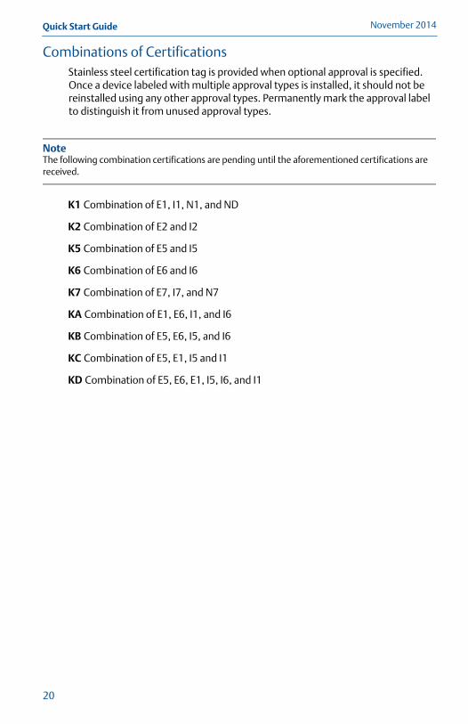
Combinations of CertificationsStainless steel certification tag is provided when optional approval is specified. Once a device labeled with multiple approval types is installed, it should not be reinstalled using any other approval types. Permanently mark the approval label to distinguish it from unused approval types.
NoteThe following combination certifications are pending until the aforementioned certifications are received.
K1 Combination of E1, I1, N1, and ND
K2 Combination of E2 and I2
K5 Combination of E5 and I5
K6 Combination of E6 and I6
K7 Combination of E7, I7, and N7
KA Combination of E1, E6, I1, and I6
KB Combination of E5, E6, I5, and I6
KC Combination of E5, E1, I5 and I1
KD Combination of E5, E6, E1, I5, I6, and I1
20

Quick Start GuideNovember 2014
21
November 2014Quick Start Guide
22

Quick Start GuideNovember 2014
23

November 2014Quick Start Guide
24

Quick Start GuideNovember 2014
25

?00825-0200-4088J?
Headquarters: Emerson Process ManagementRemote Automation Solutions6005 Rogerdale Road Houston, TX USA 77072T +1 (281) 879-2699 | F +1 (281) 988-4445www.EmersonProcess.com/Remote
Europe: Emerson Process ManagementRemote Automation SolutionsEmerson HouseUnit 8, Waterfront Business ParkDudley Road, Brierly HillDudley UK DY5 1LXT +44 1384 487200 | F +44 1384 487258www.EmersonProcess.com/Remote
North America/Latin America:Emerson Process ManagementRemote Automation Solutions6005 Rogerdale Road Houston, TX USA 77072T +1 (281) 879-2699 | F +1 (281) 988-4445www.EmersonProcess.com/Remote
Middle East/Africa:Emerson Process Management Remote Automation SolutionsEmerson FZEP.O. Box 17033Jebel Ali Free Zone - South 2Dubai U.A.E.T +971 4 8118100 | F +971 4 8865465www.EmersonProcess.com/Remote
© 2014 Rosemount Inc. All rights reserved. All marks property of owner. The Emerson logo is a trade mark and service mark of Emerson Electric Co.Rosemount and the Rosemount logotype are registered trademarks of Rosemount Inc. FloBoss, ROCLINK, TechView, ControlWave, and OpenEnterprise are trademarks of Remote Automation Solutions, a business unit of Emerson Process Management.Modbus is a registered trademark of the Modbus Organization, Inc.
Asia-Pacific:Emerson Process Management Remote Automation Solutions1 Pandan CrescentSingapore 128461T +65 6777 8211 | F +65 6777 0947www.EmersonProcess.com/Remote
Quick Start Guide00825-0200-4088, Rev BA
November 2014