Embed Size (px)
Citation preview

Quick Start Guide00825-0100-4803, Rev. CA
December 2012
4803_QIG_RevCA.fm Page 1 Monday, December 17, 2012 9:17 AM
Rosemount 3051S MultiVariable™ Transmitter
Rosemount 3051SF Series Flowmeter MultiVariable Transmitter
December 2012Quick Start Guide
4803_QIG_RevCA.fm Page 2 Monday, December 17, 2012 9:17 AM
v
NOTICEThis installation guide provides basic guidelines for the Rosemount 3051S MultiVariable transmitter (reference manual document number 00809-0100-4803). It also provides the basic 3051S MultiVariable transmitter configuration guidelines for the 3051SFA (reference manual document number 00809-0100-4809), 3051SFC (reference manual document number 00809-0100-4810), and 3051SFP (reference manual document number 00809-0100-4686). It does not provide instructions for diagnostics, maintenance, service, or troubleshooting. Refer to the 3051S MultiVariable transmitter reference manual for more instruction. All documents are available electronically at www.emersonprocess.com/rosemount.
Explosions could result in death or serious injury:
Installation of this transmitter in an explosive environment must be in accordance with the appropriate local, national, and international standards, codes, and practices. Please review the approvals section of the 3051S MultiVariable transmitter reference manual (00809-0100-4803) for any restrictions associated with a safe installation. Before connecting a Field communicator in an explosive atmosphere, ensure the instruments
in the loop are installed in accordance with intrinsically safe or non-incendive field wiring practices.
In an Explosion-proof/Flameproof installation, do not remove the transmitter covers when power is applied to the unit.
Process leaks may cause harm or result in death. Install and tighten process connectors before applying pressure. Electrical shock can result in death or serious injury. Avoid contact with the leads and terminals. High voltage that may be present on leads can
cause electrical shock.
Contents Mount the transmitter . . . . . . . page 3Consider housing rotation . . . . page 8Set the switches . . . . . . . . . . . . . page 9Connect wiring and power up page 10
Flow configuration . . . . . . . . . page 14Verify device configuration . . page 25Trim the transmitter . . . . . . . . page 28Product certifications . . . . . . . page 29
2

Quick Start GuideDecember 2012
4803_QIG_RevCA.fm Page 3 Monday, December 17, 2012 9:17 AM
Step 1: Mount the transmitter Liquid Flow Applications1. Place taps to the side of the line.
2. Mount beside or below the taps.
3. Mount the transmitter so that the drain/vent valves are oriented upward.
Gas Flow Applications1. Place taps in the top or side of the
line.
2. Mount beside or above the taps.
Steam Flow Applications1. Place taps to the side of the line.
2. Mount beside or below the taps.
3. Fill impulse lines with water.
3

December 2012Quick Start Guide
4803_QIG_RevCA.fm Page 4 Monday, December 17, 2012 9:17 AM
Mounting bracketsCoplanar™ Flange
Traditional Flange
Panel Mount
Panel Mount Pipe Mount
Pipe Mount
4

Quick Start GuideDecember 2012
4803_QIG_RevCA.fm Page 5 Monday, December 17, 2012 9:17 AM
Bolting considerationsIf the transmitter installation requires assembly of a process flange, manifold, or flange adaptors, follow these assembly guidelines to ensure a tight seal for optimal performance characteristics of the transmitter. Only use bolts supplied with the transmitter or sold by Emerson Process Management as spare parts. Figure 1 illustrates common transmitter assemblies with the bolt length required for proper transmitter assembly.
Figure 1. Common Transmitter Assemblies
Bolts are typically carbon steel or stainless steel. Confirm the material by viewing the markings on the head of the bolt and referencing Figure 3. If bolt material is not shown in Figure 3, contact the local Emerson Process Management representative for more information.
Use the following bolt installation procedure:1.Carbon steel bolts do not require lubrication and the stainless steel bolts are coated with a lubricant to ease installation. However, no additional lubricant should be applied when installing either type of bolt.
2.Finger-tighten the bolts.
3.Torque the bolts to the initial torque value using a crossing pattern.
See Figure 3 for initial torque value.
4.Torque the bolts to the final torque value using the same crossing pattern.
See Figure 3 for final torque value.
5.Verify that the flange bolts are protruding through the module isolator plate before applying pressure.
4 x 1.75-in. (44 mm)
4 x 2.88-in. (73 mm)
A. Transmitter with Coplanar Flange
B. Transmitter with Coplanar Flange and Optional Flange Adapters
C. Transmitter with Traditional Flange and Optional Flange Adapters
D. Transmitter with Coplanar Flange and Optional Manifold and Flange Adapters
4 x 1.75-in. (44 mm) 4 x
1.50-in. (38 mm) 4 x 1.75-in.
(44 mm)
4 x 2.25-in. (57 mm)
5

December 2012Quick Start Guide
4803_QIG_RevCA.fm Page 6 Monday, December 17, 2012 9:17 AM
Figure 2. Module Isolator Plate
Figure 3. Torque Values for the Flange and Flange Adapter Bolts
Bolt Material Head Markings Initial Torque Final Torque
Carbon Steel (CS)
300 in.-lbs. 650 in.-lbs.
Stainless Steel (SST)
150 in.-lbs. 300 in.-lbs.
Module Isolator PlateBolt
B7M
316316
316SW
316STM316
R
B8M
6

Quick Start GuideDecember 2012
4803_QIG_RevCA.fm Page 7 Monday, December 17, 2012 9:17 AM
O-rings with Flange Adaptors
Whenever the flange or adapters are removed, visually inspect the o-rings. Replace them if there are any signs of damage, such as nicks or cuts. If the o-rings are replaced, re-torque the flange bolts and alignment screws after installation to compensate for seating of the o-rings.
Failure to install proper flange adapter O-rings may cause process leaks, which can result in death or serious injury. The two flange adapters are distinguished by
unique O-ring grooves. Only use the O-ring that is designed for its specific flange adapter, as shown below.
Rosemount 3051S / 3051 / 2051 / 3095
Rosemount 1151
Flange
O-ring
Flange AdapterO-ring
PTFE BasedElastomer
PTFEElastomer
7

December 2012Quick Start Guide
4803_QIG_RevCA.fm Page 8 Monday, December 17, 2012 9:17 AM
Step 2: Consider housing rotationTo improve field access to wiring or to better view the optional LCD display:
Figure 4. Transmitter Housing Set Screw
1. Loosen the housing rotation set screw.
2. Turn the housing up to 180° left or right of its original (as shipped) position.
3. Retighten the housing rotation set screw.
NoteDo not rotate the housing more than 180° without first performing a disassembly procedure (see Section 4 of the 3051S MultiVariable transmitter reference manual (00809-0100-4803) for more information). Over-rotation may sever the electrical connection between the sensor module and the feature board electronics.
Housing Rotation Set Screw (3/32-in.)
FeatureBoard
8

Quick Start GuideDecember 2012
4803_QIG_RevCA.fm Page 9 Monday, December 17, 2012 9:17 AM
Step 3: Set the switchesThe transmitter’s default configuration sets the alarm condition to high (HI) and the security to off.1. If the transmitter is installed, secure the loop and remove power.
2. Remove the housing cover opposite the field terminals side. Do not remove the housing cover in explosive environments.
3. Slide the security and alarm switches into the preferred position by using a small screwdriver.
4. Reinstall the housing cover so that metal contacts metal to meet explosion-proof requirements.
Figure 5. Transmitter Switch Configuration
AlarmSecurity
9

December 2012Quick Start Guide
4803_QIG_RevCA.fm Page 10 Monday, December 17, 2012 9:17 AM
Step 4: Connect wiring and power up
NoteDo not connect the power across the test terminals. Power could damage the test diode in the test connection. Twisted pairs yield best results. Use 24 AWG to 14 AWG wire and do not exceed 5,000 feet (1500 meters).
Use the following steps to wire the transmitter:1. Remove the cover on the field terminals side of the housing.
2. Connect the positive lead to the “PWR/COMM +” terminal, and the negative lead to the “PWR/COMM –” terminal.
3. If the optional process temperature input is not installed, plug and seal the unused conduit connection. If the optional process temperature input is being utilized, see “Install optional process temperature input (Pt 100 RTD Sensor)” on page 13 for more information.
4. If applicable, install wiring with a drip loop. Arrange the drip loop so the bottom is lower than the conduit connections and the transmitter housing.
5. Reinstall the housing cover and tighten so that metal contacts metal to meet explosion-proof requirements.
NOTICEWhen the enclosed pipe plug is utilized in the conduit opening, it must be installed with a minimum engagement of five threads in order to comply with explosion-proof requirements. Refer to the 3051S MultiVariable transmitter reference manual (document number 00809-0100-4803) for more information.
10

Quick Start GuideDecember 2012
4803_QIG_RevCA.fm Page 11 Monday, December 17, 2012 9:17 AM
Figure 6 shows the wiring connections necessary to power a 3051S MultiVariable transmitter and enable communications with a hand-held Field Communicator.
Conduit electrical connector wiring (Option GE or GM)For 3051S MultiVariable transmitters with conduit electrical connectors GE or GM, refer to the cordset manufacturer’s installation instructions for wiring details. For FM Intrinsically Safe, Division 2 hazardous locations, install in accordance with Rosemount drawing 03151-1009 to maintain outdoor rating (NEMA 4X and IP66.) See Appendix B: Product Certifications of the 3051S MultiVariable transmitter reference manual (00809-0100-4803).
Figure 6. Transmitter Wiring3051SMV without Optional Process Temperature
Connection 3051SMV with Optional Process Temperature
Connection
NoteInstallation of the transient protection terminal block does not provide transient protection unless the 3051S MultiVariable transmitter housing is properly grounded.
RL 250
Power Supply
Power Supply
RL 250
11

December 2012Quick Start Guide
4803_QIG_RevCA.fm Page 12 Monday, December 17, 2012 9:17 AM
Power supplyThe dc power supply should provide power with less than two percent ripple. The total resistance load is the sum of the resistance of the signal leads and the load resistance of the controller, indicator, intrinsic safety barriers, and related components.
Figure 7. Load Limitation
3051S MultiVariable Transmitter
Maximum Loop Resistance = 43.5 x (Power Supply Voltage – 12.0)
HART communication requires a minimum loop resistance of 250.
Voltage (Vdc)
Load
(Oh
ms)
OperatingRegion
1322
1000
500
012.0 20 30
42.4
12

Quick Start GuideDecember 2012
4803_QIG_RevCA.fm Page 13 Monday, December 17, 2012 9:17 AM
Install optional process temperature input (Pt 100 RTD Sensor)
NoteTo meet ATEX/IECEx Flameproof certification, only ATEX/IECEx Flameproof Cables (Temperature Input Code C30, C32, C33, or C34) may be used.
1. Mount the Pt 100 RTD Sensor in the appropriate location.
NoteUse shielded four-wire cable for the process temperature connection.
2. Connect the RTD cable to the 3051S MultiVariable transmitter by inserting the cable wires through the unused housing conduit and connect to the four screws on the transmitter terminal block. An appropriate cable gland should be used to seal the conduit opening around the cable.
3. Connect the RTD cable shield wire to the ground lug in the housing.
Figure 8. 3051S MultiVariable Transmitter RTD Wiring Connection
RTD Cable Assembly Wires
Red
Wh
ite
Pt 100 RTDSensor
Ground Lug
13

December 2012Quick Start Guide
4803_QIG_RevCA.fm Page 14 Monday, December 17, 2012 9:17 AM
Step 5: Flow configuration
Engineering Assistant 6.1 or laterThe 3051SMV Engineering Assistant 6.1 or later is PC-based software that performs configuration, maintenance, diagnostic functions, and serves as the primary communication interface to the 3051S MultiVariable transmitter with the Fully Compensated Mass and Energy Flow Feature Board.
The 3051SMV Engineering Assistant software is required to complete the flow configuration.
System requirementsThe following are the minimum system requirements to install the 3051SMV Engineering Assistant software: Pentium-grade Processor: 500 MHz or faster Operating System: Windows XP Professional (32-bit), or Windows 7 (32-bit or
64-bit) 256 MB RAM 100 MB free hard disk space RS232 serial port or USB port (for use with HART modem) CD-ROM
Installing 3051SMV Engineering Assistant 6.1 or later1. Uninstall any existing versions of Engineering Assistant 6 currently installed on
the PC.
2. Insert the new Engineering Assistant disk into the CD-ROM.
3. Windows should detect the presence of a CD and start the installation program. Follow the on-screen prompts to finish the installation. If Windows does not detect the CD, use Windows Explorer or My Computer to view the contents of the CD-ROM, and then double click the SETUP.EXE program.
4. A series of screens (Installation Wizard) will appear and assist in the installation process. Follow the on-screen prompts. It is recommended to use the default installation settings.
NoteEngineering Assistant versions 6.1 or later require the use of Microsoft® .NET Framework version 4.0 or later. If .NET version 4.0 is not currently installed, the software will be automatically installed during the Engineering Assistant installation. Microsoft .NET version 4.0 requires an additional 200 MB of disk space.
14

Quick Start GuideDecember 2012
4803_QIG_RevCA.fm Page 15 Monday, December 17, 2012 9:17 AM
Connecting to a personal computerFigure 9 shows how to connect a computer to a 3051S MultiVariable transmitter.
Figure 9. Connecting a PC to the 3051S MultiVariable Transmitter
1. Remove the cover from the field terminals side of the housing.
2. Power the device as outlined in “Step 4: Connect Wiring and Power Up.”
3. Connect the HART modem cable to the PC.
4. On the side of the transmitter marked “Field Terminals,” connect the modem mini-grabbers to the two terminals marked “PWR/COMM.”
5. Launch the 3051SMV Engineering Assistant software. For more information on launching software, see “Launching Engineering Assistant 6.1 or later” on page 18.
6. Once the configuration is complete, replace cover and tighten until metal contacts metal to meet explosion-proof requirements.
3051SMV without Optional Process Temperature Connection
3051SMV with Optional Process Temperature Connection
RL 250
Power Supply
Modem
Power Supply
RL 250
Modem
15

December 2012Quick Start Guide
4803_QIG_RevCA.fm Page 16 Monday, December 17, 2012 9:17 AM
Flow configurationThe 3051SMV Engineering Assistant is designed to guide the user through the setup of the flow configuration for a 3051S MultiVariable transmitter. The flow configuration screens allow the user to specify the fluid, operating conditions, and information about the primary element, including inside pipe diameter. This information will be used by the 3051SMV Engineering Assistant software to create flow configuration parameters that will be sent to the transmitter or saved for future use.
Online and offline modes
The Engineering Assistant software can be used in two modes: Online and Offline. In Online mode, the user can receive the configuration from the transmitter, edit the configuration, send the changed configuration to the transmitter, or save the configuration to a file. In Offline mode, the user can create a new flow configuration and save the configuration to a file or open and modify an existing file.
The following pages provide instructions on creating a new flow configuration in Offline Mode. For more information on other functionality, see the 3051S MultiVariable transmitter reference manual (00809-0100-4803).
Basic navigation overview
Figure 10. Engineering Assistant Basic Navigation Overview
16

Quick Start GuideDecember 2012
4803_QIG_RevCA.fm Page 17 Monday, December 17, 2012 9:17 AM
The Engineering Assistant software can be navigated in a variety of ways. The numbers below correspond to the numbers shown in Figure 10.1. The navigation tabs contain the flow configuration information. In Offline
mode, each tab will not become active until the required fields on the previous tab are completed. In Online mode, these tabs will be functional at all times.
2. The Reset button will return each field within all of the flow configuration tabs (Fluid Selection, Fluid Properties, and Primary Element Selection) to the values initially displayed at the start of the configuration.
a. In Online Mode, the values will return to the initial values received from the device before the start of the configuration.
b. If editing a previously saved flow configuration, the values will return to those that were last saved. If starting a new flow configuration, all entered values will be erased.
3. The Back button is used to step backward through the flow configuration tabs.
4. The Next button is used to step forward through the flow configuration tabs. In Offline mode, the Next button will not become active until all required fields on the current page are completed.
5. The Help button can be clicked at any time to get a detailed explanation of the information that is required on the current configuration tab.
6. Any configuration information that needs to be entered or reviewed will appear in this portion of the screen.
7. These menus navigate to the Configure Flow, Basic Setup, Device, Variables, Calibration, and Save/Send Configuration tabs.
8. These buttons navigate to Config/Setup, Device Diagnostics or Process Variables sections.
17

December 2012Quick Start Guide
4803_QIG_RevCA.fm Page 18 Monday, December 17, 2012 9:17 AM
Launching Engineering Assistant 6.1 or laterFlow configuration for the 3051S MultiVariable transmitter is achieved by launching the Engineering Assistant software from the START Menu. 1. Select the Start menu > All Programs > Engineering Assistant. Engineering
Assistant will open to the screen shown in Figure 11.
2. Click the Offline button located in the lower right hand corner of the screen shown in Figure 11.
Figure 11. Engineering Assistant Device Connection screen
18

Quick Start GuideDecember 2012
4803_QIG_RevCA.fm Page 19 Monday, December 17, 2012 9:17 AM
PreferencesThe Preferences tab, shown in Figure 12, allows the user to select the preferred engineering units to display.1. Select the preferred engineering units.
2. If Custom Units are selected, configure the Individual Parameters.
3. Check the box if unit preferences should be retained for future Engineering Assistant sessions.
Figure 12. Preferences Tab
19

December 2012Quick Start Guide
4803_QIG_RevCA.fm Page 20 Monday, December 17, 2012 9:17 AM
Fluid selection for database liquid/gasThe Fluid Selection tab shown in Figure 13 allows the user to choose the process fluid.
Figure 13. Fluid Selection Tab
NoteThe following example will show a flow configuration for the Database Gas Air used with a 405C Conditioning Orifice Plate as the primary element. The procedure to set up any other fluid with any other primary element will be similar to this example. Natural gases, custom liquids, and custom gases require additional steps during the configuration. See Section 3 of the 3051S MultiVariable transmitter reference manual (00809-0100-4803) for more information.
1. Engineering Assistant may open to the Preferences tab. Using the tabs at the top of the screen, navigate to the Fluid Selection tab.
2. Expand the Gas category (click on the + icon).
3. Expand the Database Gas category.
4. Select Air from the list of database fluids.
5. Enter the Nominal Operating Pressure, press the Enter or Tab key.
6. Enter the Nominal Operating Temperature, press the Enter or Tab key. Engineering Assistant will automatically fill in suggested operating ranges, as shown in Figure 13. These values may be edited as needed by the user.
7. Verify that the Reference / Atmospheric Conditions are correct for the application. These values may be edited as needed.
20

Quick Start GuideDecember 2012
4803_QIG_RevCA.fm Page 21 Monday, December 17, 2012 9:17 AM
NoteReference pressure and temperature values are used by Engineering Assistant to convert the flow rate from mass units to mass units expressed as standard or normal volumetric units.
8. Click Next > to proceed to the Fluid Properties tab.
Fluid properties
NoteThe Fluid Properties tab is an optional step and is not required to complete a flow configuration.
The Fluid Properties tab for the database gas air is shown in Figure 14. The user may verify that the properties of the chosen fluid are acceptable. 1. To check density, compressibility, and viscosity of the selected fluid at other
pressure and temperature values, enter a Pressure and Temperature and click Calculate.
NoteChanging the pressure and temperature values on the Fluid Properties tab does not affect the fluid configuration.
Figure 14. Fluid Properties Tab
21

December 2012Quick Start Guide
4803_QIG_RevCA.fm Page 22 Monday, December 17, 2012 9:17 AM
Primary element selectionThe Primary Element Selection tab shown in Figure 15 allows the user to choose the primary element.
Figure 15. Primary Element Selection Tab
Continuing with the example configuration:1. Expand the Conditioning Orifice Plate category.
2. Select 405C/3051SFC.
3. Enter the Measured Meter Tube Diameter (pipe ID) at a Reference Temperature. If the meter tube diameter cannot be measured, select a Nominal Pipe Size and Pipe Schedule to input an estimated value for the meter tube diameter (English units only).
4. If necessary, edit the Meter Tube Material.
5. Enter the Line Size and select the Beta of the Conditioning Orifice Plate. The required primary element sizing parameters will be different depending on what primary element was selected.
6. If necessary, select a Primary Element Material from the drop-down menu.
7. Click Next > to advance to the Save / Send Configuration tab.
NoteTo be in compliance with appropriate national or international standards, beta ratios and differential producer diameters should be within the limits as listed in the applicable standards. The Engineering Assistant software will alert the user if a primary element value exceeds these limits, but will allow the user to proceed with the flow configuration.
22

Quick Start GuideDecember 2012
4803_QIG_RevCA.fm Page 23 Monday, December 17, 2012 9:17 AM
Save / send configurationThe Save / Send Configuration tab shown in Figure 16 allows the user to verify, save, and send the configuration information to the 3051S MultiVariable transmitter with the Fully Compensated Mass and Energy Flow Feature Board. 1. Review the information under the Flow Configuration heading and Device
Configuration heading.
NoteFor more information on device configuration, see “Step 6: Verify Device Configuration.”
Figure 16. Save / Send Configuration Tab
2. Click on the icon above each window to edit the configuration information in these windows. When all information is correct, move to step 3.
NoteThe user will be notified if the configuration has been modified since it was last sent to the transmitter. A warning message will be shown to the right of the Send Flow Data and/or Send Transmitter Data check boxes.
3. To send the configuration, click the Send To button.
NoteThe Send Flow Data and Send Transmitter Data check boxes can be used to select what configuration data is sent to the transmitter. If either check box is unselected, the corresponding data will not be sent.
23

December 2012Quick Start Guide
4803_QIG_RevCA.fm Page 24 Monday, December 17, 2012 9:17 AM
4. The Engineering Assistant Device Connection screen will appear, see Figure 17.
Figure 17. Engineering Assistant Device Connection Screen
5. Click the Search button located in the lower right hand corner of the screen. Engineering Assistant will begin to search for connected devices.
6. When the search is completed, choose the device to communicate with and click Send Configuration.
7. Once the configuration is finished being sent to the device, the user will be notified by a pop-up dialog box.
NoteAfter the configuration is sent to the device, saving the configuration file is recommended. The user can choose the Save button on the Save/Send screen or choose Save from the program Menu.
8. If finished with the configuration process, the user may close Engineering Assistant.
24

Quick Start GuideDecember 2012
4803_QIG_RevCA.fm Page 25 Monday, December 17, 2012 9:17 AM
Step 6: Verify device configurationUse 3051SMV Engineering Assistant or any HART-compliant master to communicate with and verify configuration of the 3051S MultiVariable transmitter.
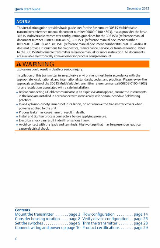
Table 1 shows the 375 Field Communicator fast keys for the Fully Compensated Mass and Energy Flow. Table 2 shows the fast keys for the Direct Process Variable Output.
NoteDevice configuration procedures are given for 3051SMV Engineering Assistant 6.1 or later and AMS Device Manager 9.0 or later in the 3051S MultiVariable transmitter reference manual (00809-0100-4803).
A check (�) indicates the basic configuration parameters. At a minimum, these parameters should be verified as part of the configuration and startup procedure.
Table 1. Fast Keys for Fully Compensated Mass and Energy Flow
Function Fast Key Sequence
Absolute Pressure Reading and Status 1,4,2,1,5
Absolute Pressure Sensor Limits 1,4,1,5,8
Absolute Pressure Units 1,3,3,5
Alarm and Saturation Level Configuration 1,4,2,6,6
Alarm and Saturation Levels 1,4,2,6
Analog Output Trim Options 1,2,5,2
Burst Mode Setup 1,4,3,3,3
Burst Mode Options 1,4,3,3,4
Callendar-van Dusen Sensor Matching 1,2,5,5,4
Configure Fixed Variables 1,2,4
� Damping 1,3,7
Diaphragm Seals Information 1,4,4,5
� Differential Pressure Low Flow Cutoff 1,4,1,1,6
Differential Pressure Reading and Status 1,4,2,1,4
Differential Pressure Sensor Trim Options 1,2,5,3
� Differential Pressure Zero Trim 1,2,5,3,1
Continued on Next Page
25

December 2012Quick Start Guide
4803_QIG_RevCA.fm Page 26 Monday, December 17, 2012 9:17 AM
Differential Pressure Units 1,3,3,4
Energy Rate Units 1,3,3,2
Energy Reading and Status 1,4,2,1,2
Equipped Sensors 1,4,4,4
Field Device Information 1,4,4,1
Flow Calculation Type 1,4,1,1,2
� Flow Rate Units 1,3,3,1
Flow Reading and Status 1,4,2,1,1
Gage Pressure Reading and Status 1,4,2,1,6
Gage Pressure Sensor Limits 1,4,1,5,9
Gage Pressure Units 1,3,3,6
LCD Configuration 1,3,8
Loop Test 1,2,2
Module Temperature Reading and Status 1,4,2,1,8
Module Temperature Units 1,3,3,8
Poll Address 1,4,3,3,1
Process Temperature Reading and Status 1,4,2,1,7
� Process Temperature Sensor Mode 1,4,1,6,8
Process Temperature Sensor Trim Options 1,2,5,5
Process Temperature Unit 1,3,3,7
� Ranging the Analog Output 1,2,5,1
Recall Factory Trim Settings 1,2,5,2,3
Sensor Information 1,4,4,2
Static Pressure Sensor Lower Trim (AP Sensor) 1,2,5,4,2
Static Pressure Sensor Trim Options 1,2,5,4
Static Pressure Sensor Zero Trim (GP Sensor) 1,2,5,4,1
Status 1,2,1
� Tag 1,3,1
Test Flow Calculation 1,2,3
Totalizer Configuration 1,4,1,3
Totalizer Reading and Status 1,4,2,1,3
Totalizer Units 1,3,3,3
Variable Mapping 1,4,3,4
Write Protect 1,3,5,4
Table 1. Fast Keys for Fully Compensated Mass and Energy Flow
Function Fast Key Sequence
26
Quick Start GuideDecember 2012
4803_QIG_RevCA.fm Page 27 Monday, December 17, 2012 9:17 AM
27
Table 2. Fast Keys for Direct Process Variable Output
Function Fast Key Sequence
Absolute Pressure Reading and Status 1,4,2,1,2
Absolute Pressure Sensor Limits 1,4,1,2,8
Absolute Pressure Units 1,3,3,2
Alarm and Saturation Level Configuration 1,4,2,6,6
Alarm and Saturation Levels 1,4,2,6
Analog Output Trim Options 1,2,4,2
Burst Mode Setup 1,4,3,3,3
Burst Mode Options 1,4,3,3,4
Callendar-van Dusen Sensor Matching 1,2,4,5,4
� Damping 1,3,7
Diaphragm Seals Information 1,4,4,4
Differential Pressure Reading and Status 1,4,2,1,1
Differential Pressure Sensor Trim Options 1,2,4,3
� Differential Pressure Zero Trim 1,2,4,3,1
� Differential Pressure Units 1,3,3,1
Equipped Sensors 1,4,4,3
Field Device Information 1,4,4,1
Gage Pressure Reading and Status 1,4,2,1,3
Gage Pressure Sensor Limits 1,4,1,2,9
Gage Pressure Units 1,3,3,3
LCD Configuration 1,3,8
Loop Test 1,2,2
Module Temperature Reading and Status 1,4,2,1,5
Module Temperature Units 1,3,3,5
Poll Address 1,4,3,3,1
Process Temperature Reading and Status 1,4,2,1,4
Process Temperature Sensor Trim Options 1,2,4,5
Process Temperature Unit 1,3,3,4
� Ranging the Analog Output 1,2,4,1
Recall Factory Trim Settings 1,2,4,2,3
Sensor Information 1,4,4,2
Static Pressure Sensor Lower Trim (AP Sensor) 1,2,4,4,2
Static Pressure Sensor Trim Options 1,2,4,4
Static Pressure Sensor Zero Trim (GP Sensor) 1,2,4,4,1
Status 1,2,1
� Tag 1,3,1
� Transfer Function 1,3,6
Variable Mapping 1,4,3,4
Write Protect 1,3,5,4
December 2012Quick Start Guide
4803_QIG_RevCA.fm Page 28 Monday, December 17, 2012 9:17 AM
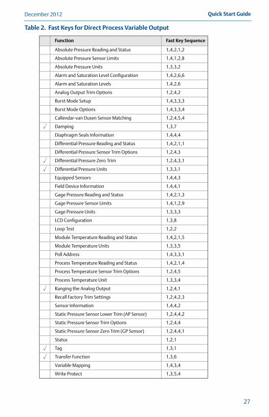
Step 7: Trim the transmitterTransmitters are shipped fully calibrated per request or by the factory default of full scale.
Zero trim A zero trim is a single-point adjustment used for compensating mounting position and line pressure effects on static and differential pressure sensors. When performing a zero trim, ensure that the equalizing valve is open and all wet legs are filled to the correct level.
The transmitter will only allow up to 5% of URL zero error to be trimmed.
Performing a zero trim using the 375 Field Communicator1. Equalize or vent the transmitter and connect the 375 (for more information on
connecting the 375, see Figure 6 on page 11).
2. If the device is equipped with a static pressure sensor, zero the sensor by inputting the following fast key sequence at the 3051S MultiVariable transmitter menu:
3. Use the zero trim (selection 1) for a transmitter equipped with a gage static pressure sensor or lower sensor trim (selection 2) for a transmitted equipped with an absolute static pressure sensor.
NoteWhen performing a lower sensor trim on an absolute pressure sensor, it is possible to degrade the performance of the sensor if inaccurate calibration equipment is used. Use a barometer that is at least three times as accurate as the absolute sensor of the 3051S MultiVariable transmitter.
4. Zero the differential pressure sensor by inputting the following fast key sequence at the 3051S MultiVariable transmitter menu:
Flow Fast Keys
Direct Output Fast Keys Description
1,2,5,4 1,2,4,4 Static Pressure Sensor Trim Options
Flow Fast Keys
Direct OutputFast Keys Description
1,2,5,3,1 1,2,4,3,1 Differential Pressure Sensor Zero Trim
28

Quick Start GuideDecember 2012
4803_QIG_RevCA.fm Page 29 Monday, December 17, 2012 9:17 AM
29
Product certifications
Approved Manufacturing LocationsRosemount Inc. — Chanhassen, Minnesota USAEmerson Process Management GmbH & Co. — Wessling, GermanyEmerson Process Management Asia Pacific Private Limited — SingaporeBeijing Rosemount Far East Instrument Co., LTD — Beijing, China
Ordinary Location Certification for FMAs standard, the transmitter has been examined and tested to determine that the design meets basic electrical, mechanical, and fire protection requirements by FM, a nationally recognized testing laboratory (NRTL) as accredited by the Federal Occupational Safety and Health Administration (OSHA).
European Directive Information
The EC declaration of conformity for all applicable European directives for this product can be found at www.emersonprocess.com/rosemount. A hard copy may be obtained by contacting an Emerson Process Management representative.
ATEX Directive (94/9/EC)Emerson Process Management complies with the ATEX Directive.
European Pressure Equipment Directive (PED) (97/23/EC)Models with Differential Pressure Ranges = 2 to 5 inclusive with Static Pressure = Range 4 only. P9 and P0 options also. All other Model 3051SMV Pressure Transmitters— Sound Engineering PracticeTransmitter Attachments: Diaphragm Seal - Process Flange - Manifold — Sound Engineering PracticePrimary Elements, Flowmeter— See appropriate Primary Element QIG
Electro Magnetic Compatibility (EMC) (2004/108/EC)
EN 61326-1:2006 and EN 61326-2-3:2006
Hazardous locations certifications
North American certifications
FM ApprovalsE5 Explosion-proof for Class I, Division 1, Groups B, C, and D; dust-ignition proof for Class II
and Class III, Division 1, Groups E, F, and G; hazardous locations; enclosure Type 4X, conduit seal not required.
I5 Intrinsically Safe for use in Class I, Division 1, Groups A, B, C, and D; Class II, Division 1, Groups E, F, and G; Class III, Division 1; Class I, Zone 0 AEx ia IIC when connected in accordance with Rosemount drawing 03151-1206; Non-incendive for Class I, Division 2, Groups A, B, C, and D Enclosure Type 4X For entity parameters see control drawing 03151-1206.

December 2012Quick Start Guide
4803_QIG_RevCA.fm Page 30 Monday, December 17, 2012 9:17 AM
Canadian Standards Association (CSA) All CSA hazardous approved transmitters are dual seal certified per ANSI/ISA 12.27.01-2003.
E6 Explosion-proof for Class I, Division 1, Groups B, C, and D; Dust-Ignition-Proof for Class II and Class III, Division 1, Groups E, F, and G; suitable for Class I, Division 2, Groups A, B, C, and D, CSA Enclosure Type 4X; conduit seal not required.
I6 Intrinsically Safe for Class I, Division 1, Groups A, B, C, and D when connected in accordance with Rosemount drawings 03151-1207; For entity parameters see control drawing 03151-1207.
European CertificationsI1 ATEX Intrinsic Safety
Certificate No.: 08ATEX0064X II 1GEx ia IIC T4 (Ta = -60 °C to 70 °C) -HART
1180
Special conditions for safe use (x)
The apparatus is not capable of withstanding the 500 V test as defined in Clause 6.3.12 of EN 60079-11. This must be considered during installation.N1 ATEX Type n
Certificate No.: Baseefa 08ATEX0065X II 3 GEx nA nL IIC T4 (Ta = -40 °C to 70 °C)Ui = 45 Vdc maxIP66
Special conditions for safe use (x)
The apparatus is not capable of withstanding the 500 V insulation test required by Clause 6.8.1 of EN 60079-15. This must be taken into account when installing the apparatus.ND ATEX Dust
Certificate No.: BAS01ATEX1303X II 1 DT105°C (-20 °C ≤ Tamb ≤ 85 °C)Vmax = 42.4 volts maxA = 24 mAIP66
1180
Special conditions for safe use (x)1. The user must ensure that the maximum rated voltage and current (42.4 volts,
22 milliampere, DC) are not exceeded. All connections to other apparatus or associated apparatus shall have control over this voltage and current equivalent to a category “ib” circuit according to EN 60079-11.
Input Parameters
Loop / Power Groups
Ui = 30 V HART
Ii = 300 mA HART
Pi = 1.0 W HART
Ci = 14.8 nF HART
Li = 0 HART
30

Quick Start GuideDecember 2012
4803_QIG_RevCA.fm Page 31 Monday, December 17, 2012 9:17 AM
2. Cable entries must be used which maintain the ingress protection of the enclosure to at least IP66.
3. Unused cable entries must be filled with suitable blanking plugs which maintain the ingress protection of the enclosure to at least IP66.
4. Cable entries and blanking plugs must be suitable for the ambient range of the apparatus and capable of withstanding a 7J impact test.
5. The 3051S-* must be securely screwed in place to maintain the ingress protection of the enclosure.
E1 ATEX Flameproof Certificate No.: KEMA 00ATEX2143X II 1/2 GEx d IIC T6 (-50 °C ≤ Tamb ≤ 65 °C)Ex d IIC T5 (-50 °C ≤ Tamb ≤ 80 °C)Vmax = 42.4 V
1180
Special conditions for safe use (x)1. Appropriate ex d blanking plugs, cable glands, and wiring needs to be suitable
for a temperature of 90 °C.
2. This device contains a thin wall diaphragm. Installation, maintenance, and use shall take into account the environmental conditions to which the diaphragm will be subjected. The manufacturer’s instructions for maintenance shall be followed in detail to assure safety during its expected lifetime.
3. The 3051SMV does not comply with the requirements of IEC 60079-1 Clause 5.2, Table 2 for all joints. Contact Emerson Process Management for information on the dimensions of flameproof joints.
Japanese Certifications E4 TIIS Flameproof
Consult factory for availabilityI4 TIIS Intrinsically Safe
Consult factory for availability
INMETRO certifications E2 INMETRO Flameproof
Certificate No.: NCC 12.1128 XEx d IIC T6/T5 Ga/GbT6 (-50 °C ≤ Tamb ≤ +65 °C)T5 (-50 °C ≤ Tamb ≤ +80 °C)
Special conditions for safe use (x) 1. For processes with temperatures above 135°C, the user must assess whether
the temperature class of the SuperModule is appropriate because in these appliances there is a risk of the SuperModule temperature being above the T5 temperature class, considering that this temperature is one function of the ventilation type used on the equipment.
2. The Ex d blanking elements, cable glands and wiring shall be suitable for a temperature of 90 °C.
31

December 2012Quick Start Guide
4803_QIG_RevCA.fm Page 32 Monday, December 17, 2012 9:17 AM
3. The 3051 transmitter contains a thin wall diaphragm. Installation, maintenance and use shall take into account the environmental conditions to which the diaphragm will be subjected. The manufacturer's instructions for maintenance shall be followed in detail to assure safety during its expected lifetime.
4. In case of repair, contact the manufacturer for information about the dimensions of the flameproof joints.
I2 INMETRO Intrinsic SafetyCertificate No: NCC 12.1158 XEx ia IIC T4 GaT4 (-60 °C ≤ Tamb ≤ +70 °C)
Special conditions for safe use (x)If the equipment is fitted with the optional 90V transient suppressor, it is incapable of withstanding the 500V isolation from earth test and this must be taken into account during installation.
China (NEPSI) CertificationsE3 China Flameproof
Ex d II B+H2T3~T5I3 China Intrinsic Safety
Ex ia IIC T3/T4
IECEx CertificationsI7 IECEx Intrinsic Safety
Certificate No.: IECExBAS08.0025XEx ia IIC T4 (Ta = -60 °C to 70 °C) -HARTIP66
Special conditions for safe use (x)
The 3051SMV HART 4-20mA is not capable of withstanding the 500 V test as defined in clause 6.3.12 of IEC 60079-11. This must be taken into account during installation. N7 IECEx Type n
Certificate No.: IECExBAS08.0026XEx nAnL IIC T4 (Ta = -40 °C to 70 °C)Ui = 45 Vdc MAXIP66
Special conditions for safe use (x)
The apparatus is not capable of withstanding the 500 V insulation test required by Clause 6.8.1 of IEC 60079-15.
Input Parameters
Loop / Power Groups
Ui = 30 V HART
Ii = 300 mA HART
Pi = 1.0 W HART
Ci = 14.8 nF HART
Li = 0 HART
32
Quick Start GuideDecember 2012
4803_QIG_RevCA.fm Page 33 Monday, December 17, 2012 9:17 AM
E7 IECEx FlameproofCertificate No.: IECExKEM08.0010XEx d IIC T6 (-50 °C ≤ Tamb ≤ 65 °C)Ex d IIC T5 (-50 °C ≤ Tamb ≤ 80 °C)Vmax = 42.4 V
Special conditions for safe use (x)1. Appropriate ex d blanking plugs, cable glands, and wiring needs to be suitable
for a temperature of 90 °C.
2. This device contains a thin wall diaphragm. Installation, maintenance, and use shall take into account the environmental conditions to which the diaphragm will be subjected. The manufacturer’s instructions for maintenance shall be followed in detail to assure safety during its expected lifetime.
3. The 3051SMV does not comply with the requirements of IEC 60079-1 Clause 5.2, Table 2 for all joints. Contact Emerson Process Management for information on the dimensions of flameproof joints.
Combinations of Certifications
Stainless steel certification tag is provided when optional approval is specified. Once a device labeled with multiple approval types is installed, it should not be reinstalled using any other approval types. Permanently mark the approval label to distinguish it from unused approval types.K1 Combination of E1, I1, N1, and NDK2 Combination of E2 and I2K4 Combination of E4 and I4K5 Combination of E5 and I5K6 Combination of E6 and I6K7 Combination of E7, I7, and N7KA Combination of E1, E6, I1, and I6KB Combination of E5, E6, I5, and I6KC Combination of E5, E1, I5 and I1KD Combination of E5, E6, E1, I5, I6, and I1
33

December 2012Quick Start Guide
4803_QIG_RevCA.fm Page 34 Monday, December 17, 2012 9:17 AM
34

Quick Start GuideDecember 2012
4803_QIG_RevCA.fm Page 35 Monday, December 17, 2012 9:17 AM
35

December 2012Quick Start Guide
4803_QIG_RevCA.fm Page 36 Monday, December 17, 2012 9:17 AM
36

Quick Start GuideDecember 2012
4803_QIG_RevCA.fm Page 37 Monday, December 17, 2012 9:17 AM
NOTES
37

¢00825-0100-4801J¤
4803_QIG_RevCA.fm Page 38 Monday, December 17, 2012 9:17 AM
Rosemount Inc. 8200 Market Boulevard Chanhassen, MN USA 55317T (US) (800) 999-9307T (Intnl) (952) 906-8888F (952) 906-8889
Emerson Process ManagementAsia Pacific Private Limited1 Pandan CrescentSingapore 128461T (65) 6777 8211F (65) 6777 0947/65 6777 0743
Emerson Process Management GmbH & Co. OHGArgelsrieder Feld 382234 Wessling GermanyT 49 (8153) 9390, F49 (8153) 939172
Beijing Rosemount Far East Instrument Co., LimitedNo. 6 North Street, Hepingli, Dong Cheng DistrictBeijing 100013, ChinaT (86) (10) 6428 2233F (86) (10) 6422 8586
© 2012 Rosemount Inc. All rights reserved. All marks property of owner. The Emerson logo is a trade mark and service mark of Emerson Electric CoRosemount and the Rosemount logotype are registered trademarks of Rosemount Inc.
Quick Start Guide00825-0100-4803, Rev. CA
December 2012