Embed Size (px)
Citation preview

KMC Room Sensors and ThermostatsKMC Controls manufactures a variety of pneumatic, analog electronic, and digital room sensors and thermostats. Some sense only temperature, while others also add humidity, motion, and/or CO2 sensing. This document covers general principles for mounting and maintenance of room (temperature, humidity, motion, and CO2) sensors.
KMC also sells other kinds of sensors (e.g., duct, air flow, smoke, carbon monoxide, pressure) that are not covered by this document.
For additional general information about sensors, see the following information on the KMC web site.• Sensor and Thermostat Selection Fundamentals White Paper• Sensor and Thermostat Selection Guide• How Hot Do You Feel? (Humidity Effects, Sensing, and Control)• (CO2) Demand Control Ventilation Benefits for Your Building White Paper
KMC Controls, 19476 Industrial Drive, New Paris, IN 46553 / 877-444-5622 / Fax: 574-831-5252 / www.kmccontrols.com
Room Sensor and ThermostatMounting and Maintenance Application Guide
ContentsKMC Room Sensors and Thermostats .............................................1Handling Precautions ..................................................................2Mounting for Optimal Temperature Sensing .....................................2Mounting for Optimal Motion Sensing ............................................3Mounting Height .........................................................................5Reducing Temperature Sensing Errors ............................................6Troubleshooting (Location) ...........................................................6Maintenance ..............................................................................7Important Notices .......................................................................8Support .....................................................................................8
2 AG150119D
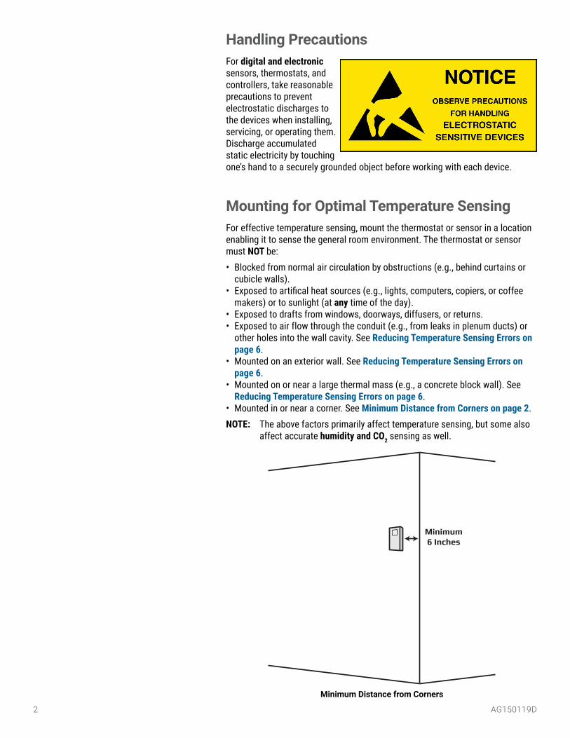
Minimum Distance from Corners
Handling PrecautionsFor digital and electronic sensors, thermostats, and controllers, take reasonable precautions to prevent electrostatic discharges to the devices when installing, servicing, or operating them. Discharge accumulated static electricity by touching one’s hand to a securely grounded object before working with each device.
Mounting for Optimal Temperature SensingFor effective temperature sensing, mount the thermostat or sensor in a location enabling it to sense the general room environment. The thermostat or sensor must NOT be:• Blocked from normal air circulation by obstructions (e.g., behind curtains or
cubicle walls).• Exposed to artifical heat sources (e.g., lights, computers, copiers, or coffee
makers) or to sunlight (at any time of the day).• Exposed to drafts from windows, doorways, diffusers, or returns.• Exposed to air flow through the conduit (e.g., from leaks in plenum ducts) or
other holes into the wall cavity. See Reducing Temperature Sensing Errors on page 6.
• Mounted on an exterior wall. See Reducing Temperature Sensing Errors on page 6.
• Mounted on or near a large thermal mass (e.g., a concrete block wall). See Reducing Temperature Sensing Errors on page 6.
• Mounted in or near a corner. See Minimum Distance from Corners on page 2.NOTE: The above factors primarily affect temperature sensing, but some also
affect accurate humidity and CO2 sensing as well.
Minimum 6 Inches
AG150119D 3
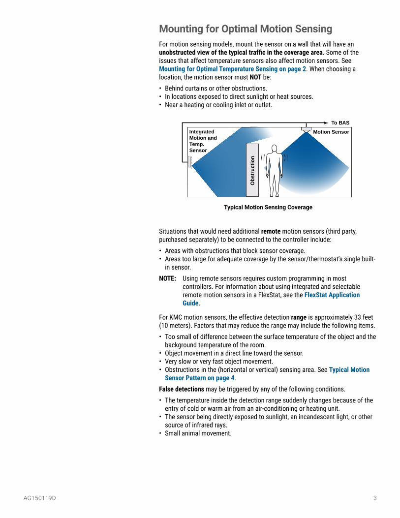
Motion SensorIntegrated Motion and Temp. Sensor
Ob
stru
ctio
n
To BAS
Typical Motion Sensing Coverage
Mounting for Optimal Motion SensingFor motion sensing models, mount the sensor on a wall that will have an unobstructed view of the typical traffic in the coverage area. Some of the issues that affect temperature sensors also affect motion sensors. See Mounting for Optimal Temperature Sensing on page 2. When choosing a location, the motion sensor must NOT be:• Behind curtains or other obstructions.• In locations exposed to direct sunlight or heat sources.• Near a heating or cooling inlet or outlet.
Situations that would need additional remote motion sensors (third party, purchased separately) to be connected to the controller include:• Areas with obstructions that block sensor coverage.• Areas too large for adequate coverage by the sensor/thermostat’s single built-
in sensor.NOTE: Using remote sensors requires custom programming in most
controllers. For information about using integrated and selectable remote motion sensors in a FlexStat, see the FlexStat Application Guide.
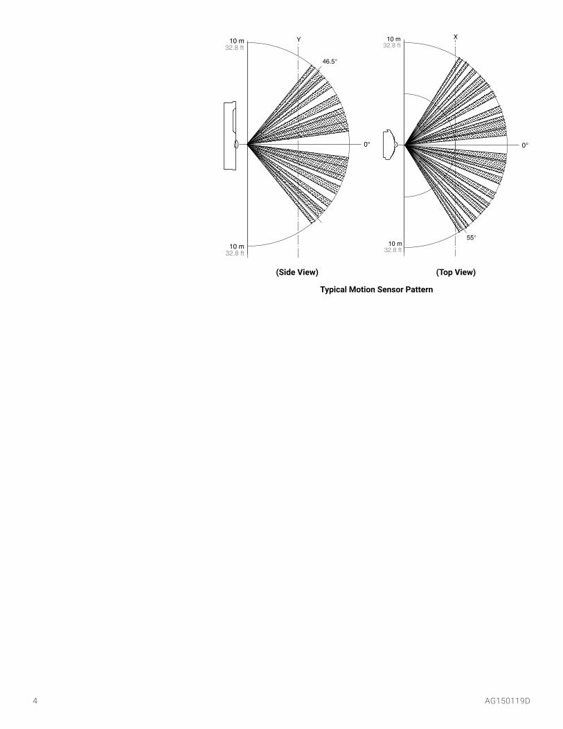
For KMC motion sensors, the effective detection range is approximately 33 feet (10 meters). Factors that may reduce the range may include the following items.• Too small of difference between the surface temperature of the object and the
background temperature of the room.• Object movement in a direct line toward the sensor.• Very slow or very fast object movement.• Obstructions in the (horizontal or vertical) sensing area. See Typical Motion
Sensor Pattern on page 4.False detections may be triggered by any of the following conditions.• The temperature inside the detection range suddenly changes because of the
entry of cold or warm air from an air-conditioning or heating unit.• The sensor being directly exposed to sunlight, an incandescent light, or other
source of infrared rays.• Small animal movement.
4 AG150119D
�������
�������
�����������
�
��
�����������
�����������
��
�����
�
Typical Motion Sensor Pattern
(Side View) (Top View)

AG150119D 5
Mounting Components and Height
Mounting HeightTraditionally, thermostats and room temperature sensors have been mounted approximately 60 inches (152 cm) from the floor. This has been considered an effective height to measure the room temperature and to allow a person to adjust a setpoint while standing.
However, for thermostats (and sensors with adjustable setpoint controls), the Americans with Disabilities Act (ADA) has rules to ensure that public lodging spaces and facilities remain accessible to the disabled. (They do not apply to private homes that rent fewer than five rooms.) To ensure that people in wheelchairs can reach and adjust the setpoint without assistance, ADA rules specify thermostat placement to be no higher than 48 inches (121 cm) above the floor (assuming no other obstructions are below it).
BEFORE running conduit and installing a thermostat, check the specific details of any applicable compliance requirements!
Backplate
Electrical Box
Optional Insulating GasketSealant Plugging Conduit and Other Holes
Cover
Approximately 60 Inches
(Traditional)
48 Inches Max. (ADA)
6 AG150119D
Reducing Temperature Sensing Errors• Air movement between the conditioned space and the conduit and/or wall cav-
ity can skew sensor readings. Apply sealant inside the conduit and other holes to block air leakage. See Mounting Components and Height on page 5.
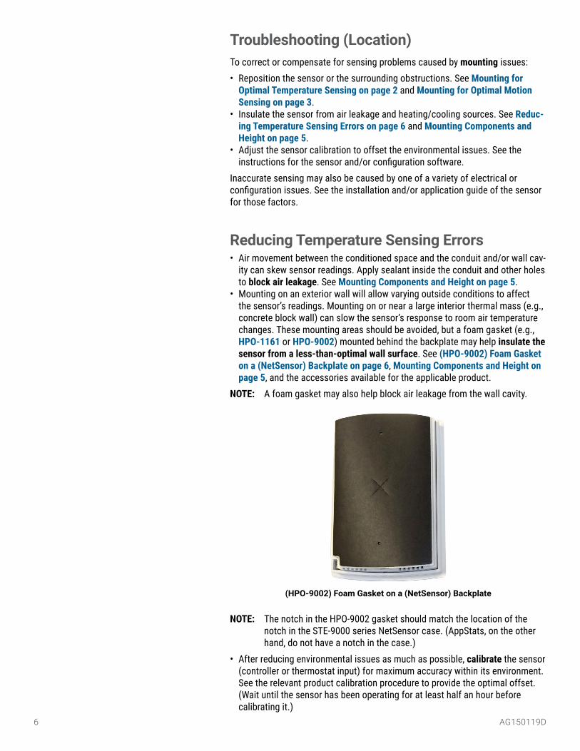
• Mounting on an exterior wall will allow varying outside conditions to affect the sensor’s readings. Mounting on or near a large interior thermal mass (e.g., concrete block wall) can slow the sensor’s response to room air temperature changes. These mounting areas should be avoided, but a foam gasket (e.g., HPO-1161 or HPO-9002) mounted behind the backplate may help insulate the sensor from a less-than-optimal wall surface. See (HPO-9002) Foam Gasket on a (NetSensor) Backplate on page 6, Mounting Components and Height on page 5, and the accessories available for the applicable product.
NOTE: A foam gasket may also help block air leakage from the wall cavity.
(HPO-9002) Foam Gasket on a (NetSensor) Backplate
NOTE: The notch in the HPO-9002 gasket should match the location of the notch in the STE-9000 series NetSensor case. (AppStats, on the other hand, do not have a notch in the case.)
• After reducing environmental issues as much as possible, calibrate the sensor (controller or thermostat input) for maximum accuracy within its environment. See the relevant product calibration procedure to provide the optimal offset. (Wait until the sensor has been operating for at least half an hour before calibrating it.)
Troubleshooting (Location)To correct or compensate for sensing problems caused by mounting issues:• Reposition the sensor or the surrounding obstructions. See Mounting for
Optimal Temperature Sensing on page 2 and Mounting for Optimal Motion Sensing on page 3.
• Insulate the sensor from air leakage and heating/cooling sources. See Reduc-ing Temperature Sensing Errors on page 6 and Mounting Components and Height on page 5.
• Adjust the sensor calibration to offset the environmental issues. See the instructions for the sensor and/or configuration software.
Inaccurate sensing may also be caused by one of a variety of electrical or configuration issues. See the installation and/or application guide of the sensor for those factors.

AG150119D 7
MaintenanceTo maintain accurate temperature and humidity sensing, remove dust as necessary from the ventilation holes in the top and bottom of the case.
To clean the case or display, use a soft, damp cloth (and mild soap if necessary).
To maintain maximum sensitivity of the built-in motion sensor, occasionally wipe dust or dirt off the lens—but do not use any fluid on the sensor.
CO2 sensors designed for continuous occupation applications, such as in the BAC-14xxxx FlexStats, require periodic calibration with gas to maintain long-term accuracy. See the CO2 calibration section in the FlexStat Application Guide for more information.
NOTE: BAC-13xxxx FlexStats and most other KMC CO2 sensors are designed to operate in areas where CO2 levels periodically fall to outside levels during unoccupied periods. Such models self-calibrate over time, and calibrating them with gas may not be necessary or even feasible.
Clean Case Holes and Surface
Clean Motion Sensor

8 AG150119D© 2017 KMC Controls, Inc. Specifications and design subject to change without notice AG150119D
SupportAdditional resources for product specifications, installation, configuration, application, operation, programming, upgrading and much more are available on the KMC Controls web site (www.kmccontrols.com). To see all available files, log-in to the KMC Partners site.
Important NoticesThe KMC logo and KMC Controls are registered trademarks of KMC Controls, Inc. Other products and name brands mentioned may be trademarks of their respective companies or organizations.
All rights reserved. No part of this publication may be reproduced, transmitted, transcribed, stored in a retrieval system, or translated into any language in any form by any means without the written permission of KMC Controls, Inc.
The material in this document is for information purposes only. The contents and the product it describes are subject to change without notice. KMC Controls, Inc. makes no representations or warranties with respect to this document. In no event shall KMC Controls, Inc. be liable for any damages, direct or incidental, arising out of or related to the use of this document.