Embed Size (px)
Citation preview

Table of
Introduction . . . . . . . . . . . . . . . . . . . . . . . . . . . . . . . . . ...3Nomenclature . . . . . . . . . . . . . . . . . . . . . . . . . . . . . . ...3
Unit Description . . . . . . . . . . . . . . . . . . . . . . . . . . . . . ...3Typical Component Locations . . . . . . . . . . . . . . . . . . ...4Typical Unit Sections . . . . . . . . . . . . . . . . . . . . . . . . . ...4Refrigeration Piping . . . . . . . . . . . . . . . . . . . . . . . . . ...5Condenser Fan Arrangement . . . . . . . . . . . . . . . . . . ...9Refrigeration Circuit Schematic . . . . . . . . . . . . . . . ...10Control Locations . . . . . . . . . . . . . . . . . . . . . . . . . . . ...10Control Panel Locations . . . . . . . . . . . . . . . . . . . . . ...11Controls, Settings, and Functions . . . . . . . . . . . . . . ...15
Mechanical installation . . . . . . . . . . . . . . . . . . . . . . . ...18Receiving Inspection . . . . . . . . . . . . . . . . . . . . . . . . ...18Unit Clearances . . . . . . . . . . . . . . . . . . . . . . . . . . . . ...18Roof Curb Assembly and installation.. . . . . . . . . . ...20Post and Rail Mounting . . . . . . . . . . . . . . . . . . . . . ...23Rigging and Handling . . . . . . . . . . . . . . . . . . . . . . . ...23Reassembly of Split Units . . . . . . . . . . . . . . . . . . . ...26Installing Ductwork . . . . . . . . . . . . . . . . . . . . . . . . . ...35Installing Duct Static Pressure Sensor Taps . . . . . ...35Installing Building Static Pressure Sensor Taps . . ...36Condensate Drain Connection . . . . . . . . . . . . . . . . ...37Unit Piping . . . . . . . . . . . . . . . . . . . . . . . . . . . . . . . . ...38Cabinet Weatherproofing . . . . . . . . . . . . . . . . . . . . ...39
Electrical installation . . . . . . . . . . . . . . . . . . . . . . . . ...40Field Power Wiring . . . . . . . . . . . . . . . . . . . . . . . . . ...40Field Control Wiring . . . . . . . . . . . . . . . . . . . . . . . . ...43
Readying Unit for Operation. . . . . . . . . . . . . . . . . . ...44Spring lsolatecl Fans . . . . . . . . . . . . . . . . . . . . . . . . ...44Seismic Restraints . . . . . . . . . . . . . . . . . . . . . . . . . ...45Spring Isolated Compressors . . . . . . . . . . . . . . . . . ...46Refrigeration Service Valves . . . . . . . . . . . . . . . . . . ...46
Sequences of Operation . . . . . . . . . . . . . . . . . . . . . . ...47Power-up . . . . . . . . . . . . . . . . . . . . . . . . . . . . . . . . . ...47Fan Operation . . . . . . . . . . . . . . . . . . . . . . . . . . . . . ...47Economizer Operation . . . . . . . . . . . . . . . . . . . . . . ...48Mechanical Cooling Operation . . . . . . . . . . . . . . . . ...48Heating Operation . . . . . . . . . . . . . . . . . . . . . . . . . . ...50
Wiring Diagrams . . . . . . . . . . . . . . . . . . . . . . . . . . . . ...51Legend . . . . . . . . . . . . . . . . . . . . . . . . . . . . . . . . . . . ...51Typical Power Circuits . . . . . . . . . . . . . . . . . . . . . . . ...52Typical Main Control Circuit (VAV Units) . . . . . . . . ...54Typical Main Control Circuit (CAV-ZTC Units) . . . . ...55Typical Main Control Circuit (CAV-DTC Units) . . . . ...56Typical Actuator Control Circuit . . . . . . . . . . . . . . . ...57
Contents
Typical Supply/Return Fan Control Circuit . . . . . . . ...57Typical Condenser Control Circuit
(2-Compressor/4-Stage). . . . . . . . . . . . . . . . . . . . ...58Typical Condenser Control Circuit
(4-Compressor/8-Stage) . . . . . . . . . . . . . . . . . . . . ...59Typical Gas Furnace Control Circuit
(Modulating Burner, Mixed Air Intake) . . . . . . . . ...60Typical Electric Heat Control Circuit (Multistage) . ...61
Unit Options . . . . . . . . . . . . . . . . . . . . . . . . . . . . . . . . ...62Enthalpy Control . . . . . . . . . . . . . . . . . . . . . . . . . . . ...62Part Winding Start . . . . . . . . . . . . . . . . . . . . . . . . . . ...62Low Ambient Start . . . . . . . . . . . . . . . . . . . . . . . . . . ...62Ground Fault Protection . . . . . . . . . . . . . . . . . . . . . ...63Phase Voltage Monitor . . . . . . . . . . . . . . . . . . . . . . ...63Hot Gas Bypass . . . . . . . . . . . . . . . . . . . . . . . . . . . ...63SpeedTrol . . . . . . . . . . . . . . . . . . . . . . . . . . . . . . . . . ...64Remote Monitor Panel . . . . . . . . . . . . . . . . . . . . . . ...65Optional Remote Monitoring and Control Panel . . ...66External Time Clock . . . . . . . . . . . . . . . . . . . . . . . . ...66Smoke Detectors . . . . . . . . . . . . . . . . . . . . . . . . . . . ...66Freeze Protection . . . . . . . . . . . . . . . . . . . . . . . . . . ...66Mixed Air Temperature Alarm . . . . . . . . . . . . . . . . . ...67Duct High Pressure Limit . . . . . . . . . . . . . . . . . . . . ...67Variable inlet Vanes, . . . . . . . . . . . . . . . . . . . . . . . . ...67Convenience Receptacle/Section Lights . . . . . . . . ...70
Check, Test, and Start Procedures . . . . . . . . . . . . . ...71Before Start-up . . . . . . . . . . . . . . . . . . . . . . . . . . . . ...71Power-up . . . . . . . . . . . . . . . . . . . . . . . . . . . . . . . . . ...71Fan Start-up . . . . . . . . . . . . . . . . . . . . . . . . . . . . . . . ...72Economizer Start-up . . . . . . . . . . . . . . . . . . . . . . . . ...72Compressor Start-up . . . . . . . . . . . . . . . . . . . . . . . . ...72Heating System Start-up . . . . . . . . . . . . . . . . . . . . . ...74Air Balancing . . . . . . . . . . . . . . . . . . . . . . . . . . . . . . ...74Final Contra! Settings . . . . . . . . . . . . . . . . . . . . . . . . ..~
Maintenance . . . . . . . . . . . . . . . . . . . . . . . . . . . . . . . . ...81Preventative Maintenance . . . . . . . . . . . . . . . . . . . . ...81Gas Furnace . . . . . . . . . . . . . . . . . . . . . . . . . . . . . . ...81Bearing Lubrication . . . . . . . . . . . . . . . . . . . . . . . . . ...81Setscrews . . . . . . . . . . . . . . . . . . . . . . . . . . . . . . . . ...82Airfoil Supply Fan Wheel-to-Funnel Alignment . . . ...82Winterizing Water Coils, . . . . . . . . . . . . . . . . . . . . . ...83
Service and Warranty Procedure . . . . . . . . . . . . . . ...83Compressor . . . . . . . . . . . . . . . . . . . . . . . . . . . . . . . ...83In-Warranty Return Material Procedure . . . . . . . . . ...83Replacement Parts . . . . . . . . . . . . . . . . . . . . . . . . . ...83
Product Warranty . . . . . . . . . . . . . . . . . . . . . . . . . . . ...84
Installation and maintenance are to be performed only by qualified personnel who are familiar with local codesand regulations, and experienced with this type of equipment. CAUTION: Sharp edges and coil surfaces are apotential injury hazard. Avoid contact with them.
Page 2 I IM 485


Typical Component
Figure 1 shows a typical RPS unit with the location of the major components and also lists some major dimensions for variousunit sizes. These figures are for reference only. See the certified submittals for actual specific dimensions.
Figure
\
OPTIONAL EXHAUSTDAMPERS
CONDENSER CONTROL PANEL
OPTIONAL RETURN SUPPLY AIR FANAIR FAN
~ MAIN CONTROL PANEL“1, 1 ) i , ,.,1
[‘~~~$~&$=T~~Z2~;;;ALGAS
OPTIONAL BACK RETURN AIR OPENING 93.5” (2375 mm) STEAM, HOT WATER, ELECTRIC)
LONG
\Unit Size
Dimensions in Inches
“A” “B” “c” s’~>.
RPS-045C – 075C 38 (965mm) 28 (711 mm) 73 (1854 mm) 31.8 (808mm)
RPS-080C– 090C 62 (1575 mm) 38 (965mm) 97 (2464 mm) 41.8 (1062 mm)
RPS-105C – 135C 62 (1575 mm) 46 (1168mm) 97 (2464 mm) 41.8 (1062 mm)
Typical Unit Sections
The individual sections that make up a rooftop can vary from unit to unit. All available sections are shown below in Figure 2.
Figure 2. Typical Unit Sections
RETURN AIR
OMHOOD -
aPLENUM
c130% OA
DECONOM12EF
laECONCYUA
s
Page 4 I IM 485
FILTER
TMM
n6W5
D,!,,,,SmGonBUNK
n8LANK
o
BUNK(WT.)
oc15A FAN
.*
❑./
HEAT
>
S.!HW
D,1,,,,
ELECT
c1,1II,,
GAS
uBLANK
El/
BUNK(OPT )
[
>
n2
COIL-=
FM
c1,!t,,,
STAGG
u->
FINALFILTER(OPT )
FIAT
II1,,,u
5TAGG
KBUNK
mBLANK
5
,LENUM ‘#--
n..
CONCENSER
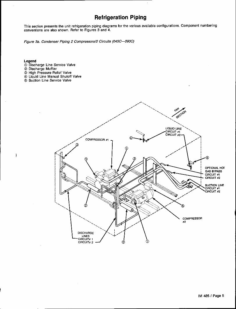
Refrigeration Piping
This section presents the unit refrigeration piping diagrams for the various available configurations. Component numberingconventions are also shown. Refer to Figures 3 and 4.
Figure 3a. Condenser Piping 2 Compressors/2 Circuits (045C–090C)
Legend@ Discharge Line Service Valve@ Discharge MufflerCDHigh Pressure Relief ValveO Liquid Line Manual Shutoff Valve@ Suction Line Service Valve
,fl.,/ \,
/ \,/“ \,
,/” N<
/
*F+,/ \
‘\\ *C6’0*,//,/0
//“
,/0 LIQUID LINE ‘%>>
0,/”
0’ COMPRESSOR #1
.-’;5.”?0“;;
.0” 1
K:iiiiiiiiiI. .
\,\
‘x
,,,’:>%;,, --.,::>,..&- /“ ‘CIRCUIT #2..:.’..:?. ./
‘\,
M\-....’-...;, ,.’
\, 0
\\ /“\\
L, /“\\ /“
\ ,0”‘N I
DISCHARGELINES “i””
\ COMpRESSOR
#2
“J ~ b— CIRCUIT# 1CIRCUIT# 2
IM 485 I Page 5
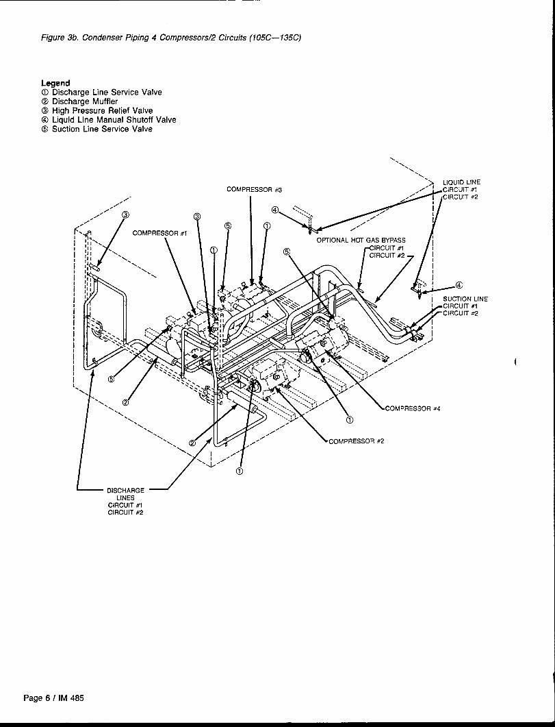
Figure 3b. Condenser Piping 4 Compressors/2 Circuits (105C–135C)
LegendDischarge Line Service ValveDischarge MufflerHigh Pressure Relief ValveLiquid Line Manual Shutoff ValveSuction Line Service Valve
N,
\
‘\,\\
> LIQUID LINE#l*2
LINE#1#2
LINESCIRCUIT #1CIRCUIT #2
(
Page 6 I IM 485

Figure 4a. Air Handler Piping (Flat DX)
LegendO Filter-Drier@ Liquid Line Solenoid Valve@ Sightglass@ Hot Gas Bypass Solenoid Valve (Optional)0 Hot Gas Bypass Valve (Optional)@ Thermostatic Expansion Valve@ Distributor
CIRCUIT #2 -
cONDENSER
/
SECTION
LIQUID LINECIRCUIT #1
OPTIONAL HOT‘%wl%--f>p‘
SUOTION LINEg
\
CIRCUIT #1@
CIRCUIT #2
IM 4851 Page 7
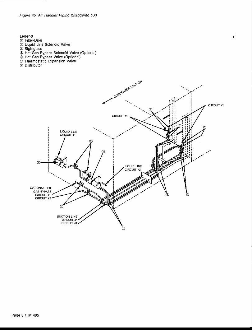
Figure 4b. Air Handler Piping (Staggered DX)
Legend0 Filter-Drier@ Liquid Line Solenoid Valve@ Sightglass@ Hot Gas Bypass Solenoid Valve (Optional)@ Hot Gas Bypass Valve (Optional)@ Thermostatic Expansion Valve@ Distributor
Page 8 I IM 485
CIRCUIT *1
..-
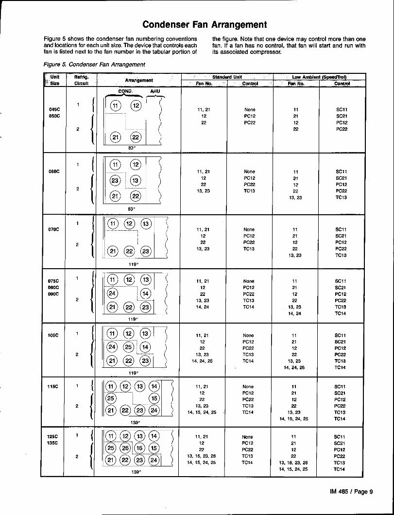
Condenser Fan Arrangement
~ Figure 5 shows the condenser fan numbering conventions the figure. Note that one device may control more than oneand locations for each unit size. The device that controls each fan. If a fan has no control, that fan will start and run withfan is listed next to the fan number in the tabular portion of its associated compressor.
Figure 5. Condenser Fan Arrangement
Unit Refrig.Arrangement I
Standard Unit I LowAmbient (Spead%o )I**-- AI—. 4. --- .,- 4.-- . . . . --- ..- ---.—.=Ize Wnarn ran No. Wnm?l mm rw. wrnrut
COND. AHU
045C 1( @ @—11,21 None
{ ml
11 Scl 1
050C 12 PC12 21 SC21
22 PC22 12 PC12
2
@ k“
22 PC22
83”
060C1( @)@
{ ED
11, 21 None 11 Scl 1
@~@
12 PC12 21 SC21
222 PC22 12 PC12
@I”@
13, 23 TC13 22 PC22
13, 23 TC13
63”
070C 1( @@@ None ,,
{ I-R
11,21 Scl 1
12 Pcl 2 21 SC21
2 22 PC22 12
@ @ ‘“””@””
PC12
13, 23 TC13 22 PC22
13, 23 TC13
119”
075C 1( @)@@ 11, 21 None 11 Scl 1
080C
{ ml
. .......
@ Ii)
12 PC12 21 SC21
090C 22 PC22 12 PC122 ................... 13, 23 TC13 22
@@@
PC22
14, 24 TC14 13, 23 TC13
14, 24 TC14119”
105C 1[ @)@@ 11,21 None 11 Scl 1.. . . .
{ n
@ @l@
12 PC12 21 SC21
22 PC22 12 Pcl 2
2 .................
@@@
13, 23 TC13 22 PC22
14, 24, 25 TC14 13, 23 TC13
14, 24, 25 TC14119”
“5C j ml ,4,:,25 g ,4,,;:,25 ;
139”
‘z j RI ,:::: g ;:,6;,: :“@-”@m@ @
139” ,,,
IM 485 I Page 9

Refrigeration Circuit SchematicLegend
CompressorSecond Compressor (4 Compressor Units)Discharge LineCondenser CoilEvaporator CoilManual Shut-off ValveFilter-DrierLiquid Line Solenoid ValveSightglassLiquid LineSuction LineThermostatic Expansion ValveDistributorHot Gas Bypass Solenoid Valve (Optional)Hot Gas Bypass Lines (Optional)Hot Gas Bypass Valve (Optional)
ControlFigure 6 shows the locations of the various control com-ponents mounted throughout the unit. See “Control PanelLocations” for the locations of control components mountedin control panels. Additional information is included in Table
Figure 6. Control Locations
h I
‘t+?”Im_
c
ill’Locations
2, “Controls, Settings, and Functions;’ and the wiring diagramlegend which is included in the “Wiring Diagrams” sectionof this manual.
CONDENSER SECTION ~ /PC12, 22
SC1l, 21 (OPTIONAL)
DISC. PLENUM SECTION CII, 12 (OPTIONAL)
DX SECTION Svl 2
HEAT SECTION
\SUPPLY FAN SECTiON q
FILTER SECTION
HTIW-4 AND
\\1,
,--—iU2 (OPTIONAL)
(OPTIONAL)
C9, 10(OPTIONAL)
ACTOPTIONAL)
LT1l (OFTIONAL) /
I
L RAE (OPTIONAL)S11, RECI1
\S1O: REC1O(OPTIONAL)
Page
L SD2 (OPTIONAL)
10 / IM 485

Control Panel LocationsThe unit control panels and their locations are shown in the following figures. These figures show a typical unit configuration.Specific unit configurations may differ slightly from these figures depending on the particular unit options.
AYppLyFANsEa’ON
,I
CONDENSER SECTION
ELECTRIC HEATCONTROL PANEL(OPTIONAL)
Main Control Panel
/
TB7
I
TB8
[
/ L.,, T#.-
1L CONDENSER CONTROL
— I-uSE BOX(OPTIONAL)
PANEL (RIGHT)
MAIN CONTROLPANEL L CONDENSER CONTROL
PANEL (LEFT)
I
i
\
\
“\..\..\...\< —
H
L______ -L_–– _____
Id.1
e!zl “(.\.. ,i\“\ i
.’\ /“-.. .. ,/”~..+.. . .. ..,’-. ._ .._. ---
.------ —”-----.,- -,
/“. . .
,, . ./
‘II,/” --~:i ; &~, ““..% \i !\
:-: i-; --;
i-i i :--; o i\. A GFilGm2 /’,~\
/’ . . /“,.~.. ,/
~.. .,. . /-.. . . . . . ..- -
..~..*..
~..*..
~..>.,,, ..\,/
,!/I
i
i
i
i
I
I
I
I
I
\
\
\
— ‘.\
\\1
TB5 I
I
I
TB10 fI
illNB2
i
i— .,,.\ ,,/----
IM 485 / Page 11

Condenser Control Box
RPS: 2 Compressors (045C — 090C)
Note: Sizes 070C through 090C have a fuse box; FBI, FB2 and PVM2 move to this fuse box on these units.
II■ ■ ✍
F
——4——---__ ._ —__. .e- ..\
‘.\
. .\
. .\
. .\
.\..\
--------- -------- ------- .- -..-------~.. --”--- \------
.--”-. ..
. . \
\“” ~1 -;)--- .-
-.. ..-=.. -..~- #.-e----- -------
------- . . . . . . .._ . . . . . . -------
RPS: 4 Compressors (105C — 135C)
. . mu rB14 I>M3F’D32
WS2 e 0.
4.:+
0000
mlU’11-u -*,
o . .
Page 12 I IM 485
\------ ------ ------ .. _.. _-e----
/.”-. .-. .
-..----- --. =
. \
i
(-Eiza3’)’\. ...x ,
“.. .,-.. . . . . .- H.
---- --------------- - -. ._ .._ .. _.. - ..----- ”--

RCS: 2 Compressors (045C – 090C)
-mmF310 m4 F333 FS12
.0 0 D n
—-—A———-—b-—__- _____-=
‘+% 103 ,.\ ..
\“.
\. .
\‘.
\. .
\‘.
\------ ------ ------ .. ---- .---.----- ../.- “----- \
..-.. -.
/.. O- . -. ...
. . .
... .. #.-+.. - [email protected] ----
--------- .. . . .. .._ --------
RCS: 4 Compressors (105C — 135C)
~---- A .——.- —— —.-
. .
lB!
,
‘-l,,, ,.J
m4
.—---—-
‘4%
S!ziifr’”,\‘\----------- -—--------— -------------- ------- . .---- -.. \
----- -....- -.. = \,.
,,~
L./i\..\...
-, ‘..
P Lv!-li:qp” “q”.. .-,\...
i10) r~ -~ lqm 43JPF? I KC2 I . /’
. . /’”*.. .-”
-..i.
..-”----
--------
--------------------------- .. _.. _ .. _.. - ..-
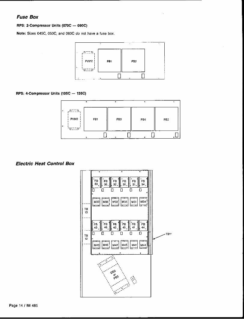
Fuse Box
RPS: 2-Compressor Units (070C — 090C)
Note: Sizes 045C, 050C, and 060C do not have a fuse box.
EIEIc1 El
RPS: 4-Compressor Units (105C — 135C)
Heat Control Box
o 0 .
EIE331EEE‘--- LbkMiTB
____
: EllE13EllHETB
-’:-- Lb;bb;
. . e
, . . ‘,:>,. ,#. .-\>,. i,,.
,-L, ,. ..~.x.\ --- ‘,
\ \‘.-”-’ o%~ ‘.,\
\ ~1 ,\\ @3 ,,:, :;<, ,J\\\ >.” . . . .\ ,. > ,<.\ .,
.,.’ ,.- ;’. .,. .(> .-,
.,, . ~,”,;~. -
/TB”

Controls,
.,
Settings, and FunctionsTable 2 presents a listing of all the unit control devices. Included in the table are the device symbol, a description of the device, its function, and any reset information, its location,any device setting, any setting ranges, differentials, and the device part number.
Table 2. Controls, Settings, and Functions!~ “ v&z~&pggri’ ~“-r’~~~ ,e- ~. . . . ~a~o - , .-, .q$g~~~.-.,..,. ~=. ..w>,.,!..
Csl & 2
~ ‘ “’”~“ -# .%-j
Switch (toggle), Shuts off compressor control circuits manually. NIA Condenser control box NIA NIA NIA 013550B-00refrigerant circuit
ADI ADI Board Collects and conditions analog and digital inputs. NIA Main control panel NIA NIA NIA 658160B-05
DHL Duct high limit Prevents excessive VAV duct pressures; shuts off fan. Auto Main control panel 3.5” WC. (871.8 Pa) 0.05-5.0” WC. 0.05” WC. 6549388-01(12.5-1245.4 Pa) (12.5 Pa), fixed
FS1 Freezestat Shuts off fans, opens heating valve and closes out- Auto Heating section 38° F or as required 35-45°F (2-70C) 120F (7°C), fixeddoor damper if low air temperature at coil is detected.
658300B-01(3”C)
HP1, 2, 3, &4 High pressure control Stops compressor when refrigerant discharge pressure is Manual Compressortoo high.
cut out = 400 psig NIA 100 psi (689 kPa) 473561B-10(relay (2758 kPa)latched) Cut in= 300 psig
(2068 kPa)
LP1 & 2 Low pressure control Stops compressor when suction pressure is too low Auto Compressor Cut out =35 psig NIA(used for pumpdown).
25 psi (172 kPa) 473561B-11(241 kPa)Cut in =60 psig(414 kPa)
MAT Mixed air temperature Senses mixed air temperature; sends signal to MicroTech NIA Inlet of supply fan NIA 3K ohms at 77°Fsensor controller.
NIA 658295B-03(25”C)
MCB1 Microprocessor Control Processes input information and controls output relays as NIABoard
Main control box NIA NIAappropriate.
NIA 654673B-08
MP1, 2, 3, &4 Compressor motor protector Senses motor winding temperature; shuts off compressor Auto at Compressor junction box 9K-18K ohms 700 ohms coldon hjgh temperature.
NIA 446915X-003400ohms
Enthalpy control Returns outside air dampers to minimum position when Auto Economizer section “B” or as required(electromechanical)
A—Denthalpy is too high.
Temp.: 3.5°F 307067D-02(2”C)Humid.: 5% fixed
OAE Enthalpy control Returns outside air dampers to minimum position when Auto(electronic)
Economizer section Fully CW past “D” A—D NIA 492622B-01outside air enthalpy is higher than return air enthalpy (when used with(used with RAE). RAE)
OAT Outside air temperature Senses outside air temperature; send signal to NIAsensor
Under condenser section NIAMicroTech controller.
3K ohms at 77°F NIA 658295B-02(25”C)
OBA, B, & C Output Boards A, B, or C Holds MicroTech solid-state output relays. NIA Main control box NIA NIA NIA 665422B-01(16 position)665422B-02( 8 position)665422B-03( 4 position)
OP1, 2, 3, &4 Oil pressure control Stops compressor when pressure drops below setpoint Manual Condenser control box Closes at 9 psi NIAfor 2 minutes.
5 psi (34.5 kPa) 473576B-04(62.1 kPa)Opens at 12-14 psi(82.7-96.5 kPa)
PC 5&6 Filter switch Turns on clogged filter light on status panel. Auto Filter sections As required 0.05-5 “ W.c. 0.05” W.c. 654936B-01(12.5-1245.4 Pa) (12.5 Pa)
Pc 7 Differential pressure switch Senses supply fan pressure to prove airflow. Auto Supply fan section 0.10” W.C. (25 Pa) .05-5.0” W.c, .05” WC. 654938B-01(12.5-1245.4 Pa) (12,5 Pa), fixed
zPC12 & 22 FanTrol switch (pressure) Cycles condenser fan to control head pressure. Auto Discharge headers Cut out= 170 psig NIA 120 psi (827 kPa) 473561B-18
*(1172 kPa)
wm
Cut in =290 psig(1999 kPa)
+-o
Psl & 2 Pumpdown switch Used to manually pump down compressor. NIA Condenser control box NIA NIA
PS3
NIA 013550B-00
8Master pumpdown switch Used to manually pump down all compressors. NIA Main control box NIA NIA
m
NIA 013550B-00
Continued on next pageAm

-u$ Table 2. Controls, Settings, and Functions (continued)
Symbol Description Function Reset Location Setting Renge Differentlel Pert # ~
m RAE Return air enthalpy sensor Used to compare return air enthalpy to outside air en- NIA Economizer section NIA NIA NIA 492622B-02. thalpy (used with OAE).
z RAT Return air temperature Senees return air temperature; sende signal to MicroTech NIA Return air section NIA 3K ohms at 77°F NIA
sensor
658295B-05
.P controller. (25”C)
% SAT Supply air temperature Senses discharge air temperature; sends signal to NIA Dkcharge air section
sensor
NIA 3K ohms at 77° F NIA
MicroTech controller.
656295B-01(25”C)
SBI & 2 Staging Board 1 or 2 Provides stepped cooling or heating control. NIA Main control box NIA NIA NIA See IM 483
Sell & 21 SpeedTrol control Varies condenser fan speed to control head pressure. NIA Condenser section NIA 170-230 psig, NIA 484452B-02(1172-1586 kPa) (60 Hz)
SD1
throttling
Smoke detector, supply air Initiates unit shutdown if smoke is detected. Manual Discharge air section NIA NIA NIA 490250B-01
SD2 Smoke detector, return air Initiates unit shutdown if smoke is detected. Manual Return air section NIA NIA NIA 490250B-01
SPS1 Duct static pressure sensor Converts static pressure signals to voltage signals and NIA Main control box NIA o to 5 “ WC. NIA 495450B-05
#l sends them to MicroTech controller (0-1245.4 Pa)1-6 VDC out
Duct static pressure sensor Converts static pressure signals to voltage signals and NIA Main control box NIA o to 5“ WC. NIA 495450B-05
#2 sends them to MicroTech controller. (0-1245.4 Pa)
SPS21-6 VDC out
Building static pressure Converts static pressure signals to voltage signals and NIA Main control box N/A -0.25 to 0.25” W.C. NIA
sensor
495450B-06
sends them to MicroTech controller. (-62.3 to 62.3 Pa)1-5 VDC out
SPS5 Dirty filter pressure sensor Senses pressure drop across first filter bank and sends NIA First filter section NIA o to 5“ WC. NIA 4954506-05
signal to MicroTech controller, (0-1245.4 Pa)1-6 VDC out
SPS6 Dirty filter pressure sensor Senses pressure drop across final filter bank and sends N/A Final filter section NIA
signal to MicroTech controller,
o to 5“ WC N/A 495450B-05(0-1245.4 Pa)1-6 VDC out
Svl & 2 Solenoid valve (liquid Iina) Closes liquid line for pumpdown. NIA Condenser section NIA NIA NIA See parts catalog
SV5 & 6 Solenoid valve (hot gas Closes hot gas bypass line for pumpdown. NIA Condenser section NIA NIA N/A 479313B-04
bypass)
S1 System switch Shuts off entire control circuit (except crankcase heaters). NIA Main control box NIA NIA NIA 013550B-00
TC13 & 14 FanTrol switch (temperature) Cycles condenser fan on ambient temperature. Auto Condenser control box As required 50-150 “F 5-20” F 654984B-01(10-66”C) (-15 to -7”C)
TD1 & 2 Compressor minimum off Prevents short cycling. Auto Condenser control box 5 min., fixed NIA N/A 282101D-O6
timer
TD5, 6, 7, & 8 Part winding start timer Reduces inrush amp draw on start-up. Auto Condenser control box 1 sec., fixed NIA N/A(compressor)
262101D-01
TD9 & 19 Part winding start timer Reduces inrueh amp draw on start-up. Auto Main control box 1 sec., fixed NIA NIA 282101D-O1
(fans)
TD1l & 12 Low ambient start timer Bypasses low pressure switch (LP’) until pressure Auto Condenser control box 2.75 min., fixed NIA NIAstabilizes.
323585B-00
ul&2 Cylinder unloader U:ed to load and unload compressors. N/A Compressor heads N/A NIA NIA See parts catalog
ZNT1, 2, & 3 Space temperature sensors Senses space temperature; sends signal to MicroTech fWA In building space NIA 3K ohms at i7° F NIAcontroller.
See IM 483(25”C)
Continued on next page
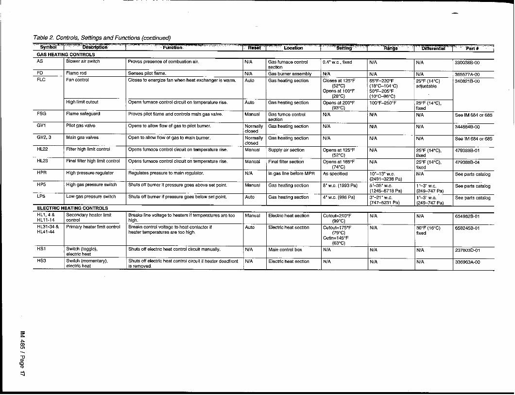
Table 2. Controls, Settings and Functions (continued)
z-Pcom\
FD
FLC
FSG
GVI
GV2, 3
HL22
HL23
HPR
HP5
LP5
ELECTRIC I
HLl,4&HLII-14
HL31-34 &HL41-44
HS1
HS3
- ----------Blower air switch I proves presence of combustion air. I NIA I Gas furnace control I 0.4” WC., fixed I NIA I NIA I 330038B-00
section
Flame rod Senses pilot flame. NIA Gas burner assembly NIA NIA NIA 365577A-00
Fan control Closes to energize fan when heat exchanger is warm. Auto Gas heating section Closes at 125°F 65”F–220”F 25°F (14”C)(52°C)
340821 B-00(18°C-1 04”C) adjustable
Opens at 100”F 50”F–205°F(28”C) (I O”C-96”C)
High limit cutout Opens furnace control circuit on temperature rise. Auto Gas heating section Opens at 200”F 10O”F–250”F 25°F(14°C),(93”C) Ifixed’ ‘“
Flame safeguard Proves pilot flame and controls main gas valve. Manual Gas furnce control I WA I NIA I NIA I See IM 684 or 685
IPilot gas valve
I section
I opens to allow fiow of gas to pilot burner. ~Normally I Gas heating section I NIA I NIA I NIA I 34t884B-00closed
Main gas valves Open to allow flow of gas to main burner. Normally I Gas heating section I NIA I NIA I NIA I See IM 684 or 685
I 1closed
Filter high limit control I Opens furnace control circuit on temperature rise. I Manual I Supply air section I Opens at 125°F I NIA I 25°F [14”C). I 479368B-01(52”C) fixed ‘ ‘”
Final filter high limit control Opens furnace control circuit on temperature rise. I Manual Final filter section I Opens at 165°F I NIA I 25”F (14”C),
I (74”C) I fixed
High pressure regulator I Regulates pressure to main regulator. I NIA I In gas line before MPR I As specified I 10’’–13 W.c. I NIA
479388B-04
See oarts cataloa(2491-3238 Pa)
.
High gas pressure switch Shuts off burner if pressure goes above set point. Manual Gas heating section 8“ W.C. (1993 Pa) 5“-35” W.c. 1“-3 W.c. See parts catalog(1245-8718 Pa) (249-747 Pa)
Low gas pressure switch Shuts off burner if pressure goes below set point, Auto Gas heating section 4“ WC. (996 Pa) 3“-21 “ W.C. 1“-3 W,c. See parts catalog(747-5231 Pa) (249-747 Pa)
:ATIN12Ct3NTRf31 S-......- ----- -----Secondary heater limit I Breaks line voltage to heaters if temperatures are toa I Manual I Electric heat section I Cutout=21 O“F I NIA I NIAcontrol high. (99”C)
Primaty heater limit control Breaks control voltage to heat contactor if Auto Electric heat sectian Cutout= 175°F NIAheater temperatures are too high.
30”F(16°C)(79”C) fixed
Cutin=145°F(63”C)
Switch (toggle), Shuts off electric heat control circuit manually. NIA Main control box NIA NIA NIAelectric heat
Switch (momentary), Shuts off electric heat control circuit if heater deadfront NIA Electric heat section NIA NIA NIAelectric heat is removed.
654962B-01
658245B-01
237803D-01
336963A-00
Mechanical Installation
The installation of this equipment shall be in accordance withthe regulations of authorities having jurisdiction and all ap-plicable codes. It is the responsibility of the installer to deter-mine and follow the applicable codes.
Note: Low head may lead to poor, erratic refrigerant feedcontrol at the thermostatic expansion valve. The units haveautomatic control of the condenser fans which should pro-vide adequate head pressure control down to50 F providedthe unit is not exposed to windy conditions. The systemdesigner is responsible for assuring the condensing sectionis not exposed to excessive wind or air recirculation.
Sharp edges are inherent to sheet metal pans, screws,clips, and similar items. Can cause personal injury.
This equipment is to be installed and operated only by an ex-
perienced installation company and fully trained personnel.
Exercise caution when servicing equipment.
Receiving InspectionWhen the equipment is received, all items should be careful- during shipment (salt is of particular concern), it should beIy checked against the bill of lading to be sure all crates and cleaned off when received. The carrier should also fill out acartons have been received. All units should be carefully in- Carrier Inspection Report. The McQuay International Trafficspected for damages when received. If any damage is notic- Department should then be contacted at (612) 553-5330.ed, the carrier should make the proper notation on the delivery The unit nameplate should be checked to make sure thereceipt acknowledging the damage. If the unit has gotten dirty voltage agrees with the power supply available.
Unit ClearancesService Clearance
Allow service clearance approximately as indicated in Figure
7 below. Also, it is recommended that a roof walkway be pro-vided to the rooftop unit and along at least the two sides of theunit that provide access to most controls and serviceablecomponents.
Figure Z Service Clearance
SERVICE CLEARANCE 72” (1829 mm)
\
(ALL THE WAY AROUND EXCEPTOVER DIM. ‘A”)
L LOCATION COOLING COIL. HEAT
ROOF WALKWAYMEDIUM & SUPPLY FAN SHAFTSERVICE CLEARANCE 96 ‘“ (2438 mm)
Notes:O For units with optional blank section between heat and evaporator section, increase “A” by 48” (1219mm).@ For units with the following optional sections, increase “B” as follows: optional compartment out of airstream, add 72” (1829mm);
optional final filters, add 48” (1219mm).
Page 18 I IM 485

Ventilation Clearance
Following are minimum ventilation clearance recommenda-tions. The system designer must consider each applicationand assure adequate ventilation. If this is not done, the unitwill not perform properly.
Unit(s) surrounded by a screen or fence:1. The bottom of the screen or fence should be at least one
foot above the roof surface.
2. The distance between the unit and the screen or fenceshould be as described in “Service Clearance” above.
3. The distance between any two units within the screen orfence should be at least 120 inches (3048mm).
Unit(s) surrounded by solid walls:1. If there are walls on one or two adjacent sides of the unit,
the walls may be any height. If there are walls on morethan two adjacent sides of the unit, the walls should notbe higher than the unit.
2. The distance between the unit and the wall should be atleast 96 inches (2438 mm) on all sides of the unit.
3. The distance between any two units within the walls shouldbe at least 120 inches (3048mm).
Do not locate outside air intakes near exhaust vents or othersources of contaminated air.
Figure 8. Overhead Clearance
If the unit is installed where windy conditions are common,wind screens should be installed around the unit, maintain-ing the clearances specified above. This is particularly im-portant to prevent blowing snow from entering outside air in-takes, and to maintain adequate head pressure control whenmechanical cooling is required at low outdoor air tempera-tures.
Overhead Clearance
1. Unit(s) surrounded by screens or solid walls shall have nooverhead obstructions over any part of the unit.
2. Area above condenser must be unobstructed in all installa-tions to allow vertical air discharge.
3. The following restrictions shall be observed for overheadobstructions above the air handler section (see Figure 8).
a.
b.
c.
There shall be no overhead obstructions above the fur-nace flue, or within 9 inches of the sides of the flue box.
Overhead obstructions shall be no less than 2 inches(51mm) above the top of the unit.
There shall be no overhead obstructions in the areasabove the outside air and exhaust dampers that are far-ther than 24 inches (610mm) from the side of the unit.
.
4“24” (610~m)MAX. P
2“ (51mm)
TOPOFUNIT +A~MINIMUM’
TO OVERHEADOBSTRUCTION
‘-124” (610mm)MAX.
IM 485 / Page 19

Roof Curb Assembly and Installation
The roof curb and unit must be located on a portion of theroof that can support the weight of the unit. The unit mustbe supported to prevent bending or twisting of the machine.
If building construction could allow the transmission ofsound and vibration into the occupied space, it is recommend-ed that the unit be located over a non-critical area. It is theresponsibility of the system designer to make adequate pro-visions for noise and vibration in the occupied space.
The curb and unit must be installed level within thetolerances specified in Figures 9a, 9b, and 9C to allow thecondensate drain to flow properly.
Integral supply and return air duct flanges are provided withthe RPS/RFS roof curb, allowing connection of ductwork to
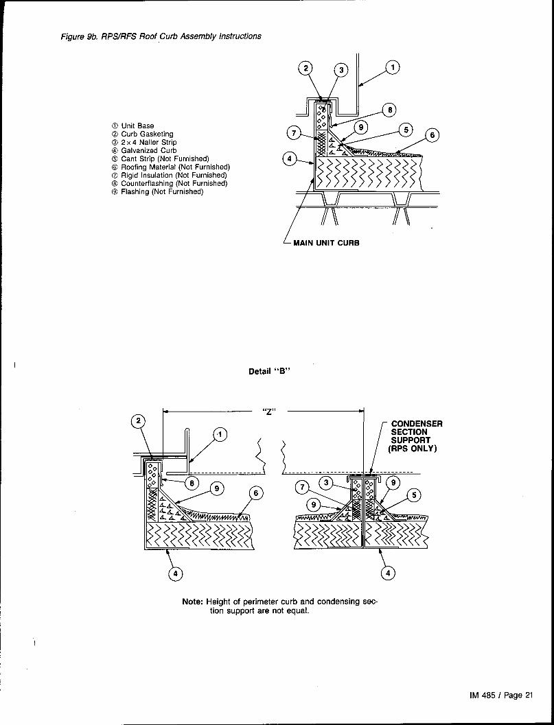
Figure 9a. RPS/RFS Roof Curb Assembly Instructions
the curb before the unit is set. The gasketed top surface ofthe duct flanges seals against the unit when it is set on thecurb. It is not recommended that these flanges support thetotal weight of the ductwork. Refer to the “installing Ductwork”section for details on duct connections. It is critical that thecondensate drain side of the unit be no higher than the op-posite side.
Assembly of a typical RPS roof curb is shown in Figures9a and 9b. Parts A through K are common to all units havingbottom return openings. Depending on the unit length, PartsL and M maybe included with the roof curb kit to create thecorrect overall curb Iength. Figure 9C shows the assemblv ofthe RCS roof curb. - -
Detail “A”
Using remaining side supports in thisarea, align lengths on opposite sides ofassembly and install a cross support “D”at each splice.
/
..
:&
:4
.,.. . ..
CONDENSER —SECTIONSUPPORT
/
1.2.
3.4.5.
6.
7.8.9.
Assembly Instructions:Set curbing parts A thru K per dimensions shown over roof opening or on a level surface. Note location of return and supply air openings.If applicable, set other curbing parts (D, L, M, etc.) in place making sure that the orientation agrees with the assembly instructions Checkalignment of all mating bolt holes. See Detail “A".Bolt curbing parts together using fasteners provided. Tighten all bolts finger tight.Square entire curbing assembly and securely tighten all bolts.Position curb assembly over roof openings. Curb must be level from side to side and over its length. Check that top surface of the curbis flat with no bowing or sagging.Weld curbing in place. Caulk all seams watertight. Remove backing from 0.25 (6mm) thick x 1.50 (38mm) wide gasketing and apply tosurfaces shown by crosshatching.Flash curbing into roof as shown in Detail “B”.Parts E and F are not required on units with no return shaft within the curb perimeter.Parts G and H are not required on units with no supply shaft within curb perimeter.
Page 20 I IM 485
I
Figure 9b. RPSYRFS Roof Curb Assembly Instructions
@ Unit Base@ Curb Gasketing02 x 4 Nailer Strip@ Galvanized Curb@ Cant Strip (Not Furnished)0 Roofing Material (Not Furnished)0 Rigid Insulation (Not Furnished)O Counterflashing (Not Furnished)@ Flashing (Not Furnished)
~ MAIN UNIT CURB
Detail “B”
/
CONDENSERSECTION
<
SUPPORT(RPS ONLY)
o4
Note: Height of perimeter curb andtion support are not equal.
b4condensing eec-
IM 485 I Page 21
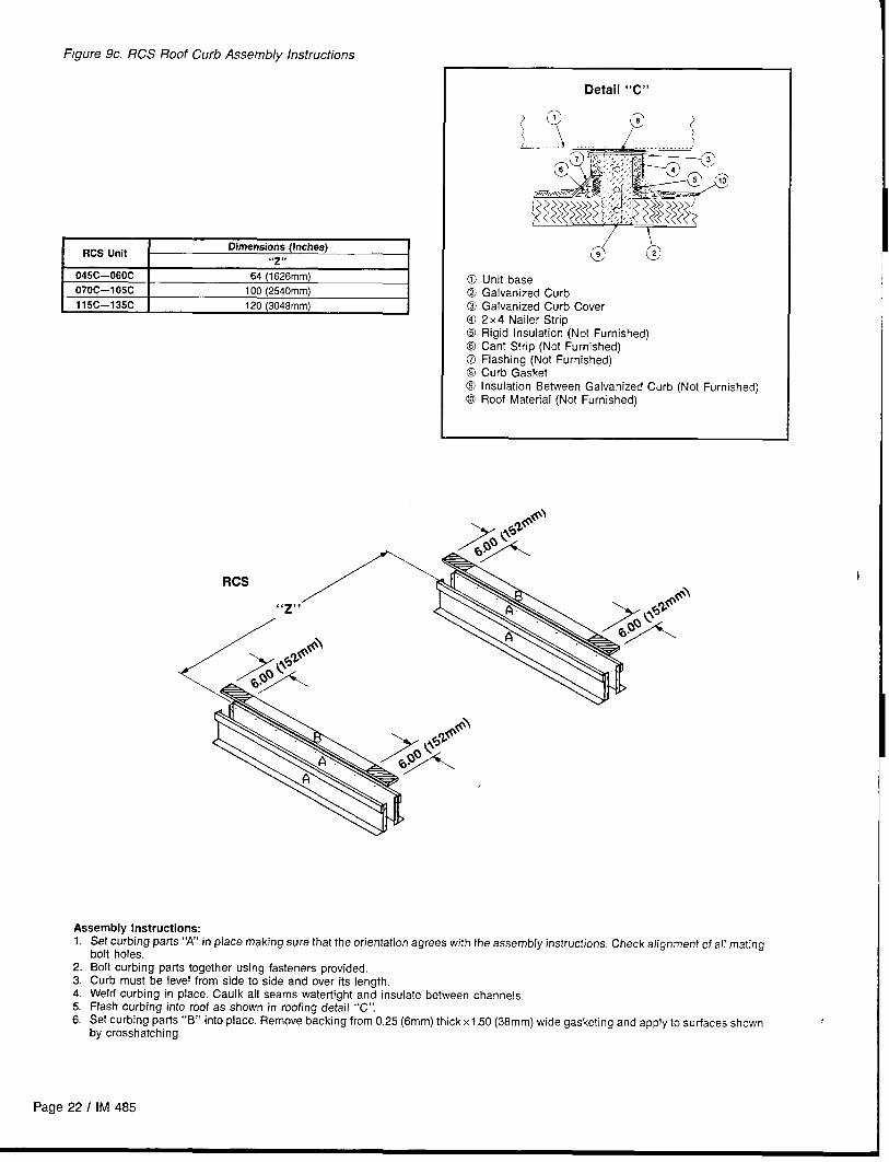
Figure 9c, RCS Roof Curb Assembly Instructions
I RCS Unit IDimensions (Inches)
“>,. I.045C–060C 64 (1626 mm)
070C–I05C 100 (2540 mm)
115C—135C 120 (3048 mm)
Detail “C”
@ Unit base@ Galvanized Curb@ Galvanized Curb Cover@ 2x4 Nailer Strip@ Rigid Insulation (Not Furnished)@ Cant Strip (Not Furnished)@ Flashing (Not Furnished)@ Curb Gasket(9 Insulation Between Galvanized Curb (Not Furnished)@ Roof Material (Not Furnished)
RCS
“~,,
Assemblv Instructions:1.
2.3.4.
5.6.
Set c~rbing parts “A” in place making sure that the orientation agrees with the assembly instructions. Check alignment of all matingbolt holes,Bolt curbing parts together using fasteners provided,Curb must be level from side to side and over its length.Weld curbing in place. Caulk all seams watertight and insulate between channels.Flash curbing into roof as shown in roofing detail “C”,Set curbing parts “B” into place. Remove backing from 0.25 (6mm) thick xl.50 (38mm) wide ~asketincl and amlv to surfaces shownby crosshatching,
.- .,.
Page 22 I IM 485

Post and Rail Mounting
When mounting by post and rail, the structural support should Figure 10. Post and Rail Mountingbe run the full length of the unit to prevent any deflection ofthe cabinet. The structural member should be located at thebase of the unit as shown in Figure 10 assuring the shadedarea is well supported by the structural member.
(
To assure proper system operation, it is important that the ~ ~ tunit is mounted level.
The post and rail setup should be done so that the unit is levelfrom side to side and over its entire length.
If resilient material is placed between the unit and the rail,insert a heavy steel plate between the unit and the resilient r L
material to distribute the load. Cabinet penetrations (electrical,------ ---- --- - ---
piping, etc.) should be sealed in a professional manner to pro- “ Maximum recommended width for structural member is 5“
tect against moisture and weather. (127mm) to allow for adequate space for duct connections andelectrical entry.
Rigging and Handling
Lifting brackets with 2 inch (51mm) diameter holes are pro- If the unit must be stored at the construction site for an in-vided on the sides of the unit. termediate period, set the unit in a reasonably level position
Use spreader bars, 101 (2565 mm) to 105 (2667mm) inches with adequate support. Protect the condenser coils, as theywide, to prevent damage to the unit cabinet. Avoid twisting are easily damaged.or uneven lifting of the unit. The cable length from the bracket Figure-ll shows an example of the rigging instruction labelto the hook should always be longer than the distance bet- shipped with each unit.ween the outer lifting points.
Figure 11. Rigging and Handling Instruction Label
RIGGING AND HANDLING INSTRUCTIONS
Unit has either four or six lifting points. (Six point shown below).
CAUTION: ALL LIFTING POINTS MUST SE USED.
Note: Rigging cables must be at Ieaat as long as distance %!’
LIFT ONLY AS INDICATED
IM 485 I Page 23

Lifting PointsTo determine the required lifting cable lengths and whetherfour- or six-point lifting is required, use Tables A and B belowand Figure 12.
Referring to Figure 12, note that Dimension A is thedistance between the outer lifting points. The four outer rig-ging cables must be equal to or longer than Dimension A.Dimension B shows the minimum distance between the outerand the inner lifting points for six-point lifting. This can beused to roughly determine the required length of the middlecables for six-point lifting. Dimension A can be determinedby subtracting Dimensions X and Y from Dimension Z (i.e.,A= Z-X-Y).
Table A. “X” Dimension (See Figure 12)
Type of Economizer Seotion 045C – 075C 080C — 135C
1000/o OA o 0
Plenum 48” (1219 mm) 72” (1829 mm)
O — 30°10 OA 48” (1219 mm) 72” (1829 mm)
O — 1000/n Economizer 72” (1829mm) 96” (2438 mm)
O — 100VO Economizer
With Return Fan72” (1829 mm) 96” (2438mm)
Figure 12a. Unit type RPS (No Split)
Where:
Z = Total unit length in inches (refer to certified drawings forthis dimension.
X = Refer to Table A for this dimension (if not specified onFigure 12).
Y = Refer to Table B for this dimension (if not specified onFigure 12).
If A < 288 inches, (7315 mm) 4-point lifting is sufficient.If A > 288 inches, (7315 mm) 6-point lifting is required.
Table B. “Y” Dimension for Units with Condensers(See Figure 12)
K Unit SizeMy..
045C — 090C 39.5” (1003mm)
105C 305” ( 775mm)115C—135C 39.5” (1003mm)
4 Lifting Points 6 Lifting Points
I05C—135C: B (Min.) = 120” (3048 mm)
Figure 12b. Unit Type RFS or Air Handler Section From RPS Factory Split at Condenser
4 Lifting Points 6 Lifting Points
Page 24 I IM 485

4 Lifting Points I 6 Lifting Points
045C–060C: B070C–I 05C: B115C—135C: B
(~in,)= 5,,, ,1448mm)\x(Min) = 93” (2362 mm)(Min.) = 113” (2870 mm)
Figure 12d. Section With Fan From RPS Factory Split at Fan
4 Lifting Points 6 Lifting Points
NIA
4 LiWtng Points
NIA
Figure 12e. Section With Condenser From RPS Factory Split at Fan
X=o.
6 Lifting Points●
)I05C—I 15C: B (Min.)= 96” (2438mm)125C—135C: B (Min.)= 120” (3048mm)

Reassembly of Split Units
Although RoofPak units typically ship from the factory as com-plete units, they may be split at the factory in one of threepossible configurations.
1. The RFS air handler section and RCS condenser section
ship as two separate units, each with its own power sup-ply and unit nameplate, This configuration is ordered whenthe condenser is intended to remain remote from the airhandler because of space or structural constraints.
On all units except the RFS with end discharge, refrig-erant piping is stubbed out the exterior of the cabinet forconvenient field piping between the RCS and RFS units,and all necessary refrigeration components are provided.
2. The RPS unit factory split at the condenser ships as an
air handler section and a condenser section that will be
recoupled together on the roof. This configuration wouldbe ordered if a packaged RPS unit is desired, but cannotgo to the job site because of shipping length or weightlimitations. A single nameplate is attached to the airhandler section and power is fed to both sections throughthe main control box, as it would be in a nonsplit RPS unit.
All interconnecting piping and refrigeration componentsare provided so that when the sections are coupledtogether only field-provided couplings are required to con-nect the piping.
3. The RPS unit factory split at the fan ships as two pieces,split at the supply fan bulkhead, to be recoupled togetheron the roof. Like the RPS unit factory split at the condenser,this configuration would be ordered if shipping length orweight limitation prevented a packaged RPS from beingordered. Splitting at the fan has the advantage of leavingall factory refrigerant piping intact so field evacuation andcharging is not required.
A single nameplate is attached to the air handler sec-tion and power is fed to both sections through the maincontrol box, as it would be in a nonsplit RPS unit.
RFS Air Handler and RCS Condenser
Because the cabinetry is not recoupled in the field, only in-terconnecting refrigerant piping and control wiring is requiredbetween the two sections. Separate power supply wiring isprovided to each section (refer to the “Field Power Wiring”section of this bulletin).
Electrical connections of the 115V and 24V control wiringbetween the RCS and RFS are described in the “Field Con-trol Wiring” section of this bulletin.
Piping design, sizing, and installation information presentedin the “ASHRAE Handbooks” should be followed in the design
and installation of interconnecting piping. The RCS and RFSunits are intended to be set at the same elevation as close
as possible to each other to minimize refrigerant pressure
drop. The piping must be designed and installed to preventliquid refrigerant carryover to the compressor and to assurea continuous return of compressor oil from the system. Figures3 and 4 show the locations of suction, liquid, and hot gas lineconnections.
To service liquid line components, the manual shutoff valveis closed and refrigerant is pumped into the condenser.The pounds of refrigerant in the system may exceed thecapacity of the condenser, depending on the amount ofrefrigerant in the liquid lines between the RFS and RCSunits. Suitable means of containing the refrigerant isrequired.
On systems with optional hot gas bypass, it is importantthat the bypass solenoid valve be located on the RCS andnot on the RFS unit to prevent liquid return and damage
to the compressor.
Piping Recommendationsl.-
2.
3.
4.
5.
Use tvpe K or L clean copper tubinq. All ioints should bethoroughly cleaned and” brazed with high temperaturesolder.
Piping sizes should be based on temperature/pressurelimitations as recommended in the following paragraphs.Under no circumstances should pipe size be based strict-ly upon the coil or condensing unit piping connection size.
Suction line piping pressure drop should not exceed thepressure equivalent of 20 F ( -16.7” C) (3 psi) (20.7 kPa) per100 feet (30.5m) of equivalent pipe length. After the suc-tion line size has been determined, the vertical suctionrisers should be checked to verify that oil will be carriedup the riser and back to the compressor. The suction line(s)should be pitched in the direction of refrigerant flow andadequately supported. Lines should be free draining andfully insulated between the evaporator(s) and thecompressor.
Vertical suction risers should be checked using Table 3to determine the minimum tonnage required to carry oilup suction risers of various sizes.
The Iiquid line should be sized for a pressure drop not toexceed the pressure equivalent of 2&F (-16.7 CC) (6 psi)(41.4 kPa) saturated temperature. The RFS unit includesa factory installed filter-drier, solenoid valve, and sightglassin each liquid line, upstream of the thermostatic expan-sion valve.
Table 3. Minimum Tonnage (R-22) to Carry Oil UpSuction Riser at 40F Saturated Suction
Line Size
O.D.11~,, 13A ,, ls~ ~, 2%,, ,23~f, 31~ , 35A ,, 4:~ ,,
Minimum
Tons1.50 2.50 3.80 7.60 13.10 20.4 29.7 41.3
Holding ChargeThe RFS unit and RCS unit ship with a nitrogen holdingcharge. At the time the unit was received, a visual inspectionof the unit piping should have been made to be sure nobreakage had occured or that the fittings had not loosened.A pressure test on the RCS unit should indicate a positivepressure in the unit. If no pressure is evident, the unit willhave to be leak tested and the leak repaired. This should benoted and reported to the McQuay sales representative andfreight carrier if the loss is due to shipping damage.
Always vent piping to atmosphere before applying heat toremove brazed piping caps and plugs. Failure to do socould result in hazardous pressures within the refrigerantcircuit, possibly resulting in a dangerous explosion.
RCS—Vent to atmosphere by opening gauge ports at the com-pressors and liquid line shutoff valves. Make sure manualvalves are not backseated to shut off the gauge ports.
RFS—Vent to atmosphere by cutting off the process tubes onthe suction line caps.
Page 26 I IM 485

The RFS unit does not have gauge ports for pressuremeasurement. If no positive pressure is detected when cut-ting off the process tubes and removing the tubing caps, theunit should be leak tested as described above, after the in-terconnecting piping has been brazed in place. This test willalso confirm the integrity of the field braze joints.
Leak TestingIn the case of loss of the nitrogen holding charge, the unitshould be checked for leaks prior to charging the completesystem. If the full charge was lost, leak testing can be doneby charging the refrigerant into the unit to build the pressureto approximately 10 psig and adding sufficient dry nitrogento bring the pressure to a maximum of 125 psig. The unitshould then be leak tested with halide or electronic leak detec-tor. After making any necessary repair, the system should beevacuated as described in the following paragraphs.
A serious explosion could result from usingoxygento buildup pressure resulting in severe personal injury or death.
Do not use oxygen to build up pressure.
EvacuationAfter it has been determined that the unit is tight and thereare no refrigerant leaks, the system should be evacuated. The
Table 4, Pressure-Vacuum Equivalents
use of a vacuum pump with a pumping capacity of approxi-mately 3 cu. ft./rein. and the ability to reduce the vacuum inthe unit to at least 1 millimeter (1000 microns) is recom-mended.
1.
2.
3.
A mercury manometer or an electronic or other type ofmicron gauge should be connected to the unit at a pointremote from the vacuum pump. For readings below 1millimeter, an electronic or other micron gauge should beused.
The triple evacuation method is recommended and is par-ticularly helpful if the vacuum pump is unable to obtainthe desired 1 millimeter of vacuum. The system is firstevacuated to approximately 29 inches (740mm) of mercury.Enough refrigerant vapor is then added to the system tobring the pressure up to O pounds (O microns).
Then the system is once again evacuated to 29 inches(740mm) of vacuum. This procedure is repeated threetimes. This method can be most effective by holding systempressure at Opounds (Omicrons) for a minimum of 1 hourbetween evacuations. The first pulldown will remove about90% of the noncondensables, the second about 90% of
that remaining from the first pulldown, and after the third,only 1/10 of l% noncondensables will remain.
Table 4 below shows the relationship between pressure,microns, atmospheres, and the boiling point of water.
Microns PsisI
Inv,l,”, y,-–.
n I n 7
E Absoiute Pressure Above Zero I Vacuum Beiow one Atmosphere Approximate Soiling PointB-------- Mercury Fraction of of H20 at Each
yam) (inches) One Atmosphere Pressure (“F)
. . 760.00 29.921 — —
50 0.001 759.95 29.920 1/15,200 -50
100 0.002 759.90 29.920 “17,600 -40
150 0.003 759.85 29.920 1/5,100 -33
200 0.004 759.80 29.910 I 113,800 I -28
300 0.006 759.70 29.910 112,500 -21
500 0.009 759.50 29,900 1/1 ,520 -12
I 1,000 0.019 I 759.00 29.880 1/760 1
2,000 0.039 758.00 29.640 1/380 15
I 4,000 0.078 I 756.00 29,760 I 1/1 89 I 29
8,000 0.117 754.00 29.690 1/127 39 I6,000 0.158 752.00 29.600 1/95 46
10,000 0.193 750.00 29.530 1176 52
15,000 0.290 745,00 29.330 1/50 63
20,000 0.387 740.00 29.130 1138 72
30,000 0.580 730.00 28.740 1/25 S4
50,000 0.967 710.00 27.950 1/15 101
100,000 1.930 660.00 25.980 2/1 5 125
200,000 3.870 560.00 22.050 114 152
500,000 9.670 260.00 10.240 213 192
760,000 14.697 0 0 1 Atmosphere 212
Charging the SystemRCS units are leak tested at the factory and shipped with anitrogen holding charge. If the holding charge has been lostdue to shipping damage, the system should be charged withenough refrigerant to raise the unit pressure to 30 psig afterfirst repairing the leaks and evacuating the system.
1.
2.
After all refrigerant piping is complete and the system hasbeen evacuated, it can be charged as described in theparagraphs following. Connect the refrigerant drum to thegauge port on the liquid shutoff valve, and purge the charg-ing line between the refrigerant cylinder and the valve.Then open the valve to the midposition.
If the system is under a vacuum, stand the refrigerant drum
3.
4.
with the connection up, open the drum and break thevacuum with refrigerant gas.
With a system gas pressure higher than the equivalent ofa freezing temperature, invert the charging cylinder andelevate the drum above the condenser. With the drum inthis position and the valves open, liquid refrigerant will flowinto the condenser. Approximately 75%0of the total require-ment estimated for the unit can be charged in this manner.
After 75%0 of the required charge has entered the con-denser, reconnect the refrigerant drum and charging lineto the suction side of the system. Again purge the connect-ing line, stand the drum with the connection side up, andplace the service valve in the open position.
IM 485 / Page 27

Important: At this point, the charging procedure should be 2. Evaporator coil charge—refer to Table 5.interrupted and prestart checks made before attempting to 3. Charge for length of interconnecting piping installed bycomplete the refrigerant charge. field-refer to Table 6.
Note: Itis recommended that the total operating charge per Note: The systems consist of two refrigerant circuits contain-circuit be stamped on the unit nameplate for future reference. ing identical weights of refrigerant. The values shown in Tables
5 and 6 are for each circuit.Refrigerant ChargeEach unit is designed for use with R-22. The total charge per
Note: The total operating charge per circuit should not ex-
circuit is the sum of three values:ceed the pumpdown capacity per circuit, shown in Table 5.
1. Base unit charge less evaporator coil—refer to Table 5.
Table 5. Approximate Refrigerant Charge Per Circuit
Baae R-22 Charge
Unit Size Lb. Per Cirsuit (Leaa DX Coil)OX Coil R-22 Charga — Lb. per Circuit Condenser Pumpdowrr
DX=S” DX = L* DX=S’ OX= L“capaci~” (Lb. R-22)
045C 27 — 3 x No. of DX rows — 47
050C 29 30 3 x No of DX rows 31/2x No. of DX rows 49
060C 29 30 3 x No. of DX rows 3VZ x No. of DX rows 49
070C 34 35 3 x No. of DX rows 31/2x No. of DX rows 67
075C 34 35 9 x No. of DX rows 31/2x No. of DX rows 67060C 40 41 4 x No. of DX rows 41/2 x No. of DX rows 70090C 46 47 4 x No. of DX rows 41/2x No. of DX rows 80105C 50 51 4VZ x No. of DX rows 572 x No of DX rows 60115C 59 60 4VZ x No. of DX rows 5M x No. of DX rows 104
125C — 60 — 5VZ x No. of DX rows 104135C — 60 — 51/2x No. of DX rows 104
“DX coil configuration (S =Standard, L= Large) is identified by the 8th digit of the RPS or RFS model number, found on the unit nameplate For example. DX= Lfor unit model number RFS060CLY.“’Condenser pumpdown capacity is based on volume between condenser entrance and liquid line solenoid at 90’ F, 90% full.
Table 6. Weight of Refrigerant R-22 in Copper Lines (Pounds Per 100 Feet of Type L Tubing)
~Voluma Per 100 Feet
Weight of Refriqarant, Lbs.1100 FeetO.D. Line Size
in Cubic Feet Liquid @ 100 “FHot Gas @ 120” F Suction Gaa (Superheated to 85” F)
Cond. 200F 40” F
318 0.054 3.64 .202 .052 .077V2 0.100 7.12 .374 .098 .143
% 0.162 7.12 .605 .158 .232
% 0.336 24.0 1.260 .323 .48011A 0.573 40.8 2.140 .550 .8201ya 0.872 62,1 3.260 .839 1.2501ye 1.237 88.0 4.620 1.190 1.7702r/* 2.147 153.0 8.040 2.060 3.0+30278 3.312 236.0 12.400 3,180 4.72031A 4.728 336.0 17.700 4,550 6.75035A 6.398 456.0 24.000 6.150 9.1404% 8.313 592.0 31.100 8.000 11.190
RPS Factory Split at Condenser
Field reassembly of an RPS unit that has shipped split at thecondenser takes place in three phases:1. Setting the sections and mechanically recoupling the
cabinet.2. Reconnecting refrigerant piping.3. Reconnecting power and control wiring.
Setting the Sections and Cabinet ReassemblyThe steps required to set the unit and reassemble the cabinetare shown in Figures 13a-c. The following items should benoted:1.
2.
3.
Top cap on air handler section and wire cover on conden-sing section must be removed before sections are settogether. Refer to Step 1 in Figure 13a.Piping brackets and clamps on both sections should beloosened so refrigerant lines can be moved out of the wayto prevent interference and damage as the sections areset together. Refer to Step 1 in Figure 13a.If unit is to be post-and-rail mounted on a structural beamthat runs the full length of the unit, Step 2 (installation ofcondenser supports) may be omitted. In this case, the boltsand lifting brackets shown in Step 1 should be left in place.
Page 28 I IM 485
Reconnecting Refrigerant PipingAll refrigerant piping required to reconnect the two sectionsis provided so that, when the piping closures are cut off, pip-ing from the air handler and condenser sections will line up.Piping can then be connected using field supplied couplings.
Like the RFS/RCS units, both sections of the RPS split-at-condenser unit ship from the factory with a holding charge.Before removing the piping closures, the unit should be in-spected for line breakage or loosening of fittings, and it shouldbe pressure tested as described in the previous “HoldingCharge” section which is under “RFS Air Handler and RCSCondenser” above.
Leak testing, evacuation, charging the system, and refrig-erant charge requirements for the split-at-condenser unitshould be done per the procedures described in the “RFSAir Handler and RCS Condenser” section above,
Note: Refrigerant charge requirements for the RPS split-at-condenser can be determined from Table 5. Because no fieldinstalled refrigerant piping is required, the total charge percircuit is the sum of the base R-22 charge and the DX coilcharge.

Figure 13a. RPS Split at Condenser Reassembly (Part 1)
Step 1. Set main unit in place and prepare unit for reassembly as shown.
REMOVE TOP CAP ANDSAVE FOR STEP 4
7
LOOSEN PIPING CLAMPS
% z!!?%!%!? AcONDENs’NG”N’TMAIN UNIT
\
\
\\
/a ,0’ NOTE: WIRE COVER MUST BE‘ ‘./( REMOVED AND DISCARDED
Y
. .-1 L
BEFORE UNITS AREI REASSEMBLED.
\ REMOVE PIPING COVER AND DISCARD;\ REINSTALL SCREWS IN HOLES TO
\\\
PREVENT WATER LEAKAGE
SEE STEP 2 ~
\
L REMOVE BOLT ANDSAVE FOR STEP 2
\REMOVE BOLT ANDSAVE FOR STEP 4
i.- AFTER MAIN UNIT IS lN$JljjLLEo, REMOVE
LIFTING BRACKET ON BOTH SIDES ANDDISCARD: SAVE BOLTS FOR STEP 2
Step 2. Install condenser supports.
INSTALL CONDENSER SUPPORTON MAIN UNIT AS SHOWN WITHBOLTS SAVED FROM STEP 1 (TYP.BOTH SIDES OF UNIT); FILL UNUSEDHOLES IN UNIT BASE WITH BOLTSSAVED FROM STEP 1
IM 485 I Page 29

Figure 13b. RPS Split at Condenser Reassembly (Part 2)
Step 3. Set condensing unit in place.
FIRST LOWER CONDENSINGUNIT UNTIL NEARLYLEVEL WITH MAIN
I Use care to avoid damaging piping components while set- 1.
UNIT. t
ting condensing unit in place.
MAIN UNIT
F +-
CONDENSING UNIT —
im,
kSECOND CAREFULLYSHl~ CONDENSING
UNITUNTILIT IS RESTINGAGAINSTMAINUNIT,
~ CAUTION: CON,,NS!NG UNTTMUET BE SUPPORTED BY CRANEDURING THIS STEP BECAUSECONDENSER SUPPORT RAIL IS
====+
NOT DESIGNED TO WITHSTANDTHE HEAVY LATERAL FORCES OFA UNIT BEING SLID OVER IT. T
////////////////////////////A\
CONDENSER SUPPORT RAIL 1
Figure 13c. RPS Split at Condenser Reassembly (Part 3)
Step 4. After condensing unit is set in place, install parts as shown.
REINSTALL TOP CAPSAVED FROM STEP 1 ~
,/”
> CAULK ENDS OFSPLICE CAP
CAULK VERTICALSEAM
@
REINSTALL 112 “ BOLT /
SAVED FROM STEP 1
~ SEE DETAIL BELOW
r SPLICE COVER PROVIDED
~.
[ #10 SCREWS PROVIDED
/
NUT CLIP-ON PROVIDED
Step 5. Make refrigerant piping and electrical connections.
Page 301 IM 485
Reconnecting Power and Control WiringUnits that ship split at the condenser section have completewire harnesses for power and control wiring.
On size 070C and larger units, the compressor power wireis factory installed on the disconnect or power block in themain control panel and fed through the 3“ nipple that passesthrough the end bulkhead of the air handler section. Referto the following figure.
POWER BLOCK IN MAINCONTROL BOX
L FIELD INSTALLED WIRESFROM CONDENSER
The ends of these conductors are coiled into the areacovered by the shipping cover for piping. The installer com-pletes the power connection by installing the appropriatepower wires into the line side lugs in the compressor fuse-blocks in the fuse box.
On size 045C, 050C, and 060C units (which have no fusebox), compressor power wire is factory installed between themain control panel and two small power blocks on the out-side of the discharge bulkhead. Refer to the figure above. Theinstaller completes the power wiring by removing the verticalraceway (see figure below) and connecting the excess lengthof the power harness that is shipped with the condenser sec-tion to the other side of the power blocks.
*
//-
*b+Q~:+ REMOVABLE VERTICAL RACEWAY
Q’ @SHIPS W/CONDENSER SECTIONS
* ~+
N11,
CONDENSERill
SECTION3
111]1
1,,Iy;; >.
l!, , ;//; ~: , -’
)k
+, 111 ,;,,; ~ ,~< +/; ‘- , ~$+ I ‘ I /,;;+ //.< > ,1
\
./s’z~.,’
>’
CONTROL WIRES BUNDLED AND
/“” TAPED INSIDE THIS RACEWAY
L REMOVE SHIPPINGCOVER
\ POWER WIRES BUNDLED ANDTAPED INSIDE THIS RACEWAY
Control harnesses can be run by removing the externalraceway covers on the condenser section and on the maincontrol box section of the air handler. The wires that were laidin the condenser control wire raceway can be routed alongthe raceway, through the bushed holes at the main controlbox, and to the appropriate 115V and 24V terminal blocks,as indicated on the unit’s electrical schematics. Reinstall theexternal raceway covers after routing of the control wires iscomplete.
The conduit harness for the solenoid valves mountedon the air handler bulkhead must be attached to the back ofthe condensing section raceway (045C—060C) or fuse box(070C-135C) using the conduit connectors and 7/8“ holes pro-vided. From the raceway or fuse box, route the wire harnessthrough the 3“ nipple and into the main control box. Referringto the unit wiring diagrams, connect the wires to the ap-propriate TB5 terminals.
RPS Factory Split at Fan
Field reassembly of an RPS unit that has shipped split at thefan takes place in two phases:
1. Setting the sections and mechanically recoupling thecabinet.
2. Reconnecting power and control wiring.
Setting the Sections and Cabinet ReassemblyThe steps required to set the unit and reassemble the cabinetare shown in Figures 14a-c. The following items should benoted:
1.
2.
3.
Top cap and plywood covers must be removed before thesections are set together, but the steel retainer clips mustbe left in place to secure the bulkhead. Refer to Step 1in Figure 14a.
Both sections must be carefully lowered into place to makesure that the roof curb engages the recesses in the unitbase.
All seams at the split must be caulked watertight afterrecoupling the sections, as shown in Step 3 of Figure 14b.
Reconnecting Power and Control WiringThe DX coil/condenser section contains power and controlharnesses which have their excess length in the blank or heatsection that is normally immediately downstream of the fan.Once the sections are physically reconnected, the ends ofthe power harness are fed back through the unit base intothe junction box, per the unit’s electrical schematics.
Care must be exercised to connect to the proper powerblock and maintain proper phasing.
When reconnection of the power wires is complete, the in-ner raceway cover in the blank or heat section must be re-installed. Step 4 of Figure 14 shows a typical installation ofthe raceway cover.
Control harnesses can be run by removing the externalraceway covers on either side of the unit split. The excessharness length can be removed from the external racewayon the DX side of the split, routed along the raceway throughthe bushed hole in the fan section and into the junction boxwhere control wiring terminal blocks are provided for recon-nection. All electrical connections should be made per theunit’s electrical schematics. Reinstall the external racewaycovers after routing of the control wires is complete.
IM 485 / Page 31

Figure 14a. RPS Split at Fan Reassembly (Part 1)
Step 1. Prepare units for reassembly as shown.
REMOVE PLYWOOD AND RETAINING
h
ANGLES FROM UNIT AND DISCARD
f
DISCHARGE END OF UNIT
LEAVE RETAINER CLIPS IN PLACE;SAVE SCREWS FOR STEP 3
Page 32 I IM 485
Step 2. Set fan end of unit and discharge end of unit in place.

Figure 14b. RPS Split at Fan Reassembly (Part 2)
Step 3. Caulk and install parts as shown.
~ SPLICE COVER PROVIDED
‘\\
7’INSTALL #10SCREWS PROVIDED
/
NUT CLIP-ON PROVIDED
/
IM 485 I Page 33
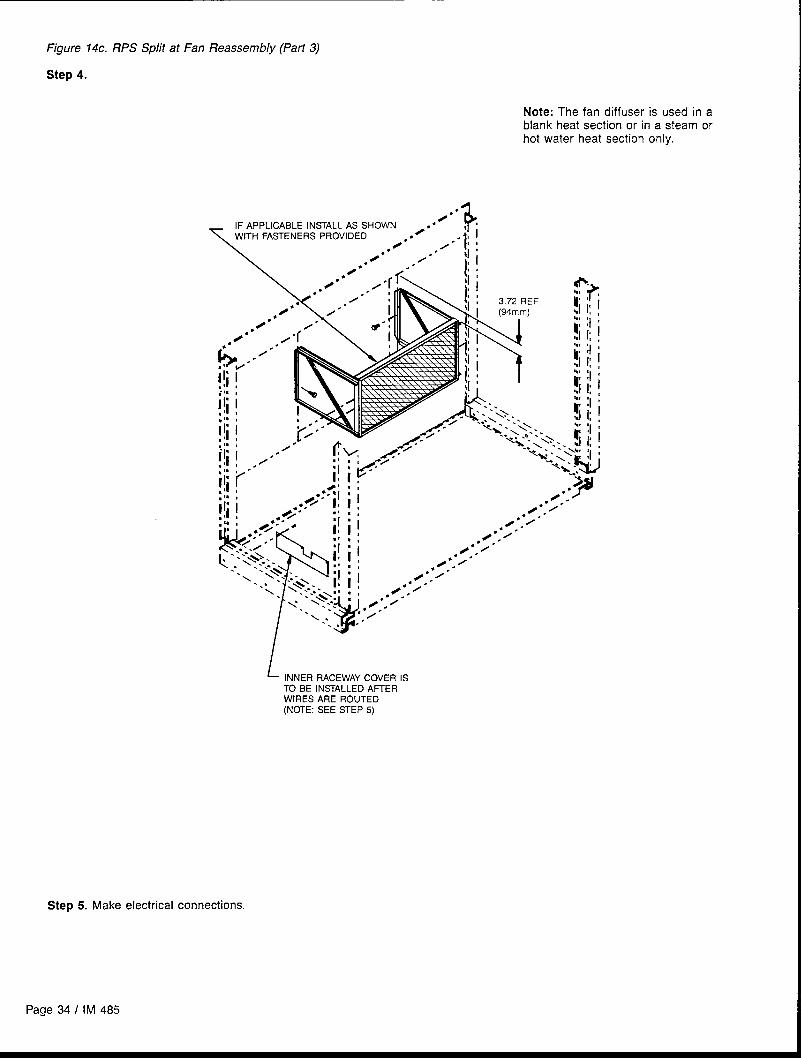
Figure 14c. RPS Split at Fan Reassembly (Part 3)
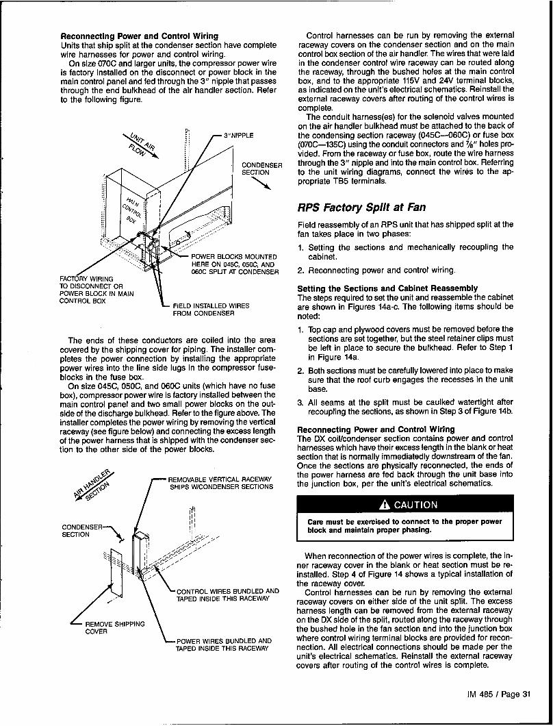
Step 4.
Note: The fan diffuser is used in ablank heat section or in a steam orhot water heat section only.
.
IF APPLICABLE INSTALL AS SHOWN z s ●
/“
\
+WITH FASTENERS PROVIDED ●4”* ./”” i:!
●R* -/” dhI
Page 34 I IM 485
L INNER RACEWAY COVER ISTO BE INSTALLED AFTERWIRES ARE ROUTED(NOTE: SEE STEP 5)
Step 5. Make electrical connections.

Installing Ductwork
I
On bottom-supply/bottom-return units, the installing contrac-tor should make an airtight connection by attaching field
\ fabricated duct collars to the bottom surface of either the roofcurb’s duct flange or the unit’s duct opening if a McQuay roofcurb is not used. Do not support the total weight of the duct-work from the unit or these duct flanges. Refer to Figure 15.
Units with optional back return, side discharge, or enddischarge (on RFS units) all have duct collars provided. Thedischarge duct collars on a side discharge unit are exposedby removing the plenum section access door and the doorgasketing.
Flexible connections should be used between the unit andductwork to avoid transmission of vibration from the unit tothe structure.
Ductwork should be designed per ASHRAE and SMACNArecommendations to minimize losses and sound transmission.
Figure 15. Installing Ductwork
UNIT DUCTOPENING
\
Nll
Where return air ducts are not required, it is recommendedthat a sound absorbing T or L section be connected to theunit return to reduce noise transmission to the occupiedspace.
Ductwork exposed to outdoor conditions must be built inaccordance with ASHRAE and SMACNA recommendationsand local building codes.
~
On units with side discharge, access to plenum mountedcomponents becomes difficult once ductwork is installed.
Installer must provide access m the ductwork for plenum
/
UNIT BASE
~ - ~ \
To
9.76”
I /
ii \ —IL I<<
FLEXIBLE ‘:CONNECTOR
$
DUCTWORK<~
Installing
\t
‘OUCT FLANGEIN ROOF CURB
Duct Static
For all VAV units, duct static pressure taps must be field in-stalled and connected to the pressure sensors in the unit. Sen-sor SPS1 is standard; additional sensor SPS2 is optional.These sensors are located at the bottom of the main controlpanel next to terminal block TB2 (see “Control Panel Loca-tions” in the “Unit Description” section of this manual).
The duct static pressure sensing tap must be carefullylocated and installed. Improper location or installation of thesensing tap will cause unsatisfactory operation of the entirevariable air volume system. Following are pressure tap loca-tion and installation recommendations. The installation mustcomply with local code requirements.
~ROOFCuRB
Pressure Sensor Taps
Fragile sensor fittings. May damage pressure sensor.
If tubing must be removed from a pressure sensor fitting, usecare. Do not wrench the tubing back and forth to remove orthe fitting may break off.
1. Install a tee fitting with a leak-tight removable cap in eachtube near the sensor. This will facilitate connecting amanometer or pressure gauge if testing is required.
IM 485 I Page 35
2.
3.
4.
5.
6.
Use different colored tubing for the duct pressure (Hi) andreference pressure (LO) taps, or tag the tubes.
Locate the duct pressure (Hi) tap near the end of a longduct to ensure that all terminal box take-offs along the runwill have adequate static pressure.
Locate the duct tap in a nonturbulent flow area of the duct.Keep it several duct diameters away from take-off points,bends, neckdowns, attenuators, vanes, or other irregulari-ties.
Use a static pressure tip (Dwyer A302 or equivalent) or thebare end of the plastic tubing for the duct tap. (If the ductis lined inside, use a static pressure tip device.)
Install the duct tap so that it senses only static pressure
Figure 16. Duct Static Pressure Tap Installation
TO SENSOR
TO SENSOR“LO” INPUT
RUBBERROMMET
TUBE CLA
PRESSUTUBING
TUBING EXTENDS ~THRU APPROX. 1A”
7.
8.
(not velocity pressure). If an L-shaped pressure tip device
is used, the point must face the airstream. If a bare tubeend is used, it must be smooth, square (not cut at anangle), and perpendicular to the airstream (see Figure 16).
Locate the reference pressure (LO) tap somewhere nearthe duct pressure tap within the building (see Figure 16).If the reference tap is not connected to the sensor, un-satisfactory operation will result,
Route the tubes between the curb and the supply duct,and feed them into the unit through the knockout in thebottom of the control panel (see Figure 17). Connect the
tubes to the appropriate 1/4 inch fittings on the sensors.Assure that the sensors do not support the weight of thetubing; use tube clamps or some other means.
Figure 17 Static Pressure Tubing Entrance Locafions
Installing Building Static Pressure Sensor Taps
If a unit has direct building static pressure control capability,static pressure taps must be field installed and connected topressure sensor SPS2 in the unit. This sensor is located atthe bottom of the main control panel next to terminal blockTB2 (see “Control Panel Locations” in the “Unit Description”section of this manual).
The two static pressure sensing taps must be carefullylocated and installed. Improper location or installation of thesensing taps will cause unsatisfactory operation. Followingare pressure tap location and installation recommendationsfor both building envelope and lab, or “space within a space,"pressure control applications. The installation must complywith local code requirements.
Fragile sensor fittings. May damage pressure sensor.
If tubing must be removed from a pressure sensor fitting, usecare. Do not wrench the tubing back and forth to remove orthe fitting may break off.
Building Pressurization Applications
1. Install a tee fitting with a leak-tight removable cap in eachtube near the sensor. This will facilitate connecting amanometer or pressure gauge if testing is required.
2.
3.
4.
5.
6.
7.
WIRINGCOVER
Locate the building pressure (Hi) tap in the area that re-quires the closest control. Typically, this is a ground levelfloor that has doors to the outside.
Locate the building tap so that it is not influenced by anysource of moving air (velocity pressure). These sourcesmay include air diffusers or outside doors.
Route the building tap tube between the curb and thesupply duct, and feed it into the unit through the knockoutin the bottom of the control panel (see Figure 17). Con-nect the tube to the 1/4 inch HI fitting on sensor SPS2.Assure that the sensor does not support the weight of thetubing; use tube clamps or some other means.
Locate the reference pressure (LO) tap on the roof. Keepit away from the condenser fans, walls, or anything elsethat may cause air turbulence. Mount it high enough abovethe roof so that it is not affected by snow, If the referencetap is not connected to the sensor, unsatisfactory opera-tion will result.
Use an outdoor static pressure tip (Dwyer A306 orequivalent) to minimize the adverse effects of wind. Placesome type of screen over the sensor to keep out insects.Loosely packed cotton works well.
Route the outdoor tap tube out of the main control pane!through a small field-cut opening in the edge of the con-trol wiring raceway cover (see Figure 17). Cut this “mousehole” in the vertical portion of the edge. Seal the penetra-
Page 36 I IM 485

tion to prevent water from entering. Connect the tube tothe 1/4 inch LO fitting on sensor SPS2.
Lab Pressurization Applications
1.
2.
3.
Install a tee fitting with a leak-tight removable cap in eachtube near the sensor. This will facilitate connecting amanometer or pressure gauge if testing is required.
Use different colored tubing for the controlled spacepressure (Hi) and reference pressure (LO) taps, or tag thetubes.
Regardless of whether the controlled space is positive ornegative with respect to its reference, locate the HI pres-sure tap in the controlled space. (The setpoint can be setbetween -0.2 and 0.2” W.C.)
4.
5.
6.
7.
Condensate Drain
Locate the reference pressure (LO) tap in the area sur-rounding the controlled space. If the reference tap is notconnected to the sensor, unsatisfactory operation willresult.
Locate both taps so that they are not influenced by anysource of moving air (velocity pressure). These sourcesmay include air diffusers or doors between the high andlow pressure areas.
Route the tap tubes between the curb and the supply duct,and feed them into the unit through the knockout in thebottom of the control panel (see Figure 17).
Connect the tubes to the appropriate 1/4 inch fittings onsensor SPS2. Assure that the sensor does not support theweight of the tubing; use tube clamps or some othermeans.
Connection
The unit is provided with a 1.50” male NPT condensate drain on the face of the evaporator coil, copper tubes near bothconnection: Refer to certified drawings for the exact location.The unit and drain pan must be level to within 0.25 inch sideto side and a P-trap must be installed for proper drainage.
On RPS and RFS units, the condensate drain is in a positivestatic pressure portion of the cabinet. In Figure 19, dimen-sion “A” should be a minimum of 8“ (203mm). As a conser-vative measure to prevent the cabinet static pressure fromblowing the water out of the trap and causing air leakage,dimension “A” should be two times the maximum staticpressure encountered in the coil section in inches W.C.
Drainage of condensate directly onto the roof may be ac-ceptable; refer to local code. It is recommended that a smalldrip pad of either stone, mortar, wood or metal be providedto protect the roof against possible damage.
If condensate is to be piped into the building drainagesystem, the drain line should be pitched away from the unitat a minimum of 1/8“ (3mm) per foot (305mm). The drain linemust penetrate the roof external to the unit. Refer to localcodes for additional requirements. Sealed drain lines requireventing to assure proper condensate flow.
Where the cooling coils have intermediate condensate pans
Figure 18. Condensate Drain Connection
STATIC PRESSURE ~ IN W.C.
I
DRAIN PAN
L
4“(102’=lJ2=’’”sT““(’o’mrnk’==u
1
\ /MINIMIZE THIS
DIMENSION
VIEW A
ends of the coil provide drainage to the main drain pan. Checkthat the copper tubes are in place and open before the unitis put into operation.
On units with staggered cooling coils, the upper drain pandrains into the lower coil drain pan through a copper tube nearthe center of the drain pan. Check that this tube is open beforeputting the unit into operation and as part of routine mainte-nance.
Because drain pans in any air conditioning unit will havesome moisture in them, algae, etc. will grow. Periodic clean-ing is necessary to prevent this build-up from plugging thedrain and causing the drain pan to overflow. Also, the drainpans should be kept clean to prevent the spread of disease.Cleaning should be performed by qualified personnel.
I Biological hazard. May cause disease.
Cleaning should be performedby qualified personnel. I
\VIEW “A”
// & COPPERTUBE
(ONE EACH END OF COIL)
IM 485 I Page 37
I

Unit Piping
Gas Piping
See the “installation” section of the gas fired furnace installa-tion manual, Bulletin No. IM 684 or 685.
Hot Water Coil Piping
Hot water coils are provided without valves for field piping,or piped with three-way valves and actuator motors. Note thatif the unit is equipped with an iron valve, connecting to a cop-per piping system will likely cause galvanic corrosion to oc-cur and the valve will not last. All coils have vents and drainsfactory installed.
Hot water coils are not normally recommended for use withentering air temperatures below 40F (40 C). No controlsystem can be depended on to be 100% safe against freeze-UP with water coils. Gycol solutions or brines are the onlyfreeze-safe media for operation of water coils at low enteringair temperature conditions.
The hot water heat section consists of two stacked coils,as shown in Figure 19. When no factory piping or valve is in-cluded, the coil connections are 2.12” ODM copper.
With the factory piping and valve package, the two coilsare piped in parallel and controlled through a single three-way valve. Field piping connections are the same NPT sizeas the valve.
Refer to the certified drawings for the recommended pip-ing entrance locations. All piping penetrations must be seal-ed to prevent air and water leakage.
Note: The valve actuator spring returns to a stem downposition upon power failure. This allows full flow through thecoil.
Coil freeze possible. May damage equipment.
Carefully read instructions for mixing antifreeze solution used.Some products will have higher freezing points in their naturalstate than when mixed with water. The freezing of coils is notthe responsibility of McQuay International.
Steam Coil Piping
Steam coils are provided without valves for field piping, orpiped with two-way valves and actuator motors.
The steam heat section consists of two stacked coils(pitched at 1/8” (3mm) per foot (305mm)), as shown in Figure20. When no factory piping or valve is included, the coil con-nections are 2.50” male NPT iron pipe.
With the factory piping and valve package, the two coil sup-plies are piped in parallel and controlled through a single two-way valve. The field supply connection is the same NPT sizeas the valve. Field return connections are made at each ofthe two stacked coils. See below for piping and steam traprecommendations.
Refer to the certified drawings for the recommended pip-ing entrance locations. All piping penetrations must be sealedto prevent air and water leakage.
Note: The valve actuator spring returns to a stem up posi-tion upon power failure. This allows full flow through the coil.
Piping Recommendations1. Be certain that adequate piping flexibility is provided.
Stresses resulting from expansion of closely coupled pip-ing and coil arrangement can cause serious damage.
2. Do not reduce pipe size at the coil return connection. Carry
Figure 19. l-lot Water Heat Section (Shown with FactoryValve and Piping)
SUPPLY
Figure 20. Steam Heat Section (Shown with Factory Valveand Piping)
3.
4.
5.
return connection size through the dirt pocket, making thereduction at the branch leading to the trap.
It is recommended that vacuum breakers be installed onall applications to prevent retaining condensate in the coil.Generally, the vacuum breaker is to be connected betweenthe coil inlet and the return main. However, if the systemhas a flooded return main, the vacuum breaker should beopen to the atmosphere and the trap design should allowventing of the large quantities of air.
Do not drain steam mains or take-offs through coils. Drainmains ahead of coils through a steam trap to the return line.
Do not attempt to lift condensate.
Page 38 I IM 485

6. Pitch all supply and return steam piping down a minimumof 1 inch (25mm) per 10 feet (3m) of direction of flow.
Steam Trap Recommendations1.
2.
3.
4.
5.
Size traps in accordance with manufacturers’ recommen-dations. Be certain that the required pressure differentialwill always be available. Do not undersize.
Float and thermostatic or bucket traps are recommendedfor low pressure steam. Use bucket traps on systems withon-off control only.
Locate traps at least 12 inches (305mm) below the coilreturn connection.
Always install strainers as close as possible to the inlet sideof the trap.
A single trap may generally be used for coils piped inparallel, but an individual trap for each coil is preferred.
Freeze ConditionsIf unit operation may occur when the air entering the steamcoil is below 35° F (20C), note the following recommendations:
1.
2.
3.
4.
5 PSI (34.5 kPa) steam must be supplied to coils at alltimes.
Modulating valves are not recommended. Control shouldbe by means of face and bypass dampers.
As additional protection against freeze-up, the trap shouldbe installed sufficiently far below coil to provide an ade-quate hydrostatic head to ensure removal of condensateduring an interruption on the steam pressure. Estimate 3feet (914mm) for each 1 PSI (7 kPa) of trap differentialrequired.
If the unit is to be operated in environments with possiblefreezing temperatures, an optional freezestat is recom-mended. Refer to “Freeze Protection” in the “Unit Options”section of this manual.
Cabinet Weatherproofing
This unit ships from the factory with fully gasketed access water runoff from overhangs or other structures.doors and cabinet caulking to assure weatherproof operation. Field assembled options, such as external piping vestibulesAfter the unit has been set in place, all door gaskets should or split units, are to be recaulked per the installation instruc-be inspected for shipping damage and replaced if necessary. tions provided with the option.
It is recommended the unit be protected from overhead
IM 485 I Page 39

Electrical Installation
Field Power Wiring
Wiring must comply with all applicable codes and ordinances.The warranty is voided if wiring is not in accordance with thesespecifications. An open fuse indicates a short, ground, oroverload. Before replacing a fuse or restarting a compressoror fan motor, the trouble must be found and corrected.
According to the National Electrical Code, a disconnectingmeans shall be located within sight of and readily accessiblefrom the air conditioning equipment. The unit may be orderedwith an optional factory mounted disconnect switch. Thisswitch is not fused. Power leads must be overcurrent protectedat the point of distribution. The maximum allowable overcur-rent protection is shown on the unit nameplate.
RPS and RFS Units
Hazardous voltage. May cause severe injury or death.
Disconnect electric power before servicing equipment. Morethan one disconnect may be required to de-energize the unit.
If the unit has a factory mounted disconnect switch, the switchmust generally be turned off to open the main control paneldoor. However, the door can be opened without disconnect-ing power by turning the screw at the bottom of disconnectswitch clockwise while pulling the door open. If this is done.however, caution must be used since power is not removedfrom the unit or the controller.
RPS and RFS units maybe ordered with internal power wir-ing for either single or multiple point power connections. Ifsingle point power is ordered, a single power block or an op-tional disconnect switch is located within the main controlpanel*: Field power leads are brought into the unit through3-inch knockouts in the bottom of the main control panel. Referto Figure 21A.
Units ordered with multiple point power connections are pro-vided with nonfused, factory mounted disconnect switches.Several multiple point power options are available, as shownin Table 7.
* 208,230V units with 160 kw or larger electric heat requiretwo power connections.
Note: Refer to certified drawings for dimensions to wire entry points.
Figure 21A. RPS and RFS Power Wiring Connections Figure 21B. Optional Side Power Wiring Entrance
FAN SECTION
OL
LE
FOR POWER WIRE FOR 115V SERVICE(QIY. 3 IN MAIN RECEPTACLE (QTY 2)CONTROL PANEL;QIY 3 IN ELECTRICALHEAT CONTROL PANEL)
N:%/4 !/\
Y (76mm)
C%40[,MAX. DIA. :
\
,.. - \,-..~-.. - ..eo-.>
;.,...
....~.:::q
,EMovE~”’-;’.,:&.:&
m ..-LIFTING BRACKET w
(IF LOCATED HERE)BEFORE DRILLING HOLE
The preferred entrance for power cables is through the bot-tom knockouts provided on the unit. If side entrance is theonly option, a drilling location is provided. The drilling dimen-sions must be followed exactly to prevent damage to the con-trol panel. The dimensions provided are the only possiblepoint of side entrance for the power cables.
Page 40 I IM 485

v
I
Table Z Multiple Point Power Connection Options
~ Number of Electrical Clrcults Disconnect Daslgnatlon Load Location (See Figure 21)
2DS2 Supply & return fan motors Main control panel
DS1 Balance of unit Msin control panel
2DS3 Electric heat Electric heat control panel
DS1 Balance of unit Main control panel
DS3 Electric heat Electric heat control panel
3DS2 Supply & return fan motors, controls Main control panel
DSI Balance of unit Main control panel
RCS Units
The RCS unit is provided with its own single point power con-nection. Field power wiring is connected to a power block oroptional factory mounted nonfused disconnect switch locatedin the condenser control panel. Power leads enter the lowerleft rear corner of the condenser control panel through theconduit hubs shipped with the unit. Refer to Figure 22.
Figure 22. RCS Power Wiring Connections
1- TERMINAL BLOCK TB1
%“ KNocKOUT FOR WIRE ENTRYFOR 115VSERVICE
(FIELD lU CUT LARGER HOLESRECEPTACLECIRCUIT
AS REQUIREDFOR POWERWIRE)
FanTrol
FanTrot is provided onpressure control which
all units and is a method of headautomatically cycles the condenser
fans in response to condenser pressure and ambient airtemperature. This feature maintains head pressure and allowsthe unit to run at low ambient air temperatures.
All RPS/RCS units have two independent refrigerant cir-cuits with one to four condenser fans being controlled in-dependently by the condensing pressure or ambient airtemperature of each circuit. An additional condenser fan ineach circuit is not cycled by FanTrol but is reserved for op-tional SpeedTrol control. See sections below for sequence ofoperation for condenser fans with FanTrol.
All Units
The minimum circuit ampacity (wire sizing amps) is shownon the unit nameplate. Refer to Table 8 for the recommendednumber of power wires.
Copper wire is required for all conductors. Size wires in ac-cordance with the ampacity tables in Article 310 of the Na-tional Electrical Code. If long wires are required, it may benecessary to increase the wire size to prevent excessivevoltage drop. Wires should be sized for a maximum of 3%voltage drop. Supply voltage must not vary by more than IO%of nameplate. Phase voltage imbalance must not exceed 2%.(Calculate the average voltage of the three legs. The leg withvoltage deviating the farthest from the average value mustnot be more than 2% away.) Contact local power companyfor correction of improper voltage or phase imbalance.
Improper line voltage or excessive phase imbalance con-stitute product abuse. May cause severe damage to the
Assure proper line voltage and phase balance.
Aground lug is provided in the control panel for each powerconduit. Size grounding conductor in accordance with Table250-95 of the National Electrical Code.
In compliance with the National Electrical Code, an elec-trically isolated 115V circuit is provided in the unit to supplythe factory mounted service receptacle outlet and optional unitlights. This circuit is powered by a field connected 15A, 115Vpower supply. Leads are brought into the RPS and RFS unitsthrough a 7/8” knockout in the bottom of the main controlpanel, near the power wire entry point. On RCS units, the 115Vleads are brought into the lower left rear of the condensercontrol panel.
Note: The National Electrical Code requires that this 115Vcircuit be protected by a ground fault circuit interrupter (GFI)device (field supplied).
All protecbvedeadfront panels must be reinstalled and secured
IM 485 I Page 41
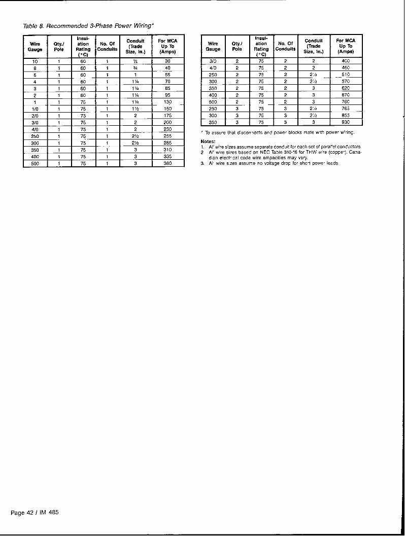
Table 8. Recommended 3-Phase Power Wiring*
wireGauge
108
6
4
3
2
1
1/0
2/0
3/0
4/0
250
300
350
400
500
lnaul-Qty.1 etion No. Of
Conduit For MCA
Pole Rating Conduits(Trade Up To
(“c) Size, In.) (Amps)
1 60 1 V2 30
1 60 1 % 40
1 60 1 1 55
1 60 1 f 1~ 70
1 60 1 11~ 85
1 60 1 11/4 95
1 75 1 11/4 130
1 75 1 11/2 150
1 75 1 2 175
1 75 1 2 200
1 75 1 2 230
1 75 1 21/2 255
lnsul-Wira fny.1 ation No. Of
Conduit For MCA
Gauge Pole Rating Conduits(Trade Up To
(“c) Siie, In.) (Amps)
3/0 2 75 2 2 400
4/0 2 75 2 2 460
250 2 75 2 21/2 510
300 2 75 2 2M 570
350 2 75 2 3 620
400 2 75 2 3 670
500 2 75 2 3 760
250 3 75 3 2 V2 765
300 3 75 3 2Y2 855
350 I 3 I 75 I 3 I 3 I 930 1
‘ To assure that disconnects and power blocks mate with power wiring
Notes:1.All wire sizes assume separate conduit for each set of parallel conductors2, All wire sizes based on NEC Table 310-16 for THW wire (copper). Cana-
dian electrical code wire ampacities may vary3. All wire sizes assume no voltage drop for short power leads.
Page 42 I IM 485
Field Control Wiring
RoofPak applied rooftop units are available with several con-trol arrangements which may require low voltage field wiring.Detailed descriptions of the various field control wiring options
I and requirements are included in the “Field Wiring” sectionof Bulletin No. IM 483, “MicroTech Applied Rooftop Unit Con-troller? Refer to the unit wiring diagrams for additional installa-tion information.
Wiring must comply with all applicable codes and or-dinances. The warranty is voided if wiring is not in accordancewith these specifications.
Electric shock hazard. Can cause severe injury or death.
Connect only low voltage NEC Class II circuits to terminalblocks TB2 and TB7.
Reinstall and secure all protective deadfront panels when thewiring installation is complete.
Figure 23. RPS and RFS Field Control Wiring Connections
RPS and RFS Units
Most field control wiring connections are made at terminalblock TB2, which is located in the main control panel. Somecontrol options require field wiring connections to terminalblock TB7, which is also located in the main control panel.Refer to Figure 23 and see “Main Control Panel” in the “Con-trol Panel Locations” section of this manual. Two 7/8”knockouts are provided for wire entry.
CONTROL WIRING RACEWAYCOVER (REMOVE FOR ACCESSTO HARNESS FROM MAIN CONTROLBOX TO UNIT MOUNTEO CONTROLDEVICES)
Note: If a single conduit containing 24V and 115V wiringis run above the roofline between the RFS and RCS units,the 24V wiring must be installed as an NEC Class I wiringsystem.
RFSIRCS Units
The RCS unit receives 115V and 24V control circuit powerand a number of control signals from the RFS unit. Two 7/8”knockouts are provided in the right side of the RCS controlbox. The 115V wiring is connected to terminal block TB3through the upper knockout. The 24V wiring is connected toterminal block TB2 through the lower knockout.
Interconnecting wiring enters the RFS unit through 7/8”knockouts in the bottom of the main control panel. The 115Vwiring is connected to TB5 and the 24V wiring is connectedto terminal block TB7. Refer to Figure 24.
A 7/8” knockout is also available in the end of the unit baseas shown in Figure 24.
Figure 24. RFSIRCS Interconnecting Control Wiring
RCS UNITMAIN RFS UNIT (VIEWING CONTROL BOX END)
TB7(24V
IM 485 I Page 43
Readying Unit for Operation
I Moving machinery hazard. May cause severe injury or death.
Disconnect power and lock “off” before servicing equipment. More than one disconnect may be required to de-energize unit.
Spring Isolated Fans
Release of Spring Mounts
The optional spring-mounted supply and return fans arelocked down for shipment. Hold-down fasteners are locatedat each spring mount. These fasteners must be removedbefore operating the fans. Figure 25 shows a typical springmount. Note that the %“ hold-down bolt securing the fan baseto the unit cross channel must be removed, as well as all 1/4"screws directly above the spring mount.
in some unit arrangements, one of the 3/8“ hold-down boltslies below the motor base. The bolt can be reached with a9/16“ socket and must be removed.
After removing the hold-down fasteners, the fan assemblyshould be rocked by hand to check for freedom of movement.
Adjustment of Spring Mounts
During operation, all fans should ride level, with the bottomof the fan base approximately 3/8“ (lOmm) above the top ofthe unit’s cross channel. Unhoused single-width “plug” fanswill also ride at this level when at rest.
~
Moving machinery hazard. Can cause severe damage to
The fans must be started for the first time in accordance withthe “Check, Test, and Start Procedures” section of this manual.If this is not done, severe fan damage can occur.
When not operating, housed double-width fans will ride
lower at the discharge end of the fan base than at the motorend. When the fan is operating against a static pressure, itshould run level. If not, level the assembly as follows (referto Figure 26):
1. Loosen the 15/16” jam nut above the fan base.
Figure 25. Spring Mount Hold-Down Fasteners
D-DOWNREMOVERUNNING
Figure 26. Fan Spring Mount Adjustment
LEVELING SCREW ~
SPRING It
MOUNT \FAN
ASSEMBLYWISE
CHANNEL*.CROSS
{ ) WITH FANRUNFWG1
“This ~~” (lOmm) can be affected by thrust restraints that are grossly Oul Ofadjustment. This dimension must be rechecked after thrust restraints areadjusted.
2. Using a large, straight blade screwdriver, turn the 5/8“ level-ing screw clockwise to lower the fan base, counterclock-wise to raise the fan base.
3. When properly adjusted, retighten the jam nut.
Page 44/ [M 485
Adjustment of Supply Fan Thrust Restraints
Thrust restraints are provided when housed double-width fansare mounted on springs. After the spring mounts have beenadjusted for level operation when the fan is running, the thrustrestraints should be checked. With the fan off, the adjustment
Figure 27. Thrust Restraint Adjustment
REFER TODETAIL “A”
nuts should beset so the spring is slightly compressed againstthe angle bolted to the fan housing frame. Refer to Figure27. When the fan is turned on, the fan will move back to alevel position and the thrust restraint springs will compress.
/
NUT “B”
~ SPRING CUP
Restraint Adjustment fwith Fan Off)en jsm nuts “A”.nut “c” until srxin~ curI and washer conta~ thrust
111.JH\THRUST RESTRAINT ANGLE
~ FAN HOUSING FRAMEI
DETAIL “A”
3. Turn nut “B” until sprin~ is compressed by two turns of4. Tighten jam nuts “A”.
Seismic
Spring mounted supply air and return air fans may be orderedwith factory installed seismic restraints. The system consistsof four snubbers, one located next to each spring isolator.These snubbers will allow free movement of the fanassemblies during normal operation because normal opera-tion will not cause fan movements that exceed .25 inch (6mm).However they will restrain the fan assembly and limit move-ment to .25 inch (6mm) in any direction if an abnormal con-dition were to occur.
The position the fan will assume during normal operationwill be determined by actual job site CFM and static pressure.Therefore, for proper operation, the seismic restraints mustbe field adjusted as part of the normal system “Check, Test,and Start” procedure. When the fan is operating in a normalmanner there should be no contact between the snubberrestrainer angle and the snubber neoprene bumper. Howeverin a “seismic Event” the snubber will limit movement of thespring mounted fan assembly to .25 inch (6mm) in any direc-tion, thereby preventing the fan from being tossed about anddamaged, or causing damage.
When a seismic restraint is properly adjusted and the fanis operating normally, the neoprene center bumper will becentered within the 2 inch (51mm) diameter hole in therestrainer angle, and the restrainer angle will be centered ver-tically between the flanges of the neoprene center bumper.This results in .25 inch (6mm) clearance in all directions. Whenthe fan is turned off the restrainer angle may come to reston the neoprene center bumper.
Restraints
restraint angle.nut “B”.
The seismic restraint is adjustable in all directions. Verticalslots in the restrainer angle and horizontal slots in the blowerbase it is bolted to allow the restrainer angle to be adjustedup and down and back and forth. The neoprene centerbumper is mounted on a slotted hole allowing its adjustmentin and out.
Removing the neoprene center bumper bolt allows removal,disassembly, and replacement of the neoprene components.
Cross Section of Seismic Restraint
In
Snubber Neoprene Bumper *’Y
.25” (6mm) Ga(Fan Running)
T.
Snubber....... ..
...... ... ...\ ., ?..///..~>.NeopreneBumper
w:
lfvl 485 I Page 45

Spring Isolated Compressors
Units that have been ordered with optional compressor mount- Figure 28. Compressor Mounting Springsing springs must have the rigid shipping spacers removedbefore operating the units. Refer to Figure 28.
Before operating the unit, remove and discard the ship-ping spacers (1),and install the neoprene spacers (2). Removethe top mounting nuts (3). Install one neoprene spacer on each ,“ (2mm)
of the four mounting bolts.Replace the mounting nuts, leaving 1/16” (2mm) space bet-
ween the mounting nut and the neoprene spacer.
Refrigeration Service Valves
The unit is shipped with all refrigeration service valves closed. Liquid Valve — One per refrigeration circuit, located at endRPS and RCS units have the following: of condensing section opposite the condenser control box.
Page 46 I IM 485
Suction Valve — One per compressor, located on compres-sor.
RFS units do not ship with service valves installed.Before attempting to start the compressors, all refrigera-
Discharge Valve — One per compressor, located on compres- sion service valves should be fully opened and backseated.ser.

Sequences of OperationThe following sequences of operation are for a tvpical “C” from those described here. Refer to the wiring diagrams supvintage applied rooftop unit that is equipped with-an econo- plied with the unit for exact information. - - “mizer, part winding fan start, a return air fan, an external time For detailed description of operation information relating toclock, and a Remote Monitor Panel. These sequences the MicroTech controller’s software, refer to the appropriatedescribe the ladder wiring diagram logic in detail; refer to the operation manual (see Table 1). These manuals describe theschematics in the “Wiring Diagrams” section as you read various setpoints, parameters, operating states, and controlthem. Note that your unit’s sequences of operation may vary algorithms that affect rooftop unit operation.
Power-up
When primary power is connected to the unit, 115VAC poweris fed through control circuit transformer TI and control cir-cuit fuse FI (line 200) to compressor crankcase heaters HTR-1and HTR-2 (lines 805 and 855).
When system switch S1 (line 205) is closed, low voltagetransformers T2 (line 203) and T3 (line 208) are energized,and 115VAC power is supplied to the following:. economizer actuator ACT3 (line 336)● suppIy fan vane actuator ACT1 (line 340, VAV only). return fan vane actuator ACT2 (line 346, VAV only). compressor circuit switches CSI and CS2 (lines 807 and
857)● unit manual pumpdown switch PS3 (line 328)
Transformer T3 supplies 18VAC center-tapped power to thepower in terminals 1,2 & 3 on the micro control board MCB1(line 210). By way of terminal TB6-47 (lines 207 and 251),transformer T2 supplies 24VAC power to the following:● static pressure sensor SPS1 (line 230, VAV only). static pressure sensors SPS2, SPS5, SPS6 (lines 232-236). enthalpy sensor OAE (line 254)● external time clock contacts (line 256)
●
●
●
●
●
●
●
●
●
●
external exhaust fan status contacts (line 257)Remote Monitor Panel on-off switch (line 259)Remote Monitor Panel heat-auto-cool switch (lines 259 and262)airflow interlock switch PC7 (line 263)dirty filter switches PC5 and PC6 (lines 264 and 265)compressor safety relays R5 and R6 (lines 266-270)duct high limit switch DHL (line 272, VAV and CAV-DTC only)gas furnace alarm relay R24 (line 275)freezestat switch FS1 (line 278)smoke detectors SDI and SD2 (line 281)
When the fan switch on the Remote Monitor Panel is in the“off” position, field wiring terminals 105 and 106 (lines 259and 262) are de-energized. These respective terminals areconnected to the cool enable digital input D3 (terminal DHI-3)and the heat enable digital input D4 (terminal DH1-4) on theADI board. If terminals DH1-3 and DHI-4 are both de-energized, the MicroTech controller disables fan operationbecause it assumes the fan switch is off. If either terminalDHI-3 or DH1-4 is energized, the MicroTech controller enablesfan operation because it assumes the fan switch is on.
Fan Operation
When the supply and return fans are commanded to start by theMicroprocessor Control Board (MCB1), the unit enters the Star-tup Initial operating state. As a result, a 3-minute timer is set,solid-state output relay 0BA15 energizes, relay R26 energizes(Iine328), and the occupied output contacts close (line 395). OnVAV units, output relays OBA1Oand 0BA12 energize (line 343),causing the supply and return fan inlet vanes to open. When thevanes open to their minimum positions, OBA1Oand OBA12 arede-energized, causing the inlet vanes to hold.
After the 3-minute timer expires, the unit enters the Recir-culate operating state. As a result, output relay OBA13 energizes(line 301), causing supply fan contractors M9 and M1O toenergize. Time delay relay TD9 causes part winding start con-tactor M9 to energize slightly after MIO. (For more informationon the part winding start option, seethe “Unit Options” sectionof this manual.) Four seconds after OBA13 is energized, outputrelay 0BA14 energizes (line 303), causing return fan contractorsM19 and M20 to energize. Time delay relay TD19 causes partwinding start contactor M19 to energize slightly after M20.Overload relays 0L9, OL1O, 0L19, and 0L20 (line 301) protectthe fans from excessive current draw. If either the supply orreturn fan is drawing excessive current, one of the relays willopen its contacts and cause both fans to stop.
Within 30 seconds after the fans start, the controller ex-
pects airflow switch PC7 (line 263) to close and thus energizedigital input D8 (terminal DH1-8) on the ADI board. (If DH2-8does not energize, the controller will assume the fans did notstart. It will then shut down the unit and generate an alarm.)
During the Recirculate operating state, the outside airdamper is held closed. The controller does this by energiz-ing output relay OBA7 (line 338). On VAV units, output relay0BA6, the VAV box output, is also energized (line 395) dur-ing the Recirculate state.
On VAV units, the supply fan vanes (ACTI) are modulatedto maintain the duct static pressure setpoint. When energized,output relay OBA1O opens them, and 0BA9 closes them (line343). On VAV units or CAV units equipped with return fan in-let vanes, the return fan vanes (ACT2) are modulated to main-tain an acceptable building static pressure. When energized,output relay 0BA12 opens them, and OBA1l closes them (line343). (Switch S6 on line 342 is provided for supply/return fanairflow balancing which is part of the unit check, test, andstart procedure.)
Note: The “Typical Actuator Control Circuit” and “TypicalSupply/Return Fan Control Circuit” schematics show optionsthat are not discussed here. These options are isolationdampers (ACT5 and ACT6), motorized relief dampers (ACTIOand ACT1l), and modulating hot water or steam heat (VM1).
I
IM 485 J Page 47

Economizer Operation
When the outdoor air is suitable for free cooling, the switchin enthalpy sensor OAE is in position “3” (line 254), and thusdigital input DO(terminal DHI-0) on the ADI board is energiz-ed. When DH1-1 is energized, the economizer is enabled. Ifcooling is required, the economizer dampers (ACT3) aremodulated to maintain the discharge air temperature setpoint.When energized, output relay 0BA8 opens the outdoor airdampers, and 0BA7 closes them (line 338). If the outdoor air
dampers are wide open and more cooling is required, thedampers will hold their positions and mechanical cooling will
be activated (see below).
When the outdoor air is not suitable for free cooling. the switchin enthalpy sensor OAE is in position “l”, and thus digital inputDO (terminal DHI-0) on the ADI board is de-energized. WhenDH1-O is de-energized, the economizer is disabled and thedampers are then held at their minimum position.
Mechanical Cooling Operation
%“ IVO 24VCONTROL
NCE~ 2.30w(58rm).LPlI .
CONDENSER CONTROLPANEL RIGHT
,.07” (78mm)/ (21I.mm) 13.50s
%-IVO TO CIITMAIN POWER ENTRY
3
f’- -w(343rnm)
2-Compressor Unit
Refer to the “Typical Condenser Control Circuit (2-Compres-sor/4-Stage)” schematic in the following section, “WringDiagrams;’ as you read this sequence of operation. In thefollowing description, compressor #1 is lead.
When system switch S1 and compressor control switchesCSI and CS2 are closed, 115VAC power is supplied to relaysR5 (line 807) and R6 (line 857) via the normally closed con-tacts of(1) the high pressure safety relays, R1 and R2; (2) theoil pressure safety controls, OP1 and 0P2; and (3) the com-pressor motor protectors, MPI and MP2. As a result, relaysR5 and R6 energize and their normally open contacts close(lines 812, 842, 862, and 892), enabling operation of theirrespective compressors, #1 and #2. (See “CompressorSafeties” below for more information.)
Switches S1, CS1, and CS2 also supply power to com-pressor lockout time delay relays TD1 and TD2 (lines 811 and861), which then close their contacts after 5 minutes. (See“Compressor Timer Lockout” below for more information onthese relays.) When the time delay relay contacts close, relaysR9 (line 811) and R1O (line 861) energize and their normallyopen contacts close (lines 842 and 892), further enabling com-pressor operation. When manual pumpdown switches PS1,PS2, and PS3 are closed, both compressors are fully enabledand ready to start if commanded to by the MicroTech controller.
If cooling is enabled (digital input D3 (terminal DHI-3) onthe ADI board energized) and mechanical cooling is required,the MCB1 controller will energize solid-state output relaysOBA1 and OBA4 (lines 842 and 845). The closed OBAI con-tacts energize and open liquid line solenoid valve SV1 (line841), allowing refrigerant to flow into the evaporator coil. Asthe refrigerant evaporates, the suction pressure increases until
low pressure switch LPI closes (line 812). When LPI closes.contractors Ml and Mll energize (lines 813 and 816) and com-pressor #l and condenser fan #11 start. (The above descrip-tion applies to units without the low ambient start option, Fora description of low ambient start, see the “Unit Options” sec-tion of this manual,) FanTrol control is allowed to cycle con-denser fans 12, 13, and 14 to maintain the proper refrigeranthead pressure. Pressure control PC12, which senses headpressure, controls contactor M12 (line 817), which cycles con-denser fan 12. Temperature controls TC13 and TC14, whichsense ambient temperature, control contractors M13 and M14(lines 818 and 819), which cycle condenser fans 13 and 14,The closed 0BA4 contacts energize unloader U1 on com-pressor #1 (line 845), reducing the capacity of (unloading) thecompressor. This is stage 1.
If more cooling is required, MCB1 will also energize out-put relays 0BA2 and OBA5 (lines 892 and 895). The resultis that compressor #2 and its unloader are energized. Thisis stage 2. The sequence of operation for compressor *2 ssimilar to the above description for compressor #l.
If more cooling is required, MCBI will de-energize outputrelay OBA4. The open 0BA4 contacts de-energize unloaderU1 on compressor #1, fully-loading the compressor. This isstage 3.
If more cooling is required, MCB1 will de-energize outputrelay OBA5. The open OBA5 contacts de-energize unloaderU1 on compressor #2, fully loading the compressor. This isstage 4.
When the cooling demand is satisfied, MCB1 stages downthe compressors in the reverse order. When both compressorare running unloaded (stage 2) and less cooling is required,MCB1 stages down by de-energizing 0BA2 and 0BA5. Theopen OBA2 contacts de-energize and close liquid line solenoidvalve SV2 (line 891). As a result, compressor #2 pumps downrefrigeration circuit #2 until the suction pressure drops lowenough to open low pressure control LP2 (line 862). WhenLP2 opens, compressor #2 and its associated condenser fansare shut down.
When mechanical cooling is no longer necessary, MCB1de-energizes OBA1 and 0BA4. The open OBA1 contacts re-energize and close liquid line solenoid valve SV1. Wth SV1closed, refrigeration circuit #l pumps down until low pressureswitch LPI opens.
Compressor SafetiesIf an oil pressure switch or compressor motor protector trips,the compressor will be disabled by relay R5 or R6 (line 807,812, 857 and 862).
If high pressure switch HP1 trips (line 809), compressor #lwill be disabled and locked out by relay RI (lines 807-809)in conjunction with relay R5. If high pressure switch HP2 trips(line 859), compressor #2 will be disabled and locked out byrelay R2 (lines 857-859) in conjunction with relay R6.
Page 48 I IM 485
4-Compressor Unit
Refer to “Typical Condenser Control Circuit (4-Compres-sor/8-Stage~i schematic in the following section, “WiringDiagrams,” as you read this sequence of operation. Note thatrefrigeration circuit #1 includes compressors #1 and #3, whichare piped in parallel, and refrigeration circuit #2 includes com-pressors #2 and #4, which are also piped in parallel. In thefollowing description, compressor #1 is lead.
When system switch S1 and compressor control switchesCS1 and CS2 are closed, I15VAC power is supplied to relaysR5 (line 807), R6 (line 857), R7 (line 835), and R8 (line 885)via the normally closed contacts of(1) the high pressure safetyrelays, RI and R2; (2) the oil pressure safety controls,OP1-0P4; and (3) the compressor motor protectors, MP1-MP4.As a result, relays R5 through R8 energize and their normal-ly open contacts close (lines 812,816,842,862,866, 892,818,831, 844, 868, 881, and 891), enabling operation of theirrespective compressors, #1 through #4. In addition, the nor-mally closed contacts of relays R5 and R6 open (lines 819and 869), preventing operation of compressors #3 and #4 untilthe controller commands it. (See “Compressor Safeties”below for more information.)
Switches S1, CS1, and CS2 also supply power to com-pressor lockout time delay relays TDI and TD2 (lines 811 and861), which then close their contacts after 5 minutes. (See“Compressor Timer Lockout” below for more information onthese relays.) When the time delay relay contacts close, relaysR9 (line 811) and R1O (line 861) energize and their normallyopen contacts close (lines 842 and 892), further enabling com-pressor operation. When manual pumpdown switches PSI,PS2, and PS3 are closed, all compressors are fully enabledand ready to start if commanded to by the MicroTech controller.
If cooling is enabled (digital input D3 (terminal DHI-3) onthe ADI board energized) and mechanical cooling is required,the MCB1 controller will energize solid-state output relaysOBBO and OBB2 (lines 842 and 845). The closed OBBO con-tacts energize and open liquid line solenoid valve SV1 (line841), allowing refrigerant to flow into the evaporator coil. Asthe refrigerant evaporates, the suction pressure increases untillow pressure switch LPI closes (line 812). When LPI closes,contractors Ml and Mll energize (lines 813 and 816) and com-pressor #1 and condenser fan #11 start. (The above descrip-tion applies to units without the low ambient start option. Fora description of low ambient start, see the “Unit Options” sec-tion of this manual.) FanTrol control is allowed to cycle con-denser fans 12, 13, and 14 to maintain the proper refrigeranthead pressure. Pressure control PC12, which senses headpressure, controls contactor M12 (line 817), which cycles con-denser fan 12. Temperature controls TC13 and TC14, whichsense ambient temperature, control contractors M13 and M14(lines 818 and 819), which cycle condenser fans 13 and 14.The closed 0BB2 contacts energize unloader U1 on com-pressor #1 (line 845), reducing the capacity of (unloading) thecompressor. This is stage 1.
If more cooling is required, MCBI will also energize out-put relays OBB1 and 0BB3 (lines 892 and 895). The resultis that compressor #2 and its unloader are energized. Thisis stage 2. The sequence of operation for compressor #2 issimilar to the above description for compressor #1.
If more cooling is required, MCB1 will de-energize outputrelay 0BB2. The open 0BB2 contacts de-energize unloaderUI on compressor #1, fully loading the compressor. This isstage 3.
If more cooling is required, MCBI will de-energize outputrelay 0BB3. The open 0BB3 contacts de-energize unloaderU1 on compressor #2, fully loading the compressor. This isstage 4.
If more cooling is required, MCB1 will energize output relaysOBB2 and OBB4 (line 831). The closed 0BB2 contacts re-energize unloader U1 on compressor #1, again unloading thecompressor. When 0BB4 closes, contactor M3 energizes (line
832) and compressor #3 starts and runs at full capacity. (Thenet result is an increase in capacity.) This is stage 5.
If more cooling is required, MCB1 will energize output relays0BB3 and 0BB5 (line 881). The closed 0BB3 contacts re-energize unloader U1 on compressor #2, again unloading thecompressor. When 0BB5 closes, contactor M4 energizes (line882) and compressor #4 starts and runs at full capacity. Thisis stage 6.
If more cooling is required, MCB1 will again de-energizeoutput relay OBB2, de-energizing unloader U1 on compressor#1 and fully loading the compressor. This is stage 7.
If more cooling is required, MCBI will again de-energizeoutput relay 0BB3, de-energizing unloader U1 on compressor#2 and fully loading the compressor. This is stage 8.
When the cooling demand is satisfied, MCBI stages downthe compressors in the reverse order. When compressors #1and #2 are running unloaded (stage 2) and less cooling isrequired, MCBI stages down by de-energizing OBB1 andOBB3. The open OBB1 contacts de-energize and close liquidline solenoid valve SV2 (line 891). As a result, compressor #2pumps down refrigeration circuit #2 until the suction pressuredrops low enough to open low pressure control LP2 (line 862).When LP2 opens, compressor #2 and its associated con-
denser fans are shut down.When mechanical cooling is no longer necessary, MCB1
de-energizes OBBO and 0BB2. The open OBBO contacts re-energize and close liquid line solenoid valve SV1. With SV1closed, refrigeration circuit #1 pumps down until low pressureswitch LPI opens.
Compressor SafetiesIf an oil pressure switch or compressor motor protector trips,the compressor will be disabled by relay R5, R6, R7, or R8.If the failed compressor is either #1 or #2, compressor #3 or#4 will automatically take its place in the staging sequence.For example, if compressor #1 is not functional because MP1has tripped, relay R5 will de-energize and its normally closedcontacts will close (line 819). As a result, contactor M3 ener-gizes when LP1 closes and turn compressor #3 will beenergized instead of #1 for the first stage of cooling. The nor-mally open R5 contacts in line 812 prevent contactor Ml fromenergizing. Since R7 is energized, its normally open contactsin line 818 are closed and thus the condenser fan circuits re-main enabled.
If high pressure switch HP1 or HP3 trips (lines 809 and 810),compressors #1 and #3 will be disabled and locked out byrelay RI (lines 807-809 and 835) in conjunction with relaysR5 and R7. If high pressure switch HP2 or HP4 trips (lines859 and 860), compressors #2 and #4 will be disabled andlocked out by relay R2 (lines 857-859 and 885) in conjunctionwith relays R6 and R8.
Compressor Timer Lockout
Time delay relays TDI and TD2 prevent rapid cycling of thecompressors. Whenever compressor #1 or #2 cycles off, itsassociated time delay relay resets and starts a 5-minute delaytimer. The timer must expire before the liquid line solenoidvalve and compressor contactor will be allowed to energizeagain. Following is a sequence of operation for the timerlockout circuit. Refer to Figure 29. Assume that switches S1,CSI, and PS1 are closed.
1.
2.
After pumpdown, low pressure switch LPI opens, de-energizing compressor contactor Ml.
The contactor Ml auxiliarv (MI-AUX) contacts open. de-energizing relay R9 and starting the 5-minute timer in timedelay relay TD1. The TD1 contacts remain open during thedelay period. Because the M1-AUX and TD1 contacts arenow open, contactor Ml and thus compressor #1 are fullydisabled.
IM 485 I Page 49

3.
4.
5.
The relay R9 contacts open, disabling liquid line solenoidvalve SVI. Even if the MicroTech controller closes theOBBO contacts, the compressor cannot start because thesolenoid valve cannot open.
When the 5-minute timer expires, the TDI contacts close,reenergizing relay R9. As a result, the liquid line solenoidvalve and the compressor contactor circuit are again en-abled.
When LPI closes again. contactor Ml energizes, the.,.compressor starts, and Ml -AUX closes. Because there isnow no voltage across TDI, its contacts open.
Note: If a compressor periodically repeats the pumpdowncycle when it is supposed to be off, there is an internal leak ateither the liquid line solenoid valve or the valves in thecompressor. Frost on the compressor head or the downstreamside of the solenoid valve indicate the location of the leak. If acompressor recycles more than once every 15 minutes, it isrecommended that corrective measures be taken; continuouscompressor cycling can cause premature compressor failure.
HeatingGas Furnace, Modulating Burner
Refer to the “Typical Gas Furnace Control Circuit (ModulatingBurner, Mixed Air Intake)” schematic in the following section,Wiring Diagrams,” as you read this sequence of operation.Note that the gas furnace wiring diagrams supplied with theunits include a detailed sequence of operation. Refer to thewiring diagram supplied with the unit for exact wiring andsequence of operation information.
When system switch S1 is closed, 115 VAC power issupplied to the furnace control circuit. If heating is enabled[digital input D4 (terminal DH1 -4) on ADI board energized] andheating is required, the MCBI controller will energize solid-state output relay 0BA3 (line 602), thus energizing relay R20.Thenormally open R20 contacts (line 610) close, and if manualburner switch S3 and safeties HL22, HL23, FLC (high limitswitch), LP5, and HP5 are closed, terminal 16 (line 631) on theflame safeguard control (FSG) will be energized.
Relay 3K in FSG is energized via normally closed contacts1K2 (line 628) and SSW (line 631). The flame safeguard thenenergizes its terminal 8 (line 623), which energizes combus-tion air blower motor BM (line 615). If the blower is operational,air switch AS (line 625) will close and energize FSG terminal3. After a 90-second prepurge period, FSG relay 1K is ener-gized and thus terminals 18 (line 630) and 5 (line 622) areenergized. As a result, ignition transformer IT and pilot gasvalve GVI are energized. The pilot flame will ignite and bedetected by FSG through flame rod FD (line 635). After the 10-second trial for ignition period, the FSG will energize relay 2Kand light an onboard LED (Iower left corner). The 2KI contactsde-energize transformer IT via terminal 18 (line 630) andenergize main gas valves GV2 and GV3 and Iow fire start relayR23 via terminal 6 (line 625). The R23 contacts (lines 642 and643) allow the MicroTech controller to modulate gas valveactuator VMI as required to satisfy the heating demand.
Whenever the burner is operating, its firing rate will bedetermined by the position of gas valve actuator VM1. Thisactuator modulates the butterfly gas valve and combustion airdamper (lines 690 and 692), thus varying the furnace firing ratebetween 33% and 100% of full capacity. When the MicroTechcontroller closes output relay 0BA5, VMI modulates towardopen and the firing rate increases. When the controller closesoutput relay 0BA4, VMI modulates toward closed and thefiring rate decreases. When both 0BA4 and 0BA5 are open,VM1 holds its position and the firing rate remains constant.
When heating is no longer necessary, the controller opens0BA3, de-energizing relay R20 and opening its contacts in line610. As a result, the flame safeguard control is de-energized,all gas valves close, the combustion air blower motor stops,
Page 50 I IM 485
Figure 29. Compressor Timer Lockout Circuit
and gas valve actuator VMI closes, If the furnace is warmenough to close it, the FLC fan controls switch (line 606) willoverride supply fan start/stop output OBA13 (line 603) andkeep the supply fan running until the furnace cools down (thismight happen during night setback operation).
If the furnace overheats, the FLC high limit control (line 610)will cycle the burner, preventing the furnace temperature fromexceeding the limit control’s set point. When the furnace iscycled off, low fire start relay R23 de-energizes. The normallyclosed R23 contacts (line 643) cause VMI to drive to itsminimum position, overriding MicroTech control of VM1 viaOBA4 and OBA5. Because relay R23 is de-energized wheneverGV2 is de-energized, the burner will always start at low fire.
Safety LockoutIf the pilot flame does not ignite or the flame safeguard fails todetect its flame within 10 seconds. the flame safeguard controlwill enter the “safety lockout” state. FSG terminals 5, 6.8. and18 will be de-energized, and thus the burner will be shut down.The normally open SSW contacts (line 632) will close andenergize relay R24 (line 633). The R24 contacts (line 275) willenergize the Remote Monitor Panel “Heat Fail” light and signalthe controller that the problem exists by digita! input D9(terminal DH2-8) on the ADI board. If a safety lockout occurs.the flame safeguard control must be manually reset.
Multistage Electric Heat (CAV-ZTC Units only)
Refer to the ‘Typical Electric Heat Control Circuit (Multistage)”schematic in the following section, Wiring Diagrams.” as youread this sequence of operation.
When system switch S1 is closed. 115 VAC power issupplied to the electric heat control circuit through terminals 17and NB2 (line 559). Heating switch HS1 and HS3 (lines 560and 559) is closed for normal electric heating operation.
If heating is enabled [digital input D4 (terminal DH1-4) onADI board energized] and heating is required. the MCBIcontroller will energize solid-state output relay 0BA3 (line560). If the high limit temperature switches HL31 and HL41 areclosed, contractors M31 and M41 will be energized (lines 560and 562), thus supplying power to heaters 1A, 1B. 5A, and 5B(lines 511 -516). These heater power circuits are protected byfuseblocks FB31 and FB41 and high Iimit temperature switchesHLI and HL11. This is stage 1.
When more heat is required, the MicroTech controllerenergizes 0BA4 for stage 2. 0BA5 for stage 3, and 0BA6 forstage 4. When less heat is required, the controller de-ener-gizes the output relays in reverse order.
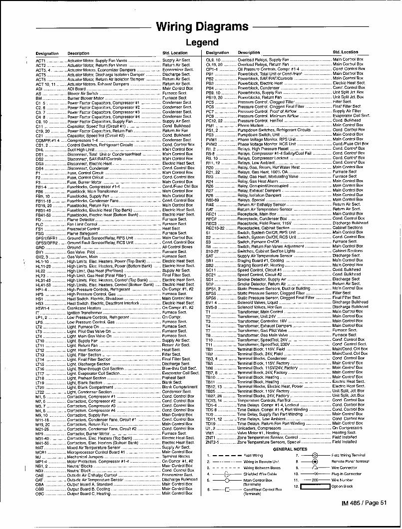
Wiring DiagramsLegend
Designation Description Std. Location
ACT1 Actuator Motor,Supply FanVanes Supply Air Sect.ACT2 Actuator Motor, Return Fan Vanes .. .. .. Return Air Sect.ACT3, 4 .............. Actuator Motors, Economizer Dampers Economizer Sect.ACT5 Actuator Motor, Discharge Isolation Damper Discharge Sect.ACT6 Actuator Motor, Return Air Isolation Damper Return Air Sect.ACT 10, 11 ......... Actuator Motora, Exhaust Dampera Return Air Sect.ADI .....................ADI Soard .................................................................... Main Control BoxAS ... . Blower AirSwitch ........................................................ Furnace Sect.BE ...................... Burner Slower Motor .... ... .. . .. Furnace Sect.Cl, 5 .................. Power Factor Capacitor, Compressor #l .... Condenser Sect.C2, 6 .................. Power Factor Capacitor, Compressor #2 Condenser Sect.C3, 7 .................. Power Faclor Capacitors, Compressor #3 Condenser Sect.C4, 8 ......... ......... Power Factor Capacitor, Compressor #4 Condenser Sect.C9, 10 ................ Power Factor Capacitor, Supply Fan Supply Air Sect.Cll ... .. Capacitor, Speed Trol (Circuit #1) .. . ..... . Cond. BulkheadC19, 20 .............. Power Factor Capacitors, Return Fan Return Air FanC21 Capacitor, SpeedTrol (Circuit #2) Cond. BulkheadCOMPR.# 1-4 Compressors 1-4 .. .... ..... ... ..... . Condenser Sect.CS1, 2 ................ Control Switches, Refrigerant Circuits Cond. Control BoxDHL Duct High Limit .. ... .... .... .... .... Main Control BoxDSI Disconnect, Total Unit or Condenser/Heat Main Control BoxDS2 Disconnect, SAF/RAF/Controls Main Control BoxDS3 Disconnect, Electric Heat Elactric Heat Sect.DS4 Oiaconnect, Condenser . ...... .... ... ... Cond. Control BoxF1 Fuse, Control Circuit ... ..... ..... .... .... Main Control BoxF2 .. ... . Fuse, Control Ciicuit ................................................... Cond. Control BoxF3 Fuse, Burner Motor .. .... .... ... ..... Main Control BoxFBt -4 ................. Fuseblocks, Compressor #l-4 . .... .... ...... Cond./Fuse Ctrl BoxFS6 Fuaeblock, Main Transformer . .... .... .... Main Control BoxFB9, 10 .............. Fuseblocka, Supply Fan ...... .... ... .... Main Control BoxFB1 1-18 ............. Fuaeblocks, Condenser Fans ..... ... ... Cond. Control BoxFB19, 20 ............ Fuseblocks, Return Fan .............................................. Main Control BoxFB31-40 Fuseblocks, Elactric Heat (TOP Bank) .... .... .. Electric Heat Sect.FB41-50 Fuseblocka, Electric Heat (Bottom Bank) Electric Heat Sect.FD Flame Detector ............................................................ Furnace Sect.FLC Fan Limit Control ......................................................... Furnace Sact.FS1 Freezastat Control ... .... .... .... .... Heat Sact.FSG Flame Safeguard .. .... ..... .... .... . Furnace Sect.GFSIIGFR1 Ground Fault Sensor/Relay, RPS Unit Main Control BoxGFS31GFR2 Ground Fault Sensor/Relay, RCS Unit Cond. Control BoxGRD Ground ........................................................................ All Control BoxesGV1 Gas Valve, Pilot .. . .... ...... ... .... .. Furnace Sect.GV2, 3 . ............... Gaa Valves, Main ... ...... ...... ..... .... . Furnace Sect.HL1-10 .... . High Limits, Elec. Heaters, Power (Top Bank) Electric Heat SectHL11 -20 ............. High Limits, Elac. Heaters, Power (Bottom Bank) Electric Heat Sect.HL22 High Limit, Gas Heat (Prafiltera) .... .... . ..... Supply Ah Sect.HL23 High Limit, Gas Heat (Final F6tar) .... .... . ..... Final Filtar Sact.HL31 -40 ............. High Limits, Elec. Heaters, Control (Top Bank) Elactric Heat Sect.HL41 -50 ........... .. High Limits, Elec. Heaters, Control (Sottom Bank) Electric Heat Sect.HP1-4 High Pressure Controls, Refrigerant .... ..... ... On Compr. #1, #2HP5 High Pressure Control, Gas .... ..... .... ...... Furnace Sect.HS1 Heat Switch, Electric, Shutdown Main Control BoxHS3 Heat Switch, Electric, Deadfront Interlock Electric Heat Sect.HTR1-4 Crankcase Haaters ..................................................... On Compr. #1, #2IT ignition Transformer ..................................................... Furnace Sect.LP1, 2 ................ Low Pressure Controls, Refrigerant On Compr.LP5 Low Pressure Control, Gas .. .... .... .... Furnace Sect.LT2 Light, Furnace On ... ..... ..... .... .... Furnace Sect.LT3 Light, Pilot Gaa Valve On .. ..... ... ...... Furnace Sect.LT4 ... .. Light, Main Gas Valve On ............................................ Furnace Sect.LTIO Light, Supply Fan ........................................................ Supply Air Sect.LT1l Light, Return Fan .. ... ..... .... ...... Return Air Sect.LT12 Light, Heat Section ... .. . ... .... Heat Sect.LT13 ... .. Light, Filter Section ..................................................... Filter Sect.LT14 Light, Hnal Filter Section Final Filter Sect.LT15 ... .. Light, Discharge Section . ... ...... ..... ... Discharge Sect.LT16 .... . .. Light, Blow-through Coil Section .. . .... .... .. Blow-thru Coil Sect.LT17 .. ... Light, Evaporator Coil Section ... .... .... Evaporator Coil SectLT18 Light, Praheat Section .. . ...... .... ... .. Preheat Sect.LT19 Light, Blank Section ... ...... .... .. . .... Blank Sect.LT20 Light, Blank Compartment .... . ... .. . .... Slank CompartmentLT22 Light, Condanser Section .... .... .... ..... Condenser Sect.Ml, 5 .................. Contractors, Compressor #1 .... .... ... .... Cond. Control BoxM2, 6 .................. Contractors, Compressor #2 ... ..... .. .... Cond. Control BoxM3, 7 .................. Contractors, Compressor #3 .. ..... .... .... Cond. Control BoxM4, 6 .................. Contractors, Compressor #4 .. . .... ... . .... Cond. Control BoxM9, 10 ................ Contractors, Supply Fan ............................................... Main Control BoxMl 1-16 ............... Contactora, Condenser Fans, Circuit #1 Cond. Control BoxM19, 20 .............. Contactora, Return Fan .. . .... ... ... .. Main Control BoxM21-28 Contractors, Condenser Fans, Chcuit #2 ... ..... Cond. Control BoxM29 Contactor, Burner Motor . .... ... .... .. Furnace Sect.M31-40 Contractors, Elec. Heaters (Top Bank) Electric Heat Sect.M41-50 Contractors, Elec. Heaters (Bottom Bank) Electric Heat Sect.MAT Mixed Air Temperature Sensor Supply Air Sect.MCB1 Microprocessor Control Board #1 ... ... .... Main Control BoxMJ Mechanical Jumpers . ... .... .... ... Terminal BlocksMP1-4 Motor Protectors, Compressor #l-4 On Compr. #1, #2NB1, 2 ................ Neutral Blocks ............................................................. Main Control BoxNB3 .,.................. Neutral Block . .. ... .... .. ... Cond. Control BoxOAE Outside Air Enthalpy Control . ... . ... . Economizer Sect.OAT Outside Air Temperature Sensor Discharga BulkheadOBA Output Board A, Standard .. . .... ... Main Control BoxOBB Output Board B, Cooling . ... .. .... Main Control BoxOBC ..................Output Board C, Haating . .. .. .. Main Control Box
Designation Description Std. Location
OL9, 10 .............. Overload Relays, Supply Fan Main Control Box0L19, 20 ............ Overload Relaya, Return Fan Main Control BoxOP1-4 Oil Preaaure Controls, Compr. #l-4 Cond. Control BoxPB1 Powerblock, Total Unit or Cond. /Heat Main Control BoxPB2 .... Powerblock, SAFIRAF/Controls .... .... ..... Main Control BoxPB3 Powerblock, Elactric Heat . .. . .... . .... ....... Electric Heat Sect.PB4 Powerblock, Condenser Cond. Control BoxPB9, 10 .............. Powarblocks, Supply Fan ... ..... ... .... Unit Split Jet. BoxPB19, 20 ............ Powerblocks, Return Fan Unit Sptit Jet. BoxPC5 Pressure Control, Clogged Filter Filter Sect.PC6 Pressure Control, Clogged Final Filter Finaf Filter Sect.PC7 Pressure Control, Proof of Airflow Supply Air FiltarPC8 Pressure Control, Minimum Airflow Evaporator Coil Sect.PC12, 22 ............ Pressure Control, FanTrol ..... ..... . .... ... Cond. SulkheadPM1 Phona Modem ... ..... ...... ..... ...... .. Main Control BoxPS1, 2 ................ Pumpdown Switches, Refrigerant Circuits Cond. Control BoxPS3 ..... ...... Pumpdown Switch, Unit ...... ........ ..... ...... Main Control BoxPVM1 Phase Voltage Monitor, RPS Unit Main Control BoxPVM2 Phase Voltaga Monitor, RCS Unit ...... ...... .... Cond.lFuse Ctrl BoxRl, 2 .................. Relays, High Pressure Reset ...... ....... ...... Cond. Control BoxR5-8 Relays, Compressor #l-4 Safety/Cool Fail Cond. Control BoxR9, 10 ................ Relays, Compressor Lockout ...... . ..... ...... Cond. Controf BoxRll, 12 ... ........... Relays, Low Ambient ... .... . ...... . ..... ....... Cond. Control BoxR20 ... .... . Relay, Gaa, Steam, Hot Water Heat ...... ..... Main Control BoxR21, 22 .............. Ralays, Gas Haat, 100”A OA ...... . ...... ...... . Furnace Sect.R23 Relay, Gas Heat, Modulating Valve Furnace Sect.R24 ..... .. Ralay, Gas Heat Alarm .... ........ ....... ..... .... Main Control BoxR26 . .... . Ralay, Occupied/Unoccupied ...... ...... ...... .... Main Controf BoxR27 ...... .. Ralay, Exhaust Dampera . ...... . .... . ...... ... Main Controf BoxR28 Relay, Isolation Dampers ........ ....... ..... .. Main Control BoxR60-69 Relays, Special ........................................................... Main Control BoxRAE Return Air Enthalpy Sensor ......................................... Return Air Sect.RAT Return Air Temperature Sensor Return Air Sect.REC1 Receptacle, Main Box .... . ...... ...... ...... ... Main Control BoxREC2 Receptacle, Condenser Box ..... . ........ ....... Cond. Control BoxREC3 Receptacle, Field Power, 115V DLscharge BulkheadREC1O-22 Receptacles, Cabinat Section Cabinet SectionsS1 Switch, System On/Off, RPS Unit ...... ...... ..... Main Control BoxS2 ..... ...... Switch, System On/Off, RCS Unit Cond. Control BoxS3 .... ..... Switch, Furnace On/Off ...... ........ ..... ....... Furnaca Sect.S6 .... . ..... Switch, Return Fan Vanea Adjustment Main Control BoxS1O-22 Switches, Cabinet Section Lights ....... ........ ....... Cabinet SectionsSAT ... ...... Suppfy Air Temperature Sensor ........ ....... ...... Discharge Sect.SB1 Staging Board #1, Cooling .... . . ...... ..... . ....... Main Control BoxSB2 Staging Board #2, Heating .... ...... ...... . ....... Main Control BoxSC11 Speed Control, circuit #1 .... ...... ...... ...... Cond. BulkheadSC21 Speed Control, circuit #2 .... ........ ..... ....... . Cond. BulkheadSD1 Smoke Detector, Supply Ah . ........ ...... ...... Discharge Sect.SD2 Smoke Datector, Return Air ....... ...... ...... Return Air Sact.SPS1, 2 .............. Static Pressure Sensors, Duct or Building Main Controf BoxSPS5 Static Pressure Sensor, Clogged Filter Filter Sect.SPS6 Static Pressure Sensor, Clogged Finaf Filter Final Filter Sect.SV1-4 Solenoid Valves, Liquid ....... ...... ....... ..... Discharge BulkheadSV5-8 Solenoid Valves, Hot Gas ........ ...... ....... ...... Discharga BulkheadT1 Transformer, Main Control ...... . ....... ...... ..... Main Control BoxT2 Transformer, Unit 24V .... ....... ..... ...... ... Main Control Boxr3 Transformer, Controller, 18V . ........ ..... ....... Main Control Boxr4 Transformer, Exhauat Dampars ....... ....... ...... Main Control BoxrT ..... .... Transformer, Gaa pilot Valve ...... ...... ....... Furnace Sect.r6 Transformer, Gas Main Valve ...... ..... ........ Furnace Sect.r10 Transformer, SpaedTrol, 24V ........ .... . ...... . Cond. Control Boxrl 1 Transformer, SpeedTrol, 230V ...... ..... ...... . Cond. Controf Sect.rBl Terminal Block, 115V, Fiald .... . ...... ...... ....... Main/Cond. Ctrl BoxrB2 Terminal Block, 24V, Fiald ...... ....... ...... ........ Mair_JCond. Ctrl BoxrB3, 4 ................ Terminal Slocka, Condenser ........ ...... ...... .. Cond. Control BoxrB5 Terminal Block, 115V, Factory ....... . .... . ...... . Main Control BoxrB6 Terminal Block, l15V/24V, Factory Main Control BoxrB7, S Terminal Slock, 24V, Factory ...... .... ..... ... Main Control BoxrBIO Tarminal Block, Heating ..... ....... ....... ..... . ... Main Control BoxrBll ..... .... Tarminal Block, Heating Elactric Heat Sect.rB12, 13 ............ Terminal Blocks, Electric Heat, Power Electric Heat Sect.rS25 Terminal Block, 115V, Factory ..... ...... .... ... Unit Spfit, Jet. BoxrB27, 26 ............ Terminal Blocks, 24V, Factory ..... ...... ...... ... Unit Spfit, Jet. BoxrC13, 14 ......... ... Temperature Controls, FanTrol Cond. Control BoxrD1-4 Time Delays Compr, #l-4, Lockout Cond. Control BoxrD5-6 Time Delays, Compr. #l-4, Part Winding Cond. Control BoxrD9 Time Delay, Supply Fan Part Winding Main Control BoxrDll, 12 ............ Time Delays, Low Ambient Cond. Control BoxrD19 Time Delays, Return Fan Part Wnding Main Control BoxJ1, 2 .................. Unloaders, Compressors On CompressorsJM1 Valve Motor #1, Heating ..... . ...... ..... .... Heating Sect.?NT1 Zone Temperature Sensor, Control Field Installed?NT2-5 Zone Temperature Sensors, Special Field Installed
GENERAL NOTES
1, ----- Field Witing 7 ~ “e’”~’”g’’~’””2. —--—- -— Wiring in Remote Unit a ~ Remote Panel Tarminal
3. --- – – - - Wiring Between Boxes e. ~ Wre Connector
4. ;)... Shielded Wire Cable 10. ~~ Plug-in Connector
5 ~ ;:;;::~l BOX 11. —200— Wre Number
6. ~ CondlHeat Control Box 12 ~“p””” “0”
rrerminals)
IM 485 I Page 51

Typical Power Circuits
FJG 1To crmmsson FUSE SLm,sIN FL.5E SCX W -NSEPCMROL ax MN mrcnas
I-F”CSEE — m -,,,,
PH4SE<JU_TAGEr
L1-lm Ml@ FB10 FB2LI
(%j$=:
T,
1!5V L5LTI+ II GRCI.I
—,,,—a,
-*,2-
—!, F=,
—!, +
—,t7—
—,!*-
—,, +
—,-
—,.,-
—:m-
—,%
Page 52 I IM 485

Typical Power Circuits (cent’d)
FROM . PO 1/0S 1,IN MAIN CONTROL BOX
+
LINE CCW.
w
FBI ‘B u ‘3— 7*
1, 72 13
:3
E,2 :3COIIPR . 3
MTR.t ~’
,
!3
:3
FROM<P61/0S 1,IN HAIN CONTROL 03X
-,03-
- 7“—
- ‘I-
-7,6—
-,,,—
-,,,-
- 7?2—
- m—
-724-
- ,2n-
—7z+-
—7sa-
-7w-
—7m-
-7m-
- 7s5-
IM 485 I Page 53

Typical Main Control Circuit (VAV Units)
‘w ,.
51
508 y
C’XJT ,Oto,,, ,0
mm,,,.
. . W,,!,WCRN, W
mm LW,
3
I 11111111111+
I1111111111rh--wIl. I rkl+wl
‘L 24 vmrs ..C. FRCM TRbNSF. tT21 —
47 533 mm, 534
—74. —
—742—
NB2
let
,
0

Typical Main Control Circuit (CAV-ZTC Units)
LINE ICONT.
l— 1 15/60,1 —1(
32
–.x, –
–~, –
–2@–
–20–
–.%–
–x7–
–m8–
-2w–
—?, O—
–,, ,–
—,,2-
–,,, –
–*t. –
-,,, –
-,,6–
—217–
-2,8–
–,,.–
—,*,-
—z2!–
–222-
– z,3–
-2>. –
-2%–
– 2?. –
-2,7–
–22e-
— ,,9-
- 2,a–
–,, t–
— 2,,-
WE IlHICRO
CONTRNBRO-25L?>
I%’,I—.,+,J
rm,?I ,~,
7 ,7
e
I
.. . . . ~kmr!wSE IPOINT
‘E
,W+ @&69—3
0,
COOL 1!83 5W* &=ssO.
1
$EIPO lN14 ,tim~ @=s79—
WLLSTAT——— 6 C.”oa *4,
“’E:== IJRIB. mm
—23,–
—,,7-
1- 24 WITS . . C. FROM lRoNSF. 1121 e –25–c
e
47
1“
101
54e
~&$lJ&D533~-53’f
——— ———~537
700
cl,
-- I. ‘● 2 02
l-m I
–25. -
“’J i ‘-–25–
-23–m
ml I(CCNT.)
04 —%2-
–26–
–*. –3—518
08
–?65–
–z6–
–26—
-26–
–,7, –
–z7. –
–,75–
– ,76 –
— 2,, —
—27, —
–2a–
~ ;#;J-p&_&~ w+w$mxEccTmm$*EcLo ‘–-NOIE 10 FIELOO
.*Nm, *FI ,[,. w+. m *LIED.SWPL, EO. T* ,“, ) 6srwc,N ,Em+,..,s.52 .53 cm .53 .5. -r K REMOVED. 72a
1 72s
–2a–
–a2–
–m4–
N3
IM 485 I Page 55
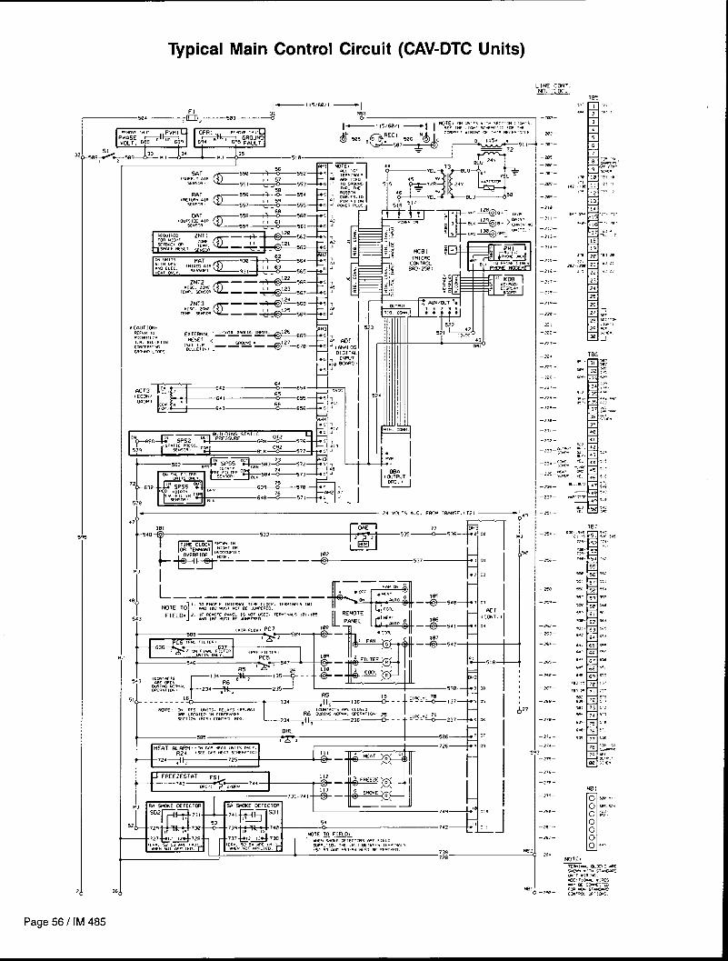
Typical Main Control Circuit (CAV-DTC Units)
LINE ICCfiT
I
T
1- 24 vm~s O.C. ma. WIMW.CT2, _
e
—.-*——,,,–
–ml–
—.5. —
—7>–
–?A–
— 7.. —
—a2—
–2$–
—=. –
–26–
–=, –
–K, —
–2%–
—2., —
—,.>—
—,., —
!
—2E–
—,,, —
—2-, –
–,7. –
–m–
-x-
—m2—
–.w. –
----

Typical Actuator Control Circuit
s
N
w ‘-tiii!iEEm415
—622 623 I :=;~...32,,31
(cccw IEO/V4. CC71PlE0)
—637 F== 66SIL, (w) L21
677 X12 78—
-76, ~~j 76qA7=*emq--’;62_
6CT5-ALIX
L, {SAF 16U. ) L2736
B 115V *
114
@-626+-*6214
116 R26 117 119
-*W=* @j636~-&631~
(ExT. #4_wW 61W4L1 twxc?lEO/LNoxwlm)(SEE NIIE .2 en .3. ,
[VW mx S16WIL1(SEE Km .2. )
WTES 1. ) T1632 CWWIC16 A% Fm V% IN A 24 VCLT A.C. CMSS .2 CISCUIT.2. J 3CLID STATE WCPUT R2LAVS W3T WITCH ‘.’. C.. LEMD3.
LOAO VU-TAGS 7wT1ffi = 24 VCtTS A.C.WIX. L0r30 ~MT = 1.W AT +65-C t 14YF1 CON11WW3.MIN. mm Ctnwwn = 313!A.
3.1 324.10 S1fITE CSJTPUTSELAY {@AS} 1S C1.OSCOCWIINO NW(W. WEW,T1CM6.
?FCFSR TO [M .483 Fm EXTERNfl mORX WIFUT 3E13WKE.
4.1 A 1SW31EN1 P601scr!w 02v1cE (w) Is PROvIm AcRuss mzEACH 3W.lCI STA7E 6EL6Y WIW1.
LrNE C~T. ~.
+s g
= I 83
104) —3w-
$- 1s5
1 :$4,,~,-2a,-“%%*.mI07
,
g. lml_m- ms ,,@
m 111-327-= ;::. 112
;:: : 113_J20.~ - 114
“t ,,5
,3 = 11s
- 117, —226— - Ila
rJ, ,,q- 337—
= lzn
$@ 121
=1 22-3m - ed7 , ~~
-1 24
- 34@— ml 25
126
—34, — 127
–242-Un, B.# , 26
am.-, , ~
—343- W,m, ,~
– 345–
-246-
—349-=
– 2%–
—35, —
- 352—
— n3—
–3s4-
- 355—
– 2%–
—3s7–
— n8-
— 3w—
–%B–
– 262–
– 263-
– 3v5–
- 396—
- r37—
TB7
Hman
~q7-
Typical Supply/Return Fan Control Circuit
‘=
37 OL10 OL9 OL20 OL19
-
60012
.763
]B
6“’*6’’*’’’=6’’~G’=*NB=* NB’ ‘30’-’” T:
qg~607 cl M9 —302—121 ma -J,
L
1 C2 615
I SOL. DrwIPERS612603 39
~+614+~~~
-303—119 39
40
UNIT CODED FOR PRRT MI NO I NG
SUPPLY FAN61%&’’%@=”
-304-121
RETURN Fr3N
15 HP AND hBOVE. 15 HP AND ABDVE . NOTE: A TRANSIENT PROTECTION OEVICE( MOV) IS PROV IOEO ACROSS EACHSOL 1D STATE RELAY OUTPUT.
IM 485 I Page 57

Typical Condenser Control Circuit (2-Compressor/4-Stage)
—
—
*??; ‘q&
~,3,t?
+.,-J I --’-
113
-,,7
+““’+==q
REFRIGERANT
CIRCUIT ●1
R5-l18+&l
——— I
k i4a—
d=.J PAP1 wINDING .<,
TD5 ‘CR,
,,~~!’””
—-~.8:.1-—,,,.1,–,,6
—,!- @-
t-“’=’”+13 -“”11563”,
—’-=’’’+’”‘“m% “: i_Jw
-21,
REFRIGERANT
CIRCUIT ●2
NOTE,
,. 1 a 1R,lN51ENT PRO, ECTIW DEvICE‘!!0” , IS FROV, CED ACROSS EACHSm !0 slaTE RELaT Ourwr.

—
—
—
—
1
4
Typical Condenser Control Circuit (4-Compressor/8-Stage)
‘2lL-MI-Cwxl HTR- I
—’”~i~ .~~co ‘“~HEaTER 2
-— ,’34--
-- L-’’6~.. & 32,-I I -B’”-lU1
“’++::: ,& 114
Ill -AUX2
H3-AUX2316~&317
REFRIGERANT CIRCUIT ● !
r——-— ———_ —_____10
oSB-CCUT.
,4L177~
~:
1783--- %-&.31 e#~31’?10 .
RI 0’3—263 ,1:2 m ~::”
H3-AUX1 HTR-333133$ W,- co
-. .%.. -==4.17@i-r~171L:~K,,,&44174 ~2
CCU.3 12
—e44-
1754---%-176 9WI .4 _e,5_
65,Ul:-”’ 2
I --- L426~.. *427.-J I ---
1u
.2,2+#-&
Mz- AUX2213
M4 -AUX2.416* :7417
REFRIGERANT CIRCUIT ●2
r—— ——-— —_ —_____
02B-CIWT.18
24i277g
fg~e 4.?5 .~ ,3
12 !1278= ‘-- 2~418~~419
R2 0’4—403 ,YL2 405 Lw 4’”
1431
m-””’ T
433 - a%—
M4 - Aux 1431
HTR-4
-J
z“e~~ “’”ss -m-
‘,,i~,,, ‘1-~~ ~:fijji&[ lJ.
—m3—
NUTES THIS UNIT HAS 8 COOLINQ STAGES.274 0BB3
4’4
—m4-COU. 4 22
REFER 10 wIT I. I!. 3WLET1N FOR3EG03K1N3 W THE 6 COCt lW WTPUTS
275- — %276 987
, UI y“ “2 2 ‘2”4 –r=-
10 PROVIOE 8 STEP3 26 COCI-IN3.WTE* @ 1RW312NT FROTECT1m D2V1CE
— (WV) Is PROv[m nmws5 EMH3CL1O STATE FCLAY CUIWT.
IM 485 I Page 59

Typical Gas Furnace Control Circuit (Modulating Burner, Mixed Air Intake)
+L!NS CCUT.
-Ea–
—$81 –
-m--, ,
—w-—
–6 *—
—,,,—
NOTE ,
1 I , -,.,.
—6,. –
-6,5-
–6 5– 2Z
- sm-
-s2!-
–52–
-6. –
—6x–
_=— S42.4,
—sJz-
—6, .—
-.n -
,48 ~_ 4
!. POCR. PILO? fi~ WIN VWVE 1-lC.TICWLZWT5 ARI PPRT Of T* FLM 5ffECUam,FSG , COWRWLER.
2. a TRnNSIENr maTEcr ION WTCE cmv, ISIWO” [LIED aCROSS EdCH SOL ID ST61E REL6Y W,WT “KT&i3:?:::2mj2 z
1 8FLC4T, %, . .- , m5
Sequence of Operation: When the rooftop unit is energized, 120 volt power is supplied through the system on-off switch S1 to OBA3 contacts. Upon a calf for hezt.the control system will close 0BA3, thus energizing relay R20. 120 Volt power is furnished through the system on-off switch S1, through relay R20 closed contacts.through the burner on-off switch S3, through the high limit control FLC and through the optional automatic reset low pressure switch LP5 and the optional manual resethigh gas pressure switch HP5, to power terminal 6 on the flame safeguard control FSG. The flame safeguard then energizes its terminal 4, which powers the burnercombustion air blower motor BM. Blower operation is sensed by the air switch AS which makes terminal 6 to 7. After a 90-second prepurge period. terminal 8 (pilot gasvalve GV1) and terminal 10 (ignition transformer IT) will be energized. The pilot flame will ignite and be detected by the flame safeguard through the flame rod FD. Upondatection of pilot flame, terminal 10 (ignition transformer IT) will be de-energized and terminal 9 (main gas valves GV2 and Gv3) will be energized and the main flamewill coma on. Also, the flame safeguard contains LEDs (lower left corner) that will glow to indicate operation.
Low fire start is provided by relay R23. The relay drives the gas valve actuator VMI to the minimum firing rate position tienever the flame is not on and holds itthere until the flame has lit and been proven.
Whenever the burner is in operation its firing rate will be determined by the “floating” gas valve actuator VM1. This actuator positions the butterfly gas vafve andcombustion air damper and can set the firing rate between 33% and 1007. of normal rate. When the main control system closes OBA5, the gas valve actuator w“IIreposition toward a higher firing rate until either OBA5 opens or the actuator reaches its maximum position. When the main control system closes OBA4. the actuatorwill reposition toward a lower firino rate. [f neither OBA4 or 0BA5 are closed, the actuator will remain at its mesent Dosition.–r.–.–
In the event the pilot fails to ig~te or the flame safeguard fails to detect its flame within 10 seconds, terminal 4,8,9 and 10 w“ll be de-energized. thus de-energizingthe burner. The flame safeguard would then be on safety lockout and would require manual resetting. The heat alarm relay R24 would then be energized and wouldthen energize the remote “heat fail” indicator light and send a fail signal to the MicroTech input board ADI.
If the unit ove~eats, the high limit control FLC will cycle the burner limiting furnace temperature to the limit control set point.
Piping Diagram
—6w–
—,,. -
Page 60 I IM 485

Typical Electric Heat Control Circuit (Multistage)
I
\
ELEC
FB31 H31
Ll 18 t., +“ ::i’3’’Em’E “’ ‘“’”:7:””
{ +L2 72
1
s “%
‘:1*E2’2 4 “
k’=’”
L3
L3 13HTR .Oh
L1
L2
L3
FB34 H34
,, ~ez’ :~’~sf’m”-’ ,,
HTR .4A
LI 11
L2 12
: “%
‘i ‘*”o 2 4 ‘2
L’W’”
L3
i?%HIR ●OA
L!
L2
L3
168KU,4S0 I
I_ .-,
CIRCUIT ●3 WTES,
+
L lNE CONT.
7-
1. X RZ5EIH!. LIMITS (*1.161 MEw uwmw fm C.S. A. wmva WTS.
:y+l @y
2. 7-SLCSK 11B121n1REs .881 ..063W LW2ER WPLY M C4_L MIRES
UJ
F#4,.=~~~Jyl *1 E
- mO—
=1 12 73
1 I u
-5,7-
-Oln —
-sl$-
-aa–
-*21–
- 52z-
-sm-
—s24-
—025-
- m?*—
- 827—
— 020-
NW MR7HS3
‘f,,,=~=a –: _ 1I 5 VOLT A. C. FROM MAIN CONTROL 00X —“”G ----@89—
tWOLI*2 ?
I OBA3Iwro] 918
HS 1 94 HL31‘3&8m<~8e3
T8833& 84_g_ _805 s
K-..
901 , ~ 902-4
‘lR “1’y, M3!C2 ~;; -W@- 512
(m wIICH OR.4CKETIN llAtN CONTROLBOX)
Inlno]HL41
933
931l>2q32
‘n “!;, WIC2o-@-”’-”2
t
pmg[WTol ‘HL32
::;+ &E6-.%- —q5
E 7.,
9s89’66 , =2 W7
a
“TR “z{?, 32C2 9,3 ‘C64- S10
l#JJlolHL42
936 937938‘n “216:, 42CZ ~43 -S66- 510
00A5Iwlol
ee7qg88*_g_ _em ,2 ,,
‘v’’’G’”
‘7n “3/7;, 33 ~2 913 –878– 024
L—
p~!(AUTO)r
97 HL34w+ $p& —
=1’63
E = .,.
916 ~ ~ 917
:~
‘ln “y, 34 ~2 918 –574– S?9940
(Au701HL44
94612
947 ‘Tn ““y, 44 ~z 940 -376-$20
IM 485 I Page 61
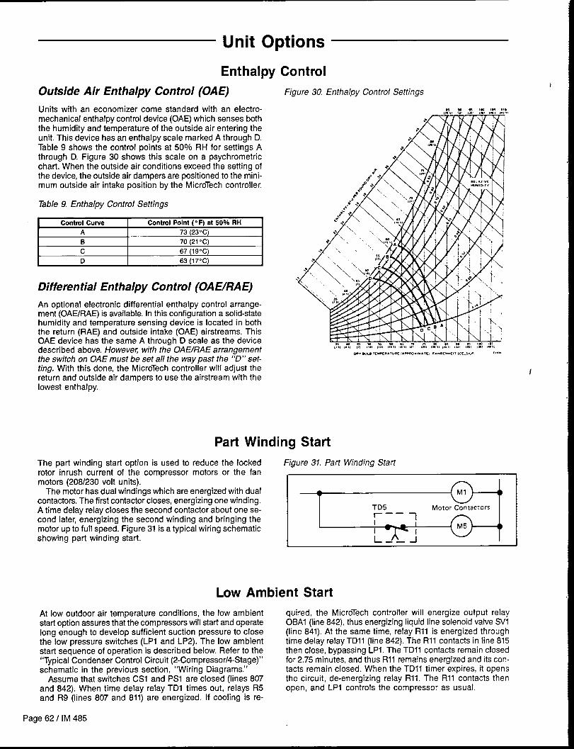
Unit Options
Enthalpy
Outside Air Enthalpy Control (OAE)
units with an economizer come standard with an electro-mechanical enthalpy control device (OAE) which senses both
the humidity and temperature of the outside air entering the
unit. This device has an enthalpy scale marked A through D.Table 9 shows the control points at 50% RH for settings A
through D. Figure 30 shows this scale on a psychometric
chart. When the outside air conditions exceed the setting of
the device, the outside air dampers are positioned to the mini-mum outside air intake position by the MicroTech controller.
Table 9. Enthalpy Control Settings
Control Curve Control Point (“F) at 50% RH
A 73 (23C)
B 70 (21”C)
c 67 (19”C)
t–,
D 63 (17C) I
Differential Enthalpy Control (OAEIRAE)
An optional electronic differential enthalpy control arrange-ment (OAE/RAE) is available. In this configuration a solid-statehumidity and temperature sensing device is located in boththe return (RAE) and outside intake (OAE) airstreams. ThisOAE device has the same A through D scale as the devicedescribed above. However with the OAEIRAE arrangementthe switch on OAE must be set all the way past the “D” set-ting. With this done, the MicroTech controller will adjust thereturn and outside air dampers to use the airstream with thelowest enthalpy.
Control
Figure 30. Enthalpy Control Settings
Part Winding Start
The part winding start option is used to reduce the lockedrotor inrush current of the compressor motors or the fanmotors (208/230 volt units).
The motor has dual windings which are energized with dualcontractors. The first contactor closes, energizing one winding.A time delay relay closes the second contactor about one se-cond later, energizing the second winding and bringing themotor up to full speed. Figure 31 is a typical wiring schematicshowing part winding start.
Figure 31. Part Winding Start
i )
TD5 Motor Contractors1-
——
I1
i 4)
L —— J
Low Ambient Start
At low outdoor air temperature conditions, the low ambient quired, the MicroTech controller will energize output relaystart option assures that the compressors will start and operate OBA1 (line 842), thus energizing liquid line solenoid valve SV1long enough to develop sufficient suction pressure to close (line 841). At the same time, relay Rll is energized throughthe low pressure switches (LPI and LP2). The low ambient time delay relay TD11 (line 842). The Rll contacts in line 815start sequence of operation is described below. Refer to the then close, bypassing LPI. The TD11 contacts remain closed“Typical Condenser Control Circuit (2-Compressor/4-Stage)” for 2.75 minutes, and thus Rll remains energized and its con-schematic in the previous section, “Wiring Diagrams.” tacts remain closed. When the TD11 timer expires, it opens
Assume that switches CS1 and PS1 are closed (lines 807 the circuit, de-energizing relay R11. The R11 contacts thenand 842). When time delay relay TD1 times out, relays R5 open, and LP1 controls the compressor as usual.
and R9 (lines 807 and 811) are energized. If cooling is re-
Page 62 I IM 485
1
/

Ground Fault Protection
The ground fault protection is designed to protect motors from control circuit to shut the unit down whenever a ground faultdestructive arcing ground faults. The system consists of a condition exists. The ground fault relay is self powered. Theground fault relay and a ground fault current sensor. The ground fault sensor is a current transformer type of deviceground fault relay employs solid state circuits that will instan- Iocated on the load side of the power block through whichtaneously trip and open a set of relay contacts in the 115 volt the power wires of all phases are run.
Phase Voltage Monitor
The phase voltage monitor protects against phase loss (single when all phase voltages are within specified limits. The phasephasing) when any one of three line voltages drop to 74% voltage monitor is located on the load side of the power blockor less of setting. This device also protects against phase with a set of contacts wired to the 115 volt control circuit toreversal when improper phase sequence is applied to equip- shut the unit down whenever the phase voltages are outsidement, and low voltage (brownout) when all three line voltages the specified limits.drop to 90% or less of setting. An indicator run light is “on”
Hot Gas Bypass
Hot gas bypass is a system for maintaining evaporator pres-sure at or above a minimum value. The purpose for regulatingthe hot gas into the distributor is to keep the velocity of therefrigerant as it passes through the evaporator high enoughfor proper oil return to the compressor when cooling load con-ditions are light.
The system consists of a solenoid valve piped in series witha pressure regulating valve as shown in Figure 33. The sole-noid valves are factory wired to open whenever the controllercalls for the first stage of cooling. The pressure regulatingvalve operates as shown in Figure 32. Since the bulb is fac-tory mounted in the discharge airstream where the ambienttemperature is about 55° F (130C), the chart indicates that thevalve is factory set to begin opening at about 57 psig (393 kPa).
This setting can be changed by changing the pressure ofthe air charge in the adjustable bulb (refer to Figure 33). Toraise the pressure setting, remove the cap on the bulb and turnthe adjustment screw clockwise. To lower the setting, turn thescrew counterclockwise. One turn is equivalent to a change ofabout 1 psi (7 kPa). Do not force the adjustment beyond therange it is designed for, as this will damage the assembly.
The regulating valve opening point can be determined byslowly reducing the system load or reducing the required
.
IM 485 I Page 63
discharge air temperature setting while observing the suc-tion pressure. When the bypass valve starts to open, therefrigerant line on the evaporator side of the valve will beginto feel warm to the touch.
Caution: The hot gas line mav become hot enough to causeinjury in a very short time, so-care should be taken duringvalve checkout.
Figure 32. Hot Gas Bypass Adjustment Range Chart
30UI 1 ‘ ‘ ‘ ‘ ‘3040 sosomso 9JIm 110
TEMPERATURE(“F) ATBULBLOCATION

SUCTION LINEHEADER
TO EVAPORATORDISTRIBUTOR TUBES
n
Figure 33. Hot Gas Bypass System
HOT GAS
NOTE: THIS FIGURE SHOWS REFRIGERANT CIRCUIT #1.
SUCTION ILINE
i
SpeedTrol
McQuay’s SpeedTrol system of head pressure control operatesin conjunction with FanTrol by modulating the motor speedof the last condenser fan of each refrigeration circuit inresponse to condenser pressure. By varying the speed of thelast condenser fan of each refrigeration circuit, the Speed-Trol option allows mechanical cooling operation in ambienttemperatures down to 0F (-180 C). SpeedTrol controllersSCI1 and SC21 sense refrigerant head pressure and vary thefan speed accordingly. When the pressure rises, SpeedTrolincreases the fan speed; when the pressure falls, SpeedTroldecreases the fan speed. The SpeedTrol controller’s throttlingrange is 170 to 230 psig (1172-1586 kPa) fixed.
The SpeedTrol fan motor is a single phase, 208/240 volt,
Page 64 I IM 485
I
~ :-
3/16HEX ‘.<” /lt)JuSTABl_E
WRENCH BULB
thermally protected motor specially designed for variablespeed application. Units with 460 volt power have atransformer mounted inside the condenser fan compartmentto step the voltage down to 230 volts for the SpeedTrol motor.A portion of a typical SpeedTrol power circuit schematic isshown in Figure 34.
SpeedTrol control starts to modulate the motor speed at ap-proximately 230 psig and maintains a minimum condensingpressure of 170 to 180 psig (1172-1241 kPa). SpeedTrol sen-sors are attached to the condenser coil discharge tubing bymeans of a schrader fitting.
A portion of a typical SpeedTrol power circuit schematic isshown in Figure 34.

Figure 34. SpeedTrol Schematic
G; ‘-,(~:&.,,-m!2----M --2
12
Cow=fl. 3‘---leki
MTR.1 ~’
4+”,,FB12 )412
q
s---w -u,1 11
‘-W%L.? 12
- ~~a
N/n m WITS .11.L3 13 ,3
-,4 15/4E0fi75v % $Tml. “,-
The optional Remote Monitor Panel provides remote indicatorlights and fan on-off and system heat-auto-cool switches. Referto Figure 35.
Wiring should be sized in accordance with Table 10 andconnected to the panel terminals in accordance with the unitwiring diagram. The panel can be mounted on a standard 4 x 4junction box.
If the Remote Monitor Panel is not used, terminals 101 and105 must be jumpered to enable cooling, and terminals 101and 106 must be jumpered to enable heating. The fan is en-abled when either cooling or heating is enabled.
Table 10. Low Voltage Field Wiring
.~“Maximum wire length ia based on a voltege drop of 2 volts.
L—A
—7,6—
—7,7—
—7,7—
Figure 35. Optional Remote Monitor Panel
HEATAUTO;ooL- B
ONOFF E
—729-
—m-
-7?a-
❑❑•1•1•1•1
1
I
II
IM 485 I Page 65

Optional Remote Monitoring and Control Panel
One to eight applied rooftop units can be incorporated into Figure 37 Remote Monitoring and Control Panela network-with” the MicroTech Remote Monitoring and Con-trol (RMC) Panel. The optional RMC Panel provides the follow-ing keypad programmable features:● Remote unit monitoring (up to eight)● Common duct static pressure and heat/cool changeover
control of multiple VAV units (groups of two to eight)● Common zone temperature control of multiple CAV units
(groups of two to eight). Common unit schedulingFor further information refer to Bulletin No, IM 444, “MicroTechRemote Monitoring and Control Panel.”
mm”[
External Time Clock
An external time clock can be used as an alternative to (or condition in which the programmable internal schedule isin addition to) the MicroTech controller’s internal scheduling followed. When the circuit is closed, power is fed to DH1-1.function. The external timing mechanism is set up to open The MicroTech controller responds by placing the unit in theand close the circuit between field terminals 101 and 102. occupied mode, overriding any set internal schedule.When the circuit is open, power is not supplied to digital in- For more information, see the “Digital Inputs” section ofput D1 (terminal DH1-1) on the ADI board. This is the normal Bulletin No. IM 483, “MicroTech Applied Rooftop Unit Controller.”
Smoke Detectors
Optional smoke detectors can be located at the supply and- return openings. The wiring for these smoke detectors is
shown on any of the ‘Typical Main Control Circuit” schematicsin the “Wiring Diagrams” section of this manual.
The sequence of operation for these detectors is as follows:When the smoke is detected by either sensor, the normallyclosed sensor contacts open. This removes power from digitalinput DI 1 (terminal DH2-11) on the ADI board. The MicroTech
controller responds by shutting the unit down. The controller isplaced in the Alarm Off state, and cannot be restarted until thealarm is manually cleared. Refer to the operation manualsupplied with the unit for information on clearing alarms (seeTable 1).
The smoke detectors themselves must be manually resetonce they have tripped. Power must be cycled to the smokedetector to reset.
Freeze Protection
An optional freezestat is available on any unit that has hotwater or steam heating coils. The sensing element is locatedon the downstream side of the heating coil in the, heating sec-tion of the unit. If the freezestat detects a freezing conditionand closes, the MicroTech controller will take different action,depending on whether the fans are on or off. The freezestatis an auto reset type of control; however, the controller alarmit causes is manual reset if the fan is on and auto reset if thefan is off.
Fan On Operation
If the freezestat detects a freezing condition while the fan ison, the MicroTech controller will shut down the fans, close theoutdoor air dampers, open the heating valve, and set a10-minute timer. The MicroTech controller’s current alarm(menu 29) will be “Freeze Stat Fail.”
When the 10-minute timer expires, the controller beginschecking the freezestat again. If the freezestat is open, the
heating valve will close. If the freezestat closes again, theheating valve will open, and the 10-minute timer will reset.
The unit will remain shut down until the “Freeze Stat Fail”alarm is manually cleared. Refer to the operation manual sup-plied with the unit for information on clearing alarms (see Table 1).
Fan Off Operation
If the freezestat detects a freezing condition while the fan isoff, the MicroTech controller will open the heating valve andset a 10-minute timer. The MicroTech controller’s current alarm(menu 29) will be “Freeze Stat Prob.”
When the 10-minute timer expires, the controller beginschecking the freezestat again. If the freezestat is open, theheating valve will close. If the freezestat closes again, theheating valve will open, and the 10-minute timer will reset.
When the freezestat opens again, the “Freeze Stat Prob”alarm automatically clears. This feature protects the coil andallows the system to start normally after a cold night.
Page 66 I IM 485

Mixed Air Temperature Alarm
A mixed air temperature (MAT sensor and an associated “Low dicated when the supply air temperature exceeds the mixedAirflow Alarm” are provided on VAV units with gas or electric air temperature by more than 60° F (160C). In this case, a “Lowheat. The MAT sensor is located in the supply fan section of Airflow Alarm” is generated and heat will not be re-enabledthe unit at the supply fan air inlet funnel. until the alarm is manually cleared. Refer to the operation
Heat will be disabled whenever the airflow is detected to manual supplied with the unit for information on clearingbe too low for safe heating operation. This condition is in- alarms (see Table 1).
Duct High Pressure Limit
The duct high pressure limit control (DHL) is provided on allVAV units, including the CAV-DTC unit that can be field con-verted to VAV. The DHL protects the ductwork, the terminalboxes, and the unit from overpressurization which could becaused by, for example, tripped fire dampers or control failure.
The DHL control is factory set to open when the dischargeplenum pressure rises to 3.5” W.C. (872 Pa). This settingshould be correct for most applications; however, it is ad-justable. Removing the front cover of the device reveals a
Variable
Variable inlet vanes are installed on the supply and return fansof VAV units. They are also installed on the return fans of con-stant volume units that have direct building static pressurecontrol capability.
The inlet vane assemblies consist of airfoil type inlet funnelswith integral sets of lever-actuated radial vanes. The supplyfan has one assembly on each side of the fan, and the returnfan has one assembly on the inlet side of the fan only. Whenthey open, the inlet vanes direct air in the direction of wheelrotation.
The vanes are able to rotate 90° from full closed to full open.A stop limits the amount of travel open and must not bechanged. Driving the vanes past this stop will cause the vanehub cam linkage to disengage. If this occurs, the vanes willturn independently of each other, and the hub assembly willhave to be overhauled.
The moving parts of the vanes are permanently lubricated.All threaded fastenerstightness.
I
must be periodically checked for
scale showing the current setting. Turning the adjustmentscrew located on the bottom of the device adjusts the settingup or down.
If the DHL switch opens, digital input D7 (terminal DH1-7)on the ADI board will be de-energized. The MicroTech con-troller then shuts down the unit and enters the Off-Alarm state.The alarm must be manually cleared before the unit can startagain. Refer to the operation manual supplied with your unitfor more information on clearing alarms (see Table 1).
Inlet Vanes
Suppy Fan Vane Adjustment
Figure 36 shows the supply fan vane linkage assembly. Bothsets of vanes on the supply fan must operate in unison. If theydo not operate in unison, adjust the length of the floating link(Point B) until they do.
As shown in Figure 36, the vane actuator crankarm musthave a 180” rotation, and the crankarm radius must be 2.80inches (71mm). Do not make linkage adjustments to compen-sate for improper actuator rotation. Instead, correct the ac-tuator rotation adjustment. Refer to “Actuator Rotation Adjust-ment” below for instructions.
Inlet vanes must not be adjusted to close tight during fanoperation. A minimum of 5° open is recommended to avoidfan pulsation. Units with factory installed MicroTech controlswill automatically open vanes 5“ prior to startup.
Note: There are two different actuator linkage configura-tions. These are shown as View #1 and View #2 in Figure 36.Refer to Table 11 below to determine which view applies toa particular unit. Use dimension “Z” to determine the fanwheel size.
IM 485 I Page 67

Figure 36. Supply Fan Vane Assembly
VIEW #1/-
/- —-. \
/, OPEN
----
“z’\
h’/
/’/
I
IIi,I,\
.,\
.,\
● ,Ci \‘\ \ _.— _ \
//
(BOTH SIDES)-/ -—-\
FLOATING .\
“;~ “ADJUSTABLE
#/
(lIA, (z9mm) SLOT
*‘\
10
0
\ / --. . . L
\/ . /
\.
VIEW #2 ,’ “\ \/’
‘\‘\ ‘\
,“ \ d
./’
36” WHEEIJ50 HP ‘\ .’-— --WHEEU50-60
\
I
iIi1 i
/’/’
CLOSED/ ‘
/’--
HP /oPEN‘/
i 27’~33° WHEEU;-40 HP36” WHEEL/5-40 HP
/’ 40” WHEEU15-40 HP\
ii;i
i/’
/’
Page 68 I IM 485
/,
Table 11. Applicable Actuator Linkage Configurations
Supply Fan “z”Motor
Figure 36
Wheel Size (Refer toHP
Reference
(in Inches) Figure 36) View
27 38.1 ( 966mm) 5—40 2
30 42.3 (1074 mm) 5—40 2
33 46.4 (1179mm) 5—40 2
36 51.5 (1306 mm) 5—40 2
36 51.5 (1308 mm) 50—60 1
40 56.8 (1443 mm) 15—40 2
40 56.8 (1443 mm) 50—75 1
\
1
I
I
I
I
J

Return Fan Vane Adjustment
The two possible return fan vane linkage assemblies areshown in Figures 37a and 37b. Figure 37a is for 40” fan wheels,and Figure 37b is for 44” fan wheels.
As shown in these figures, the vane actuator crankarm musthave a 180° rotation. The crankarm radius must be 2.30inches (58mm) for the 40” fan assembly, and it must be 2.65inches (67mm) for the 44” fan assembly. Do not make linkageadjustments to compensate for improper actuator rotation.Instead, correct the actuator rotation adjustment. Refer to
Figure 37a. Return Fan Vane Assembly (40” Wheel)
“Actuator Rotation Adjustment” below for instructions.Inlet vanes must not be adjusted to close tight during fan
operation. A minimum of 5° open is recommended to avoidfan pulsation. Units with factory installed MicroTech controlswill automatically open vanes 5” prior to startup.
As the actuator crankarm rotates from 0° to 180°, the vanesshould rotate from 0° (closed) to 90° (full open). If the ac-tuator rotation adjustment is correct and the vanes do not openproperly, change the linkage rod length. Do this by loosen-ing the nut, sliding the rod, and then retightening the nut atPoint A or Point B.
/
[ w-\\,i
; ‘- ‘-/—- —-— —-
“\CLOSED OPEN ,;
/‘\ . . /’
‘\ 2.30. . (58mm)
.0’‘\
/“’-\._-_--./.
Figure 37b. Return Fan Vane Assembly (44” Wheel)
. ..Z ----- -.-.4”
0 . . .
R. x.
./’ -.\.
/ -\.!
iii‘\“\+
\.\
.\ &-..
\.\<
\‘\ii
i
/“-.%. /“---- .*.---------
. .\B
“\. -“. -.-
.0,/
/
i
i‘\
.\.-- .(67mm)
IM 485 I Page 69
Actuator Rotation Adjustment block on the shaft side and engaging the screwdriver blade
The counterclockwise (as viewed from shaft end of actuator)with the edge of the notched cam nearest the front of the ac-
Iimit switch is adjustable on the Barber-Colman actuator. Thetuator. Turning the cam clockwise (as viewed from the shaft)increases the amount of actuator rotation. Each click of the
clockwise limit is not adjustable. The CCW limit setting canbe changed in the field by inserting a screwdriver through
cam represents about 3° change in actuator rotation. The ac-tuator should be set for 180° rotation.
the opening in the top plate directly ahead of the terminal
Convenience Receptacle/Section Lights
A convenience receptacle is provided in the main control box protected by a ground fault circuit interrupter (GFI) device.on all units. To utilize this receptacle, a separate field sup- Optional lights are available for certain sections in the unit.plied 115V power wiring circuit must be connected to the 115V Each light includes a switch and convenience receptacle, andfield terminal block TB1, located in the main control box. Note is powered by the external 115V power supply connected tothat the National Electrical Code requires that this circuit be TB1.
,
Page 70 I IM 485

Check, Test, and Start Procedures
Electric shock and moving machinery hazard. Can cauae severe equipment damage, personal injury, or death.
All start-up and service work must be performed by qualified technicians who are familiar with the hazards of working on this type ofequipment.
Do not attempt to operate or service this equipment without first reading and understanding this manual, the “MicroTech Applied Roof-top Unit Controller” manual (Bulletin No. IM 483), and the applicable operation manual (Bulletin No. OM 108, OM 109, or OM 110).
Assure that the frame of the equipment is bonded to the building electrical ground by use of the grounding terminal or by other accept-able means.
Disconnect electrical power before servicing this equipment.
All units are completely run tested at the factory to assureproper operation in the field. Nevertheless, the followingcheck, test, and start procedures must be performed to pro-perly start the unit. To obtain full warranty coverage, the check,test, and start form supplied with the unit must be completed,
1.
2.
3.
4.
5.
6.
7.
8.
1.
Before
Verify that the unit is completely and properly installedwith ductwork connected. Verify that all constructiondebris is removed, and that the filters are clean.
Verify that all electrical work is complete and properly ter-minated. Verify that all electrical connections in the unitcontrol panel and compressor terminal box are tight, andthat the proper voltage is connected.
Verify that gas piping is complete and leak tight. Verifythat the shutoff cock is installed ahead of the furnace,and that all air has been bled from the gas lines.
Manually rotate all fans and verify that they rotate freely.Verify that the belts are tight and the sheaves are aligned.
Verify that all setscrews and fasteners on the fan assem-blies are still tight. Do this by reading and following theinstructions in “Setscrews” which is in the “Maintenance”section of this manual.
Verify that the evaporator condensate drain is trapped,and that the drain pan is level.
If unit is curb mounted, verify that the curb is properlyflashed to prevent water leakage.
Before attempting to operate the unit, review the controllayout description to become familiar with the controllocations.
Review the equipment and service literature, the se-quences of operation, and the wiring diagrams to become
signed, and returned to the Commercial Products Group ofMcQuay International.
A representative of the owner or the operator of the equip-ment should be present during start-up to receive instructionsin the operation, care, and maintenance of the unit.
Start-up
9.
10.
11.
familiar with the functions and purposes of the controlsand devices.
Determine which optional controls are included withthe unit.
Before closing the power disconnect switch, open thefollowing unit control circuit switches:
a. Main Control Panel● Turn system switch S1 to “Off.”● Electric heat units: Turn switch HSI to “Off.”
b. Compressor Compartment. Turn compressor control circuit switches CSI, CS2
to “off.”● Turn liquid line solenoid valve switches PS1, PS2,
PS3 to “off.”
c. Furnace Control Compartment. Turn furnace switch S3 to “Off.”
If the VAV or CAV-DTC unit does not have an optional zonetemperature sensor (ZNT1) connected to it, change theentry under keypad menu item 28C (“Space Sensor=”)from “Yes” to “No.”
If desired, all MicroTech internal control timers can be
Power-up
reduced to 20 seconds by changing the entry underkeypad menu item 28B (“Timers=”) from “Normal” to“Fast.” This will reduce the delays associated with nor-mal control action for 15 minutes or until the entry ischanged back to “Normal.”
Close the unit disconnect switch. With the control system 2.switch (S1) in the “Off” position, power should only beavailable to the compressor crankcase heaters.
Turn the S1 switch to “On.” Power should now be sup-plied to the MicroTech controller, and the LED’s on MCBI(red, green, and amber) should follow the normal start-up sequence (refer to the “Component Data” section ofIM 483).
IM 485/ Page 71

Fan Start-up
1. If the unit is equipped with an optional Remote MonitorPanel, turn the on-off switch to “On,” and turn the heat-auto-cool switch to “Auto.”
2. Place the unit into the “Occ-Fan Only” mode throughkeypad menu 11 (“Control Mode”). The controller shouldenter the Startup Initial operating state. After the StartupInitial timer has expired (3 to 4 minutes), the fans shouldstart. Observe the fan rotation and, if it is backwards, dis-connect power and reverse two legs of the power supply.
If a fan does not run, do the following:a. Check the control circuit fuse (Fl).b. Verify that the overloads have not tripped.c. Check the fan motor power fuses.d. Verify that the Remote Monitor Panel wiring is correct
(if any).e. Trace the circuits.
3. If the fans are equipped with optional spring isolators,check the fan spring mount adjustment. When the fansare running they should be level. Refer to “Spring IsolatedFans” in the “Readying Unit for Operation” section ofthis manual for information.
Note: The supply and return fan drives are usually selectedfor operation in the drive’s midspeed range. The return fandrives are usually shipped with fixed pitch sheaves that willprovide the selected fan speed; however the supply fan drivesare usually shipped with variable pitch sheaves that are ad-justed to provide the minimum fan speed. Both drives shouldbe adjusted for proper airflow during air balancing. For moreinformation, refer to “Air Balancing” near the end of thissection.
Economizer Start-up
Improper adjustment may damage the dampers.I
I Assure proper damper adjustment. When an economizer is ordered without an actuator, the linkage requires a 3.14-inch linear stroketo fully open it. Do not allow dampers to be driven beyond their normal full closed or full open positions. I
1.
2.
3.
4.
Check whether the outdoor air is suitable for free cool-ing by displaying keypad menu 9. “Low” indicates lowoutdoor air enthalpy; “High” indicates high outdoor airenthalpy.
Referring to “Enthalpy Control” in the “Unit Options”section of this manual, verify that the enthalpy change-over control is working properly. You may want to taketemperature and humidity measurements.
Verify that switches PSI and PS2 are at “Off.” This willprevent compressor operation during the procedure.
At the keypad, set the cooling setpoints low enough sothat the controller will call for cooling. On CAV-ZTC units,adjust the “Cooling Spt =” entry on menu item 12C. OnVAV or CAV-DTC units, adjust the “Cooling Spt =” entryon menu item 12B and the “Setpoint=” entry on menuitem 13A.
Place the unit into the “OCC-COOIOnly” mode throughkeypad menu 11 (’(Control Mode”).
5.
6.
Observe the outdoor air dampers.If the outdoor air enthalpy is low, the Step-and-Wait
algorithm should modulate the dampers open.If the outdoor air enthalpy is high, the dampers should
maintain their minimum position. Set the “Min Airffow=”
entry on menu item 21A to some other value. Verify thatthe dampers move toward the new minimum positionsetpoint.
If the unit is equipped with the electromechanical en-thalpy changeover control (Honeywell H205) and the out-door air is borderline, attempt to change its input to theMicroTech controller by turning the switch to %“ or “D”.Check menu 9. If the changeover occurred, go to step5 above.
Note: It may not be possible to check the economizeroperation in both low and high enthalpy states on the sameday. If this is the case, repeat this procedure on another daywhen the opposite outdoor air enthalpy conditions exist.
Compressor Start-up
Low ambient temperature hazard. Can cause compressor damage.
Do not attempt to start up and check out the refrigeration system when the outdoor air temperature is below 50° F unless the unit isspecially equipped for low ambient operation.
With the supply and return fans operational, prepare for com-pressor operation.
The unit is shipped with the refrigeration service valvesclosed. Backseat (open) the suction, discharge, and liquid linevalves. Connect service gauges and crack the valves off thebackseat position (one turn forward). Verify that the unit hasnot lost its refrigerant charge.
Verify that the crankcase heaters are operating. Theseshould operate for at least 24 hours before starting thecompressors.
Verify that the condenser fan blades are positioned properly,
and that the screws are tight. See Figure 38. The fan blademust be correctly positioned within its orifice for proper airflowacross the condenser coils.
Perform the following procedure:
1. At the keypad, set the cooling setpoints low enough sothat the controller will call for multiple stages of mechani-cal cooling. On CAV-ZTC units, adjust the “Cooling Spt =”entry on menu item 12C. On VAV or CAV-DTC units, adjustthe “Cooling Spt =” entry on menu item 12B and the“Setpoint =” entry on menu item 13A.
Page 72 I IM 485

2.
3.
(
4.
5.
6.
7.
8.
(9.
Place the unit into the “OCC-COOIOnly” mode throughkeypad menu 11 (“Control Mode”).
Verify that the low ambient compressor lockout tempera-ture, “Min OAT=” (menu item 13B), is set below the out-door air temperature.
Note: Do not attempt to operate the compressors if theoutdoor air is too cool. See the warning statement above.
Turn pumpdown switch PS3 to “On.”
Turn compressor control circuit switch CS1 and pump-down switch PSI to “On.”
Now refrigeration circuit #1 is enabled and circuit #2is disabled. After CS1 is closed, time delay relay TD1starts its 5-minute timing cycle. Note that if the unit hasan economizer and the outdoor air enthalpy is low, theeconomizer must fully open before the controller willenergize mechanical cooling. When the outdoor airdamper has fully opened and the TDI timer has expired,liquid line solenoid valve SV1 should open. If the solenoidvalve does not open, do the following:a. Verify that there is a call for cooling by checking the
display on menu 1, “Unit Status.”b. Verify that the oil safety control is not tripped. If it is,
it must be manually reset.c. Trace the circuits.
Verify that compressor #1 starts. On units without optionallow ambient start, the compressor should start shortlyafter the solenoid valve opens. On units with low ambientstart, the compressor should start when the solenoidvalve opens. If the compressor motor hums but does notrun, verify that it is getting three-phase power.
The compressor should operate continuously whilethere is a call for cooling. If the compressor stops be-cause the oil pressure switch trips, see “Oil Pressure”below. If the compressor cycles on its low pressureswitch, do the following:a.b.c.d.e.
f.
9.h.
Verify that the circuit is not short of refrigerant.Check for low airflow.Check for clogged filters.Check for restricted ductwork.Check for very low temperature return air entering theunit.Verify that the liquid line components, expansion valve,and distributor tubes are feeding the evaporator coil.Verify that all air handling section panels are closed.Verify that the suction service valve and the liquid lineservice valves are completely open.
Verify that the compressor stages properly. When com-pressor #1 starts, the unloaders (if any) should be ener-gized. As the controller stages and further loads the com-pressor, it de-energizes the unloaders. On units with fourcompressors, compressor #3 should eventually start. Formore information on staging sequences, see the “Con-troller Outputs” section of Bulletin No. IM 483, “MicroTechApplied Rooftop Unit Controller.”
Verify that the condenser fans are cycling and rotatingproperly (blowing air upward). When the compressorstarts, at least one condenser fan should also start. If theunit has optional SpeedTrot control, this same fan’s speedvaries. The FanTrol pressure and temperature switchesshould cycle the remaining fans as required to maintainthe refrigerant head pressure. Refer to the unit wiringdiagrams and to “Condenser Fan Arrangement” in the“Unit Description” section of this manual.
Check the oil level in the compressor sightglass. See “OilPressure” below.
If a low oil level and heavy foaming is observed in thecompressor sightglass, it is possible that excess liquidrefrigerant is returning to the compressor. Check the suc-
Figure 38. Condenser Fan Blade Positioning
7-T
/ T \r-l
10.
11.
tion superheat; it should be between 10F (-120C) and13F (-11 “C). See “Expansion Valve Superheat Adjust-ment” below.
Close solenoid valve SV1 by turning switch PS1 to “Off.”The circuit should pump down and then the com-pressor(s) should stop. Place the unit into the “Occ-FanOnly” mode through keypad menu 11.
Check refrigeration circuit #2 by repeating steps 2through 10, substituting circuit #2 component nomenc-lature for circuit #1 nomenclature (CS2, PS2, TD2, SV2,compressor #2, and #4).
Note: The unit is wired for continuous, recycling pump-down. If switches CS1 and CS2 are closed, the compressorwill start and pump down again whenever the low pressureswitch closes. Small leakages through the compressor valvesand liquid line solenoid valves can cause the circuit to pumpdown periodically during the off cycles. This is usually nor-mal. If a compressor pumps down more than once every 15minutes during an off cycle, the unit should be serviced.
Oil Pressure
When the compressor has operated long enough to stabilizeconditions, proper oil pressure should be maintained. The ac-tual oil pressure value varies from compressor to compressorand depends upon the temperature, oil viscosity, compressorsize, and the amount of clearance in the compressor bear-ings. Oil pressure values from 20 to 60 psi (138-414 kPa)(oversuction pressure) are not uncommon.
The oil level in the compressor sightglass can vary widelyand depends upon the same factors listed above. In fact, itis not unusual for two compressors that serve the same cir-cuit to have very different oil levels. Therefore, it is recom-mended that oil pressure, not sightglass level, be used tojudge whether there is enough oil in a refrigerant circuit. Ifthe oil pressure is low, additional oil should be added (useonly dry refrigerant grade oil, Sunisco 3GS, Texaco WF32,or Calumet RO15).
Note: If low oil level is accompanied by heavy foaming visi-ble in the oil sightglass, it is possible that excess liquidrefrigerant is returning to the compressor. Check the suctionsuperheat and adjust the expansion valve for 10° F (– 120C)to 13F (-11 “C) of superheat.
For RCS/RFS applications in which the condensing sec-tion is remote from the air handling section, considerationshould have been given to proper piping between the sec-tions, as this can affect the compressor oil level. Refer to the“ASHRAE Handbooks” for more information on properrefrigeration piping design and installation.
Expansion Valve Superheat Adjustment
Itis very important that the expansion valve superheat set-ting be adjusted to be between 10” F (–12C) and 13F(-11 “C). Insufficient superheat will cause liquid floodback to
IM 485 I Page 73
the compressor which may result in slugging. Excessive Checking Superheatsuperheat will reduce system capacity and shorten com- Following are recommendations for checking superheat:pressor life.
Turn the adjustment stem clockwise to increase superheat. 1.
Not exceeding one turn, adjust the stem and then observethe superheat. Allow up to 30 minutes for the system torebalance at the final superheat setting. 2.
On refrigeration circuits with multiple expansion valves, thesuperheat adjustment should be approximately the same forall valves in the circuit.
3.
Close the unit section doors. Running the unit with itsdoors open will affect expansion valve and system opera-tion considerably.
For units with one expansion valve per circuit, check thepressure and temperature at the compressor suctionvalve.
For units with multiple expansion valves per circuit, checkthe pressure at the compressor, and check the tempera-ture at the suction header that is fed by the valve.
Heating System Start-up
General
1.
2.
3.
At the keypad, set the heating setpoints high enough sothat the controller will call for heating. On CAV-DTC units,adjust the “Heating Spt=” entry on menu item 12D. OnVAV or CAV-DTC units, adjust the “Heating Spt =” entryon menu item 12C and, if equipped with modulating heat,the “Setpoint =” entry on menu item 14A.
Place the unit into the “Occ-Heat Only” mode throughkeypad menu 11 (“Control Mode”).
Verify that the high ambient heating lockout temperature,“Max OAT=” (menu item 14B), is set above the outdoorair temperature.
Gas FurnaceRefer to the “Start-up and Operating Procedures” section ofthe forced draft gas fired furnace installation manual, BulletinNo. IM 684 or 685. Perform the start-up procedures given in it.
Electric Heat
Turn the electric heater switch HS1 to “On. ” The electricheaters should energize. If the unit has multistage electricheat, the MicroTech controller should energize the heaters insuccessive stages. The rate of staging is controlled by menuitem 14E, “Stg Timer=” (default is 5 minutes).
Steam Heat
The steam valve actuator should open the valve. The steamvalve is open when the valve stem is up. If the unit loses power,the spring in the actuator should drive the valve wide open.Check this by opening system switch S1.
Hot Water Heat
The hot water valve actuator should open the valve to the coil.The three-way hot water valve is open to the coil when thevalve stem is down. If the unit loses power, the spring in theactuator should drive the valve wide open to the coil. Checkthis by opening system switch S1.
Air Balancing
Air balancing should be performed by a qualified air balanc-ing technician. Note that the supply fan motors are usuallyshipped with variable pitch sheaves which are typically setat the low end of the drive’s fan rpm range. See “Mountingand Adjusting Motor Sheaves” below for more information.The return fan motors are usually shipped with fixed pitchsheaves.
Moving machinery hazard. Can cause severe personal in-jury or death.
Use a strobe type tachometer to measure the speed of returnfans. Safety considerations prohibit the use of a mechanical-ly driven tachometer on this fan arrangement.
The following should be performed as part of the air balanc-ing
1.
2.
3.
procedure:
Check the operating balance with the economizerdampers positioned for both full outdoor air and minimumoutdoor air.
Assure that the total airflow will never be less than thatrequired for operation of the electric heaters or gasfurnace.
For VAV units that have fan tracking control, adjust thesupply/return fan balance by using the MicroTech con-troller’s built-in, automatic capability. For complete infor-
Page 74 I IM 485
4.
5.
mation on using this feature, see the “Return Fan AirflowControl: Fan Tracking” section in Bulletin No. OM 108,“MicroTech Applied Rooftop Unit Controller: VAV Control.”
When the final drive adjustments or changes are com-plete, check the current draw of the supply and returnfan motors. The amperage must not exceed the servicefactor stamped on the motor nameplate.
Upon completion of the air balance, replace variable pitchmotor sheaves (if any) with comparably sized fixed pitchsheaves. A fixed pitch sheave will reduce vibration andprovide longer belt and bearing life.
Mounting and Adjusting Motor Sheaves
VM and VP Variable Pitch SheavesMounting:
1. All sheaves should be mounted on the motor shaft withsetscrew ‘A” toward the motor (see Figure 39).
2. Be sure both the driving and driven sheaves are in align-ment and that the shafts are parallel.
3. Fit internal key “D” between sheave and shaft, and locksetscrew “A” securely in place.
Adjusting:1. Slack off all belt tension by moving the motor toward the
driven shaft until the belts are free from the grooves. Foreasiest adjustment, remove the belts.
2.
( 3“
4.
5.
6.
Loosen setscrews “B” and “C” in the moving parts ofthe sheave and pull out external key “E” (see Figure 39).This key projects a small amount to provide a grip forremoving.
Adjust the sheave pitch diameter for the desired fanspeed by opening the moving parts by half or full turnsfrom the closed position. Do not open more than fivefull turns for “A” belts or six full turns for “B” belts.
Adjust both halves of two-groove sheaves by the samenumber of turns from closed to ensure that both grooveshave the same pitch diameter.
Replace external key “E” and securely tighten setscrews“B” over the key. Tighten setscrews “C” into the keywayin the fixed half of the sheave.
Put on belts and adjust the belt tension. Do not forcebelts over grooves. Loosen the belts by adjusting themotor base closer to the fan shaft.
Be sure that all keys are in place and that all setscrewsare tight before starting the” drive. Check the setscrewsand belt tension after 24 hours of service.
LVP Variable Pitch SheavesMounting:
1.
2
I
3.
4.
For single-groove sheaves, slide the sheave onto themotor shaft so that the side of the sheave with setscrew“A” is next to the motor (see Figure 40).
For two-groove sheaves, slide the sheave onto themotor shaft so that the side of the sheave with setscrew“A” is away from the motor (see Figure 40).
To remove the flange and locking rings:a. Loosen setscrews “D”.b. Loosen but do not remove capscrews “E”.c. Remove key “F”. This key projects a small amount to
provide a grip for removing.d. Rotate the flange counterclockwise until it disengages
the threads on the shaft barrel.
Be sure that the driving and driven sheaves are in align-ment and the shafts are parallel. When aligning two-groove sheaves, allow room between the sheave andmotor to get to capscrews “E”.
Insert kev “C” between the sheave and the shaft andtighten setscrew “A” securely.
Adjusting:1. Slack off all belt tension by moving the motor toward the
driven shaft until the belts are free from the grooves. Foreasiest adjustment, remove the belts.
2. Loosen setscrews “D”.
3. Loosen but do not remove capscrews “E”.
Figure 40. LVP Variable Pitch Sheaves
Figure 39. VM and VP Variable Pitch Sheaves
,’ ,,A
SINGLE
TWO
GR
“E”
!,
UNGROOVE
,’ !,A
,!
DO NOT OPERATE SHEAVES WITHFLANGE PROJECTING BEYONOTHE HUB END.
4.
5.
6.
7.
8.
9.
KEY “E” PROJECTSTO PROVIDE A GRIPFOR REMOVING
Remove key ‘(F”. This key projects a small amount to pro-vide a grip for removing.
Adjust the pitch diameter by opening or closing themovable flange by half or full turns. Note that two-groovesheaves are supplied with both grooves set at the samepitch diameter, Both movable flanges must be movedthe same number of turns to insure the same pitchdiameter for satisfactory operation. Do not opensheaves more than five turns for “A” belts or six turnsfor “B” belts.
Replace key “F”.
Tighten setscrews “D” and capscrews “E”.
Put on the belts and adjust the belt tension. Do not forcebelts over grooves. Loosen the belts by adjusting themotor base closer to the fan shaft.
Be sure that all keys are in place and that all setscrewsand all capscrews are tight before starting the drive.Check and retighten all screws and retension the beltsafter approximately 24 hours of operation.
I
I
“B”I
SECTION A-A SECTION l&~
IM 485 I Page 75

MVP Variable Pitch Sheaves 3.Adjusting:
1. Slack off all belt tension by moving the motor toward the
driven shaft until the belts are free from the grooves. Foreasiest adjustment, remove the belts.
2. Loosen both locking screws “A” in outer locking ring, but
do not remove them from the sheave. There is a gapof approximately 1/32” (Imm) between inner and outer 4.locking rings. This gap must be maintained for satisfac-tory locking of the sheave. 5.
If locking screws “A” are removed by accident and thegap is lost, screw the outer Iocking ring down until it
Adjust the sheave to the desired pitch diameter by turning
the outer locking ring with a spanner wrench. (Any pitchdiameter can be obtained within the sheave range. One com-plete turn of the outer locking ring will result in a 0.233”(6mm) change in pitch diameter,) Do not open “A-B’sheaves more than 43/4turns for “A’ belts or 6 turns for“B” belts. Do not open “C” sheaves more than 91/2turns.
Tighten both locking screws “A” in the outer locking ring,
Put on the belts and adjust the belt tension. Do not forcebelts over grooves. Loosen the belts by adjusting the motorbase closer to the fan shaft.
touches the inner locking ring. Then back off the outer Caution: Do not loosen any screws other than the two lock-ring 1/2to 3/4turn until the inner and outer ring screw holes ing screws “A” in the outer locking ring. These screws mustare lined up. Reinsert locking screws “A”, but do not be tightened securely before the drive is operated.tighten them until after adjustment is made.
Figure 41a. MVP Variable Pitch Sheaves Type A-B)
~ THREE CAPSCREWS “B’f
Figure 41b. MVP Variable Pitch Sheaves (~pe C)
_ CENTER FLANGES SPANNER WRENCH HOLE ~
~ BARREL FLANGE E
G
s
CENTER FLANGEASSEMBLY
Page 76 I IM 485
Final Control SettingsWhen all start-up procedures have been completed, set the 12.controls and program the MicroTech controller for normaloperation. Use the following list as a guide; some items maynot apply to your unit.
13.
1.
2.
3.
4.
5.
6.
7.
8.
9.
10.
11.
Turn system switch S1 to “On.” 14.Turn gas furnace switch S3 to “Auto” or turn electric heatswitch HS1 to “On.” 15.Turn compressor control switches CS1 and CS2 to “On.”
Turn liquid line solenoid switches PSI, PS2, and PS3 to“On.”
Set the electromechanical (Honeywell H205) enthalpycontrol (OAE) as required (A, B, C, or D). Set the solid-state (Honeywell H705/C7400) enthalpy control (OAE/ ,6RAE) past “D”.
Set the heating and cooling control parameters as re-17.
quired (keypad menus 12 through 14). 18.
Set the low ambient compressor lockout set point “MinOAT=” (keypad menu item 13B), as required. Do not set 19.it below 50 “F (1O°C) unless the unit is equipped for lowambient operation.
Set the high ambient heating lockout set point, “MaxOAT=” (keypad menu item 14B), as required.
Set the alarm limits as required (keypad menu 15).
Set the duct static pressure control parameters as re-quired (keypad menu 18).
Set the fan tracking or building static pressure controlparameters as required (keypad menu 19).
Set the economizer control parameters as required (key-pad menu 21).
Set the dirty filter set points as required (keypad menu22). If a Remote Monitor Panel is being used, set the setpoints on dirty filter switches PC5 (filter) and PC6 (op-tional final filter). The maximum recommended settingsare 0.5” W.C. (125 kPa) for throwaway-type filters, 1.0”W.C. (249 kPa) for 30% pleat-type filters, and 1.5” W.C.(374 kPa) for cartridge-type filters.
Set the control timers as required (keypad menu 23).
Set the date and time (keypad menu 24).
Set the operating schedule as required (keypad menus25 and 26).
Place the unit into the Calibrate mode by selecting it fromkeypad menu 11, “Control Mode.” Calibrate will auto-matically zero all pressure sensors and calibrate anyactuator feedback pots connected to the MicroTechcontroller. When Calibrate is finished, set the controlmode as required.
Set the compressor lead-lag function as desired (keypad Maintaining Control Parameter Recordsmenu 16 orStaging Board jumper).
Note: If the unit has hot gas bypass on circuit #1 only,It is recommended that the MicroTech controller’s set points
compressor #1 must always be lead. Verify that the entryand parameters be recorded and saved for future reference.
under menu 16 is “#1” or that the SB1 jumper is posi-If the Microprocessor Control Board ever requires replace-
tioned at “A Lead” (as applicable).ment, this record will facilitate entering the unit’s proper data.Using the following table, record the data directly on the
Set the unoccupied heating and cooling set points as pages (with a pencil) or on photocopies of the pages. Keep .required (keypad menu 17). this record in a safe place and remember to update it when-
ever further changes are made.
Control Parameter Record
Menu Menu Name Menu Item =Final
Setting
11 Control Mode Manual OffAutoOccupiedOCC:COOIOnlyOcc:Heat OnlyOcc:Fan Only
12 HtJCl Chgovr (VAV a CAV-DTC) Cntl Temp = ReturnSpace
Programs: ART1, ART2, ART3, NetworkART4, ART6 and ART8 OAT
Cooling Spt = _ “FHeating Spt = _ “FClg Diff = _ “FHtg Diff = _ “F
12 Heat/Cool (CAV-ZTC) Cntl Temp = ReturnSpace
Programs: ART5 and ART7 NetworkSet Point: T’stat
KeypadCooling Spt = _ “FHeating Spt = _ “FClg Deadband = _ “FHtg Deadband = _ “FClg PA= _ MinHtg PA= — MinMod Limit = _ “FWait time = _ MinMax Step = —%
Continued
IM 485 I Page 77
Control Parameter Record (cent’d)
Menu Menu Name Menu Item =Final
Cni+i.”. ....,=13 Clg Control (VAV & CAV-DTC) Set Point . _ “F
Min OAT=_Programs: ART1, ART2, ART3, Min Spt = _”~ART4, ART6 and ART8 Max Spt = _ ‘F
Reset = No ResetSpaceReturnOATNetworkExternalAirflow
Min Spt @ = _ “FMax Spt@=_”FStg Timer. _ MinDeadband . _ “FMod Limit = _ MinWait Time = — SecMax Step = — SecPA Time. — Sec
13 Clg Control (CAV & ZTC) Set Point. _ (Status Only)Min OAT. _‘[
Programs: ART5 and ART7 OAT Diff = _Min Spt. _”~Max Spt. _ “FStg Timer= _ MinDeadband = _ “FMod Limit = _ “FWait Time . — SecMax Step . _ SecPA Time. — Sec
14 Htg Control (VAV & CAV-DTC) Set Point = _ “FMax OAT. _
Programs: ARTI, ART2, ART3, Min Spt . _ O~FART4, ART6 and ART8 Max Spt. _ “F
Reset = No ResetSpaceReturnOATNetworkExternal
Min Spt @ =_ “FMax Spt @ = _ “FStg Timer= _ MinDeadband = _ “FMod Limit = _ “FWait Time = — SecMax Step . _ SecPA Time. — Sec
14 Htg Control (CAV-ZTC) Set Point. _ “F (Status Only)Max OAT = _ ‘F
Programs: ART5 and ART7 Min Spt. _ “FMax Spt = _ “FStg Timer= _ MinDeadband . _ “FMod Limit = _ “FWait Time = — SecMax Step = _ SecPA Time . — Sec
15 Alarm Limits Hi Supply. _ “FLo .%pply = _ “FHi Return . _ “F
16 Compressors Lead Circ = Auto#1#2
I17 Unocc Htg/Clg Cooling Spt = _ “F
Heating Spt. _ “F
Conthed
Page 78 I IM 485

Control Parameter Record (cent’d)
I
. .Final
Menu Menu Name Menu Item = Setting
18 Duct Pressure (VAV) Duct Spt = _ “WcMax Spt = _ “Wc
Programs: ART1: ART2, ART3 Reset = No Reset
and ART4 NetworkPosition
Deadband = _ “WcMod Lim = _ “WCWait Time = _ SecMax Step = _ Sec
19 Ret Fan Cntl (VAV with fan W/ Ex-SFMax = _ %
tracking control) W/ Ex-RFMax = _ %W/ Ex-SFMin = _ ‘?/0
Programs: ART1 and ART3 WI Ex-RFMin = _ 0/0
No Ex-SFMax = _ %No Ex-RFMax = _ ‘?/0
No Ex-SFMin = —%No Ex-RFMin = _ 0/0
19 Bldg Pressure Zone Spt = _ “WCDeadbd = _ “Wc
Programs: ART2, ART4, ART5 Stg Time = _ Sec
and ART6 Mod Lim = — “WCWait Time = _ SecMax Step = _ Sec
20 Fan Balance (VAV with fan Balance = Offtracking control) On
Set Max WI Ex = No
Programs: ART1 and ART3 YesSet Max No Ex = No
YesSet Min W/ Ex = No
YesSet Min No Ex = No
Yes
21 Outdr Damper (VAV) Min Airflow= —’%Min Type= None
Programs: ART1, ART2, ART3 Auto
and ART4 External_ ‘1o@ 5V ExtEnthalpy = Yes
NoChangeover = _ “FChngovr Diff. _ “FMax Purge = _ MinDeadband = _ “FMod Limit = _ “FWait Time = — SecMax Step = _ SecPA Time=_ SecMax OD Pos Spt = _ 0/0
Max OD Pos @ RF= _ ‘?/0
Min OD Pos @ RF= —%
21 Outdr Damper (CA~ Min Airflow= —%Min Type= None
Programs: ART5, ART6, ART7 External
and ART8 _ ‘/o @ 5V ExtEnthalpy = Yes
NoChangeover = _ “FChngovr Diff = _Max Purge = _ M;;Deadband = _ “FMod Limit = _ ‘FWait Time = — SecMax Step = _ SecPA Time = _ Sec
22 Dirty Filter 1st Fltr = _ “WCFnl Fltr = _ “WC
23 Timers Recirc = _ Min
Programs: ARTI, ART2, ART3, Ovrde Inc = _ HrART4, ART5 and ART6 Max MWUP = — Min
Continued
IM 485 I Page 79

Control Parameter Record (cent’d)
Menu Menu Name Menu Item =Final
Se~-ng
23 Timers Low SAT = — MinPrograms: ART7 and ART8 Ovrde Inc = _ Hr
24 Set Date~me mmldd/yyDay hr:mn:sec
25 Schedule Override = _ HrNMP Sched No. = _Sun hcmn-hr.mnMon hcmn-hr.mnTue hr:mn-hr.mnWed hr:mn-hr.mnThu hr:mn-hr.mnFri hr:mn-hr.mnSat hcmn-hr.mnHol hcmn-hr.mn
26 Holiday Date #1 Date = MON DY#1 Dur = _ Day(s)#2 Date. MON DY#2 Dur = _ Day(s)#3 Date = MON DY#3 Dur = _ Day(s)#4 Date = MON DY#4 Dur = _ Day(s)#5 Date. MON DY#5 Dur = _ Day(s)#6 Date = MON DY#6 Dur = _ Day(s)#7 Date= MON DY#7 Dur = _ Day(s)#8 Date. MON DY#8 Dur = _ Day(s)#9 Date = MON DY#9 Dur = _ Day(s)
#10 Date = MON DY#10 Dur = _ Day(s)#11 Date = MON DY#11 Dur = _ Day(s)#12 Date . MON DY#12 Dur = _ Day(s)#13 Date . MON DY#13 Dur = _ Day(s)#14 Date = MON DY#14 Dur = _ Day(s)
27 Optimal Start Opt Start = Onoff
Auto Update = YesNo
Ht Rate = _ OFIMinHeat OAT. _ “FHt Factor= _ MinCl Rate = _ OF/MinCool OAT = _ “FCl Factor= _ Min
28 Service Mode = Normal NormalShutdown
Timers = Normal NormalFast
Space Sensor = NoYes
OAT = LocalRemote
@ DuctSensor 2 = No
YesAlarm Out = Blink
offPort A Baud = 1200
24009600
19200IDENT = _
0 This item applys to programs ARTI and ART3 only. The default is factory set depending on the number of duct static pressure sensorsinstalled.
Page 80 I IM 485

MaintenanceInstallation and maintenance are to be performed only by qualified personnel who are experienced with this typeof equipment and familiar with local codes and regulations.
Moving machinery and electrical power hazards. May causesevere personal injury or death.
Disconnect and lock off power before servicing equipment.
PreventivePreventive maintenance is the best way to avoid unnecessaryexpense and inconvenience. Have this system inspected atregular intervals by a qualified service technician. The requiredfrequency of inspections depends upon the total operatingtime and the indoor and outdoor environmental conditions.Routine maintenance should cover the following items:
1.
2.
3.
4.
5.
6.
Tighten all belts, wire connections, and setscrews (seebelow).
Clean the evaporator and condenser coils mechanicallyor with cold water, if necessary. Usually any fouling is onlymatted on the entering air face of the coil and can beremoved by brushing.
Lubricate the motor and fan shaft bearings (see below).
Align or replace the belts as needed.
Clean or replace the filters as needed.
Check each circuit’s refrigerant sightglass when the cir-cuit is operating under steady-state, full load conditions.The sightglass should then be full and clear. If it is not,check for refrigerant leaks.
Sharp edges are inherent to sheet metal parts, screws, clips,and similar items. May cause personal injury.
Exercise caution when servicing equipment.
Maintenance
7.
“8.
9.
10.11.
12.
13.
14.
15.
16.
17.
Note: A partially full sightglass is not uncommon at partload conditions.
Check for proper superheat. See “Compressor Start-up”in the “Check, Test, and Start Procedures” section of thismanual for more information.
Check for blockage of the condensate drain. Clean thecondensate pan as needed.
Check the power and control voltages.
Check the running amperage of all motors.
Check all operating temperatures and pressures.
Check and adjust all temperature and pressure controlsas needed.
Check and adjust all damper linkages as needed.
Check the operation of all safety controls.
Examine the gas furnace (see Bulletin No. IM 684 or685).
Check the condenser fans and tighten their setscrews.
Lubricate the door latch mechanisms.
Gas FurnaceFor information on maintenance of the gas furnace, refer to Bulletin No. IM 684 or 685.
Bearing Lubrication
Bearing overheating potential. Can cause damage to theequipment.
Do not overlubricate bearings
Use only a high grade mineral grease with a 200F safe operatingtemperature. Refer to Table 12 for specific recommended lubri-cants.
Motor bearings
Supply and Return FansSupply and return fan motors should have grease added afterevery 2,000 hours of operation. Use one of the greases shownin Table 12. Using the following procedure, relubricate thebearings while the motor is warm, but not running.
1. Remove and clean upper and lower grease plugs.
2. Insert a grease fitting into the upper hole and add a smallamount of clean grease with a low pressure gun.
3. Run the motor for five minutes before replacing the plugs.
Note: Specific greasing instructions may be found on a tagattached to the motor. If special lubrication instructions are onthe motor, they will supersede all other instructions.
Condenser FansCondenser fan motors are permanently lubricated and requireno periodic lubrication.
Table 12. Recommended Greases
F ManufacturerProduct Temperature Temperature
Name Range ~F) Range (“C)
Texaco Lubricants Co. Premium RB -30 to 300 –34 to 149
Kevstone Ind. Lubricants 84EP-2 -40 to 200 -40 to 93
Mobil Oil Corporation Mobilith AW2 -40 to 325 40 to 163
Chevron U.S.A Inc. SRI-2 –20 to 325 –29 to 163
Exxon Company, U.S.A. Ronex MP 40 to 300 -40 to 149
Shell Oil ComDanv Alvania No. 2 –20 to 240 -29 to 156
IM 485/ Page 81
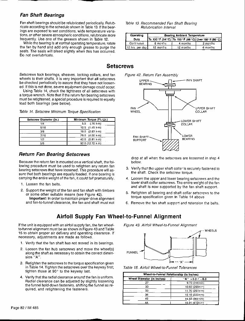
Fan Shaft Bearings
Fan shaft bearings should be relubricated periodically. Relub- Table 13. Recommended Fan Shaft Bearingricate according to the schedule shown in Table 13. If the bear- Relubrication Intervalings are exposed to wet conditions, wide temperature varia-tions, or other severe atmospheric conditions, relubricate more Operating Bearing Ambient Temperaturefrequently. Use one of the greases shown in Table 12. Duty TO 130” F (54” C) TO 150” F (66” C) 0ver150” F(66” C)
While the bearing is at normal operating temperature, rotate Continuous 6 months 4 months 2 months
the fan by hand and add only enough grease to purge the 12 hrs. per day 12 monlhs 12 months 6 months
seals. The seals will bleed slightlv when this has occurred.Do not overlubricate. - ‘
Setscrews
Setscrews lock bearings, sheaves, locking collars, and fan
wheels to their shafts. It is very important that all setscrews
be checked periodically to assure that they have not loosen-
ed. If this is not done, severe equipment damage could occur.Using Table 14, check the tightness of all setscrews with
a torque wrench. Note that if the return fan bearing setscrewsmust be retightened, a special procedure is required to equallyload both bearings (see below).
Table 14. Setscrew Minimum Torque Specification
Setscrew Oiameter (In.) Minimum Torque (Ft.-Lb.)
114 5.5 (.76 k-m)
5116 10.5 (1.45 k-m)
318 19.0 (2.63 k-m)
7118 29.0 (4.00 k-m)
112 42.0 (5.81 k-m)
5/8 92.0 (12.72 k-m)
Return Fan Bearing Setscrews
Because the return fan is mounted on a vertical shaft, the fol-lowing procedure must be used to retighten any return fanbearing setscrews that have loosened. This procedure will as-sure that both bearings are equally loaded. If one bearing iscarrying the entire weight of the fan, it could fail prematurely.
1. Loosen the fan belts.
2. Support the weight of the fan and fan shaft with timbersor some other suitable means (see Figure 42).
Important: In order to maintain proper drive alignmentand fan-to-funnel clearance, the fan and shaft must not
Figure 42. Return Fan Assembly
I IL 1
FAN /\ UPPER SHAFTWHEEL COLLAR
FAN SHAFTsuPPoRT
AFT
3.
4.
5.
6.
drop at all when the setscrews are loosened in step 4below.
Verify that the upper shaft collar is securely fastened tothe shaft. Check the setscrew torque.
Loosen the upper and lower bearing setscrews and thelower shaft collar setscrews. The entire weight of the fanand shaft is now supported by the fan shaft support.
Retighten all bearing and shaft collar setscrews to thetorque specification given in Table 14 above.
Remove the fan shaft support and retension the belts.
Airfoil Supply Fan Wheel-to-Funnel Alignment
If the unit is equipped with an airfoil supply fan, the fan wheel- Figure 43. Airfoil Wheel-to-Funnel Alignmentto-funnel alignment must be as shown in Figure 43 and Table15 to obtain proper air delivery and operating clearance. Ifnecessary, adjustments are made as follows.
II 4WHEELS1.
2.
3.
4.
Verify that the fan shaft has not moved in its bearings,
Loosen the fan hub setscrews and move the wheel(s)along the shaft as necessary to obtain the correct dimen-sion “A”.
‘*U
Retighten the setscrews to the torque specification given,, !,
in Table 14. Tighten the setscrews over the keyway first; Table 15. Airfoil Wheel-to-Funnel Tolerancestighten those at 90 to the keyway last,
~
WheeI-tc-Funnel Relationship fin Inches)Verify that the radial clearance around the fan is uniform.Radial clearance can be adjusted by slightly looseningthe funnel hold-down fasteners, shifting the funnel as re-quired, and retightening the fasteners.
36 13.10 (333mm)
40 14.50 (368rnm)
44 16.21 (412mm)
Page 82/ IM 485

Winterizing Water Coils
Coil freeze-up can be caused by several conditions; for ex- enough to guard against the coldest anticipated outdoor airample, air stratification, outdoor air damper failure, or preheat temperature.coil failure. The best way to ensure that coil freeze-up will not Note: Carefully read and follow the instructions for mixing
/ occur is to use an antifreeze solution that is concentrated the antifreeze solution used. Test the solution after it is mixed.
Service and Warranty ProcedureCompressor
Copeland Refrigeration Corporation has stocking wholesalerswho maintain a stock of replacement motor compressors andservice parts to serve refrigeration contractors and servicetechnicians as required.
When a motor compressor fails in warranty, the inoperativemotor compressor can be taken to any authorized Copelandwholesaler for an over-the-counter exchange or an advancereplacement may be obtained. Credit is issued on the returnedmotor compressor upon receipt and factory inspection of theinoperative motor compressor. In this transaction be cer-
tain that the motor compressor is definitely defective. If a motorcompressor is received from the field that tests satisfactorily,a service charge plus a transportation charge will be chargedagainst its original credit value.
On all out of warranty motor compressor failures, Copelandoffers the same field facilities for service or replacement asdescribed above. The credit issued on the returned motorcompressor will be determined by the repair charge estab-lished for that particular unit.
In-Warranty Return Material Procedure
Material other than compressors may not be returned exceptby permission of authorized factory service personnel ofMcQuay International at Minneapolis, Minnesota.
A “return goods” tag will be sent to be included with thereturned material. Enter the information as called for on thetag in order to expedite handling at our factories and issuanceof credits. All parts shall be returned to the factory designatedon the return goods tag, transportation charges prepaid.
The return of the part does not constitute an order for replace-ment. A purchase order for the replacement part must beentered through your nearest McQuay representative. The ordershould include the component’s part number and descriptionand the model and serial numbers of the unit involved.
If it is determined that the failure of the returned part is dueto faulty material or workmanship, credit will be issued on thecustomer’s purchase order.
Replacement Parts
When writing to McQuay for service or replacement parts, pro- to provide the number on the specific diagram. If replacementvide the model number, serial number, and G.O. number of parts are required, include the date of unit installation, thethe unit as stamped on the serial plate attached to the unit. date of failure, an explanation of the malfunction, and aFor questions regarding wiring diagrams, it will be necessary description of the replacement parts required.
IM 485 I Page 83
Product WarrantyMcQuay International, hereinafter referred to as the “Com-pany,” warrants that it will provide, at the Company’s option,either free replacement parts or free repair of component partsin the event any product manufactured by the Company andused in the United States proves defective in material orworkmanship within twelve (12) months from initial start-upor eighteen (18) months from the date shipped by the Com-pany, whichever comes first. For additional consid-eration, the Company warrants that for four (4) years follow-ing the initial warranty period it will provide, at the Company’soption, free replacement parts for the motor-compressor orfree replacement for any integral component of the motor-compressor which proves defective in material or workman-ship. For an additional consideration, the Company warrantsthat for nine (9) years following the initial warranty period itwill provide free replacement of the heat exchanger in gas-fired or oil-fired furnaces which proves defective in materialand workmanship. (Extended warranties for motor-compressors and heat exchangers are not applicable unlessseparately purchased.)
To obtain assistance under the parts warranty, extendedmotor-compressor warranty, or extended heat exchanger war-ranty, simply contact the selling agency. To obtain informa-tion or to gain factory help, contact McQuay International, War-ranty Claims Department, P.O. Box 1551, Minneapolis, MN55440; telephone (612) 553-5330.
This warranty constitutes the buyer’s sole remedy. It isgiven in lieu of all other warranties. There is no impliedwarranty of merchantability or fitness for a particular pur-
pose. In no event and under no circumstances shall theCompany be liable for incidental or consequentialdamages, whether the theory be breach of this or anyother warranty, negligence or strict tort.
This parts warranty and the optional extended warrantiesextend only to the original user. Of course, abuse, misuse,or alteration of the product in any manner voids the Com-pany’s warranty obligation. Neither the parts nor extendedwarranty obligates the Company to pay any labor or servicecosts for removing or replacing parts, or any shipping charges.Refrigerants, fluids, oils, and expendable items such as filtersare not covered by this warranty.
The extended warranties apply only to integral componentsof the motor-compressor or heat exchanger, not to refrigerantcontrols, electrical controls, or mechanical controls, or tofailures caused by failure of those controls.
Attached to this warranty is a requirement for equipmentcontaining motor-compressors and/or furnaces to report start-up information. The registration form accompanying the pro-duct must be completed and returned to the Company withinten (10) days of original equipment start-up. If that is not done,the date of shipment shall be presumed to be the date of start-up, and the warranty shall expire twelve (12) months from thatdate.
No person (including any agent, salesman, dealer ordistributor) has authority to extend the Company’s obligationbeyond the terms of this express warranty, or to state that theperformance of the product is other than that published bythe Company.
MCQUAY13600 Industrial Park Blvd., PO. Box 1551, Minneapolis, MN 55440 USA (612) 553-5330
@ Printed cm recycled paper containing at least 100/. post-consumer recycled material.