Embed Size (px)
Citation preview
Oval and Extended Oval Roofing Systems
Assembly and Operation Manual
Version of 2nd September 2007
1. General
The roofing system consists in the structure made of aluminium sections and the covered by the
combination of opaque tent canvas and transparent PVC foil.
The roofing structure can be moved using the traversing wheels provided. After being assembled and
erected on the intended place, the roofing must be fixed in position by means of anchors provided for the
purpose.
2. Basic Information
In the erection of the roofing system the following instructions should be observed.
Roofing system erection should be carried out by two persons, at least. A clean and dry horizontal flat area found close to the place of installation should be chosen for
assembling the roofing system, of the size sufficiently larger than the ground plan of the system. The weight
of assembled roofing system amounts to about 50 – 70 kg and can be carried to the place of its installation
by hand. It is recommended to cover the area of assembly with a suitable pad (paper, paperboard, a mat
or carpet) to protect roofing components from scratching in the course of assembly.
Recommended tools: a rubber mallet and a round file.
Don‘t erect or handle the roofing system in windy weather.
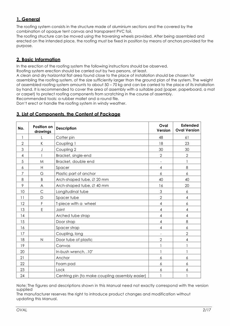
3. List of Components, the Content of Package
No.
Position on drawings
v obrázcích
Description
Oval Version
Extended Oval Version
1 L Cotter pin 48 61 2 K Coupling 1 18 23 3 J Coupling 2 30 30 4 I Bracket, single-end 2 2 5 M Bracket, double end - 1 6 H Spacer 4 8 7 G Plastic part of anchor 6 6 8 B Arch-shaped tube, ∅ 20 mm 40 40 9 A Arch-shaped tube, ∅ 40 mm 16 20
10 C Longitudinal tube 3 6 11 D Spacer tube 2 4 12 F T-piece with a wheel 4 6 13 E Joint 4 4 14 Arched tube strap 4 4 15 Door strap 4 8 16 Spacer strap 4 6 17 Coupling, long - 2 18 N Door tube of plastic 2 4 19 Canvas 1 1 20 In-bush wrench, .10" 1 1 21 Anchor 6 6 22 Foam pad 6 6 23 Lock 6 6 24 Centring pin (to make coupling assembly easier) 1 1
Note: The figures and descriptions shown in this Manual need not exactly correspond with the version supplied
The manufacturer reserves the right to introduce product changes and modification without
updating this Manual. OVAL 2/17

4. Roofing Erection
Step 1: Preparing the load-bearing arch halves
Take (always) two arches (A)(ø 40mm), two cotter pins (L) and a coupling (K). Insert the coupling in either arch
end and secure it in position by a cotter pin. To make the installation of the cotter pins in the holes in the coupling and in the
arch you can use the centring pin supplied. Slide the end of the other arch on the coupling and secure the connection
with other cotter pin (L). Both cotter pins should be inserted from the same side of the coupling with the pin noses facing the
arch centre (see Fig. 1). Using the same steps, assemble the four half-arches required for the oval roofing or six
half-arches for the extended oval roofing.
Figure 1
Step 2: Assembling the load-bearing arches
Assemble two main load-bearing arches from the four preassembled arch halves. Put the pair of arch
halves on the ground to form a half-circle (see Fig. 2) with the noses of cotter pins inserted in the
couplings facing upwards. At this stage the straps should be slid on the tubes with the clasps, which will
later secure the lifted hemispheres of the roofing system (see Fig. A in Part 10 – Illustrated Supplement).
The strap shorter ends with clasp should face downwards, while the longer ends with clasps should be
turned upwards. Now the straps should be slid on the arch tubes from the centre of the intended
semicircle to the first connecting cotter pin that has been already installed. In the same way as in Step 1
hereof connect the two semicircles to form a whole, with the exception that the single-end bracket (I) has
to be installed in the centre, before sliding the other arch half on the coupling. The bracket should be put
on with its aluminium part is on the inner side of the arch. Its tube with the hole for the cotter pin should face upwards
In case that the extended oval roofing is to be assembled, the remaining two halves of load-bearing arches
should be put together in the same way, but using the double-end bracket and without straps.
OVAL 3/17
A – Arch ∅∅∅∅ 40 mm L – Cotter pin K - Coupling
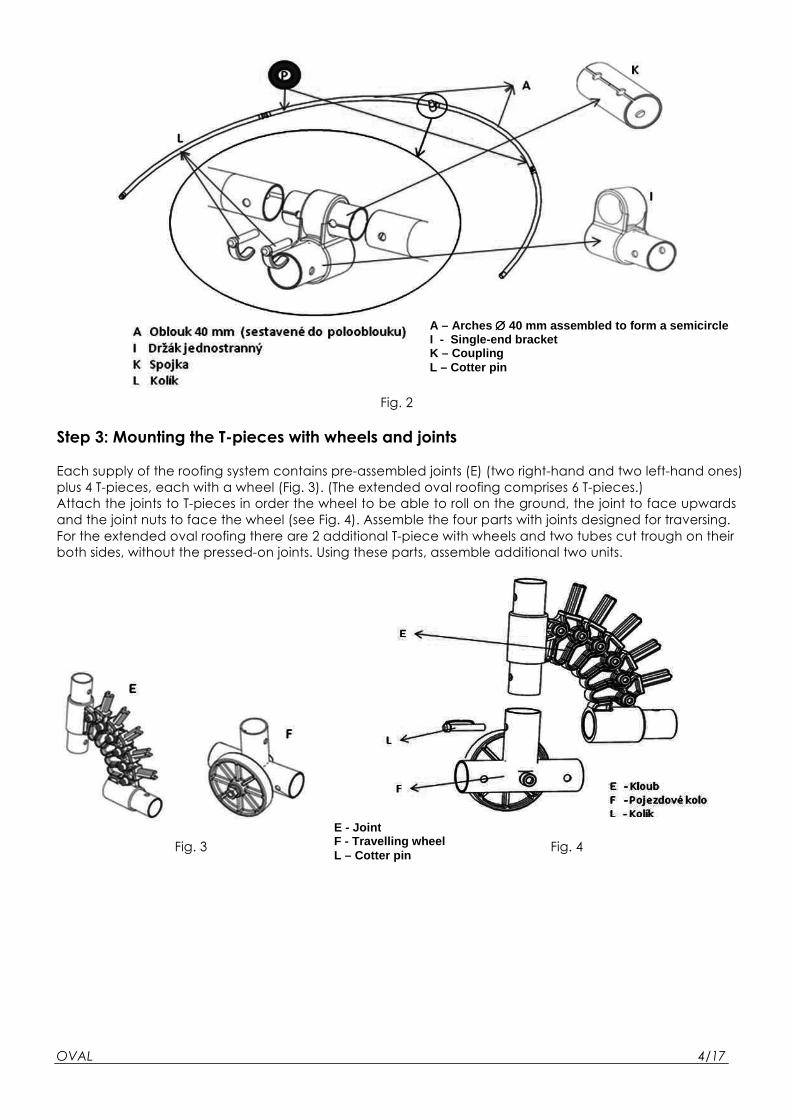
Fig. 2
Step 3: Mounting the T-pieces with wheels and joints
Each supply of the roofing system contains pre-assembled joints (E) (two right-hand and two left-hand ones)
plus 4 T-pieces, each with a wheel (Fig. 3). (The extended oval roofing comprises 6 T-pieces.)
Attach the joints to T-pieces in order the wheel to be able to roll on the ground, the joint to face upwards
and the joint nuts to face the wheel (see Fig. 4). Assemble the four parts with joints designed for traversing.
For the extended oval roofing there are 2 additional T-piece with wheels and two tubes cut trough on their
both sides, without the pressed-on joints. Using these parts, assemble additional two units.
Fig. 3 Fig. 4
OVAL 4/17
A – Arches ∅∅∅∅ 40 mm assembled to form a semicircle I - Single-end bracket K – Coupling L – Cotter pin
E - Joint F - Travelling wheel L – Cotter pin
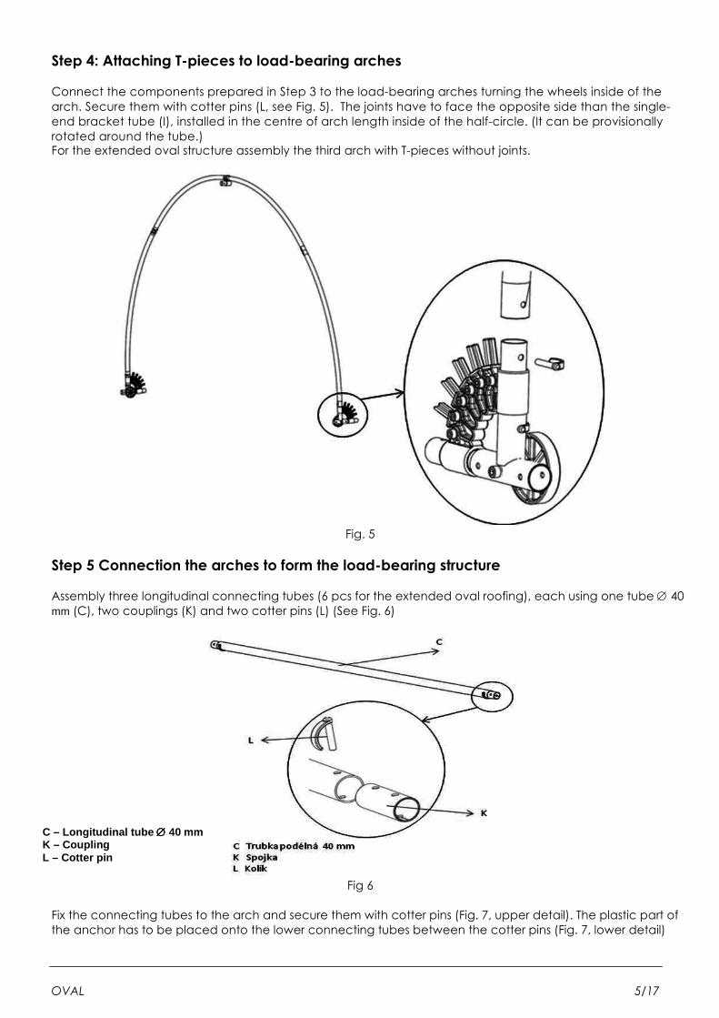
Step 4: Attaching T-pieces to load-bearing arches
Connect the components prepared in Step 3 to the load-bearing arches turning the wheels inside of the
arch. Secure them with cotter pins (L, see Fig. 5). The joints have to face the opposite side than the single-
end bracket tube (I), installed in the centre of arch length inside of the half-circle. (It can be provisionally
rotated around the tube.) For the extended oval structure assembly the third arch with T-pieces without joints.
Fig. 5
Step 5 Connection the arches to form the load-bearing structure
Assembly three longitudinal connecting tubes (6 pcs for the extended oval roofing), each using one tube ∅ 40 mm (C), two couplings (K) and two cotter pins (L) (See Fig. 6)
Fig 6
Fix the connecting tubes to the arch and secure them with cotter pins (Fig. 7, upper detail). The plastic part of
the anchor has to be placed onto the lower connecting tubes between the cotter pins (Fig. 7, lower detail)
OVAL 5/17
C – Longitudinal tube ∅∅∅∅ 40 mm K – Coupling L – Cotter pin
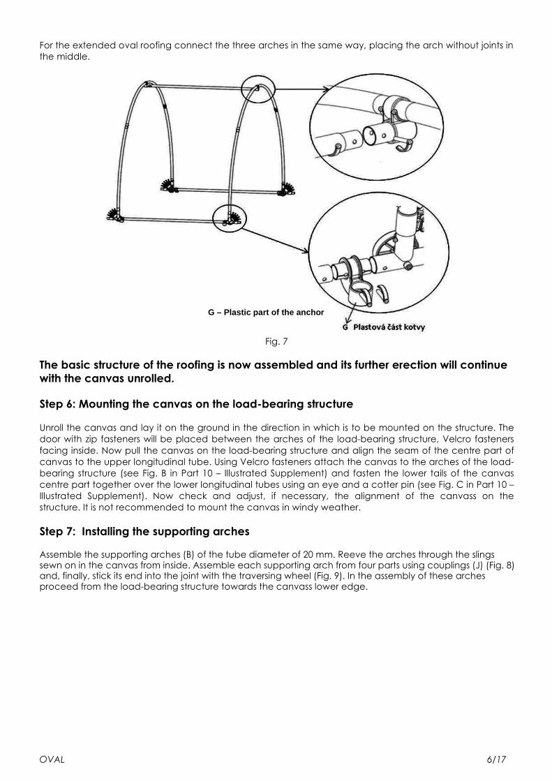
For the extended oval roofing connect the three arches in the same way, placing the arch without joints in
the middle.
Fig. 7
The basic structure of the roofing is now assembled and its further erection will continue with the canvas unrolled.
Step 6: Mounting the canvas on the load-bearing structure
Unroll the canvas and lay it on the ground in the direction in which is to be mounted on the structure. The
door with zip fasteners will be placed between the arches of the load-bearing structure, Velcro fasteners
facing inside. Now pull the canvas on the load-bearing structure and align the seam of the centre part of
canvas to the upper longitudinal tube. Using Velcro fasteners attach the canvas to the arches of the load-
bearing structure (see Fig. B in Part 10 – Illustrated Supplement) and fasten the lower tails of the canvas
centre part together over the lower longitudinal tubes using an eye and a cotter pin (see Fig. C in Part 10 –
Illustrated Supplement). Now check and adjust, if necessary, the alignment of the canvass on the
structure. It is not recommended to mount the canvas in windy weather.
Step 7: Installing the supporting arches
Assemble the supporting arches (B) of the tube diameter of 20 mm. Reeve the arches through the slings sewn on in the canvas from inside. Assemble each supporting arch from four parts using couplings (J) (Fig. 8) and, finally, stick its end into the joint with the traversing wheel (Fig. 9). In the assembly of these arches proceed from the load-bearing structure towards the canvass lower edge.
OVAL 6/17
G – Plastic part of the anchor

Fig. 8
Fig. 9
OVAL 7/17
B – Arch ∅∅∅∅ 20 mm J - Coupling
A – Arch ∅∅∅∅ 40 mm B – Arch ∅∅∅∅ 20 mm C – Longitudinal connecting tube ∅∅∅∅ 40 mm E – Joint F – Traversing wheel G – Plastic part of the anchor
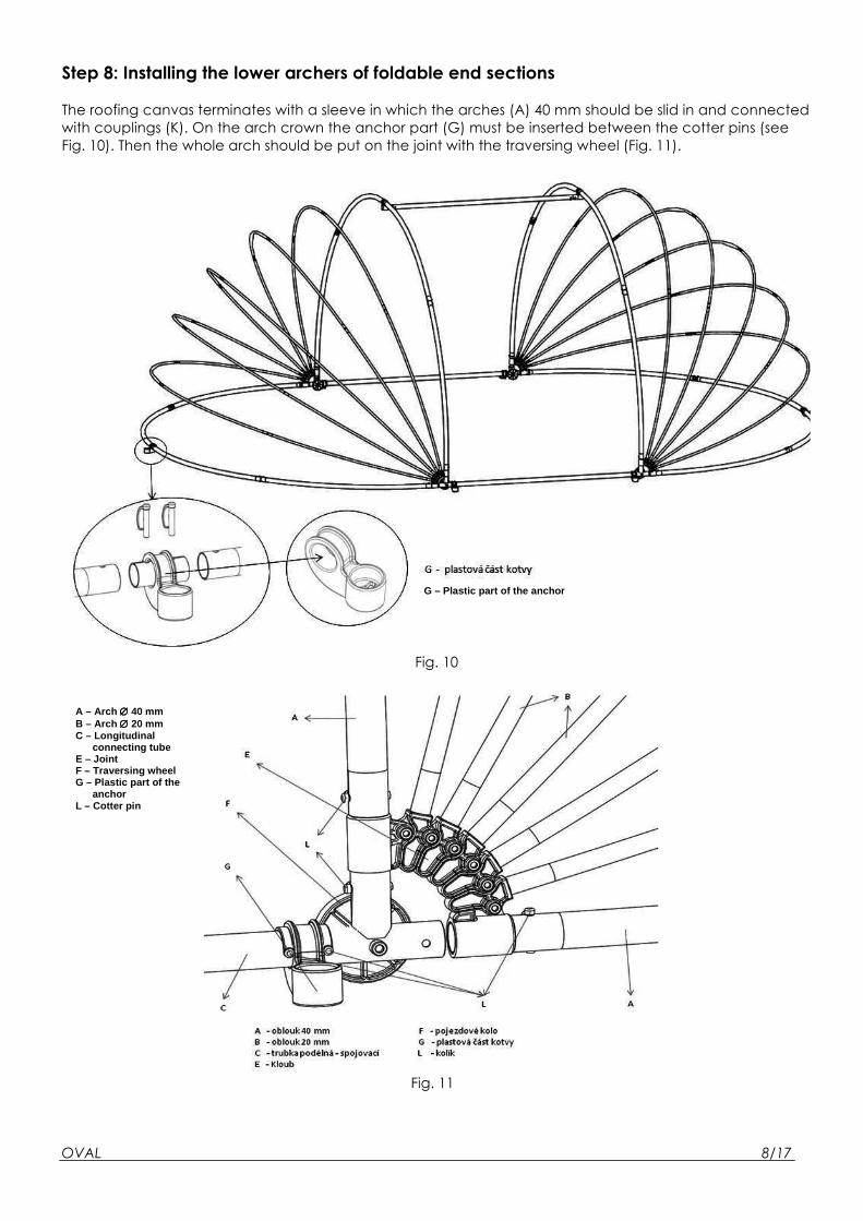
Step 8: Installing the lower archers of foldable end sections
The roofing canvas terminates with a sleeve in which the arches (A) 40 mm should be slid in and connected
with couplings (K). On the arch crown the anchor part (G) must be inserted between the cotter pins (see
Fig. 10). Then the whole arch should be put on the joint with the traversing wheel (Fig. 11).
Fig. 10
Fig. 11
OVAL 8/17
G – Plastic part of the anchor
A – Arch ∅∅∅∅ 40 mm B – Arch ∅∅∅∅ 20 mm C – Longitudinal connecting tube E – Joint F – Traversing wheel G – Plastic part of the anchor L – Cotter pin
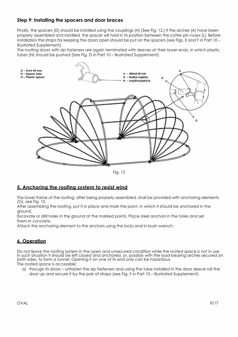
Step 9: Installing the spacers and door braces
Finally, the spacers (D) should be installed using the couplings (H) (See Fig. 12.) If the arches (A) have been
properly assembled and installed, the spacer will hold in its position between the cotter pin noses (L). Before
installation the straps for keeping the doors open should be put on the spacers (see Figs. E and F in Part 10 –
Illustrated Supplement).
The roofing doors with zip fasteners are again terminated with sleeves at their lower ends, in which plastic
tubes (N) should be pushed (See Fig. D in Part 10 – Illustrated Supplement).
Fig. 12
5. Anchoring the roofing system to resist wind
The lower frame of the roofing, after being properly assembled, shall be provided with anchoring elements (G), see Fig. 10.
After assembling the roofing, put it in place and mark the point. in which it should be anchored in the
ground.
Excavate or drill holes in the ground at the marked points. Place steel anchors in the holes and set
them in concrete.
Attach the anchoring element to the anchors using the locks and in-bush wrench.
6. Operation
Do not leave the roofing system in the open and unsecured condition while the roofed space is not in use. In such situation it should be left closed and anchored, or, possibly with the load-bearing arches secured on both sides, to form a tunnel. Opening it on one of its end only can be hazardous. The roofed space is accessible:
a) through its doors – unfasten the zip fasteners and using the tube installed in the door sleeve roll the
door up and secure it by the pair of straps (see Fig. F in Part 10 – Illustrated Supplement);
OVAL 9/17
A – Arch 40 mm D – Spacer tube H – Plastic spacer
b) through its spherical ends – lift the spherical sections up to their upper position (either at one or both ends of the
roofing) and secure them by means of the pair of straps provided (see Figs. G and H in Part 10 –
Illustrated Supplement).
If the roofed space is occupied, let, at least, either door open to provide for the required air exchange.
After leaving the roofed space, shut the door by means of zip fasteners, or lower the arches of spherical
sections down to their low position and secure them against wind by anchors.
If required, the roofing system can be detached from its anchoring elements and moved away on its
travelling wheels.
Before leaving the roofing make always sure that it is properly closed and anchored in the ground.
7. Safety rules
• Use the roofing only for the purpose, which it is intended for, i.e. to roof a pool, an outdoor sitting
area, a car, etc.
• This roofing does not constitute any safety system preventing any persons or animals from accessing the
pool area. Both the roofing manufacturer and seller shall not be responsible for any personal injury or
damage to property if this warning has not been taken into account.
• The assembled roofing must be firmly anchored in the ground by means of the anchors provided
(see Chapter 5 hereof).
• At the time of bathing in the roofed pool the roofing door should be left open, otherwise the
temperature in the roofed space could increase to a relatively high level, which could cause health
problems to certain persons staying in the roofed area.
• After opening/closing the door and/or end sections the operator shall secure the door and/or the
lifted/closed door and arches in the open or closed position, as appropriate.
• It is strictly forbidden to use any source of open flame in the roofed area because the risk of fire.
• If the roofing is used for protecting a car from weather effects, the car engine must not be started
under the closed roofing. Before starting the engine lift up and secure the supporting arches on the
side of car exhaust.
• In windy weather it is essential to keep the roofing in its closed and secured condition.
• It is extremely hazardous to leave the roofing open at its one side, when air has no way out and can
destroy the roofing, with the resulting risk of damage to property or personal injury.
• It is forbidden to open the roofing in strong winds. It could be very hazardous.
• Do not load the parts of the roofing structure excessively. Do not suspend any items on the structure.
The roofing structure is not designed to stand any movement of persons on it, climbing, etc., and
could collapse.
8. Maintenance
Covering materials should be kept clean. Lukewarm water and mild detergent should be used for the purpose. Do not use any cleaning agents containing/releasing chlorine.
It is recommended to lubricate the rotational parts (joints, wheel pins, etc.) with silicone lubricant both
before the start and after the end of the season.
If the roofing is left outdoor in winter, snow, if any, should be regularly removed from the roofing to protect
its structure from overloading.
Do not handle the roofing elements in winter, as its plastic materials get brittle and become more liable to
damage at low temperatures.
If it is intended to store the roofing for the winter period, it should be carefully disassembled and stored in
a dry cold place to protect it from damage.
The manufacturer shall not be responsible for any possible damage caused by any non-observance of the
instructions contained herein.
OVAL 10/17

9. Warranty, service, spare parts
The conditions of granted warranty are specified in the warranty certificate of the seller. Direct, please, any your questions and requests for service and spare parts to your supplier of this product.
It is highly recommended to employ only the genuine spare parts for any repair/maintenance of the
product.
OVAL 11/17
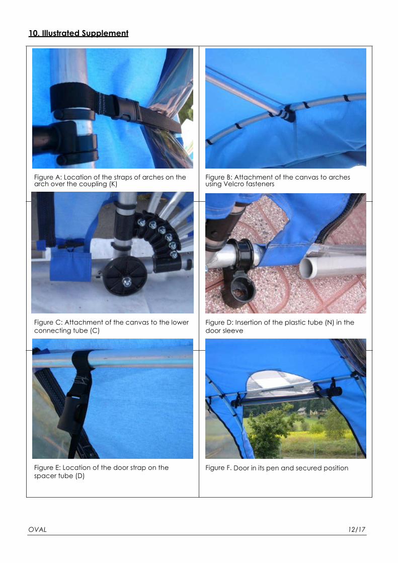
10. Illustrated Supplement
Figure A: Location of the straps of arches on the arch over the coupling (K)
Figure C: Attachment of the canvas to the lower
connecting tube (C)
Figure E: Location of the door strap on the
spacer tube (D)
Figure B: Attachment of the canvas to arches using Velcro fasteners
Figure D: Insertion of the plastic tube (N) in the
door sleeve
Figure F. Door in its pen and secured position
OVAL 12/17

Figure G: Fixing the load-bearing arches (A) In the open position by straps.
Figure I: Roofing anchor system - from the left:
Anchor to be set in concrete, foam pad, plastic
part of anchor, in-bush wrench
Figure H: Detail of the strap in fixing the arches in the open position
OVAL 13/17

11. Indicative dimensions of the OVAL roofing and the layout of anchors Frame type: AZURO OVAL 4,1 x 6,2 m
OVAL 14/17

Frame type: AZURO OVAL 4,9 x 7,0 m
OVAL 15/17

Extended frame type: AZURO OVAL 4,1 x 8,1 m
OVAL 16/17

Extended frame type: AZURO OVAL 4,9 x 8,9 m
OVAL 17/17