Embed Size (px)
Citation preview

Design and Implementation of Computer Science Virtualized Lab Environment
at SUNYIT
Ronny L. Bull
A Master’s Thesis
Submitted to theDepartment of Computer & Information Science
State University of New York Institute of Technologyin Partial Fulfillment of the
Requirements for theDegree of
Master of Science
Utica, New YorkSpring 2012

Design and Implementation of Computer Science Virtualized Lab Environment
at SUNYIT
Except where reference is made to the work of others, the work described in this Master’s thesisis my own or was done in collaboration with my advisory committee. Further,
the content of this Master’s thesis is truthful in regards to my own workand the portrayal of others’ work. This Master’s thesis does not
include proprietary or classified information.
Ronny L. Bull
Certificate of Approval:
Dr. Geethapriya ThamilarasuAssistant ProfessorDepartment of Computer Science
Dr. John MarshAssociate ProfessorDepartment of Computer Science
Dr. Saumendra SenguptaProfessorDepartment of Computer Science

Design and Implementation of Computer Science Virtualized Lab Environment
at SUNYIT
Ronny L. Bull
Permission is granted to the State University of New York Institute of Technologyto make copies of this Master’s thesis at its discretion, upon the request of
individuals or institutions and at their expense.The author reserves all publication rights.
Ronny L. Bull
Spring 2012
iii

Vita
Ronny L. Bull started his career in computing by completing multiple certification training
programs in 2000 and 2001 at North East Technical Institute in South Portland Maine where he
also earned various ComptIA, Microsoft, and Cisco certifications. He has worked in the fields of
computer networking and systems administration since 2002 as either a Systems Administrator,
Engineer, IT Manager, or IT Consultant for various companies throughout New York state. Ronny
received an Associate’s degree in Computer Networking from Herkimer County Community College
in 2006 where he graduated with honors. In 2009 he began attending SUNYIT enrolled in the
Computer Science B.S. program, and received his Bachelor’s degree promptly in 2010. Ronny
graduated Magna Cum Laude, and also received the Outstanding Student Award for the B.S.
Computer & Information Science program.
While working full time on his Master’s degree in Computer Science at SUNYIT, Ronny is
currently employed as a student administrator for the Computer Science department. Additionally
he works as an adjunct professor at Mohawk Valley Community College, and is a part time engineer
for M.A. Polce Consulting in Rome New York. Ronny also runs his own consulting company called
Adirondack IT Solutions, LLC which provides IT consulting and application development services
for clients in Central and Northern New York.
iv

Abstract
With growing student interest in the SUNYIT Network Computer Security (NCS) and Voice
over IP (VoIP) communications courses, new and innovative ways need to be employed in order to
keep up with the increasing enrollment. The traditional laboratory setups are quickly becoming
outdated, and bottlenecks in the students capability to learn are forming due to increasing class
sizes. Under the previous settings students were required to share physical hardware in order to gain
hands-on experience, inevitably causing some students to have more hands-on time than others.
A centralized virtualization approach has been proposed and implemented in order to allow the
courses to scale with enrollment, as well as give each student an equal opportunity to gain hands-on
experience.
v

Acknowledgments
The current work of this thesis began with discussions during the Spring 2011 semester
between the author and Nick Merante concerning the need for a laboratory environment solution
that would support the rapidly increasing enrollment in the Network Computer Security program.
Though the system discussed in this thesis was designed and implemented by the author, there
were others that have contributed significantly throughout the course of it’s development by either
helping to administrate the system or by testing and deploying virtual machines for students.
Special thanks go out to the following individuals for their assistance:
• Dr. Geethapriya Thamailarasu - inception to current
• Dr. John Marsh - inception to current
• Dr. Saumendra Sengupta - Fall 2011
• Dr. Scott Spetka - Fall 2011
• Nick Merante - inception to current
• Alex Stuart - inception to current
• Mohammed Haque - inception to current
Many thanks go out to all the people that have helped make this project happen, not just those
listed as contributors. To the family of the author, thank you for all of your support.
vi

Style manual or journal used Journal of Approximation Theory (together with the style known
as “sunyitms”). Bibliography follows van Leunen’s A Handbook for Scholars.
Computer software used The document preparation package TEX (specifically LATEX2e) together
with the style-file sunyitms.sty.
vii

Table of Contents
List of Figures xi
List of Tables xiv
1 Introduction 1
1.1 General Overview . . . . . . . . . . . . . . . . . . . . . . . . . . . . . . . . . . . . . . 1
1.2 Virtualization Basics . . . . . . . . . . . . . . . . . . . . . . . . . . . . . . . . . . . . 2
1.3 The Hypervisor . . . . . . . . . . . . . . . . . . . . . . . . . . . . . . . . . . . . . . . 4
1.4 Hardware Virtualization vs Para-Virtualization . . . . . . . . . . . . . . . . . . . . . 7
2 Related Work 10
2.1 Centralized Approaches . . . . . . . . . . . . . . . . . . . . . . . . . . . . . . . . . . 10
2.1.1 Iowa State University - Xen Worlds . . . . . . . . . . . . . . . . . . . . . . . 10
2.1.2 Michigan Technological University - VMWare Lab Manager . . . . . . . . . . 11
2.1.3 University of South Flordia Lakeland - SOFTICE . . . . . . . . . . . . . . . . 12
2.2 Decentralized Approaches . . . . . . . . . . . . . . . . . . . . . . . . . . . . . . . . . 12
2.2.1 Hypervisor and Virtual Machines Installed on Student Hardware . . . . . . . 13
2.2.2 Hypervisor and Virtual Machines Provided on Laboratory Hardware . . . . . 13
viii

3 The SUNYIT CS Virtualized Lab Environment 14
3.1 Project Requirements . . . . . . . . . . . . . . . . . . . . . . . . . . . . . . . . . . . 14
3.2 Choice of Hypervisor . . . . . . . . . . . . . . . . . . . . . . . . . . . . . . . . . . . . 14
3.3 Server Hardware Specifications . . . . . . . . . . . . . . . . . . . . . . . . . . . . . . 15
3.4 Installation of Xen Cloud Platform . . . . . . . . . . . . . . . . . . . . . . . . . . . . 16
3.5 Subnetting & Virtual LANs . . . . . . . . . . . . . . . . . . . . . . . . . . . . . . . . 19
3.5.1 Subnetting . . . . . . . . . . . . . . . . . . . . . . . . . . . . . . . . . . . . . 19
3.5.2 Virtual LANs . . . . . . . . . . . . . . . . . . . . . . . . . . . . . . . . . . . . 20
3.6 Networking Configuration . . . . . . . . . . . . . . . . . . . . . . . . . . . . . . . . . 21
3.7 Centralized System Admnistration . . . . . . . . . . . . . . . . . . . . . . . . . . . . 23
3.8 Bugs, Issues, Hacks and Fixes . . . . . . . . . . . . . . . . . . . . . . . . . . . . . . . 25
3.9 User Access and Authentication . . . . . . . . . . . . . . . . . . . . . . . . . . . . . . 26
3.10 Server Monitoring . . . . . . . . . . . . . . . . . . . . . . . . . . . . . . . . . . . . . 28
3.10.1 Graph Data . . . . . . . . . . . . . . . . . . . . . . . . . . . . . . . . . . . . . 29
4 Implementations 34
4.1 Computer Science Department . . . . . . . . . . . . . . . . . . . . . . . . . . . . . . 35
4.2 Network Computer Security Laboratories . . . . . . . . . . . . . . . . . . . . . . . . 35
4.3 Asterisk Voice Over IP (VoIP) Laboratories . . . . . . . . . . . . . . . . . . . . . . . 40
4.4 Linux Systems Administration Laboratories . . . . . . . . . . . . . . . . . . . . . . . 45
4.5 Projects and Independent Studies . . . . . . . . . . . . . . . . . . . . . . . . . . . . . 46
ix

5 Discussion 48
5.1 SUNYIT CS VLE Issues . . . . . . . . . . . . . . . . . . . . . . . . . . . . . . . . . . 48
5.2 SUNYIT CS VLE Improvements . . . . . . . . . . . . . . . . . . . . . . . . . . . . . 49
5.3 Network Attached Storage Options . . . . . . . . . . . . . . . . . . . . . . . . . . . . 49
5.4 Metasploitable Ubuntu Virtual Machine Migration . . . . . . . . . . . . . . . . . . . 50
6 Conclusion 52
Bibliography 53
Appendices 56
A NCS Virtual Lab Manual 57
B TEL500 Virtual Lab Manual 62
B.1 Getting Started . . . . . . . . . . . . . . . . . . . . . . . . . . . . . . . . . . . . . . . 62
B.2 Accessing an Asterisk VM via SSH . . . . . . . . . . . . . . . . . . . . . . . . . . . . 67
B.3 Intial Configuration of Virtual Machine . . . . . . . . . . . . . . . . . . . . . . . . . 72
B.4 Configuring IPTables Firewall . . . . . . . . . . . . . . . . . . . . . . . . . . . . . . . 81
B.5 Configuring SIP Extensions . . . . . . . . . . . . . . . . . . . . . . . . . . . . . . . . 86
B.6 Configuring an IAX2 Trunk Connection . . . . . . . . . . . . . . . . . . . . . . . . . 91
x
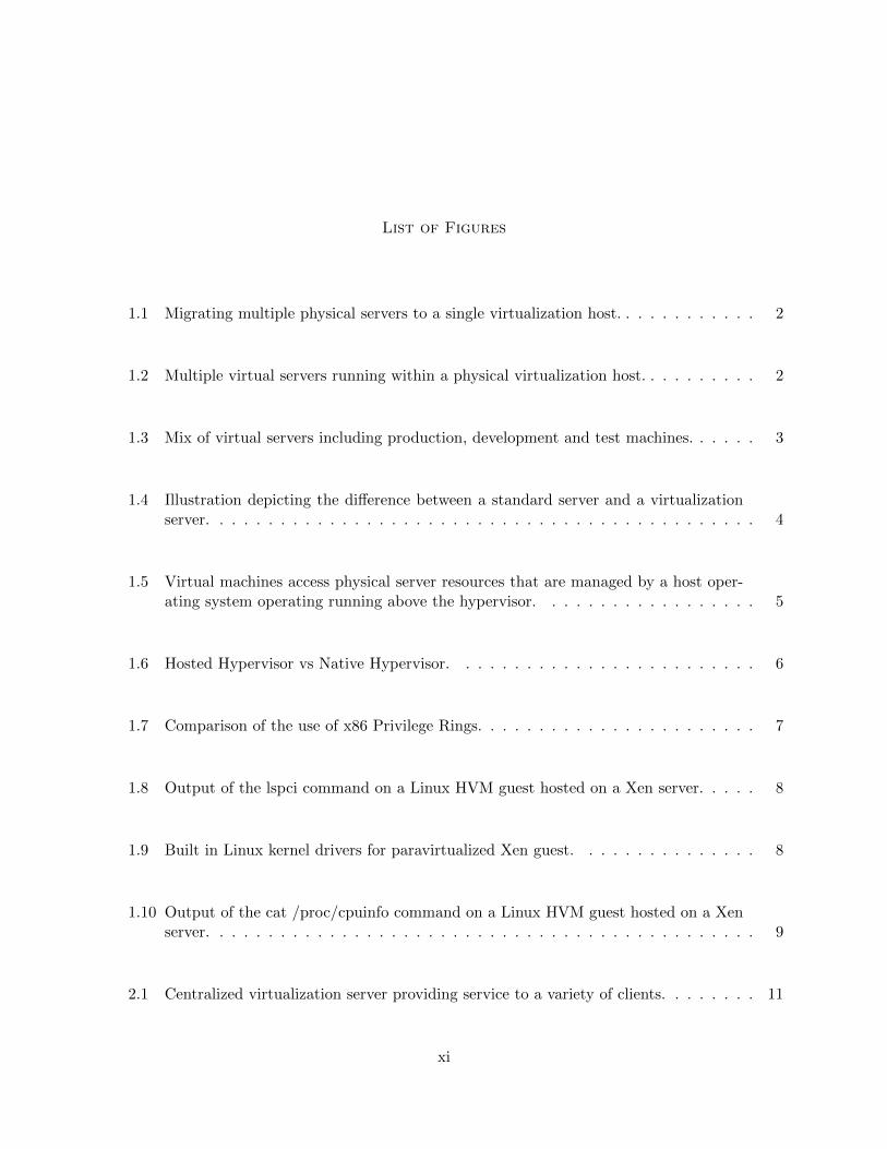
List of Figures
1.1 Migrating multiple physical servers to a single virtualization host. . . . . . . . . . . . 2
1.2 Multiple virtual servers running within a physical virtualization host. . . . . . . . . . 2
1.3 Mix of virtual servers including production, development and test machines. . . . . . 3
1.4 Illustration depicting the difference between a standard server and a virtualizationserver. . . . . . . . . . . . . . . . . . . . . . . . . . . . . . . . . . . . . . . . . . . . . 4
1.5 Virtual machines access physical server resources that are managed by a host oper-ating system operating running above the hypervisor. . . . . . . . . . . . . . . . . . 5
1.6 Hosted Hypervisor vs Native Hypervisor. . . . . . . . . . . . . . . . . . . . . . . . . 6
1.7 Comparison of the use of x86 Privilege Rings. . . . . . . . . . . . . . . . . . . . . . . 7
1.8 Output of the lspci command on a Linux HVM guest hosted on a Xen server. . . . . 8
1.9 Built in Linux kernel drivers for paravirtualized Xen guest. . . . . . . . . . . . . . . 8
1.10 Output of the cat /proc/cpuinfo command on a Linux HVM guest hosted on a Xenserver. . . . . . . . . . . . . . . . . . . . . . . . . . . . . . . . . . . . . . . . . . . . . 9
2.1 Centralized virtualization server providing service to a variety of clients. . . . . . . . 11
xi

2.2 Individual machines hosting their own virtual machine clients. . . . . . . . . . . . . . 12
3.1 xsconsole management tool viewed from a remote terminal via SSH. . . . . . . . . . 17
3.2 Abstraction of typical virtual LAN usage on a SUNYIT CS VLE server. . . . . . . . 22
3.3 Citrix XenCenter running on Windows XP. . . . . . . . . . . . . . . . . . . . . . . . 24
3.4 The open source OpenXenManager utility running on Gentoo Linux. . . . . . . . . . 25
3.5 Abstraction of how users access their virtual machines via a web browser. . . . . . . 27
3.6 Round Trip Times over one week for Xen2. . . . . . . . . . . . . . . . . . . . . . . . 29
3.7 Round Trip Times over one month for Xen2. . . . . . . . . . . . . . . . . . . . . . . 30
3.8 Disk space for / on Xen2 over one month. . . . . . . . . . . . . . . . . . . . . . . . . 30
3.9 XenStore disk space on Xen2 over one month. . . . . . . . . . . . . . . . . . . . . . . 31
3.10 Load Average(1 min) for Xen2 over one month. . . . . . . . . . . . . . . . . . . . . . 32
3.11 Load Average(5 min) for Xen2 over one month. . . . . . . . . . . . . . . . . . . . . . 32
3.12 Load Average(15 min) for Xen2 over one month. . . . . . . . . . . . . . . . . . . . . 32
4.1 The evolution and layout of the SUNYIT CS Virtualized Lab Environment (June2011 - May 2012). . . . . . . . . . . . . . . . . . . . . . . . . . . . . . . . . . . . . . 34
xii

4.2 Typical group setup under the original Network Computer Security physical labora-tory setting. . . . . . . . . . . . . . . . . . . . . . . . . . . . . . . . . . . . . . . . . . 36
4.3 Five groups of physical machines isolated from each other and the external world inthe original laboratory environment. . . . . . . . . . . . . . . . . . . . . . . . . . . . 37
4.4 Students access their virtual machines from a remote workstation via a web browserconnected to http://xen1-web.cs.sunyit.edu. . . . . . . . . . . . . . . . . . . . . . . . 38
4.5 Student virtual machines are isolated to the NCS DarkNet VLAN where each studentis assigned a subnet to use for their virtual machines. . . . . . . . . . . . . . . . . . . 39
4.6 Original TEL500 Voice Communications laboratory setup. . . . . . . . . . . . . . . . 41
4.7 Basic overview of the virtual laboratory gateway setup. . . . . . . . . . . . . . . . . 43
4.8 Laboratory VLAN access restrictions. . . . . . . . . . . . . . . . . . . . . . . . . . . 44
4.9 Student virtual machines connecting to a trunking server over the IAX2 protocol togain PSTN access via FXO cards. . . . . . . . . . . . . . . . . . . . . . . . . . . . . . 45
xiii

List of Tables
3.1 SUNYIT Computer Science network subnets available to the VLE servers. . . . . . . 20
3.2 SUNYIT Computer Science VLAN tags and their associated subnets. . . . . . . . . 21
3.3 Nagios monitoring of SUNYIT CS VLE servers. . . . . . . . . . . . . . . . . . . . . . 28
xiv

Chapter 1
Introduction
1.1 General Overview
The evolution of virtualization technology has made a huge impact on the world of comput-
ing. In the business world, many companies are migrating towards server consolidation techniques
that harness the power of virtualization to save space and energy, cut costs, reduce downtime, and
lower administrative overhead [1, 2]. With today’s advances in computer technology, entire rooms
of servers can be consolidated down to a single rack of powerful machines that are set up in a
virtualization cluster while providing an increased level of service than what was previously relied
upon. This technology has also proven useful in education where virtualization can be used as an
adjunct to current laboratory setups [7, 8, 13, 14, 23]. Entire laboratories can also be virtualized
freeing up physical space and funding for other uses [4, 6, 12, 15, 17, 18, 19, 20, 16, 22, 24]. The
SUNYIT CS Virtualized Lab Environment (VLE) is a centralized virtualization[4] approach that
was setup with these goals in mind, as well as the major goal of empowering students by giving
them convenient access to the resources they need to succeed.
The rest of this chapter provides insight into the fundamentals of virtualization. Chapter 2
explores some related virtualization laboratory implementations at other universities as well as the
differences between centralized and decentralized virtualization topologies. Chapter 3 describes the
design of the SUNYIT Computer Science Virtualized Lab Environment, and chapter 4 goes into
detail about each of the specific implementations of the SUNYIT CS VLE. Chapter 5 provides
an overview of some of the issues that were encountered in the design phase as well as some
considerations for future enhancement of the system. The thesis is concluded in chapter 6, and
some of the laboratory exercises that utilize the SUNYIT CS VLE can be found in the appendix
section.
1

1.2 Virtualization Basics
The basic concept of virtualization is to use a single physical server with an abundance
of resources to host multiple virtual servers. For instance a data center that has multiple aging
physical servers each hosting a separate service such as email, web, user files, applications, remote
access, etc.. can consolidate the physical hardware down to a single powerful server that can host
each of the previously physical servers virtually in an isolated environment from the others (see
figure 1.1). Each virtual server would then have its own personal slice of the available resources
from the physical host machine as shown in figure 1.2.
Figure 1.1: Migrating multiple physical servers to a single virtualization host.
Figure 1.2: Multiple virtual servers running within a physical virtualization host.
2

With the migration to a virtual data center also comes the benefits of lower administrative
overhead and higher reliability of services. Most of the virtualization products available today
provide the capability to centrally manage virtual machines via a virtual machine manager or an
API. Virtual machines are also easily backed up by a variety of methods with the standard being
the use of snapshots or virtual machine exports to a network storage device. A snapshot allows
an administrator to take a quick image of a virtual machine at a certain point in time. Snapshots
are usually small in size since they only contain information about what has changed since the
last snapshot. However, a major benefit is that they can be performed while a virtual machine is
on-line. They are very useful as a quick backup tool when making changes to a system so that an
administrator can quickly roll the system back to a previous state if necessary. Virtual machines
can also usually be exported in their entirety, providing a way to perform a full backup that can
be re-imported into the virtualization system at any time if needed to restore the machine.
A common use for virtualization is as a sandbox[19] environment to test servers before they are
put into production use. The benefit of using virtualization is that development and production
servers can be hosted on the same physical machine without ever affecting each other due to the
isolation provided by the host OS (see figure 1.3). Updates and patches can be deployed on a cloned
copy of a production server to see if they may have any adverse affects before they are pushed live,
preventing any downtime that may have occurred as a result.
Figure 1.3: Mix of virtual servers including production, development and test machines.
3

1.3 The Hypervisor
Server virtualization is made possible by the use of a hypervisor which is the basic abstrac-
tion layer of software that sits directly on the hardware below any operating systems (see figure
1.4). It is responsible for CPU scheduling and memory partitioning of the various virtual machines
running on the physical hardware. It not only abstracts the physical hardware for the virtual ma-
chines, but it also controls the execution of virtual machines as they share the common processing
environment. Unlike a regular operating system, the hypervisor has no knowledge of networking,
external storage devices, video, or any other common I/O functions.
Figure 1.4: Illustration depicting the difference between a standard server and a virtualizationserver.
The virtual machines that run on top of the hypervisor are broken up into two different cate-
gories: host and guest (see figure 1.5). The host operating system is a privileged virtual machine
that has special rights to access physical I/O resources as well as interact with the other virtual
machines running on the system. The guest operating systems have no direct access to the physical
hardware on the machine, and rely on the host operating system to manage them. As a result the
host operating system is required to be up and running before any guests are allowed to start.
4

Figure 1.5: Virtual machines access physical server resources that are managed by a host operatingsystem operating running above the hypervisor.
There are two categories of hypervisors that are commonly used in order to provide virtual-
ization services. The previous images illustrate what is called a Native Hypervisor or Bare Metal
Hypervisor, which is designed to run directly on the physical server hardware to provide hosting
services for guest virtual machines. The other type is called a Hosted Hypervisor which runs as an
application within an unmodified operating system installed on physical hardware such Windows
7 or Gentoo Linux [5]. Both types will provide isolated access to the system resources for virtual
machines, however there is a significant performance hit occurred when using a hosted hypervisor
solution over a native one. Being that a hosted hypervisor is run as an application within an op-
erating system, it must contend for system resources like any other application running along side
it. Alternatively a native hypervisor runs on top of the physical hardware, and the management
operating system is actually a privileged virtual machine that sits on top of the hypervisor that
controls the unprivileged guest virtual machines. The management operating system is consid-
ered privileged because it has direct access to physical resources whereas the the guest machines
only see an abstraction. Figure 1.6 illustrates the difference between hosted and native hypervisor
environments.
5

Figure 1.6: Hosted Hypervisor vs Native Hypervisor.
As previously stated hosted hypervisors are just applications running within an standard op-
erating system such as Windows 7 or Gentoo Linux, and require nothing more than a few extra
kernel modules or drivers in order work correctly and host multiple guest virtual machines. A
native hypervisor however is installed before any operating systems and must exploit the use of
x86 privilege levels in order to host any guest virtual machines. These privilege levels are usually
described as rings which are numbered from ring 0 most privileged to ring 3 least privileged [1]. The
operating system code is normally executed in ring 0, while application software is run in ring 3.
Ring 1 and ring 2 are generally not used, and most native hypervisors use this to their advantage
in order to run guest virtual machines on ring 1. By running the guest virtual machines in ring 1
they are prevented from directly executing any privileged instructions, and remain isolated from
any applications running in ring 3 [1]. Ring 2 still remains unused. Figure 1.7 depicts the difference
between how x86 privilege rings are utilized in standard and virtualized environments.
The performance difference between using a native solution versus a hosted solution is fairly
obvious. As previously stated a hosted hypervisor must contend for system resources against other
applications, and is at the mercy of the operating system in which it was installed. Conversely,
6

Figure 1.7: Comparison of the use of x86 Privilege Rings.
a native hypervisor controls the physical resources, and everything else relies upon it in order to
function properly. Most virtualization products available today that make use of a native hypervisor
tend to be geared toward supporting a very large amount of concurrently running high performance
isolated virtual machines, upwards of one hundred or more [1]. Hosted hypervisor solutions on the
other hand tend to be geared towards running one or two virtual machines on a desktop computer
for development, experimental, or testing use where performance is not crucial.
1.4 Hardware Virtualization vs Para-Virtualization
There are two different ways that a guest operating system can be virtualized. The first
and most common method used is called Hardware Virtualization or HVM mode, and can also
be known as Full Virtualization [19]. In this mode the virtual machine is created using emulated
hardware that is usually compatible with most operating systems out of the box. An example of a
Linux virtual machine running in HVM mode is displayed in figure 1.8.
7

Figure 1.8: Output of the lspci command on a Linux HVM guest hosted on a Xen server.
The other form of virtualization is called Paravirtualization. In this mode special drivers or
kernel modules are installed on the guest that allow it to communicate more efficiently with the
hypervisor. These virtual drivers remove the extra layer of complexity introduced by the emulated
hardware that HVM mode employs, effectively freeing up resources and improving the overall per-
formance of the virtual machine.
Figure 1.9: Built in Linux kernel drivers for paravirtualized Xen guest.
By utilizing the paravirtualization support built into the Linux kernel (see figure 1.9), one can
create a stripped down kernel with a reduced footprint. Since the kernel only needs to be able to
talk to the hypervisor it does not need to load any unnecessary hardware drivers as in HVM mode.
8

In both HVM and PV modes the guest virtual machine sees a virtualized version of the native
CPU that is installed on the physical server (see figure 1.10). Seeing that all guests residing on
a single host will have identical CPU’s and emulated hardware, programs that were compiled on
one virtual machine may be easily distributed to other virtual machines without having to compile
multiple times for different architectures. This is less of a problem in Windows environments and
binary based Linux distributions than it is when using source based Linux and Unix distributions.
Figure 1.10: Output of the cat /proc/cpuinfo command on a Linux HVM guest hosted on a Xenserver.
9

Chapter 2
Related Work
When deploying a virtualization solution in an educational setting there are three different
avenues that may be persued. Depending on what the actual requirements are either a Centralized
or Decentralized approach may be implemented [5]. One may also choose to go with a hybrid
approach, and offer a mixture of physical, centralized, and decentralized laboratory options to
help cater to a more diversified group of students with different accessibility needs. The following
sections provide an overview of related work in the area of virtualization in computer education.
2.1 Centralized Approaches
Centralized virtualization approaches use a central server or a group of servers to host
virtual machines that are accessible to students over a network or the Internet (see figure 2.1).
All data is stored and accessed on the server itself, or on some variation of network attached
storage media. These solutions are ideal for large scale implementations that require centralized
management, backup, and deployment of virtual machines. This section briefly highlights three
very different centralized virtualization implementations in higher education.
2.1.1 Iowa State University - Xen Worlds
The Xen Worlds project[17] is a centralized virtualization solution that was implemented at
Iowa State University to provide a virtualized laboratory environment for the Information Assurance
program. They required a cost effective and secure solution that was easily accessible for both on
and off campus students. With their Xen based solution they are able to provide Information
Warfare students with over 200 virtual machines hosted on three physical servers. Under the Xen
Worlds environment students are allocated a ”Xen World” which consists of a virtual network of
machines that they use for laboratory exercises. Students are able to access and work with their
10

Figure 2.1: Centralized virtualization server providing service to a variety of clients.
machines by using a command line menu over SSH. Administrators and instructors also interact
with the Xen World servers via the command line, and by using SSH they are able to access
configuration files and a command line menu system in order to configure and maintain the Xen
Worlds system. Scripts were also created to automate repetitive tasks such as generating virtual
machine configuration files and networking interfaces.
2.1.2 Michigan Technological University - VMWare Lab Manager
Another example of a centralized virtualization approach was implemented at Michigan
Technological University for use in undergraduate systems administration and network security
courses [20]. They utilized eight servers running VMware ESX 3.5, all centrally managed and load
balanced under the VMware Vsphere product. All virtual machines are centrally stored on a storage
area network which consists of 16 disks totaling 10.8 TB of storage capacity. Additionally VMware
VCenter Lab Manager is used to provide remote access to student virtual machines via the Internet
Explorer web browser. Virtual machines are created by the use of templates, and student machines
are isolated from production networks for security reasons. The authors stated that the system was
not very stable at the beginning due to issues and bugs, as well as inexperienced administrators
and users. They report having to bring in an engineer from VMWare to provide on site training to
faculty and students in order for them to fully understand and utilize the features of the system.
11

2.1.3 University of South Flordia Lakeland - SOFTICE
The SOFTICE project[22] implemented at the University of South Flordia Lakeland for net-
working laboratory courses is an NSF sponsored project that uses a different approach to centralized
virtualization than the previous examples. SOFTICE utilizes a Warewulf cluster of standard com-
puters in order to provide load balanced virtualization services to students. Virtualization is made
possible by utilizing the Managed Large Networks (MLN) service in order to provide either User-
Mode Linux or Xen based virtual machines. In order to access the SOFTICE system, students
connect to a master node that forwards their request to one of the available nodes in the cluster.
The students then provide a configuration file to the Managed Large Networks service in order to
configure their virtual network. In order to save on network bandwidth and provide a relatively
smooth experience for remote users a GUI environment is not provided. Instead students must
use SSH for command line access to their virtual machines, and they are able to access individual
applications by using SSH and X11 forwarding.
2.2 Decentralized Approaches
Decentralized virtualization approaches tend to rely on the students to have their own com-
puters, as well as access to an image that they import into a hosted hypervisor solution installed as
an application on their machines. Laboratory computers may also have hosted hypervisor solutions
installed that allow students to load virtual machines from a network shared home directory (see
figure 2.2). Under these implementations the management and backup of virtual machines is the
responsibility of the end user. Many educational institutions have turned to decentralized virtu-
alization approaches using VMWare Workstation or Oracle Virtualbox to provide their students
with isolated virtual machines for use in their computer courses.
Figure 2.2: Individual machines hosting their own virtual machine clients.
12
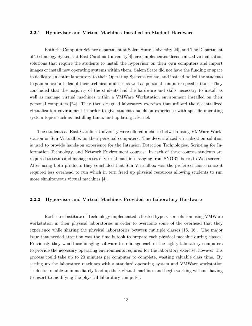
2.2.1 Hypervisor and Virtual Machines Installed on Student Hardware
Both the Computer Science department at Salem State University[24], and The Department
of Technology Systems at East Carolina University[4] have implemented decentralized virtualization
solutions that require the students to install the hypervisor on their own computers and import
images or install new operating systems within them. Salem State did not have the funding or space
to dedicate an entire laboratory to their Operating Systems course, and instead polled the students
to gain an overall idea of their technical abilities as well as personal computer specifications. They
concluded that the majority of the students had the hardware and skills necessary to install as
well as manage virtual machines within a VMWare Workstation environment installed on their
personal computers [24]. They then designed laboratory exercises that utilized the decentralized
virtualization environment in order to give students hands-on experience with specific operating
system topics such as installing Linux and updating a kernel.
The students at East Carolina University were offered a choice between using VMWare Work-
station or Sun Virtualbox on their personal computers. The decentralized virtualization solution
is used to provide hands-on experience for the Intrusion Detection Technologies, Scripting for In-
formation Technology, and Network Environment courses. In each of these courses students are
required to setup and manage a set of virtual machines ranging from SNORT boxes to Web servers.
After using both products they concluded that Sun Virtualbox was the preferred choice since it
required less overhead to run which in tern freed up physical resources allowing students to run
more simultaneous virtual machines [4].
2.2.2 Hypervisor and Virtual Machines Provided on Laboratory Hardware
Rochester Institute of Technology implemented a hosted hypervisor solution using VMWare
workstation in their physical laboratories in order to overcome some of the overhead that they
experience while sharing the physical laboratories between multiple classes [15, 16]. The major
issue that needed attention was the time it took to prepare each physical machine during classes.
Previously they would use imaging software to re-image each of the eighty laboratory computers
to provide the necessary operating environments required for the laboratory exercise, however this
process could take up to 20 minutes per computer to complete, wasting valuable class time. By
setting up the laboratory machines with a standard operating system and VMWare workstation
students are able to immediately load up their virtual machines and begin working without having
to resort to modifying the physical laboratory computer.
13

Chapter 3
The SUNYIT CS Virtualized Lab Environment
The goal of the SUNYIT CS Virtualized Lab Environment was to create a scalable virtu-
alization server array using Open Source technology for use by the SUNYIT Computer Science,
Telecommunications, and Network Computer Security programs. The servers are used by students
and faculty for hands-on laboratory exercises, as well as for research and development. A server
has also been dedicated to the Computer Science network administration department (Dognet) for
use in consolidating some of the older physical department servers, as well as the creation of new
production and development servers.
3.1 Project Requirements
Besides providing virtual machines to end users, there were other requirements that needed
to be met in order for the SUNYIT CS Virtualized Lab Environment to be considered a successful
implementation. Scalability was a major concern since the VLE needed to be able to cope with
increasing class enrollment, as well as the addition of new courses in the future. The VLE also had to
provide a secure way for students to access their virtual machines from the laboratories on campus,
as well as remotely from the dormitories or their homes. Virtual machine isolation was also an
absolute necessity, and a solution was required in order to keep student and experimental virtual
machines separated from the production network. The following sections describe the processes
involved in setting up the SUNYIT CS Virtualized Lab Environment, as well as illustrate how the
various requirements were satisfied.
3.2 Choice of Hypervisor
Due to budget constraints a free and Open Source hypervisor solution was deployed. There
are many virtualization products offered today, and all of the major players offer their hypervisor
14

for free. However not all of them are Open Source, and additional costs tend to creep up to unlock
functionality via separate utilities. Some of these products are; Microsoft Hyper-V[27], Citrix
XenServer[26], and VMWare ESXi[28]. Although they are all very powerful and capable products,
the extra costs involved to effectively utilize them was a limiting factor. So instead the decision
was made to use Xen[29], the Open Source hypervisor.
Citrix bases all of its product on the Open Source Xen hypervisor technology, and after some
research it was discovered that the Xen community developed an Open Source version of the Citrix
XenServer called Xen Cloud Platform[30] which is a clone of Citrix XenServer version 5.6 FP1. It
uses the same Xen API calls as Citrix XenServer, and can be managed effectively using the free
Citrix XenCenter[31] virtual server management utility.
Xen Cloud Platform (XCP) is a fairly new Linux distribution that runs the Xen hypervisor
and a minimal CentOS Linux based host operating system (a.k.a. Domain0). Because it is so new
and still considered to be in a testing state there is very little documentation available. Most of
the installation and setup performed was done by trial and error, however since XCP is based on
Citrix XenServer version 5.6 FP1, the manual[26] for that specific product was helpful in figuring
out the API commands necessary to setup the servers.
3.3 Server Hardware Specifications
The project began with the construction of three identical custom built, quiet computing,
rack mountable servers. The parts were ordered from the Internet, and the servers were built in
house. The following hardware was used in each server:
• Motherboard: SUPERMICRO MBD-X9SCM-O Server Motherboard (Sandy Bridge) w/ 2
integrated 1000MB Intel NIC’s
• Processor: Intel Xeon E3-1240 @ 3.30GHz Quad Core w/ Hyper Threading
• RAM: 16 GB Crucial DDR3 SDRAM ECC Unbuffered Server Memory
• Hard Drives: 2x Seagate Momentus XT 500GB Hybrid
• Hard Drive Mounts: 2x Mushkin Enhanced drive adapter bracket
• Rack Mount Case: Antec Take 4 + 4U With 650W Power Supply (Quiet Computing)
• Rack Rails: Antec 20” Side Rails
15

Total Cost Per Server : $1,331.46
3.4 Installation of Xen Cloud Platform
After the servers were assembled trial installations were performed and some issues were
encountered. Two of the initial three servers were locking up repeatedly during heavy I/O usage.
At first overheating was suspected but after extensive hardware stress testing and part swapping it
was deduced that two out of the three motherboards were found to be faulty and were ultimately
returned for repair. Once the faulty hardware was replaced and the systems were retested the
installation of Xen Cloud Platform was initiated on the three servers.
Hardware stress testing was performed by using the Memtest86[36] and Stress[37] utilities.
Memtest86 is available on most Linux distribution installation images, and can be run by simply
booting the CDROM and choosing Memtest86 from the list of boot options. The Memtest utility
is used to verify that the memory installed in the system is healthy. Stress is a utility available as
a package in most major Linux distributions. Once installed the utility can be used to generate
CPU, memory, I/O, and disk stress on a system. The utility is completely configurable by the user,
and can be utilized to generate artificially high workloads to test the components of a system to
verify their integrity. Stress can also be used to get an idea as to how much of a load the system
can handle. Stress was run on all three servers with a constant load average around 80 for one
week to verify the servers were capable of handling heavy loads for a long period of time. All three
servers showed no signs of hardware failure or overheating during the testing phases, and were
consequently pushed into the development phase.
The initial XCP installation was pretty straight forward. After answering a few prompts and
setting up the management interface IP address settings the servers were rebooted. Once the
server finished booting an ncurses based menu appeared on the screen which displayed some basic
information about the server, and allowed for a few simple configuration settings to be edited as
well as provided menu options to control installed virtual machines and other resources. Once the
networking for the management interface had been established this menu was also accessible via
SSH as shown in figure 3.1.
All three servers were equipped with two 500GB hard drives. The operating system installation
was performed using only the first hard drive (/dev/sda), and an LVM partition was created using
the entire space available on the drive. After the installation was completed a 50GB ext3 partition
was setup on the second hard drive (/dev/sdb) in each machine to be used as a local ISO image
16
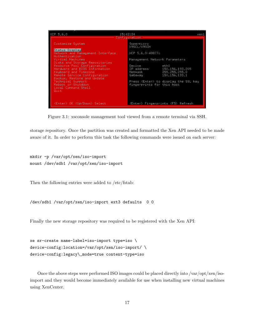
Figure 3.1: xsconsole management tool viewed from a remote terminal via SSH.
storage repository. Once the partition was created and formatted the Xen API needed to be made
aware of it. In order to perform this task the following commands were issued on each server:
mkdir -p /var/opt/xen/iso-import
mount /dev/sdb1 /var/opt/xen/iso-import
Then the following entries were added to /etc/fstab:
/dev/sdb1 /var/opt/xen/iso-import ext3 defaults 0 0
Finally the new storage repository was required to be registered with the Xen API:
xe sr-create name-label=iso-import type=iso \
device-config:location=/var/opt/xen/iso-import/ \
device-config:legacy\_mode=true content-type=iso
Once the above steps were performed ISO images could be placed directly into /var/opt/xen/iso-
import and they would become immediately available for use when installing new virtual machines
using XenCenter.
17

After creating the ISO storage repository on the first partition of the second hard disk (/dev/sdb1)
there was still 450GB of free space left to use. The default LVM volume group that was setup on
the first hard disk (/dev/sda) was extended to include the rest of the space available on the second
drive. This gave each server an additional 450GB of space to house additional virtual machines
rather than just using the 500GB from the first hard drive. Whenever a new virtual machine is
created the Xen API creates a new LVM partition within the default volume group of the size
requested by the user. The use of Linux Volume Management provides a scalable storage solution
that allows for the addition of extra hard disks down the road. To add the rest of the second hard
drive to the default LVM volume group another partition was created on the second hard disk using
fdisk and was set to type 8e, which is LinuxLVM. The following commands were then issued to
extend the default LVM volume group to /dev/sdb2.
First the physical volume was created:
pvcreate /dev/sdb1
Then name of the default LVM volume group was discovered:
pvdisplay
Which returned a few lines of information, specifically the VG Name:
VG Name VG\_XenStorage-be47438c-f310-dcf6-744e-651ba2bfaff9
The newly created physical volume was then added to the existing volume group:
vgextend /dev/VG\_XenStorage-be47438c-f310-dcf6-744e-651ba2bfaff9 /dev/sdb1
The vgs command was then used to verify that the additional 450GB was added to the default
volume group.
18

3.5 Subnetting & Virtual LANs
Before discussing the network configuration of the SUNYIT CS VLE a brief introduction
to subnetting and virtual LANs must be provided. The SUNYIT CS VLE makes heavy use of both
concepts to provide virtualization services to end users with isolated networking support.
3.5.1 Subnetting
Subnetting allows a network administrator to break up a single network into multiple smaller
sub-networks call subnets. A subnet can also be referred to as a broadcast domain due to the fact
that all nodes on a single subnet are able to receive each others broadcast traffic because of direct
layer 2 network connectivity at the MAC address level. In order to traverse subnets layer 3 switching
or routing must be utilized to allow a node to communicate with other nodes on different subnets.
Firewalls and gateways are also employed to ensure that the smaller networks are isolated from
each another in order prevent access from unauthorized nodes on other portions of the network.
In order for a node on one subnet to access resources on another subnet a firewall rule needs to be
created to explicitly allow communication. Generally the rule is required to be set on the receiving
subnet’s firewall, however if two-way communication is necessary rules will need to be applied at
both ends.
To partition a network off into multiple subnets a network administrator must manipulate
the subnet mask portion of the network address which allows the administrator to break up the
larger network into smaller portions with slightly different network numbers. For instance the
Computer Science network at SUNYIT has been allocated a fraction of the campus class B network
(150.156.0.0/16). The department uses the sub-networks 150.156.192.0/21 and 150.156.200.0/21
which are then each split up into 8 different subnets. Table 3.1 illustrates only the subnets that are
accessible by the SUNYIT CS VLE. By splitting up the network in this manner network congestion
is reduced and isolation between the different networks is achieved.
19

Subnet Name Network Address Broadcast Address Subnet Mask Number of Hosts
CS Network 150.156.192.0 150.156.192.255 255.255.255.0 254Admins 150.156.193.0 150.156.193.255 255.255.255.0 254Faculty 150.156.194.0 150.156.194.255 255.255.255.0 254
Unix Labs 150.156.195.0 150.156.195.255 255.255.255.0 254Windows Labs 150.156.196.0 150.156.196.255 255.255.255.0 254
Dorms 150.156.197.0 150.156.197.255 255.255.255.0 254Printers 150.156.198.0 150.156.198.255 255.255.255.0 254Wireless 150.156.199.0 150.156.199.255 255.255.255.0 254
Admin Devel 150.156.200.0 150.156.200.255 255.255.255.0 254Student 150.156.201.0 150.156.201.255 255.255.255.0 254
Lab 192.168.195.0 150.156.202.255 255.255.255.0 254
Table 3.1: SUNYIT Computer Science network subnets available to the VLE servers.
3.5.2 Virtual LANs
In order to provide virtual machines access to each of the subnets listed in table 3.1 it
was necessary for the SUNYIT CS VLE servers to be connected to a managed switch capable of
Virtual LAN (VLAN) port assignment. This allows an administrator to assign each port on the
switch to a single VLAN which in tern is mapped to one of the subnets listed in table 3.1. Once
a node is connected to the switch port it then becomes part of the broadcast domain that the
VLAN is associated with, effectively connecting the node to all of the other nodes on the subnet
even if the switch is located in a different location. A trunked port is a switch port that has been
allocated multiple VLANs, and nodes or devices that are plugged into a trunked port may be
assigned to any of the available subnets attached to that port. Typically trunked ports are used to
create a backbone between switches so that VLANs can be extended across multiple buildings or
site locations. Individual ports on the switches can then be assigned to a single subnet effectively
extending the broadcast domain beyond a single switch. In the case of the SUNYIT CS VLE
servers the trunked port is used to provide VLAN access to the virtual machines. Table 3.2 lists
the VLANs available to the virtual machines running on the SUNYIT CS VLE, as well as their
corresponding subnets.
There is one other VLAN that has been created that is entirely separate from the Computer
Science and Campus networks. The VLAN is called the NCS Darknet, and has been assigned its
own private class B network using the 172.42.0.0/16 address space. Each student that uses the NCS
darkent is provisioned a class C subnet from the 172.42.0.0/16 network. The class C network that
the student is allocated uses a 29 bit subnet mask which gives each student 4 usable host addresses
to statically assign to their virtual machines.
20

VLAN Name Subnet Name
Network192 CS NetworkNetwork193 AdminsNetwork194 FacultyNetwork195 Unix LabsNetwork196 Windows LabsNetwork197 DormsNetwork198 PrintersNetwork199 WirelessNetwork200 Admin DevelNetwork201 StudentNetwork795 Lab
Table 3.2: SUNYIT Computer Science VLAN tags and their associated subnets.
3.6 Networking Configuration
Once the servers were ready to be placed on the Computer Science network each network
interface was assigned an IP address, and corresponding firewall rules were created to ensure proper
communication and security was achieved. The first network interface was assigned at installation
to be used as the management port, and was put on the CS administrator subnet. Firewall rules
were setup that only allow access to the management interface by authorized administrators and
the web access appliance. The management interface is the only interface that allows the use of
API calls over it, and by locking access down to authorized users and appliances only it prevents
unauthorized users from making changes to the system. The second network card was connected
to a virtual LAN trunked port on the switch, and setup to be used by the virtual machines for
network traffic. Multiple VLANs were created and bound to it for the machines to be assigned to.
By using VLANs on the second interface virtual machines are able to be placed on different subnets
depending on their use and who they are assigned to (see figure 3.2). For instance, if a machine is
to be used as a production server it could be placed on one of the production networks. A faculty
member may need a virtual machine setup for research use that could be assigned to the faculty
subnet, so they have easy access to it along with some level of isolation. Student virtual machines
are completely isolated from the production network and are usually assigned to a VLAN that is
located behind a protected gateway that provides very restrictive Internet access. Some courses
may require students to have a set of virtual machines that run operating systems with known
vulnerabilities so that they may be exploited. In these cases the virtual machines are restricted
to the isolated NCS Darknet VLAN with no external access to ensure that the integrity of the
Computer Science department’s network can be maintained.
21

Figure 3.2: Abstraction of typical virtual LAN usage on a SUNYIT CS VLE server.
By integrating the VLAN capabilities into the SUNYIT CS VLE, virtual machines can be
moved around between different subnets as needed. For example a planned production server could
be developed in an isolated VLAN, moved to another VLAN for testing, then finally moved to the
production VLAN when it is ready to be deployed. Virtual machines may also be assigned more
than one virtual network interface, allowing them to access multiple VLANs. In order to configure
the VLANs for use by the virtual machines the following tasks were performed:
First a new network with a label was created:
xe network-create name-label=network201
This returned a unique ID:
d14427c2-4940-0db1-7d96-f55434af319e
Then the VLAN tag 201 was assigned to this network and bound to the physical interface eth1.
xe vlan-create network-uuid=85a9aba5-73ea-4008-0a28-395c96be30fd \
22

pif-uuid=e602777f-b4e9-e231-7858-81189c47c434 vlan=201
Once all of the VLANs were created and assigned to the physical interface eth1, the network
interface itself needed to be assigned to a VLAN with and assigned an IP address. Firewall rules
were also configured so that the interface could pass network traffic and respond to requests. To
configure the eth1 network interface the following command was performed:
xe pif-reconfigure-ip uuid=d14427c2-4940-0db1-7d96-f55434af319e \
mode=static IP=192.168.201.11 netmask=255.255.255.0 \
gateway=192.168.201.1 DNS=192.168.201.3
By using the above command eth1 was assigned to VLAN 201 and was given a static IP address
on the student subnet.
3.7 Centralized System Admnistration
There were now three identical servers with Xen Cloud Platform installed, storage setup,
and networking configured. One thing to note here is that one could not simply clone the first
machine after it was complete in order to produce the second and third servers. Every resource
registered in the Xen API is assigned a unique ID that would complicate things immensely if the
machines were just clones of an original. All three machines would be setup with the exact same
UUIDs for each resource it held. Therefore it was necessary for each machine to be individually
setup from scratch.
The entire SUNYIT CS VLE is centrally managed by the use of the Citrix XenCenter product
(figure 3.3) as well as an open source product called OpenXenManager[32] (figure 3.4). These
applications allow administrators to remotely manage multiple XenServer based servers, pools, and
virtual machines all from a central location from either Windows or Linux machines. Through these
applications administrators can create, export, import, connect to, and manage virtual machines.
They also allow administrators to manage server resources, take snapshots of virtual machines,
create templates from existing virtual machines, and fine tune virtual machine configurations and
CPU priority. The use of virtual machine templates allow us to quickly deploy single virtual ma-
chines for students in a matter of minutes. Once a course master template is created an entire class
worth of virtual machines (20 to 25 machines) can be deployed in under an hour. We can export
23

virtual machines and templates so that they can be backed up over the network or imported into
other Xen servers to be used to create new virtual machines. Students may also request an export
file of their virtual machines at the end of the semester so that they may import it into one of
the popular hosted hypervisor desktop virtualization products such as VMWare Workstation[33]
or Oracle VirtualBox[34] to continue experimenting on their own.
Figure 3.3: Citrix XenCenter running on Windows XP.
24
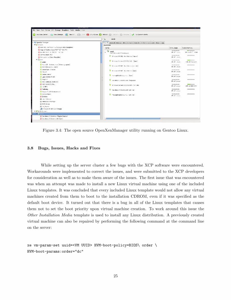
Figure 3.4: The open source OpenXenManager utility running on Gentoo Linux.
3.8 Bugs, Issues, Hacks and Fixes
While setting up the server cluster a few bugs with the XCP software were encountered.
Workarounds were implemented to correct the issues, and were submitted to the XCP developers
for consideration as well as to make them aware of the issues. The first issue that was encountered
was when an attempt was made to install a new Linux virtual machine using one of the included
Linux templates. It was concluded that every included Linux template would not allow any virtual
machines created from them to boot to the installation CDROM, even if it was specified as the
default boot device. It turned out that there is a bug in all of the Linux templates that causes
them not to set the boot priority upon virtual machine creation. To work around this issue the
Other Installation Media template is used to install any Linux distribution. A previously created
virtual machine can also be repaired by performing the following command at the command line
on the server:
xe vm-param-set uuid=<VM UUID> HVM-boot-policy=BIOS\ order \
HVM-boot-params:order="dc"
25

Where VM UUID is the UUID returned for the specific virtual machine when using the xe
vm-list command. This command sets the boot order for the virtual machine to ’dc’ (CDROM
then hard drive).
The second bug that was encountered took 30 days to show itself, and had to do with licensing.
XCP is supposed to be free and Open Source software with no license restrictions, however when
the developers were porting XenServer they neglected to remove the license file that corresponded
to it and since XenServer has a trial license of 30 days that also applied to XCP. To fix this issue the
Xen API service needs to be stopped, and a minor edit to the file /var/xapi/state.db is necessary.
In the file there is a field called expiry, setting the variable to 30 days in the future will fix the
license issue temporarily. This bug is supposed to be fixed in the next XCP update, but for the
time being a bash script was written that performs the task automatically.
The last bug encountered was similar to the second. Whenever an administrator tried to take
a snapshot of a virtual machine from XenCenter on a Windows machine they would get an error
that stated: Snapshots require XenServer 5.5 or later. This seemed a bit strange since XCP was
based on XenServer 5.6 FP1, and it turned out that the Xen API needed to be fooled again. The
Xen API service needed to be stopped, and a minor edit to the file /opt/xensource/bin/xapi was
required. Changing the version variable from 1.1.0 to 5.6.0, and restarting the service after the
change allowed snapshots to be taken from XenCenter on Windows again. This fix will not persist
after an update to XCP so a simple script was created that can be manually run to make the change
after an update.
3.9 User Access and Authentication
Once all of the servers were setup and the bugs were squashed it was necessary to implement
a way for administrators to be able to provision virtual machines to individual users, as well as
allow those users to access their virtual machines via a web page by authenticating with their CS
LDAP credentials. After trying a few different approaches an Open Source project called XVP
Appliance[35] was deployed which is designed to be a drop in virtual machine that could be used
to access virtual machines securely over the web that were hosted on Citrix XenServer and XCP
servers. To install the appliance the image was simply imported it into the Xen1 server, and booted
up. The hostname was changed to xen1-web, and it was assigned an IP address on the student
subnet. Firewall rules were created in order to allow traffic to access it as well as give it access to
the management ports on all of the Xen servers. Then the appliance was configured to use the CS
LDAP server for authentication. Once the initial configuration changes were made a command line
26

utility was used to add the three server pools to the appliance, which also added the corresponding
virtual machines that were assigned to each pool. Users were also added via the utility simply by
going to the user menu and typing in a CS LDAP user name to add to the system, then assigning
that user a virtual machine from a pool. Access rights are used on a per machine basis to allow for
fine grained control on who gets to do what with each virtual machine.
Once a user has been setup in the system they can visit https://xen1-web.cs.sunyit.edu in a
Java enabled browser to access their virtual machines. Upon visiting the site the user is prompted
for their authentication credentials, then is displayed with a list of virtual machines that they have
access to. Controls are provided that allow the user to start, shutdown, and restart each machine.
They also can gain console access to their machines through the interface. All virtual machine
console communication is done over the standard VNC port 5900 from the web server to the host
server the virtual machine resides on. The end user only needs access to ports 443 and 5900 on the
web server for secure HTTP communication. Figure 3.5 illustrates how an end user access their
virtual machines over the Internet through a standard Java enabled web browser.
Figure 3.5: Abstraction of how users access their virtual machines via a web browser.
27

3.10 Server Monitoring
Server monitoring, metrics, and alerting for the SUNYIT CS VLE as well as all other servers
and lab computers located on the Computer Science network are performed by a virtual machine
on Xen1 running Nagios[38]. Nagios is an enterprise level IT infrastructure monitoring service that
can be used to keep track of server resources such as CPU, memory, and disk utilization. It can also
be configured to monitor services running on a host, as well as send out alerts when those services
are no longer detected. An agent is setup on each host that requires monitoring, and corresponding
rules are put into place that perform actions such as collecting data and sending out email alerts
based on certain criteria. Graphs are also produced that provide historical views (4 hrs, 25 hrs,
weekly, monthly, and yearly) of the collected data. Table 3.3 depicts what is being monitored on
each VLE server, as well as the corresponding alert thresholds that have been set.
Service Warning Threshold Critical Threshold Alert Type
Disk Space / 3224 MB 3627 MB Email/TextDisk Space XenStore 200 GB 75 GB Email/Text
Server Load Average 1 15 30 Email/TextServer Load Average 5 10 25 Email/TextServer Load Average 15 5 20 Email/Text
NTP Time Offset 1 min 5 mins Email/TextSSH Service on eth0 N/A No Response Email/TextSSH Service on eth1 N/A No Response Email/TextRound Trip Times 3000 ms 5000 ms Email/Text
Table 3.3: Nagios monitoring of SUNYIT CS VLE servers.
By constantly monitoring the SUNYIT CS VLE servers administrators of the system are able
to determine if the servers are capable of handling the current semester load. The use of Nagois also
provides the administration team with immediate alerts of potential problems, failures, or other
events that require attention. Warning and critical alerting thresholds allow administrators fine
grained control over how and when they should be alerted. If a monitored service hits the warning
threshold an alert is dispatched before a potential problem actually occurs. The warning threshold
is typically set to a level that will still provide uninterrupted service, however that level tends to
be close enough to the critical threshold that the early warning alert may provide an administrator
enough time to resolve a potential issue before it becomes a real problem. If the critical threshold
is hit then another alert is dispatched warning the administrative team that immediate attention
is required.
28

3.10.1 Graph Data
Nagios provides a visual rendering of historical data in the form of graphs. This section
provides an overview of some of the historical data that is being collected from the SUNYIT CS
VLE servers, and its importance. In this section historical graphs from Xen2 will be explored,
mainly because it was the most utilized server during the Spring 2012 semester running 66 student
virtual machines for Network Computer Security classes.
The first measurement discussed is the time it takes a packet to reach Xen2 and return to
the Nagios server. This measurement is referred to as Round Trip Time (RTT), and is important
because not only does it tell an administrator that the server is online and responding, but it
also provides insight as to how well the server’s network interface and the network in general are
handling the virtual machine traffic load.
Figure 3.6 provides a one week view of the Round Trip Time measurement for Xen2. As seen
in the graph Xen2’s response time averaged at 1.21 ms with a high of 6.25 ms and a low of 0.87
ms. The graph shows very few spikes in response time, and illustrates that the server and network
are capable of handling the network traffic load imposed upon them by the virtual machines.
Figure 3.6: Round Trip Times over one week for Xen2.
Figure 3.7 illustrates the same data as Figure 3.6 over the course of one month. As depicted
by the graph the response times remain fairly consistent across the course of the entire month
averaging at 2.31 ms. A couple of spikes are seen on the graph, however the majority of the month
the response times are consistently low. This graph further proves that the server and network are
capable of handling the traffic load.
29

Figure 3.7: Round Trip Times over one month for Xen2.
Figure 3.8 graphs the disk space utilization for the root (/) partition on Xen2 over the course
of one month. Since this partition only contains the operating system files the contents of it are
rarely changed, and its size remains consistent. It is important to monitor this partition because
if it were ever to fill up the server would stop responding. Since this partition is rarely modified
large fluctuations in its size could be caused by log files becoming to large, which usually is a clue
that there is a bigger issue that requires investigation.
Figure 3.8: Disk space for / on Xen2 over one month.
The XenStore volume on Xen2 is the LVM volume group used to house all of the virtual disks
for each virtual machine running on the server. It is very important to monitor the remaining disk
space of the XenStore in order to make sure that there is always enough room for student virtual
machines. Figure 3.9 depicts the remaining disk space on Xen2 over the course of one month. By
looking at the graph a few interesting events can be interpreted. Disk space remaining on Xen2
stays fairly consistent throughout the month since each virtual machine is added to the server at
30

the beginning of the semester with a fixed allocation of disk space. Around week 15 (also see figure
3.8) two holes in the data are seen indicating that either Xen2 was down for those periods of time,
or the Nagios server or service was not running and no data was recorded for that time period.
The other event happens just before week 16 and illustrates that a virtual machine was deleted and
recreated a few times during the course of a day.
Figure 3.9: XenStore disk space on Xen2 over one month.
The final graphs to be discussed are those that depict historical load average data for the
SUNYIT CS VLE servers. Out of all of the historical data being graphed the load average graphs
provide the greatest insight as to how the servers are performing under the current semester virtual
machine load. Though the units are incorrect on each of the graphs due to a bug, the visual
data itself illustrates patterns of high and low virtual machine usage. Figures 3.11, 3.12, and 3.13
illustrate the load averages of Xen2 for 1, 5, and 15 minutes respectively over the course of one
month. As can be seen by the graphs the load average remains rather consistent with some periods
indicating higher than average loads. These spikes can be interpreted as periods of time when the
majority of the virtual machines on the server were running and in use. On average all machines
are not ran simultaneously over the course of a day, however there are times when students are
required to work on their virtual machines during a class or lab session which results in every virtual
machine being turned on and used at the same time. Those periods of time can be interpreted
as the large spikes in the graphs. The majority of the time only a fraction of the students are
working simultaneously on their virtual machines with the remaining being powered off to conserve
resources.
31

Figure 3.10: Load Average(1 min) for Xen2 over one month.
Figure 3.11: Load Average(5 min) for Xen2 over one month.
Figure 3.12: Load Average(15 min) for Xen2 over one month.
32

Through the use of monitoring and the graphing of historical data server performance over the
course of an entire semester can be visualized. This provides administrators with an extremely
useful tool that gives invaluable insight as to how each server is handling its respective virtual
machine load. By analyzing trends over an entire semester areas of improvement can be found,
and corrective measures can be taken to improve as well as scale the SUNYIT CS Virtualized Lab
Environment for future semesters.
33

Chapter 4
Implementations
The SUNYIT CS Virtualized Lab Environment was initially constructed to support classes
under the Network Computer Security curriculum, as well as to consolidate some of the older Com-
puter Science department servers. However, since the system was designed with scalability in mind
it has grown to be used for other purposes as well (see figure 4.1). This chapter explores the various
implementations of the SUNYIT CS Virtualized Lab Environment, as well as how the centralized
virtualized solution was used to overcome some of the complications that were experienced with
the previous physical laboratory environment settings.
Figure 4.1: The evolution and layout of the SUNYIT CS Virtualized Lab Environment (June 2011- May 2012).
34

4.1 Computer Science Department
One of the first implementations of the SUNYIT CS Virtualized Lab Environment was the
migration of some of the physical Computer Science servers to the new virtualization system. The
virtualization server named Xen1 was dedicated for department use, and student administrators in
the Dognet (Dogs) began working on migrating the physical servers to new virtual machines. After
noticing the advantages of using a virtualized environment many of the student administrators
also began creating sandbox virtual machines for themselves on Xen1 for development and testing
purposes.
By harnessing the power of one of the SUNYIT CS Virtualized Lab Environment’s servers the
department was able to remove a number older inefficient servers from the racks in the server room,
freeing up room for new equipment in the future. Besides freeing up space and offering a reduced
energy footprint, the migration also helped to reduce the noise level in the server room as well as
removed quite a bit of heat from some of the equipment racks. The servers that were migrated to
virtual machines also experienced a performance increase since the hardware in the virtualization
server is much newer than what previously used.
4.2 Network Computer Security Laboratories
After successfully migrating a number of the Computer Science department servers to the
new virtual environment, the student administrators began provisioning virtual machines on Xen2
and Xen3 which were allocated to host laboratory machines for Network Computer Security (NCS)
students. Each student was provisioned four virtual machines that they used simultaneously on an
isolated VLAN to perform network security and penetration testing laboratory exercises throughout
the semester. These exercises consist of using tools provided in a Backtrack virtual machine to
exploit vulnerabilities on Windows XP, Windows Server 2003, and Metasploitable Ubuntu target
virtual machines.
Before the introduction of the SUNYIT CS Virtualized Lab Environment students used end of
life hardware in a physical laboratory that was also used by Linux Systems Administration classes.
The classes generally consisted of twenty to twenty-five students that were broken up into groups
of four or five. Each group would be allocated four physical machines that they would perform the
laboratory exercises on. The four machines were able to communicate with each other by being
35

connected to an isolated ethernet switch with no external network access to prevent any of the activ-
ities from adversely affecting the production network or other students work (see figures 4.2 & 4.3).
Figure 4.2: Typical group setup under the original Network Computer Security physical laboratorysetting.
Though students were able to perform the laboratory exercises using the aged physical hardware,
many issues were experienced. The older hardware was sluggish and prone to failures that tended
to crop up at unforeseen and inappropriate times, causing frustration and delays for the affected
students. Overall management of the laboratory environment was cumbersome as well. Not only
did student administrators have to deal with the failing hardware, they also were in charge of
setting up the individual isolated group environments, as well as making sure that the appropriate
software was installed on each machine for the laboratory exercises. Since the computers were not
connected to the Internet or any network providing shared storage, student administrators were
required to install all software and updates manually at each station by using removable media
such as CDROM and USB storage devices.
36

Figure 4.3: Five groups of physical machines isolated from each other and the external world inthe original laboratory environment.
Another concern about the setup was that the students were forced to work in large groups due
to the lack of space and hardware available to the class. Typically one or two students would end
up doing most of the hands-on work while the other group members looked on. Though the group
as a whole would get credit for completing the laboratory exercises only a few students actually
received the hands-on experience that they were designed for.
Under the new centralized virtualization environment Network Computer Security students are
provisioned their own set of four virtual machines to work with. Since the virtual machines are
isolated from the Internet, students must use the web portal provided by xen1-web in order to gain
access to each of their machines. Once authenticated the students are then able to use the web
portal in order to control and work with all four of their virtual machines simultaneously from their
remote workstation (see figure 4.4).
37

Figure 4.4: Students access their virtual machines from a remote workstation via a web browserconnected to http://xen1-web.cs.sunyit.edu.
Due to the nature of the laboratory exercises performed in the Network Computer Security
classes virtual machine isolation was an important factor that needed to be addressed. Each of the
machines that the students were provisioned were intentionally left vulnerable to certain attacks so
that the students could gain hands-on experience finding and exploiting the those vulnerabilities.
If these machines were connected to an external network or the Internet others may be tempted
to try to exploit them and could cause major damages to the production network. To address
this an isolated VLAN called the NCS DarkNet was implemented and all student virtual machines
were assigned to it (see figure 4.5). The NCS DarkNet provides no access to any external networks
or the Internet. Each student is assigned a block of static IP addresses to use for their virtual
machines. By configuring all of their virtual machines’ network interface cards to use IP addresses
in their assigned subnet range they effectively allow them to communicate with each other so that
the laboratory exercises can be performed in isolation.
38

Figure 4.5: Student virtual machines are isolated to the NCS DarkNet VLAN where each studentis assigned a subnet to use for their virtual machines.
The transition to the new virtualized environment helped to significantly reduce the admin-
istrative overhead required to maintain the previous physical laboratory environment. Instead of
having to maintain twenty to thirty end of life computers as well as a number of questionable eth-
ernet switches, student administrators are now only required to maintain a base set of four master
virtual machine templates. Changes such as software installations and updates are performed on
the master templates as needed, and new virtual machines can be created from the corresponding
templates in a matter of seconds. If the administrator needs access to external network storage
or the Internet to install a software package or update, he or she can simply change the template
virtual machine over to a different VLAN then return it to the NCS DarkNet when completed
before using it to provision new student virtual machines.
The key advantage to migrating the Network Computer Security laboratory to the SUNYIT
CS Virtualized Lab Environment is that each student is provisioned their own set of four virtual
machines, and they are no longer required to work in a large group competing for hands-on time.
Since the students virtual machines are available to them remotely neither space nor time need to
be dedicated for scheduled laboratories. Students are able to do their assigned exercises on their
own time either in the open laboratories provided by the school, or remotely on their own computers
by using the provided web portal to access their virtual machines. Also by transitioning from the
physical laboratory environment to a centralized virtualization solution downtime due to hardware
39

issues and maintenance are drastically reduced, increasing availability of services, and maximizing
the students potential to learn.
4.3 Asterisk Voice Over IP (VoIP) Laboratories
Upon seeing the success of the SUNYIT CS VLE’s implementation in the NCS course
laboratories a fourth server was provisioned to migrate the TEL500 Voice Communications class to
the Virtualized Lab Environment. Previously, students were put into groups of four to six students
and were required to perform laboratory exercises on two Pentium 4 class Asterisk machines. One
group would work on the two machines, and when they were finished with that day’s laboratory
exercise the other group would take over. Under the new SUNYIT CS VLE system, TEL500
students are each provisioned their own Asterisk virtual machine that they use to work on exercises
during the semester. By assigning each student their own machine, every student receives an equal
chance to gain the hands-on experience provided by the laboratory exercises. Students also gain
more opportunities to experiment on their own without affecting others work in their isolated
virtual machine, providing an improved overall learning experience for everyone involved.
The TEL500 Voice Communications course offered at SUNYIT is a Masters level Telecom-
munications course that provides knowledge of the components, operations, and services of analog
and digital local loop circuit switched networks, digital and VoIP PBXs, and signaling systems.
Advances in wire-line and wireless voice telecommunications networks including VoIP, power-line
communications, passive optical networks, and broadband wireless are investigated (SUNYIT Cat-
alog). Students are required to perform a series of laboratory exercises utilizing the Asterisk open
source PBX system that will foster an understanding of the inner workings and connection require-
ments of a Private Branch Exchange (PBX) system.
Traditionally the TEL500 Voice Communications course was taught with both lecture and
laboratory based portions. In the laboratory environment, students would take turns working in
groups on two aging Pentium 4 computers running Asterisk, each containing a single port Foreign
Exchange Office (FXO) card connected to an analog phone line for Public Switched Telephone
Network (PSTN) access as shown in figure 4.6.
40

Figure 4.6: Original TEL500 Voice Communications laboratory setup.
Each group would work through the semester to edit the proper configuration files located in
/etc/asterisk. Once the first group was finished with a laboratory exercise they would clear the
configuration files and were responsible to reset the machines back to their original state so that the
next group could perform the same task. The laboratories would cover the topics of setting up the
two machines so that they could send and receive phone calls over the Session Initiation Protocol
(SIP), as well as create a communication link between the two servers using the Inter Asterisk
Exchange (IAX2) protocol to simulate a main branch to remote branch setup. Other laboratories
were also conducted to teach the students how to setup features such as voice mail, call waiting,
and how to utilize the FXO cards to provide access to the PSTN.
This setup worked well for a number of years with a small class of 8 to 10 students when Voice
over IP (VoIP) technology was just emerging on the scene. However in today’s society, VoIP is
everywhere, and this explosive growth [25] has also sparked a greater interest in telecommunications
students desire to learn and understand the technology. This rise in interest has shown itself in
41

TEL500 course enrollment, doubling the class sizes to around 20 students per semester. Conse-
quently the current two server setup has quickly become a bottleneck in the students capability to
experiment with and learn the technology.
Automating the configuration file cleanup was one proposed solution to deal with current short-
comings. The idea was to have login scripts that would automate a configuration file swapping pro-
cess each time a group logged into the machines. This would help to eliminate some of the issues
that were being caused by a previous group’s activities. Both of the machines would be initially
setup with Asterisk, and a default set of configuration files. When a group logs in a backup of
the configuration files would be saved to a safe location, and the groups configuration files would
then be loaded into /etc/asterisk. Upon logging out the groups configurations files would be stored
to their home directory in a /.asterisk-configs folder, and the default configuration files would be
copied back to /etc/asterisk. Though this solution would help to eliminate confusion when switch-
ing groups it still does not solve the bottleneck of 20 students having to work on a single set of
computers. It also does not eliminate the issue of one group possibly doing something to the oper-
ating system itself causing issues that affect all of the groups in general. The second solution that
was proposed was to use the SUNYIT CS Virtualized Lab Environment to create virtual machines
for the students to use. This solution eliminates all of the issues that were encountered by using
the two physical machines as well as help to remove the student bottleneck situation.
The migration of the TEL500 Voice Communications laboratory to a centralized virtualization
solution gives each student the chance to gain hands-on experience with the Asterisk open source
PBX software under an easily managed and scalable system. Each student is provisioned a vir-
tual machine loaded with the AsteriskNow Linux distribution created by Digium. The distribution
is a minimal CentOS installation with Asterisk 1.6 and FreePBX 2.7 installed. All of the virtual
machines are located on an isolated VLAN that is dedicated for student laboratory use only. All ex-
ternal access into the laboratory subnet from the outside is blocked by the use of a gateway/firewall
server. The laboratory virtual machines do have Internet access via the gateway, however due to
the restrictions on external access no ports may be forwarded to the virtual machines on the subnet
(see figure 4.7).
42

Figure 4.7: Basic overview of the virtual laboratory gateway setup.
Students can access the console on their machines either remotely by using the web portal
offered by the SUNYIT CS VLE or by using SSH on one of the physical laboratory computers that
are connected to the same subnet as the virtual machines. The FreePBX web interface on each of
the student’s virtual machines is only accessible from within the laboratory subnet. Students may
gain access by connecting personal laptops at approved locations, or use the physical laboratory
computers that are connected to the subnet. Savvy users may use an advanced form of SSH tun-
neling through a series of department servers and the laboratory gateway to access their FreePBX
web interface and SSH console from outside of the restricted laboratory subnet. However this is
a technically advanced procedure and instructions are provided as an optional laboratory exercise
for those who are interested.
It is important to note that though students may use various means to configure their virtual
servers remotely, they cannot connect remote SIP devices to their servers due to the restrictions
43
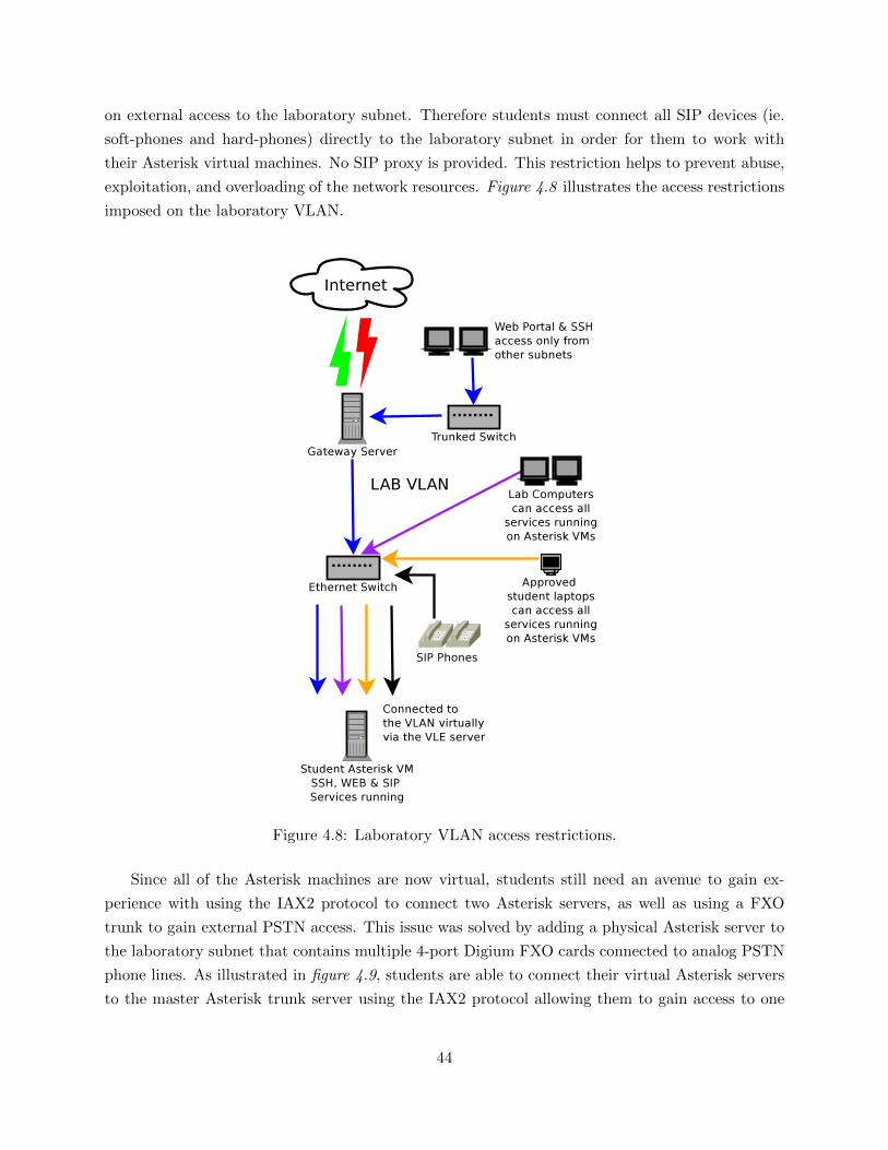
on external access to the laboratory subnet. Therefore students must connect all SIP devices (ie.
soft-phones and hard-phones) directly to the laboratory subnet in order for them to work with
their Asterisk virtual machines. No SIP proxy is provided. This restriction helps to prevent abuse,
exploitation, and overloading of the network resources. Figure 4.8 illustrates the access restrictions
imposed on the laboratory VLAN.
Figure 4.8: Laboratory VLAN access restrictions.
Since all of the Asterisk machines are now virtual, students still need an avenue to gain ex-
perience with using the IAX2 protocol to connect two Asterisk servers, as well as using a FXO
trunk to gain external PSTN access. This issue was solved by adding a physical Asterisk server to
the laboratory subnet that contains multiple 4-port Digium FXO cards connected to analog PSTN
phone lines. As illustrated in figure 4.9, students are able to connect their virtual Asterisk servers
to the master Asterisk trunk server using the IAX2 protocol allowing them to gain access to one
44

of the available FXO ports so that they may make and receive calls using the PSTN.
Figure 4.9: Student virtual machines connecting to a trunking server over the IAX2 protocol togain PSTN access via FXO cards.
Adhering to objectives in the traditional TEL500 laboratory setup, students are provided with a
series of laboratory exercises that are intended to teach them how to access their machines, initially
configure their server, as well as create and use SIP extensions with soft and hard phones. They
also learn how to deploy features such as call waiting, voice mail, auto-attendants, and hard-phone
provisioning. The main difference between the traditional setup and the SUNYIT CS VLE is that
each student now has his or her own Asterisk server to work with, and the ability to work at their
own pace without competition for hands-on time.
4.4 Linux Systems Administration Laboratories
The Linux Systems Administration class offered at SUNYIT is a Computer Science elective
that introduces students to Unix and Linux systems administration skills. Throughout the semester
students are required to research and implement a significant project of their choice that they work
on during the laboratory portion of the class. At the end of the semester they then must present
their work and findings to the entire class. Before the introduction of the SUNYIT CS Virtualized
45

Lab Environment students would use end of life hardware located in the same laboratory used
by the Network Computer Security classes for their projects. Most of the time the hardware was
sufficient for the individual projects, however on occasion a student would find that they required
more resources or flexibility than what the laboratory hardware had to offer, and therefore ended
up having to switch to a different project in order to compensate.
Upon the arrival of the SUNYIT CS Virtualized Lab Environment students in the Linux Systems
Administration class were offered the choice to either use the aged physical hardware that was
available in the laboratory, or virtual machines for their projects. While most chose to stick with
the physical hardware for the experience, a small percentage of the students opted to use virtual
machines. These mostly ended up being non-traditional part time students who commuted to
school and had full time employment. The virtual machine option allowed them more freedom to
work on their projects on their time rather than during the restricted laboratory hours. Since these
projects were individual projects that change from semester to semester, students that requested
virtual machines were just given a bare virtual machine shell with the installation image of their
requested operating system pre-loaded. The virtual machines were placed on the same laboratory
VLAN as the physical machines used by the other students in the class to ensure that they were
isolated from the production network. The students were then given access to the web portal to
install and work with their virtual machines.
4.5 Projects and Independent Studies
Though the intent of the SUNYIT CS Virtualized Lab Environment was to cater to the
needs of a few specific classes, we have also had some Computer Science and Telecommunications
students approach us requesting virtual machines to use for independent studies, Bachelor’s cap-
stone projects, and Master’s projects. These requests are generally easily met as the resource
requirements are usually small. The student’s virtual machines are place on a server with the least
load, and the student is given access to their virtual machine via the web portal. In these cases
students are provisioned a bare virtual machine shell with the ISO image of their required operating
system pre-loaded. When the student first boots up the virtual machine it automatically boots into
the installation media. The student is then required to install the operating system and configure
it per their individual needs. Since these are usually independent student project requests, no
templates are used. Typically the virtual machine will be placed on the laboratory VLAN where it
is isolated from the production network, but still has access to the Internet. If the student is doing
penetration testing or any other questionable activities the virtual machine will be placed on the
NCS DarkNet VLAN which provides no external access whatsoever. Under special circumstances
46

a student’s virtual machine may be placed on other subnets, however these cases are rare, and are
usually reserved for students who are doing work directly for the Computer Science department as
part of the network administration team.
47

Chapter 5
Discussion
Since its inception in 2011 the SUNYIT Virtualized Lab Environment has been heavily
utilized for multiple courses, and completely maintained by student administrators. The system
has proven to be an invaluable asset in its current implementations, and has demonstrated that it
can be scaled as needed to support increased class loads or new implementations. After a single
semester of deployment two more servers were allocated to the project in order to support other uses.
The two machines were retired Dell PowerEdge servers from the SUNYIT ITS department that
were re-allocated to the Computer Science department. Both servers had fairly similar hardware
consisting of two dual core Intel Xeon processors, 28GB - 32GB of RAM, and plenty of hard drive
space configured in RAID5. The machines were reconfigured and easily added to the system in a
matter of a couple of hours to support Telecommunications and Computer Science courses.
5.1 SUNYIT CS VLE Issues
The system is not without its flaws however. Due to the fact that the hypervisor used
was considered beta software there were still quite a few bugs that needed to be worked around
in order to provide a much smoother administrative experience (see section 3.8 for more details).
Also some students were affected by Java compatibility issues with the web portal which prevented
them from gaining console access to their virtual machines. The majority of the students that used
the SUNYIT CS VLE were using the official Java SDK and browser plugins on their computers.
However a few students were running Ubuntu based operating systems on their computers which
installs an open source version of Java called Icetea by default. The browser plugin that is installed
with the Icetea implementation of Java is not compatible with the SUNYIT CS VLE web portal,
and those students were instructed to switch over to the officially supported Oracle/Sun Java plugin
which corrected their problem.
One other problem was encountered near the beginning of the Spring 2012 semester that affected
a number of students in one of the Network Computer Security classes. Xen3 had developed memory
48

issues and could not be run reliably with all four RAM modules installed. The server was initially
deployed with 16 GB of ram (4 - 4 GB modules), however when all four modules were installed
the server would lock up whenever heavy I/O utilization occurred, such as exporting or importing
a virtual machine over the network. To temporarily fix the situation it was necessary to remove
the second channel of memory modules leaving the server with only 8 GB of memory. The server
initially contained close to 80 virtual machines that were carefully provisioned to ensure that there
was enough of the installed 16 GB of memory available for all of them to be running at the same
time. When two of the four memory modules were removed this effectively cut the amount of
installed machines that could be run simultaneously on the server in half, and consequently caused
the server to run out of memory when an entire class tried to boot their virtual machines at the
same time. The first 35-40 machines that were booted were allocated enough memory to run,
however as soon as the 8 GB of available memory was used up every machine thereafter failed to
boot. In order remedy the situation the remaining virtual machines were exported to Xen5 for the
remainder of the semester.
5.2 SUNYIT CS VLE Improvements
After using the system over the course of two semesters a few areas in need of improvement
were identified. One of the first improvements made was migrating the local ISO storage repositories
on each Xen server to a centralized NFS network share. By doing this the 50 GB that was set
aside on each machine for ISO image storage is returned to the LVM pool for use in creating
new virtual machines. This solution also simplifies administration by reducing the amount of ISO
image locations that need to be maintained. Secondly it was found that even though each server
had 1TB of hard drive space available, it was quickly running out due to the shear amount of
virtual machines that needed to be created during the semester. More drives could be added on
each server, however it was concluded that at some point the system will need to be migrated away
from local virtual machine storage to a centralized network attached storage solution. This would
simplify administration as well as improve reliability by allowing the servers to pool their resources
together in order to provide load balancing for running virtual machines.
5.3 Network Attached Storage Options
There are a variety of network storage options available in both the commercial and open
source markets. The commercial products offered by vendors such as HP and Dell are attractive,
however they prove to be expensive and detract from the original goal of the SUNYIT CS VLE
49
to provide a cost effective and open source solution. Open source products such as GlusterFS[39]
and Openfiler[40] offer highly scalable network attached storage solutions at no cost, and do not
require specialized hardware to run on. These solutions may be installed on retired or low end
servers to provide a cost effective and scalable storage solution. Openfiler very closely resembles
the HP NetAPP product and is designed to provide access to storage through a variety of protocols
such as iSCSI and fiber channel, as well as over Ethernet. It allows access to network shares via
CIFS, NFS or HTTP, and provides a web based interface for easy administration. GlusterFS is
not as user friendly as Openfiler due to the fact that it is command line driven, however it is easy
to implement and manage by experienced Unix/Linux administrators. GlusterFS utilizes a cluster
of computers in order to provide network attached storage over Ethernet using CIFS or NFS. It
is highly scalable and can be used to create raid volumes from the storage available in all of the
cluster nodes. GlusterFS is available as a package on most of the popular Linux distributions, and
could easily be used to turn a number of older unused computers into a robust network attached
storage solution for the SUNYIT CS VLE.
5.4 Metasploitable Ubuntu Virtual Machine Migration
The last item in need of discussing was the setup of the Metasploitable Ubuntu[41] virtual
machine template for the Network Computer Security laboratories. Metasploitable is a version
of Ubuntu that is setup to run services that contain known network layer vulnerabilities. It is
important that students have access to this virtual machine as it is used in a variety of their
laboratory exercises. The virtual machine is provided by the Metasploit Project and is available
for download via a Bittorent client. The virtual machine itself was created and is intended to be
used within VMWare’s Workstation product which is a hosted hypervisor solution. Many attempts
at exporting the virtual machine from the VMWare Workstation application into a format that
could be imported into the SUNYIT CS VLE ended with failure. Instead a different approach was
used to successfully create a Metasploitable virtual machine that could be run on the SUNYIT CS
VLE. The Metasploitable virtual machine installed within VMWare Workstation was booted with
a Clonezilla[42] CDROM image. Clonezilla allows a user to create an image of a hard drive that
can be used to clone the data to another hard drive. In this case it was used to create an disk
image file of the Metasploitable Ubuntu virtual machine running in VMWare Workstation. Once
the image was created a temporary virtual hard drive was created on one of the SUNYIT CS VLE
servers, and the image file was copied over to the new drive. Then a new virtual machine was
created with a new virtual hard drive and the Clonezilla CDROM image loaded as its initial boot
device. The temporary virtual hard drive was attached to the new virtual machine as a secondary
storage device, and the machine was booted into Clonezilla. Once booted Clonezilla was used to
50

clone the contents of the image file located on the temporary hard drive over to the primary hard
drive of the virtual machine. After the cloning process was completed the virtual machine was
shutdown, the Clonezilla CDROM was removed from the virtual CDROM tray, and the temporary
virtual hard drive was detached. The machine was then booted to its primary hard drive and the
Metasploitable Ubuntu distribution started successfully. After confirming that the virtual machine
worked as intended a template was created in order to be used to deploy student virtual machines
each semester.
51

Chapter 6
Conclusion
Overall response to the SUNYIT CS Virtualized Lab Environment was exceptional. Stu-
dents appreciated the fact that they could access their machines at their convenience, and from any
location rather than being restricted to a physical laboratory. The majority of the students used
their virtual machines both on and off campus, and all spoke highly of the performance. Of the
students surveyed that used the SUNYIT CS VLE over the course of the Fall 2011 pilot semester
100% of them replied that their potential to learn the subject content was maximized, and that they
would recommend the system for future class use. Administrators of the SUNYIT CS VLE found
it to be much easier to maintain and scale than the previous physical laboratory environments.
Instead of spending time addressing issues that previously plagued the physical laboratories each
semester, that time was redirected into researching and developing new and innovative solutions to
improve the department network, services, and end user experience as a whole.
Through the use of centralized virtualization technology, outdated and cumbersome laboratory
setups can be replaced with highly scalable approaches that can adapt to changing class sizes as
well as changing technologies. Templates can be used to create new virtual machines for students
on the fly and when the semester is over cleanup is as easy as removing the unused virtual machines
to free resources for next semester. If the operating system has been updated or changed, only
the master template needs to be addressed. Every machine created from it will be an exact copy
making deployment a simple task. The use of this approach in Network Computer Security and
Voice over IP laboratory settings allows an instructor to reduce bottlenecks created by shared
hardware as well as gain more space in the laboratory for devices like workstations, switches and
hard-phones that the students can use to interface with their virtual machines to gain invaluable
hands-on experience. Since we remove the physical machine aspect, students only require a space to
connect a computer to the restricted subnet to use a soft-phone or configure their virtual machines.
Funding that would have gone into purchasing more physical computers to use for the laboratories
could go into purchasing other equipment or software for the students to experiment with. For
example from personal experience, a school can purchase three to four mid-ranged enterprise class
SIP capable hard-phones for the price of a low end computer. Overall the virtualized solution
empowers students and allows them a greater opportunity to learn and succeed.
52

Bibliography
[1] P. Barham, B. Dragovic, K.Fraser, S. Hand, T. Harris, A. Ho, R. Neugebaurer, I. Pratt, A.Warfield. Xen and the Art of Virtualization. SOSP ’03, pages 164-177, 2003.
[2] R. McDougall, J. Anderson. Virtualization Performance Perspectives and Challenges Ahead.ACM SIGOPS Operating Systems Review, vol 44, issue 4, Dec 2010.
[3] Burdonov, A. Kosachev, P. Iakovenko. Virtualization-based separation of privilege: workingwith sensitive data in untrusted environment. VTDS 2009, March 2009.
[4] P. Li. Selecting and using virtualization solutions: our experiences with VMware and Virtual-box. Journal of Computing Sciences in Colleges, vol. 25, issue 3, pp. 11-17, Jan 2010.
[5] P. Li. Centralized and Decentralized Lab Approaches Based On Different Virtualization Models.Journal of Computing Sciences in Colleges, vol. 26, issue 2, December 2010.
[6] A Ketel. A Virtualized Environment for Teaching IT/CS Laboratories. ACMSE ’10, April 2010.
[7] J. Denk, L. Fox. The Evolution of Learning Spaces. SIGUCCS ’08, October 2008.
[8] K. Miller, M. Pegah. Virtualization, Virtually at the Desktop. SIGUCCS ’07, October 2007.
[9] O. Laadan, J. Nieh. Operating System Virtualization: Practice and Experience. SYSTOR 2010,May 2010.
[10] G. Collier, D. Plassman, M. Pegah. Virtualization’s Next Frontier: Security. SIGUCCS ’07,October 2007.
[11] D. Herrick, M. Ritschard. Greening Your Computing Technology, the Near and Far Perspec-tives. SIGUCCS ’09, October 2009.
[12] A. Gaspar, S. Langevin, W. Armitage, M. Rideout. March of the Virtual Machines: Past,Present, and Future Milestones in the Adoption of Virtualization in Computing Education.Journal of Computing Sciences in Colleges, vol. 23, issue 5, May 2008.
[13] C.Seay, G. Tucker. Virtual Computing Initiative at a Small Public University. Communicationsof the ACM, vol. 53, no. 3, pp. 75-83, March 2010.
[14] T. Bower. Experiences with Virtualization Technology in Education. Journal of ComputingSciences in Colleges, vol. 25, issue 5, pp. 311-318, May 2010.
[15] B. Stackpole. The Evolution of a Virtualized Laboratory Environment. SIGITE ’08, October2008.
53

[16] B. Stackpole, J. Koppe, T. Haskell, L. Guay, Y. Pan. Decentralized Virtualization in SystemsAdministration Education. SIGITE ’08, October 2008.
[17] B. Anderson, A. Joines, T. Daniels. Xen Worlds: Leveraging Virtualization in Distance Edu-cation. ItiCSE ’09, July 2009.
[18] N. Gephart, B. Kuperman. Design of a Virtual Computer Lab Environment for Hands-OnInformation Security Exercises. Journal of Computing Sciences in Colleges, vol. 26, issue 1,pp. 32-39, October 2010.
[19] Y. Wu. Benefits of Virtualization in Security Lab Design. ACM Inroads, vol. 1, no. 4, Dec2010.
[20] X. Wang. G. Hembroff. R. Yedica. Using Vmware Vcenter Lab Manager in UndergraduateEducation for System Administration and Network Security. SIGITE ’10, October 2010.
[21] X. Cao, Y. Wang, A. Caciula, Y. Wang. Developing a Multifunctional Network Laboratory forTeaching and Research. SIGITE ’09, October 2009.
[22] W. Armitage, A. Gaspar, M. Rideout. Remotly Accessible Sandboxed Environment with Appli-cation to a Laboratory Course in Networking. SIGITE ’07, October 2007.
[23] P. Albee, L. Campbell, M. Murray, C. Tongen, J. Wolfe. A Student-Managed NetworkingLaboratory. SIGITE ’07, October 2007.
[24] K. Grammer, J. Stolerman, B. Yi. Introduction of Virtualization in the Teaching of OperatingSystems for CS Undergraduate Program. Journal of Computing Sciences in Colleges, vol. 26,issue 6, pp. 44-50, June 2011.
[25] L. Madsen, J. Van Meggelen, R. Bryant. Asterisk: The Definitive Guide. O’Reilly Media, Inc.,CA, 2011.
[26] Citrix Systems. ”Citrix XenServer 5.6 Feature Pack 1 Administrator’s Guide”. Citrix SystemsInc., FL, 2011.
[27] Microsoft. ”Microsoft Hyper-v Server”. url: http://www.microsoft.com/en-us/server-cloud/hyper-v-server/.
[28] VMWare. ”VMWare ESXi”. url: http://www.vmware.com/products/vsphere-hypervisor/overview.html.
[29] Xen. ”Xen Hypervisor”. url: http://www.xen.org/.
[30] Xen. ”Xen Cloud Platform”. url: http://www.xen.org/products/cloudxen.html.
[31] Citrix Community. ”XenCenter”. url: http://community.citrix.com/display/xs/XenCenter.
[32] Open Xen Manager. ”Open Xen Manager”. url: http://sourceforge.net/projects/openxenmanager/.
[33] VMWare. ”VMWare Workstation”. url: http://www.vmware.com/products/workstation/.
[34] Oracle. ”Oracle Virtualbox”. url: https://www.virtualbox.org/.
54

[35] XVP. ”XVP Appliance - Cross-platform VNC-based and Web-based Management for CitrixXenServer and Xen Cloud Platform”. url: http://www.xvpsource.org.
[36] Memtest86. ”Memtest86 - A comprehensive, stand-alone memory diagnostic”. url:http://www.memtest86.com.
[37] Stress. ”Stress”. url: http://weather.ou.edu/ apw/projects/stress.
[38] Nagios. ”Nagios - The Industry Standard in IT Infrastructure Monitoring”. url:http://www.nagios.org.
[39] Gluster.org Community Website. ”GlusterFS is a cluster file-system capable of scaling to sev-eral peta-bytes”. url: http://www.gluster.org.
[40] Openfiler.com. ”Openfiler is an Open Source Network Attached Storage and Storage Area Net-work Solution”. url: http://www.openfiler.com.
[41] Metasploit Project. ”How to set up a penetration testing lab”. url:http://www.metasploit.com/help/test-lab.jsp.
[42] Clonezilla. ”Clonezilla - The Free and Open Source Software for Disk Imaging and Cloning”.url: http://clonezilla.org.
55

Appendices
56

Appendix A
NCS Virtual Lab Manual
57

NCS STUDENT GUIDE TO THE VIRTUAL LAB
From any of the open Windows or Linux computer labs open a web browser and go to:
http://xen1-web
If you are trying to access from off campus or in the dorms use the following URL:
https://xen1-web.cs.sunyit.edu
You will need a Java enabled browser!Note: Use Firefox for best performance & compatibility.
You should be greeted with a login prompt:
Login with your CS Username and Password. If you are having issues with logging in please contact one of the CS administrators in room C122.
Once you have successfully logged in you should see a list of virtual machines that have been allocated to your user account.
Notice that some of the machines are labeled as HALTED and others display as RUNNING with an uptime report.

To start a machine that is not running right click on the green power button next to its name and choose BOOT.
Notice once the machine powers up the green power button turns to a terminal icon. Right click the terminal icon and choose CONSOLE to gain console access to the machine.

After you click on the CONSOLE link you will be prompted by a java window that already has your login credentials entered. Just hit OK.
The console window will be displayed on your screen and you can now work inside your virtual machine. Notice the controls at the top of the console window.
Windows XP:

Backtrack 5:
When you are done working in your virtual machine make sure to shut it down to free up resources for other users. To do so either perform the normal OS shutdown procedures within the virtual machine, or close the console window and right click on the terminal icon next to the machines name and choose SHUTDOWN. You may also restart machines in the same way by selecting REBOOT from the menu or restarting within the OS itself.
If you encounter any issues with your virtual machines please contact one of the CS administrators in C122.

Appendix B
TEL500 Virtual Lab Manual
B.1 Getting Started
62

TELECOM STUDENT GUIDE TO THE VIRTUAL ASTERISK LABLab 01 – Accessing & Managing your Asterisk VM through the Web Portal
From any of the open Windows or Linux computer labs open a web browser and go to:
http://xen1-web
If you are off campus you can use the following address:
http://xen1-web.cs.sunyit.edu
Note: Use Firefox for best performance & compatibility.
You should be greeted with a login prompt:
Login with your CS Username and Password. If you are having issues with logging in please contact one of the CS administrators in room C122.
Once you have successfully logged in you should see a list of virtual machines that have been allocated to your user account.
Notice that some of the machines are labeled as HALTED and others display as RUNNING with an uptime report.

To start a machine that is not running right click on the green power button next to its name and choose BOOT.
Notice once the machine powers up the green power button turns to a terminal icon. Right click the terminal icon and choose CONSOLE to gain console access to the machine.

After you click on the CONSOLE link you will be prompted by a java window that already has your login credentials entered. Just hit OK.
The console window will be displayed on your screen and you can now work inside your virtual machine.
AsteriskNow (Booting):

AsteriskNow (Ready for login):
At this point you may log into your virtual machine with the root user and password. Also be sure to note the IP address that is displayed. That is the address of your server and is also the address that you will input into a web browser to access the FreePBX web frontend.
When you are done working in your virtual machine make sure to shut it down to free up resources for other users. To do so either perform the normal OS shutdown procedures within the virtual machine (type shutdown -h now at the command line), or close the console window and right click on the terminal icon next to the machines name and choose SHUTDOWN. You may also restart machines in the same way by selecting REBOOT from the menu or restarting within the OS itself (type reboot at the command line).
If you encounter any issues with your virtual machines please contact one of the CS administrators in C122 or by email at [email protected].

B.2 Accessing an Asterisk VM via SSH
67

TELECOM STUDENT GUIDE TO THE VIRTUAL ASTERISK LABLab 02 – Accessing your Asterisk VM via SSH
In the first lab you learned how to access and manage your Asterisk virtual machine through the web portal at http://xen1-web while on campus, and at http://xen1-web.cs.sunyit.edu if you are off campus. There may be times however when you need to access your server directly via SSH rather than using the browser to access the server's console. Due to the fact that the server's IP address is on a restricted subnet that can only be accessed in the telecom lab you will either need to be on a computer in the lab that is on that same subnet, or use some SSH tunneling magic to access your server from outside of the restricted subnet.
This lab will illustrate how you can access your server's command line by using SSH, as well as how to create an SSH tunnel to proxy your web traffic through so that you may access your server's FreePBX web frontend in the Firefox web browser.
Note: This tutorial assumes that you are using a Linux distribution to connect from. You may be able to apply the same concepts illustrated here with Putty and Firefox on a Windows based machine. See the end of this document for a link that may help.
Lets begin with the simplest of connection scenarios:
Life is simple if you are in the lab and on a computer connected to the correct subnet. Just open up a terminal and type:
ssh [email protected] (where XXX is the last octet of your server's IP address)
You will then be prompted for your server's root password, enter it and you will have root access to your AsteriskNow server.

While you are on that subnet you may also access your FreePBX web frontend by just pointing your browser to the server's IP address http://192.168.195.XXX. You should then see the following web page:
Don't do anything yet! You still need to perform updates before configuring anything. This lab is just to show you the different ways of accessing your server. The next lab will cover setup and system and FreePBX updates.
Second Scenario – From outside the restricted subnet (anywhere else including the Gentoo lab and Fang on campus!)
In order to access the SSH terminal and FreePBX web frontend from outside of the restricted subnet we need to configure SSH on our client. Open up a terminal with your normal user and type the following:
vim .ssh/config
or
nano -w .ssh/config
This should open an editor, and if you have not configured the file before it will be empty.
Add the following lines to the file:
Host gwForwardAgent yesHostName gw.cs.sunyit.eduUser INSERT_YOUR_CS_USERNAME_HERE
Host myvoipvmForwardAgent yesHostName 192.168.195.XXXUser rootProxyCommand ssh gw nc 192.168.195.XXX

Note: Remember to change the XXX to your IP address.Then save and close the file. What you just did is setup an SSH config file that will allow you to just type ssh myvoipvm at the command line on your computer and it will proxy the SSH connection through the CS firewall gw using netcat, and connect you to your server on the other side of the firewall.
So now as your normal user on the machine type:
ssh myvoipvm
Note: You will be prompted for two passwordsThe first password that you are prompted for is your CS account password for gw. Enter it and you will then be prompted for the second password. This is the root password for your Asterisk server. Once entered you will be at the root command prompt on your Asterisk server. You can streamline the whole process by using ssh keys if you wish. That will be left for you to explore on your own!
Gaining SSH access is pretty straight forward. Now that you have your SSH config file setup you can use the same connections to setup a proxy so you can access your FreePBX web frontend in Firefox. To do so open up a new terminal window under your normal user and type the following:
ssh -D 1080 myvoipovm
You will again be prompted for the two passwords. First your CS password for gw then your root password for your server. Once entered you will have a root terminal on your server. Leave the terminal window open to maintain the tunnel connection, then open Firefox.
In Firefox go to Edit → Preferences → Network Tab → Settings → Manual Proxy Configuration
Then make sure all of the settings are exactly like the image below:

Click OK and close the rest of the windows to return to the browser.
What you just did is created what is called a “SOCKS” proxy over your SSH connection to your server using port 1080. You then configured Firefox to use this tunnel for all of its web traffic. The tunnel starts at your computer (localhost), and goes through the SSH connection to the server using port 1080.
Once the tunnel is established, and Firefox is correctly configured you may type in your server's IP address in the address bar to access the FreePBX web interface. You should then see the following page displayed again:
When you are all done working in your FreePBX web frontend and wish to reset Firefox back to a normal non-proxied connection just go to Edit → Preferences → Network Tab → Settings and select: Use System Proxy Settings.
Link For Windows Users:
How to create a Firefox SOCKS proxy with a Putty SSH tunnel:http://www.devdaily.com/unix/edu/putty-ssh-tunnel-firefox-socks-proxy/1-putty-ssh-tunnel-introduction.shtml

B.3 Intial Configuration of Virtual Machine
72

TELECOM STUDENT GUIDE TO THE VIRTUAL ASTERISK LABLab 03 – Initial Configuration & Updating
The AsteriskNow virtual machine that you have been allocated this semester has a pre-installed copy of the AsteriskNow Linux distribution from Digium (http://www.digium.com/en/) . You can read more about this distribution here:
http://www.asterisk.org/asterisknow
Your virtual machine is a clean installation of the AsteriskNow distribution, no pre-configuration or updates have been performed. This lab exercise will take you through the process of initially configuring your server, updating the system and Asterisk software, and finally updating FreePBX to the latest version.
To start first access your virtual machine from the web portal at http://xen1-web as outlined in the first lab exercise. Once there start your machine if it is not already on and gain console access to it.
By default your server has been automatically allocated an IP address via DHCP in the 192.168.195.XXX subnet. When your server initially boots up you will see the IP address listed in the console window. You can also get this information by typing ifconfig eth0 at the command line:
At boot up:

using ifconfig eth0 as root:
Note: Once you have your server's IP address you may proceed with the rest of this lab using the web based console, or you can use SSH to access your server as outlined in the second lab.
Updating the CentOS Linux Distribution and Asterisk Software:
Log into your server as root with the password that was provided to you by your instructor. Then type:
yum update
You will see a list of System packages scroll by that need to be updated then it will prompt you if it is OK to download them. Type y and hit enter. The packages will be downloaded, then you will be prompted again to install them. Type y again and hit enter. After all of the packages are updated you will be returned to the root command prompt. Type yum update once again to update the Asterisk packages, hitting y whenever necessary. After you have finished updating the System and Asterisk packages reboot your server by typing reboot.
The distribution is now updated as well as the Asterisk software. The next thing to update is the FreePBX web frontend. To do this you need to open up a web browser, and point it to the IP address of your server.
Note: Refer to the second lab exercise if you are doing this from outside of the restricted lab subnet.

You should see the following web page:
Click on FreePBX Administration, and log in as user: admin with the password provided by your instructor which will take you to the Server Status Page:

Now it is time to update FreePBX from 2.7 to 2.9. There are a few steps to this and they must be performed in the correct order.
To upgrade FreePBX select Module Admin from the Setup menu. In the drop down box select extended repository, click OK on the prompt, then click on Check for updates online.
Module Admin:
After Checking for updates:

You will now see a list of packages, some of them will be marked with an available update, and some will be marked as not installed. The only package we are concerned with at the moment is the 2.8 Upgrade Tool. Click on it and then select Download and Install. Then click on Process.
Confirm the installation, click return when the orange box pops up, then click the orange Apply Configuration Changes button at the top. Another orange box will pop up, click Continue with reload.
Note: Pay special attention to the Apply Configuration Changes button as it will appear any time you make a change in FreePBX. The button will need to be pressed in order for the changes to be applied. It is very easy to miss!
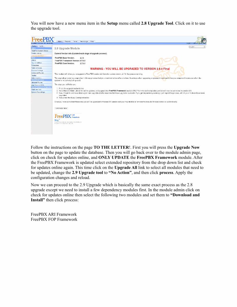
You will now have a new menu item in the Setup menu called 2.8 Upgrade Tool. Click on it to use the upgrade tool.
Follow the instructions on the page TO THE LETTER!. First you will press the Upgrade Now button on the page to update the database. Then you will go back over to the module admin page, click on check for updates online, and ONLY UPDATE the FreePBX Framework module. After the FreePBX Framework is updated select extended repository from the drop down list and check for updates online again. This time click on the Upgrade All link to select all modules that need to be updated, change the 2.9 Upgrade tool to “No Action”, and then click process. Apply the configuration changes and reload.
Now we can proceed to the 2.9 Upgrade which is basically the same exact process as the 2.8 upgrade except we need to install a few dependency modules first. In the module admin click on check for updates online then select the following two modules and set them to “Download and Install” then click process:
FreePBX ARI FrameworkFreePBX FOP Framework

2.9 Dependencies:
After they are installed apply the configuration changes and reload Asterisk. Then in module admin click check for updates online again, select the 2.9 Upgrade Tool and choose “Download and Install”, then click on process to install it. When it is finished installing apply the configuration changes and reload. Then select 2.9 Upgrade Tool from the Setup menu.

Once again follow the instructions on the page TO THE LETTER!. First you will press the Upgrade Now button on the page to update the database. Then you will go back over to the module admin page, click on check for updates online, and ONLY UPDATE the FreePBX Framework module. After the FreePBX Framework is updated select the basic and extended repositories, and check for updates online again. This time click on the Upgrade All link to select all modules that need to be updated, and then click process. Apply the configuration changes and reload. Now make sure the basic and extended repositories are selected and check for updates online again. Choose Upgrade All and then click process. Once it is finished updating the modules apply the changes and reload.
Congratulations! Your have just fully updated your Asterisk server and its web management utility.
Now as an exercise use the FreePBX management interface to create a new user that can administer all sections of the FreePBX web interface. (hint: try Administrators menu link, and look at the current admin user's settings)
After you have created the new user, try to login as that user. You should have all of the same access rights as the admin user. As the current user try to create a few new users with more restricted access rights. Log in as those users and report any changes you notice.
When finished log back in as the admin user and delete all of the new user accounts that you created, leaving just the admin account. (hint: click on the user name in Administrators)

B.4 Configuring IPTables Firewall
81

TELECOM STUDENT GUIDE TO THE VIRTUAL ASTERISK LABLab 04 – Server Hardening With IPTables
This lab will take you through the process of setting up and configuring IPTables on your AsteriskNow virtual machine. The purpose of using IPTables on your server is to restrict network access to your server by only opening the necessary ports needed for the server to do its job. The rest of the ports remain closed and inaccessible from the network.
To start the lab access the root command line on your server by either using the web portal at http://xen1-web or via SSH.
IPTables should already be setup and running on the server, however no rules have been applied. You can verify this by typing the following as the root user:
chkconfig iptables --list
The output should look similar to this:
Now verify that there are no rules present by typing the following:
iptables -L -v
This should output the following indicating that no rules are present, and that the default policy is to accept all incoming and outgoing traffic:

Now it’s time to add some rules!
The first rule will allow the firewall to accept any incoming packets as long as they are related to a previous packet. Essentially this allows you to get return packets from requests that you made on the network from the local machine. A good example is browsing the web. Without adding this rule you be able to send the request to the web server, but you would not get anything back because it would be blocked. Enter the following rule at the command line on your server:
iptables -A INPUT -m state --state RELATED,ESTABLISHED -j ACCEPT
The next rule to add will be the one that denies all incoming traffic:
iptables -P INPUT DROP
Then we need to allow communication to the loop-back device:
iptables -I INPUT -i lo -j ACCEPT
Now your rule list output should look like the following:
The IPTables firewall is now configured to allow outbound traffic and deny all incoming traffic accept anything that is related to a request made from the server. The next step is to start opening the necessary ports for the Asterisk server to work correctly with SIP, SSH, WEB, NTP, and TFTP clients. The following is a list of the ports that will need to be opened:
Port 123 UDP for NTP (Time)Port 69 UDP for TFTP (Phone provisioning)Port 5060 UDP for SIP (Phone Calls)Port 10000-20000 UDP for RTP (Phone Calls)Port 22 TCP for SSH (SSH Connection)Port 80 & 443 TCP for HTTP/HTTPS (Web)
As you may notice there is a mixture of UDP and TCP ports, as well as a range of ports for the RTP traffic that need to be opened.

EXAMPLES:
To open a single port the following syntax is used:
iptables -A INPUT -p PROTOCOL -m state --state NEW -m PROTOCOL --dport PORT_NUMBER -j ACCEPT
Here is an example that illustrates how to open TCP port 22 for SSH access:
iptables -A INPUT -p tcp -m state --state NEW -m tcp --dport 22 -j ACCEPT
To open a range of ports the following syntax is used:
iptables -A INPUT -p PROTOCOL -m state --state NEW -m PROTOCOL --dport PORT:RANGE -j ACCEPT
Here is an example that illustrates how to open UDP ports 10000-20000 for RTP traffic:
iptables -A INPUT -p udp -m state --state NEW -m udp --dport 10000:20000 -j ACCEPT
You may also enable logging on your rule set by adding the following rule last:
iptables -A INPUT -j LOG
This will force a log entry to be made in /var/log/messages every time a rule is tripped.
You can also delete a rule by using the following commands:
First get a numbered rule list:
iptables -L INPUT -n --line-numbers
Then delete the rule you want by using the line number:
iptables -D INPUT the_number
If you want to flush (delete) all of the rules from iptables, and reset it to the default accept all policy do the following:
iptables -F
NOTE: Once you do this you will have to re-enter all of your rules again, or import them from a backup file. Use this only if you really messed up and want to start over from scratch.

YOUR TASK:
Armed with the list of necessary ports as well as a few examples your task is to setup all of the required firewall rules necessary for your server to operate correctly. Once you have successfully completed this step save your iptables rules by issuing the following command:
/etc/init.d/iptables save
then:
iptables-save > /etc/iptables.bak
Your finished iptables rule list should look like the following when your done:
Your /etc/iptables.bak file should like like this when done:
To restore a set of rules from a backup file use the following syntax:
iptables-restore < /etc/iptables.bak
B.5 Configuring SIP Extensions
86

TELECOM STUDENT GUIDE TO THE VIRTUAL ASTERISK LABLab 05 – Setting up SIP Extensions and Soft-phones
This lab will guide you through the process of setting up SIP extensions on your AsteriskNow virtual machine that will be used to connect phones to the system. To begin make sure your virtual machine is powered up and note the IP address that is displayed on the console. Next access the FreePBX web front end for your virtual machine by using the server's IP address and login as the admin user.
Once logged in you will see a menu item called Extensions under the Setup menu. Click it and you will be taken to the “Add an Extension” page, where you can create new extensions that will be used by SIP devices on your Asterisk PBX phone system.
Since we will be dealing with the SIP protocol choose “Generic SIP Device” for the Device and click submit. This will take you to a very long page with many settings that are broken up into sections. Don't be too scared of all the options, you will only need to change a few of them at this time. We will only cover the sections that need changing, leave everything else set to default. First lets take a look at the Add Extension section:
In this section you only need to fill out the User Extension and Display Name fields. The User Extension can be any number you wish to use. Usually these are 3 or 4 digit numbers that begin in a certain range. (ie. 201, 202, 203...).

Next scroll down the page a bit and take a look at the Device Options section:
In the secret field type in the password the extension must use to authenticate. This can be a combination of letters and numbers. Leave dtmfmode to the default setting, and only change the NAT setting to yes if you are going to use the extension to access the Asterisk server from an external network behind a NAT enabled router or firewall.
The last section we are concerned about is the Voicemail & Directory section. This section allows you to create a voicemail account for the user extension on the server.
To enable the user extension's voicemail account change the Status option to Enabled then assign the voicemail account a password in the Voicemail Password field. You want to use a numeric password since the user will be required to key in the password from the phone dial pad. (ie. 1234)
If you want the server to send the user an email alert when they have a new voicemail message, enter the users email address in the Email Address field. You can also have the server send the voicemail message in the form of an attachment by changing the Email Attachment menu option to yes.
Once you are done click the submit button at the bottom of the page to add the extension. Now as an exercise create 4 more SIP extensions on your server.

Now that you have a few SIP extensions setup on your server you will need some phones to use them! There are many software based phones (soft-phones) that can be used with an Asterisk system. Some good ones are:
Xlite (Windows):http://www.counterpath.com/xlite-comparison.html
The free version of X-lite allows you to make basic phone calls, and is a perfect soft-phone for windows users wishing to experiment with soft-phones and Asterisk.
Ekiga (Linux):http://ekiga.org/
If you use Linux Ekiga is a great full featured open source soft-phone that is usually included in most distros by default. It is very easy to setup and works well with Asterisk systems.
A simple Google search will yield many more results. There are even SIP soft-phone apps available for Android and iOS devices.
Your task:
Required supplies: – 2 computers connected to the same subnet as your AsteriskNow machine in the Lab– 2 pairs of voip headsets, or microphones and speakers connected to the computers.
Download and install a soft-phone of your choice and configure it to use one of the extensions you created on your AsteriskNow server. You will need to read the documentation for your particular soft-phone in order to connect it to your server. Usually you will only need to configure the server address, SIP user account and password to register the device.
After you have successfully connected your soft-phone to your system dial *98 or *97 to access your voice mail. This is a good test to verify that it is working, and that your phone is able to dial. Note the difference between the two feature codes after you have tried them both.
What does each one do?
*98 -
*97 -

Next setup another SIP soft-phone on another computer, and connect it to one of the other extensions you created. Once it is registered to the server try to dial between the two extensions and verify that you can pass sound to and from both ends of the call. From one of the extensions put the other extension on hold. Did you hear music? Try the same thing from the other extension. After you have tested both extensions access the command line of your AsteriskNow virtual machine by using the https://xen1-web portal or by SSH. Leave the soft-phones connected and type the following as the root user:
asterisk -r
This will bring up the Asterisk Command Line Interface.
Type the following:
sip show peers
What was the output? Would you consider this a very useful command, Why?
When you are done type quit, and close out your connection to the server. Congratulations you now have a working phone system with useable SIP extensions!

B.6 Configuring an IAX2 Trunk Connection
91

TELECOM STUDENT GUIDE TO THE VIRTUAL ASTERISK LABLab 06 – Using IAX2 to Connect Two Asterisk Servers Together
In this lab you will create a connection between your Asterisk virtual machine and a physical Asterisk server that has been setup with multiple FXO ports so that you may gain outside access to the PSTN. This lab demonstrates the use of an IAX2 (Inter-Asterisk Exchange) trunk to connect the two servers together. In a the real world this could be used to connect the phone systems of multiple remote branches of a company to the main branch. Once the IAX2 trunk is established users may dial extensions on both ends, and all outbound calls to the PSTN can be forced to go through the main office.
In order to connect to the PSTN access server you must setup a new IAX2 trunk connection to it. There also needs to be a IAX2 trunk connection setup that points back to your server on the PSTN access server. Note: This should already be setup for you prior to this lab exercise.
In order to setup the IAX2 connection, login to your FreePBX web front end and do the following:
First select Trunks from the Setup menu, then choose Add IAX2 Trunk:

Next under General Settings set the Trunk Name field to: Master-IAXpeer
Then setup the fields under Outgoing Settings & Incoming Settings like so:

The following is a breakdown of the main settings in the image above.
Outgoing Settings
Trunk Name: Master-IAXpeer ;Name of the trunk connection
PEER Details:Host=192.168.195.161 ;IP Address of IAX2 Peer – ie. PSTN access serverusername=LastF-IAXuser ;Authentication username for IAX2 account on PSTN access serversecret=t3lc0m ;Authentication password for IAX2 account on PSTN access servertype=peerqualify=yestrunk=yes ;it is an IAX2 trunk connectionrequirecalltoken=no
Incoming Settings
USER Context: Master-IAXpeer ;Context for incoming connections from server
User Details:secret=t3lcom ;Authentication password for PSTN access server to use to connecttype=usercontext=from-internal
Once you have completed setting up the IAX2 trunk click Submit Changes. To verify that the

IAX2 trunk connection has been established SSH into your virtual machine and type asterisk -rvv to gain access to the Asterisk CLI. Once in the CLI type iax2 show peers and you should see something similar to the following output indicating that the trunk is online:

Next you will need to setup an outbound route so that your user extensions can call through the IAX2 trunk to the PSTN access server in order to use its outbound lines. To do this click on Outbound Routes in the Setup menu. Then use the menu to create a new route called Master-Ext