Embed Size (px)
Citation preview

Ron Johnson
Beam Position Monitors [email protected]
October 29-31, 20071
Beam Position MonitorsFAC Review
October 29-31, 2007
• Stripline BPM Performance
and AFE Modifications
• Cavity BPM Electronics
• BPM Digitizer Comparison
Ron Johnson
Beam Position Monitors [email protected]
October 29-31, 20072
Stripline BPM Performanceand
AFE Modification

Ron Johnson
Beam Position Monitors [email protected]
October 29-31, 20073
BPM Performance
Take data synchronized pulse-by-pulse
Use linear prediction of each BPM from adjacent BPMS
Example: Compare bunch
charge pulse-pulse
300 pulses 17 BPMs
Average rms/mean 0.0007
May include pulse-pulse variation in losses
Ron Johnson
Beam Position Monitors [email protected]
October 29-31, 20074
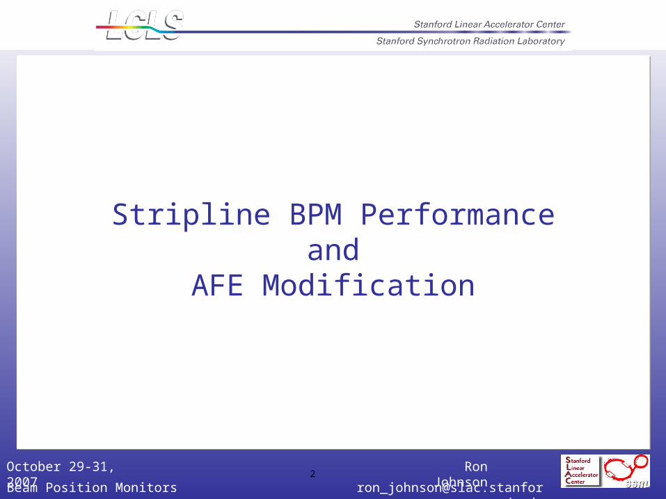
Performance
Predict BPM position reading from linear fit to adjacent BPMs (model-independent)300 machine pulses
Effective beam charge 0.35 nC x = 2.5 micronsy = 1.7 microns

Ron Johnson
Beam Position Monitors [email protected]
October 29-31, 20075
BPM Performance
Q~ 200 pC
Resolution requirement is 10 microns for the small aperture BPMs
Meets resolution requirements
Micro: Unit
Xmean (um)
Xrms (um)
Ymean (um)
Yrms (um)
X beam jitter
Y beam jitter
BPM Type
Comment
1 IN20:221 -14 10.6 -74 6.8 12 25 LA2 IN20:235 421 7.6 -884 7.5 43 39 LA3 IN20:371 118 7.2 114 3.2 90 43 SA4 IN20:425 -94 2.8 715 3.6 10 56 SA5 IN20:511 -354 6.3 475 2.9 88 15 SA6 N20:525 -401 3.9 579 2.9 61 17 SA7 IN20:581 -300 3.1 434 2.5 5 13 SA8 IN20:631 -106 4.2 343 9.6 42 31 SA bad Y connection9 IN20:651 -229 4.3 766 4.4 12 66 SA10 IN20:731 1955 58.7 375 4.4 238 33 SA dispersion11 IN20:771 -219 4.7 460 2.9 49 55 SA12 N20:781 -1061 8.6 84 3.3 93 42 SA13 LI21:131 -474 4.3 193 5.1 36 102 SA14 LI21:161 -821 3.9 116 3.1 34 30 SA15 LI21:201 -500 4 -606 3.8 27 33 SA16 LI21:233 8277 67.5 -329 14 516 56 SLA dispersion17 LI21:278 672 7.3 -23 3.5 102 14 SA18 LI21:301 -408 10.6 249 9.9 102 70 SA

Ron Johnson
Beam Position Monitors [email protected]
October 29-31, 20076
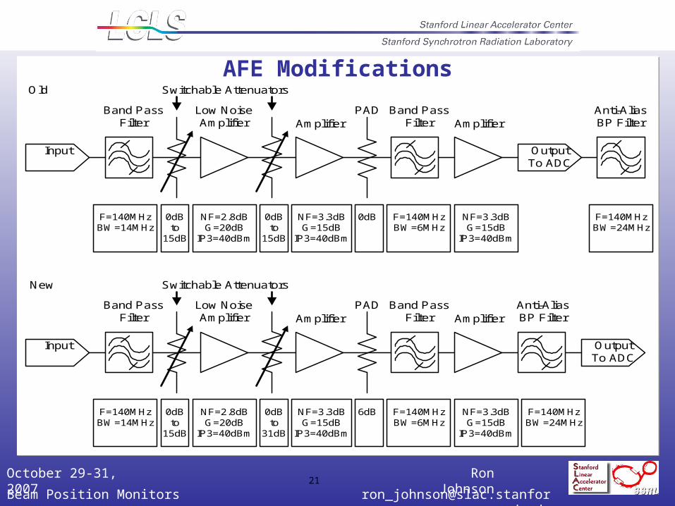
AFE Modifications
CAL – Additional switch to improve isolation
CAL – Add on/off control to oscillator
CAL – Replace BP filter with packaged unit
Chan – Replace 2nd attenuator with 0-31 dB unit
Chan – Put anti-alias BP filter on the PCB
Revise limiter
Revise layout and connectors

Ron Johnson
Beam Position Monitors [email protected]
October 29-31, 20077
Status
Plan to build 53 modules for BSY/LTU/Dump.Includes 3 spares for the injector.
And 3 modules for sector 24/25 (at the request of the commissioning team). Installation in January.
Most parts for AFE, PAD, and Clock Board on order (certainly long lead items).
Bulk of modules ready for installation in March/April.

Ron Johnson
Beam Position Monitors [email protected]
October 29-31, 20079
LTU and Undulator BPM System Specification
Parameter Specification Limit
Condition
Resolution < 1m 0.2 – 1.0 nC
+/- 1 mm range
Offset Stability < +/- 1m 1 hour
+/- 1 mm range
20.0 +/- 0.56 Celsius
Offset Stability < +/- 3m 24 hours +/- 1 mm range
20.0 +/- 0.56 Celsius
Gain Error < +/- 10 % +/- 1 mm range
20.0 +/- 0.56 Celsius
Dynamic Range, Position +/- 1 mm 10 mm diameter vacuum chamber
Dynamic Range, Intensity > 14 dB PC Gun
0.2 – 1.0 nC

Ron Johnson
Beam Position Monitors [email protected]
October 29-31, 200710
Cavity BPM Electronics
CavityBPM
X-BandReceiver
VMEADC
IOC EVR
LCLS Network
ADC Trigger
15-V Power SupplyControl/PowerDistribution
119 MHzClock and LODistribution
119 MHz ClockConditioner
LO
Control/Power
Horizontal
Vertical
Reference
ADC Clock
Control
UND Hall Support Building
Coupler

Ron Johnson
Beam Position Monitors [email protected]
October 29-31, 200712
BPM Digitizer ComparisonSteve Smith
August 8, 2007
Ron Johnson
Beam Position Monitors [email protected]
October 29-31, 200713
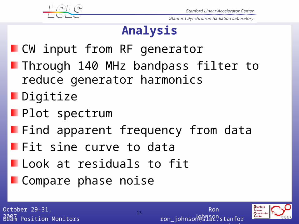
Analysis
CW input from RF generator
Through 140 MHz bandpass filter to reduce generator harmonics
Digitize
Plot spectrum
Find apparent frequency from data
Fit sine curve to data
Look at residuals to fit
Compare phase noise

Ron Johnson
Beam Position Monitors [email protected]
October 29-31, 200714
VME Digitizer @ -1 dBFS
Fit good to 6.5 ADC counts rmsENOB = 11.5Harmonics <-80dBc

Ron Johnson
Beam Position Monitors [email protected]
October 29-31, 200715
VME digitizer
PAD @ -1 dBFS
Fit good to 16 ADC counts rmsENOB = 10.2Harmonics <-72dBc

Ron Johnson
Beam Position Monitors [email protected]
October 29-31, 200716
Compare
Noise floor
Harmonic distortion
Other lines in spectrum
Input range

Ron Johnson
Beam Position Monitors [email protected]
October 29-31, 200717
Digitizer Comparison
VME 5 dB better on noise floor
VME 8 dB better on worst harmonic
Parameter VME PAD Comments
Amplitude -1 -12 -1 -12 dBFullSscale
Rms fit error 6.5 4.2 16 7.1 ADC counts
ENOB 11.5 12.1 10.2 11.3 Bits (ref Full Scale)
Worst harmonic
-80 -85 -72 -68 dBc
Phase noise (full spectrum)
0.013 0.031 0.53 1.9 degrees (includes harmonics)
(PAD dominated by 2nd harmonic)
Phase noise (<20 MHz)
0.008 0.014 0.014 0.021 degrees

Ron Johnson
Beam Position Monitors [email protected]
October 29-31, 200718
Comparison
SimplificationReduces the number of accelerator ethernet ports, private ethernet ports, and DIGI ports. Communication with the ADC is over the VME backplane.PAD would require enclosure and PS not yet designed.Simplifies clock distribution (10 vs 18 dBm input)
PerformanceReduces broadband noise and harmonics.FPGA has more computing power than the Coldfire.Comparable data transfer rates ( measured 28 Mbytes/s for VME ADC).
SoftwareBoth would need modification of the IOC software.VME ADC needs a driver.

Ron Johnson
Beam Position Monitors [email protected]
October 29-31, 200719
Status
Two VME ADC modules produced and tested.
Production of 40 additional modules to start in November.
Cable plant is designed and in CAPTAR.
Clock and LO distribution is being designed (Andrew Young).
Power supplies and power distribution is being designed (Steve Smith).
Hardware and software will be ready by April.

Ron Johnson
Beam Position Monitors [email protected]
October 29-31, 200720
AFE Modification(Additional Slides)
Ron Johnson
Beam Position Monitors [email protected]
October 29-31, 200721
AFE Modifications
OutputTo ADC
Input
Band PassFilter
Low NoiseAmplifier Amplifier
Anti-AliasBP Filter
Switchable Attenuators
PAD Band PassFilter Amplifier
F=140MHzBW=14MHz
F=140MHzBW=6MHz
F=140MHzBW=24MHz
0dBto
15dB
0dBto
15dB
NF=2.8dBG=20dB
IP3=40dBm
NF=3.3dBG=15dB
IP3=40dBm
NF=3.3dBG=15dB
IP3=40dBm
0dB
OutputTo ADC
Input
Band PassFilter
Low NoiseAmplifier Amplifier
Anti-AliasBP Filter
Switchable Attenuators
PAD Band PassFilter Amplifier
F=140MHzBW=14MHz
F=140MHzBW=6MHz
F=140MHzBW=24MHz
0dBto
15dB
0dBto
31dB
NF=2.8dBG=20dB
IP3=40dBm
NF=3.3dBG=15dB
IP3=40dBm
NF=3.3dBG=15dB
IP3=40dBm
6dB
Old
New

Ron Johnson
Beam Position Monitors [email protected]
October 29-31, 200722
CalibrationCalibrate through BPM
Via stripline-stripline coupling
Performance not yet verified

Ron Johnson
Beam Position Monitors [email protected]
October 29-31, 200723
CAL ModificationsSilicon Labs
Si530Oscillator140 MHz
140 MHzBP Filter
HittiteHMC470LP3Attenuator0-31 dB
RFMDRF5110GAmplifier
HittiteHMC484
SPDTSwitch
HittiteHMC484
SPDTSwitch
HittiteHMC484
SPDTSwitch
HittiteHMC484
SPDTSwitch
HittiteHMC484
SPDTSwitch
50 Ohm 50 Ohm
Silicon LabsSi530
Oscillator140 MHz
SynergyFIS-140140 MHzBP Filter
HittiteHMC470LP3Attenuator0-31 dB
RFMDRF5110GAmplifier
HittiteHMC484
SPDTSwitch
HittiteHMC484
SPDTSwitch
HittiteHMC484
SPDTSwitch
HittiteHMC484
SPDTSwitch
HittiteHMC484
SPDTSwitch
50 Ohm
50 Ohm
HittiteHMC484
SPDTSwitch
50 Ohm
On/Off
OLD
New
Red SL
Red FE
Red SL
Red FE
Green FE
Green SL
Green SL
Green FE
Ron Johnson
Beam Position Monitors [email protected]
October 29-31, 200724
RF BPM AnalysisSteve Smith
September 5, 2007Updated Oct. 26

Ron Johnson
Beam Position Monitors [email protected]
October 29-31, 200725
Procedure
Calibrate with 2 mm scans:LCLSscan_Horiz_Cal_200pc_2000um_VertOffset3mm_1_HighGain-2007-232-0820-131859.x.sdds
LCLSscan_Vert_Cal_200pc_2000um_VertOffset3mm_1_HighGain-2007-232-0820-131157.y.sdds
Check against other calibration scans
AnalyzeLCLSscan_Vert_Cal_200pc_200um_VertOffset3mm_2_HighGain-2007-232-0820-161336.y.sdds
Take 1st 50 pulses to fix BPM-to-BPM alignmentPredict
X2 = linear combination of (X1, Y1, X3)
Y2 = linear combination of (X1, Y1, Y3)
For remaining eventsCompare (X2, Y2) to predictions from (X1, Y1, X3, Y3)
All data taken at 200 pC charge

Ron Johnson
Beam Position Monitors [email protected]
October 29-31, 200727
Check Calibration Scales
Analyze two more independent sets of calibration data
Confirms scale
Note apparent mover inconsistency for last step of X scan

Ron Johnson
Beam Position Monitors [email protected]
October 29-31, 200728
Data Set
In middle of run beam (mover?) changes
Position jumps ~200 microns
Apparent beam angle changes
Study only first 150 pulses

Ron Johnson
Beam Position Monitors [email protected]
October 29-31, 200731
Resolution Conclusion
Both X & y resolution are below 500 nmMovers are a pain
Beam jitter is troublesomeRequires large scans to get a calibration
Should move BPMs independentlyThen beam jitter doesn’t affect calibration

Ron Johnson
Beam Position Monitors [email protected]
October 29-31, 200733
Check Short Term StabilityData: LCLSsynchlog_200pc_Horiz_00um_Vert_3000um_1_HighGain-2007-232-0820-132521.sdds
1000 points at 6 Hz
Digitizer trigger glitch points removed
Y steering during first 30 points, ignore them
Alignment fit to next 50 points
Drift, resolution taken from remaining ~900 pulses
Resolution: x = 440 nm Y = 380 nm
Drift ~ 200nm in X, less than 100 nm in Y in 2.5 minutes

Ron Johnson
Beam Position Monitors [email protected]
October 29-31, 200734
3 Hour Cruise LCLSslowlog_1HourStab_4-2007-234-0822- 161515.sdds
30 pulses every minute
5345 pulses total ~ 3 hours
Many multi-mm jumps pulses 350 and 700
Clock seems unlocked from 390 to 490
Ignore first 700 pulses
Use next 150 pulses (5min) of data for alignment
Estimate resolution and drift from remaining pulses
Resolution: X = 1.6 microns
Y= 1.9 microns
Drift:Look at fit residual plots
(Vertical axes are in mm)
~5 microns in X
~3 microns in Y
Over 2.5 hours
Biggest motions coincide with beam motion
(miscalibration)

Ron Johnson
Beam Position Monitors [email protected]
October 29-31, 200735
Stability Conclusions
Stability results are almost good enough
Probably need better calibration
Maybe mechanical stability
Calibration is from 2 days prior to stability run
???