Embed Size (px)
Citation preview
Romney Wind Energy Centre Water Body Report Prepared for: DNV-GL Suite 806, 151 Slater Street Ottawa, Canada K1P 5H3 Project No. 1736E ӏ September 2017

Romney Wind Energy Centre Water Body Report
Project Team:
Staff Role Andrew Ryckman Project Advisor Charlotte Teat Project Manager/Biologist Nyssa Hardie Stream Corridor and Environmental Analyst
Report submitted on September 8, 2017
_________________________________ Charlotte Teat
Terrestrial & Wetland Biologist

TABLE OF CONTENTS
1.0 Project Description ................................................................................... 1 2.0 REA Requirements .................................................................................... 3 3.0 Summary of Records Review ................................................................... 5 4.0 Summary of Site Investigation ................................................................. 6 5.0 Description of the Proposed Undertaking .............................................. 8 6.0 Impact Assessment ................................................................................ 10
6.1 Approach to Impact Assessment .......................................................................... 10 6.2 Project Phase Impacts ......................................................................................... 10
6.2.1 Construction .............................................................................................. 11 6.2.2 Operation ................................................................................................... 11 6.2.3 Decommissioning ...................................................................................... 12
6.3 Summary of Monitoring Activities ......................................................................... 36
7.0 Summary and Conclusions .................................................................... 37 8.0 References ............................................................................................... 38
List of Tables Table 1. Summary of Records Review for the Project ..................................................... 5 Table 2. Modifications to the Records Review Based on Site Investigation Results ........ 6 Table 3. Summary of Construction, Operation, and Decommissioning Activities and
Potential Negative Environmental Effects Within the Project Area ........................... 14 Table 4. Potential Negative Effects and Mitigation Measures for Confirmed Water
Bodies within the Project Area .................................................................................. 24 Table 5. Detailed Mitigation Measures, Performance Objectives, Monitoring
Commitments, and Contingency Plans Recommended During the Construction and Decommissioning Phases of the Project .................................................................. 29
Table 6. Detailed Mitigation Measures, Performance Objectives, Monitoring Commitments, and Contingency Plans Recommended During the Operational Phase of the Project ................................................................................................. 35
List of Maps Map 1. Project Area and Natural Features Map 2. Water Body Assessment Key Map Maps 3-1 to 3-5. Water Body Assessment Locations

Abbreviations DFO – Fisheries and Oceans Canada
EASR – Environmental Activity and Sector Registry
EM – Environmental Monitor
ESC – Erosion and Sediment Control
FRP – Flood Response Plan
HONI – Hydro One Networks Inc.
LTVCA – Lower Thames Valley Conservation Authority
MNRF – Ministry of Natural Resources and Forestry
MOECC – Ministry of the Environment and Climate Change
MW – megawatts
NRSI – Natural Resource Solutions Inc.
O. Reg. – Ontario Regulation
O&M – Operations and Maintenance
PCC – Point of Common Coupling
POI – Point of Interconnect
REA – Renewable Energy Approval
REA Regulation – Ontario Regulation 359/09 – Renewable Energy Approvals under
Part V.0.1 of the Act
SRP – Spill Response Plan
SWH – Significant Wildlife Habitat
The Project – Romney Wind Energy Centre
The Proponent – Romney Energy Centre Limited Partnership
WBA – Water Body Assessment
WBR – Water Body Report
ZOI – Zone of Influence

Natural Resource Solutions Inc. 1 Romney Wind Energy Centre Water Body Report
1.0 Project Description
Natural Resource Solutions Inc. (NRSI) was retained in April 2016 by DNV-GL, on behalf
of Romney Energy Centre Limited Partnership (“the Proponent”), to conduct a Water
Body Assessment (WBA) and Water Body Report (WBR) in accordance with the
Renewable Energy Approval (REA) Regulation, Ontario Regulation (O. Reg.) 359/09.
The WBA includes a records review and site investigation, provided under a separate
cover, and the WBR includes a complete assessment of impacts to any water bodies
occurring at the proposed wind energy generating facility.
The Proponent is proposing to develop the Romney Wind Energy Centre (the “Project”).
This Project, with a total nameplate capacity of up to 60 megawatts (MW), is considered
to be a Class 4 wind facility. A total of 18 wind turbines are being permitted.
The Romney Wind Energy Centre is located in southwestern Ontario, Town of
Lakeshore and the Municipality of Chatham Kent, Ontario. More specifically, the Project
is located south of Highway 401, and extends along Richardson Side Road and
Wheatley Road near the community of Wheatley, ON.
Project components will be installed primarily on privately-owned agricultural lots within
this area. It is anticipated that the electrical collector lines will be partially located within
public road allowances. The Project is planned to connect to the existing Hydro One
Networks Inc. (HONI) 230 kV transmission line located within the Town of Lakeshore,
close to Richardson Side Road. A small section of transmission line (less than 1km) is
proposed for the Project, to be built by HONI from the Point of Common Coupling (PCC)
to the Point of Interconnect (POI).
According to O. Reg. 359/09, as amended, and as per the Technical Guide to
Renewable Energy Approvals (MOE 2013), the Project Location is defined as “...a part
of land and all or part of any building or structure in, on or over which a person is
engaging in or proposes to engage in the project and any air space in which a person is
engaging in or proposes to engage in the project”. As described therein, the Project
Location boundary is the outer limit of where site preparation and construction activities
Natural Resource Solutions Inc. 2 Romney Wind Energy Centre Water Body Report
will occur (i.e. disturbance areas described below) and where permanent infrastructure
will be located, including the air space occupied by turbine blades.
For the purposes of this report, NRSI will refer to the areas within 120m of the Project
Location as the ‘Project Area’. This includes areas within 120m of proposed wind
turbines, measured from blade tip, as well as within 120m of any areas that may be used
as temporary lay-down areas, crane pads, access roads, PCC, Operations and
Maintenance (O&M) building, a meteorological tower, substation and electrical collector
lines. Junction boxes may also be installed below or above ground where more than
one circuit must be connected together. See Map 1 for an illustration of the Project Area
and natural features.
In accordance with Sections 39 and 40 of the REA Regulation, O. Reg. 359/09, NRSI
conducted a thorough records review and site investigation to identify and characterize
water bodies (lakes, seepage areas, permanent/intermittent watercourses) within 120m,
or lake trout lakes within 300m, of the Project Location, the results of which are provided
in the Romney Wind Energy Centre: Water Body Assessment (NRSI 2017). Based on a
review of these results and the proposed Project layout and construction plans, an
impact assessment was conducted to identify any potential impacts to water bodies
located within the Project Area. The results of the impact assessment are provided in
this report.

Natural Resource Solutions Inc. 3 Romney Wind Energy Centre Water Body Report
2.0 REA Requirements
Ontario Regulation (O. Reg.) 359/09 – Renewable Energy Approvals under Part V.0.1 of
the Act (herein referred to as the REA Regulation), made under the Environmental
Protection Act, identifies the requirements for the development of renewable energy
projects in Ontario. In accordance with the REA Regulation, the Project is classified as a
Class 4 wind facility and is required to obtain a REA.
Section 39, subsection (1) of the REA Regulation states, in relation to Class 4 wind
facilities with no turbines or transformers within 30m of a water body, that “no person
shall construct, install or expand a renewable energy generation facility as part of a
renewable energy project at a project location that is in any of the following locations”:
1. A lake or within 30 meters of the average annual high water mark of a lake. 2. A permanent or intermittent stream or within 30 meters of the average annual
high water mark or a permanent or intermittent stream. 3. A seepage area or within 30 meters of a seepage area.
Section 40, subsection (1) of the REA Regulation states, in relation to any proposed
facility, that “no person shall construct, install or expand a renewable energy generation
facility as part of a renewable energy project at a project location that is in any of the
following locations”:
1. within 120 meters of the average annual high water mark of a lake, other than a lake trout lake that is at or above development capacity;
2. within 300 meters of the average annual high water mark of a lake trout lake that is at or above development capacity;
3. within 120 meters of the average annual high water mark of a permanent or intermittent stream; or
4. within 120 meters of a seepage area.
However, Sections 39(1) and 40(1) do not apply if the applicant submits a report that:
1. identifies and assesses any negative environmental effects of the project on a water body referred to in paragraphs 1 to 3 of Section 39 (1) and 1 to 4 of Section 40 (1) (above) and on land within 30 meters of the water body;
2. identifies mitigation measures in respect of any negative environmental effects mentioned in clause (i);
3. describes how the environmental effects monitoring plan addresses any negative environmental effects mentioned in clause (i); and describes how the construction plan report prepared in accordance with Table 1 of the REA Regulation addresses any negative environmental effects mentioned in clause (i).

Natural Resource Solutions Inc. 4 Romney Wind Energy Centre Water Body Report
In accordance with Section 39 and 40 of the REA Regulation, this report has been
prepared to identify and assess any negative environmental effects on water bodies
located within 30m of the Project Location and on land within 30m of a water body
(Section 6). Tables 4 to 6 of this report identify mitigation measures that are
recommended to protect the identified water bodies from potential environmental
impacts that might arise from the construction and operation of the Project.
Additional information relating to the development of this Project, including detailed
descriptions of the construction activities, has been provided in the Construction Plan
Report (DNV-GL 2017a). This document provides construction details and potential
environmental impacts associated with the construction of the Project. Additional
information relating to the operation and decommissioning of this Project has been
provided in the Design and Operations Report (DNV-GL 2017b) and Decommissioning
Plan Report (DNV-GL 2017c). A summary of the potential environmental effects,
proposed mitigation measures, and monitoring programs that will be implemented during
the construction and operational phases of the Project is also provided in Table 4-4 of
the Construction Plan Report (DNV-GL 2017a) and Table 6-2 of the Design and
Operations Report (DNV-GL 2017b) to satisfy the requirements as outlined in the REA
Regulation. The content of this Water Body Report has also been used to develop the
Environmental Effects Monitoring Plan included in the Design and Operations Report
(DNV-GL 2017b), which has been completed by DNV-GL under separate cover.
As part of this Project, all aspects relating to provincially Threatened and Endangered
species, Species of Conservation Concern, and other aquatic species and their habitats
are addressed through a separate permitting process under the Fisheries Act (1985),
Endangered Species Act (2007), and Development, Interference of Wetlands and
Alterations to Shorelines and Watercourses (O.Reg. 152/06) under the Conservation
Authorities Act (R.S.O. 1990). Therefore, they have not been discussed within the WBA
or WBR. These species will be addressed in full detail, including a description and
results of field assessments, potential impacts, and recommended mitigation measures,
as part of a separate reporting process to be addressed with Fisheries and Oceans
Canada (DFO), the Ministry of Natural Resources and Forestry (MNRF), and the Lower
Thames Valley Conservation Authority (LTVCA), as required.

Natural Resource Solutions Inc. 5 Romney Wind Energy Centre Water Body Report
3.0 Summary of Records Review
In accordance with the REA Regulation, a thorough records review for the proposed
Project was completed (NRSI 2017). This records review included correspondence with
regional, provincial, and federal agency staff and a review of several available online and
published resources. The results of this records review have been summarized in Table
1 below. For more detail, refer to the Romney Wind Energy Centre: Water Body
Assessment (NRSI 2017).
Table 1. Summary of Records Review for the Project
Criteria Associated Potential Water Bodies
i. In a water body
The records review has identified 36 potential water bodies as overlapping the Project Location, within the following drainage areas:
Big Creek (n=10) East Two Creeks (n=16) Yellow Creek (n=9) Lake Erie (n=1)
These potential overlaps represent proposed crossing locations for access roads, collection lines, and/or construction disturbance areas. All of these potential water bodies may represent permanent or intermittent watercourses, drainage features or ponds. Within the LTVCA jurisdiction, these potential water bodies are designated as warmwater fisheries or intermittent drainage features based on the DFO drain classification system (LTVCA 2016).
ii. Within 120m of the average annual high water mark of a lake, other than a lake trout lake that is at or above development capacity
None
iii. Within 300 m of the average annual high water mark of a lake trout lake that is at or above development capacity
None
iv. Within 120m of the average annual high water mark of a permanent or intermittent stream
The records review has identified 26 potential water bodies within 120m of, but not overlapping, the Project Location, within the following drainage areas:
Big Creek (n=9) East Two Creeks (n=6) Yellow Creek (n=5) Lake Erie (n=6)
All of these water bodies represent potential permanent or intermittent watercourses, drainage features or ponds. Within the LTVCA jurisdiction, these water bodies are designated as warmwater fisheries or intermittent drainage features based on the DFO drain classification system (LTVCA 2016).
v. Within 120m of a seepage area None
Natural Resource Solutions Inc. 6 Romney Wind Energy Centre Water Body Report
4.0 Summary of Site Investigation
A comprehensive site investigation was conducted for the Project on several dates in
2016 and 2017 (NRSI 2017). The site investigation included site-specific assessments
of drainage features and other potential water bodies throughout the Project Area. The
site investigation was focused on confirming the presence, absence and extent of
potential water bodies within the Project Area identified during the records review. A
total of 68 drainage features were assessed as part of the site investigation, 32 of which
were confirmed as water bodies based on the O.Reg 359/09 definition of a water body.
No lakes, lake trout lakes, or seepage areas were identified within the Project Area. A
summary of the site investigation results is provided in Table 2 below. All water bodies
are shown on Maps 3-1 to 3-5.
Table 2. Modifications to the Records Review Based on Site Investigation Results
Criteria Result from Records Review Corrections Based on Site
Investigations
i. In a water body
The records review has identified 36 potential water bodies as overlapping the Project Location, within the following drainage areas:
Big Creek (n=10) East Two Creeks (n=16) Yellow Creek (n=9) Lake Erie (n=1)
These potential overlaps represent proposed crossing locations for access roads, collection lines, and/or construction disturbance areas. All of these potential water bodies may represent permanent or intermittent watercourses, drainage features or ponds. Within the LTVCA jurisdiction, these potential water bodies are designated as warmwater fisheries or intermittent drainage features based on the DFO drain classification system (LTVCA 2016).
Site investigations identified 23 confirmed water bodies to be overlapping the Project Location, within each drainage areas as follows:
Big Creek (n=10) East Two Creeks (n=8) Yellow Creek (n=4) Lake Erie (n=1)
All of these water bodies represent permanent or intermittent drainage features. These locations where the water bodies overlap the Project Location represent proposed crossing locations for access roads, collection lines, and/or construction disturbance areas.
ii. Within 120m of the average annual high-water mark of a lake, other than a lake trout lake that is at or above development capacity
None No corrections.

Natural Resource Solutions Inc. 7 Romney Wind Energy Centre Water Body Report
Table 2. Modifications to the Records Review Based on Site Investigation Results
Criteria Result from Records Review Corrections Based on Site
Investigations iii. Within 300m of the average annual high water mark of a lake trout lake that is at or above development capacity
None No corrections.
iv. Within 120m of the average annual high water mark of a permanent or intermittent stream
The records review has identified 26 potential water bodies within 120m of, but not overlapping, the Project Location, within the following drainage areas:
Big Creek (n=9) East Two Creeks (n=6) Yellow Creek (n=5) Lake Erie (n=6)
All of these water bodies represent potential permanent or intermittent watercourses, drainage features or ponds. Within the LTVCA jurisdiction, these water bodies are designated as warmwater fisheries or intermittent drainage features based on the DFO drain classification system (LTVCA 2016).
The site investigations identified 9 confirmed water bodies located within 120m of, but not overlapping, the Project Location, within each of the drainage areas, as follows:
Big Creek (n=2) East Two Creeks (n=2) Yellow Creek (n=2) Lake Erie (n=3)
All of these water bodies represent permanent or intermittent drainage features.
v. Within 120m of a seepage area
None No corrections.
The results of this site investigation will be used, in conjunction with the records review,
to identify potential impacts associated with the proposed development activities of the
Project.

Natural Resource Solutions Inc. 8 Romney Wind Energy Centre Water Body Report
5.0 Description of the Proposed Undertaking
The following sections provide information pertaining to the design, construction,
operation, and decommissioning activities associated with the proposed undertaking for
the Project. Although relevant information has been summarized in the following
section, detailed information for each phase of the Project can be found in the following
reports:
Romney Wind Energy Centre: Construction Plan Report (DNV-GL 2017a) Romney Wind Energy Centre: Design and Operations Report (DNV-GL 2017b) Romney Wind Energy Centre: Decommissioning Plan Report (DNV-GL 2017c)
The construction phase of the Project will involve the installation of up to 18 of the
permitted wind turbine locations, as well as all supporting infrastructure.
The Project will be made up of the following main components:
Wind turbines; Permanent meteorological tower; Access roads and crane pads; and Electrical collector lines and substation; O&M building; and Laydown and storage areas (including temporary staging areas).
Junction boxes may also be installed below or above ground where more than one
circuit must be connected together. The details of these construction activities and
potential negative effects that may be associated with each activity are outlined in Table
3.
The REA Regulation sets clear guidelines as to where wind development is acceptable.
In the case of Class 4 wind facilities, such as the proposed Project, the development of
turbines and transformer stations is prohibited in, and within 30m of, all water bodies.
The location of project components for the Project is in accordance with the established
water body setbacks as set out in the REA Regulation.
The operational phase of the Project will include the operation of up to 18 wind turbines,
as well as all associated regular maintenance activities. The potential negative effects of
this facility during the operational phase of the Project are summarized in Table 3.

Natural Resource Solutions Inc. 9 Romney Wind Energy Centre Water Body Report
The decommissioning phase of the Project will include the disassembly and removal of
the Project infrastructure associated with this Project. The details of this project phase,
along with potential negative effects, are provided in Table 3.

Natural Resource Solutions Inc. 10 Romney Wind Energy Centre Water Body Report
6.0 Impact Assessment
6.1 Approach to Impact Assessment
For the purpose of this report, the analysis of potential impacts focuses on water bodies
within 30m of the Project Location, as per the REA Regulation, and has been divided
into 3 main categories, including water bodies that are overlapped by the Project
Location, those that are located >0.1-30m from the Project Location, and those that are
30-120m from the Project Location. The REA Regulation also requires that negative
environmental effects be identified and assessed for land within 30m of a water body.
The following sections address negative environmental effects for water bodies within
30m of the Project Location and on land within 30m of water bodies (i.e. the riparian
zone). Potential impacts on water bodies related to each project phase including
construction, operation, and decommissioning will be presented and discussed. These
impacts are grouped by water body type, as identified by the REA Regulation, Section
30, and include lakes, lake trout lakes, permanent or intermittent watercourses, and
springs and seeps.
All identified impacts are discussed in this section assuming no mitigation measures are
applied, and are therefore treated very conservatively with respect to potential impacts
on water bodies, in absence of any mitigation measures. Table 5 and Table 6 discuss
the detailed mitigation measures to be applied during the construction, operation, and
decommissioning phases of the Project. An overview of monitoring requirements is
discussed in Section 6.3.
6.2 Project Phase Impacts
Project development, construction, operation, and decommissioning activities, if not
mitigated appropriately, have the potential to affect water bodies. These impacts have
the potential to affect surface water quality and quantity and general stream hydrology.
These impacts range in degree from temporary disturbance to permanent loss or
impairment. Impacts associated with each Project phase are outlined below in Table 3.

Natural Resource Solutions Inc. 11 Romney Wind Energy Centre Water Body Report
6.2.1 Construction
Potential impacts identified for the construction phase (Table 3) of the Project are based
on the understanding of Project activities as outlined in Section 5.0, and the details
provided in the Construction Plan Report (DNV-GL 2017a).
The Project layout dictates which water bodies will be directly impacted based on the
orientation of project components (e.g. access roads that cross a water body), and the
level of risk associated with the impact based on the proximity of the project component
to the water body. It is inferred that the greater the distance a water body is from a
Project component, the lower the risk of potential impacts to the feature from the
proposed construction activities. Table 3 and Table 4 summarize the potential negative
effects of the construction activities associated with the Project components that are
located in, or within 30m of, water bodies, and on land within 30m of waterbodies. In
addition to distance, other factors that determine the level of risk associated with
potential impacts to a water body include local topography, the permeability of soils, and
the density of vegetation and/or ground litter (i.e. dead grass, leaves, twigs and logs)
surrounding the water body.
Potential negative effects of construction activities for water bodies located in or within
30m of Project components, including the riparian zone (i.e. land within 30m of
waterbodies), are summarized in Table 3. Individual water bodies that have the potential
to be negatively affected by the construction phase are identified in Table 4, along with a
summary of potential negative effects. Details of the mitigation measures, performance
objectives, monitoring commitments, and contingency plans are provided in Table 5. A
summary of the likelihood, significance, and duration of construction impacts following
the application of recommended mitigation measures is also provided in Table 5.
6.2.2 Operation
Potential impacts identified for the operational phase of the Project are based on the
understanding of Project activities as outlined in Section 5.0, and the details provided in
the Design and Operations Report (DNV-GL 2017b).
During the operational phase of the project, it is anticipated that potential impacts to
water bodies will be negligible, if any at all. Potential operational phase impacts are

Natural Resource Solutions Inc. 12 Romney Wind Energy Centre Water Body Report
associated with ongoing maintenance activities, including the maintenance of vegetation
near overhead electrical collector lines. The potential risks related to these activities
include contaminant spills, and increases in erosion and sedimentation from
maintenance activities (i.e. removal of vegetation). These potential impacts may result
in the degradation of surface water quality within receiving water bodies, and
deterioration of the land within 30m of these water bodies.
Potential negative effects of operational activities for water bodies located in or within
30m of Project components, including the riparian zone (i.e. land within 30m of
waterbodies), are summarized in Table 3 below. Individual water bodies that have the
potential to be negatively affected by the operational phase are identified in Table 4,
along with a summary of potential negative effects. Details of the mitigation measures,
performance objectives, monitoring commitments, and contingency plans are provided in
Table 6. A summary of the likelihood, significance, and duration of operational impacts
following the application of recommended mitigation measures is also provided in Table
6.
6.2.3 Decommissioning
Potential impacts identified for the decommissioning phase of the Project are based on
the understanding of Project activities as outlined in Section 5.0, and the details provided
in the Decommissioning Plan Report (DNV-GL 2017c).
The potential decommissioning phase impacts are essentially the same as the
construction phase, and have been included below in Table 3. However, the
decommissioning phase impacts have the potential to be of a lesser extent. This is due
to water body crossing structures remaining in place if landowners request that access
roads remain.
If a decision is made to discontinue the operation of the Project, removal of all turbines
and associated infrastructure will occur. It is recommended that all water body crossing
structures remain in place following decommissioning of the Project. Leaving structures
in place will eliminate the need for additional in-water work and will reduce the potential
for sedimentation, contaminant spills and therefore minimize the potential physical
impacts to drainage feature morphology and habitat commonly associated with this type

Natural Resource Solutions Inc. 13 Romney Wind Energy Centre Water Body Report
of work. Additionally, this will minimize the necessary remediation activities that are
required to rehabilitate the site following the destruction and alteration of riparian
vegetation and in-stream aquatic habitat.
If a decision is made to remove all crossing structures upon decommissioning of the
Project, it is recommended that a comprehensive management plan be prepared prior to
the commencement of any activities. This plan will include the required steps for
removing structures and creating the lowest collective footprint of impact on the site.
Consultation with the appropriate agencies (e.g. LTVCA) should occur prior to
decommissioning activities to address any required in-water work. All in-water work will
follow the timing windows provided by the Aylmer District MNRF, or will otherwise be
discussed with the MNRF.
Potential negative effects of decommissioning activities for water bodies located in, or
within 30m of, Project components, including the riparian zone (i.e. land within 30m of
waterbodies), are summarized below in Table 3. Individual water bodies that have the
potential to be negatively affected by the decommissioning phase are identified in Table
4, along with a summary of potential negative effects. Details of the mitigation
measures, performance objectives, monitoring commitments, and contingency plans are
provided in Table 5. A summary of the likelihood, significance, and duration of
decommissioning impacts following the application of recommended mitigation
measures is also provided in Table 5.

Natural Resource Solutions Inc. 14 Romney Wind Energy Centre Water Body Report
Table 3. Summary of Construction, Operation, and Decommissioning Activities and Potential Negative Environmental Effects Within the Project Area
Project Activity Details of Proposed Activity Overlapping Confirmed
Water Bodies
Within 30m of Confirmed Water Bodies
Potential Negative Effects to Confirmed Water Bodies
Construction Ancillary Facility Construction
Three types of supporting facilities may be associated with the Project. These include a substation, meteorological tower, and an O&M building.
No No Accidental vegetation removal Increased erosion, sedimentation,
and turbidity Reduced water quality (i.e. increased
turbidity) Fugitive dust emission Spills and leaks (oil, gas, frac-out,
etc.), and contamination of nearby water bodies
Decreased infiltration Changes in surface water drainage
If dewatering of excavated substation, meteorological tower or O&M Building foundations is required: Reduced groundwater discharge Reduced stream baseflow and
upwelling Increased water temperatures Reduced water quality (i.e. increased
turbidity) Increased water quantity to receiving
area or water body Turbine Foundation and Turbine Erection
A total of 18 proposed turbine locations will be permitted for the Project. The final number of operational turbines will depend on the nominal turbine power rating of each turbine. As part of the turbine erection, laydown areas and crane pads will be placed around the base of the turbine.
No Yes Accidental vegetation removal Increased erosion, sedimentation,
and turbidity Reduced water quality (i.e. increased
turbidity) Fugitive dust emission Spills and leaks (oil, gas, frac-out,
etc.), and contamination of nearby water bodies
Decreased infiltration

Natural Resource Solutions Inc. 15 Romney Wind Energy Centre Water Body Report
Table 3. Summary of Construction, Operation, and Decommissioning Activities and Potential Negative Environmental Effects Within the Project Area
Project Activity Details of Proposed Activity Overlapping Confirmed
Water Bodies
Within 30m of Confirmed Water Bodies
Potential Negative Effects to Confirmed Water Bodies
The crane pads, measuring approximately 0.5ha, will require the removal of topsoil and subsoil, and crane pad locations will be filled with a varying mixture of granular base material and crushed gravel depending on site-specific conditions. Specialized crane matting solution could also be used. Following the erection of wind turbines, the portions of the crane pad areas not required during the operations phase will be restored to a state similar to pre-existing conditions. It is possible that during excavation for turbine foundations, groundwater or precipitation entering the excavation will require pumping. A measurable change in local groundwater flow levels within the zone of influence (ZOI) has the potential to extend a duration of 7 months, with 4 months of drawdown from dewatering and an additional 3 months where the groundwater table levels will be recovering to pre-dewatering levels. Relatively minor grading activities are expected to occur throughout the Project Area. Grading is important to ensure crane pads, staging areas, and other construction areas are level.
Changes in surface water drainage If dewatering of excavated wind turbine foundations is required: Reduced groundwater discharge Reduced stream baseflow and
upwelling Increased water temperatures Reduced water quality (i.e. increased
turbidity) Increased water quantity to receiving
area or water body

Natural Resource Solutions Inc. 16 Romney Wind Energy Centre Water Body Report
Table 3. Summary of Construction, Operation, and Decommissioning Activities and Potential Negative Environmental Effects Within the Project Area
Project Activity Details of Proposed Activity Overlapping Confirmed
Water Bodies
Within 30m of Confirmed Water Bodies
Potential Negative Effects to Confirmed Water Bodies
Access Road Construction
Access roads will be constructed to be up to 12m wide, including side clearance. Areas adjacent to the access road within the larger 20m construction disturbance area may be utilized during the construction phase in order to accommodate cranes, transportation equipment and other construction activities. After construction, these roads may be reduced in size to approximately 5-6m in width, to allow access to turbines and associated infrastructure for maintenance and repairs. Relatively minor grading activities are expected to occur throughout the Project Area. Grading is important to ensure crane pads, staging areas, and other construction areas are level.
Yes Yes Accidental vegetation removal Increased erosion, sedimentation,
and turbidity Fugitive dust emission Spills and leaks (oil, gas, frac-out,
etc.), and contamination of nearby water bodies
Changes in surface water drainage Decreased infiltration
Electrical Collector Line Installation (Overhead or Underground)
Underground and overhead electrical collector lines are proposed for this Project. Most of the electrical collector lines within the Project Area will be underground and installed by way of open cut trenches or plowing. Horizontal directional drilling will also be required within the Project. Directional drilling will be used in some locations to extend electrical collector lines beneath natural features, wildlife habitats, or
Yes Yes Accidental vegetation removal Increased erosion, sedimentation,
and turbidity Fugitive dust emission Decreased infiltration Spills and leaks (oil, gas, frac-out,
etc.), and contamination of nearby water bodies
Reduced water quality (i.e. increased turbidity)
Reduced groundwater discharge Removal of vegetation within the
existing municipal road right-of-way

Natural Resource Solutions Inc. 17 Romney Wind Energy Centre Water Body Report
Table 3. Summary of Construction, Operation, and Decommissioning Activities and Potential Negative Environmental Effects Within the Project Area
Project Activity Details of Proposed Activity Overlapping Confirmed
Water Bodies
Within 30m of Confirmed Water Bodies
Potential Negative Effects to Confirmed Water Bodies
water bodies without direct impact. Although the exact locations of directional drilling are currently unknown, impacts associated with this construction activity have been considered as part of this impact study. Overhead electrical collector lines may also be required within the Project. Overhead electrical collector lines will be used in some locations to extend electrical collector lines above natural features, wildlife habitats, or water bodies without direct impact. Although the exact locations of overhead electrical collector lines are currently unknown, the potential impacts associated with both underground and overhead electrical collector lines have been considered throughout this impact study. Where possible, underground and overhead electrical collector lines will be installed within the access road construction disturbance area and/or will follow municipal road allowances in order to minimize the area of disturbed land.
If dewatering of excavated trenches for underground electrical collector lines is required: Reduced groundwater discharge Reduced stream baseflow and
upwelling Increased water temperatures Reduced water quality (i.e. increased
turbidity) Increased water quantity to receiving
area or water body
Temporary Construction Staging Area
A temporary construction staging area will be located within the Project Area and will be approximately 8ha in size. Topsoil and subsoil will be stripped and stockpiled on site and the construction
No Yes Accidental vegetation removal Increased erosion, sedimentation,
and turbidity Spills and leaks (oil, gas, frac-out,
etc.), and contamination of nearby water bodies

Natural Resource Solutions Inc. 18 Romney Wind Energy Centre Water Body Report
Table 3. Summary of Construction, Operation, and Decommissioning Activities and Potential Negative Environmental Effects Within the Project Area
Project Activity Details of Proposed Activity Overlapping Confirmed
Water Bodies
Within 30m of Confirmed Water Bodies
Potential Negative Effects to Confirmed Water Bodies
staging areas will be constructed of compacted surface material suitable for vehicular traffic and equipment/component storage. The depth of the graveled areas will vary and will be dependent on conditions encountered during the time of construction. Following construction, the temporary construction laydown area will be restored to pre-existing conditions to allow agricultural or prior activities to resume, at the discretion of landowners.
Changes in surface water drainage Decreased infiltration
Operation Water Taking (Ground Water)
During the operation of the Project, it is expected that approximately 6 full time employees will regularly use the O&M building. Potable water will be supplied by a well or through the municipal water system. Non-potable water taking during operation will be limited to regular personnel requirements, such as washroom facilities, sinks, etc.
No No N/A
Turbine Operation A total of 18 proposed turbine locations will be permitted for the Project. The final number of operational turbines will depend on the nominal turbine power rating of each turbine.
No No N/A

Natural Resource Solutions Inc. 19 Romney Wind Energy Centre Water Body Report
Table 3. Summary of Construction, Operation, and Decommissioning Activities and Potential Negative Environmental Effects Within the Project Area
Project Activity Details of Proposed Activity Overlapping Confirmed
Water Bodies
Within 30m of Confirmed Water Bodies
Potential Negative Effects to Confirmed Water Bodies
Turbine Maintenance Regular maintenance activities will occur at all of the operational turbines at the Project. In addition to regularly scheduled maintenance, occasional unscheduled maintenance activities may be required.
No No N/A
Vegetation Maintenance Along Overhead Electrical Collector Lines
Routine vegetation removal, including tree removal or pruning, may be required for clearance of the electrical collector lines during operations.
Yes Yes Accidental vegetation removal Increased erosion, sedimentation
and turbidity Reduced water quality (i.e. increased
turbidity) Spills and leaks (oil, gas, frac-out,
etc.), and contamination of nearby water bodies
Decommissioning Pre-Dismantling Activities At the end of the Project’s life, the
Project will first be de-energized and isolated from all external electrical lines.
N/A N/A N/A
Removal of Ancillary Facilities
Three types of supporting facilities may be associated with the Project. These include a substation, meteorological tower, and an O&M building. The substation and O&M building, as well as all associated above-ground infrastructure, will be dismantled and removed from the Project Area. Any concrete foundations will be removed to at least 1m below original grade or to the depth originally installed if less than 1m below original grade. The area will be graded, contoured, and restored to land
No No N/A
Natural Resource Solutions Inc. 20 Romney Wind Energy Centre Water Body Report
Table 3. Summary of Construction, Operation, and Decommissioning Activities and Potential Negative Environmental Effects Within the Project Area
Project Activity Details of Proposed Activity Overlapping Confirmed
Water Bodies
Within 30m of Confirmed Water Bodies
Potential Negative Effects to Confirmed Water Bodies
use similar to what was present prior to foundation installation, to allow for prior activities to resume. One meteorological tower will be permitted for construction and will be removed unless otherwise requested by the Municipality of Chatham-Kent or local aviation groups (and agreed to by the Proponent and the property owner) for it to remain in place. Any concrete foundations would be removed to at least 1m below original grade or to the depth originally installed if less than 1m below original grade. The area will be graded, contoured, and restored to land use similar to what was present prior to foundation installation, to allow for prior activities to resume.
Removal of Turbine Infrastructure
Up to 18 wind turbines will be constructed for the Project. All constructed turbines will be removed as per the decommissioning plan. A crane pad and wind turbine laydown area will be constructed at each turbine location to accommodate the dismantling of the wind turbines. Following the removal of turbines, crane pads will be removed and the land will be restored to land use similar to what was present prior to turbine installation, to allow for agricultural activities or prior
No Yes Accidental vegetation removal Increased erosion, sedimentation,
and turbidity Reduced water quality (i.e. increased
turbidity) Fugitive dust emission Spills and leaks (oil, gas, frac-out,
etc.), and contamination of nearby water bodies
Changes in surface water drainage If dewatering of excavated wind turbine foundations is required: Reduced groundwater discharge Reduced stream baseflow and

Natural Resource Solutions Inc. 21 Romney Wind Energy Centre Water Body Report
Table 3. Summary of Construction, Operation, and Decommissioning Activities and Potential Negative Environmental Effects Within the Project Area
Project Activity Details of Proposed Activity Overlapping Confirmed
Water Bodies
Within 30m of Confirmed Water Bodies
Potential Negative Effects to Confirmed Water Bodies
activities to resume. Removal of turbine components will also include the removal of 1m of the underground foundation below the original elevation (prior to construction). Excavated foundation areas will be backfilled with clean fill and stockpiled topsoil to match the original elevation, and the area will be graded, contoured, and restored to land use similar to what was present prior to foundation installation, to allow for prior activities to resume.
upwelling Increased water temperatures Reduced water quality (i.e. increased
turbidity) Increased water quantity to receiving
area or water body
Removal of Access Roads
Access road removal will be dependent on the requirements and agreements in place with the individual landowner. Impacted lands will be restored to land use prior to access road construction, at the discretion of landowners.
Yes Yes Accidental vegetation removal Increased erosion, sedimentation,
and turbidity Fugitive dust emission Changes in surface water drainage Spills and leaks (oil, gas, frac-out,
etc.), and contamination of nearby water bodies
Removal of Electrical Collector Lines (Overhead or Underground)
Underground and overhead electrical collector lines are proposed for this Project. Underground electrical collector lines are expected to remain in place at the end of the Project life; however, at their connection points in the substation or in junction boxes, where the underground electrical collector lines come to the surface, the electrical collector lines will be cut to a depth of approximately 1m
Yes Yes Accidental vegetation removal Increased erosion, sedimentation,
and turbidity Fugitive dust emission Spills and leaks (oil, gas, frac-out,
etc.), and contamination of nearby water bodies
Removal of vegetation within the existing municipal road right-of-way

Natural Resource Solutions Inc. 22 Romney Wind Energy Centre Water Body Report
Table 3. Summary of Construction, Operation, and Decommissioning Activities and Potential Negative Environmental Effects Within the Project Area
Project Activity Details of Proposed Activity Overlapping Confirmed
Water Bodies
Within 30m of Confirmed Water Bodies
Potential Negative Effects to Confirmed Water Bodies
below original grade. Overhead electrical collector lines are expected to be removed at the end of the Project life; however, the poles on which the electrical collector lines will be installed that are not shared with HONI will be cut to a depth of approximately 1m below original grade or may be completely removed from the ground, where feasible. Any electrical collector lines located at directionally drilled watercourse crossings will also remain in place; however, the connection point will be severed at a point located outside of the Lower Thames Valley Conservation Authority (LTVCA) Regulation Area, where possible. The Proponent is responsible for decommissioning of the electrical line from the substation to the PCC, after which point the infrastructure is owned by HONI.
Natural Resource Solutions Inc. 23 Romney Wind Energy Centre Water Body Report
Table 3. Summary of Construction, Operation, and Decommissioning Activities and Potential Negative Environmental Effects Within the Project Area
Project Activity Details of Proposed Activity Overlapping Confirmed
Water Bodies
Within 30m of Confirmed Water Bodies
Potential Negative Effects to Confirmed Water Bodies
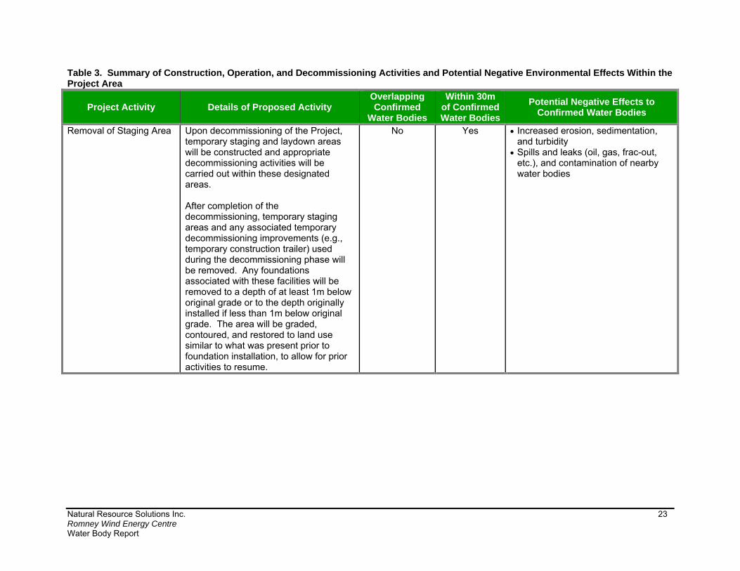
Removal of Staging Area Upon decommissioning of the Project, temporary staging and laydown areas will be constructed and appropriate decommissioning activities will be carried out within these designated areas. After completion of the decommissioning, temporary staging areas and any associated temporary decommissioning improvements (e.g., temporary construction trailer) used during the decommissioning phase will be removed. Any foundations associated with these facilities will be removed to a depth of at least 1m below original grade or to the depth originally installed if less than 1m below original grade. The area will be graded, contoured, and restored to land use similar to what was present prior to foundation installation, to allow for prior activities to resume.
No Yes Increased erosion, sedimentation, and turbidity
Spills and leaks (oil, gas, frac-out, etc.), and contamination of nearby water bodies

Natural Resource Solutions Inc. 24 Romney Wind Energy Centre Water Body Report
Potential negative effects and proposed mitigation measures for each of the Project
phases, including construction, operation, and decommissioning of project components
can be found in Table 4 below.
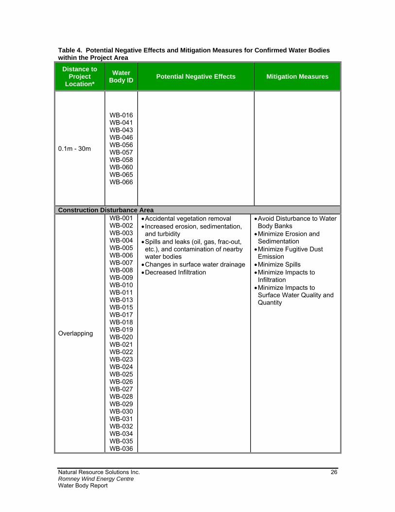
Table 4. Potential Negative Effects and Mitigation Measures for Confirmed Water Bodies within the Project Area
Distance to Project
Location*
Water Body ID
Potential Negative Effects Mitigation Measures
Wind Turbines (WT) Overlapping N/A N/A N/A 0.1m - 30m N/A
>30m - 120m
WB-001 WB-004 WB-005 WB-006 WB-011 WB-013 WB-015 WB-033 WB-055
Any potential negative effects have been mitigated by locating the project location more than 30m from the annual high-water mark of these water bodies
N/A
Access Road (AR)
Overlapping
WB-002 WB-003 WB-019 WB-020 WB-021 WB-022 WB-025 WB-026 WB-028 WB-029 WB-030 WB-031 WB-032 WB-036 WB-037 WB-038 WB-064
Accidental vegetation removal Increased erosion, sedimentation, and turbidity Fugitive dust emission Spills and leaks (oil, gas, frac-out, etc.), and contamination of nearby water bodies Changes in surface water drainage Decreased infiltration
Avoid Disturbance to Water Body Banks Minimize Impacts to Infiltration Minimize Erosion and Sedimentation Minimize Fugitive Dust Emissions Minimize Spills Minimize Impacts to Surface Water Quality and Quantity
0.1m - 30m
WB-008 WB-009 WB-010 WB-016 WB-034 WB-035 WB-042 WB-055 WB-065 WB-066
>30m - 120m WB-001 Any potential negative effects have N/A

Natural Resource Solutions Inc. 25 Romney Wind Energy Centre Water Body Report
Table 4. Potential Negative Effects and Mitigation Measures for Confirmed Water Bodies within the Project Area
Distance to Project
Location*
Water Body ID
Potential Negative Effects Mitigation Measures
WB-004 WB-005 WB-006 WB-011 WB-013 WB-015
been mitigated by locating the project location more than 30m from the annual high-water mark of this water body
Electrical Collector Lines (CL)
Overlapping
WB-001 WB-002 WB-003 WB-004 WB-005 WB-006 WB-008 WB-009 WB-010 WB-011 WB-013 WB-015 WB-017 WB-018 WB-019 WB-020 WB-021 WB-022 WB-025 WB-026 WB-028 WB-029 WB-030 WB-031 WB-032 WB-034 WB-035 WB-036 WB-037 WB-038 WB-039 WB-040 WB-042 WB-044 WB-045 WB-047 WB-049 WB-053 WB-054 WB-059 WB-064 WB-068
Accidental vegetation removal Increased erosion, sedimentation, and turbidity Fugitive dust emission Decreased infiltration Spills and leaks (oil, gas, frac-out, etc.), and contamination of nearby water bodies Reduced water quality (i.e. increased turbidity) Reduced groundwater discharge Removal of vegetation within the existing municipal road right-of-way
If dewatering of excavated trenches for underground electrical collector lines is required: Reduced groundwater discharge Reduced stream baseflow and upwelling Increased water temperatures Increased water quantity to receiving area or water body
Avoid Disturbance to Water Body Banks Minimize Erosion and Sedimentation Minimize Fugitive Dust Emission Minimize Spills Minimize Impacts to Infiltration Minimize Impacts to Surface Water Quality and Quantity Minimize Impacts to Groundwater Discharge
Natural Resource Solutions Inc. 26 Romney Wind Energy Centre Water Body Report
Table 4. Potential Negative Effects and Mitigation Measures for Confirmed Water Bodies within the Project Area
Distance to Project
Location*
Water Body ID
Potential Negative Effects Mitigation Measures
0.1m - 30m
WB-016 WB-041 WB-043 WB-046 WB-056 WB-057 WB-058 WB-060 WB-065 WB-066
Construction Disturbance Area
Overlapping
WB-001 WB-002 WB-003 WB-004 WB-005 WB-006 WB-007 WB-008 WB-009 WB-010 WB-011 WB-013 WB-015 WB-017 WB-018 WB-019 WB-020 WB-021 WB-022 WB-023 WB-024 WB-025 WB-026 WB-027 WB-028 WB-029 WB-030 WB-031 WB-032 WB-034 WB-035 WB-036
Accidental vegetation removal Increased erosion, sedimentation, and turbidity Spills and leaks (oil, gas, frac-out, etc.), and contamination of nearby water bodies Changes in surface water drainage Decreased Infiltration
Avoid Disturbance to Water Body Banks Minimize Erosion and Sedimentation Minimize Fugitive Dust Emission Minimize Spills Minimize Impacts to Infiltration Minimize Impacts to Surface Water Quality and Quantity
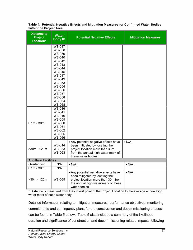
Natural Resource Solutions Inc. 27 Romney Wind Energy Centre Water Body Report
Table 4. Potential Negative Effects and Mitigation Measures for Confirmed Water Bodies within the Project Area
Distance to Project
Location*
Water Body ID
Potential Negative Effects Mitigation Measures
WB-037 WB-038 WB-039 WB-040 WB-042 WB-043 WB-044 WB-045 WB-047 WB-049 WB-053 WB-054 WB-056 WB-057 WB-058 WB-064 WB-068
0.1m - 30m
WB-016 WB-041 WB-046 WB-055 WB-060 WB-061 WB-062 WB-065 WB-066
>30m - 120m WB-014 WB-033 WB-063
Any potential negative effects have been mitigated by locating the project location more than 30m from the annual high-water mark of these water bodies
N/A
Ancillary Facilities Overlapping N/A N/A N/A 0.1m - 30m N/A
>30m - 120m WB-065
Any potential negative effects have been mitigated by locating the project location more than 30m from the annual high-water mark of these water bodies
N/A
* Distance is measured from the closest point of the Project Location to the average annual high water mark of each water body. Detailed information relating to mitigation measures, performance objectives, monitoring
commitments and contingency plans for the construction and decommissioning phases
can be found in Table 5 below. Table 5 also includes a summary of the likelihood,
duration and significance of construction and decommissioning related impacts following

Natural Resource Solutions Inc. 28 Romney Wind Energy Centre Water Body Report
the application of recommended mitigation measures. The majority of impacts are highly
unlikely and represent very rare events.

Natural Resource Solutions Inc. 29 Romney Wind Energy Centre Water Body Report
Table 5. Detailed Mitigation Measures, Performance Objectives, Monitoring Commitments, and Contingency Plans Recommended During the Construction and Decommissioning Phases of the Project
Mitigation Measure Details of Proposed Mitigation Measure Performance Objective(s)
Monitoring Commitment(s) Contingency Plan(s) Duration and Significance
of Impacts
Minimize Disturbance to Water Body Banks
Clearly delineate work area using erosion fencing or other suitable barrier to avoid accidental damage or removal of retained species.
Erect erosion fencing, or other barrier, to correspond to the disturbance area limits.
Place the erosion fencing, or other barrier, as far away as practical from the water body, and where possible from the average annual high-water mark of the water body (e.g. bankfull level or top of bank), or at the limit of natural vegetation surrounding the water body (i.e. natural riparian vegetation).
The on-site environmental monitor may also consider substituting other demarcating types for fencing, such as staking and flagging, where it is determined that there is no apparent risk to water bodies.
Locate directional drilling entry/exit shafts beyond the top of bank, at a distance that allows the minimum depth, as established by geotechnical studies, to be reached while below the water body. This distance should be agreed upon with regulatory agencies.
Operate construction equipment (i.e., cranes, back hoes etc.) in a manner that minimizes disturbance to the water body banks and natural vegetation within the riparian zone (i.e. natural vegetation on land within 30m of a water body) and stays outside of the water body and bank area.
Implement riparian planting after construction, as soon as weather permits, to stabilize water body banks and encourage rapid re-vegetation of disturbed soils. This will aid in preventing bank collapse and erosion, which, in turn, will minimize sedimentation and protect sensitive ecological functions that occur in water bodies.
If insufficient time is available in the growing season to establish vegetative cover, overwintering treatments could be applied, such as erosion control blankets, fiber matting, rock (i.e. large, clean angular rocks) reinforcement/armoring or equivalent to contain the site over the winter period. Plant vegetative cover as soon as is feasible in the next growing season, followed by maintenance and inspection.
To avoid accidental damage to water body
banks or removal of riparian vegetation adjacent to water
bodies.
Undertake regular monitoring of the work delineation fencing at a minimum frequency of once per month to ensure damage has not occurred to the fencing, and boundaries are clearly delineated and respected when construction is occurring within 30m of a water body.
Accidental damage to riparian vegetation may require re-planting of similar, native species, depending on the extent of damage incurred.
Unlikely Highly localized Temporary Not significant*
Minimize Spills
Clearly delineate the work area and place the fencing/barriers, as far away as practical from the average annual high-water mark of the water body (e.g. bankfull level or top of bank).
Locate drilling entry/exit shafts beyond the top of bank, at a distance that allows the minimum depth, as established by geotechnical studies, to be reached while below the water body. This distance should be agreed upon with regulatory agencies.
Develop a Spill Response Plan (SRP) prior to commencement of construction and train staff on appropriate procedures.
Keep emergency spill kits on site at all times. Keep contact information for the MOECC Spills Action Centre in
a designated area on-site. Dispose of waste material by authorized and approved off-site
vendors.
To prevent contamination of water bodies, minimize spills
Regular environmental monitoring will occur at least once every 2 weeks during the construction and decommissioning phase to ensure vehicle refueling and storage of chemicals is occurring more than 30m from any water body.
An on-site environmental monitor will be present when active directional drilling is occurring within 30m of a water body to identify frac-out, if it occurs.
In the event of a spill, notify the MOECC Spills Action Centre, immediately stop work, and ensure all efforts are made to completely remediate affected areas, especially prior to rain events.
If a spill occurs within a water body, the on-site environmental monitor will be notified and a follow-up site inspection will be conducted to document extent of degradation of the features, if any.
If degradation of a water body occurs as a result of the spill,
Highly unlikely Highly localized Temporary Not significant*

Natural Resource Solutions Inc. 30 Romney Wind Energy Centre Water Body Report
Table 5. Detailed Mitigation Measures, Performance Objectives, Monitoring Commitments, and Contingency Plans Recommended During the Construction and Decommissioning Phases of the Project
Mitigation Measure Details of Proposed Mitigation Measure Performance Objective(s)
Monitoring Commitment(s) Contingency Plan(s) Duration and Significance
of Impacts Securely store fuel, hazardous materials, and other construction
related materials more than 30m from the average annual high water mark of water bodies (e.g. bankfull level for intermittent/permanent watercourses).
Locate construction staging areas a minimum of 30m away from any water body.
Locate all vehicle refueling or washing stations a minimum of 30m from any water body.
Develop and implement an emergency ‘frac-out’ response plan including steps to contain, monitor and clean-up in response to the event.
Horizontal directional drilling should be executed at a minimum depth established by geotechnical studies to limit the potential impacts associated with the possibility of a ‘frac-out’.
appropriate contingency measures will be implemented, which may include re-establishing mitigation measures, habitat remediation, and/or seeding of banks and/or riparian areas in permanently damaged areas depending on the extent of degradation incurred.
If ‘frac-out’ occurs, immediately implement ‘frac-out’ contingency plan.
Minimize Impacts to Infiltration
Minimize the use of impervious surfaces, where practical, such as utilizing and contouring permeable surface material (i.e. gravel) to increase infiltration, and reduce surface water runoff.
Minimize vehicle traffic on exposed soils during site clearing, grubbing, grading and topsoil removal.
Confine construction equipment to designated, controlled vehicle access routes to minimize the potential for soil compaction.
Clearly delineate work area using erosion fencing or other suitable barrier to avoid accidental damage to water body banks or removal of riparian vegetation.
Place the erosion fencing, or other barrier, as far away as practical from the water body from the average annual high-water mark of the water body (e.g. bankfull level or top of bank), or at the limit of natural vegetation surrounding the water body (i.e. natural riparian vegetation).
Avoid construction during high volume rain events and substantial snow melt/thaw events, where possible, to avoid risk of soil compaction.
To minimize impacts to infiltration and changes
in surface drainage patterns and run-off
Undertake regular monitoring of the work delineation fencing at a minimum frequency of once per month to ensure damage has not occurred to the fencing, and boundaries are clearly delineated and respected when construction is occurring within 30m of a water body.
Regular environmental monitoring will occur during the construction and decommissioning phase.
No contingency plan required.
Likely minimal Localized Temporary Not significant*
Minimize Erosion and Sedimentation
Develop and implement an erosion and sediment control (ESC) plan.
Install, monitor, and maintain ESC measures (i.e. erosion fencing) around the Project Location for the duration of the construction or decommissioning activities, as identified within the ESC plan.
Clearly delineate work area using erosion fencing or other suitable barrier to avoid accidental damage or removal of retained species.
Erect erosion fencing, or other barrier, to correspond to the construction disturbance area limits and as far away as practical from the average annual high-water mark of the water body (e.g. bankfull level or top of bank), or at the limit of natural vegetation surrounding the water body (i.e. natural riparian vegetation).
Depending on site-specific conditions, such as steep topography and the presence of direct, or regular, surface water flow, the on-site environmental monitor may consider substituting other types of fencing or erosion and sediment control materials, when appropriate.
To avoid sedimentation or erosion of water
bodies.
Undertake regular monitoring and routine inspections to ensure proper installation of erosion control measures are in place.
Monitor sediment and erosion control measures, such as erosion fencing, and check dams daily in areas where work is taking place, and prior to, during, and after any storm events or significant snowmelt events.
During extended rain or snowmelt periods, monitoring erosion control measures daily.
Monitor sediment and erosion control measures monthly in areas where active construction is not occurring until the construction phase is complete.
Undertake regular monitoring of the
If deficiencies in sediment and erosion control measures are noted, the on-site environmental monitor will notify the general contractor and the Proponent and recommend remedial actions.
Silt fencing, or other applicable sediment and erosion control measures, that is not working properly will be corrected.
If sedimentation and erosion control measures fail and/or degradation of a water body occurs, appropriate contingency measures will be implemented, which may include re-establishing mitigation measures, water body clean out and/or bank stabilization, depending on the extent of
Highly unlikely Localized Temporary Not significant*

Natural Resource Solutions Inc. 31 Romney Wind Energy Centre Water Body Report
Table 5. Detailed Mitigation Measures, Performance Objectives, Monitoring Commitments, and Contingency Plans Recommended During the Construction and Decommissioning Phases of the Project
Mitigation Measure Details of Proposed Mitigation Measure Performance Objective(s)
Monitoring Commitment(s) Contingency Plan(s) Duration and Significance
of Impacts Utilize erosion blankets, silt fencing, straw bales, etc. to prevent
erosion and sediment from entering nearby water bodies. Store any stockpiled material more than 30m from the average
annual high-water mark of water bodies (e.g. bankfull level for intermittent/permanent watercourses).
Schedule grading to avoid times of high runoff volumes, wherever possible.
Where possible, time clearing, grubbing, and grading activities to avoid seasonally wet periods (i.e., spring and fall).
Collect directional drill cuttings as they are generated and placed in a soil bin or bag for off-site disposal.
Re-vegetate areas adjacent to water bodies, and directional drill entry/exit pits, to pre-construction conditions as soon as practical after construction activities are complete.
Schedule construction activities within 30m of a water body to occur within the low flow period of the late summer months, where possible, to avoid or minimize impacts.
Remove construction debris from the site and stabilize stockpiles, where practical, to prevent debris from entering the nearby water bodies.
Develop a Flood Response Plan (FRP) to deal with on-site flooding in order to mitigate any possible effects to the aquatic environment.
work delineation fencing at a minimum frequency of once per month to ensure damage has not occurred to the fencing, and boundaries are clearly delineated and respected when construction is occurring within 30m of a water body.
degradation incurred. Repair or replace any damaged
fencing immediately upon discovering an issue.
Minimize Impacts to Groundwater Discharge
Monitor rate of water pumping and timing to meet requirement of less than 50,000L per foundation site per day. If a volume of 50,000 L/day per foundation site is surpassed but is less than 400,000 L/day per foundation site, then registration on the MOECC’s Environmental Activity and Sector registry (EASR) for Water taking may be required. If the Project encounters extraordinary conditions (i.e. an infrequent storm event) that necessitate additional water takings (i.e. construction dewatering) beyond 400,000 L/day per foundation site, the local MOECC District Office will be contacted and consulted on direction on how to address the situation to allow the Project to proceed in a timely manner while maintaining environmental protection.
Restrict taking of groundwater and surface water during extreme low flow time periods.
Control quantity and quality of stormwater discharge using best management practices, and avoid direct discharge into wetlands, SWHs, and Generalized SWHs.
When discharging to a water body follow the ESC Plan and implement best management practices to avoid degradation of the water body.
If discharging to a municipal storm sewer system, ensure that water quality meets the objectives of the municipal storm sewer by-law prior to discharge.
Obtain water quality and turbidity samples prior to discharge to ensure the quality is suitable for discharge and will not result in an impact to the receiving water body. If the water quality is not suitable for discharge, identify alternate disposal locations or
To minimize direct impacts to water
quantity/quality in water bodies.
Monitor water levels of adjacent water body during groundwater dewatering activities to determine if activities are resulting in alteration of water levels within the water body.
Adhere to MOECC water quality Policy 1 and 2 Standards for discharging to water bodies.
Monitor end point of dewatering discharge for water quality and erosion (if dewatering).
Conduct daily erosion checks during discharge of water.
Monitor water quality (turbidity) prior to discharge, once a week thereafter or as described by agencies.
If impacts to groundwater discharge occur as a result of construction activities, the MNRF will be notified of appropriate contingency measures that will be implemented.
Highly unlikely Temporary Not significant*

Natural Resource Solutions Inc. 32 Romney Wind Energy Centre Water Body Report
Table 5. Detailed Mitigation Measures, Performance Objectives, Monitoring Commitments, and Contingency Plans Recommended During the Construction and Decommissioning Phases of the Project
Mitigation Measure Details of Proposed Mitigation Measure Performance Objective(s)
Monitoring Commitment(s) Contingency Plan(s) Duration and Significance
of Impacts undertake all practical measures to upgrade water quality prior to discharge.
Minimize Impacts to Surface Water Quality and Quantity
Clearly delineate work area using erosion fencing, or other barrier, to minimize potential impacts to water quality which may result from loss of riparian vegetation.
Erect erosion fencing, or other barrier, to correspond to the disturbance area limits.
Place the erosion fencing, or other barrier, as far away as practical from the average annual high-water mark of the water body (e.g. bankfull level or top of bank), or at the limit of natural vegetation surrounding the water body (i.e. natural riparian vegetation).
Locate drilling entry/exit shafts beyond the top of bank, at a distance that allows the minimum depth, as established by geotechnical studies, to be reached while below the water body. This distance should be agreed upon with regulatory agencies.
On site speed limits will be clearly posted, applied, and followed by construction staff to reduce fugitive dust.
Apply dust suppressants to unpaved areas when necessary to suppress dust, as determined by the on-site environmental monitor and general contractor. Application frequency will vary, but will be determined by site specific weather conditions, including recent precipitation, temperatures, and wind speeds. Install wind fences, where determined to be necessary by the on-site environmental monitor. Installation of these fences will depend on site-specific conditions, including wind speeds, topography, land cover, and the extent of surrounding natural wind breaks.
Restrict taking of groundwater and surface water during extreme low flow time periods.
If in-water work is required (e.g. for culvert installation and or electrical collector line installation), adhere to required timing windows confirmed through consultation with regulatory agencies, including the MNRF.
If required, perform in-water work in dry conditions, where possible.
Where work in dry-conditions is not possible, short-term, isolated surface water dewatering is required.
Prior to dewatering, isolate the work area with the installation of a temporary water containment structure. The structure should form an impermeable enclosure that will prevent debris and sediment from escaping into the surrounding water body.
Construct a by-pass channel to maintain flow through the water body and prevent back flooding, which could ultimately overtop the water containment structure.
Obtain applicable permits, where required, for surface water dewatering.
Prior to surface water dewatering, obtain a Fish Salvage Plan, prepared by a qualified fisheries biologist and relocate fish to a
To prevent degradation of surface water quality and changes in water
quantity related to construction activities.
Follow the ESC Plan monitoring commitments.
When discharging to a different drainage feature, monitor general water quality parameters as required to meet MOECC Policy 1 and 2 standards for discharging to a water body. In addition, measure turbidity levels of water to be discharged. If the water quality is not suitable for discharge, identify alternate disposal locations or undertake all practical measures to upgrade water quality prior to discharge.
Monitor water levels immediately before and during dewatering activities, to determine if dewatering activities are resulting in alteration of water levels within the water body.
Monitor the discharge location for dewatering activities to ensure erosion and sedimentation of the receiving water body is not occurring.
Monitor erosion and sediment control systems frequently for effectiveness at a minimum of once daily during discharge activities. Repair deficient controls in a timely manner and using an adaptive management approach when deemed appropriate.
Monitor by-pass channel (if applicable) daily to ensure it is functioning appropriately and water is flowing through as designed.
Undertake regular monitoring of the work delineation fencing at a minimum frequency of once per month to ensure damage has not occurred to the fencing, and boundaries are clearly delineated and respected when construction is occurring within 30m of a water body.
If reduced water quality (i.e. increased turbidity) as a result of construction activities is observed, the MNRF will be notified of appropriate contingency measures that will be implemented.
Repair or replace any damaged fencing immediately upon discovering an issue.
Unlikely Localized Temporary Not significant*
Natural Resource Solutions Inc. 33 Romney Wind Energy Centre Water Body Report
Table 5. Detailed Mitigation Measures, Performance Objectives, Monitoring Commitments, and Contingency Plans Recommended During the Construction and Decommissioning Phases of the Project
Mitigation Measure Details of Proposed Mitigation Measure Performance Objective(s)
Monitoring Commitment(s) Contingency Plan(s) Duration and Significance
of Impacts suitable location, preferably downstream and away from the construction area, as detailed in the plan.
Install an in-stream sediment filter (e.g. Siltsoxx or Filtersoxx) downstream of water containment structure. Dewatering discharge should be dissipated (i.e. splash pads, sand bags, hay bales etc.) and may require splitting discharge to more than one location.
Dewatering discharge rates should be evaluated as to not result in erosion and sedimentation to receiving water body.
If discharging to a municipal storm sewer system, ensure that water quality meets the objectives of the municipal storm sewer by-law prior to discharge.
Re-vegetate disturbed area adjacent to water bodies as soon as practical after construction activities are complete.
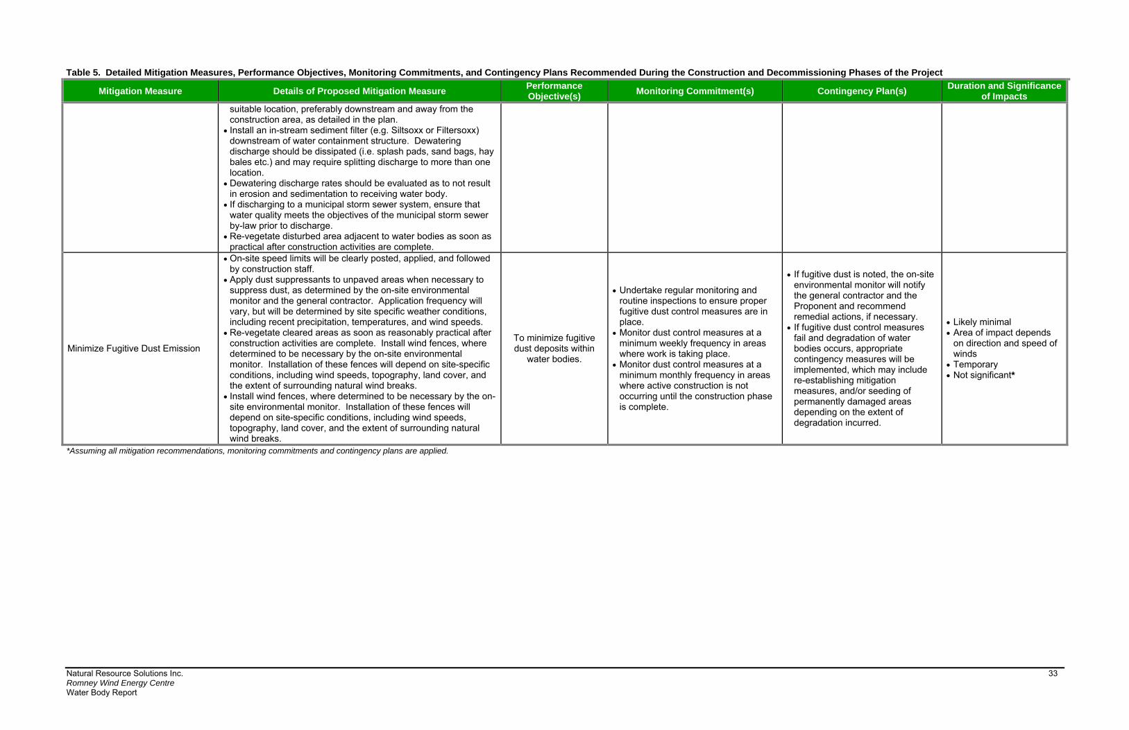
Minimize Fugitive Dust Emission
On-site speed limits will be clearly posted, applied, and followed by construction staff.
Apply dust suppressants to unpaved areas when necessary to suppress dust, as determined by the on-site environmental monitor and the general contractor. Application frequency will vary, but will be determined by site specific weather conditions, including recent precipitation, temperatures, and wind speeds.
Re-vegetate cleared areas as soon as reasonably practical after construction activities are complete. Install wind fences, where determined to be necessary by the on-site environmental monitor. Installation of these fences will depend on site-specific conditions, including wind speeds, topography, land cover, and the extent of surrounding natural wind breaks.
Install wind fences, where determined to be necessary by the on-site environmental monitor. Installation of these fences will depend on site-specific conditions, including wind speeds, topography, land cover, and the extent of surrounding natural wind breaks.
To minimize fugitive dust deposits within
water bodies.
Undertake regular monitoring and routine inspections to ensure proper fugitive dust control measures are in place.
Monitor dust control measures at a minimum weekly frequency in areas where work is taking place.
Monitor dust control measures at a minimum monthly frequency in areas where active construction is not occurring until the construction phase is complete.
If fugitive dust is noted, the on-site environmental monitor will notify the general contractor and the Proponent and recommend remedial actions, if necessary.
If fugitive dust control measures fail and degradation of water bodies occurs, appropriate contingency measures will be implemented, which may include re-establishing mitigation measures, and/or seeding of permanently damaged areas depending on the extent of degradation incurred.
Likely minimal Area of impact depends
on direction and speed of winds
Temporary Not significant*
*Assuming all mitigation recommendations, monitoring commitments and contingency plans are applied.

Natural Resource Solutions Inc. 34 Romney Wind Energy Centre Water Body Report
Detailed information relating to mitigation measures, performance objectives, monitoring
commitments and contingency plans for the operational phase can be found in Table 6 below.
Table 6 also includes a summary of the likelihood, duration and significance of operation related
impacts following the application of recommended mitigation measures. The majority of impacts
are highly unlikely and represent very rare events.

Natural Resource Solutions Inc. 35 Romney Wind Energy Centre Water Body Report
Table 6. Detailed Mitigation Measures, Performance Objectives, Monitoring Commitments, and Contingency Plans Recommended During the Operational Phase of the Project
Mitigation Measure Details of Proposed Mitigation Measure Performance Objective(s)
Monitoring Commitment(s) Contingency Plan(s) Duration and Significance of
Impacts
Minimize Erosion and Sedimentation
Schedule grading to avoid times of high runoff volumes, wherever possible.
Where possible, time vegetation clearing or maintenance activities to avoid seasonally wet periods (i.e., spring and fall) and to avoid times of high runoff volumes, wherever practical.
To minimize potential impacts associated with
erosion and sedimentation of water
bodies.
No monitoring plan required.
Accidental damage to riparian vegetation may require re-planting of similar, native species, depending on the extent of damage incurred.
Highly unlikely Localized Temporary Not significant*
Minimize Spills
Develop a Spill Response Plan (SPRP) prior to commencement of construction and train staff on appropriate procedures.
Keep emergency spill kits on site at all times. Keep contact information for the MOECC Spills
Action Centre in a designated area on-site. Dispose of waste material by authorized and
approved off-site vendors. Store hazardous materials in designated areas. Locate all maintenance activities, vehicle refueling or
washing, as well as the storage of chemicals and heavy equipment a minimum of 30m away from water bodies.
Prevent contamination of water bodies.
Minimize spills near water
bodies.
No monitoring plan required.
In the event of a spill, notify the MOECC Spills Action Centre, immediately stop work, and ensure all efforts are made to completely remediate affected areas, especially prior to rain events.
If degradation of a water body occurs as a result of the spill, appropriate contingency measures will be implemented, which may include re-establishing mitigation measures, habitat remediation, and/or seeding of banks and/or riparian areas in permanently damaged areas depending on the extent of degradation incurred.
Highly unlikely Highly localized Temporary Not significant*
*Assuming all mitigation recommendations, monitoring commitments and contingency plans are applied.

Natural Resource Solutions Inc. 36 Romney Wind Energy Centre Water Body Report
6.3 Summary of Monitoring Activities
An adaptive management approach to the protection of water bodies requires regular
site inspections and monitoring by a designated on-site Environmental Monitor(s) (EM).
Understanding the condition of the natural ecosystem throughout all phases of the
Project will form the basis upon which to consider altering construction methods,
environmental protection measures, and monitoring programs. Ultimately, any
determination related to the application of mitigation and contingency measures will be
informed by ongoing analyses of monitoring data, and rely on the experience and
judgment of the on-site EM in consultation with the LTVCA, MNRF, Ministry of the
Environment and Climate Change (MOECC) and Fisheries and Oceans Canada (DFO)
as regulatory agencies.
Active construction monitoring will be required at all locations where drainage features
and water bodies are located within 120m of the Project Location. General
recommended monitoring activities are summarized above in Table 5 for construction-
related impacts and Table 6 for operation-related impacts.

Natural Resource Solutions Inc. 37 Romney Wind Energy Centre Water Body Report
7.0 Summary and Conclusions
A detailed assessment of the water bodies within and adjacent to the proposed Project
occurred through a detailed records review and site investigation conducted by NRSI
biologists (NRSI 2017).
Through the completion of site-specific assessments, NRSI confirmed the presence of
32 water bodies within the Project Area, all of which were identified as permanent or
intermittent drainage features. Of these 32 water bodies, 23 were identified as crossing
the Project Location. Each of the crossing locations involves at least one type of project
component, but may involve multiple project components (i.e. access road and
underground or overhead electrical collector lines). Of the remaining water bodies, 6 are
found within 30m and 3 are found between 31-120m of the Project Location at their
closest point, without specifically overlapping the Project Location.
No lakes, lake trout lakes or seepage areas were identified within the Project Area.
If recommended mitigation measures are employed as described in this report, no
significant impacts are anticipated on the identified water bodies as a result of the
Project.

Natural Resource Solutions Inc. 38 Romney Wind Energy Centre Water Body Report
8.0 References DNV-GL. 2017a. Romney Wind Energy Centre: Construction Plan Report. September
2017. DNV-GL. 2017b. Romney Wind Energy Centre: Design and Operations Report.
September 2017. DNV-GL. 2017c. Romney Wind Energy Centre: Decommissioning Plan Report. July
2017. DNV-GL. 2017d. Romney Wind Energy Centre: Project Description Report. July 2017. Ministry of the Environment. 2013. Technical Guide to Renewable Energy Approvals. Natural Resource Solutions Inc. (NRSI). 2017. Romney Wind Energy Centre: Water
Body Assessment. September 2017.

Natural Resource Solutions Inc. Maps
Map 1
Project Area and Natural Features

! ! ! ! ! ! ! ! ! ! ! ! ! ! ! ! ! ! ! ! ! ! ! ! ! ! ! ! ! ! ! ! ! ! ! ! ! ! ! ! ! ! ! ! ! ! ! !
!
!
!
!
!
!
!
!
!
!
!
!!
!!
!!
!!
!!
!!
!!
!!
!!
!!
!!
!!
!!
!!
!!
!!
!!
!!
!!
!!
!!
!!
!!
!!
!!
!!
!!
!!
!
!
!
!
!
!
!
!
!
!
!
!
!
!
!
!
!
!
!
!
!
!
!
!
!
! ! ! ! ! ! ! ! ! ! ! ! ! ! ! ! ! ! ! ! ! ! ! ! ! ! ! ! ! ! ! ! ! ! ! ! ! ! ! ! ! ! ! ! ! ! ! !
!
!
!
!
!
!
!
!
!
!
!
!!
!!
!!
!!
!!
!!
!!
!!
!!
!!
!!
!!
!!
!!
!!
!!
!!
!!
!!
!!
!!
!!
!!
!!
!!
!!
!!
!!
!
!
!
!
!
!
!
!
!
!
!
!
!
!
!
!
!
!
!
!
!
!
!
!
!
!
!
!
!
!
!
!
!
!!
!
!
!
!
!
!
!
!
!
!
!
!
!
!
!
!
!
!
!
!
!
!
!
!
!
!
!
!
!
!
!
!
!
!
!
!
!
!
!
!
!
!!
!
!
!
!
!
!
!
!
!
!!
!
!
!
!
!
!
!
!
!
!
!
!
!
!
!
!
!
!!
!
! ! ! ! ! ! ! ! !
!
!
!
!
!
!
!
!
!
!
!
!
!
!
!!!!!
!!
!!
!!
!!
!!
!!
!!
!!
!!
!!
!!
!!
!!
!!
!!
!!!!
!!
!!
!!
!!
!!
!!
!!
!!
!!
!!
!!
!!
!!
!!
!!
!
!
!
!
!
!
! !
!
!!
!
!
!
!
!
!
!
!
!
!
!
!
!
!
!
!
!
!
!
!
!
!
!
!
!
!
!
!
!
!
!
!
!
!
!
!
!
!
!
!
!
!
!
!
!
!
!
!
!
!
!
!
!
!
!
!
!
!
!
!
!
!
!
!
!
!
!
!
!
!
!
!
$+
Comber
Lake Erie
Tilbur y Cre ek
Tremblay Creek
Baptiste Creek
Wes t T
woCr
e eks
East T
woCr
eeks
Big Cr
eek
MAIN ST
S MIDDLE
RD
CO UNTY RD 46
GRACEY SIDERD
GO RE RD
CO N RD 7
CO N RD 5
WHEATLEY RD
TALBOT TRA
IL
ERIE ST N
GRAY LINE
CO N RD 6HWY 77
N MIDDLE
RD
CO UNTY RD 8
CO ATSWO RTH RD
GO O DREAU LINE
MIDDLELINE
KING & WHITTLE RD
GRO VE RD
Q UINN LINE
COX LINE
VANEDIE RDHERMAN LINE
CARLESS RD
HORNICK LINE
OAK RD
BOWERS LINE
CO N RD 10
CO N RD 11
COUNTY RD 37
ZIO N RD
5TH CONC LINE
BLUFF LINE
MERSEA12
RD
RICHARDSO N SIDERD
CAMPBELL RD
DEPOT RD
KEMP LINE
MERSEA 8 RD
CO UNTY RD 14
MERSEA 10 RD
MERSEA 11 RD
ROSEDALE LINE
MERSEA 7RD
6TH CONC LINE
HWY401
4TH CONC LINE
CO N RD 9
CO N RD 8
3RD CONC LINE
2ND CO N
C LINET2
T11T6
T5T16
T8
T9
T4
T14
T15
T17
T10
T1
T3
T7
T12
T13
A1
372000
372000
375000
375000
378000
378000
381000
381000
384000
384000
387000
387000
390000
390000
4663
000
4663
000
4666
000
4666
000
4669
000
4669
000
4672
000
4672
000
4675
000
4675
000
4678
000
4678
000 Romney WEC
Legend! Utility Lin e
Ra ilwa yHighwa y
Prim a ry Roa d
Secon da ry Roa dProject Components
Project AreaProject Loca tion
Proposed Turbin e
$+ Proposed Meteorologica l Tower ! ! Proposed Collection Lin e
Proposed Access Roa dProposed O &M Buildin g
Natural FeaturesPerm a n en t Wa tercourse
In term itten t Wa tercourseO pen Wa terWooded Area
Project Area and Natural Features
Map 1
Ma p Produced by Na tura l Resource Solution s In c. This m a p is proprieta ry a n d con fiden tia l a n d m ust n ot be duplica ted or distributed by a n y m ea n s withoutexpress written perm ission of NRSI. Da ta provided by MNRF© Copyright: Q ueen ’s Prin ter O n ta rio.
¢0 1 2 3 4Kilom eters
Pa th: X:\1736_ Rom n ey_ WEC\NRSI_ 1736_ WB_Ma p1_ ProjectArea _ Na tura lFea tures_ 65K_ 2017_ 06_ 28_KEF.m xd
Project:1736CDa te: Jun e 28, 2017
NAD83 - UTM Zon e 17Size: 11x17"
1:68,000
Key MapLake Erie
Lake St. Clair
TOWN OFKINGSVILLE
MUNICIPALITYOF LEAMINGTON
TOWN OFLAKESHORE
MUNICIPALITY OFCHATHAM-KENT
HWY 77
KINGSHWY 3
HWY401
Deerbrook
RuscomStationSouth
Woodslee
St. JoachimFletcher
Tilbury
Wheatley
Staples

Natural Resource Solutions Inc. Maps
Map 2 Water Body Assessment Key Map

! ! ! ! ! ! ! ! ! ! ! ! ! ! ! ! ! ! ! ! ! ! ! ! ! ! ! ! ! ! ! ! ! ! ! ! ! ! ! ! ! ! ! ! ! ! ! !
!
!
!
!
!
!
!
!
!
!
!
!!
!!
!!
!!
!!
!!
!!
!!
!!
!!
!!
!!
!!
!!
!!
!!
!!
!!
!!
!!
!!
!!
!!
!!
!!
!!
!!
!!
!
!
!
!
!
!
!
!
!
!
!
!
!
!
!
!
!
!
!
!
!
!
!
!
!
! ! ! ! ! ! ! ! ! ! ! ! ! ! ! ! ! ! ! ! ! ! ! ! ! ! ! ! ! ! ! ! ! ! ! ! ! ! ! ! ! ! ! ! ! ! ! !
!
!
!
!
!
!
!
!
!
!
!
!!
!!
!!
!!
!!
!!
!!
!!
!!
!!
!!
!!
!!
!!
!!
!!
!!
!!
!!
!!
!!
!!
!!
!!
!!
!!
!!
!!
!
!
!
!
!
!
!
!
!
!
!
!
!
!
!
!
!
!
!
!
!
!
!
!
!
!
!
!
!
!
!
!
!
!!
!
!
!
!
!
!
!
!
!
!
!
!
!
!
!
!
!
!
!
!
!
!
!
!
!
!
!
!
!
!
!
!
!
!
!
!
!
!
!
!
!
!!
!
!
!
!
!
!
!
!
!
!!
!
!
!
!
!
!
!
!
!
!
!
!
!
!
!
!
!
!!
!
! ! ! ! ! ! ! ! !
!
!
!
!
!
!
!
!
!
!
!
!
!
!
!!!!!
!!
!!
!!
!!
!!
!!
!!
!!
!!
!!
!!
!!
!!
!!
!!
!!!!
!!
!!
!!
!!
!!
!!
!!
!!
!!
!!
!!
!!
!!
!!
!!
!
!
!
!
!
!
! !
!
!!
!
!
!
!
!
!
!
!
!
!
!
!
!
!
!
!
!
!
!
!
!
!
!
!
!
!
!
!
!
!
!
!
!
!
!
!
!
!
!
!
!
!
!
!
!
!
!
!
!
!
!
!
!
!
!
!
!
!
!
!
!
!
!
!
!
!
!
!
!
!
!
!
$+
Comber
Lake Erie
Tremblay Creek
Baptiste Creek
Map 3 - 5
Map 3 - 1
Map 3 - 2
Map 3 - 3
Map 3 - 4
MAIN ST
S MIDDLE
RD
CO UNTY RD 46
GRACEY SIDERD
GO RE RD
CO N RD 7
CO N RD 5
WHEATLEY RD
TALBOT TRA
IL
ERIE ST N
GRAY LINE
CO N RD 6HWY 77
N MIDDLE
RD
CO UNTY RD 8
CO ATSWO RTH RD
GO O DREAU LINE
MIDDLELINE
KING & WHITTLE RD
GRO VE RD
Q UINN LINE
COX LINE
VANEDIE RD
HERMAN LINE
CARLESS RD
HORNICK LINE
OAK RD
BOWERS LINE
CO N RD 10
CO N RD 11
COUNTY RD 37
ZIO N RD
5TH CONC LINE
BLUFF LINE
MERSEA12
RD
RICHARDSO N SIDERD
CAMPBELL RD
DEPOT RD
KEMP LINE
MERSEA 8 RD
CO UNTY RD 14
MERSEA 10 RD
MERSEA 11 RD
ROSEDALE LINE
MERSEA 7RD
6TH CONC LINE
HWY401
4TH CONC LINE
CO N RD 9
CO N RD 8
3RD CONC LINE
2ND CO N
C LINET2
T11T6
T5T16
T8
T9
T4
T14
T15
T17
T10
T1
T3
T7
T12 T13
A1
372000
372000
375000
375000
378000
378000
381000
381000
384000
384000
387000
387000
390000
390000
4663
000
4663
000
4666
000
4666
000
4669
000
4669
000
4672
000
4672
000
4675
000
4675
000
4678
000
4678
000 Romney WEC
LegendMa p Exten t
! Utility Lin eRa ilwa yHighwa y
Prim a ry Roa d
Secon da ry Roa dProject Components
Project AreaProject Loca tion
Proposed Turbin e
$+ Proposed Meteorologica l Tower! ! Proposed Collection Lin e
Proposed Access Roa dProposed O &M Buildin g
Natural FeaturesPerm a n en t Wa tercourse
In term itten t Wa tercourseO pen Wa ter
Key Map
Map 2
Ma p Produced by Na tura l Resource Solution s In c. This m a p is proprieta ry a n d con fiden tia l a n d m ust n ot be duplica ted or distributed by a n y m ea n s withoutexpress written perm ission of NRSI. Da ta provided by MNRF© Copyright: Q ueen ’s Prin ter O n ta rio.
¢0 1 2 3 4Kilom eters
Pa th: X:\1736_ Rom n ey_ WEC\NRSI_ 1736_ WB_Ma p2_ KeyMa p_65K_ 2017_ 06_ 28_ KEF.m xd
Project:1736CDa te: Jun e 28, 2017
NAD83 - UTM Zon e 17Size: 11x17"
1:68,000
Key MapLake Erie
Lake St. Clair
TOWN OFKINGSVILLE
MUNICIPALITYOF LEAMINGTON
TOWN OFLAKESHORE
MUNICIPALITY OFCHATHAM-KENT
HWY 77
KINGSHWY 3
HWY401
Deerbrook
RuscomStationSouth
Woodslee
St. JoachimFletcher
Tilbury
Wheatley
Staples

Natural Resource Solutions Inc. Maps
Maps 3-1 to 3-5 Water Body Assessment Maps
________________________________________________________________

!!
!!
!!
!!
!!
!!
!!
!!
!!
!!
!!
!!
!!
!!
!!
!!
!!
!!
!!
!!
!!
!!
!!
!!
!!
!!
!!
!!
!!
!!
!!
!!
!!
!!
!!
!!
!!
!!
!!
!!
!!
!!
!!
!!
!!
!!
!!
!!
!!
!!
!!
!!
!!
!!
!!
!!
!!
!!
!!
!!
!!
!!
!!
!!
!!
!!
!!
!!
!!
!!
!!
!!
!!
!!
!!
!!
!
!!
!!
!!
!!
!!
!!
!!
!!
!!
!!
!!
!!
!!
!!
!!
!!
!!
!!
!!
!!
!!
!!
!!
!!
!!
!!
!!
!!
!!
!!
!!
!!
!!
!!
!!
!!
!!
!!
!!
!!
!!
!!
!!
!!
!!
!!
!!
!!
!!
!!
!!
!!
!!
!!
!!
!!
!!
!!
!!
!!
!!
!!
!!
!!
!!
!!
!!
!!
!!
!!
!!
!!
!!
!!
!!
!!
!
!
! !
!
!
!
!
!
!
!
!
!
!
!
!
!
!
!
!
!!!!!!!!!!!!!!!!!
!!
!!
!!
!!
!!
!!
!!
!!
!!
!!
!!
!!
!!
!!
!!
!!
!!
!!
!!
!!
!!
!!
!!
!!
!!
!!
!!
!!
!!
!!
!!
!!
!!
!!
!!
!!
!!
!!
!!
!!
!!
!!
!!
!!
!!
!!
!!
!!
!!
!!
!!
!
!!!!!!!
!
!!!!!!!!!!!!!
!!
!!
!!
!!
!!
!!
!!
!!
!!
!!
!!
!!
!!
!!
!!
!!
!!
!!
!!
!!
!!
!!
!!
!!
!!
!!
!!
!!
!!
!!
!!
!!
!!
!!
!!
!!
!!
!!
!!
!!
!!
!!
!!
!!
!!
!!
!!
!!
!!
!!
!!
!!
!
!!!!!!!
")
")
")
")
!(
Tilbury
CO U NTY RD 46
S M IDDLE RD
GO RE RD
CO N RD 7
CO N RD 5
M IDDLE LI
NE
ELIZAB
ETHST
QUEEN ST SJEFF
REYST
W
HOMESTEA
DS DR
WHEATLEY RD
GRAY L
INE
RICHARDSO N SIDERD
ROSEDALE LINE
CO N RD 8
Big Creek
WB-043
NWB-022
NWB-023
NWB-024
NWB-039
Big Creek
Til buryCreek
378000
378000
380000
380000
4676
000
4676
000
4678
000
4678
000
Legend! U tility Line
RailwayPrimary Road
Secondary RoadProject Components
Project AreaProject Location
! ! Proposed Collection LineProposed Access Road
Aquatic FeaturesPermanent WatercourseConstructed DrainO pen Water
Water Body Assessment!( Water Body Location (WB)
") Non-Water Body Location (NWB)
Map 3 - 1
M ap Produced by Natural Resource Solutions Inc. This map is proprietary and confidential and must not be duplicated or distributed by any means withoutexpress written permission of NRSI. Data provided by M NRF© Copyright: Queen’s Printer O ntario. Imagery: DNV GL (2016) & First Base Solutions (2010)
¢0 400 800 1,200M eters
Path: X:\1736_Romney_WEC\NRSI_1736_WB_M ap3-1toM ap3-5_WaterBodyAssessment_19K_2017_06_29_KEF.mxd
Project:1736Date: June 29, 2017
NAD83 - U TM Z one 17Size: 11x17"
1:18,500
Romney WECWater Body Assessment
! ! ! ! ! ! ! ! ! ! ! ! !!
!
!!
!!
!!
!!
!!
!!
!!
!!
!
!
!
!
!
! ! ! ! ! ! ! ! ! ! ! ! !!
!
!!
!!
!!
!!
!!
!!
!!
!!
!
!
!
!
!
!
!
!
!!!!!!!!!!!!!
Tillbury Key Map
Lake ErieTALB
O TTRAI
L
HWY 77
CO U NTY R
D 46
GRACEY SIDERD
CO N RD 7
CO N RD 5
WHEATLEY RD
HERM AN LINE
GRAY LINE
CO U NTY RD 8
OAK RD
CAM PBELL RD
QUINN LINE VANEDIE RD
HORNICK LINE
CO N RD 10CO N RD 11
MERSEA12RD
KEMP LINE
M ERSEA 7RD
6TH CONC LINE
CO N RD 9
CO N RD 8
HWY 401
M ERSEA 8RD
CO U NTY RD 14
M ERSEA 10RD
M ERSEA11RD
3RD CONC LINE
ZIO N RD
CO ATSWO RTH RD
Comber
Staples

!!
!!
!!
!!
!!
!!
!!
!!
!!
!!
!!
!!
!!
!!
!!
!!
!!
!!
!!
!!
!!
!!
!!
!!
!!
!!
!!
!!
!!
!!
!!
!!
!!
!!
!!
!!
!!
!!
!!
!!
!!
!!
!!
!!
!!
!!
!!
!!
!!
!!
!!
!!
!!
!!
!!
!!
!!
!!
!!
!!
!!
!!
!!
!!
!!
!!
!!
!!
!!
!!
!!
!!
!!
!!
!!
!!
!!
!!
!!
!!
!!
!!
!
!!
!!
!!
!!
!!
!
! ! ! ! ! ! ! ! ! ! ! ! ! ! ! ! ! ! ! ! ! ! ! ! ! ! ! ! ! ! ! !
!
!
!
!
!
!
!
!
!
!
!
!
!
! !
!
!
!
!
!
!
!
!
!
!
!
!
!
!
!
!
!!!!!!!!!!!!!!!!!
!!
!!
!!
!!
!!
!!
!!
!!
!!
!!
!!
!!
!!
!!
!!
!!
!!
!!
!!
!!
!!
!!
!!
!!
!!
!!
!!
!!
!!
!!
!!
!!
!!
!!
!!
!!
!!
!!
!!
!!
!!
!!
!!
!!
!!
!!
!!
!!
!!
!!
!!
!
!!!!!!!
!
!!!!!!!!!!!!!
!!
!!
!!
!!
!!
!!
!!
!!
!!
!!
!!
!!
!!
!!
!!
!!
!!
!!
!!
!!
!!
!!
!!
!!
!!
!!
!!
!!
!!
!!
!!
!!
!!
!!
!!
!!
!!
!!
!!
!!
!!
!!
!!
!!
!!
!!
!!
!!
!!
!!
!!
!!
!
!!!!!!!
!
!
!
!
!
!
!
!
!
!
!
!
!
!
!
!
!
!
!
!
!
!
!
!
!
!
!
!
!
!
!
!
!
!
!
!
!
!
!
!
!
!
!
!
!
!
!
!
!
!
!
!
!
!
!
!
!
!
!
!
!
!
!
!
!
!
!
!
!
!
!
!
!
!
!
!
!
!
!
!
!
!
!
!
!
!
!
!
!
!
!
!
!
!
!
!
!
!
!
!
!
!
!
!
!
!
!
!
!
!
!
!
!
!
!
!
!
!!!
")
")
")
")
")")
")
")
")")")
")
")
!(
!(
!(
!(
!(!(
!(
!(
!(
!(
!(
!(
!(
!(
!(
!(
!(
WHEATLEY RD
TILBURY W & ROM NEY RD
6TH CONC LINE
GO O DREAU LINE
CO N RD 10
CO N RD 11
CAM PBELL RD
RICHARDSO N SIDERD
CO N RD 9
T17
T1
A1
WB-019
WB-020
WB-021
WB-033
WB-044WB-045WB-046
WB-047
WB-049
WB-053WB-054
WB-055
WB-056
WB-057
WB-058
WB-059
WB-064
NWB-010
NWB-011
NWB-012
NWB-014NWB-025
NWB-026
NWB-027
NWB-028
NWB-030NWB-031
NWB-032
NWB-040
NWB-043
Big Creek
376000
376000
378000
378000
380000
380000
4670
000
4670
000
4672
000
4672
000
4674
000
4674
000
LegendPrimary Road
Secondary RoadProject Components
Project AreaProject Location
Proposed Turbine
! ! Proposed Collection LineProposed Access Road
Aquatic FeaturesPermanent WatercourseM unicipal DrainConstructed DrainO pen Water
Water Body Assessment!( Water Body Location (WB)
") Non-Water Body Location (NWB)
Map 3 - 2
M ap Produced by Natural Resource Solutions Inc. This map is proprietary and confidential and must not be duplicated or distributed by any means withoutexpress written permission of NRSI. Data provided by M NRF© Copyright: Queen’s Printer O ntario. Imagery: DNV GL (2016) & First Base Solutions (2010)
¢0 400 800 1,200M eters
Path: X:\1736_Romney_WEC\NRSI_1736_WB_M ap3-1toM ap3-5_WaterBodyAssessment_19K_2017_06_29_KEF.mxd
Project:1736Date: June 29, 2017
NAD83 - U TM Z one 17Size: 11x17"
1:18,500
Romney WECWater Body Assessment
! ! ! ! ! ! ! ! ! ! ! ! !!
!
!!
!!
!!
!!
!!
!!
!!
!!
!
!
!
!
!
! ! ! ! ! ! ! ! ! ! ! ! !!
!
!!
!!
!!
!!
!!
!!
!!
!!
!
!
!
!
!
!
!
!
!!!!!!!!!!!!!
Tillbury Key Map
Lake ErieTALB
O TTRAI
L
HWY 77
CO U NTY R
D 46
GRACEY SIDERD
CO N RD 7
CO N RD 5
WHEATLEY RD
HERM AN LINE
GRAY LINE
CO U NTY RD 8
OAK RD
CAM PBELL RD
QUINN LINE VANEDIE RD
HORNICK LINE
CO N RD 10CO N RD 11
MERSEA12RD
KEMP LINE
M ERSEA 7RD
6TH CONC LINE
CO N RD 9
CO N RD 8
HWY 401
M ERSEA 8RD
CO U NTY RD 14
M ERSEA 10RD
M ERSEA11RD
3RD CONC LINE
ZIO N RD
CO ATSWO RTH RD
Comber
Staples

!
!
!
!
!
!
!
!
!
!
!
!
!
!
!
!
!
!
!
!
!
!
!
!
!
!
!
!
!
!
!
!
!
!
!
!
!
!
!
!
!
!
!
!
!
!
!
!
!
!
!
!
!
!
!
!
!
!
!
!
!
!
!
!
!
!
!
!
!
!
!
!
!
!
!
!
!
!
!
!
!
!
!
!
!
!
!!
!!
!!
!!
!!
!
! ! ! ! ! ! ! ! ! ! ! ! ! ! ! ! ! ! ! ! ! ! ! ! ! ! ! ! ! ! ! !
!
!
!
!
!
!
!
!
!
!
!
!
!
! !
!
!
!
!
!
!
!
!
!
!
!
!
!
!
!
!
!!!!!!!!!!!!!!!!!
!!
!!
!!
!!
!!
!!
!!
!!
!!
!!
!!
!!
!!
!!
!!
!!
!!
!!
!!
!!
!!
!!
!!
!!
!!
!!
!!
!!
!!
!!
!!
!!
!!
!!
!!
!!
!!
!!
!!
!!
!!
!!
!!
!!
!!
!!
!!
!!
!!
!!
!!
!
!!!!!!!
!
!!!!!!!!!!!!!
!!
!!
!!
!!
!!
!!
!!
!!
!!
!!
!!
!!
!!
!!
!!
!!
!!
!!
!!
!!
!!
!!
!!
!!
!!
!!
!!
!!
!!
!!
!!
!!
!!
!!
!!
!!
!!
!!
!!
!!
!!
!!
!!
!!
!!
!!
!!
!!
!!
!!
!!
!!
!
!!!!!!!
!
!
!
!
!
!
!
!
!
!
!
!
!
!
!
!
!
!
!
!
!
!
!
!
!
!
!
!
!
!
!
!
!
!
!
!
!
!
!
!
!
!
!
!
!
!
!
!
!
!
!
!
!
!
!!
!
!
!
!
!
!
!
!
!
!
!
!
!
!
!
!
!
!
!
!
!
!
!
!
!
!
!
!
!
!
!
!!
!
!
!
!
!
!
!
!
!
!
!
!
!
!
!
!
!
!
!
!
!
!
!
!
!
!
!
!
!
!
!
!
!
!
!
!
!
!
!
!
!
!
!
!
!
!
!
!
!
!
!
!
!
!
!
!
!
!
!
!
!
!
!
!
!
!
!
!
!
!
!
!
!
!
!
!
!
!
!
!
!
!
!
!
!
!
!
!
!
!
!
!
!
!
!
!
!
!
!
!
!
!
!
!
!
!
!
!
!
!
!
!
!
!
!
!
!
!
!
!
!
!
!
!
!!!
")
")
")
")
")
")")
")
")
")")
")
")
")")")
")
")
")
")
")
!(
!(
!(
!(
!(!(!(
!(!(
!(
!(
!(
!(
!(
!(
!(
!(
!(
!(
!(
!(!(
!(
!(
!(
!(
!(
!(
!(
!(
WHEATLEY RD
CO N RD 11
ZIO N RD
5TH CONC LINE
6TH CONC LINE
M ERSEA 10 RD
M ERSEA 11 RD
CO U NTY RD 8
T2
T6
T4
T17
T1
T3
WB-019
WB-020
WB-021
WB-022WB-023WB-024
WB-025
WB-026
WB-027
WB-028
WB-029
WB-030
WB-031
WB-032
WB-034
WB-035
WB-039
WB-040
WB-044WB-045WB-046WB-047
WB-049
WB-053WB-054
WB-055
WB-064
NWB-010
NWB-012
NWB-013
NWB-014
NWB-015NWB-016
NWB-018
NWB-019
NWB-025NWB-026
NWB-027
NWB-029
NWB-030NWB-031
NWB-032
NWB-035
NWB-040
NWB-043
NWB-044
Big Creek
376000
376000
378000
378000
380000
380000
4668
000
4668
000
4670
000
4670
000
LegendPrimary Road
Secondary RoadProject Components
Project AreaProject Location
Proposed Turbine
! ! Proposed Collection LineProposed Access Road
Aquatic FeaturesPermanent WatercourseM unicipal DrainConstructed DrainO pen Water
Water Body Assessment!( Water Body Location (WB)
") Non-Water Body Location (NWB)
Map 3 - 3
M ap Produced by Natural Resource Solutions Inc. This map is proprietary and confidential and must not be duplicated or distributed by any means withoutexpress written permission of NRSI. Data provided by M NRF© Copyright: Queen’s Printer O ntario. Imagery: DNV GL (2016) & First Base Solutions (2010)
¢0 400 800 1,200M eters
Path: X:\1736_Romney_WEC\NRSI_1736_WB_M ap3-1toM ap3-5_WaterBodyAssessment_19K_2017_06_29_KEF.mxd
Project:1736Date: June 29, 2017
NAD83 - U TM Z one 17Size: 11x17"
1:18,500
Romney WECWater Body Assessment
! ! ! ! ! ! ! ! ! ! ! ! !!
!
!!
!!
!!
!!
!!
!!
!!
!!
!
!
!
!
!
! ! ! ! ! ! ! ! ! ! ! ! !!
!
!!
!!
!!
!!
!!
!!
!!
!!
!
!
!
!
!
!
!
!
!!!!!!!!!!!!!
Tillbury Key Map
Lake ErieTALB
O TTRAI
L
HWY 77
CO U NTY R
D 46
GRACEY SIDERD
CO N RD 7
CO N RD 5
WHEATLEY RD
HERM AN LINE
GRAY LINE
CO U NTY RD 8
OAK RD
CAM PBELL RD
QUINN LINE VANEDIE RD
HORNICK LINE
CO N RD 10CO N RD 11
MERSEA12RD
KEMP LINE
M ERSEA 7RD
6TH CONC LINE
CO N RD 9
CO N RD 8
HWY 401
M ERSEA 8RD
CO U NTY RD 14
M ERSEA 10RD
M ERSEA11RD
3RD CONC LINE
ZIO N RD
CO ATSWO RTH RD
Comber
Staples

!
!
!
!
!
!
!
!
!
!
!
!
!
!
!
!
!
!
!
!
!
!
!
!
!
!
!
!!
!
!
!
!
!
!
!
!
!
!
!
!
!
!
!
!
!
!
!
!
!
!
!
!
!
!
!
!
!
!
!
!
!
!
!
!
!
!
!
!
!
!
!
!
!
!
!
!
!
!
!
!
!
!
!
!
!
!
!
!
!
!
!
!
!
!
!
!
!
!
!
!
!
!
!
!
!
!
!
!
!
!
!
!
!
!
!
!
!
!
!
!
!
!
!
!
!
!
!
!
!
!
!
!
!
!
!
!
!
!
!
!
!
!
!
!
!
!
!
!
!
!
!
!
!
!
!
!
!
!
!
!
!
!
!
!
!
!
!
!
!
!
!
!
!
!
!
!
!
!
!
!
!
!
!
!
!
!
!
!
!
!
!
!
!
!
!
!
!
!
!
!
!
!
!
!
!
!
!
!
!
!
!
!!
!
!
!
!
!
!
!
!
!
!
!
!
!
!
!
!
!
!
!
!
!
!
!
!
!
!
!
!
!
!
!
!
!
!
!
!
!
!
!
!
!
!
!
!
!
!
!
!
!
!
!
!
!
!
!
!
!
!
!
!
!
!
!
!
!
!
!
!
!
!
!
!
!
!
!
!!
!
!
!
!
!
!
!
!
!
!
!
!
!
!
!
!
!
!
!
!
!
!
!
!
!
!
!
!
!
!
!
!
!
!
!
!
!
!
!
!
!
!
!
!
!
!
!
!
!
!
!
!
!
!
!
!
!
!
!
!
!
!
!
!
!
!
!
!
!
!
!
!
!
!
!
!
!
!
!
!
!
!
!
!
!
!
!
!
!
!
!
!
!
!
!
!
!
!
!
!
!
!
!
!
!
!
!
!
!
!
!
!
!
!
!
!
!
!
!
!
!
!
!
!
!
!
!
")
")
")
")
")
")")
")")
")
")
")
")
")
")")
")
")
")
")
")
!(
!(
!(
!(
!(
!(
!(
!(
!(
!(
!(
!(
!(
!(
!(
!(
!(
!(
!(
!(!(!(
!(
TALBO T TRAI
L
ELLERBECK RD
CAM PBELL RD
5TH CONC LINE
4TH CONC LINE
Z IO N RD
6TH CONC LINE
2ND CONC LINE
3RD CONC LINE
Lake Erie
T11T6
T16
T8
T4
T14
T15
T3
T7
WB-001
WB-002
WB-003
WB-004
WB-010
WB-011
WB-013
WB-017
WB-018
WB-034
WB-035
WB-036
WB-037
WB-038
WB-040
WB-041
WB-042
WB-060
WB-061
WB-062WB-063
WB-064
NWB-001
NWB-002
NWB-004
NWB-006
NWB-008NWB-009
NWB-015NWB-016
NWB-019
NWB-020NWB-021
NWB-029
NWB-033
NWB-034NWB-035
NWB-038
NWB-042
NWB-045
NWB-047
NWB-048
Yellow
Creek
382000
382000
384000
384000
386000
386000
4666
000
4666
000
4668
000
4668
000
4670
000
4670
000
LegendRailwayPrimary Road
Secondary RoadProject Components
Project AreaProject Location
Proposed Turbine
! ! Proposed Collection LineProposed Access Road
Aquatic FeaturesPermanent WatercourseM unicipal DrainConstructed DrainO pen Water
Water Body Assessment!( Water Body Location (WB)
") Non-Water Body Location (NWB)
Map 3 - 4
M ap Produced by Natural Resource Solutions Inc. This map is proprietary and confidential and must not be duplicated or distributed by any means withoutexpress written permission of NRSI. Data provided by M NRF© Copyright: Queen’s Printer O ntario. Imagery: DNV GL (2016) & First Base Solutions (2010)
¢0 400 800 1,200M eters
Path: X:\1736_Romney_WEC\NRSI_1736_WB_M ap3-1toM ap3-5_WaterBodyAssessment_19K_2017_06_29_KEF.mxd
Project:1736Date: June 29, 2017
NAD83 - U TM Z one 17Size: 11x17"
1:20,500
Romney WECWater Body Assessment
! ! ! ! ! ! ! ! ! ! ! ! !!
!
!!
!!
!!
!!
!!
!!
!!
!!
!
!
!
!
!
! ! ! ! ! ! ! ! ! ! ! ! !!
!
!!
!!
!!
!!
!!
!!
!!
!!
!
!
!
!
!
!
!
!
!!!!!!!!!!!!!
Tillbury Key Map
Lake ErieTALB
O TTRAI
L
HWY 77
CO U NTY R
D 46
GRACEY SIDERD
CO N RD 7
CO N RD 5
WHEATLEY RD
HERM AN LINE
GRAY LINE
CO U NTY RD 8
OAK RD
CAM PBELL RD
QUINN LINE VANEDIE RD
HORNICK LINE
CO N RD 10CO N RD 11
MERSEA12RD
KEMP LINE
M ERSEA 7RD
6TH CONC LINE
CO N RD 9
CO N RD 8
HWY 401
M ERSEA 8RD
CO U NTY RD 14
M ERSEA 10RD
M ERSEA11RD
3RD CONC LINE
ZIO N RD
CO ATSWO RTH RD
Comber
Staples

!
!
!
!
!
!
!
!
!
!
!
!
!
!
!
!
!
!
!
!
!
!
!
!
!
!
!
!
!
!
!
!
!
!
!
!
!
!
!
!
!
!
!
!
!
!
!
!
!
!
!
!
!
!
!
!
!
!
!
!
!
!
!
!
!
!
!
!
!
!
!
!
!
!
!
!
!
!
!
!
!
!
!
!
!
!
!
!
!
!
!
!
!
!
!
!
!
!
!
!
!
!
!
!
!
!
!
!
!
!
!
!
!
!
!
!
!
!
!
!
!
!
!
!
!
!
!
!
!
!
!
!
!
!
!
!
!
!
!
!
!
!
!
!
!
!
!
!
!
!
!
!
!
!
!
!
!
!
!
!
!
!
!
!
!
!
!
!
!
!
!
!
!
!
!
!
!
!
!
!
!
!
!
!
!
!
!
!
!
!
!
!
!
!
!
!
!
!
!
!
!
!
!
!
!
!
!
!
!
!
!
!
!
!
!!
!
!
!
!
!
!
!
!
!
!
!
!
!
!
!
!
!
!
!
!
!
!
!
!
!
!
!
!
!
!
!
!
!
!
!
!
!
!
!
!
!
!
!
!
!
!
!
!
!
!!
!
!
!
!
!
!
!
!
!
!
!
!
!
!
!
!
!
!
!
!
!
!
!
!
!
!
!
!
!
!
!
!
!
!
!
!
!
!
!
!
!
!
!
!
!
!
!
!
!
!
!
!
!
$+
")
")
")
")")
")
")
")
")
")
")
")
")
")
!(
!(
!(
!(
!(
!(
!(
!(
!(
!(
!(
!(
!(
!(
!(
!(
!(
!(
!(
!(
!(
TALBOT TRAIL
ERIE ST N
DROV ERS RD
WHEATLEY RD
CEM ETE
RY
RD
CAM PERS CO V E RD
KLO NDY KE RD
LYNN DR
CO U NTY RD 14 2ND CONC LINE
HILLSIDE AVE
Z IO N RD
4TH CONC LINE
WHARRAMPV T
RDHO DO V ICK PV T RD
BLUFF LINE
3RD CONC LINE
Lake Erie
T5
T9
T14
T15
T10
T12
T13
WB-003
WB-004
WB-005
WB-006
WB-007
WB-008
WB-009
WB-010
WB-011
WB-013
WB-014
WB-015
WB-016
WB-017
WB-018
WB-040
WB-060
WB-065
WB-066
WB-068
NWB-004
NWB-005
NWB-007
NWB-008NWB-009
NWB-035
NWB-036
NWB-037
NWB-041
NWB-045
NWB-046
NWB-049
NWB-050NWB-051
Yellow
Creek
East T
wo Cr
eeks
380000
380000
382000
382000
384000
384000
4662
000
4662
000
4664
000
4664
000
4666
000
4666
000
LegendRailwayPrimary Road
Secondary RoadProject Components
Project AreaProject Location
Proposed Turbine
$+ Proposed M eteorological Tower! ! Proposed Collection Line
Proposed Access RoadProposed O &M Building
Aquatic FeaturesPermanent WatercourseM unicipal DrainConstructed DrainO pen Water
Water Body Assessment!( Water Body Location (WB)
") Non-Water Body Location (NWB)
Map 3 - 5
M ap Produced by Natural Resource Solutions Inc. This map is proprietary and confidential and must not be duplicated or distributed by any means withoutexpress written permission of NRSI. Data provided by M NRF© Copyright: Queen’s Printer O ntario. Imagery: DNV GL (2016) & First Base Solutions (2010)
¢0 400 800 1,200M eters
Path: X:\1736_Romney_WEC\NRSI_1736_WB_M ap3-1toM ap3-5_WaterBodyAssessment_19K_2017_06_29_KEF.mxd
Project:1736Date: June 29, 2017
NAD83 - U TM Z one 17Size: 11x17"
1:18,500
Romney WECWater Body Assessment
! ! ! ! ! ! ! ! ! ! ! ! !!
!
!!
!!
!!
!!
!!
!!
!!
!!
!
!
!
!
!
! ! ! ! ! ! ! ! ! ! ! ! !!
!
!!
!!
!!
!!
!!
!!
!!
!!
!
!
!
!
!
!
!
!
!!!!!!!!!!!!!
Tillbury Key Map
Lake ErieTALB
O TTRAI
L
HWY 77
CO U NTY R
D 46
GRACEY SIDERD
CO N RD 7
CO N RD 5
WHEATLEY RD
HERM AN LINE
GRAY LINE
CO U NTY RD 8
OAK RD
CAM PBELL RD
QUINN LINE VANEDIE RD
HORNICK LINE
CO N RD 10CO N RD 11
MERSEA12RD
KEMP LINE
M ERSEA 7RD
6TH CONC LINE
CO N RD 9
CO N RD 8
HWY 401
M ERSEA 8RD
CO U NTY RD 14
M ERSEA 10RD
M ERSEA11RD
3RD CONC LINE
ZIO N RD
CO ATSWO RTH RD
Comber
Staples