Embed Size (px)
Citation preview

ROMI GL 240 / GL 280TuRnIng CenTeRs
TeChnICal speCIfICaTIOns
| ROMI gl 240 | ROMI gl 240M | ROMI gl 280 | ROMI gl 280M

2
Capacityswing over Z axis cover mm (in) 420 (16.54) 420 (16.54) 425 (16.73) 425 (16.73)Maximum cutting diameter mm (in) 300 (11.81) 260 (10.24) 340 (13.39) 280 (11.02)Maximum cutting length mm (in) 400 (15.75) 400 (15.75) 540 (21.26) 540 (21.26)Travel (X axis) mm (in) 188 (7.40) 188 (7.40) 212 (8.35) 212 (8.35)Travel (Z axis) mm (in) 400 (15.75) 400 (15.75) 540 (21.26) 540 (21.26)
Headstockspindle nose asa a2-5” a2-6” a2-5” a2-6” a2-6” a2-8” a2-6” a2-8”spindle hole diameter mm (in) 60 (2.36) 73 (2.87) 60 (2.36) 73 (2.87) 73 (2.87) 85 (3.35) 73 (2.87) 85 (3.35)Bar capacity (diameter) mm (in) 51 (2.01) 64 (2.52) 51 (2.01) 64 (2.52) 64 (2.52) 76 (2.99) 64 (2.52) 76 (2.99)speed range rpm 6 ~ 6,000 4 ~ 4,500 6 ~ 6,000 4 ~ 4,500 4 ~ 4,500 3 ~ 3,500 4 ~ 4,500 3 ~ 3,500
FeedsRapid traverse (X axis) m/min 30 30 30 30Rapid traverse (Z axis) m/min 30 30 30 30
Tool Turretnumber of tools / stations un 12 12 12 12Tool holder type - Romi VDI - 30 Romi VDI - 40Tool section: square mm (in) 20 (0.79) x 20 (0.79) 20 (0.79) x 20 (0.79) 25 (0.98) x 25 (0.98) 25 (0.98) x 25 (0.98)Tool section: bar (diameter) mm (in) 32 (1.26) 32 (1.26) 40 (1.57) 40 (1.57)axial driven tool holder DIn 6499 - eR-25 (Ø 3 - Ø 16 mm) - eR-32 (Ø 3 - Ø 20 mm)Radial driven tool holder DIn 6499 - eR-25 (Ø 3 - Ø 16 mm) - eR-32 (Ø 3 - Ø 20 mm)speed range (driven tool) rpm - 6 ~ 6,000 - 4 ~ 4,000Driven tool motor hp / kW - 7.5 / 5.6 - 08/junIndex time: next tool (incl. unclamp and clamp) s 0.4 0.52 0.67 0.67Index time: 180° s 0.9 0.88 1.15 1.15
TailstockTailstock body travel mm (in) 445 (17.52) 445 (17.52) 335 (13.19) 335 (13.19)Quill travel mm (in) 95 (3.74) 95 (3.74) 130 (5.12) 130 (5.12)Quill diameter mm (in) 55 (2.17) 55 (2.17) 80 (3.15) 80 (3.15)Tailstock body positioning manual manual manual manualQuill activation hydraulic hydraulic hydraulic hydraulicQuill taper hole CM 4 4 4 4
Electrical specificationaC main motor (s2 25% rating) hp / kW 20 / 15 (15 min) 20 / 15 (15 min) 25 / 18.5 (30 min) 25 / 18.5 (30 min)Total installed power kVa 25 25 30 30
Dimensions and weights (approximate) (*)floor space required m (in) 2.73 (107) x 1.64 (65) 2.73 (107) x 1.64 (65) 2.92 (115) x 1.82 (72) 2.92 (115) x 1.82 (72)net weight kg (lbs) 3,200 (7,000) 3,200 (7,000) 3,800 (8,400) 3,800 (8,400)
(*) Without chip conveyor
• 12 - station programmable turret, servomotor driven, hydraulically clamped:
n T type - for static tools - Romi type disk n M type - for driven tools - VDI type disk• automatic lubrication system with line filter and oil
level sensor • Ce safety regulation compliance (for european
Community only)• CnC fanuc 0i-TD with 10.4” lCD color monitor
• Complete documentation for ROMI product on CD • Coolant system with 220 liters (58.12 gal) tank
capacity, with three collant pumps for choice (5 bar, 7 bar or 15 bar)
• electrical installation for 220 Vca (usa and other markets) or 400 Vca (Ce market), 50/60hz
• fully enclosed splash guard with interlocked sliding safety door
• hydraulic power unit
• hydraulic unit (50 bar / 15 l/min) • sealed worklight • set of levelling screws and nuts • set of wrenches for machine operation • standard colors: Texturized epoxy enamel Munsell
Blue 10B-3/4 and Texturized epoxy gray Ral 7035 • Tailstock with manual body positioning, with
hydraulically driven quill and one live center MT-4
Technical specifications Romi GL 240 Romi GL 240m Romi GL 280 Romi GL 280m
Standard equipment
3graphs are not in scale.
• air conditioning for electrical cabinet • auto power off • automatic door attachment, with electronic
security system• autotransformer for 200~250 Vac,
or for 360~480 Vac, 50 / 60 hz • Bar feeder interface• Bar stop• Collet chucks p42-C, p60-C or p80-C
and hydraulic cylindrer (a)• Coolant pumps: 5 bar / 72.5, or 7 bar / 100 psi
or 15 bar / 220 psi• Cover cleaning system with additional pump• longitudinal drag belt chip conveyor (TCa) or
longitudinal hinged belt chip conveyor (TCe)• extra collets• extra jaws set• extra tool holders and reduction sleeves• foot switch for cylinder chuck and collet set• foot switch for tailstock quill• hydraulic-operated 3-jaw chucks Ø 165 mm (6.49“),
Ø 175 mm (6.88“) or Ø 210 mm (8.26“) with one set of soft jaws, and hydraulic open cylinder (ROMI gl 240 / 240M)
(a) Without guide tubes(B) Without nylon discs set(C) no tool holders included(D) Mandatory to sell of the accessory “basic pneumatic kit”
• hydraulic-operated 3-jaw chucks Ø 210 mm (8.26“), Ø 254 mm (10“) with one set of soft jaws, and hydraulic open cylinder (ROMI gl 240 / 240M)
• linear scale for X axis• 6 M codes for external automation interface
(3 independents outputs - 3 Ms code enable and 3 Ms code disable)
• Mechanical bar puller without built-in cut-off tool• Mechanical bar puller with built-in cut-off tool• Mist exhausting system • Modular bar guide tubes for Ø 42 mm (1.64“),
Ø 51 mm (2“) or Ø 64 mm (2.51“) bar capacity (B) (ROMI gl 240 / 240M)
• Modular bar guide tubes for Ø 64 mm (2.52“) or Ø 76 mm (2.99“) (B) (ROMI gl 280 / ROMI gl 280M)
• nylon discs set for bar guide• Oil skimmer• parts catcher (max. capacity Ø 51 mm or
Ø 64 mm (2.52“) x 150 mm (5.90“) x 2.5 kg (5.512 lb) (ROMI gl 240 / 240M)
• parts catcher (max. capacity Ø 51 mm or Ø 64 mm (2.52“) x 120 mm (4.72“) x 2.5 kg (5.512 lb) (ROMI gl 240 / 240M) (except p80C)
• parts catcher (max. capacity Ø 64 mm or Ø 76 mm (3“) x 200mm (7.87”) x 2.5 kg (5.512 lb) (ROMI gl 280 / ROMI gl 280M)
• preparation for mist exhausting system• Remote diagnosis interface + ethernet data server• status light indicator with 3 colors• Tools setter• Two programmable pressures for hydraulic chuck • VDI-30 turret disk t type (ROMI gl 240) or VDI-40
(ROMI gl 280), in place of standard (c)• Wash gun
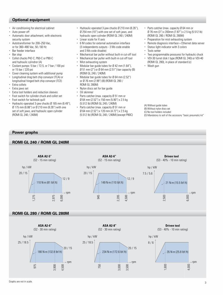
ASA A2-5”(S2 - 15 min rating)
Driven tool(S3 - 40% - 10 min rating)
110 N.m (81 lbf.ft)
hp / kW
20 / 15
1,27
5
2,97
5
6,00
0
12 / 9
rpm
ASA A2-6”(S2 - 15 min rating)
149 N.m (110 lbf.ft)
hp / kW
20 / 15
945
2,20
5
4,50
0
12 / 9
rpm
hp / kW
7.5 / 5.6
2,50
0
6,00
0
rpm
21 N.m (15.5 lbf.ft)
Driven tool(S3 - 40% - 10 min rating)
ASA A2-6”(S2 - 30 min rating)
180 N.m (132.8 lbf.ft)
hp / kW
25 / 18.5
975
3,90
0
4,50
0
20 / 15
rpm
ASA A2-8”(S2 - 30 min rating)
234 N.m (172.6 lbf.ft)
hp / kW
25 / 18.5
750
3,00
0
3,50
0
20 / 15
rpm
hp / kW
8 / 6
1,60
0
4,00
0
rpm
35 N.m (25.8 lbf.ft)
optional equipment
Power graphs
Romi GL 240 / Romi GL 240m
Romi GL 280 / Romi GL 280m

4
Turning
Turning Boring
Boring with offset facing
ASA A2 - 5” ASA A2 - 6” Chuck BH-M 165 Chuck BB-M 175 Chuck BH-M 210 Chuck BB-M 210A mm (in) Ø 165 (6.50) Ø 175 (6.89) Ø 210 (8.27) Ø 210 (8.27)B mm (in) 94 (3.70) 99 (3.90) 104 (4.09) 104 (4.09)C mm (in) 134 (5.27) 139 (5.47) 148 (5.83) 148 (5.83)
Drawings are not in scale.
X- =
184
(7.2
4)
150
(5.9
)
Z - = 395 (15.6) 105(4.1)
185
(7.2
8)
505 (20)
Head
stoc
k fa
ce
20 x 20 (0.79 x 0.79)
BC
Ø A
180
(7.1
)
X - =
184
(7.
24)
180
(7.1
)
Z - = 395 (15.6)
535 (21.1)
75(3)
Head
stoc
k fa
ce
Ø 32(1.26)C
B
Ø A
65(2.6)
180
(7.1
)X - =
184
(7.2
4)
130
(5.1
2)
Z- = 395 (15.6)93
(3.7)
25 (0.9
8)
25 (0.9
8)
47(1.85)
535 (21.1)
Head
stoc
k fa
ce
20 x 20(0.79 x 0.79)
Ø A
C
B
Boring
X - =
184
(7.2
4)
150
(5.9
)
Z - = 395 (15.6)
110(4.33)
185
(7.2
8)
505 (20)
Head
stoc
k fa
ce
Ø 32(1.26)
B C
Ø A
X -
= 18
4 (7
.24)
126
(4.9
6)
Z - = 395 (15.6) 88
(3.46)
185
(7.2
8)
505 (20)
Head
stoc
k fa
ce
20 x 20(0.79 x 0.79)
BC
Ø A
facing
180
(7.1)
X - =
184
(7.
24)
150
(5.9
)
Z - = 395 (15.6)55
(2.2)
30 (1.18
)
535 (21.1)
85(3.35)
Head
stoc
k fa
ce
Ø 32(1.26)
C
B
Ø A 18
0 (7
.1)X
- = 1
84 (7
.24)
138
(5.4
3)
Z - = 395 (15.6)55(2.17)
42 (1.6
5)
25 (0.98)
535 (21.1)
60 (2.36)
Head
stoc
k fa
ce
20 x 20(0.79 x 0.79)
C
B
Ø A
Work area layout for T type turret - dimensions in mm (in)
Work area layout for T or m type turret with VDi-30 tool disk - dimensions in mm (in)
Romi GL 240
Romi GL 240 / Romi GL 240m

5
Machining with radial driven tool Machining with axial driven tool
ASA A2 - 5” ASA A2 - 6” Chuck BH-M 165 Chuck BB-M 175 Chuck BH-M 210 Chuck BB-M 210A mm (in) Ø 165 (6.50) Ø 175 (6.89) Ø 210 (8.27) Ø 210 (8.27)B mm (in) 94 (3.70) 99 (3.90) 104 (4.09) 104 (4.09)C mm (in) 134 (5.27) 139 (5.47) 148 (5.83) 148 (5.83)
Romi tool disk VDI-30 tool disk (optional), for T and M type turrets
Ø 260 max.(10.24)
Ø 470 (18.5) max.with no interference
with protections
Spindlecenter line
Ø 276(10.9)
Ø 238(9.37)
184 (7.24)
50(1.97)
Ø 153(6.0)
45(1.8)
180(7.1)
4(0.16)
Offse
t 30 (
1.18)
34 (1.34)
X travel += 4 (0.16)
X travel -= 184 (7.24)
30(1.18)
* ER-
25Ø
1 ~ 16
(0.04
~ 0.6
3)
25(0.98)
Ø 32(1.26)
55 (2.2)Max.
ER-25Ø 1 ~ 16
(0.04~0.63)
X travel -= 184 (7.24)
Ø 270(10.63)
X- = 184 (7.24)
315(12.4)
Ø 32(1.26)
Drawings are not in scale.
180
(7.1
)X - =
184
(7.
24)
135
(5.3
1)
Z - = 395 (15.6)64(2.52)
45 (1.7
7)
535 (21.1)
76(3)
Head
stoc
k fa
ce
Ø 1~16(0.04~0.63)
C
B
Ø A 18
0 (7
.1)
X - =
184
(7.2
4)
180
(7.1
)
Z - = 395 (15.6)40(1.57)
535 (21.1)
100(3.94)
Head
stoc
k fa
ce
Ø 1 ~ 16(0.04~0.63)
C
B
Ø A
315 (12.4)
X travel -= 184 (7.24)
X travel += 4 (0.16)
Ø 252 (9.9)
34(1.34)
32(1.26)
150 (5.9)
Spindlecenter line
Ø 470 (18.5) max.with no interference
with protections
Ø 300 max.(11.8)
X- = 184 (7.24)
Work area layout for m type turret with VDi-30 tool disk standard - dimensions in mm (in)
Tool holder disk - dimensions in mm (in)
Romi GL 240 / Romi GL 240m

6 Drawings are not in scale.
Turning Boring
Turning Boring (*)
ASA A2 - 6” ASA A2 - 8” Chuck BH-M 210 Chuck BB-M 210 Chuck BH-M 250 Chuck BB-M 250A mm (in) Ø 210 (8.27) Ø 210 (8.27) Ø 254 (10) Ø 254 (10)B mm (in) 104 (4.09) 104 (4.09) 119 (4.68) 119 (4.68)C mm (in) 148 (5.83) 148 (5.83) 168 (6.61) 168 (6.61)
Z - = 535 (21.1)
X - =
208
(8.2
)
108(4.25)
135
(5.3
)
200
(0.7
9)
174
(6.8
5)
80 (3.15) 7 (0.3)190 (7.5)
445 (17.5)
175
(6.8
9)
650 (25.6)
199
(0.7
5)
Head
stoc
k fa
ce
25 x 25(0.98 x 0.98)
25 (0
.98)
Ø A
BC
Z - = 535 (21.1)
X - =
208
(8.1
9)
90(3.54)
110
(4.3
3)
28 (1
.1)
190
(7.4
8)17
1 (6
.73)
125
(4.9
2)
50 (1.97)25 (0.98)
90 (3.54)210 (8.27)
650 (25.6)
199
(7.8
3)
Head
stoc
k fa
ce Ø 40 max.(1.57)
BC
Ø A
Z - = 535 (21.1)
55 (2.17)
X - =
208
(8.1
9)
185
(7.2
8)13
0 (5
.12)
100
(3.9
4)
135 (5.31)195 (7.68)
139
(5.4
7)
77(3.0)
666 (26.2)
194
(7.6
4)
54(2.13)
55 (2
.17)
25 (0
.98)
Head
stoc
k fa
ce
25 x 25 (0.98 x 0.98)
C
B
Ø A
Z - = 535 (21)
90 (3.54)55 (2.17)
X - =
208
(8.1
9)
130
(5.1
2)10
0 (3
.94)
135 (5.31)195 (7.68)
194
(7.6
4)
41 (1.61)
666 (26.2)
194
(7.64
)
Head
stoc
k fa
ce Ø 40 (1.57) max.
CB
Ø A
Boring with offset (*)
X - =
208
(8.1
9)
195
(7.6
8)13
0 (5
.12)
100
(3.9
4)25
(0.9
8)
169
(6.6
5)
666 (26.2)
Head
stoc
k fa
ce Ø 40 (1.57) max.
C
B
Ø A
90 (3.54)55 (2.17)
135 (5.31)195 (7.68)
Z - = 535 (21)
194
(7.64
)
41 (1.61)
facing
X - =
208
(8.1
9)
185
(7.2
8)13
0 (5
.12)
100
(3.9
4)
53 (2
.09)
141
(5.5
5)
33 (1.3)
666 (26.2)
194
(7.6
4)
98 (3.86)
Head
stoc
k fa
ce
25 x 25(0.98 x 0.98)
C
B
Ø A
55 (2.17)135 (5.31)
195 (7.68)Z - = 535 (21)
Z - = 535 (21.1)
X - =
208
(8.1
9)
90(3.54)
54 (2
.13)
190
(7.4
8)14
5 (5
.7)
50 (1.97)85 (3.35)
200 (7.9)
135
(5.3
)
120
(4.7
2)
650 (25.6)
199
(7.8
3)
Head
stoc
k fa
ce
25 x 25(0.98 x 0.98)
BC
Ø A
25 (0.98)
facing
(*) Tailstock without live center
Romi GL 280
Work area layout for T type turret - dimensions in mm (in)
Romi GL 280 / Romi GL 280m
Work area layout for T or m type turret with VDi-40 tool disk standard - dimensions in mm (in)

7Drawings are not in scale.
Machining with radial driven tool - eR-32
Machining with radial driven tool - eR-20
Machining with axial driven tool (*) - eR-32
Machining with axial driven tool - eR-20
ASA A2 - 6” ASA A2 - 8” Chuck BH-M 210 Chuck BB-M 210 Chuck BH-M 250 Chuck BB-M 250A mm (in) Ø 210 (8.27) Ø 210 (8.27) Ø 254 (10) Ø 254 (10)B mm (in) 104 (4.09) 104 (4.09) 119 (4.68) 119 (4.68)C mm (in) 148 (5.83) 148 (5.83) 168 (6.61) 168 (6.61)
Romi tool diskVDI-40 tool disk (optional), for T and M type turrets
Ø 280 max.(11.02)
Ø 588 (23.15)with no interference
with protections
Ø 183(7.2)
Spindlecenter line
208 (8.19)Ø 300 (11.81)
X travel+ = 4 (0.16)
Ø 40(1.57)
Ø 284 (11.18)
38 (1.5)
13 (0.51)
X travel- = 208 (8.19)
25 (0.98)
ER-3
2Ø
2 - Ø
20(0.
08~0
.79)
80 (3.15)max.
195 (7.68)
55(2.17)
X travel- = 208 (8.19)
X- = 208 (8.19)
Ø 40(1.57)
25 (0.98)
44 (1.73)
Offse
t 25
ER-32Ø 2 - Ø 20(0.08~0.79)
365 (14.37)
Ø 340(13.39)
Z - = 535 (21.1)
55 (2.17)
X - =
208
(8.1
9)
190
(7.4
8)13
0 (5
.12)
100
(3.9
4)
44 (1
.73)
135 (5.31)195 (7.68)
150
(5.9
)
41 (1.61)
665 (26.2)
194
(7.6
4)
90 (3.54)
Head
stoc
k fa
ce
Ø 2~Ø 20(0.08~0.79)
C
B
Ø A
Z - = 535 (21.1)
55 (2.17)
X - =
208
(8.1
9)
130
(5.1
2)
135 (5.31)195 (7.68)
194
(7.6
4)
4 (0.16)
666 (26.2)
194
(7.64
)
127 (5)
Head
stoc
k fa
ce
Ø 2~Ø 20(0.08~0.79)
C
B
Ø A
Ø 340 max.(13.39)
365 (14.37)
X travel- = 208 (8.19)
X travel+ = 4 (0.16)
170 (6.69)
39(1.54)
Ø 588 (23.1) max.with no interference
with protections
X - = 208 (8.19)
36 (1.42)
Ø 292 (11.5)
Spindlecenter line
(*) Tailstock without live center.
Z - = 535 (21.1)
55 (2.17)
X - =
208
(8.1
9)
195
(7.6
8)13
0 (5
.12)
100
(3.9
4)18
(0.7
1)
135 (5.31)195 (7.68)
176
(6.9
3)35 (1.38)
666 (26.2)
194
(7.6
4)
96 (3.78)
Head
stoc
k fa
ce
Ø 2~Ø 20(0.08~0.79)C
BØ
A
Z - = 535 (21.1)
55 (2.17)
X - =
208
(8.1
9)
190
(7.4
8)13
0 (5
.12)
100
(3.9
4)
53 (2
.09)
135 (5.31)195 (7.68)
141
(5.5
5)
56 (2.2)
666 (26.2)19
4 (7
.64)
75(2.95)
Head
stoc
k fa
ce
Ø 2~Ø 20(0.08~0.79)
C
B
Ø A
Work area layout for m type turret with VDi-40 tool disk - dimensions in mm (in)
Tool holder disk - dimensions in mm (in)
Romi GL 280 / Romi GL 280m

8
(*) Quantity supplied with the machine. One set in millimeters or one set in inches, according to the market.
Drawings are not in scale.
Tool holders Romi GL 240 Romi GL 280
Section Code Qt (*) Section Code Qt (*)
facing tool holder mm (in) 20 x 20 (3/4 x 3/4) T67710 (T70286) 1 (1) 25 x 25 (1 x 1) T67753 (T70308) 1 (1)
Boring tool holder mm (in) Ø 32 (Ø 1 1/4) T67651 (T70284) 4 (4) Ø 40 (Ø 1 1/2) T67762 (T70303) 4 (4)
Reduction sleeves
mm (in) Ø 8 (Ø 5/16 x Ø 1 1/4) T73331 (T73417) 1 (1) Ø 10 (Ø 3/8 x Ø 1 1/2) T73389 (T73431) 1 (1)
mm (in) Ø 10 (Ø 3/8 x Ø 1 1/4) T73335 (T73420) 1 (1) Ø 12 (Ø 1/2 x Ø 1 1/2) T73392 (T73433) 1 (1)
mm (in) Ø 12 (Ø 1/2 x Ø 1 1/4) T73339 (T73422) 1 (1) Ø 16 (Ø 5/8 x Ø 1 1/2) T73394 (T73435) 1 (1)
mm (in) Ø 16 (Ø 5/8 x Ø 1 1/4) T73341 (T73424) 1 (1) Ø 20 (Ø 3/4 x Ø 1 1/2) T73396 (T73437) 1 (1)
mm (in) Ø 20 (Ø 3/4 x Ø 1 1/4) T73344 (T73426) 1 (1) Ø 25 (Ø 1 x Ø 1 1/2) T73398 (T73439) 1 (1)
mm (in) Ø 25 (Ø 1 x Ø 1 1/4) T73349 (T73429) 1 (1) Ø 32 (Ø 1 1/4 x Ø 1 1/2) T73400 (T73441) 1 (1)
Boring tool holder
facing tool holder
Reduction sleeves
Tool holders and reduction sleeves for T type turret - Romi disk

9Drawings are not in scale.
Section Code Qt (*) Section Code Qt (*)Turning tool holder (left tool) mm (in) 20 x 20 (3/4 x 3/4) s72739 (T45279) 4 (4) 25 x 25 (1 x 1) R99187 (s51729) 4 (4)Turning tool holder overhead (right tool) mm (in) 20 x 20 (3/4 x 3/4) T45316 (T45280) 3 (3) 25 x 25 (1 x 1) s39389 (s51730) 3 (3)facing tool holder (right tool) mm (in) 20 x 20 (3/4 x 3/4) R99489 (T45284) 1 (1) 25 x 25 (1 x 1) R99491 (s51731) 1 (1)facing tool holder overhead (left tool) mm (in) 20 x 20 (3/4 x 3/4) T45314 (T45313) - 25 x 25 (1 x 1) T48196 (T48197) -
mm (in) Ø 20 (Ø 3/4) T45403 (T45406) - Ø 20 (Ø 3/4) T45411 (T45419) - Boring bar holder (internal cooling) mm (in) Ø 25 (Ø 1) T45404 (T45408) - Ø 25 (Ø 1) T43215 (T45420) -
mm (in) Ø 32 (Ø 1 3/4) T45405 (T45409) - Ø 32 (Ø 1 1/4) T43216 (T45421) - mm (in) - - - Ø 40 (Ø 1 1/2) T45417 (T45422) - Boring bar holder (external cooling) mm (in) Ø 32 (Ø 1 1/4) R99497 (T45282) 3 (3) Ø 40 (Ø 1 1/2) R99498 (s51723) 3 (3)Boring bar holder offset mm (in) Ø 32 (Ø 1 1/4) T41433 (-) 1 (1) Ø 40 (Ø 1 1/2) T41391 (T41394) 1 (1)Reduction sleeves mm (in) Ø 10 (Ø 3/8) T45253 (T45259) 1 (1) Ø 10 (Ø 3/8) s51738 (s51732) 1 (1)
mm (in) Ø 12 (Ø 1/2) T45254 (T45260) 1 (1) Ø 12 (Ø 1/2) s51739 (s51733) 1 (1) mm (in) Ø 16 (Ø 5/8) T45255 (T45258) 1 (1) Ø 16 (Ø 5/8) s51740 (s51734) 1 (1) mm (in) Ø 20 (Ø 3/4) T45256 (T45262) 2 (2) Ø 20 (Ø 3/4) s51741 (s51735) 1 (2) mm (in) Ø 25 (Ø 1) T45257 (T45263) 1 (1) Ø 25 (Ø1) s51742 (s51736) 2 (1) mm (in) - - - Ø 32 (Ø 1 1/4) s51743 (s51737) 1 (-)
axial driven mm (in) - - - eR-20 T62813 -mm (in) eR-25 T59847 - eR-32 T59850 -
Radial driven mm (in) - - - eR-20 T64011 -mm (in) eR-25 T59845 - eR-32 T59852 -
Tool holders Romi GL 240m Romi GL 280m
(*) Quantity supplied with the machine. One set in millimeters or one set in inches, according to the market.
Turning tool holder
Turning tool holder inverse
Boring bar holder
Boring bar holder with offset
axial driven tool holder
Radial driven tool holder
Reduction sleeve
Reduction sleeve
Tool holders and reduction sleeves for m type turret - VDI disk
10
B
A
F
D EElectrical cabinet
door openningspace required
G
C
Space for coolant tank+ chip conveyor removal
H
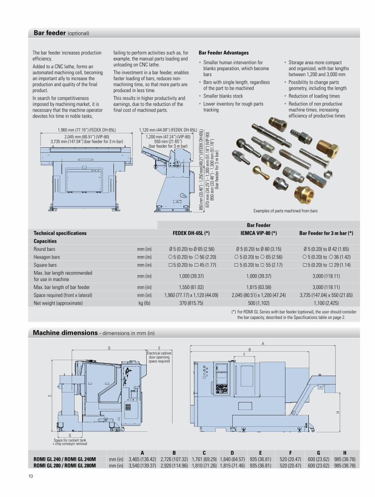
A B C D E F G HRoMi GL 240 / RoMi GL 240M mm (in) 3,465 (136.42) 2,726 (107.32) 1,761 (69.29) 1,640 (64.57) 935 (36.81) 520 (20.47) 600 (23.62) 985 (38.78)RoMi GL 280 / RoMi GL 280M mm (in) 3,540 (139.37) 2,920 (114.96) 1,810 (71.26) 1,815 (71.46) 935 (36.81) 520 (20.47) 600 (23.62) 985 (38.78)
The bar feeder increases production efficiency.added to a CnC lathe, forms an automated machining cell, becoming an important ally to increase the production and quality of the final product.In search for competitiveness imposed by machining market, it is necessary that the machine operator devotes his time in noble tasks,
Bar Feeder Advantages
• smaller human intervention for blanks preparation, which become bars
• Bars with single length, regardless of the part to be machined
• smaller blanks stock • lower inventory for rough parts
tracking
failing to perform activities such as, for example, the manual parts loading and unloading on CnC lathe.The investment in a bar feeder, enables faster loading of bars, reduces non-machining time, so that more parts are produced in less time.This results in higher productivity and earnings, due to the reduction of the final cost of machined parts.
• storage area more compact and organized, with bar lengths between 1,200 and 3,000 mm
• possibility to change parts geometry, including the length
• Reduction of loading times• Reduction of non productive
machine times, increasing efficiency of productive times
examples of parts machined from bars
(*) for ROMI gl series with bar feeder (optional), the user should consider the bar capacity, described in the specifications table on page 2.
1,960 mm (77.16”) (FEDEK DH-65L)2,045 mm (80.51”) (VIP-80)
3,735 mm (147.04”) (bar feeder for 3 m bar)
1,120 mm (44.09”) (FEDEK DH-65L)1,200 mm (47.24”) (VIP-80)
550 mm (21.65”)(bar feeder for 3 m bar)
850 m
m (3
3.46”
) - 1,
250 m
m (4
9.21”
) (FED
EK D
H-65
L)87
0 m
m (3
4.25
”) -
1,30
0 m
m (5
1.18
”) (V
IP-8
0)85
0 m
m (3
3.46
”) -
1,30
0 m
m (5
1.18
”)(b
ar fe
eder
for 3
m b
ar)
Bar FeederTechnical specifications FEDEK DH-65L (*) iEMCA ViP-80 (*) Bar Feeder for 3 m bar (*)CapacitiesRound bars mm (in) Ø 5 (0.20) to Ø 65 (2.56) Ø 5 (0.20) to Ø 80 (3.15) Ø 5 (0.20) to Ø 42 (1.65)hexagon bars mm (in) 5 (0.20) to 56 (2.20) 5 (0.20) to 65 (2.56) 5 (0.20) to 36 (1.42)square bars mm (in) 5 (0.20) to 45 (1.77) 5 (0.20) to 55 (2.17) 5 (0.20) to 29 (1.14)Max. bar length recommended for use in machine mm (in) 1,000 (39.37) 1,000 (39.37) 3,000 (118.11)
Max. bar length of bar feeder mm (in) 1,550 (61.02) 1,615 (63.58) 3,000 (118.11)space required (front x lateral) mm (in) 1,960 (77.17) x 1,120 (44.09) 2,045 (80.51) x 1,200 (47.24) 3,735 (147.04) x 550 (21.65)net weight (approximate) kg (lb) 370 (815.75) 500 (1,102) 1,100 (2,425)
Bar feeder (optional)
machine dimensions - dimensions in mm (in)

11
Resources and CNC Performance• Minimum Increment positioning
0.001mm or inches and 0.001° • simultaneous control
of up to 4 axes • stroke limit Check Before Move • linear Interpolation • Circular Interpolation • helical Interpolation • protection Key • pCMCIa Interface • puncher Interface (Rs-232C) • ethernet Interface • programmed Codes (T, s, M, f) • parts number display • Clock
• pitch error • Bell-shaped • acceleration/deceleration after
interpolation for rapid traverse • error Detection • power Mate Manager • Machine lock • software limit • Inter-locking • Backlash Compensation • Torque limit skip • Idioms: portuguese, english,
german, french, Italian,spanishProgramming Resources• Thread Cutting • Variable lead Thread Cutting • Threading Retract • programmable Return to Reference
position of machine (g28, g30 e g53) Feedrate Functions• feed in mm/min or inches/min (g94)
[feed per Minute] • feed per Rotation • Dwell (g04)Graphic Functions• graphic DisplayCoordinate Systems• local Coordinate system setting • Machine Coordinate system
selection (53) • Workpiece Coordinate system
(g54~g59) • Workpiece Coordinate preset
(g92, g92.1) • Tool geometry and Wear
CompensationCoordinate Values and Dimensions • Coordinate system shift • programmable in absolute Mode
(g90) and Incremental Mode (g91) • Inch/Metric Conversion (g20, g21) • Coordinate system Rotating • Transfer Zero point • programmable Mirror Image • programmable in radius or diameter • programmable Data Input
Spindle Functions • C axis Control (M19 + g0 C __) -
just for ROMI gl 240M/280M • Constant surface speed Control • spindle speed function • spindle Orientation (M19) • Monitoring of current spindle speed • live tool Oriented stop -
just for ROMI gl 240M/280MApplied Tool Function• Tool Radius Compensation • Input RelativeTool Corrector • Direct Measurement of Tool Corrector• Tool life Management • Tool Interactive screen • Tool preset Interactive screenMacro• Macro B • addition of Custom Macro
Commom Variable • Macro executor • 4 Mbytes of memory for application
in “Macro executor” • ladderSimplification Program Functions• finishing Cycle • stock Removal in Turning • stock Removal in facing • pattern Repeating • end face peck Drilling Cycle • Multiple Threading Cycle • Multiple Repetitive Cycle Type II • Direct Drawing Dimension • Drilling • Rigid Tapping • Cylindrical Interpolation -
for ROMI gl 240M/280M • polar Coordenate Interpolation -
just for ROMI gl 240M/280M • poligonal Machining -
for ROMI gl 240M/280M • Canned Cycle for Turning • Threading Cycles • facing CyclesProgramming Format• programming format Command IsO
fanuc-10/11 • Manual guide i • parameter Configuration
Execution operations• number / program Research • Comments • sub-program Call • MDI Operation • Cycle start • single Block • stop program execution • Optional stop • Omission Block (“/”) • program Restart • DnC function • program Test function • Dry Run function • Machine home • Jump high speed skip • spindle Controller speed Key • Return and Manual Intervention • family a, B and C (g Codes) • search Block “n” program • extend part program editing • Background editing • Memory program number = 400 • part program storage = 512
Kbytes (1,280m) • Manual handle feed • JOg feed • Key speed Control of spindleMaintenance Functions• Course limits • security area • emergency stop • external Message ladder • alarm history • Operating history • Maintenance • analysis of behavior system of
servo Mechanism • help On-line • Diagnosis screen • Maintenance screen
CNC Features
CNC Fanuc 0i - TD

Ds R
OMI g
l 24
0 - g
l 24
0M -
gl 2
80 -
gl 2
80M
/ In
/ aO
/ 09
2015
- Ill
ustra
tive
phot
os -
spec
ifica
tions
are
sub
ject
to c
hang
e w
ithou
t prio
r not
ice
- ple
ase
recy
cle.
CE safety regulation compliance available only for the European Community or under request.
WoRLDWiDE PRESENCE
W W W . R O M I . C O M
indústrias Romi SA Rod. sp 304, Km 141,5 santa Bárbara d’Oeste sp 13453 900 Brazil phone +55 (19) 3455 9800 fax +55 (19) 3455 1030 [email protected]
RoMi Europa GmbH Wasserweg 19 D 64521 gross gerau germany phone +49 (6152) 8055 0 fax +49 (6152) 8055 50 [email protected]
RoMi France SAS parc de genève, 240 Rue ferdinand perrier 69800 sT priest phone +33 4 37 25 60 70 fax +33 4 37 25 60 71 [email protected]
Burkhardt+Weber Fertigungssysteme GmbH Burkhardt+Weber-strasse 57 72760 Reutlingen, germany phone +49 7121 315-0 fax +49 7121 315-104 [email protected] www.burkhardt-weber.de
RoMi Machine Tools, Ltd 1845 airport exchange Blvd erlanger KY - 41018 usa phone +1 (859) 647 7566 fax +1 (859) 647 9122 [email protected]
RoMi Machines UK Limited leigh Road swift Valley Industrial estate Rugby CV21 1Ds phone +44 1788 544221 fax +44 1788 542195 [email protected]
RoMi Máquinas España Calle Comadrán, 15 pol. Ind. Can salvatela C.p. 08210 - Barberà del Vallès phone +34 93 719 4926 fax +34 93 718 7932 [email protected]
RoMi in Mexico Moliere 13, piso 10-B Col. Chapultepec polanco, C.p. 11560 [email protected]
RoMi italia Srl Via Morigi, 33 - 29020 gossolengo, piacenza - Italy phone +39 349 590 0474 [email protected]
ROMI - BRaZIl
ROMI - uK
ROMI - geRManYROMI - ITalY
ROMI - fRanCe
ROMI - spaIn
ROMI - MeXICO
ROMI - usa
Germany - B+WitalyBrazil GermanyUnited States SpainFranceEngland