Embed Size (px)
Citation preview

ROLE OF COHERENCY STRAIN IN MICROSTRUCTURAL DEVELOPMENT
Jong K. Lee Department of Metallurgical and Materials Engineering
Michigan Technological University Houghton, MI 4993 1, USA
Abstract
With a purely dilatational misfit strain, an elastically-soft, coherent precipitate imbedded in an infinite matrix tends to have a plate-like equilibrium morphology, whereas a hard particle tends to take on a round shape of high symmetry. Shape evolution proceeds through dynamic activities of coherency-induced interfacial waves. These interfacial waves seem to be responsible for the protrusions often observed along elastically hard directions in coherent particles of nickel-based superalloys. Soft particles with a positive misfit strain become plates perpendicular to an applied tensile stress, while hard particles elongate along the stress direction. If the elastic interaction between the applied stress and the coherency strain is strong enough, soft precipitates often split into smaller particles and then follow coarsening. If the applied stress increases further, coherent particles tend to dissolve into the matrix - in agreement with the theory of coherent phase equilibria. As expected, a coher- ent particle with a positive misfit strain migrates to the tension region of an edge dislocation, whereas a particle with a negative strain diffuses to the region of compression. Morphological change is, however, caused by the dislocation as the particle tries to capi- talize on the dislocation stress field. The results are analyzed by means of a discrete atom method (DAM), which is predicated upon Hookean atomic interactions and Monte Carlo diffusion under the condition of a plane strain, a pureiy dilatational misfit strain, and no dislocation climbing.
Introduction
The microstructural development of nickel-based superalloys or other age-hardenable alloys has been a subject of great interest, as it is closely tied to the performance during application. For unstressed two-phase alloy systems, the equilibrium shape of a precipitate is established solely by the interfacial free energy and its dependence on crystallographic orientation. On the other hand, the equilibrium morphology of second-phase, coherent precipitates is dictated by both the interfacial free energy and the elastic strain energy. Consequently, there has been a need for a computational technique, through which one can analyze the elastic state associ- ated with arbitrarily-shaped precipitates whose elastic constants are different from those of the matrix phase.
Eshelby (1) was the pioneer in the field of coherency strain who devised the seminal equivalency method and thus brought much understanding to the coherency strain problem; however, the method is limited to a single ellipsoidal precipitate (2-4). Since his
work, several numerical techniques have been developed, but most involve either computations of an elastically homogeneous state, or approximate solutions for integro-differential equations when faced with an inhomogeneous system (5-13). In an effort to develop a tool to study general shape evolution of a coherent pre- cipitate, a Discrete Atom method (DAM) was recently developed on the basis of a statistical approach (14,15). The method has been applied to a number of coherency strain problems (16- 18), demon- strating that an elastically inhomogeneous, multi-particle system can be readily analyzed. In this work, the DAM is reviewed to examine morphological evolution of second-phase, coherent part- cles with a purely dilatational transformation strain.
Discrete Atom Method
A two-dimensional triangular lattice with Hookean nearest neigh- bor interaction is elastically isotropic (19). If the atomic bond energy is expressed in the form of k(r - a)2/2, both Lame elastic constants, h (= Ctz) and p (= C44), are equal to 0.433k, where k is the spring constant, r is the interatomic distance, and a is the lattice parameter of the lattice. A coherent precipitate is designated with a different spring constant and lattice parameter, k* and a* = a(1 + E), where E is the dilatational misfit strain. Directional, instead of uniform, spring constants make the crystal elastically anisotropic. Cubic systems with Zener’s anisotropy ratio, A = 2C&(Clr - Cl,) = 2.33 are studied to mimic nickel-based superalloys. Since the major concern is coherency effects, an isotropic interface energy is assumed. An interface atom is defined as the precipitate atom hav- ing unlike nearest neighbor bonds, and has a specific interfacial energy depending on the number of unlike bonds. Morphological evolution is then examined through a Monte Carlo process, which, by exchanging precipitate and matrix atoms, generates a Boltz- mann-weighted chain of the configurations of a given system. The details of the DAM was described elsewhere (14,15).
All the computations are performed under the conditions of a con- stant number of precipitate atoms, a pure dilatational misfit, and a plane strain. The ‘diffusion’ temperature is kept low enough so that surface roughening is negligible and yet atoms have sufficient mobility for shape change. Here diffusion means a process of atomic site exchange, which may imply vacancy mechanism, but no real vacancies are introduced into the system. Thus the work is intended to mimic low temperature phenomena in which the pres- ence of point defects is insignificant to relax the coherency strain itself. With k = 1.38x10~%a2 and isotropic interfacial energy, y0 = 2.5x10⁻²tJ/a, a typical temperature of 50K is used for a system in
Superalloys 1996 Edited by R. D. Kissinger, D. J. Deye, D. L. Anton,
A. D. C&l, M. V. Nathal, T. M. Pollock, and D. A. Woodford The Minerals, Metals & Materials Society, 1996
211

which the melting point of the matrix phase is about 10OOK.
The results in the first four parts deal with a dislocation-free sys- tem. In the last part, effects of edge dislocations are examined. Dis- location gliding is permitted, but no dislocation climbing is allowed as it requires a substantial amount of point defects which may relax coherency strain. The introduction of edge dislocations is accomplished with a truncated Hookean potential (19). The potential is made of three interaction zones: k[(r - a)2/2 - w2] if r 5 a+w,-k(r-a-2w)2/2ifa+w<r<a+2w,andOforr>a+2w, where w/a is equal to 0.15 for the interaction with first nearest neighbors and 0.10 for second nearest neighbors. In the text, if elastic stiffness is described in terms of shear modulus, p, it indi- cates an elastically isotropic system, whereas if the stiffness is measured in terms of Cijkl, an anisotropic system is meant. Both isotropic and anisotropic elasticity results are discussed to under- stand intriguing coherency strain effects.
Results and Discussion
Shave Bifurcation
If one carefully examines the shape evolution of typical N&Al pre- cipitates in nickel-based superalloys (20), it is easy to recognize a series of shape bifurcations beginning from a spherical shape (radial symmetry) to a cuboidal shape (four-fold symmetry), then to a plate-like shape (two-fold symmetry), as their size increases. This is a straight manifestation for the competition between the y r’ interfacial energy and the elastic strain energy, as was shown elegantly by Johnson and Cahn (21). Let us examine a shape bifur- cation behavior as displayed through the DAM. In Fig. 1, soft, iso- tropic precipitates with p* = @2, E = 0.05, and y = ye undergo shape evolution at T = 50K. Size, R, along the horizontal axis indi- cates the particle radius in units of a, while p on the vertical axis marks the aspect ratio with p = 1 indicating a circle. J-C denotes the bifurcation point predicted from the Johnson-Cahn theory. For each particle size, a circle is the initial shape, and snap-shot mor-
Size, R ---) I 17 8 9 10 11 12 13 14
f
Figure 1: A shape bifurcation diagram for soft, isotropic particles with lt* = p/2, E = 0.05, and y = ye. Size, R, along the horizontal axis indicates the particle radius in units of a, while Shape, p, on the vertical axis marks the aspect ratio with l3 = 1 indicating a cir- cle. J-C denotes the bifurcation point predicted from the Johnson- Cahn theory. For each particle size, a circle is the initial shape, and snapshot morphologies during the evolution are exhibited down- ward.
phologies during the evolution are exhibited downward. With the DAM, the bifurcation from a circle to an ellipse-like shape occurs at R G 9a, which is close to the Johnson-G&n analytical value, 7~. Note also that the particles with R > 14a experience transient state(s) from a circular to a polygon-like shape, before reaching a plate-like equilibrium shape.
In Fig. 2, fractional changes in energy versus Monte Carlo steps (MCS) are plotted fort the precipitate with R = 14a of Fig. 1. The broken curve at the top represents change in the interfacial energy, the solid curve at the middle is for the sum of the interfacial and elastic strain energy, and the bottom, dotted curve is for the elastic stain energy. Two distinctive plateaus are clearly displayed on the top, interfacial energy curve: the first plateau between MCS = 5M (M for a million steps) and 20M stands for a triangle-like shape of a three-fold symmetry, while the second one from MCS = 28M and thereafter indicates a plate-like shape of a two-fold symmetry. At the final equilibrium, the interfacial energy shows an increase of 31%, the strain energy registers a decrease of 12%, and the total energy is reduced by 3%.
Figure 2: Fractional changes in energy versus Monte Carlo steps for a soft, isotropic precipitate with R = 14~ and E = 0.05. The top, broken curve represents change in the interfacial energy, the mid- dle, solid curve is for the sum of the interfacial and strain energy, and the bottom, dotted curve is for the elastic stain energy. Note two distinctive plateaus on the interfacial energy curve, indicating shape transitions from a radial to a three-fold, then to a two-fold symmetric shape.
The fact that all the soft particles with a pure dilatational misfit attain a plate-like equilibrium shape confirms the well-known Eshelby’s inclusion theory that the stress field within a thin plate is one-dimensional along its major axis, and consequently all the strain energy tends to be contained in the soft plate itself (2,3). Similarly, a separate DAM work upheld Crum’s theorem that for the homogeneous case (l.t* = p), the strain energy of a particle is independent of its shape (1). If the particle is stiffer than the matrix as in a case with l.t* = 2l.t., however, the strain energy is proven to drive the particle morphology toward a circle. Shape transition is found to begin with interfacial waves induced by the coherency strain, whose wavelengths depend on elastic constants, particle geometry, anisotropy, misfit strain, and diffusion temperature. The wave activities are more pronounced with large precipitates, an example of which is demonstrated in Fig. 3. Conditions similar to those of Fig. 1 are placed to a soft particle with R = 35~. A circular,
212
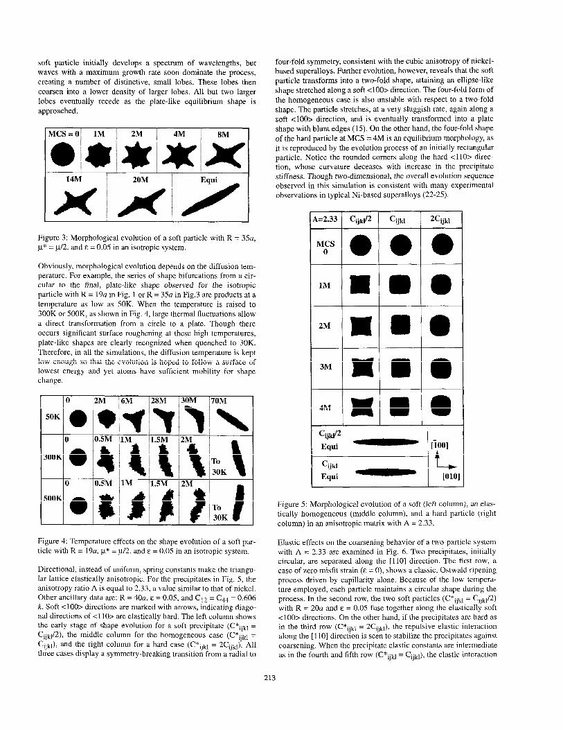
soft particle initially develops a spectrum of wavelengths, but waves with a maximum growth rate soon dominate the process, creating a number of distinctive, small lobes. These lobes then coarsen into a lower density of larger lobes. All but two larger lobes eventually recede as the plate-like equilibrium shape is approached.
Figure 3: Morphological evolution of a soft particle with R = 35a, CL* = cL/2, and E = 0.05 in an isotropic system.
Obviously, morphological evolution depends on the diffusion tem- perature. For example, the series of shape bifurcations from a cir- cular to the final, plate-like shape observed for the isotropic particle with R = 19~ in Fig. 1 or R = 35~ in Fig.3 are products at a temperature as low as 50K. When the temperature is raised to 300K or 500K, as shown in Fig. 4, large thermal fluctuations allow a direct transformation from a circle to a plate. Though there occurs significant surface roughening at these high temperatures, plate-like shapes are clearly recognized when quenched to 30K. Therefore, in all the simulations, the diffusion temperature is kept low enough so that the evolution is hoped to follow a surface of lowest energy and yet atoms have sufficient mobility for shape change.
I 10 i2M i6M i 28M I30M
10 j0SM j1M /l.SM ; 2M -
70M
\
l-0
30K \
Figure 4: Temperature effects on the shape evolution of a soft par- ticle with R = 19~2, I** = u/2, and E = 0.05 in an isotropic system.
Directional, instead of uniform, spring constants make the triangu- lar Iattice elastically anisotropic. For the precipitates in Fig. 5, the anisotropy ratio A is equal to 2.33, a value similar to that of nickel. Other ancillary data are: R = 40a, E = 0.05, and Cl2 = C44 = 0.606 k. Soft <loo> directions are marked with arrows, indicating diago- nal directions of <l lO> are elastically hard. The left column shows the early stage of shape evolution for a soft precipitate (C*ijkt = Cijk,/2), the middle column for the homogeneous case (C*,jkl = C+l), and the right column for a hard case (C*ijkl = 2Cukl). All three cases display a symmetry-breaking transition from a radial to
four-fold symmetry, consistent with the cubic anisotropy of nickel- based superalloys. Further evolution, however, reveals that the soft particle transforms into a two-fold shape, attaining an ellipse-like shape stretched along a soft <loo> direction. The four-fold form of the homogeneous case is also unstable with respect to a two-fold shape. The particle stretches, at a very sluggish rate, again along a soft <loo> direction, and is eventually transformed into a plate shape with blunt edges (15). On the other hand, the four-fold shape of the hard particle at MCS = 4M is an equilibrium morphology, as it is reproduced by the evolution process of an initially rectangular particle. Notice the rounded corners along the hard <llO> direc- tion, whose curvature deceases with increase in the precipitate stiffness. Though two-dimensional, the overall evolution sequence observed in this simulation is consistent with many experimental observations in typical Ni-based superalloys (22-25).
A ~~2.33 Cij& cijkl 2Cijkl
Mocs a * a
lM m 0 0
2M I D 0
3~ x l 0 4M x m 0 Cij&2
Equi - ii001
c- ljkl L Equi ww
Figure 5: Morphological evolution of a soft (left column), an elas- tically homogeneous (middle column), and a hard particle (right column) in an anisotropic matrix with A = 2.33.
Elastic effects on the coarsening behavior of a two-particle system with A = 2.33 are examined in Fig. 6. Two precipitates, initially circular, are separated along the [llO] direction. The first row, a case of zero misfit strain (E = 0), shows a classic, Ostwald ripening process driven by capillarity alone. Because of the low tempera- ture employed, each particle maintains a circular shape during the process. In the second row, the two soft particles (C*ijkl = CijklR) with R = 20~ and E = 0.05 fuse together along the elastically soft <loo> directions, On the other hand, if the precipitates are hard as in the third row (C*ijkl = 2Cijkl), the repulsive elastic interaction along the [l lo] direction is seen to stabilize the precipitates against coarsening. When the precipitate elastic constants are intermediate as in the fourth and fifth row (C*ijkl= Cijkl), the elastic interaction
213

also appears to stabilize the particles. But it is only transient: the particles migrate slowly along the [OlO] to lower the energy, and eventually coalesce to yield a plate-like equilibrium shape. Even with two-particle systems shown here, one can easily recognize that there occurs a significant shape change and realignment for soft particles, and to a lesser degree, for the homogeneous parti- cles. Continuous fusion and migration processes among the parti- cles are clearly seen to promote linear stringers along elastically favorable directions. On the other hand, hard particles display strong coherency-stabilizing effects.
L.5M
__. ._ ._..... ,.., 85M
Figure 6: Coarsening behavior of two precipitates in an anisotropic matrix with A = 2.33. The first row with zero misfit strain shows a classical, capillary-driven ripening process, whereas the second row displays fusing of two soft particles along elastically-soft directions. The third row shows a coherency-stabilized state for the hard particles. The homogeneous case of the fourth and fifth row portrays a stabilized state in the early stage, but an ensuing coales- cence forming a plate-like equilibrium shape.
Effects of Annlied Stress
To control microstructural development, external stresses are often applied to alloy systems. For example, Tien and Copley (26) showed that when a tensile stress was applied along the [OOl] direction, r plates in the Udimet 700 precipitated on the (001) plane. When the applied stress direction was reversed, the precipi- tates became rods parallel to the [OOl] direction. Miyazaki et al., however, refuted these results by showing that Ni3Al rods and plates aligned along the tensile [OOl] axis in Ni-15 at.% Al alloys (27). Equally contradicting morphological evolution is also reported for other alloy systems such as Al-Cu alloys (2829). Though unsettling and confusing, these experimental results are certainly calling for further understanding of the applied stress effects. Several theoretical investigations which treat the change in strain energy, with particle shape were reported (1,3,30-33). In this section, we examine the shapes predicted from the DAM under applied stresses.
The effect of a pure dilatational misfit strain should be similar to that of a hydrostatic pressure on an inhomogeneous particle with E = 0 imbedded in an infinite matrix. This is demonstrated in Fig. 7, where both soft (p* = p/2) and hard Q.t* = 2~) particles with R =
25a are placed under a hydrostatic pressure with a magnitude equal to 5% strain. The shape transition for the circular, soft particle starts with dynamics of interfacial waves induced by the inhomo- geneity. The waves of a maximum growth rate dominate the early evolution process, creating several large lobes. A coarsening pro- cess follows, leading the morphology to an elliptical equilibrium shape. Compared to the misfit strain case of Fig. 3, the lobe tips are quite sharp, indicating a high stress concentration. For the hard, rectangular particle, there are two driving forces to drive the shape toward a circle: the isotropic interfacial energy and the strain energy due to the inhomogeneity effect.
Figure 7: Morphological evolution of both soft (l.t* = cl/2) and hard (cl* = 211) isotropic particles with E = 0 under a hydrostatic pres- sure. Similar to the dilatational misfit strain case, the soft particle becomes a plate, while a hard particle attains a circular shape at equilibrium.
In Fig. 8, an isotropic, soft particle with R = 17a, E = 0.05, and p* = p/2 is placed under a uniaxial compressive stress with a magni- tude equal to 4% strain along the vertical direction. With a positive misfit strain, this soft particle has to align its major axis parallel, instead of perpendicular, to the applied stress axis. Being mis- placed, the particle must reorient itself. Instead of rotating on a high energy path, however, the precipitate undergoes splitting at first, then coalescence before reaching its equilibrium state. At the birth, the small platelets position themselves properly with the applied stress. During the follow-up coarsening, some smaller platelets sustain diffusional migration before their demise. If a pre- cipitate begins a shape transition from a highly non-equilibrium state, such an evolution of splitting-coalescence is found to be a common feature ( 15).
To illuminate the effects of an applied stress, a schematic shape stability diagram is constructed in Fig. 9, where the alignment of both soft (p* = c1/2, gray) and hard Q.L* = 2p., black) particles is shown under a uniaxial applied stress with a magnitude equal to
214

0.05M ^
O*lM w
0.2M q +
OSM
w
1M
w
2M t
3M 1
I 4M
5M
Equi
I
Figure 8: Morphological evolution of an isotropic, soft particle with R = 17a, E = 0.05, and p* = p/2 under a compressive applied stress along the vertical direction.
A +e- 'J
T* - eij + &* ‘J
0 0 -0 soft
Figure 9: Shape stability diagram of coherent precipitates under a uniaxially-applied tensile or compressive stress. T
9 e horizontal
axis indicates the sense of the misfit strain with + eij for a posi- tive misfit strain, while the vertical axis represents the sense of the applied stress with +,G for a tensile stress directed along the verti- cal axis. The applied stress magnitude is equivalent to 4% strain, and the stiffness is at the level of p* = p/2 for a soft (gray), and l.t* = 2~ for a hard (black) particle.
4% strain. The positive x-axis, + cc , indicates a positive misfit strain (5%), while a negative misfit (5%) is marked with -e7* . The positive ordinate, marked with +e!., stands for a tensili’stress, whereas a compressive stress is ind;Lated by -ct. Thus a hard par- ticle with a positive misfit strain aligns its major axis parallel to the tensile stress axis as indicated in the 1st quadrant. If the hard parti- cle has a negative misfit strain, however, its major axis becomes perpendicular to the stress axis (2nd quadrant). In the absence of applied stress, a hard particle commands a circular shape regard- less of the misfit strain sign, as shown along the abscissa.
What makes such a drastic difference in the alignment? Following Eshelby (l), we may write the energy of the system containing an
elliptical precipitate, @, as:
Here V and S are the area and perimeter of the elliptical precipi- tate, respectively, and y is the interfacial energy per unit length. The constrained strain, ei’, is the product of Eshelby’s Fsor and an equivalent stress-free tra-@rmation strain, S;jklc,, , and is related to the misfit strain, eij , m the form of:
The second equivalent stress-free transformation strain, e;F, arises due to the applied stress, c$ = Cijk,e$, and is obtained from the following relationship:
The first term in Eq. (1) is the self strain energy due to the misfit strain, e’, and the second term is the interaction energy between the app&d stress and the misfit strain. The third term indicates the inhomogeneity effect due to the applied stress, and the last repre- sents the capillary effect. As pictured in the first quadrant in the stability diagram of Fig. 9, let us consider the shape change of a hard precipitate with E = +0.05 and p* = 2~ from a circle to an ellipse-like under a tensile stress. Let the aspect ratio of an ellipse be p = b/a, where a and b are the semi-axes along the horizontal and vertical direction, respectively. For a hard particle with a pure dilatation (1,2), the self strain energy prefers a circular shape. The inhomogeneity term increases slightly with p, but the interaction energy decreases more rapidly with /3, and thus the sum of these elastic energy terms sets its minimum at fi > 1. If the applied stress is large enough, the decrease in the interaction term can offset more than the increase in the summed energy of self strain energy, inhomogeneity term, and interfacial energy, thus leading the part- cle shape to an ellipse-like with p > 1. If the particle is soft (p* = lU2), on the other hand, the interaction energy decreases with decrease in p. Thus for a soft particle, all the elastic energy terms favor a shape with p + 0. Obviously, if the decrease in the elastic energy terms makes up more than the increase in the interfacial energy, the particle achieves an ellipse-like shape (p < 1) perpen- dicular to the applied stress axis.
The interaction behavior between an applied stress and a coher- ency strain is intriguing and certainly complicated as it depends not only on the sense of the various strain terms but also on their magnitude. Put in a simplified picture, it could be argued that a hard, elliptical particle accommodates more of its misfit strain along the direction of the major axis, whereas a soft particle settles more strain along its minor axis. Thus, in order to benefit a maxi- mum interaction, a hard particle aligns its major axis parallel to the tensile axis, while a soft particle lines up its minor axis. More detailed descriptions will be reported elsewhere.
In Fig. 10, a soft particle with A = 2.33, C*ijkl = Cijk112, R = 40a, and E = 0.05 is placed under a tensile stress of 4% strain directed along the [OlO] direction. The elastic interaction between the applied stress and the coherency strain is strong enough to split the particle into two platelets at MCS = 7M. The two platelets, aligned along the soft [ 1001 direction and perpendicular to the tensile stress
215

axis, are quite stable, although some coarsening can be induced by further aging.
blcs=o 4M
ItF!!l...................................
1M 6M
,_......__. .________. .__ .___ ___. ._ .____. .._._. .______. ._ ._...... 2M 7M
Figure 10: Splitting of a soft precipitate with its effective R = 40a and E = 0.05 under a tensile stress along [OlO] in an anisotropic system with A = 2.33.
In Fig. 11, two hard particles with A = 2.33, C*ijkl = 2Cijk1, R = 40a, and E = 0.05 are tested under an applied stress of 4% strain directed along the [OlO] direction: the left particle under a tension and the right one under a compression. As in the isotropic case, the
Tension Compression
LOM 3.5M . . . . . . . . . . . . . . . . . . . . . . . . . . . . . . . . . . . . . . ,, . . . . . . . . . . . . . . . . . . ,,,,, . . . . . . . .
t 18M 5M mo1
Figure 11: Effect of applied stress along the [OlO] direction on hard particles with C*ijkl= 2Cijkl and E = 0.05 in an anisotropic system with A = 2.33. The left column shows the influence of a tensile tress, while the right column displays that of a compressive stress.
interaction between the coherency strain and the applied stress polarizes the particle orientation in the opposite direction. Further, the particle under a compression is shown to be on the verge of splitting.
Let us now consider the effect of an applied stress on a multi-parti- cle system. In Fig. 12, four, soft precipitates with R = 2Oa, E = 0.05, and C*ijkl= Cijkl/2 undergo coarsening in anisotropic media with A = 2.33. In the upper row, the particles experience a usual aging process stretching along the elastically soft <loo> direc- tions. In the bottom row, however, the same particles are placed under a tensile stress with a magnitude equal to 4% strain along the [OlO] direction. The elastic interaction between the applied stress and the coherency strain now polarizes the particle orientation only in the [loo] direction, which is perpendicular to the applied stress axis. Such a raft structure would undoubtedly impede dislocation motions along the direction of the tensile stress, consequently pro- moting its creep properties.
MCS=O
a.
a
i
0.5M ; 1M / 5M
Figure 12: Shape evolution of four soft particles with c*ijkl = cijkl/ 2, E = 0.05, and A =2.33. In the upper row, the particles undergo coarsening without the influence of an applied stress. In the bottom row, they are placed under a tensile stress with a magnitude equal to 4% strain along the [OlO] direction.
The elastic stress fields of the four-particle system of Fig. 12 are examined in Fig. 13. In (a) and (b), the three stress components, oxx, c+, and oxy (in units of p&) are plotted as a function of dis- tance (in units of a) along the [loo] and [OlO] direction, respec- tively. Both directions pass through the center of the four particles at MCS = 0 and without an applied stress, c$ = 0. Both uxx in (a) and oyy field in (b) show tensile as well as compressive nature in the opening area between the particles. (c) and (d) are the counter- parts of (a) and (b), respectively, for the case with a tensile applied stress along the [OIO] direction at MCS = 0: this is evidenced by the large cry,, component. Significant changes are noticed in the 6,x field. Finally, (e) and (f) are the stress profiles at MCS = 5M under the applied stress influence. Obviously, the particle reshap- ing has drastically changed the stress field. Note also that the plate- like particles still maintain a strong CX., component.
Interaction with a Free Surface
Thus far we have considered precipitates imbedded in an infinite matrix. A coherent particle is known to interact with a free surface (1,3). As a dislocation is attracted by an image force toward a free surface, so is a coherent precipitate. This is demonstrated in Fig. 14, where both soft (II* = p/2) and hard @L* = 2~) isotropic parti- cles with R = 25~ and E = 0.05 are initially surrounded by matrix phases of a finite size. The free surface is located at R = 1OOa for the soft case and at R = 50a for the hard case. In the simulations, the atomic layer of the free surface is kept to maintain matrix atoms, and consequently a reduction of the precipitate-matrix
216

interfacial energy is eliminated as a driving force for the migration. Consequently, at the end of the diffusional drift, the soft case shows that the interfacial energy increases 9% but the strain energy decreases 68%, resulting in 58% reduction in the total energy. Si-
(4 1.5 I /I
MCS=O I I I: ~
- %x
OS -
-0.5 -
-120 -80 -40 40 80 120
(b) 1.5 I MCS=O j
I I I: ---xx
0.0 .___ y----------- -;; ------ ;---j ______ $- _________ 5;‘” “:~
-120 -80 -40 [OjlO] 40 80 120
Cd)
2.5 I .I , I/ -
MCS=o : - TX 20 - ,,,.... ."..'. ..,. : . . . . . .._ ..___ 0
. ..___._.... .- ..,, i YY
15 - ', i
i ,.....' :,,,.. ---- 0
:, \
'Y i ; . . . . . :'
: ; : ., ;' j j
-l.OI ’ ,’ ’ 1: ’ I -120 -80 -40 hl 40 80 120
I :/ , 1: MCS=O j /\ /\ I - 0xX
;z i i \ i 0 ; i, i ‘:, : YY
: / ;: i : / B j i : i
: j v : : : if ., i : ;;: ; i \ / f ; i ;..
----. -.____,,,___ .I’ : / ‘..... i. . ...’ j t..
. .._._.. .’ ‘.. . . . . __._.... .. _,,___._... .---
-120 -80 -40
[OiO]
40 80 120
(e) 2s /‘I’ I ‘I”’ MCS=SM - %
2.0 - 0 _.... _,
-...., YY
1.5 - '.. --_-c
'.., XY "..., ,._..'
. .."
z 1.0 - 'k . . .._..__.__._.................................... .'-
is m 0.5 -
-0.5 t 1
-1 0 I I, I , I I I -120 -80 -40
IliO] 40 80 120
07 2s I I' I I
- MCS=5M - %x 2.0 - ,J
YY
1.5 - 0
XY
-------. .....__.._,_,,_,,__,_i ,__.... ...'
_.____... ....
2 1.0 - :j -.. . . . ..~".- \,___.__._.I... ., ,._........ (
%
ij
r/l 05-
0.0 - k--- --___ _______ -
-0.5 -
-1.0 I, II I I I -120 -80 -40
,oro,
40 80 120
Figure 13: Stress field of the four-particle system passing through its center. Both (a) and (b) are for the case of zero applied stress at MCS = 0: (a) is along the [loo] and (b) along the [OIO] direction. (c) and (d) are the counterparts of (a) and (b), respectively, for the case with a tensile applied stress along the [OlO] direction at MCS = 0, while (e) and (f) are the stress profiles at MCS = 5M under the applied stress influence.
milarly, the hard case records a 10% increase in the interfacial energy, 68% decease in the strain energy, and 60% reduction in the total energy. Before reaching the free surface, the circular soft par- ticle sustains significant shape change. Though the effect may be weaker, small coherent particles should migrate toward high-angle grain boundaries.
Clustering
To mimic an aging process under the influence of coherency strain, clustering behavior is studied in Fig. 15. Solute atoms of 7 atom% are randomly distributed initially (MCS = 0), and then allowed to cluster through diffusion at 300 K. Elastic constants of the matrix phase are Ctt = 167 k, C,, = 108 k, C44 = 85 k, and A = 2.85, while those of the precipitate phase are Ctt = 81 k, Cl2 = 54 k, Cd4 = 45 k, and A = 3.33. A misfit strain of E = 0.01 is given for a sys- tem of 200~ x 200~ under periodic boundary conditions. As Cl2 # C44, small volume-dependent terms are necessary to construct these lattices (34). In the left column, the interfacial energy of y = 4y, is relatively small, resulting in clusters of low aspect ratio. In the absence of misfit strain, the system undergoes a classic Ost- wald ripening, yielding a circular shape at equilibrium, as shown in the inset with & = 0. As the y value increases from 4yn to 1Oyo (middle column) and then to 3Oyo (right column), the average clus- ter aspect ratio increases. In each sequence, shape bifurcation phe- nomena from circular to rectangular shapes are demonstrated.
217

1OM
12M
13M
14M
19M
Figure 14: Migration of coherent particles due to an image force at a free surface. In the left column, a soft isotropic particle with l.t* = llj2, R = 25a, and E = 0.05 migrates to a free surface located at R = lOOa, while a hard particle @* = 2~) drifts toward a free surface at R = 50~ in the right column.
Interaction with an Edge Dislocation
The core configuration of an [loo] edge dislocation in a Hookean solid is first examined. In Fig. 16, the left figure with A = 1 por- trays the atoms located within 5a from the central core atom marked with I in an isotropic solid, while the right one shows those in an anisotropic case with A = 2.33. Clearly visible is that the core size with A = 2.33 is smaller than that of the isotropic case, as the [loo] direction is elastically soft in the anisotropic case. As one might have expected with a harmonic force model, dislocation core regions are relatively small. Note a bending of the crystal due to the dislocation introduction.
Let US enamlne how a coherent precipitate interact with an edge dislocation. In Fig. 17, a soft, circular particle with R = 25~2, l.t.* = r*/2 and E = 0.05 contains initially an edge dislocation (marked with 1) at its center. The particle is then allowed, as before, for Monte Carlo diffusional relaxation. As the number of Monte Carlo steps increases, the precipitate migrates toward the region of ten- sion, and reaches an equilibrium at MCS = 5.5M. Note that no dis- location climbing is allowed in this model. As expected, the elastic interaction between the positive misfit strain and the tensile stress field of the edge dislocation promotes such a migration. The parti- cle morphology at MCS = 5.5M appears to follow an iso-stress
T
Figure 15: Clustering behavior in an anisotropic system with 7 ute atom% and E = 0.01 under periodic boundary conditions.
sol-
” = [loo]: + [loo]
Figure 16: Atomic configuration around an edge dislocation in an isotropic (A = 1) and an anisotropic (A = 2.33) Hookean solid.
contour for the dislocation’s (s xx component (35), but it is also due to the softness of the particle under the influence of the dislocation tensile stress (see Fig. 3). Final configurations for the homoge- neous case (p* = p) and a hard particle (p* = 2l.r) are given in Fig. 18. Also pictured is the soft particle case (p* = p/2) with a nega- tive misfit strain, which exhibits a mirror image to the MCS = 5.5M configuration of Fig. 17.
As compared to the isotropic case of Figs. 17 and 18, the particle shape in an anisotropic system maintains features of the cubic, anisotropic symmetry. In Fig. 19, particles with A = 2.33, R = 25a, and E = 0.05 show their equilibrium morphology under the influ-
218

ence of an edge dislocation. Each particle follows a morphology as dictated by its stiffness, anisotropy, and interaction with the dislo- cation stress field.
MCS=O
0 l.SM
OSM i 1M
2M- ~5.5M*
Figure 17: Shape evolution of a soft precipitate with R = 25a, /.L* = p/L/2 and E = 0.05 under the influence of an edge dislocation. The location of the edge dislocation is marked with 1.
CL, E = 0.05 ) 2p, &= 0.05 1 p/2, E = -0.05
Figure 18: Equilibrium configuration of an isotropic particle under the influence of an edge dislocation. On the left, a homogeneous particle with a positive misfit strain, in the middle a hard particle, and on the right, a soft particle with a negative misfit strain are
, Ci.ikl
2cijkl .
0
Ciju/2
I t w101
Figure 19: Equilibrium shape of an anisotropic particle with A = 2.33 under the influence of an edge dislocation. On the left, homo- geneous (C*ijk, = Cijk,) and hard (C*ijkl = 2Cijk,) particles are dis- played, and a soft particle (C*ijkl= Cijkl/2) is shown on the right.
Even if they are perfectly matching with the matrix phase, i.e., E =
0, precipitates interact with dislocations through their inhomoge- neity effect. Soft particles would be attracted to the dislocation core region in order to reduce the dislocation energy, whereas hard particles would be rejected by dislocations. The role of the disloca- tion image force is demonstrated in Fig. 20, where isotropic parti- cles with R= 2% but E = 0 contain edge dislocations initially. For the soft case with p* = ~12, the dislocation is seen to remain at the particle center. For the hard case with l.~* = 2~, however, the parti-
cle is shown to run away from the dislocation. This is the same phenomenon in which a dislocation slips away from a hard phase such as an oxide film.
P T
2P
-
0
0
1M ; 2M j 2.6M
Figure 20: Role of a dislocation image force. In the top row, an edge dislocation remains at the center of a soft particle with I** = p/L/2 and E = 0, while in the bottom row, the hard particle with p* = 2y and E = 0 wanders away from the dislocation.
Summary
In general, a soft precipitate imbedded in an infinite matrix tends to have an equilibrium morphology of low symmetry such as a plate shape, whereas a hard particle tends to take on a shape of high symmetry such as a circle. In an anisotropic system with compara- ble elastic constants between precipitate and matrix phase, how- ever, the equilibrium morphology depends sensitively on the degree of anisotropy, size, misfit strain, and interfacial energy. Shape evolution undergoes through dynamic actions of coherency- induced interfacial waves and these waves seem to be responsible for the protrusions often observed along elastically hard directions in y’ particles of nickel-based superalloys. Coherent precipitates of finite misfit strain, regardless of their elastic stiffness, are attracted toward a free surface through an image force.
Under an applied tensile stress, soft particles with a positive misfit strain tend to become plates perpendicular to the applied stress axis, while hard particles elongate along the stress direction. If the elastic interaction between the applied stress and the coherency strain is strong enough, soft precipitates often split into smaller particles and then follow coarsening. If the applied stress increases further, coherent particles tend to dissolve into the matrix - in agreement with the theory of coherent phase equilibria (36-39). The applied stress lowers the relative chemical potential of solute atoms, which in turn increases their solubility. Elastic interaction of a misfitting particle with an edge dislocation shows no surprise: a particle with a positive misfit strain migrates to the tension region of the dislocation, whereas a particle with a negative strain diffuses to the region of compression. Morphological change is, however, caused by the dislocation as the particle tries to capitalize on the dislocation stress field.
The discrete atom method is still under development. Some aspects of transition from a coherent to a semi-coherent state were reported elsewhere (16), and the role of non-dilatational misfit strains such as Bain strain is just completed. Future work is planned including nucleation and growth of r’ precipitates and an extension to 3-dimensional elasticity problems.
219

Acknowledgment 20. Y. S. Yoo, D. N. Yoon and M. F. Henry: Metals and Mat., 1995, vol. 1, p. 47.
The research was supported by the U.S. Dept. of Energy under Grant DE-FGO2-87ER45315 and by a Research Excellence Fund from the State of Michigan, for which much appreciation is expressed.
References
1. J. D. Eshelby: Prog. SolidMech., 1961, vol. 2, p. 89.
2. J. K. Lee, D. M. Barnett, and H. I. Aaronson: Metall. Trans. A, 1977, vol. 8A, p. 963.
3. T. Mura: Micromechanics of Defects in Solids, 2nd ed., Marti- nus Nijhoff, Dordrecht, 1987, p. 177.
4. A. G. Khachaturyan: Theory of Structural Transfomzations in Solids, Wiley & Sons, New York, 1983, p. 213.
5. Y. Wang and A. G. Khachaturyan: Acta Metall., 1995, vol. 43, p. 1837.
6. Y. Wang, L. Q. Chen and A. G. Khachaturyan: in Solid + Solid Phase Transformations, W. C. Johnson et al., eds., TMS, Warren- dale, 1994, p. 24.5.
7. P. Fratzl and 0. Penrose: Acta Met&., 1995, vol. 43, p. 2921.
8. M. E. Thompson, C. S. Su and l? W. Voorhees: Acta Metall., 1994, vol. 42, p. 2107.
9. Z. A. Moschovidis and T. Mura: J. Appl. Mech., 1975, vol. 42, p. 847.
10. S. Satoh and W. C. Johnson: Metall. Trans. A, 1992, vol. 23A, p. 2761.
11. P. H. Leo and R. F. Sekerka: Acta Metall., 1989, vol. 37, p. 3119.
12. J. Gayda and D. J. Srolovitz: Acta Metall., 1989, vol. 37, p. 641.
13. J. K. Lee: Met&l. Trans. A, 1991, vol. 22A, p. 1197.
14. J. K. Lee: Scripta Metall., 1995, vol. 32, p. 559.
15. J. K. Lee: Metall. Trans. A, in press.
16. J. K. Lee: in Micromechanics of Advanced Materials, S. N. G. Chu et al., eds., TMS, Warrendale, 1995, p. 41.
17. J. K. Lee: in Phase Transfomzations during the Thermal/ Mechanical Processing of Steel, E. B. Hawbolt and S. Yue, eds., The Metallurgical Society of CIM, Montreal, 1995, p. 49.
18. J. K. Lee: Mat. Res. Sot. Symp. Proc., 1995, vol. 356, p. 63.
19. W. G. Hoover, W. T. Ashurst, and R. J. Olness: J. Chem. Phys., 1974, vol. 60, p. 4043.
21. W. C. Johnson and J. W. Cahn: Acta Metal]., 1984, vol. 32, p. 1925.
22. S. J. Yeom, D. Y. Yoon, and M. F. Henry: Metall. Trans. A, 1993, vol. 24A, p. 1975.
23. A. Maheshwai and A. J. Ardell: Scripta Metall., 1992, vol. 26, p. 347.
24. T. Miyazaki and M. Doi: Mater Sci. Eng., 1989, vol. AllO, p. 175.
25. M. Meshkinpour and A. J. Ardell: Matel: Sci. Eng., 1994, vol. Al85, p. 153.
26. J. K. Tien and S. M. Copley: Metall. Trans., 1971, vol. 2, p. 215.
27. T. Miyazaki, K. Nakamura and H. Mori: J. Mutel: Sci., 1979, vol. 14, p. 1827.
28. W. F. Hosford and S. P. Agrawal: Metull. Trans. A, 1975, vol. 6A, p. 487.
29. B. Skrotzki, E. A. Starke, Jr., and G. J. Shiflet: in Microstruc- tures and Mechanical Properties of Aging Materials, P. K. Liaw et al., eds., TMS, Warrendale, in press.
30. A. Pineau: Acta Metall., 1976, vol. 24, p. 559.
3 1. J. K. Lee and W. C. Johnson: in Solid + Solid Phase Transfor- mations, H. I. Aaronson et al., eds., TMS, Warrendale, 1982, p. 127.
32. W. C. Johnson, M. B. Berkenpas and D. E. Laughlin: Acta Met- all., 1988, vol. 36, p. 3149.
33. S. Socrate and D. M. Parks: Actu Met&., 1993, vol. 41, p. 2185.
34. M. I. Baskes and C. F. Melius: Phys. Rev., 1979, vol. 2OB, p.3197.
35. J. P. Hirth and J. Lothe: Theory ofDisZocntions, McGraw-Hill, New York, 1968, p. 74.
36. R. 0. Williams: Met&l. Trans., 1980, vol. llA, p.247.
37. J. W. Cahn and F. C. Larche: Acta Metall., 1984, vol. 32, p. 1915.
38. W. C. Johnson and P. W. Voorhees: Metall. Truns., 1987, vol. 18A, p. 1987.
39. J. K. Lee and W. Tao: Acta Metall., 1994, vol. 42, p. 569.
220


![Libro Sostenibilidad Integro[1]](https://img.dokumen.tips/doc/110x75/577cdca41a28ab9e78ab055e/libro-sostenibilidad-integro1.jpg)


