Embed Size (px)
Citation preview

ROEVER ENGINEERING COLLEGE
Elambalur,Perambalur-621212
DEPARTMENT OF CSE
CS1352-PRINCIPLES OF COMPILER DESIGN
UNIT-I INTRODUCTION TO COMPILING
1. Describe the following software tools .
(i) Structure Editors (ii) Pretty printers (iii) Static checker (iv) Interpreters.
(i) Structure Editors:
It takes as input a sequence of commands to build a source program.
(ii) Pretty printers:
It analyzes a program & prints it in such a way that the structure of the
program becomes clearly visible
(iii) Static checker:
It reads a program , analyzes it and attempts to discover potential bugs
without running the program.
(iv) Interpreters:
Instead of producing a target program as a translation, an interpreter
performs the operations implied by the source program.
2.Write in detail about the cousins of the compiler.
(i) Preprocessors:
It produce input to compilers. they may perform the following,
Macro processing: user define macros.
File inclusion: include header files in to the program text. Rational preprocessor: augment older language with modern facility Language extension: add capabilities to the language by what amounts to
build in macros. (ii) Assemblers:
Compilers produce assembly code that is passed to an assembler for
further processing. Other compilers perform the job of the assembler
producing relocatale machine code that can be passed directly to the
loader/link-editor.
(iii) Two-pass Assembly:
It makes 2 passes over the i/p, where a pass consisting of reading an i/p
file once.
(iv) Loader and Link-editors:
A program called a loader perform the two functions of loading and
link-editing. Loading consists of taking relocatable machine code, altering the relocatable addresses. Link editor allow us to make a single
program from several files of relocatable machine code.
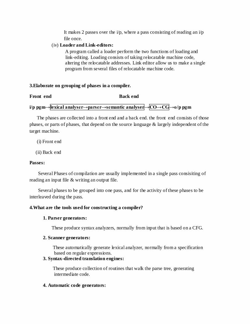
3.Elaborate on grouping of phases in a compiler.
Front end Back end
i/p pgm→lexical analyser→parser→semantic analyser→CO→CG→o/p pgm
The phases are collected into a front end and a back end. the front end consists of those
phases, or parts of phases, that depend on the source language & largely independent of the
target machine.
(i) Front end
(ii) Back end
Passes:
Several Phases of compilation are usually implemented in a single pass consisiting of
reading an input file & writing an output file.
Several phases to be grouped into one pass, and for the activity of these phases to be
interleaved during the pass.
4.What are the tools used for constructing a compiler?
1. Parser generators:
These produce syntax analyzers, normally from input that is based on a CFG.
2. Scanner generators:
These automatically generate lexical analyzer, normally from a specification based on regular expressions. 3. Syntax-directed translation engines:
These produce collection of routines that walk the parse tree, generating
intermediate code. 4. Automatic code generators:

These tool takes a collection of rules define the translation of each operation of the intermediate language into the machine language for the target machine.
5. Data-Flow engines:
It is used to perform good code optimization. It is also used to gathering of
information about how values are transmitted from one part of a program to
each other part.
4. Explain in detail about the Role of Lexical analyzer with possible error recovery actions.
The LA is the first phase of a compiler. Its main task is to read the i/p characters and
produce as o/p a sequence of tokens that the parser uses for syntax analysis.
*Interaction of LA with PARSER
* It may also perform certain secondary tasks
-> Stripping out from the source program comments & white space.
-> Correlating error messages from the compiler with the source program.
-> It may keep track of the number of new line characters seen, so that a
line number can be associated with an error message.
* Issues in lexical analysis
There are several reasons for separating the analysis phase of compiling
into lexical analysis and parsing.
Simpler design
Compiler efficiency is improved
Compiler portability is enhanced
* Lexical Errors
(i)deleting an extraneous character (ii) Inserting a missing character
(iii)Replacing an incorrect character by correct (iv) transporting 2 adjacent characters

5. Elaborate specification of tokens.
-> Token: The meaningful collection of character over the character set of the
programming language is called as the token.
Strings and Languages Parts of a string-Prefix & Suffix
Sequence of s Operations on language
Regular expression Regular definitions Numbers
6. Describe in detail about input buffering.
There are three general approaches to the implementation of a lexical analyzer.
1) Use a lexical- analyzer generator
2) Write the lexical analyzer in a conventional systems
3) Write the lexical analyzer in assembly language and explicitly manage the
reading of the input.
Buffer pairs Sentinels
7. What is a compiler? Explain the various phases of compiler in detail with a neat sketch.
COMPILER:
Compiler is a program that reads a program written in one language –the
source language- and translate it into an equivalent program in other language- the
target language.
Source pgm-> Comiler -> target pgm
Error messages
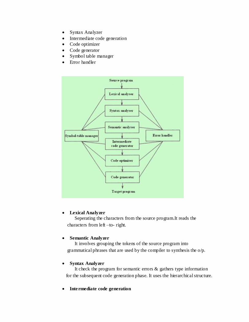
PHASES OF A COMPILER:
There are six phases of the compiler.
Lexical Analyzer
Semantic Analyzer
Syntax Analyzer
Intermediate code generation
Code optimizer
Code generator
Symbol table manager
Error handler
Lexical Analyzer
Seperating the characters from the source program.It reads the
characters from left –to- right.
Semantic Analyzer
It involves grouping the tokens of the source program into
grammatical phrases that are used by the compiler to synthesis the o/p.
Syntax Analyzer
It check the program for semantic errors & gathers type information
for the subsequent code generation phase. It uses the hierarchical structure.
Intermediate code generation

Compiler generate an explicit intermediate representation of the
source program.
Code optimizer
The process of optimizing the best intermediate code is called code
optimization.
Code generator
An intermediate instructions are each translated into a sequence of
machine instructions that perform the same task.
Symbol table manager
To record the identifiers used in the source program and collect the
information about various attributes of each identifier.
Error handler
Detecting & Correcting errors which can be produced by an each
phase.
UNIT-II SYNTAX ANALYSIS
1.What is FIRST and FOLLOW? Explain in detail with an example. Write down the
necessary algorithm.
COMPUTATION OF FIRST:
1.if X is a terminal, then FIRST(x) is X itself
2.if X is a nonterminal, then FIRST(X) is set of terminals derived from X.
=> if X->ε, then FIRST(X) will have ε as its FIRST.
3.consider the production
X->YZ
Y-> ε
Z->a
FIRST(Z)={a}
FIRST(Y)={ ε}
FIRST(X)=( ε)
4.if there is a production X->Y then FIRST(X)=FIRST(Y)
COMPUTATION OF FOLLOW:
1.if S is a starting non terminal , then FOLLOW(S) will have “$” in its FOLLOW
2.if A=>XBY where A,B are non terminals and X,Y are grammar symbols, which may

be either terminals or non terminals then FOLLOW(B)=>FIRST(Y)except ε
3.if A->XB (or) A->XBY and FIRST(Y) has ε, then whatever in FOLLOW(A) will be in
FOLLOW(B)
2.Construct Predictive Parsing table for the following grammar:
S->(L)/a
L->L,S/S
and check wheter the following sentences belong to that grammar or not.
(i)(a,a)
(ii)(a,(a,a))
(iii)(a,((a,a),(a,a)))
STEP1: Eliminate left recursion and left factoring. STEP2: Computation of FIRST for all the left side non terminals STEP3: Computation of FIRST for all the left side non terminals
STEP4: Construction of PARSING TABLE Table consists of terminals in row and non terminals in column
STEP5: Parsing operation The parsing operation can be done by using Stack, i/p string,o/p steps When we get $ symbol in both stack and i/p string the process can be
end. We can process for all the above three inputs.
3.Write in detail about
(i)Recursive descent parsing wit algorithm
(ii) Top down parsing with algorithm.
Solution:
Definition of recursive descent and algorithm. Definition of top down parser, and algorithm for top down parsing
table, parsing method of top down parser.
4.Explain in detail about lexical analyzer generator.
Solution:
Definition Typical program style Transition diagram.
5.Construct predictive parsing table and parse the string id+id*id.
E->E+T|T
T->T*F|F
F->(E)|id
Solution:

Find FIRST and FOLLOW Construct Predictive parsing table Parse te string.
6.Construct predictive parsing table and parse the string NOT(true OR false)
bexpr->bexpr OR bterm | bterm
bterm->bterm AND bfactor | bfactor
bfactor->NOT bfactor | (bexpr) | true | false
Solution:
Find FIRST and FOLLOW and construct table and parse the string.
7.Construct CLR parsing table to parse the sentence id=id*id for the following
grammar.S->L=R|R L-*R|id R->L
Solution:
Find LR(1) items Construct CLR table Parse the string.
8.Construct operator precendence parsing table and parse the string.
S->a| ↑ |(T)
T->T, S |S
Solution:
Compute LEADING and TRAILING Construct operator precedence table Parse the string.
9.Construct LALR parsing table for the grammar.
E->E+T|T
T->T*F|F
F->(E)|id
Solution:
Find LR(1) items Find same core items different second component then merge it After merging construct LALR parsing table.
10.Write algorithms for SLR and CLR string parsing algorithm.
Solution:
Brief introduction about SLR and CLR parsers. Algorithm
UNIT-III [ INTERMEDIATE CODE ENERATION ]

1.How would you generate the intermediate code for the flow of control statements?
Explain with example.
The control statements are if- then-else and while-do. The grammar for such
statements is shown below
S->if E then S1
| if E then S1 else S2
| while E do S1
While generating three address code
To generate new symbolic label the function new_label() is used.
With the expression E.true and E.false are te labels associated.
S.code and E.code is for generating three address code.
s->if E then S1 E.true:=new_label()
E.false:=S.next
S1.next:=S.next
S.code:=E.code||gen_code(E.true‟:‟)||S1.code
=> explain if- then-else and while-do with an example & diagram.
2. What are the various ways of calling procedures? Explain in detail.
=> While calling sequences differ, even for implementations of the same language, the
following action typically take place. Explanations. Example:
s->call id (Elist) { for each item p on queue do
Emit(„param‟p); Emit(„call‟id.place) } Elist->Elist,E
{ append E.place to te end of queue } Elist->E
{ initialize queue to contain only E.place }
3.What is three address code? Mention its types. How would you implement the three
address statements? Explain with examples.
The form of three address code is very much similar to assembly language. Here are
some commonly used three address for typical language constructs. Assignment statement - x:=y op z
Assignment statement - x:= op y
Copy statement - x:=y

Unconditional jump - goto L
Conditional jump - if x relop y goto L
Procedure calls - param x1
Param x2 ………………… Param xn
Call p,n
Return y Array statements - x:=y[i]
X[i]:=y
Address & pointer assignments - x:=&y X:=*y
*x:=y * implementation of three address code @Quadruple representation - op,arg1,arg2,result
@Triples representation - op,arg1,arg2 @Indirect triples representation- listing pointers are used instead of statements.
4.Describe the method of generating syntax directed definition for control statements.
The control statements are if-then-else and while-do. The grammar for such
statements is shown below
S->if E then S1
| if E then S1 else S2
| while E do S1
While generating three address code
To generate new symbolic label the function new_label() is used.
With the expression E.true and E.false are te labels associated.
S.code and E.code is for generating three address code.
s->if E then S1 E.true:=new_label()
E.false:=S.next
S1.next:=S.next
S.code:=E.code||gen_code(E.true‟:‟)||S1.cod
e
Eg: while(i<10)

{ x=0; i=i+1; }
Three address code: L1:if i<10 goto L2 S.begin =new_label()=L1
Goto Lnext E.true =new_label()=L2
L2: x=0 E.code =”if i<10 goto”
I=i+1 E.false=S.next=L.next
Goto L1 S1.code=x=0; i=i+1;
Lnext
5. Give the semantic rules for declarations in a procedure.
* Definition
*semantic rules
P-> {offset:=0}
D->id:T {enter(id.name,T.type,offset);
Offset:=offset+T.width}
T->integer {T.type:=integer, T.width:=4}
T-.>array[num]of T1 {T.type:=array(num.val,T1.type);
T.WIDTH:=num.valXT1.width}
6. How back patching can be used the generate code for Boolean expressions and flow of
control
statements.
Back patching is the activity of filling up unspecified information of label using appropriate
semantic
actions in during the code generation process.
Back patching using Boolean expression
Production rule Semantic Action
E->E1 OR E2 {
backpatch(E1.Flist,M.state);
E.Tlist:=merge(E1.Tlist,E2.Tlist);
E.Flist:=E2.Flist
}
E->(E1) {
E.Tlist:=E1.Flist;
E.Flist:=E1.Tlist;
}
Back patching using Boolean expression

Productions Rewrite the Productions
1)S->if B then S S->if B then M S1
2)S->if B then S else S S->if B then M1S1 N else M2S2
3)M->ε
4)N-> ε
1) {backpatch(B.Tlist,M.state);
S.next:=merge(B.Flist,S1.next)}
2) {backpatch(B.Tlist,M1.state);
backpatch(B.Flist,M2.state);
S.next:=merge(S1.next,merge(N.next,s2.next))}
3){M.state:=nextstate;}
4){N.next:=mklist(nextstate);
Append(„goto_‟);}
7. Explain how types and relative addresses of declared names are computed and how
scope information is dealt with.
When a nested procedure is seen, processing of declarations in the enclosing procedure is
temporarily suspended. This approach will be illustrated by adding semantic rules to the
following language.
P->D
D->D;D | id:T |proc id;D;S
Explanation of above productions
The semantic rules are defined in terms of te following operations:
mktable(previous)
enter(table,name,type,offset)
addwidth(table,width)
enterproc(table,name,newtable)
one example for processing declarations in nested procedure.
8. Describe in detail the syntaxdirected translation of case statements.
The syntax for switch -case statement can be as shown below
Switch expression
{
case value: statement
………………………………..
case value:statement
default : statement
}
Translation scheme for case statement
PRODUCTION RULE

Switch E
{
case v1: s1
casev2: s2
………………
case vn-1:sn-1
default: sn
}
SEMANTIC ACTION
Evaluate E into t suc that t=E
Goto check
L1:code for s1
Goto last
L2:code for s2
Goto last
Ln:code for sn
Goto last
Check:if t=v1 goto L1
If t=v2 goto L2
…………
If t=vn-I goto Ln-1
goto Ln
Last:
9. Explain in detail the translation scheme for addressing array elements.
Semantic actions will be added to the grammar:
(1) S->L:=E
(2) E->E+E
(3) E->(E)
(4) E->L
(5) L->Elist ]
(6) L->id
(1) S->L:=E {if L.offset= null then
Emit(L.place‟:=‟E.place);
Else
Emit(l.place‟[„ L.offset‟]‟‟:=‟E.place)}
(2)E->E+E {E.place:=newtwmp;
Emit(E.place‟:=‟ E1.place‟+‟E2.place)}

(3)E->(E) {E.place:=E1.place}
(4)E->L {if L.offset=null then
E.place:=L.place
Else begin
E.place:=newtemp;
Emit(E.place‟:=‟L.place‟[„L.offset‟]‟)
End }
(5)L->Elist] { L.place:= newtemp;
L.offset:=newtemp;
Emit(L.place „:=‟ c(Elist.array));
Emit(L.offset‟:=‟ Elist.place „*‟ width(Elist.array)) }
(6) L->id { L.place:=id.place; L.offset ;= null }
UNIT IV CODE GENERATION
1. What is the role of code generator in a compiler?
CODE GENERATION
The final phase in our compiler model is the code generator. It takes as input an intermediate representation of the source program and produces as output an equivalent
target program.
The requirements traditionally imposed on a code generator are severe. The output code must
be correct and of high quality, meaning that it should make effective use of the resources of the
target machine. Moreover, the code generator itself should run efficiently.

fig. 1
2. Write in detail the issues in the design of code generator.
ISSUES IN THE DESIGN OF A CODE GENERATOR
While the details are dependent on the target language and the operating system, issues such
as memory management, instruction selection, register allocation, and evaluation order are inherent in
almost all code generation problems.
INPUT TO THE CODE GENERATOR
The input to the code generator consists of the intermediate representation of the source
program produced by the front end, together with information in the symbol table that is used to
determine the run time addresses of the data objects denoted by the names in the intermediate
representation.
There are several choices for the intermediate language, including: linear representations
such as postfix notation, three address representations such as quadruples, virtual machine representations
such as syntax trees and DAGs.
We assume that prior to code generation the front end has scanned, parsed, and translated the source program into a reasonably detailed intermediate representation, so the
values of names appearing in the intermediate language can be represented by quantities that the

target machine can directly manipulate (bits, integers, reals, pointers, etc.). We also assume that the necessary type checking has take place, so type conversion operators have been inserted
wherever necessary and obvious semantic errors (e.g., attempting to index an array by a floating point number) have already been detected. The code generation phase can therefore proceed on
the assumption that its input is free of errors. In some compilers, this kind of semant ic checking is done together with code generation.
TARGET PROGRAMS
The output of the code generator is the target program. The output may take on a variety of
forms: absolute machine language, relocatable machine language, or assembly language.Producing an
absolute machine language program as output has the advantage that it can be placed in a location in
memory and immediately executed. A small program can be compiled and executed quickly. A number
of “student-job” compilers, such as WATFIV and PL/C, produce absolute code.
Producing a relocatable machine language program as output allows subprograms to be
compiled separately. A set of relocatable object modules can be linked together and loaded for execution
by a linking loader. Although we must pay the added expense of linking and loading if we produce
relocatable object modules, we gain a great deal of flexibility in being able to compile subroutines
separately and to call other previously compiled programs from an object module. If the target machine
does not handle relocation automatically, the compiler must provide explicit relocation information to the
loader to link the separately compiled program segments.
Producing an assembly language program as output makes the process of code generation
somewhat easier .We can generate symbolic instructions and use the macro facilities of the assembler to
help generate code .The price paid is the assembly step after code generation.
Because producing assembly code does not duplicate the entire task of the assembler, this choice is
another reasonable alternative, especially for a machine with a small memory, where a compiler must
uses several passes.
MEMORY MANAGEMENT
Mapping names in the source program to addresses of data objects in run time memory is
done cooperatively by the front end and the code generator. We assume that a name in a three-address
statement refers to a symbol table entry for the name.
If machine code is being generated, labels in three address statements have to be converted
to addresses of instructions. This process is analogous to the “back patching”. Suppose that labels refer to
quadruple numbers in a quadruple array. As we scan each quadruple in turn we can deduce the location of
the first machine instruction generated for that quadruple, simply by maintaining a count of the number of

words used for the instructions generated so far. This count can be kept in the quadruple array (in an extra
field), so if a reference such as j: goto i is encountered, and i is less than j, the current quadruple number,
we may simply generate a jump instruction with the target address equal to the machine location of the
first instruction in the code for quadruple i. If, however, the jump is forward, so i exceeds j, we must store
on a list for quadruple i the location of the first machine instruction generated for quadruple j. Then we
process quadruple i, we fill in the proper machine location for all instructions that are forward jumps to i.
INSTRUCTION SELECTION
The nature of the instruction set of the target machine determines the difficulty of instruction
selection. The uniformity and completeness of the instruction set are important factors. If the target
machine does not support each data type in a uniform manner, then each exception to the general rule
requires special handling.
Instruction speeds and machine idioms are other important factors. If we do not care about
the efficiency of the target program, instruction selection is straightforward. For each type of three-
address statement we can design a code skeleton that outlines the target code to be generated for that
construct.
For example, every three address statement of the form x := y + z, where x, y, and z are statically
allocated, can be translated into the code sequence
MOV y, R0 /* load y into register R0 */
ADD z, R0 /* add z to R0 */
MOV R0, x /* store R0 into x */
Unfortunately, this kind of statement – by - statement code generation often produces poor code. For
example, the sequence of statements
a := b + c
d := a + e
would be translated into
MOV b, R0
ADD c, R0
MOV R0, a
MOV a, R0
ADD e, R0
MOV R0, d
Here the fourth statement is redundant, and so is the third if „a‟ is not subsequently used.The quality of
the generated code is determined by its speed and size.
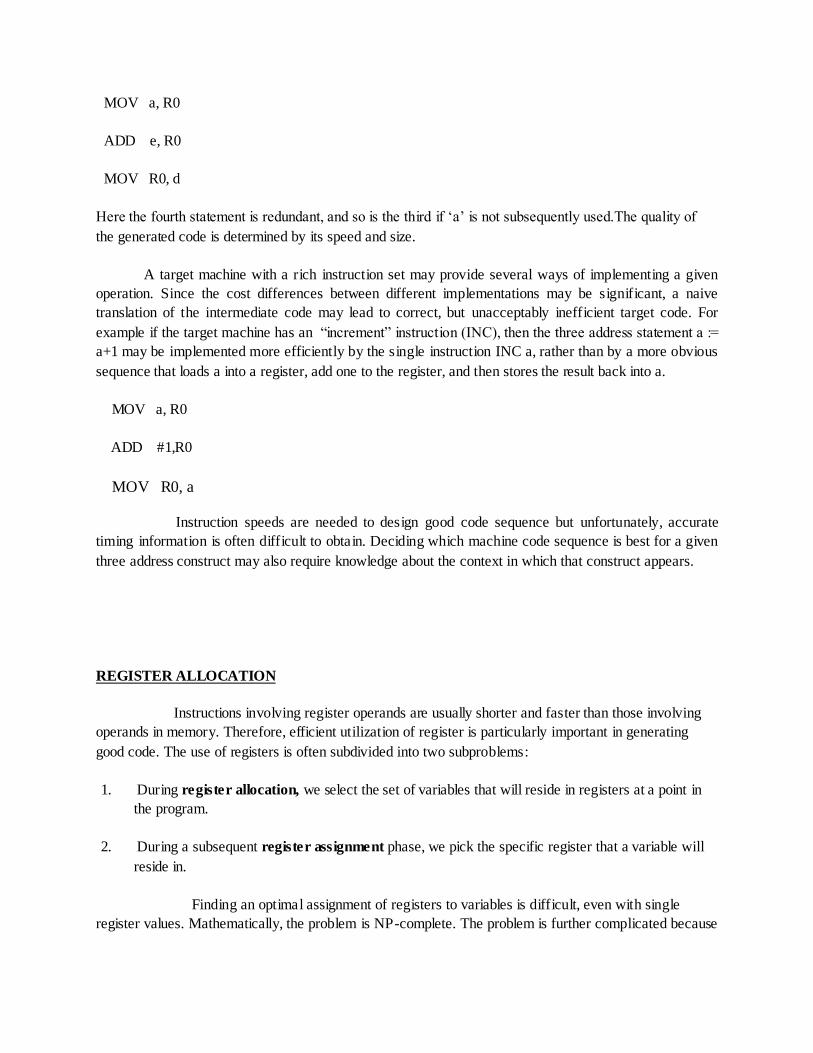
A target machine with a rich instruction set may provide several ways of implementing a given
operation. Since the cost differences between different implementations may be significant, a naive
translation of the intermediate code may lead to correct, but unacceptably inefficient target code. For
example if the target machine has an “increment” instruction (INC), then the three address statement a :=
a+1 may be implemented more efficiently by the single instruction INC a, rather than by a more obvious
sequence that loads a into a register, add one to the register, and then stores the result back into a.
MOV a, R0
ADD #1,R0
MOV R0, a
Instruction speeds are needed to design good code sequence but unfortunately, accurate
timing information is often difficult to obtain. Deciding which machine code sequence is best for a given
three address construct may also require knowledge about the context in which that construct appears.
REGISTER ALLOCATION
Instructions involving register operands are usually shorter and faster than those involving
operands in memory. Therefore, efficient utilization of register is particularly important in generating
good code. The use of registers is often subdivided into two subproblems:
1. During register allocation, we select the set of variables that will reside in registers at a point in
the program.
2. During a subsequent register assignment phase, we pick the specific register that a variable will
reside in.
Finding an optimal assignment of registers to variables is difficult, even with single
register values. Mathematically, the problem is NP-complete. The problem is further complicated because

the hardware and/or the operating system of the target machine may require that certain register usage
conventions be observed.
Certain machines require register pairs (an even and next odd numbered register) for some
operands and results. For example, in the IBM System/370 machines integer multiplication and integer
division involve register pairs. The multiplication instruction is of the form
M x, y
where x, is the multiplicand, is the even register of an even/odd register pair.
The multiplicand value is taken from the odd register pair. The multiplier y is a single
register. The product occupies the entire even/odd register pair.
The division instruction is of the form
D x, y
where the 64-bit dividend occupies an even/odd register pair whose even register is x; y represents the
divisor. After division, the even register holds the remainder and the odd register the quotient.
Now consider the two three address code sequences (a) and (b) in which the only
difference is the operator in the second statement. The shortest assembly sequence for (a) and (b) are
given in(c).
Ri stands for register i. L, ST and A stand for load, store and add respectively. The
optimal choice for the register into which „a‟ is to be loaded depends on what will ultimately happen to t.
t := a + b t := a + b
t := t * c t := t + c
t := t / d t := t / d
(a) (b)
fig. 2 Two three address code sequences
L R1, a L R0, a
A R1, b A R0, b
M R0, c A R0, c
D R0, d SRDA R0, 32
ST R1, t D R0, d

ST R1, t
(a) (b)
fig.3 Optimal machine code sequence
CHOICE OF EVALUATION ORDER
The order in which computations are performed can affect the efficiency of the target code.
Some computation orders require fewer registers to hold intermediate results than others. Picking a best
order is another difficult, NP-complete problem. Initially, we shall avoid the problem by generating code
for the three -address statements in the order in which they have been produced by the intermediate code
generator.
APPROCHES TO CODE GENERATION
The most important criterion for a code generator is that it produce correct code.
Correctness takes on special significance because of the number of special cases that code generator must
face. Given the premium on correctness, designing a code generator so it can be easily implemented ,
tested, and maintained is an important design goal.
3.What are basic blocks and flowgraphs?
BASIC BLOCKS AND FLOW GRAPHS
A graph representation of three-address statements, called a flow graph, is useful for
understanding code-generation algorithms, even if the graph is not explicitly constructed by a code-
generation algorithm. Nodes in the flow graph represent computations, and the edges represent the flow
of control. Flow graph of a program can be used as a vehicle to collect information about the intermediate
program. Some register-assignment algorithms use flow graphs to find the inner loops where a program is
expected to spend most of its time.
BASIC BLOCKS
A basic block is a sequence of consecutive statements in which flow of control enters at the
beginning and leaves at the end without halt or possibility of branching except at the end. The following
sequence of three-address statements forms a basic block:
t1 := a*a
t2 := a*b
t3 := 2*t2
t4 := t1+t3

t5 := b*b
t6 := t4+t5
A three-address statement x := y+z is said to define x and to use y or z. A name in a basic block is said to
live at a given point if its value is used after that point in the program, perhaps in another basic block.
The following algorithm can be used to partition a sequence of three-address statements into basic blocks.
Algorithm 1: Partition into basic blocks.
Input: A sequence of three-address statements.
Output: A list of basic blocks with each three-address statement in exactly one block.
Method:
1. We first determine the set of leaders , the first statements of basic blocks.
The rules we use are the following:
I) The first statement is a leader.
II) Any statement that is the target of a conditional or unconditional goto is a leader.
III) Any statement that immediately follows a goto or conditional goto statement is a leader.
2. For each leader, its basic block consists of the leader and all statements up to but not including the next leader or the end of the program.
Example 3: Consider the fragment of source code shown in fig. 7; it computes the dot product of two
vectors a and b of length 20. A list of three-address statements performing this computation on our target
machine is shown in fig. 8.
begin
prod := 0;
i := 1;
do begin
prod := prod + a[i] * b[i];
i := i+1;

end
while i<= 20
end
fig 7: program to compute dot product
Let us apply Algorithm 1 to the three-address code in fig 8 to determine its basic
blocks. statement (1) is a leader by rule (I) and statement (3) is a leader by rule (II), since the last statement can jump to it. By rule (III) the statement following (12) is a leader. Therefore, statements (1) and (2) form a basic block. The remainder of the program beginning with
statement (3) forms a second basic block.
(1) prod := 0
(2) i := 1
(3) t1 := 4*i
(4) t2 := a [ t1 ]
(5) t3 := 4*i
(6) t4 :=b [ t3 ]
(7) t5 := t2*t4
(8) t6 := prod +t5
(9) prod := t6
(10) t7 := i+1
(11) i := t7
(12) if i<=20 goto (3)
fig 8. Three-address code computing dot product

TRANSFORMATIONS ON BASIC BLOCKS
A basic block computes a set of expressions. These expressions are the values of the
names live on exit from block. Two basic blocks are said to be equivalent if they compute the same set of expressions.
A number of transformations can be applied to a basic block without changing the set of expressions computed by the block. Many of these transformations are useful for
improving the quality of code that will be ultimately generated from a basic block. There are two important classes of local transformations that can be applied to basic blocks; these are the
structure-preserving transformations and the algebraic transformations.
prod := 0
i := 1

4. What are the structure preserving transformations on basic blocks?
Structure-preserving transformations
The primary structure-preserving transformations on basic blocks are:
1. common sub-expression elimination
2. dead-code elimination
3. renaming of temporary variables
4. interchange of two independent adjacent statements
We assume basic blocks have no arrays, pointers, or procedure calls.
1. Common sub-expression elimination
Consider the basic block
a:= b+c
b:= a-d
c:= b+c
d:= a-d
The second and fourth statements compute the same expression,
namely b+c-d, and hence this basic block may be transformed into the equivalent block
a:= b+c
b:= a-d
c:= b+c

d:= b
Although the 1st and 3rd statements in both cases appear to have the same expression on the right, the second statement redefines b. Therefore, the value of b in the 3rd
statement is different from the value of b in the 1st, and the 1st and 3rd statements do not compute the same expression.
2. Dead-code elimination
Suppose x is dead, that is, never subsequently used, at the point where the statement x:= y+z appears in a basic block. Then this statement may be safely removed without changing the value of the basic block.
3. Renaming temporary variables
Suppose we have a statement t:= b+c, where t is a temporary. If we change this
statement to u:= b+c, where u is a new temporary variable, and change all uses of this instance of t to u, then the value of the basic block is not changed. In fact, we can
always transform a basic block into an equivalent block in which each statement that defines a temporary defines a new temporary. We call such a basic block a normal-form block.
4. Interchange of statements
Suppose we have a block with the two adjacent statements
t1:= b+c
t2:= x+y
Then we can interchange the two statements without affecting the value of the block if and only if neither x nor y is t1 and neither b nor c is t2. A normal-form basic block
permits all statement interchanges that are possible.
5.What are the instructions and address modes of the target machine?
The target machine characteristics are
Byte-addressable, 4 bytes/word, n registers
Two operand instructions of the form

op source, destination
Example opcodes: MOV, ADD, SUB, MULT
Several addressing modes
An instruction has an associated cost,cost corresponds to length of instruction
Addressing Modes & Extra Costs

1) Generate target code for the source language statement
“(a-b) + (a-c) + (a-c);”
The 3AC for this can be written as
t := a – b
u := a – c
v := t + u
d := v + u //d live at the end

6.Show the code sequence generated by the simple code generation algorithm What is its cost?
Can it be improved?

Total cost=12
7.What is an activation record? What are the contents of activation record?
Information needed by a single execution of procedure is managed using a contiguous
block of storage called an activation record or frame. It is customary to push the activation record of a
procedure on the run time stack when the procedure is called and to pop the activation record off the stack
when control returns to the caller.

UNIT V CODE OPTIMIZATION AND RUN TIME ENVIRONMENTS
1. What are the phases of code improvement?
The code improvement phase consists of control-flow and data-flow analysis followed
by the application of transformations

.
2. Discuss in detail about principal sources of optimization.
Principal Sources of Optimization
A transformation of a program is called local if it can be performed by looking only at the
statements in a basic block otherwise it is called global. Many transformations can be performed at both
the local and global level levels.
I )Function-preserving transformations
There are number of ways in which compiler can improve without changing the function it
computers.
a)Common sub-expression elimination
b)Copy propagation
c) Dead-code elimination
d) Strength reduction
a) Common sub expression elimination
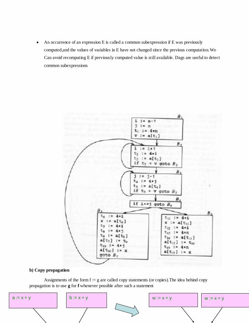
An occurrence of an expression E is called a common subexpression if E was previously
computed,and the values of variables in E have not changed since the previous computation.We
Can avoid recomputing E if previously computed value is still available. Dags are useful to detect
common subexpressions
b) Copy propagation
Assignments of the form f := g are called copy statements (or copies).The idea behind copy
propagation is to use g for f whenever possible after such a statement
a := x + y b := x + y w := x + y
a := w
w := x + y
b := w

c) Dead-code elimination
Dead code includes code that can never be reached and
code that computes a value that never gets used
Consider: if (debug) print …
– It can sometimes be deduced at compile time that the value of an
expression is constant
– Then the constant can be used in place of the expression (constant
Folding)
– Let's assume a previous statement assigns debug := false and

value never changes
– Then the print statement becomes unreachable and can be
eliminated
Consider the example from the previous slide
– The value of x computed by the copy statement never gets used
after the copy propagation
– The copy statement is now dead code and can be eliminated
d) Strength reduction
The replacement of multiplication by a subtraction or addition might be possible when induction
vars are modified in a loop.
II) Loop optimizations (especially inner loops)
Programs tend to spend most of their time in inner loops
We may improve running time by decreasing the number of instructions in an inner loop even while increasing the amount of code outside the loop
III)Code motion
Places loop-invariant computation before the loop E.g.,
j := j - 1
t2 := 4*j
t3 := a[t2]
…
j := j - 1
t2 := t2 - 4
t3 := a[t2]
…

while ( i <= limit-2 ) /* limit is loop invariant */
t = limit – 2;
while ( i <= t ) /* limit, t are loop-invariant */
3. Explain the functions of dataflow analysis?
An optimizing compiler needs
Collect information about the program as a whole Distribute info to each block in the flow graph E.g., knowing which var s are live on exit from each block and using it for register allocation This information is dataflow information and a compiler collects this by dataflow analysis
Info can be collected by setting up and solving systems of equations They relate information at various parts in a program
A dataflow equation is of the form:
out[S] = gen[S] U (in[S] – kill[S])
Meaning: “information at the end of statement (or block) S is either generated within it, or enters at the beginning and is not killed as control flows through it ”
To set up and solve equations, may have to proceed forward or backwards i.e., backwards: define in [S] in terms of out [S]
Equations are normally set up at basic block level
Need to handle complexities involved in function calls and use of pointers
Dataflow Analysis: Examples
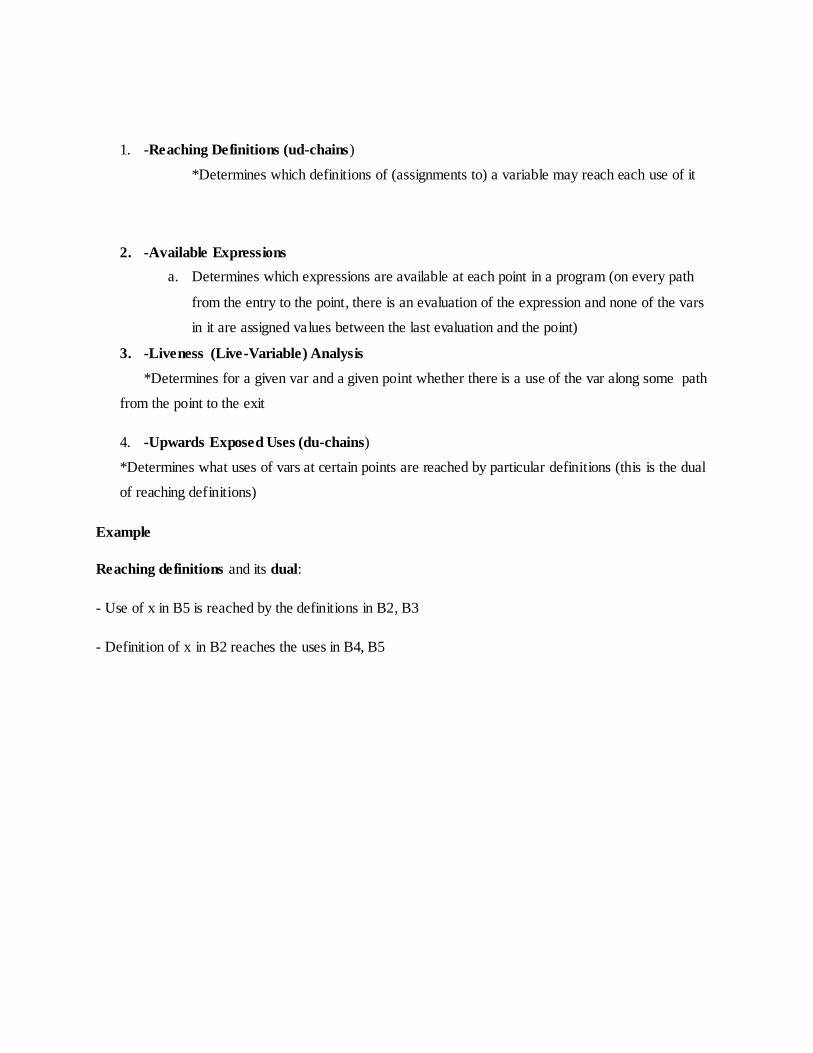
1. -Reaching Definitions (ud-chains)
*Determines which definitions of (assignments to) a variable may reach each use of it
2. -Available Expressions
a. Determines which expressions are available at each point in a program (on every path
from the entry to the point, there is an evaluation of the expression and none of the vars
in it are assigned values between the last evaluation and the point)
3. -Liveness (Live-Variable) Analysis
*Determines for a given var and a given point whether there is a use of the var along some path
from the point to the exit
4. -Upwards Exposed Uses (du-chains)
*Determines what uses of vars at certain points are reached by particular definitions (this is the dual
of reaching definitions)
Example
Reaching definitions and its dual:
- Use of x in B5 is reached by the definitions in B2, B3
- Definition of x in B2 reaches the uses in B4, B5

Copy-Propagation Analysis
Determines that on every path from a copy assignment such as x:= y, to a use of var x there is no assignments to y
Constant-Propagation Analysis
Determines that on every path from an assignment of a constant to a variable, x := k, to a use of x the only assignment to x assign the value k
z > 1
x := 1
z > y
x := 2
z := x - 3 y := x + 1
B2 B3
B4 B5
Y N
Y N

4. How the Optimization performed in Basic Blocks?
Many of the structure-preserving transformations (common sub expression…) can be implemented by constructing a DAG for a basic block.
Common sub expression can be detected by noticing as a new node „m‟ is about to be added, whether there is an existing node „n‟ with the same children, in the same order , and with the
same operator
if so
n computes the same value as m and may be used in its places.
Example
A DAG representation for the block
a := b + c
b := a – d
c := b + c
d := a – d
In the fourth statement d := a-d has the operator – and the nodes a and d as children.
Since the operator and the children are the same as those for the node corresponding to statement two,
we do not create this node newly, but add d to the list of definitions for the node labeled -.
The block of statements are
a := b + c
b := a – d
c := b + c

both b and d are love on exit, then a fourth statement must be used to copy the value from
one to other.
The Use of Algebraic Identities
It is an another important class of optimizations on basic blocks.
Arithmetic Identities
x+0 = 0+x = x
x-0 = x
x*1 = 1*x = x
x/1 = x
Algebraic Identities
x**2 = x*x
x*2.0 = x+x
x/2 = x* 0.5
5. What is an activation tree? Explain its functions.
-Every execution of a procedure is called an ACTIVATION.We can use a tree,called an
activation tree to depict the way control enters and leaves activations.
-The LIFETIME of an activation of procedure P is the sequence of steps between the first and last steps
of P‟s body, including any procedures called while P is running.
-Normally, when control flows from one activation to another, it must (eventually) return to the same
activation.
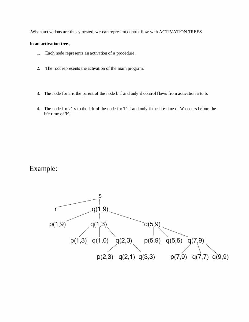
-When activations are thusly nested, we can represent control flow with ACTIVATION TREES
In an activation tree ,
1. Each node represents an activation of a procedure.
2. The root represents the activation of the main program.
3. The node for a is the parent of the node b if and only if control flows from activation a to b.
4. The node for 'a' is to the left of the node for 'b' if and only if the life time of 'a' occurs before the life time of 'b'.
Example:

6.What is the use of control stacks?
The flow of control in a program corresponds to a depth first traversal of the activation
treethat starts at the root,visits anode before its children,and recursively visits children at each
node in a left-to-right order.
We can use a stack,called a control stack to keep track of live procedure activations. The idea
is to push the node for an activation onto the control stack and to pop the node when the
activation ends.
When node 'n' is at the top of the control stack,the stack contains the nodes along the path
from 'n' to the root.
7. What are non-local names?
In a language with nested procedures (or blocks) and static scope (lexical scope), some names are
neither local nor global, they are non-local names.
procedure A
real a;
procedure B
real b;
reference a; // non- local
end B
end A;
8.Explain in detail parameter passing.

Parameter Passing
Parameters Names that appear in the declaration of a procedure are formal parameters. Variables and expressions that are passed to a procedure are actual parameters (or arguments)
Parameter passing modes
-Call by value
-Call by reference
-Copy-restore
-Call by name
Call by value
The actual parameters are evaluated and their r-values are passed to the called procedure . A procedure called by value can affect its caller either through nonlocal names or through pointers.
Parameters in C are always passed by value. Array is unusual, what is passed by value is a pointer.
Pascal uses pass by value by default, but var parameters are passed by reference.
Call-by-Reference
Also known as call-by-address or call-by-location. The caller passes to the called procedure the l-value of the parameter.
If the parameter is an expression, then the expression is evaluated in a new location, and the address of the new location is passed.
Parameters in Fortran are passed by reference
an old implementation bug in Fortran
func(a,b) { a = b};
call func(3,4); print(3);
Copy-Restore
A hybrid between call-by-value and call-by reference.
The actual parameters are evaluated and their r-values are passed as in call-by-value. In
addition, l-values are determined before the call.
When control returns, the current r-values of the formal parameters are copied back into the l-values of the actual parameters.

Call-by-Name
The actual parameters literally substituted for the formals. This is like a macro-expansion or in-line
Call-by-name is not used in practice. However, the conceptually related technique of in- line
expansion is commonly used.
In- lining may be one of the most effective optimization transformations if they are guided by
execution profiles.
Y
N
y := x + 1 z := x - 3 x := 1
z > y