Embed Size (px)
Citation preview
Rodamientos axiales de rodillos cónicos, de doble efecto
Tapered roller thrust bearings, double direction
230
RODAMIENTOS AXIALES DE RODILLOS CÓNICOS, DE DOBLE EFECTO TAPERED ROLLER THRUST BEARINGS, DOUBLE DIRECTION
RODAMIENTOS AXIALES DE RODILLOS CÓNICOS DE DOBLE EFECTO
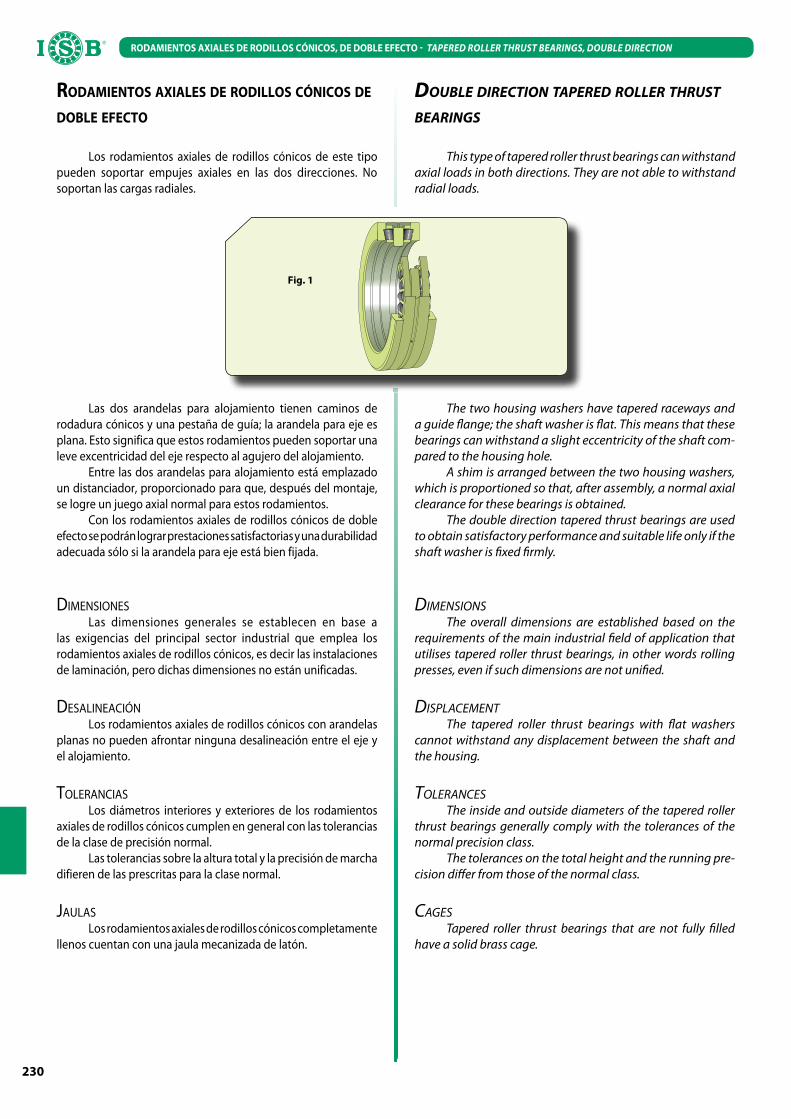
Los rodamientos axiales de rodillos cónicos de este tipo pueden soportar empujes axiales en las dos direcciones. No soportan las cargas radiales.
Las dos arandelas para alojamiento tienen caminos de rodadura cónicos y una pestaña de guía; la arandela para eje es plana. Esto significa que estos rodamientos pueden soportar una leve excentricidad del eje respecto al agujero del alojamiento.
Entre las dos arandelas para alojamiento está emplazado un distanciador, proporcionado para que, después del montaje, se logre un juego axial normal para estos rodamientos.
Con los rodamientos axiales de rodillos cónicos de doble efecto se podrán lograr prestaciones satisfactorias y una durabilidad adecuada sólo si la arandela para eje está bien fijada.
DIMENSIONESLas dimensiones generales se establecen en base a
las exigencias del principal sector industrial que emplea los rodamientos axiales de rodillos cónicos, es decir las instalaciones de laminación, pero dichas dimensiones no están unificadas.
DESALINEACIÓNLos rodamientos axiales de rodillos cónicos con arandelas
planas no pueden afrontar ninguna desalineación entre el eje y el alojamiento.
TOLERANCIASLos diámetros interiores y exteriores de los rodamientos
axiales de rodillos cónicos cumplen en general con las tolerancias de la clase de precisión normal.
Las tolerancias sobre la altura total y la precisión de marcha difieren de las prescritas para la clase normal.
JAULASLos rodamientos axiales de rodillos cónicos completamente
llenos cuentan con una jaula mecanizada de latón.
Fig. 1
DOUBLE DIRECTION TAPERED ROLLER THRUST BEARINGS
This type of tapered roller thrust bearings can withstand axial loads in both directions. They are not able to withstand radial loads.
The two housing washers have tapered raceways and a guide flange; the shaft washer is flat. This means that these bearings can withstand a slight eccentricity of the shaft com-pared to the housing hole.
A shim is arranged between the two housing washers, which is proportioned so that, after assembly, a normal axial clearance for these bearings is obtained.
The double direction tapered thrust bearings are used to obtain satisfactory performance and suitable life only if the shaft washer is fixed firmly.
DIMENSIONSThe overall dimensions are established based on the
requirements of the main industrial field of application that utilises tapered roller thrust bearings, in other words rolling presses, even if such dimensions are not unified.
DISPLACEMENTThe tapered roller thrust bearings with flat washers
cannot withstand any displacement between the shaft and the housing.
TOLERANCESThe inside and outside diameters of the tapered roller
thrust bearings generally comply with the tolerances of the normal precision class.
The tolerances on the total height and the running pre-cision differ from those of the normal class.
CAGESTapered roller thrust bearings that are not fully filled
have a solid brass cage.

RODAMIENTOS AXIALES DE RODILLOS CÓNICOS, DE DOBLE EFECTO
TAPERED ROLLER THRUST BEARINGS, DOUBLE DIRECTION
231
RODAMIENTOS AXIALES DE RODILLOS CÓNICOS, DE DOBLE EFECTO TAPERED ROLLER THRUST BEARINGS, DOUBLE DIRECTION
Dimensiones (mm)Dimension (mm)
Coeficiente de carga (KN)Load rating (KN)
Peso (Kg)Weight (Kg)
SiglaDesignationd
(mm)d1
(mm)D
(mm)D1
(mm)B
(mm)H
(mm)
DinámicoDynamic
C
EstáticoStatic
C0
170 182 240 184 20 84 323,4 1264,2 12,5 350980 C
180 192 280 196 20 90 549,78 2352 22,0 353162
220 231 300 236 22 96 431,2 1626,8 20,0 351019 C
240 251 320 256 22 96 409,64 1862 21,5 351182 C
250 265 380 275 22 100 879,06 4459 43,5 353005
260 276 360 285 20 92 592,9 2548 28,0 350981 C
270 300 450 310 45 180 1617 5880 120 351164 C
320 349 440 355 26 108 970,2 4557 48,5 353102 C
340 470 350 30 130 1274 5586 80 350982 C
350 380 490 390 30 130 1146,6 4998 73,5 351100 C
384 540 400 30 135 1685,6 8967 115 353006
380 416 560 430 32 130 1754,2 9800 110 351175 C
420 455 620 465 35 170 2371,6 11956 185 351121 C
440 480 645 490 50 167 1940,4 10584 190 353152
450 480 645 490 38 155 1940,4 10584 170 350916 D
470 515 720 536 50 200 3341,8 17248 285 353151
530 560 710 575 57 218 2156 10780 245 351475 C
550 585 760 610 50 230 2861,6 12936 310 350976 C
600 670 910 680 70 290 4635,4 20776 655 350901 C
670 705 900 725 50 230 3508,4 18620 425 351761 A
900 960 1180 990 48 220 3939,6 28420 605 353002

2
INTRODUCCIÓN INTRODUCTION
ISB® MARCA SINÓNIMO DE CALIDADUna marca creada por un pool de fabricantes utilizando
elevado knowhow técnico y una maquinaria de avanzada tecnología. La producción abarca todo el sector de los rodamientos estándares; para rodamientos con características técnicas y constructivas particulares está a disposición del cliente una oficina técnica capaz de resolver los problemas inherentes al diseño y a la utilización. Presentamos el programa completo de la producción de los rodamientos estándares ISB®. Este catálogo tiene la función de ayudar y acompañar a los proyectistas de máquinas y equipos, suministrándoles un válido aporte en la búsqueda de los soluciones ideales de empleo de los rodamientos e ilustrar las características técnicas, dimensionales, aplicativas y cualitativas de los rodamientos. La primera parte del catálogo ilustra las características técnicas de todas las series de rodamientos, con las tolerancias dimensionales, el juego de ejecución, la lubricación y otras informaciones técnicas necesarias para la elección del tipo de rodamiento a utilizar. La segunda parte del catálogo incluye las tablas de los rodamientos. En estas tablas los rodamientos están clasificados conforme al tipo de construcción y el diámetro del orificio. Todas las características técnicas constructivas están estandarizadas de conformidad con las normas ISO para suministrar así un producto intercambiable, constante en el tiempo. Todos los productos
ISB® están fabricados de conformidad con la normativa RoHS.
SISTEMA DE CODIFICACIÓN DE LOS RODAMIENTOS El plan general de los rodamientos envolventes métricos
está establecido en la norma ISO 15:1998 (excluidos los rodamientos rodillos cónicos);
los rodamientos radiales métricos de rodillos cónicos están establecidos en la norma ISO 355:1977;
los rodamientos axiales métricos están establecidos en la norma ISO 104:2002;
para otras series se adoptan las siglas “europeas” .La sigla de identificación del rodamiento está formada por
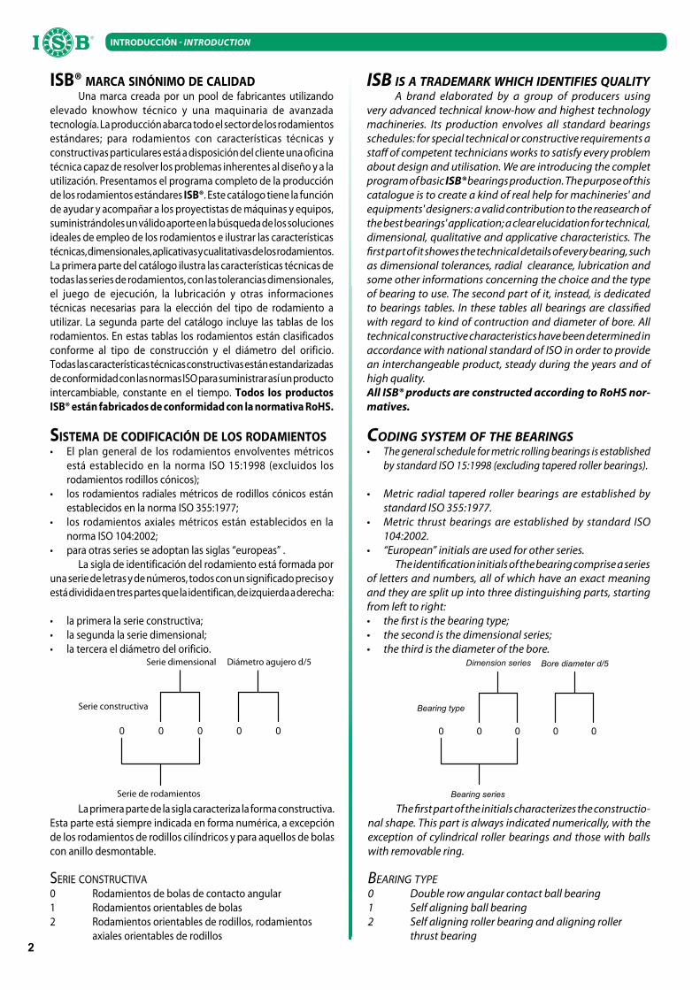
una serie de letras y de números, todos con un significado preciso y está dividida en tres partes que la identifican, de izquierda a derecha:
la primera la serie constructiva; la segunda la serie dimensional; la tercera el diámetro del orificio.
La primera parte de la sigla caracteriza la forma constructiva. Esta parte está siempre indicada en forma numérica, a excepción de los rodamientos de rodillos cilíndricos y para aquellos de bolas con anillo desmontable.
SERIE CONSTRUCTIVA0 Rodamientos de bolas de contacto angular 1 Rodamientos orientables de bolas2 Rodamientos orientables de rodillos, rodamientos axiales orientables de rodillos
ISB IS A TRADEMARK WHICH IDENTIFIES QUALITYA brand elaborated by a group of producers using
very advanced technical know-how and highest technology machineries. Its production envolves all standard bearings schedules: for special technical or constructive requirements a staff of competent technicians works to satisfy every problem about design and utilisation. We are introducing the complet program of basic ISB® bearings production. The purpose of this catalogue is to create a kind of real help for machineries' and equipments' designers: a valid contribution to the reasearch of the best bearings' application; a clear elucidation for technical, dimensional, qualitative and applicative characteristics. The first part of it showes the technical details of every bearing, such as dimensional tolerances, radial clearance, lubrication and some other informations concerning the choice and the type of bearing to use. The second part of it, instead, is dedicated to bearings tables. In these tables all bearings are classified with regard to kind of contruction and diameter of bore. All technical constructive characteristics have been determined in accordance with national standard of ISO in order to provide an interchangeable product, steady during the years and of high quality.All ISB® products are constructed according to RoHS nor-
matives.
CODING SYSTEM OF THE BEARINGS The general schedule for metric rolling bearings is established
by standard ISO 15:1998 (excluding tapered roller bearings).
Metric radial tapered roller bearings are established by standard ISO 355:1977.
Metric thrust bearings are established by standard ISO 104:2002.
“European” initials are used for other series.The identification initials of the bearing comprise a series
of letters and numbers, all of which have an exact meaning and they are split up into three distinguishing parts, starting from left to right: the first is the bearing type; the second is the dimensional series; the third is the diameter of the bore.
The first part of the initials characterizes the constructio-nal shape. This part is always indicated numerically, with the exception of cylindrical roller bearings and those with balls with removable ring.
BEARING TYPE0 Double row angular contact ball bearing1 Self aligning ball bearing2 Self aligning roller bearing and aligning roller thrust bearing
Serie dimensional
Serie de rodamientos
Serie constructiva
Diámetro agujero d/5

3
INTRODUCCIÓN INTRODUCTION
3 Rodamientos de rodillos cónicos4 Rodamientos radiales de dos hileras de bolas5 Rodamientos axiales de bolas6 Rodamientos radiales de una hilera de bolas7 Rodamientos de contacto angular de bolas de una hilera de bolas8 Rodamientos axiales de rodillos cilíndricosN Rodamientos de rodillos cilíndricos Una o más letras después “N” como NJ, NU, NUP, la sigla identifica una subfamilia de los rodamientos de rodillos cilíndricosQJ Rodamientos con cuatro puntos de contacto
La segunda parte de la serie constituye la serie dimensional: se identifican las otras dimensiones del rodamiento, precisamente el diámetro externo y el ancho, expuestos en el diámetro del orificio. Podemos tener, con el mismo orificio y diámetro externo, diversos anchos.
Se distinguen por lo tanto una serie de diámetros y una serie de los anchos.
Tanto las series de los diámetros como también la de los anchos, se indican con números internos de una cifra; ambos números forman precisamente la serie dimensional. De izquierda a derecha, el primer número indica las series de los largos, el segundo la de los diámetros. Su combinación se denomina Serie Dimensional y precede el código del diámetro del orificio. Cuando un rodamiento prevé una sola serie de anchos, el número indicativo de la misma no se escribe. El simbolo de la Serie Dimensional estará compuesto sólo por la cifra que caracteriza la serie de los diámetros.
La tercera parte define el diámetro del orificio y está compuesto por dos cifras según la siguiente codificación: 00 = orificio Ø 10 mm 01 = orificio Ø 12 mm 02 = orificio Ø 15 mm 03 = orificio Ø 17 mm 04 = orificio Ø 20 mm (es decir 20 : 5 = 04) 05 = orificio Ø 25 mm (es decir 25 : 5 = 05)
... hasta: 96 = orificio Ø 480 mm (es decir 480 : 5 = 96)
Para diámetros de orificio de 500 mm incluido y en adelante, después de la parte de la sigla que indica la Serie Dimensional se pone una barra (/) a la cual sigue el diámetro del orificio expresado en milímetros. Ej: 62/500. En el ambito de una determinada serie
3 Tapered roller bearing4 Double row deep groove ball bearing5 Thrust ball bearing6 Deep groove ball bearing7 Angular contact ball bearing
8 Cylindrical roller thrust bearingN Cylindrical roller bearing If there are one or more letters followed “N“ such as NJ, NU, NUP, the code will stand for rib types of bearingsQJ Four point contact ball bearing
The second part of the initials represents the dimensio-nal series: the other dimensions of the bearing are identified, namely the outside diameter and the width, in relation to the diameter of the bore. There may be different widths for the same bore and outside diameter.
A series of diameters and a series of widths are therefore distinguished.
The series of the diameters and that of the widths are both indicated with whole single-figure numbers; these two numbers do indeed form the dimensional series. Starting from left to right, the first number indicates the series of widths and the second the series of diameters. Their combination is called Dimensional Series and comes before the code of the bore diameter. When a bearing has just one series of widths, the relevant indicative number is not written. The symbol of the Dimensional Series will just comprise the figure that characte-rizes the series of diameters.
The third part defines the diameter of the bore and con-sists of two figures according to the following coding system: 00 = bore Ø 10 mm 01 = bore Ø 12 mm 02 = bore Ø 15 mm 03 = bore Ø 17 mm 04 = bore Ø 20 mm (20 : 5 = 04) 05 = bore Ø 25 mm (25 : 5 = 05)
... up to: 96 = bore Ø 480 mm (480 : 5 = 96)
For bore diameters from 500 mm inclusive and larger, after the part of the initials that indicates the Dimensional Series, there will be a slash (/), followed by the diameter of the bore in millimetres. Example: 62/500. For a certain series of be-
Serie dimensional Dimension series
Serie anchura Width series

4
INTRODUCCIÓN INTRODUCTION
de rodamientos las primeras dos partes de la sigla no cambian, mientras es invariable la última parte, es decir aquella que codifica el diámetro del orificio. Esta parte invariable de la sigla, compuesta por forma constructiva y por serie dimensional, generalmente se denomina “serie de rodamientos”.
Serie de rodamientos
Bearing series code
Tipo de rodamiento
Bearing type
Serie de rodamiento
Bearing series code
Serie constructiva
Type of bearing
Serie dimensional
Dimensional series code
Rodamientos radiales de una hilera de bolasSingle row deep grove ball bearing
618 6 18619 6 19160 6 (0)060 6 (1)062 6 (0)263 6 (0)364 6 (0)4
Rodamientos radiales de dos hileras de bolasDouble row deep ball bearings (with filling slot)
42 4 (2)244 4 (2)3
Cojinetes de contacto angular de una hilera de bolasSingle row angular contact ball bearings
719 7 1970 7 (1)072 7 (0)273 7 (0)374 7 (0)4
Rodamientos de contacto angular de dos hileras de bolasDouble row angular contact ball bearing (with filling slot)
32 (0) 3233 (0) 33
Rodamientos con cuatro puntos de contactoFour point contact ball bearing
QJ2 QJ1 (0)2QJ3 QJ1 (0)3
Rodamientos orientables de bolasSelf aligning ball bearing
12 1 (0)222 (1) 2213 1 (0)23 (1) 23
Rodamientos de una hilera de rodillos cilíndricosSingle-row cylindrical roller bearing
NU10 NU 10NU2 NU (0)2
NU22 NU 22NU32 NU 32NU3 NU (0)3
NU23 NU 23NU4 NU (0)4
Rodamientos de rodillos cónicosTapered roller bearing
329 3 29320 3 20330 3 30331 3 31302 3 02322 3 22332 3 32303 3 03313 3 13323 3 23
Rodamientos orientables de rodillosSelf aligning roller thrust bearing
239 2 39230 2 30240 2 40231 2 31241 2 41222 2 22232 2 32213 2 03223 2 23
Rodamientos axiales de bolasSingle direction flat housing washer thrust ball bearing
511 5 11512 5 12513 5 13514 5 14532 5 32533 5 33534 5 34
Rodamientos axiales de bolas de doble efectoDouble direction flat seat housing washer thrust ball bearing
522 5 22523 5 23524 5 24
Rodamientos axiales orientables de rodillosThrust cylindrical roller bearing
292 2 92293 2 93294 2 94
1 - Los números entre paréntesis no deben ser expuestos en el código de la serie de rodamientos
2 - Los rodamientos de rodillos cilindricos incluyen la serie NJ, NUP, N, NF y NU
1 - Width series codeshower in bracket will be default in bearings series code
2 - Cylindrical roller bearing includes NJ, NUP, N, NF, and NU type
arings, the first two parts of the initials remain the same, while the last part changes, in other words the part that codifies the diameter of the bore. This invariable part of the initials, made up of constructional shape and dimensional series, is normally called “series of bearings”.
5
INTRODUCCIÓN INTRODUCTION
ELECCIÓN DEL RODAMIENTOLa elección del rodamiento está dada principalmente por
las características de dimensión y de carga a la cual está sujeto el rodamiento. Las dimensiones y la carga están muchas veces vinculadas al proyecto de la máquina en su conjunto y por lo tanto en muchos casos la elección está limitada a muy pocas tipologías. No existen reglas o tablas precisas, pero generalmente el rodamiento de bolas soporta velocidades elevadas y cargas reducidas, mientras que el rodamiento de rodillos soporta cargas más elevadas pero velocidades inferiores.
Los límites de velocidad de un rodamiento están determinados por la temperatura de funcionamiento. En la elección del rodamiento es importante conocer y considerar los siguientes parámetros: exigencias del servicio; exigencias de durabilidad de la máquina; límites dimensionales del rodamiento; factores negativos (vibraciones, golpes, calor, suciedad, ruido
aceptable, etc).
ELECCIÓN DE LA DIMENSIÓN DE LOS RODAMIENTOS
Las dimensiones de un rodamiento se eligen considerando las condiciones de carga a las cuales estarán sujetos, la durabilidad nominal de servicio y los prescritos parámetros de seguridad de servicio.
COEFICIENTE DE CARGA DINÁMICA DE REFERENCIAPara calcular la dimensión de los rodamientos se adopta
el coeficiente de clasificación de la carga dinámica de referencia C. Dicho parámetro expresa la carga máxima admisible del rodamiento idóneo para suministrar una durabilidad a la fatiga normal equivalente a 1.000.000 de giros. Los coeficientes de carga dinámica de referencia de los rodamientos ISB® han sido determinados de conformidad con las normas ISO 281. Teniendo en cuenta los coeficientes de carga dinámica de referencia se calcula el tiempo de servicio necesario para la aparición de signos de fatiga de los materiales, determinando sobre dicha base la durabilidad teórica. En caso de bajas velocidades de rodamiento, de reducidos movimientos oscilantes o en las aplicaciones estacionarias, se tiene en cuenta el coeficiente de carga estática de referencia C
0.
El coeficiente de carga estática de referencia se define como la carga que se verifica en el rodamiento estacionario. Corresponde a un esfuerzo de contacto calculada entre el cuerpo envolvente mayormente cargado y la pista de rodamiento, equivalente a: 4600 N/mm2 para los rodamientos radiales orientables de bolas. 4200 N/mm2 para los otros rodamientos de bolas. 4.000 N/mm2 para todos los rodamientos de rodillos.
Dicho esfuerzo induce a una deformación permanente del cuerpo y del aro de rodadura, equivalente a aproximadamente 1/10000 (0,0001 dw) del diámetro del cuerpo. Las cargas son de tipo simple y radiales, para los rodamientos radiales, de tipo simple y axiales, para los rodamientos axiales.
COEFICIENTE DE CARGA ESTÁTICACuando el rodamiento es estacionario o está sujeto a
rotaciones u oscilaciones particularmente lentas (inferiores a 10 rpm), el coeficiente de carga estática no se determinará en función de la fatiga del material, sino en base a la deformación permanente inducida en el lugar del punto de contacto entre el cuerpo y el aro
CHOICE OF A BEARINGLoads and dimensions are the most important factors
during the choice of a bearing. These two components are, in the majority of cases, bound to the machinery's project: the choice is therefore restricted to limited cases. Rules or exact tables do not exit usually a ball bearing bears high speeds and low loads, whereas a roller bearing stands lower speeds and higher loads.
Speed limits of a bearing are determined by working temperature. During the choice of it, the following rules have to be followed:
Gravity of operation Machinery's duration Encumbrance limit of the bearing Negative factors, such as: vibration, collision, heat, dirt,
acceptable noise and so on.
SELECTION OF BEARING SIZE.The size of a bearing is selected by considering different
factors, such as its supposed operational life, loads to which it is subjected and prescribed operating safety.
BASIC LOAD RATINGSTo calculate bearings dimensions, the basic dynamic
load rating "C" is used; this factor expresses the admissable load suitable to give a basic rating life up to 1.000.000 revolu-tions. Basic dynamic and static loads rating for ISB® bearings have been determined in accordance with standard ISO 281. Considering the basic dynamic load rating, is calculated the service time until the fatigue of the materials appears, deter-mining in this way the calculated rating life. In the case of low speeds, low oscillating movements or stationary applications, " C
0" basic static load rating is considered.
The basic static load rating is defined as the load acting on the stationary bearing. It corresponds to a calulated contact stress between the most heavily loaded rolling elements and the raceway of:
4600 N/mm2 for self-aligning ball bearings. 4200 N/mm2 for all other ball bearings. 4000 N/mm2 for all roller bearings.
This stress produces a permanent deformation of both rolling elements and raceway, deformation which is about 1/10000 (0,0001 dw) of the rolling element diameter. Loads are pure radial for radial bearings and pure axial for thrust bearings.
STATIC LOAD RATING BEARINGSWhen the bearing is stationary or rotates at very slow
movements or speeds (lower than 10 r/min), basic static load is not determined by the material fatigue but by permanent deformation caused at the rolling elements and the raceway contact.

6
INTRODUCCIÓN INTRODUCTION
de rodadura. Esto es válido también para los rodamientos sujetos a grandes cargas de choque que se verifiquen en el curso de una fracción de giro. En general, el valor de carga podrá aumentar hasta equivaler el coeficiente de carga estática C
0 sin alterar las
características operativas del rodamiento. Se deberá convertir en carga estática equivalente la carga estática combinada (carga radial y axial incidentes simultaneamente). Esto se define como la carga (radial para los rodamientos radiales y axial para los rodamientos axiales) que, si aplicada, causaría en el rodamiento la misma deformación permanente inducible por reales condiciones de carga.
La carga estática equivalente está dada por la formula:
P0 = X
0 F
r + Y
0 F
a
donde:P
0 consiste en la carga estática equivalente, expresada en N;
Fr representa la componente radial de la carga
estática de entidad mayor, expresada en N;F
a representa la componente axial de la carga
estática de entidad mayor, expresada en N;X
0 representa el factor de carga radial;
Y0 representa el factor de carga axial.
DURABILIDAD DE LOS RODAMIENTOSLa durabilidad de los rodamientos se define como el número
de giros, o de horas de funcionamiento, que el rodamiento es capaz de soportar antes que aparezcan los primeros signos de fatiga en uno de sus anillos, o en el aro de rodadura o en los elementos envolventes. Cuando se desee tener en cuenta sólo la fatiga en las superficies de trabajo del rodamiento, se deberán respetar las siguientes condiciones: Las fuerzas y las velocidades que se consideren para la
evaluación del rodamiento deberán corresponder a las que se verifican a las reales condiciones de servicio.
Durante todo el período de servicio deberá garantizarse una adecuada lubricación.
La experiencia demuestra que la razón por la que ceden muchos rodamientos se atribuye a causas diversas a la fatiga, como por ejemplo: elección de un tipo incorrecto de rodamiento, defectos de funcionamiento o de lubricación, presencia de partículas extrañas en el rodamiento u otras causas.
DURACIÓN CON FATIGA NOMINALLa durabilidad con fatiga normal de un rodamiento o de un grupo de
rodamientos idénticos y operantes a idénticas condiciones de servicio, consiste en la durabilidad de servicio equivalente al menos a un grado de fiabilidad del 90%. La durabilidad media de un grupo de rodamientos es muy superior a la durabilidad nominal. La durabilidad a la fatiga nominal se expresa con L
10 (millones
de giros) o L10h
(horas de ejercicio). El valor L10
podrá calcularse con la ecuación:
L10
=(C/P)p
donde:L
10 correspondiente a la durabilidad con fatiga nominal,
expresada en millones de giros;C correspondiente a la carga dinámica del rodamiento, expresada en N;P correspondiente a la carga dinámica equivalente, en el rodamiento expresada en N;p correspondiente al exponente de durabilidad, de la ecuación, con los siguientes valores:P=3 para los rodamientos de bolas.P=10/3 para los rodamientos de rodillos
The same rule is used for rotating bearings standing heavy shock loads which act during a fraction of their revolution. Generally, the value of the load may increase up to the value of the basic static load C
0, without altering the bearing operation properties.
Combined static load (radial and axial load acting together on bearing) must be converted in quivalent static bearing load.
This is defined as the load (radial for radial bearings and axial for thrust bearings), which if applied would cause the same permanent deformation as the real load operatine upon the bearing:
P0 = X
0 F
r + Y
0 F
a
where:P
0 is the equivalent static bearing load, N;
Fr is the radial component of the heaviest static
load, N;F
a is the axial component of the heaviest static
load, N;X
0 is the radial load factor of the bearing;
Y0 is the axial load factor of the bearing.
BEARING LIFEThe life of a bearing can be cosidered as the number of the
revolutions or the number of operating hours, that the bearing is able to endure before the first sign of fatigue appears on one of its ring, on the raceway, on the rolling elements. If we want to consider only the fatigue on the bearing operating surfaces, the following conditions have to be observed:
Forces and loads considered when evaluating the bearing, should correspond to the real operating conditions.
Proper lubrication should be assured during the entire operatine period.
Experience showes that the failure of many bearings does not depend only on fatigue, there are other factors besides this such as: selection of an inadequate bearing type, improper operation or lubrication, outer particles in bearings etc.
BASIC RATING LIFEThe basic rating life of a single bearing or of a group of
identical bearings operating under the same conditions, is the life corresponding to a reliability of 90%. The average life of a group of bearings is higher than the basic rating life. Basic rating life is marked with L10 (millions of revolutions) or with L10h (operating hours). L10 can be calculate using the equation
L10
=(C/P)p
where:L
10 is the basic rating life, in millions of revolution;
C is the basic dynamic load, N;
P is the equivalent dynamic bearing load, N;
p is the exponent of the life equation with the following values;P=3 for ball bearings;P=10/3 for roller bearings;
7
INTRODUCCIÓN INTRODUCTION
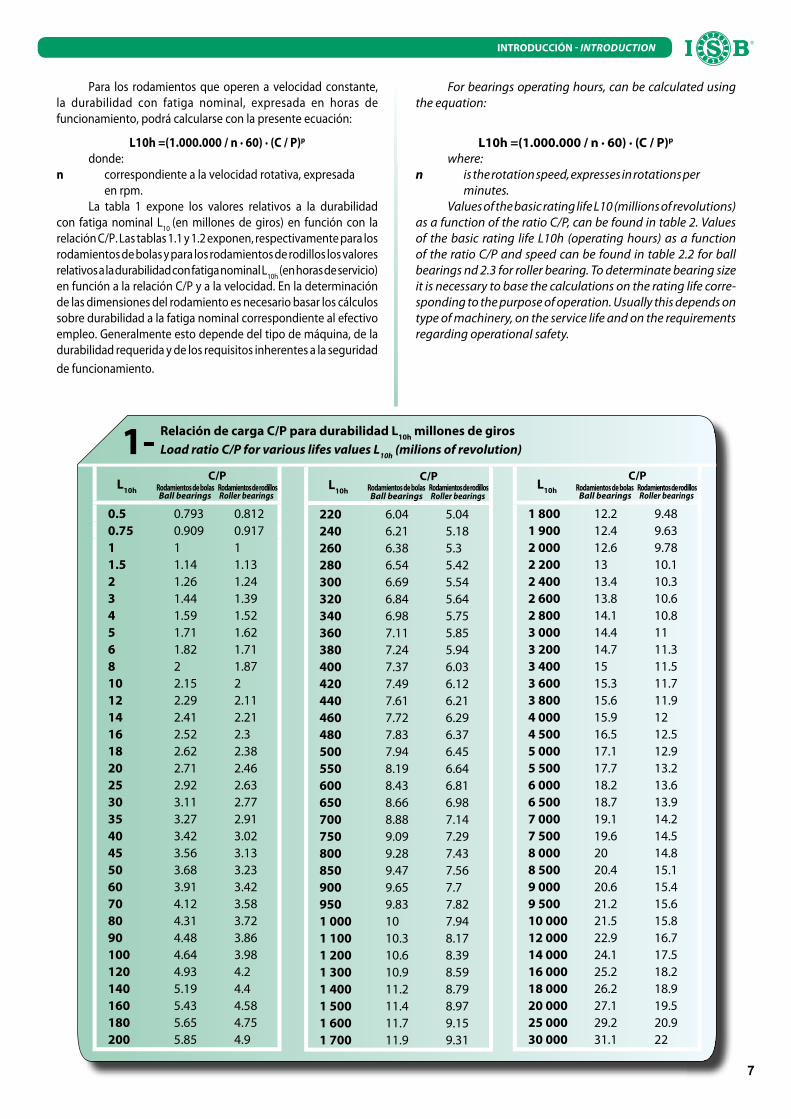
Relación de carga C/P para durabilidad L10h
millones de giros
Load ratio C/P for various lifes values L10h
(milions of revolution)1-
Para los rodamientos que operen a velocidad constante, la durabilidad con fatiga nominal, expresada en horas de funcionamiento, podrá calcularse con la presente ecuación:
L10h =(1.000.000 / n · 60) · (C / P)p
donde:n correspondiente a la velocidad rotativa, expresada en rpm.
La tabla 1 expone los valores relativos a la durabilidad con fatiga nominal L
10 (en millones de giros) en función con la
relación C/P. Las tablas 1.1 y 1.2 exponen, respectivamente para los rodamientos de bolas y para los rodamientos de rodillos los valores relativos a la durabilidad con fatiga nominal L
10h (en horas de servicio)
en función a la relación C/P y a la velocidad. En la determinación de las dimensiones del rodamiento es necesario basar los cálculos sobre durabilidad a la fatiga nominal correspondiente al efectivo empleo. Generalmente esto depende del tipo de máquina, de la durabilidad requerida y de los requisitos inherentes a la seguridad de funcionamiento.
L10h
C/P
Ball bearings Roller bearings
0.5 0.793 0.8120.75 0.909 0.9171 1 11.5 1.14 1.132 1.26 1.243 1.44 1.394 1.59 1.525 1.71 1.626 1.82 1.718 2 1.8710 2.15 212 2.29 2.1114 2.41 2.2116 2.52 2.318 2.62 2.3820 2.71 2.4625 2.92 2.6330 3.11 2.7735 3.27 2.9140 3.42 3.0245 3.56 3.1350 3.68 3.2360 3.91 3.4270 4.12 3.5880 4.31 3.7290 4.48 3.86100 4.64 3.98120 4.93 4.2140 5.19 4.4160 5.43 4.58180 5.65 4.75200 5.85 4.9
L10h
C/P
Ball bearings Roller bearings
220 6.04 5.04240 6.21 5.18260 6.38 5.3280 6.54 5.42300 6.69 5.54320 6.84 5.64340 6.98 5.75360 7.11 5.85380 7.24 5.94400 7.37 6.03420 7.49 6.12440 7.61 6.21460 7.72 6.29480 7.83 6.37500 7.94 6.45550 8.19 6.64600 8.43 6.81650 8.66 6.98700 8.88 7.14750 9.09 7.29800 9.28 7.43850 9.47 7.56900 9.65 7.7950 9.83 7.821 000 10 7.941 100 10.3 8.171 200 10.6 8.391 300 10.9 8.591 400 11.2 8.791 500 11.4 8.971 600 11.7 9.151 700 11.9 9.31
L10h
C/P
Ball bearings Roller bearings
1 800 12.2 9.481 900 12.4 9.632 000 12.6 9.782 200 13 10.12 400 13.4 10.32 600 13.8 10.62 800 14.1 10.83 000 14.4 113 200 14.7 11.33 400 15 11.53 600 15.3 11.73 800 15.6 11.94 000 15.9 124 500 16.5 12.55 000 17.1 12.95 500 17.7 13.26 000 18.2 13.66 500 18.7 13.97 000 19.1 14.27 500 19.6 14.58 000 20 14.88 500 20.4 15.19 000 20.6 15.49 500 21.2 15.610 000 21.5 15.812 000 22.9 16.714 000 24.1 17.516 000 25.2 18.218 000 26.2 18.920 000 27.1 19.525 000 29.2 20.930 000 31.1 22
For bearings operating hours, can be calculated using the equation:
L10h =(1.000.000 / n · 60) · (C / P)p
where:n is the rotation speed, expresses in rotations per minutes.
Values of the basic rating life L10 (millions of revolutions) as a function of the ratio C/P, can be found in table 2. Values of the basic rating life L10h (operating hours) as a function of the ratio C/P and speed can be found in table 2.2 for ball bearings nd 2.3 for roller bearing. To determinate bearing size it is necessary to base the calculations on the rating life corre-sponding to the purpose of operation. Usually this depends on type of machinery, on the service life and on the requirements regarding operational safety.
Rodamientos de bolas Rodamientos de bolas Rodamientos de bolasRodamientos de rodillos Rodamientos de rodillos Rodamientos de rodillos

8
INTRODUCCIÓN INTRODUCTION
Rodamientos de bolas - relación de carga C/P para durabilidad L10h
en horas a diversas velocidades (rpm)
Ball bearings - load ratio C/P for various rating lifes L10h
(operating hours) at various speed n (r/min)1.1-L
10h
C/P cuando n= C/P when n =
50 100 200 300 500 1000 1500 2000
100 0.67 0.84 1.06 1.22 1.44 1.82 2.06 2.29500 1.14 1.44 1.82 2.08 2.47 3.11 3.56 3.911000 1.44 1.82 2.29 2.62 3.11 3.21 4.48 4.931250 1.55 1.96 2.47 2.82 3.35 4.22 4.83 5.311600 1.69 2.13 2.68 3.07 3.63 4.58 5.24 5.772000 1.82 2.29 2.88 3.3 3.91 4.93 5.65 6.212500 1.96 2.47 3.11 3.56 4.22 5.31 6.08 6.693200 2.13 2.68 3.37 3.86 4.58 5.77 6.6 7.274000 2.29 2.88 3.63 4.16 4.93 6.21 7.11 7.835000 2.47 3.11 3.91 4.48 5.31 6.69 7.66 8.436300 2.66 3.36 4.23 4.84 5.74 7.23 8.28 9.118000 2.88 3.63 4.58 5.24 6.21 7.83 8.96 9.8610000 3.11 3.91 4.93 5.65 6.69 8.43 9.65 10.612500 3.35 4.22 5.31 6.08 7.21 9.09 10.4 11.416000 3.63 4.58 5.77 4.6 7.83 9.8 11.3 12.420000 3.91 4.93 6.21 7.11 8.43 10.6 12.2 13.425000 4.22 5.31 6.69 7.66 9.09 11.4 13.1 14.432000 4.58 5.77 7.27 8.32 9.86 12.4 14.2 15.740000 4.93 6.21 7.83 9.86 10.6 13.4 15.3 16.950000 5.31 6.69 8.43 9.65 11.4 14.4 16.5 18.263000 5.74 7.23 9.11 10.4 12.4 15.6 17.8 19.680000 6.21 7.83 9.88 11.3 13.4 16.9 19.3 21.3100000 6.69 8.43 10.6 12.2 14.4 18.2 20.8 22.9200000 8.43 10.6 13.4 15.3 18.2 22.9 26.2 28.8
L10h
C/P cuando n= C/P when n =
3000 4000 5000 8000 10000 15000 20000 30000
100 2.62 2.88 3.11 3.63 3.91 4.48 4.93 5.65500 4.48 4.93 5.31 6.21 6.69 7.66 8.43 9.651000 5.65 6.21 6.69 7.83 8.43 9.65 10.6 12.21250 6.08 6.69 7.21 8.43 9.09 10.4 11.4 13.11600 6.6 7.27 7.83 9.16 9.86 11.3 12.4 14.22000 7.11 7.83 8.43 9.86 10.6 12.2 13.4 15.32500 7.66 8.43 9.09 10.6 11.4 13.1 14.4 16.53200 8.32 9.16 9.86 11.5 12.4 14.2 15.7 17.94000 8.96 9.86 10.6 12.4 13.4 15.3 16.9 19.35000 9.65 10.6 11.4 13.4 14.4 16.5 18.2 20.86300 10.4 11.5 12.4 14.5 15.6 17.8 19.6 22.58000 11.3 12.4 13.4 15.7 16.9 19.3 21.3 24.310000 12.2 13.4 14.4 16.9 18.2 20.8 22.9 26.212500 13.1 14.4 15.5 18.2 19.6 22.4 24.7 28.216000 14.2 15.7 16.9 19.7 21.3 24.3 26.8 30.720000 15.3 16.9 18.2 21.3 22.9 26.2 28.8 3325000 16.5 18.2 19.6 22.9 24.7 28.2 31.1 35.632000 17.9 19.7 21.3 24.9 26.8 30.7 33.7 38.640000 19.3 21.3 22.9 26.8 28.8 33 36.3 41.650000 20.8 22.9 24.7 28.8 31.1 35.6 39.1 44.863000 22.5 24.7 26.6 31.2 33.6 38.4 42.3 48.480000 24.3 26.8 28.8 33.7 36.3 41.6 45.8 52.4100000 26.2 28.8 31.3 36.3 39.1 44.8 49.3 56.5200000 33 36.3 39.1 45.8 49.3 56.5 62.1 71.1

9
INTRODUCCIÓN INTRODUCTION
Rodamientos de rodillos - relación de carga C/P para durabilidad L10h
en horas a diversas velocidades (rpm)
Roller bearings - load ratio C/P for various rating lifes L10h
(operating hours) at various speed n (r/min)1.2-L
10h
C/P cuando n= C/P when n =
50 100 200 300 500 1000 1500 2000
100 0.7 0.86 1.06 1.19 1.39 1.71 1.93 2.11500 1.13 1.39 1.71 1.93 2.25 2.77 3.13 3.421000 1.39 1.71 2.11 2.38 2.77 3.42 3.86 4.21250 1.49 1.83 2.25 2.54 2.97 3.65 4.12 4.51600 1.6 1.97 2.43 2.74 3.19 3.93 4.44 4.842000 1.71 2.11 2.59 2.93 3.42 4.2 4.75 5.182500 1.83 2.25 2.77 3.13 3.65 4.5 5.08 5.543200 1.97 2.43 2.99 3.37 3.93 4.84 5.47 5.964000 2.11 2.59 3.19 3.61 4.2 5.18 5.85 6.375000 2.25 2.77 3.42 3.86 4.5 5.54 6.25 6.816300 2.42 2.97 3.66 4.13 4.82 5.93 6.7 7.38000 2.59 3.19 3.93 4.44 5.18 6.37 7.2 7.8510000 2.77 3.42 4.2 4.75 5.54 6.81 7.7 8.3912500 2.97 3.65 4.5 5.06 5.92 7.29 8.23 8.9716000 3.19 3.93 4.84 5.47 6.37 7.85 8.86 9.6620000 3.42 4.2 5.18 5.85 6.81 8.39 9.48 10.325000 3.65 4.5 5.54 6.25 7.29 8.97 10.1 1132000 3.93 4.84 5.96 6.73 7.85 9.66 10.9 11.940000 4.2 5.18 6.37 7.2 8.39 10.3 11.7 12.750000 4.5 5.54 6.81 7.7 8.97 11 12.5 13.663000 4.82 5.93 7.3 8.25 9.61 11.8 13.4 14.680000 5.18 6.37 7.85 8.86 10.3 12.7 14.4 15.7100000 5.54 6.81 8.39 9.48 11 13.6 15.4 16.7200000 6.81 8.39 10.3 11.7 13.6 16.7 18.9 20.6
L10h
C/P cuando n= C/P when n =
3000 4000 5000 8000 10000 15000 20000 30000
100 2.38 2.59 2.77 3.19 3.42 3.86 4.2 4.75500 3.86 4.2 4.5 5.18 5.54 6.25 6.81 7.71000 4.75 5.18 5.54 6.37 6.81 7.7 8.39 9.481250 5.08 5.54 5.92 6.81 7.29 8.23 8.97 10.11600 5.47 5.96 6.37 7.34 7.85 8.86 9.66 10.92000 5.85 6.37 6.81 7.85 8.39 9.48 10.3 11.72500 6.25 6.81 7.29 8.39 8.97 10.1 11 12.53200 6.73 7.34 7.85 9.03 9.66 10.9 11.9 13.44000 7.2 7.85 8.39 9.66 10.3 11.7 12.7 14.45000 7.7 8.39 8.97 10.3 11 12.5 13.5 15.46300 8.25 8.99 9.61 11.1 11.8 13.4 14.6 16.58000 8.86 9.66 10.3 11.9 12.7 14.4 15.7 17.710000 9.48 10.3 11 12.7 13.6 15.4 16.7 18.912500 10.1 11 11.8 13.6 14.5 16.4 17.9 20.216000 10.9 11.9 12.7 14.6 15.7 17.7 19.3 21.820000 11.7 12.7 13.6 15.7 16.7 18.9 20.6 23.325000 12.5 13.6 14.5 16.7 17.9 20.2 22 24.932000 13.4 14.6 15.7 18 19.3 21.8 23.7 26.840000 14.4 15.7 16.7 19.3 20.6 23.3 25.4 28.750000 15.4 16.7 17.9 20.6 22 24.9 27.1 30.663000 16.5 17.9 19.2 22.1 23.6 26.7 29.1 32.880000 17.7 19.3 20.6 23.7 25.4 28.7 31.2 35.3100000 18.9 20.6 22 25.4 27.1 30.6 33.4 37.7200000 23.3 25.4 27.1 31.2 33.4 37.7 41.1 46.4

10
INTRODUCCIÓN INTRODUCTION
LÍMITE DE VELOCIDADEl límite de velocidad se puede definir como la velocidad
de rotación más elevada que un rodamiento puede alcanzar en función de su empleo, sin comprometer sus prestaciones ni su durabilidad. El límite de velocidad de los rodamientos depende de varios factores como por ejemplo: tipo de rodamiento, magnitud de la carga, clase de tolerancia, configuración de la jaula, juego de trabajo, lubricante, condiciones de lubricación y de refrigeración, etc. En caso de lubricación con aceite, el límite de velocidad podrá ser determinado en modo aproximado, para los rodamientos radiales, en función del diámetro medio del rodamiento y para los rodamientos axiales, en función del diámetro y la carga de montaje del rodamiento. En las tablas de los datos característicos se suministran los límites de velocidad referidos tanto a la lubricación con aceite como también a aquella con grasa. Cuando no se conozcan muy bien las condiciones operativas de los rodamientos y la calidad del lubricante, se aconseja que la velocidad efectiva no supere el 75% de los valores de velocidad suministrados en el presente catálogo. En caso de cargas de gran magnitud, de durabilidad nominal inferior a las 75000 horas de servicio y de rodamientos con diámetro medio superior a 100 mm, los valores de velocidad suministrados por el catálogo deberán ser multiplicados por el factor f. En caso carga combinada, los valores de velocidad suministrados en el catálogo se deberán multiplicar por el factor f1.
CASOS ESPECIALES. BAJAS VELOCIDADESA velocidades significativamente reducidas no se podrá
formar la película de lubricante elastodinámico entre las superficies a contacto del cuerpo envolvente y el aro de rodadura. En este caso se deberán emplear lubricantes con determinados aditivos.
CONDICIONES ESTACIONARIASSi se presentan condiciones estacionarias prolongadas los
rodamientos tenderán a vibrar, los micro-movimientos que se dan en las superficies de contacto entre el elemento envolvente y la pista de deslizamiento podrían dañar estas últimas, con un consecuente aumento de nivel de las vibraciones y disminución de la durabilidad. Resulta además preferible la lubricación con aceite respecto a la grasa.
TOLERANCIAS DE LOS RODAMIENTOSLas tolerancias de los rodamientos han sido normalizadas a
nivel nacional e internacional de conformidad con las normas ISO. Los rodamientos se fabrican en general con clase de tolerancias P0. Bajo demanda, pueden además ser fabricados en clases de tolerancia P6, P5, P4 y P2. Estos últimos rodamientos se emplean para aplicaciones especiales, como guía de alta precisión de árboles o altísimas velocidades de rodamiento. Se suministran tablas para las tolerancias relativas a: dimensiones de los rodamientos; racores, perfiles de montaje.
SPEED LIMITThe speed limit can be defined as the maximum rotation
speed reached by a bearing, without compromising its perfor-mances. The speed limit depends on different factors, such as: type of bearing, magnitude of load, tolerance class, cage design, operational clearance, lubricant, lubrication and cooling con-ditions, and so on. In case of oil lubrication, the bearing speed limit can be approximately determined for radial bearings, as a function of the mean bearing diameter; concerning thrust bearings, instead, speed limit is determined as a function of the dimension and weight of the bearing's ounting.In bearing tables, the value of speed limit are given for both grease and oil lubrication. In the case of insufficient informations about quality of lubrication and operating conditions, the effective speed is recommended not to exceed the 75% of the speed in-dicated in this catalogue. In the case of heavy loads, when the rating life is shorter than 75000 operating hours and bearing mean diameter is larger than 1000 mm, speed limits indicated in this catalogue, have to be mul tiplied by factor "f". If the load is combined, the speed from this catalogue have to be multiplied by factor "f1".
SPECIAL CASE. LOW SPEEDSAt very low speeds it is impossible the formation of an
elastohydrodinamic lubricant film between the rolling elements and raceway. Lubrificants with special additives should be used in such cases.
STATIONARY CONDITIONSIf in long term stationary conditions, bearings start vi-
brating, the micromovement at the rolling elements and at the raceway contacts produces damages on the contact surfaces. In this way vibration level is increased and the life is shorter. Oil lubrication is preferable to grease lubrication.
BEARINGS TOLERANCESIn accordance with ISO rules bearing tolerances have
been nationally and internationally standardized. Bearings are usually manufactured to the tolerance class P0. Under request they can be supplied with P6, P5, P4 and P2 tolerance classes. These latter bearings are used for special applications, such us very high speeds or very accurate shaft guidance. The value of the limit for these tolerance classes are given for:
dimensions of bearings; mounting chamfer.

11
INTRODUCCIÓN INTRODUCTION
SÍMBOLOS d Diámetro nominal del orificiod
mp Diámetro medio del orificio
Vdp
Variación del diámetro del orificioV
dmp Variación del diámetro medio del orificio
Δdmp
Diferencia del diámetro del orificio respecto al valor nominal (Δd
mp = d
mp – d)
D Diámetro nominal externoD
mp Diámetro externo medio
VDp
Variación del diámetro externoV
Dmp Variación del diámetro externo medio
ΔDmp
Diferencia del diámetro externo medio respecto al valor nominal (ΔD
mp = D
mp – D)
Kia
Concentricidad de rotación del aro interior en el rodamiento completoK
ea Concentricidad de rotación del aro exterior en el rodamiento
completoB Medida nominal de la altura del aro interiorC Medida nominal de la altura del aro exteriorB
s Medida individual de la altura del aro interior
Cs Medida individual de la altura del aro exterior
ΔBs Diferencia de una única medida de la altura del aro
interior (ΔBs = B
s – B)
ΔCs Diferencia de una única medida de la altura del aro
exterior (ΔCs = C
s – C)
Sd Defecto de cuadratura de las caras respecto al orificio
del aro interiorS
D Variación de la inclinación cilíndrica exterior respecto
a la superficie lateral del aro exteriorS
ia Planeidad de rotación de la superficie lateral del aro interior
respecto al camino de rodadura en el rodamiento rígido completoS
ea Planeidad de rotación de la superficie lateral del aro exterior
respecto al camino de rodadura en el rodamiento rígido completo T Medida nominal del ancho del rodamientoT
s Ancho total de un rodamiento de rodillos cónicos
T1s
Ancho total del rodamiento de rodillos cónicos, con el cono montado en una copa muestraT
2s Ancho total del rodamiento de rodillos cónicos,
con la copa montada en un cono muestraΔT
s Diferencia de la medida individual del ancho del
rodamiento de rodillos cónicos respecto al valor nominal (ΔT
s = T
s – T)
ΔT1s
Diferencia de la medida individual del ancho del rodamiento de rodillos cónicos respecto al valor nominal (ΔT
1s = T
1s – T)
ΔT2s
Diferencia de la medida individual del ancho del rodamiento de rodillos cónicos respecto al valor nominal (ΔT
2s = T
2s – T)
SYMBOLSd Nominal bore diameterd
mp mean bore diameter
Vdp
Bore diameter variationV
dmp Mean bore diameter variation
Δdmp
Deviation of bore diameter from nominal value (Δd
mp = d
mp – d)
D Nominal outer diameterD
mp Mean outer diameter
VDp
Outer diameter variationV
Dmp Mean outer diameter variation
ΔDmp
Deviation of the mean outer diameter from nominal value (ΔD
mp = D
mp – D)
Kia
Concentricity radial run out of assembled bearing inner ringK
ea Concentricity radial run out of assembled
bearing outer ringB Nominal height of the inner ringC Nominal height of the outer ringB
s Single height of the inner ring
Cs Single height of the outer ring
ΔBs Inner ring single height deviation as
regards to nominal dimension (ΔBs = B
s – B)
ΔCs Outer ring single height deviation as
regards to nominal dimension (ΔCs = C
s – C)
Sd Side face run out with reference to bore of
the inner ring S
D Variation in inclination of outside cylindrical
surface to outer ring side faceS
ia Revolution flatness of inner ring side surface,
as regards to the raceway of complete bearing
Sea
Revolution flatness of outer ring side surface, as regards to the raceway of complete bearing
T Nominal width of bearing T
s Total width of tapered roller bearing
T1s
Total width of tapered roller bearing, with the cone assembled on a sample torqueT
2s Total width of tapered roller bearing, with
the torque assembled on a sample coneΔT
s Deviation of single measurement concerning
the width of tapered roller bearing, from nominal value (ΔT
s = T
s – T)
ΔT1s
Deviation of single measurement concerning the width of tapered roller bearing, from nominal value (ΔT
1s = T
1s – T)
ΔT2s
Deviation of single measurement concerning the width of tapered roller bearing, from nominal value (ΔT
2s = T
2s – T)

12
INTRODUCCIÓN INTRODUCTION
Tolerancias para rodamientos radiales de la clase de precisión normal (excluidos los rodamientos de rodillos cónicos)
Tollerances for radial bearings normal precision (tapered roller bearings excluded)
Anillo interno - Inner ring μm : 0.001 mm
d Δdmp
Vdp
Vdmp
ΔBs
VBs
Kia
Serie diametral - Diameters series
más de - over hasta - up to máx mín 8,9 max 0,1 max 2,3,4 max máx máx mín máx máx
mm mm μm μm μm μm μm μm μm μm μm μm
2,5 10 0 -8 10 8 6 6 0 -120 15 1010 18 0 -8 10 8 6 6 0 -120 20 1018 30 0 -10 13 10 8 8 0 -120 20 1330 50 0 -12 15 12 9 9 0 -120 20 1550 80 0 -15 19 19 11 11 0 -150 25 2080 120 0 -20 25 25 15 15 0 -200 25 25120 180 0 -25 31 31 19 19 0 -250 30 30180 250 0 -30 38 38 23 23 0 -300 30 40250 315 0 -35 44 44 26 26 0 -350 35 50315 400 0 -40 50 50 30 30 0 -400 40 60400 500 0 -45 56 56 34 34 0 -450 50 65500 630 0 -50 63 63 38 38 0 -500 60 70630 800 0 -75 - - - - 0 -750 70 80800 1000 0 -100 - - - - 0 -1000 80 901000 1250 0 -125 - - - - 0 -1250 100 1001250 1600 0 -160 - - - - 0 -1600 120 1201600 2000 0 -200 - - - - 0 -2000 140 140
Anillo externo - Outer ring
D ΔDmp
VDp
*Rodamientos con blindajes estancos
Sealed bearings
VDmp
Kea
Serie diametrales - Diameters series
más de - over hasta - up to máx mín 8,9 max 0,1 max 2,3,4 max max max max
mm mm μm μm μm μm μm μm μm μm
6 18 0 -8 10 8 6 10 6 1518 30 0 -9 12 9 7 12 7 1530 50 0 -11 14 11 8 16 8 2050 80 0 -13 16 13 10 20 10 2580 120 0 -15 19 19 11 26 11 35120 150 0 -18 23 23 14 30 14 40150 180 0 -25 31 31 19 38 19 45180 250 0 -30 38 38 23 - 23 50250 315 0 -35 44 44 26 - 26 60315 400 0 -40 50 50 30 - 30 70400 500 0 -45 56 56 34 - 34 80500 630 0 -50 63 63 38 - 38 100630 800 0 -75 94 94 55 - 55 120800 1000 0 -100 125 125 75 - 75 1401000 1250 0 -125 - - - - - 1601250 1600 0 -160 - - - - - 1901600 2000 0 -200 - - - - - 2202000 2500 0 -250 - - - - - 250
* Aplicable solo a los rodamientos de la serie diametrales 2, 3, 4.
* Applicable only to bearings 2, 3, 4 diameter series
13
INTRODUCCIÓN INTRODUCTION
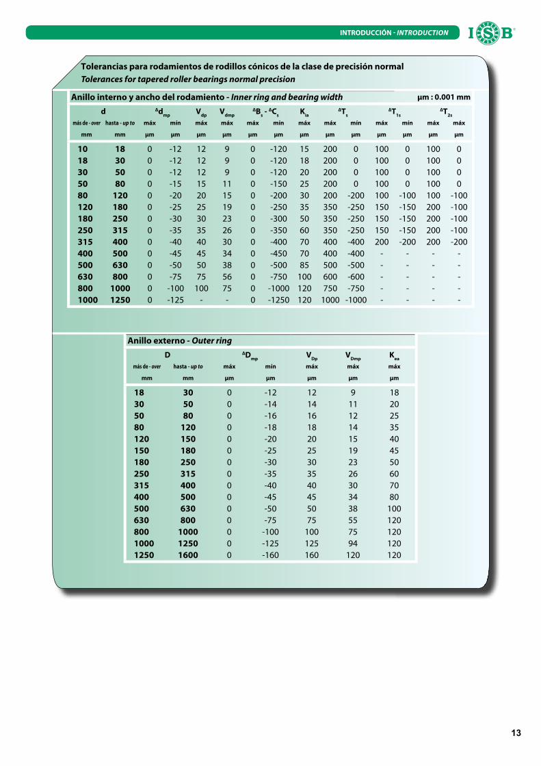
Tolerancias para rodamientos de rodillos cónicos de la clase de precisión normal
Tolerances for tapered roller bearings normal precision
Anillo interno y ancho del rodamiento - Inner ring and bearing width μm : 0.001 mm
d Δdmp
Vdp
Vdmp
ΔBs - ΔC
s K
ia
ΔTs
ΔT1s
ΔT2s
más de - over hasta - up to máx mín máx máx máx mín máx máx mín máx mín máx máx
mm mm μm μm μm μm μm μm μm μm μm μm μm μm μm
10 18 0 -12 12 9 0 -120 15 200 0 100 0 100 018 30 0 -12 12 9 0 -120 18 200 0 100 0 100 030 50 0 -12 12 9 0 -120 20 200 0 100 0 100 050 80 0 -15 15 11 0 -150 25 200 0 100 0 100 080 120 0 -20 20 15 0 -200 30 200 -200 100 -100 100 -100120 180 0 -25 25 19 0 -250 35 350 -250 150 -150 200 -100180 250 0 -30 30 23 0 -300 50 350 -250 150 -150 200 -100250 315 0 -35 35 26 0 -350 60 350 -250 150 -150 200 -100315 400 0 -40 40 30 0 -400 70 400 -400 200 -200 200 -200400 500 0 -45 45 34 0 -450 70 400 -400 - - - -500 630 0 -50 50 38 0 -500 85 500 -500 - - - -630 800 0 -75 75 56 0 -750 100 600 -600 - - - -800 1000 0 -100 100 75 0 -1000 120 750 -750 - - - -1000 1250 0 -125 - - 0 -1250 120 1000 -1000 - - - -
Anillo externo - Outer ring
D ΔDmp
VDp
VDmp
Kea
más de - over hasta - up to máx mín máx máx máx
mm mm μm μm μm μm μm
18 30 0 -12 12 9 1830 50 0 -14 14 11 2050 80 0 -16 16 12 2580 120 0 -18 18 14 35120 150 0 -20 20 15 40150 180 0 -25 25 19 45180 250 0 -30 30 23 50250 315 0 -35 35 26 60315 400 0 -40 40 30 70400 500 0 -45 45 34 80500 630 0 -50 50 38 100630 800 0 -75 75 55 120800 1000 0 -100 100 75 1201000 1250 0 -125 125 94 1201250 1600 0 -160 160 120 120

14
INTRODUCCIÓN INTRODUCTION
Tolerancias para orificios cónicos
Tolerances for conical bore
Conicidad 1 : 12 - Taper-ratio 1 : 12 μm : 0.001 mm
Clase de tolerancia normal, P6Normal class of tollerance, P6
Clase de tolerancia normal, P5Normal class of tollerance, P5
d Δdmp
Vdp
1) Δd1mp
-Δdmp
Δdmp
Vdp
1) Δd1mp
-Δdmp
más de - over hasta - up to máx mín máx 0,1 max 2,3,4 max máx mín mín máx máx
mm mm μm μm μm μm μm μm μm μm μm μm
18 30 21 0 13 21 0 13 0 13 13 030 50 25 0 15 25 0 16 0 15 16 050 80 30 0 19 30 0 19 0 19 19 080 120 35 0 25 35 0 22 0 22 22 0120 180 40 0 31 40 0 25 0 25 25 0180 250 46 0 38 46 0 29 0 29 29 0250 315 52 0 44 52 0 32 0 32 32 0315 400 57 0 50 57 0 36 0 36 36 0400 500 63 0 56 63 0 40 0 - 40 0500 630 70 0 - 70 0 44 0 - 44 0630 800 80 0 - 80 0 50 0 - 50 0800 1000 90 0 - 90 0 56 0 - 56 0
Conicidad 1 : 30 - Taper-ratio 1 : 30 μm : 0.001 mm
Clase de tolerancia normalNormal class of tollerance
d Δdmp
Vdp
1) Δd1mp
-Δdmp
más de - over hasta - up to máx mín máx 0,1 max 2,3,4 max
mm mm μm μm μm μm μm
80 120 20 0 25 40 0120 180 25 0 31 50 0180 250 30 0 38 55 0250 315 35 0 44 60 0315 400 40 0 50 65 0400 500 45 0 56 75 0500 630 50 0 63 85 0630 800 75 0 100 0800 1000 100 0 100 0
1) Valido en cada uno de los planos del orificio.
1) Valid for every radial flat of bore.
Orificios cónicos
Conical bore
Semiángulo del cono α:Half angle of cone α:
α = 2°23’9,4” (conicidad 1:12)(taper-ratio 1:12)
α = 0°57’17,4” (conicidad 1:30)(taper-ratio 1:30)
Diámetro mayor teórico d1:Theoretical bigger diameter d1:
d1 = d + (1/12) · B (conicidad 1:12)(taper-ratio 1:12)
d1 = d + (1/30) · B (conicidad 01:30)(taper-ratio 1:30)

15
INTRODUCCIÓN INTRODUCTION
Tolerancia para rodamientos axiales
Tolerances for axial bearings
Anillo para eje - Shaft locating washer
Clase de tolerancia normal, P6, P5Normal class of tollerance, P6, P5
d Δdmp
Vdp
Si
1) Si
1) Si
1)
más de - over hasta - up to máx mín máx máx máx máx
mm mm μm μm μm μm μm μm
- 18 0 -8 6 10 5 318 30 0 -10 8 10 5 330 50 0 -12 9 10 6 350 80 0 -15 11 10 7 480 120 0 -20 15 15 8 4120 180 0 -25 19 15 9 5180 250 0 -30 23 20 10 5250 315 0 -35 26 25 13 7315 400 0 -40 30 30 15 7400 500 0 -45 34 30 18 9500 630 0 -50 38 35 21 11630 800 0 -75 - 40 25 13800 1000 0 -100 - 45 30 151000 1250 0 -125 - 50 35 18
1) Valores excluidos para los rodamientos axiales orientables de rodillos. Para rodamientos con el mismo Ø externo los valores son los mismos tanto para rodamientos de doble efecto como también de simple efecto.
1) These value are not valid for axial roller bearings for bearings having the same outer diameter. Value are the same for both double acting and single acting bearings.
Anillo para alojamiento - Housing locating washer
Clase de tolerancia normal, P6, P5Normal class of tollerance, P6, P5
D ΔDmp
VDp
Si
1) Si
1) Si
1)
más de - over hasta - up to máx mín máx máx máx máx
mm mm μm μm μm μm μm μm
18 30 0 -13 10 10 5 330 50 0 -16 12 10 6 350 80 0 -19 14 10 7 480 120 0 -22 17 15 8 4120 180 0 -25 19 15 9 5180 250 0 -30 23 20 10 5250 315 0 -35 26 25 13 7315 400 0 -40 30 30 15 7400 500 0 -45 34 30 18 9500 630 0 -50 38 35 21 11630 800 0 -75 55 40 25 13800 1000 0 -100 75 45 30 151000 1250 0 -125 - 50 35 18
Altura del rodamiento - Bearing width
d ΔTs
ΔT1s
ΔT2s
ΔT3s
ΔT4s
más de - over hasta - up to máx mín máx mín máx mín máx mín máx mín
mm mm μm μm μm μm μm μm μm μm μm μm
- 30 20 -250 100 -250 150 -400 300 -400 20 -30030 50 20 -250 100 -250 150 -400 300 -400 20 -30050 80 20 -300 100 -300 150 -500 300 -500 20 -40080 120 25 -300 150 -300 200 -500 400 -500 25 -400120 180 25 -400 150 -400 200 -600 400 -600 25 -500180 250 30 -400 150 -400 250 -600 500 -600 30 -500250 315 40 -400 200 -400 350 -700 600 -700 40 -700315 400 40 -500 200 -500 350 -700 600 -700 40 -700400 500 50 -500 300 -500 400 -900 750 -900 50 -900500 630 60 -600 350 600 500 -1100 900 -1100 60 -1200630 800 70 -750 400 -750 600 -1300 1100 -1300 70 -1400800 1000 80 -1000 450 -1000 700 -1500 1300 -1500 80 -18001000 1250 100 -1400 500 -1400 900 -1800 1600 -1800 100 -2400

16
INTRODUCCIÓN INTRODUCTION
Tabla juego radial de los rodamientos de bolas
Tables of radial clearence for ball bearings
Rodamientos de bolas - Ball bearings
Diámetro del orificioBore diameter
C2NormalNormal
C3 C4 C5
más de - over hasta - up to máx mín máx mín máx mín máx mín máx mín
mm mm μm μm μm μm μm μm μm μm μm μm
2.5 10 0 7 2 13 8 23 14 29 20 3710 18 0 9 3 18 11 25 18 33 25 4518 24 0 10 5 20 13 28 20 36 28 4824 30 1 11 5 20 13 28 23 41 30 5330 40 1 11 6 20 15 33 28 46 40 6440 50 1 11 6 23 18 36 30 51 45 7350 65 1 15 8 28 23 43 38 61 55 9065 80 1 15 10 30 25 51 46 71 65 10580 100 1 18 12 36 30 58 53 84 75 120100 120 2 20 15 41 36 66 61 97 90 140120 140 2 23 18 48 41 81 71 114 105 160140 160 2 23 18 53 46 91 81 130 120 180160 180 2 25 20 61 53 102 91 147 135 200180 200 2 30 25 71 63 117 107 163 150 230200 225 2 35 30 85 77 137 127 195 180 270225 250 2 40 33 95 87 157 147 225 210 300250 280 2 45 35 100 90 170 157 245 230 340280 315 3 55 45 115 105 190 175 270 250 370315 355 3 55 45 125 115 210 195 300 280 400355 400 3 65 55 145 135 240 225 340 320 460400 450 5 80 65 170 150 270 250 380 360 510450 500 5 90 75 190 170 300 280 420 400 570500 560 10 100 80 210 190 335 310 475 450 640560 630 10 110 90 230 210 365 340 525 500 700630 710 10 120 90 250 220 390 360 570 540 760710 800 10 130 100 270 240 420 390 620 590 840800 900 20 150 110 300 260 460 420 680 640 920
JUEGO RADIAL DE LOS RODAMIENTOS DE BOLAS Y DE RODILLOS
Uno de los principales factores que influencian la durabilidad de los rodamientos de bolas y de rodillos es el juego radial, determinado como el valor medio de varias medidas del desplazamiento total sobre el plano perpendicular al eje del rodamiento. Dicho desplazamiento es típico de uno de los anillos del rodamiento (el otro es estacionario) durante la rotación en varias direcciones angulares, tanto respecto al anillo rotativo como también respecto al estacionario, y a diversas posiciones angulares de la serie de bolas o rodillos respecto a los anillos mismos.
Considerados los diversos coeficientes de juego requeridos en la entrega, los rodamientos radiales se realizan según varios grupos de juego inicial. En general, los rodamientos radiales de bolas y de rodillos se realizan según el grupo de juego radial normal, que, en empleos comunes a la mayor parte de los casos, suministran parámetros satisfactorios de funcionamiento. El juego radial se evidencia con el agregado a la sigla del rodamiento de la designación de la clase de precisión (C2, C3, C4, C5). A los rodamientos fabricados con juego radial correspondiente al grupo normal no se asignan ulteriores designaciones convencionales. Las siguientes tablas recogen los valores de juego radial.
RADIAL CLEARANCE OF BALL AND ROLLER BEARINGS
One of the most important factor influencing the life of a roller or ball bearing, is the radial clearance.The latter is determined by a mean of several measurements of total di-splacement in the plane perpendicular to the bearing axle. This displacement is typical for one of the bearing ring (the other is stationary) during its rotation in different angular directions, oth with respect to the rotable ring and the stationary one, and a different angular positions of the set of balls or rollers with respect to the bearing races.
Because of the different requirements concerning the radial clearance, bearings are manufactured with several initial clearance groups, such as additional groups. Radial bearings are usually manufactured in accordance with the normal clearance group: this enables a satisfactory functioning of the bearing, in the majority of cases. Radial clearance is pointed out by adding the precision class (C2, C3, C4, C5) to bearing group. No further conventional designations are assigned to normal clearance bearings. Values of radial clearances are given below, see tables.

17
INTRODUCCIÓN INTRODUCTION
Tabla juego radial
Tables of radial clearence
Rodamientos radiales de rodillos cilíndricos - Cylindrical roller bearings
Diámetro del orificioBore diameter
C2NormalNormal
C3 C4 C5
más de - over hasta - up to máx mín máx mín máx mín máx mín máx mín
mm mm μm μm μm μm μm μm μm μm μm μm
- 10 0 30 10 40 25 55 35 65 - -10 18 0 30 10 40 25 55 35 65 55 8518 24 0 30 10 40 25 55 35 65 55 8524 30 0 30 10 45 30 65 40 70 60 9030 40 0 35 15 50 35 70 45 80 70 10540 50 5 40 20 55 40 75 55 90 85 12050 65 5 45 20 65 45 90 65 105 100 14065 80 5 55 25 75 55 105 75 125 115 16580 100 10 60 30 80 65 115 90 140 145 195100 120 10 65 35 90 80 135 105 160 165 220120 140 10 75 40 105 90 155 115 180 185 250140 160 15 80 50 115 100 165 130 195 210 275160 180 20 85 60 125 110 175 150 215 235 300180 200 25 95 65 135 125 195 165 235 260 330200 225 30 105 75 150 140 215 180 255 290 365225 250 40 115 90 165 155 230 205 280 320 395250 280 45 125 100 180 175 255 230 310 355 435280 315 50 135 110 195 195 280 255 340 400 485315 355 55 145 125 215 215 305 280 370 440 530355 400 65 160 140 235 245 340 320 415 500 595400 450 70 190 155 275 270 390 355 465 555 675450 500 85 205 180 300 300 420 395 515 620 740
Rodamientos orientables de rodillos con orificio cilíndrico - Spherical roller bearings with cylindrical bore
Diámetro del orificioBore diameter
C2NormalNormal
C3 C4 C5
más de - over hasta - up to máx mín máx mín máx mín máx mín máx mín
mm mm μm μm μm μm μm μm μm μm μm μm
18 24 10 20 20 35 35 45 45 60 60 7524 30 15 25 25 40 40 55 55 75 75 9530 40 15 30 30 45 45 60 60 80 80 10040 50 20 35 35 55 55 75 75 100 100 12550 65 20 40 40 65 65 90 90 120 120 15065 80 30 50 50 80 80 110 110 145 145 18080 100 35 60 60 100 100 135 135 180 180 225100 120 40 75 75 120 120 160 160 210 210 260120 140 50 95 95 145 145 190 190 240 240 300140 160 60 110 110 170 170 220 220 280 280 350160 180 65 120 120 180 180 240 240 310 310 390180 200 70 130 130 200 200 260 260 340 340 430200 225 80 140 140 220 220 290 290 380 380 470225 250 90 150 150 240 240 320 320 420 420 520250 280 100 170 170 260 260 350 350 460 460 570280 315 110 190 190 280 280 370 370 500 500 630315 355 120 200 200 310 310 410 410 550 550 690355 400 130 220 220 340 340 450 450 600 600 750400 450 140 240 240 370 370 500 500 660 660 820450 500 140 260 260 410 410 550 550 720 720 900500 560 150 280 280 440 440 600 600 780 780 1000560 630 170 310 310 480 480 650 650 850 850 1100630 710 190 350 350 530 530 700 700 920 920 1190710 800 210 390 390 580 580 770 770 1010 1010 1300

18
INTRODUCCIÓN INTRODUCTION
Tabla juego radial
Tables of radial clearence
Rodamientos orientables de rodillos con orificio cónico - Spherical roller bearings with conical bore
Diámetro del orificioBore diameter
C2NormalNormal
C3 C4 C5
más de - over hasta - up to máx mín máx mín máx mín máx mín máx mín
mm mm μm μm μm μm μm μm μm μm μm μm
24 30 20 30 30 40 40 55 55 75 - -30 40 25 35 35 50 50 65 65 85 85 10540 50 30 45 45 60 60 80 80 100 100 13050 65 40 55 55 75 75 95 95 120 120 16065 80 50 70 70 95 95 120 120 150 150 20080 100 55 80 80 110 110 140 140 180 180 230100 120 65 100 100 135 135 170 170 220 220 280120 140 80 120 120 160 160 200 200 260 260 330140 160 90 130 130 180 180 230 230 300 300 380160 180 100 140 140 200 200 260 260 340 340 430180 200 110 160 160 220 220 290 290 370 370 470200 225 120 180 180 250 250 320 320 410 410 520225 250 140 200 200 270 270 350 350 450 450 570250 280 150 220 220 300 300 390 390 490 490 620280 315 170 240 240 330 330 430 430 540 540 680315 355 190 270 270 360 360 470 470 590 590 740355 400 210 300 300 400 400 520 520 650 650 820400 450 230 330 330 440 440 570 570 720 720 910450 500 260 370 370 490 490 630 630 790 790 1000500 560 290 410 410 540 540 680 680 870 870 1100560 630 320 460 460 600 600 760 760 980 980 1230630 710 350 510 510 670 670 850 850 1090 1090 1360710 800 390 570 570 750 750 960 960 1220 1220 1500800 900 440 640 640 840 840 1070 1070 1370 1370 1690

19
INTRODUCCIÓN INTRODUCTION
Dimensiones limite racores para rodamientos radiales y axiales
Mounting chamfer dimension limits for radial and thrust bearings
Rodamientos rígidos
Radial bearings
Rodamientosde empuje
Thrust bearings
rs min d r1s, r3s r2s, r4s r1s, r2s
más de - over hasta - up to máx máx máx
0.1 - - 0.2 0.4 0.20.15 - - 0.3 0.6 0.30.2 - - 0.5 0.8 0.50.3 - 40 0.6 1 0.8
40 - 0.8 1 0.80.6 - 40 1 2 1.5
40 - 1.3 2 1.51 - 50 1.5 3 2.2
50 - 1.9 3 2.21.1 - 120 2 3.5 2.7
120 - 2.5 4 2.71.5 - 120 2.3 4 3.5
120 - 3 5 3.52 - 80 3 4.5 4
22 - 3.8 6 480 220 3.5 5 4
2.1 - 100 3.8 6 4.5- 280 4 6.5 4.5
280 - 4.5 7 4.52.5 100 280 4.5 6 -
280 - 5 7 -3 - - 5 8 5.5
280 - 5.5 8 5.54 - - 6.5 9 6.55 - - 8 10 86 - - 10 13 107.5 - - 12.5 17 12.59.5 - - 15 19 1512 - - 18 24 1815 - - 21 30 2119 - - 25 38 25
1) Solo para d < 30 mm1) Only for d < 30 mm
1)
TABLAS DIMENSIÓN DE LOS RACORES (BISEL)
r1, r3 Biseles en dirección central
r2, r4 Biseles en dirección axial
r5 min
Simbolo limite máximo biseles r1, r2, r3, r4
r1s max, r3s max Dimensión máxima en dirección radial
r2s max, r4s max Dimensión máxima en dirección axial
MOUNTING CHAMFER DIMENSION TOLERANCES
r1, r3 Chamfer dimension in radial direction
r2, r4 Chamfer dimension in axial direction
r5 min
General symbol for minimum limit r1, r2, r3, r4
r1s max, r3s max Maximum dimension in radial direction
r2s max, r4s max Maximum dimension in axial direction
20
INTRODUCCIÓN INTRODUCTION
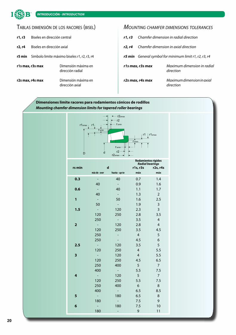
Dimensiones limite racores para rodamientos cónicos de rodillos
Mounting chamfer dimension limits for tapered roller bearings
Rodamientos rígidosRadial bearings
rs min d r1s, r3s r2s, r4s
más de - over hasta - up to máx máx
0.3 - 40 0.7 1.440 - 0.9 1.6
0.6 - 40 1.1 1.740 - 1.3 2
1 - 50 1.6 2.550 - 1.9 3
1.5 - 120 2.3 3120 250 2.8 3.5250 - 3.5 4
2 - 120 2.8 4120 250 3.5 4.5250 - 4 5250 - 4.5 6
2.5 - 120 3.5 5120 250 4 5.5
3 - 120 4 5.5120 250 4.5 6.5250 400 5 7400 - 5.5 7.5
4 - 120 5 7120 250 5.5 7.5250 400 6 8400 - 6.5 8.5
5 - 180 6.5 8180 - 7.5 9
6 - 180 7.5 10180 - 9 11
TABLAS DIMENSIÓN DE LOS RACORES (BISEL)
r1, r3 Biseles en dirección central
r2, r4 Biseles en dirección axial
r5 min
Simbolo limite máximo biseles r1, r2, r3, r4
r1s max, r3s max Dimensión máxima en dirección radial
r2s max, r4s max Dimensión máxima en dirección axial
MOUNTING CHAMFER DIMENSIONS TOLERANCES
r1, r3 Chamfer dimension in radial direction
r2, r4 Chamfer dimension in axial direction
r5 min
General symbol for minimum limit r1, r2, r3, r4
r1s max, r3s max Maximum dimension in radial direction
r2s max, r4s max Maximum dimension in axial direction

21
INTRODUCCIÓN INTRODUCTION
MATERIALES UTILIZADOS PARA LA FABRICACIÓN DE LOS RODAMIENTOS
Tanto los anillos como los elementos rotativos de los rodamientos, están sujetos a un elevado nivel de estrés sobre una superficie de contacto muy restringida; por dicho motivo,deben contar con una alta resistencia al desgaste y a la fatiga.
Están por lo tanto principalmente construidos con acero cromo de elevada calidad, de acuerdo con las normas SAE 52100-CR6 que exponemos en la siguiente tabla que indica la composición química Bajo demanda pueden ser fabricados también de acero
INOX.
MATERIAL USADO PARA LA JAULALos tipos de jaulas varían segun las condiciones de utilización.
Las más comunes están fabricadas en chapa de acero estampado. Otros tipos se fabrican con latón o, en el caso en el cual se verifique una aplicación que implique altas velocidades, con resinas poliamidicas reforzadas.
TRATAMIENTO TÉRMICOGeneralmente los rodamientos pueden soportar
temperaturas máximas de +120°C. Si este límite se supera los rodamientos deben ser sometidos a tratamientos térmicos especiales. Los rodamientos cerrados, tipo 2RS, se deberían utilizar a temperaturas máximas de +80°C. Si la temperatura supera este límite, la eficacia de los lubricantes y de las juntas se reduce mucho.
Composición química del acero para cojinetes
Chemical content of bearing steel
Estado
Country
Símbolo
SymbolC % Si Mn P S Cr Ni Mo
AlemaniaGermany
105Cr4 1.00-1.10 0.15-0.35 0.25-0.40 ≤0.030 ≤0.025 0.90-1.15 - -
AlemaniaGermany
100Cr6 0.90-1.05 0.15-0.35 0.25-0.40 ≤0.025 ≤0.025 1.40-1.65 - -
100CrMn6 0.90-1.05 0.50-0.70 1.00-1.20 ≤0.025 ≤0.020 1.40-1.65 - -
USAUSA
E51100 0.98-1.10 0.20-0.35 0.25-0.45 ≤0.025 ≤0.025 0.90-1.15 ≤0.025 ≤0.08
USAUSA
E52100 0.98-1.10 0.20-0.35 0.25-0.45 ≤0.025 ≤0.025 1.30-1.60 ≤0.025 ≤0.08
485Gr.5 0.98-1.10 0.20-0.35 1.05-1.35 ≤0.025 ≤0.025 1.90-1.40 ≤0.025 0.45-0.65
JapónJapan
SUJ 2 0.95-1.10 0.15-0.35 ≤0.50 ≤0.025 ≤0.025 1.30-1.80 ≤0.025 ≤0.08
JapónJapan
SUJ 3 0.95-1.10 0.40-0.70 0.90-1.15 ≤0.025 ≤0.025 0.90-1.20 ≤0.025 ≤0.08
MATERIALS USED DURING THE CONSTRUCTION OF BEARINGS
Both the rings and the rolling elements of the bearings, are subjected to high stress on a very small contact surface; for this reason they must have a high resistance to wear and to fatigue. On that account bearings are made of very high quality carbon chromium steel. In accordance with SAE 52100-CR6, please find belw table describing chemical composition. These bearings can be manufactured, under request, in stainless steel.
CAGE MATERIALSDifferent types of cages are determined by the operati-
ne conditions. The most common are made of pressed steel. For high speeds applications, reinforced polyamid cages are manufactured; for other employment brass cages are used.
HEAT TREATMENTBearings are usually able to stand a maximum tempera-
ture of +120°C. In the case of higher temperature, bearings with special heat treatments should be used. Sealed bearings, 2RS type, should be used at operating temperatures up to +80°C.
If the temperature is higher, the efficacy of lubricants and seals is considerably reduced.

22
INTRODUCCIÓN INTRODUCTION
LUBRICACIÓN DE LOS RODAMIENTOSLa seguridad operativa y la durabilidad nominal de servicio de
los rodamientos dependen del tipo de lubricante y del método de lubricación. La lubricación de los rodamientos tiene las siguientes finalidades: reducir, en fase de funcionamiento, el roce entre los cuerpos
envolventes, la jaula y los aros de rodadura; reducir, entre ciertos límites, el nivel de ruido de funcionamiento
de los rodamientos; garantizar a los rodamientos protección contra la corrosión.
Los lubricantes para rodamientos deben responder a los siguientes requisitos: resultar estables a nivel físico y químico; resultar libres de cuerpos extraños procedentes de los
componentes mecánicos (como abrasivos, sustancias metálicas, etc);
presentar un coeficiente mínimo de fricción; no ser corrosivos; presentar una buena capacidad lubricante.
Para los rodamientos se emplean dos categorías de lubricantes: lubricantes fluidos (aceites); lubricantes sólidos/plásticos (grasas);
Los lubricantes estándares empleados son Chevron SRI-2 o Shell Alvania2
En la elección del lubricante el coeficiente de viscosidad se deberá aumentar proporcionalmente a las dimensiones del rodamiento y a los valores de carga y de temperatura.
BEARINGS LUBRICATIONSafe operating life and long rating life of a bearing de-
pends on the type of lubricant and on the lubrication method. Bearings lubrication has the following purposes:
to reduce friction between elements, cage and receway durino operation;
to reduce, within certain limits, the noise in bearings;
to grant anticorrosive protection to bearings.Lubricants for bearings have to satisfy the following
requirements: they should have physical and chemical stability; they should be free from foreing mechanical substances
such as abrasive, metallic substances and so on;
they should have a minimal coefficient of friction; they should not be corrosive; they should dave a good lubricatign capacity.
Two categories of lubricants are used for bearing lubri-cation: fluid lubricants (oils); plastic lubricants (greases).
Bearings are supplied with Chevron SRI-2 or Shell Alvania2 grease
Concerning the choice of a lubricant, the viscosity factor must be directly and proportionally increased respect to bearing size, value of load and temperature.

23
INTRODUCCIÓN INTRODUCTION
GRASAS DISPONIBLES BAJO DEMANDA
Fabricante
Producer
Marca
Brand
Origen
Base oil
Punto de
goteo °C
Drop point °C
Consistencia
Consistency
Temperatura
se servicio °C
Operating
temperature
range °C
Aplicación
Application
Exxon
Beacon 325 Grasa sintéticaSynthetic grease 193 290 -60 ~ +120 Baja temperatura
Low temperature
Andok B MineralMineral 260 280 -40 ~ +120 Genérica
General purpose
Andok C MineralMineral ≥ 260 205 -20 ~ +120 Genérica
General purpose
Andok 260 MineralMineral 200 250 -30 ~ +150 Genérica
General purpose
Kyodo
Yushi
Multemp PS2 DiesterDiester 189 280 -50 ~ +110 Baja temperatura
Low temperature
Multemp SRL EsterEster 191 245 -40 ~ +150 Bajo nivel de ruido
Low noise
Multemp SRH EsterEster 250 201 -40 ~ +150 Baja temperatura
Low temperature
Multemp SB-M Aceite sintéticoSynthetic oil 220 260 -40 ~ +200 Alta velocidad y temperaturas
High speed and temperature
ET-K Aceite sintéticoSynthetic oil 260 300 -40 ~ +200 Alta temperatura
High temperature
Kluber
Asonic GLY32 SintéticoSynthetic 190 265-295 -50 ~ +140 Baja temperatura
Low temperature
Asonik GHY72 Ester mineralEster Mineral 250 250-280 -40 ~ +180 Alta temperatura y bajo nivel de ruido
High temperature and low noiseIsoflex Super
LDS18DiesterDiester 190 280 -60 ~ +130 Baja temperatura
Low temperatureIsoflex LDS18
Special ADiesterDiester 190 280 -60 ~ +130 Baja temperatura
Low temperatureIsoflex Topas
NB52Hidrocarburo sintéticoHydrocarbon synthetic 204 280 -60 ~ +170 Baja y alta temperatura
Low and high temperature
Barrierta L55/2 FluoradoFluorinated — 280 -35 ~ +260 Baja y alta temperatura
Low and high temperature
Barrierta TK44N2 SiliconaSilicone — — -60 ~ +230 Baja y alta temperatura
Low and high temperature
Isoflex NCA15 Ester mineralEster Mineral 180 265-295 -40 ~ +130 Alta velocidad
High speedAsonic
HQ72-102EsterEster 240 250-280 -40 ~ +180 Baja y alta temperatura y bajo nivel de ruido
Low and high temperature and low noise
Dow
Corning
Molykote 33M SiliconaSilicone 210 260 -70 ~ +180 Baja y alta temperatura
Low and high temperature
Molykote 33M SiliconaSilicone 204 260 -40 ~ +200 Alta temperatura
High temperature
Molykote 55M SiliconaSilicone — — -55 ~ +165 Bajas temperaturas
Low temperature
Shell
Alvania No.2 MineralMineral 182 272 -25 ~ +120 Genérica
General purpose
Alvania No.3 MineralMineral 183 233 -20 ~ +135 Genérica
General purpose
Alvania RA MineralMineral 183 252 -25 ~ +120 Genérica
General purpose
Alvania EP2 MineralMineral 185 276 -10 ~ +100 Genérica
General purpose
Dolium R MineralMineral 238 281 -20 ~ +140 Genérica
General purpose
Aero Shell NO.5 MineralMineral ≥ 260 282 -10 ~ +130 Genérica
General purpose
Aero Shell NO.7 MineralMineral ≥ 260 288 -70 ~ +150 Baja temperatura
Low temperature
Aero Shell RLQ2 MineralMineral 195 266 -50 ~ +150 Bajo nivel de ruido y alta velocidad
Low noise and high speed
Mobil
Oil
Mobilux2 MineralMineral 190 280 -20 ~ +120 Genérica
General purpose
Mobil 22 Mineral DiesterDiester Mineral 192 274 -50 ~ +140 Baja temperatura
Low temperature
Mobil 28 Hidrocarburo sintéticoHydrocarbon synthetic ≥ 260 280 -60 ~ +180 Baja y alta temperatura
Low and high temperature
Mobilitemp SHC22 Aceite sintéticoSynthetic oil 250 265-295 -50 ~ +180 Alta velocidad y temperatura
High speed and temperature
Mobilitemp SHC100 Aceite sintéticoSynthetic oil 250 265-295 -40 ~ +200 Alta velocidad y temperatura
High speed and temperature
Du Pont Krytox 240AC FluoradoFluorinated — 282 -35 ~ +280 Alta temperatura
High temperature
Caltex Chevron SRI-2 MineralMineral — 293 -30 ~ +175 Alta temperatura
High temperature
Hangu Hangu#2 MineralMineral — — -20 ~ +120 Genérica
General purpose
LUBRICANTS AVAILABLE UNDER REQUEST

24
INTRODUCCIÓN INTRODUCTION
PAQUETES - EMBALAJES Paquetes individuales Todos los rodamientos ISB® se pueden
suministrar en paquetes individuales, dentro de cajas de cartón, en bloques de celofán o en cajones de madera, según la dimensión del rodamiento.
Paquetes industriales. Cuando los rodamientos se emplean en grandes cantidades en las líneas de montaje pueden ser solicitados en paquetes industriales y sueltos, protegidos por hojas de nylon o tubos de plástico, en cajas de cartón, que pueden contener diferentes cantidades (incluso centenares) según las dimensiones del rodamiento.
Embalaje para el transporte. Las cajas de los rodamientos se apilan en general en pallets con flejes o dentro de grandes cajones de madera sobre pallets, para facilitar el transporte.
PACKING Single packing ISB® bearings can be supplied individually
packed, inserted in carton boxes, rolled in cellophane; or in wooden cases, depending on bearing dimensions.
Industrial packing This is the case of direct users, where bearings are requested in very big quantities to use on assembling lines. Under request they are delivered loose in a box, protected by nylon sheets or packed in plastic tubes and inserted therefore in carton boxes. These are able to contain different quantities, even hundreads, depending on bearing dimensions.
Transport packing Bearing boxes are usually piled up on bound pallets or inserted in wooden cases rested on pallets to get he transport operations easier.

25
INTRODUCCIÓN INTRODUCTION
SUFIJOS DE LOS RODAMIENTOS
Z Blindaje de metal de un lado del rodamientoZZ Blindaje de metal de ambos lados del rodamientoRS Junta de goma de un lado del rodamiento2RS Junta de goma de ambos lados del rodamientoN Ranurado en el anillo externo para anillo bloqueoNR Ranurado en el anillo externo con anillo (de bloqueo) M Jaula de latónMA Jaula de latón centrada en el anillo externoMB Jaula de latón centrada en el anillo internoTN Jaula de poliamida reforzadaP6 Tolerancia clase ISO 6P5 Tolerancia clase ISO 5P4 Tolerancia clase ISO 4C2 Juego inferior normalC3 Juego superior normalC4 Juego superior en el C3C5 Juego superior en el C4K Orificio conico
BEARINGS SUFFIX
Z Metal shield at one side of the bearingZZ Metal shields at both sides of the bearingRS Rubbing seal at one side of the bearing2RS Rubbing seals at both sides of the bearingN Snap ring groove in outer ringNR Snap ring groove in outer ring with stop ringM Machined brass cageMA Machined brass cage centred on the outer ringMB Machined brass cage centred on the inner ringTN Reinforced polyamid cageP6 Accuracy to ISO tollerance class 6P5 Accuracy to ISO tollerance class 5P4 Accuracy to ISO tollerance class 4C2 Radial clearance less than normalC3 Radial clearance greater than normalC4 Radial clearance greater than C3C5 Radial clearance greater than C4K Conical bore