Embed Size (px)
Citation preview
Rocky Mountain Slayer
Technical Manual Rev: A

Table of Contents Materials Required ..................................................................................................................... 3
Suspension Pivot Torque Guide ................................................................................................. 4
Small Parts Torque Guide .......................................................................................................... 5
Assembly Instructions ................................................................................................................ 6
1) Bearing Installation .......................................................................................................... 6
1.1 Main Pivot Bearing Installation ...................................................................................... 6
1.2 Chain Stay Bearing Installation ..................................................................................... 6
1.3 Top Link Bearing Installation ......................................................................................... 7
1.4 Shock Eyelet Bearing Installation .................................................................................. 8
2) Frame Assembly ............................................................................................................. 9
2.1 Chain Stay Installation .................................................................................................. 9
2.2 Top Link Installation .....................................................................................................10
2.3 Seat Stay Installation ...................................................................................................11
2.4 Shock Installation .........................................................................................................12
3) Plastic Component Installation .......................................................................................13
3.1 Downtube Cable Port ...................................................................................................13
3.2 Chain Guide .................................................................................................................13
3.3 Chain Stay Protector ....................................................................................................13
3.4 Seat Stay Protector ......................................................................................................13
4) Rear Axle & Rear Derailleur Hanger ...............................................................................14
5) Cable Routing.................................................................................................................15
5.1 Internal Cable Noise Damping Hose ............................................................................15
5.2 Head Tube Port Cable Routing ....................................................................................16
5.3 Frame Cable Routing ...................................................................................................16
Disassembly Instructions ..........................................................................................................17
1) PipeLock Removal .........................................................................................................17
2) Bearing Removal ............................................................................................................19

Materials Required - Rocky Mountain Slayer MY 2017 Frame
- Slayer Tool Kit
- Loctite 243 (blue)
- Grease
- Torque Wrench
o 2.5mm, 5mm, 6mm, and 8mm Hex Key Bits
- Isopropyl Alcohol
- Clean Rags
- Blind Puller (10mm OD)
- Vise with Soft Jaws

Suspension Pivot Torque Guide Note: All Torque values are +/-- 10%
Description Part # Location Tool Torque
Notes kg-cm Nm lb-in
A Shock Bolts
1807037 Top Link 5mm Hex Key
92 9 80 Loctite 243 (blue) threads, grease bolt shanks. 1807024
Front Triangle
6mm Hex Key
B PipeLock Bolt
1807039
FT-TL Pivot
5mm Hex Key
127 13 110 Grease threads.
C Bearing Preload Screw
1806087 8mm Hex Key
175 17 152 Loctite 243 (blue) threads.
D Seat Stay Pivot Screws
1807039
SS-TL Pivot 6mm Hex
Key 175 17 152
Loctite 243 (blue) threads, grease screw shank. SS-CS
Pivot
E Main Pivot Bolt
1807029 Main Pivot
6mm Hex Key
175 17 152 Loctite 243 (blue) threads, grease bolt shank.
A
B, C
D
E

Small Parts Torque Guide Note: All Torque values are +/-- 10%
Description Part # Location Tool Torque
Notes kg-cm Nm lb-in
E Counter Sunk M4x16mm Screw
1806013 Downtube Cable Port
2.5mm Hex Key
<9 <1 <8 Loctite 243 (blue). Tighten until snug.
F Rear Axle Nut 1807046 Drive-Side Dropout
6mm Hex Key
204 20 177
Left hand thread, apply Loctite 243 (blue) to male threads.
G Rear Axle 1807045
Non-Drive-Side Dropout
6mm Hex Key
104 10 90
Apply grease to axle shaft and threads. Use Stainless Steel Washer (3227006) on Non-Drive-Side.
F, G
F, G

Assembly Instructions
1) Bearing Installation
1.1 Main Pivot Bearing Installation
1) Using 6903 Bearing Press, 6900Bearing Washer, and M10 Bolt asshown, install non-drive-side Enduro6900 2RS MAX (1807042) Bearing.
2) Grease exterior of Main Pivot Spacer(1807038), slide into main pivot.
3) Using 6903 Bearing Press, 6900Bearing Washer, and M10 Bolt asshown, install drive-side Enduro 69002RS MAX (1807042) Bearing.
4) Inspect bearings for proper seatingagainst frame.
1.2 Chain Stay Bearing Installation
1) Using DR11197 Bearing Tool, installEnduro DR11197 (1807034) Bearings.
2) Inspect bearings for proper seatingagainst frame.
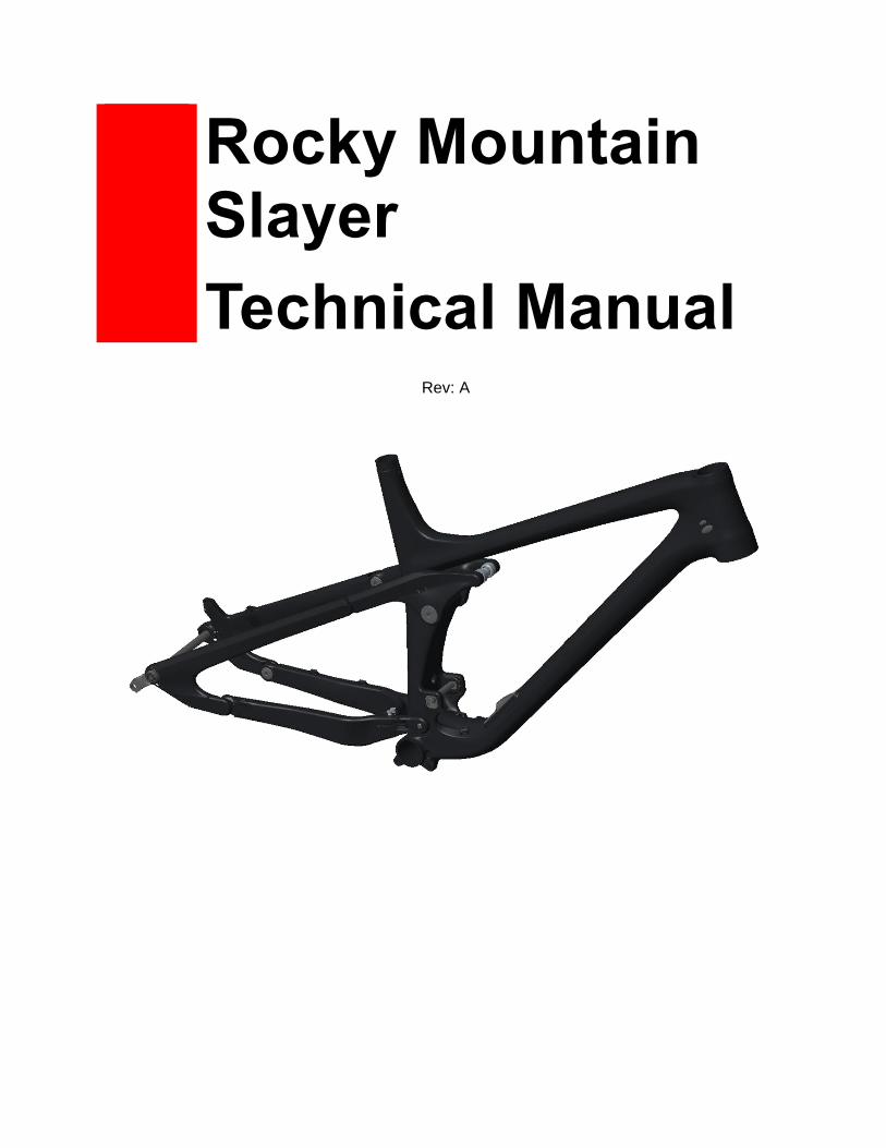
1.3 Top Link Bearing Installation
1) Using DR11197 Bearing Tool, installEnduro DR11197 (1807034) Bearings.
2) Inspect bearings for proper seatingagainst frame.
1) Using 6903 Bearing Tool, installEnduro 6903 (1807112) Bearings.
2) Inspect bearings for proper seatingagainst frame.

1.4 Shock Eyelet Bearing Installation
1) Grease EyeletBearing Sleeve(1807028).
2) Using a vise with soft jaws, pressin the Eyelet Bearing Cups(1807026) and Sleeve into theshock.
Note: Install the eyelet bearings into the link side of the shock.
3) Inspectbearings forproper seatingagainst shock.

2) Frame Assembly
2.1 Chain Stay Installation
1) Grease outside of main pivotbearing inner races, and outersurface of Main Pivot Bolt(1807029).
Apply Loctite 243 (blue) to threadson the drive-side of the chain stayyoke.
2) Slide chainstay over fronttriangle mainpivot.
3) Install Main PivotBolt.
Torque to 17 Nm.

2.2 Top Link Installation
1. Grease Top LinkPipeLock Axle (1806088& 1806089) exteriors,PipeLock Bolt (1807039)threads, and 6903Bearing Spacer(1806093) faces.
Loctite Preload Screw (18-6087) threads
2. Place greased 6903Bearing Spacer againsttop link bearings, withtheir narrow facescontacting the bearinginner races.
3. Slide top linkassembly aroundfront triangle, andinstall Drive-SidePipeLock Axle(1806089).
4. Install Non-Drive-Side PipeLock Axle(1806088) and PipeLock Bolt with BrassWasher (1807069).
Torque PipeLock Bolt to 13 Nm.
5. Install Bearing Preload Screws.
Torque Preload Screws to 17 Nm.

2.3 Seat Stay Installation
1) Apply Loctite 243(blue) to inside ofthreaded seat stayinserts.
2) Pass Rear PivotScrews (1807035)through chain staybearings, and threadinto seat stay.
Torque to 17 Nm.
3) Pass Rear PivotScrews (1807035)through top link staybearings, and threadinto seat stay.
Torque to 17 Nm.

2.4 Shock Installation
1) Grease outside of Link (1807049) and FT(1807062) Shock Bolts, Bearing Spacers(1807099), and the outside of Outer(1807003) and Inner (1807004) Ride-9Chips.
Apply Loctite 243 (blue) to M6-1.0 x 16mm (180566-016 FBY) and M6-1.0 x 12mm (180566-012 FBY) SS Screw threads.
2) Slide shock, with correct hardware(see exploded diagram) into fronttriangle, slide in FT Shock Bolt fromthe drive-side.
3) Select Ride-9 Position using the Outerand Inner Ride-9 Chips.
4) Seat bearing spacers with narrowinner faces against bearings, andslide shock into link
Pass Link Shock Bolt through Ride-9 Chips, top link, and shock from the drive-side.
5) Pass M6-1.0 x 16mm SS Screw throughM6 Counter-Sunk Washer (1807064), andthread into FT Shock Bolt.
Torque to 9 Nm.
6) Pass M6-1.0 x 16mm SS Screwthrough non-drive-side Ride-9 Chip,and thread into Link Shock Bolt.
Torque to 9 Nm.

3) Plastic Component Installation
3.1 Downtube Cable Port
1) Apply Loctite 243 (blue) to Counter Sunk(1806013) screw threads.
2) Pass (1806013) screws throughDowntube Cable Port (1097023)and thread into front triangle.
Torque to snug (<1 Nm).
3.2 Chain Guide
3.3 Chain Stay Protector
3.4 Seat Stay Protector

4) Rear Axle & Rear Derailleur Hanger
1) Apply Loctite 243 (blue) to Axle Nut(3227001) threads
Note: Axle Nut and Derailleur Hanger are left hand (reverse) threaded! Turn counter-clockwise to tighten.
2) Pass Axle Nut through seat stay,and thread into rear derailleurhanger.
Note: Select the correct rear derailleur hanger, either Shimano Direct Mount (3227002) or Standard Mount (1097132).
Torque to 20 Nm.
3) Grease rear axle (3227009) body andthreads.
4) Pass through Stainless SteelWasher (3227006), seat stay, hub,and thread into axle nut.
With hub installed, torque to 10 Nm.
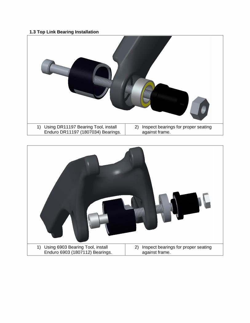
5) Cable Routing
5.1 Internal Cable Noise Damping Hose
We recommend that users install our Foam Tubes to damp cable noise within the frame.
Note: Only the one cable is shown in this image for clarity.
1) Pour isopropyl alcohol downFoam Tube to lubricatefoam tube.
Foam Tube for 4mmHousing (3337001).
Foam Tube for 5mmHousing (3337002).
2) Slide one foam tube over each internal cable,prior to routing cables through frame.
Note: The foam tubes do not fit through either thehead tube or down tube cable ports.

5.2 Head Tube Port Cable Routing
Colour Coding: Green – 6mm Hose (hydraulic line with Connectamajig or smaller) Blue – 4mm Housing (mechanical shift cable housing or smaller)
Note: We supply our bikes with rubber grommets to ensure a snug fit for cables within each port. Please see the exploded diagram to find the correct grommets for your bike.
5.3 Frame Cable Routing
Colour Coding: Green – Brake Hose Pink – Internal Dropper Post Hose
Blue – Rear Derailleur Cable

Disassembly Instructions
1) PipeLock Removal
1. Remove all Bearing Preload Screws(1806087).
2. Remove PipeLock Bolt (1807039) andBrass Washer (1807069).

3. Thread M6 PipeLock Removal Toolinto threaded, Drive-Side PipeLockAxle (1806089) from non-drive-side.
4. Using a hammer, hit the M6 PipeLockRemoval Tool to remove the Drive-SidePipeLock Axle.
5. Slide M6 PipeLock Removal Tool intounthreaded, Non-Drive-Side PipeLockAxle (1806088) from drive-side.
6. Using a hammer, hit the M6 PipeLockRemoval Tool to remove the Non-Drive-Side PipeLock Axle.

2) Bearing RemovalNote: This process is the same for all Pivots except the Main Pivot, which requires a blind
puller.
1. Seat appropriateBearing Tool Presswith wide faceagainst bearinginner race.
2. Pass bolt throughBearing Tool Press andset Bearing Cup againstframe component withthe open side towardsthe bearing.
3. Tighten nut and bolt topress bearing out offrame component.
TL-FT Bearing Removal (6903 Tool) TL-SS Bearing Removal (DR11197 Tool)
Chain Stay Bearing Removal (DR11197 Tool)