Embed Size (px)
Citation preview

Rockwell Automation Library of Process Objects: Boolean Logic with Snapshot (P_Logic)Version 3.5
Reference Manual
IMPORTANT This manual applies to the Rockwell Automation Library of Process Objects version 3.5 or earlier.For Rockwell Automation Library of Process Objects version 4.0 or later, use the following manuals:• PROCES-RM013 contains logic instructions• PROCES-RM014 contains display elements

Important User Information
Read this document and the documents listed in the additional resources section about installation, configuration, and operation of this equipment before you install, configure, operate, or maintain this product. Users are required to familiarize themselves with installation and wiring instructions in addition to requirements of all applicable codes, laws, and standards.
Activities including installation, adjustments, putting into service, use, assembly, disassembly, and maintenance are required to be carried out by suitably trained personnel in accordance with applicable code of practice.
If this equipment is used in a manner not specified by the manufacturer, the protection provided by the equipment may be impaired.
In no event will Rockwell Automation, Inc. be responsible or liable for indirect or consequential damages resulting from the use or application of this equipment.
The examples and diagrams in this manual are included solely for illustrative purposes. Because of the many variables and requirements associated with any particular installation, Rockwell Automation, Inc. cannot assume responsibility or liability for actual use based on the examples and diagrams.
No patent liability is assumed by Rockwell Automation, Inc. with respect to use of information, circuits, equipment, or software described in this manual.
Reproduction of the contents of this manual, in whole or in part, without written permission of Rockwell Automation, Inc., is prohibited.
Throughout this manual, when necessary, we use notes to make you aware of safety considerations.
Labels may also be on or inside the equipment to provide specific precautions.
Allen-Bradley, Rockwell Software, and Rockwell Automation are trademarks of Rockwell Automation, Inc.
Trademarks not belonging to Rockwell Automation are property of their respective companies.
WARNING: Identifies information about practices or circumstances that can cause an explosion in a hazardous environment, which may lead to personal injury or death, property damage, or economic loss.
ATTENTION: Identifies information about practices or circumstances that can lead to personal injury or death, property damage, or economic loss. Attentions help you identify a hazard, avoid a hazard, and recognize the consequence.
IMPORTANT Identifies information that is critical for successful application and understanding of the product.
SHOCK HAZARD: Labels may be on or inside the equipment, for example, a drive or motor, to alert people that dangerous voltage may be present.
BURN HAZARD: Labels may be on or inside the equipment, for example, a drive or motor, to alert people that surfaces may reach dangerous temperatures.
ARC FLASH HAZARD: Labels may be on or inside the equipment, for example, a motor control center, to alert people to potential Arc Flash. Arc Flash will cause severe injury or death. Wear proper Personal Protective Equipment (PPE). Follow ALL Regulatory requirements for safe work practices and for Personal Protective Equipment (PPE).

Table of ContentsPreface Software Compatibility and Content Revision. . . . . . . . . . . . . . . . . . . . 5
Additional Resources . . . . . . . . . . . . . . . . . . . . . . . . . . . . . . . . . . . . . . . . . . . 6Boolean Logic with Snapshot (P_Logic)
Guidelines . . . . . . . . . . . . . . . . . . . . . . . . . . . . . . . . . . . . . . . . . . . . . . . . . . . . . 7Functional Description . . . . . . . . . . . . . . . . . . . . . . . . . . . . . . . . . . . . . . . . . 8Required Files. . . . . . . . . . . . . . . . . . . . . . . . . . . . . . . . . . . . . . . . . . . . . . . . . 10
Controller File . . . . . . . . . . . . . . . . . . . . . . . . . . . . . . . . . . . . . . . . . . . . 10Visualization Files . . . . . . . . . . . . . . . . . . . . . . . . . . . . . . . . . . . . . . . . . 10
Controller Code . . . . . . . . . . . . . . . . . . . . . . . . . . . . . . . . . . . . . . . . . . . . . . 12Boolean Logic Input Structure . . . . . . . . . . . . . . . . . . . . . . . . . . . . . . 12Boolean Logic Output Structure . . . . . . . . . . . . . . . . . . . . . . . . . . . . 13Boolean Logic Local Configuration Tags . . . . . . . . . . . . . . . . . . . . 15
Operations . . . . . . . . . . . . . . . . . . . . . . . . . . . . . . . . . . . . . . . . . . . . . . . . . . . 17Configuring the Logic in a P_Logic Instance . . . . . . . . . . . . . . . . . 17Rules for Set-Reset Gate. . . . . . . . . . . . . . . . . . . . . . . . . . . . . . . . . . . . 17Operating Modes . . . . . . . . . . . . . . . . . . . . . . . . . . . . . . . . . . . . . . . . . . 17Alarms. . . . . . . . . . . . . . . . . . . . . . . . . . . . . . . . . . . . . . . . . . . . . . . . . . . . 17Simulation . . . . . . . . . . . . . . . . . . . . . . . . . . . . . . . . . . . . . . . . . . . . . . . . 18Execution . . . . . . . . . . . . . . . . . . . . . . . . . . . . . . . . . . . . . . . . . . . . . . . . . 18
Programming Example. . . . . . . . . . . . . . . . . . . . . . . . . . . . . . . . . . . . . . . . . 18Display Elements . . . . . . . . . . . . . . . . . . . . . . . . . . . . . . . . . . . . . . . . . . . . . . 20
Status/Quality Indicators . . . . . . . . . . . . . . . . . . . . . . . . . . . . . . . . . . 21Using Display Elements . . . . . . . . . . . . . . . . . . . . . . . . . . . . . . . . . . . . 22
Faceplate . . . . . . . . . . . . . . . . . . . . . . . . . . . . . . . . . . . . . . . . . . . . . . . . . . . . . 23Operator Tab . . . . . . . . . . . . . . . . . . . . . . . . . . . . . . . . . . . . . . . . . . . . . 24View Snapshot Tab . . . . . . . . . . . . . . . . . . . . . . . . . . . . . . . . . . . . . . . . 25Engineering Tab. . . . . . . . . . . . . . . . . . . . . . . . . . . . . . . . . . . . . . . . . . . 26Gate Configuration Display . . . . . . . . . . . . . . . . . . . . . . . . . . . . . . . . 29Boolean Logic with Snapshot Faceplate Help . . . . . . . . . . . . . . . . 30
Rockwell Automation Publication SYSLIB-RM027E-EN-P - February 2017 3

Table of Contents
Notes:
4 Rockwell Automation Publication SYSLIB-RM027E-EN-P - February 2017

Preface
This manual contains new and updated information. Changes throughout this revision are marked by change bars, as shown to the right of this paragraph.
Software Compatibility and Content Revision
For the latest compatible software information and to download the Rockwell Automation® Library of Process Objects, see the Product Compatibility and Download Center at http://www.rockwellautomation.com/rockwellautomation/support/pcdc.page.
For general library considerations, see Rockwell Automation Library of Process Objects, publication PROCES-RM002.
Table 1 - Summary of Changes
Topic Page
Local Configuration Tags - Navigation Tag 16
Rockwell Automation Publication SYSLIB-RM027E-EN-P - February 2017 5

Preface
Additional Resources These documents contain additional information concerning related products from Rockwell Automation.
You can view or download publications athttp:/www.rockwellautomation.com/literature/. To order paper copies of technical documentation, contact your local Allen-Bradley® distributor or Rockwell Automation sales representative.
Resource Description
PlantPAx® Distributed Control System Selection Guide, publication PROCES-SG001
Provides information for assisting with the equipment procurement for your PlantPAx system.
PlantPAx Distributed Control System Reference Manual, publication PROCES-RM001
Provides characterized recommendations for implementing your PlantPAx system.
Rockwell Automation Library of Process Objects,publication PROCES-RM002
Provides general considerations for the PlantPAx system library of process objects.
FactoryTalk® View Machine Edition User Manual,publication VIEWME-UM004
Provides details on how to use this software package for creating an automation application.
FactoryTalk View SE Edition User Manual,publication VIEWSE-UM006
Provides details on how to use this software package for developing and running human-machine interface (HMI) applications that can involve multiple users and servers, distributed over a network.
Logix5000™ Controllers Add-On Instructions Programming Manual, publication 1756-PM010
Provides information for designing, configuring, and programming Add-On Instructions.
Rockwell Automation Library of Process Objects: Common Alarm Block (P_Alarm) Reference Manual, publication SYSLIB-RM002
Details how to monitor an input condition to raise an alarm. Information includes acknowledging, resetting, inhibiting, and disabling an alarm. Generally the P_Alarm faceplate is accessible from the Alarms tab.
6 Rockwell Automation Publication SYSLIB-RM027E-EN-P - February 2017

Boolean Logic with Snapshot (P_Logic)
The P_Logic (Boolean Logic with Snapshot) Add-On Instruction executes up to eight gates of configurable Boolean logic. Gate types available include AND, OR, XOR (Exclusive-OR), Set/Reset, Select, and Majority. Each gate provides up to four input conditions that are individually invertible. (The P_Logic instruction does not need a NOT gate.)
The P_Logic Add-On Instruction also provides a snapshot capability, enabling it to record its current state (with an optional time stamp) upon change in output state, on Operator or Program command, or based on a logic loopback input.
Guidelines Use this instruction in these situations:• You want to implement an Interlock or Permissive condition that is more
complicated than the simple OR-ing or AND-ing provided by the P_Intlk (Interlocks) or P_Perm (Permissives) Add-On Instructions.
• You want to implement some Boolean (combination) logic that can be reconfigured from the HMI online, or which requires the snapshot capability for saving a copy of the logic state with a timestamp.
Global Object
Add-On Instruction Faceplate
Rockwell Automation Publication SYSLIB-RM027E-EN-P - February 2017 7

Boolean Logic with Snapshot (P_Logic)
• You have more than the 16 interlock conditions or permissive conditions provided by the P_Intlk and P_Perm Add-On Instructions, but some of the conditions can be grouped together under one identification. For example, all of the bearing overtemperature signals for a pump and motor (Pump Inboard Bearing, Pump Outboard Bearing, Motor Inboard Bearing, and Motor Outboard Bearing) can be ORed together in a P_Logic instruction and the result presented to a P_Intlk instruction as a single ‘Bearing Overtemp’ condition.
Do not use this instruction in these situations:• You are implementing simple interlocks and permissives that can be
handled by the P_Intlk and P_Perm instructions directly. These instructions can permit operation or trip operation on either the low- or high-state of a condition (configurable inverting).
• You require logic that is beyond the P_Logic Add-On Instruction capabilities or which is extremely time critical. The P_Logic instruction provides only eight inputs, eight gates, and one output with on-delay and off-delay timing, and it is implemented with table-driven code. Use hard-coded logic in native controller languages instead. The native programming languages are faster and provide functionality beyond what the P_Logic instruction can do.
Functional Description The diagram shows the functional characteristics of the P_LogicAdd-On Instruction. Boolean Logic descriptions are in the Help fileon page 30.
8 Rockwell Automation Publication SYSLIB-RM027E-EN-P - February 2017

Boolean Logic with Snapshot (P_Logic)
The Boolean Logic Add-On Instruction provides the following capabilities:• Provides up to eight Boolean inputs and eight logic gates.• Each gate has four inputs. Each input can be enabled or disabled. Each gate
input can be normal or inverted. Each enabled gate input can be linked to a source, which is an instruction input or the result of a preceding gate.
• Each of the eight gates can be configured in one of the following ways:– Logical AND: The gate's output is true if all of the enabled gate inputs
(after configured inversions) are true. An AND gate can have 1…4 inputs enabled.
– Logical OR: The gate's output is true if any of the enabled gate inputs (after configured inversions) are true. An OR gate can have1…4 inputs enabled.
– Logical XOR (Exclusive OR): The gate's output is true if an odd number of the enabled gate inputs (after configured inversions) are true. An XOR gate can have 1…4 inputs enabled.
– Set-Reset: The gate's output is set true if one of its Set inputs is true, and is cleared to false if one of its Reset inputs is true. The gate's four inputs are:
Input 1: SET (dominant)Input 2: RESET (dominant)Input 3: SETInput 4: RESET
See page 17 for Set-Reset rules.– Select: If input 3 is false, the state of input 1 is passed to the gate output.
If input 3 is true, the state of input 2 is passed to the gate output. A Select gate must have input 3 enabled and either or both of inputs 1 and 2 enabled.
– Majority (labeled ‘MooN’ for ‘M out of N’): The gate’s output is set true if a majority of its inputs (after configured inversions) are true (2 out of 2, 2 out of 3, or 3 out of 4). A Majority gate can have 2…4 inputs enabled.
• Provides configurable on-delay time and off-delay time for theinstruction's output.
• Provides a snapshot capability, that captures the state of the instruction (all input states, gate states, and output state) for use later (until reset). The snapshot capability can be used to capture the state of the logic at the time that it tripped or shut down equipment, even if the logic states change after the shutdown. The snapshot is optionally timestamped from the controller clock (year, month, day, hour, minute, second, microsecond).
Rockwell Automation Publication SYSLIB-RM027E-EN-P - February 2017 9

Boolean Logic with Snapshot (P_Logic)
• Provides options to enable the following snapshot trigger conditions:– Capture snapshot on Operator Command (OCmd_Snap).– Capture snapshot on Program Command (PCmd_Snap).– Capture snapshot when the output transitions from 0 to 1.– Capture snapshot when the output transitions from 1 to 0.– Capture snapshot of previous scan's state when a loopback input
becomes true. This last capability enables the snapshot to be captured in a case where the P_Logic output condition was the first-out condition in a downstream P_Intlk block. The first-out indication from the P_Intlk instruction can be looped back to the P_Logic instruction's Inp_Hold input to hold the last-scan state in the snapshot (including last scan's time stamp).
Required Files Add-On Instructions are reusable code objects that contain encapsulated logic that can streamline implementing your system. This lets you create your own instruction set for programming logic as a supplement to the instruction set provided natively in the ControlLogix® firmware. An Add-On Instruction is defined once in each controller project, and can be instantiated multiple times in your application code as needed.
Controller File
The P_Logic_3_5-00_AOI.L5X Add-On Instruction must be imported into the controller project to be able to be used in the controller configuration. The service release number (boldfaced) can change as service revisions are created.
Visualization Files
This Add-On Instruction has associated visualization files that provide a common user interface. These files can be downloaded from the Product Compatibility and Download Center at http://www.rockwellautomation.com/rockwellautomation/support/pcdc.page.
IMPORTANT The visualization file dependencies require Process Library content imports to
occur in a specific order as reflected in the following tables:
• Images
• Global Objects
• Standard Displays
• HMI Tags
• Macros
10 Rockwell Automation Publication SYSLIB-RM027E-EN-P - February 2017
Boolean Logic with Snapshot (P_Logic)
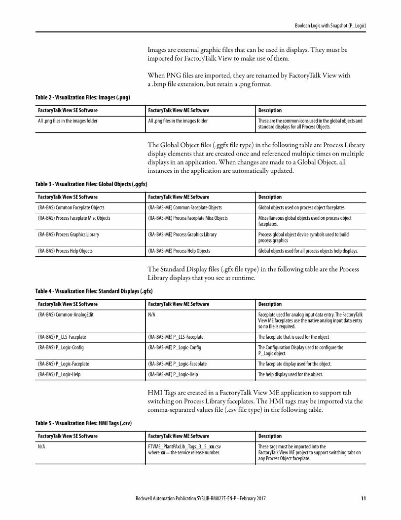
Images are external graphic files that can be used in displays. They must be imported for FactoryTalk View to make use of them.
When PNG files are imported, they are renamed by FactoryTalk View with a .bmp file extension, but retain a .png format.
The Global Object files (.ggfx file type) in the following table are Process Library display elements that are created once and referenced multiple times on multiple displays in an application. When changes are made to a Global Object, all instances in the application are automatically updated.
The Standard Display files (.gfx file type) in the following table are the Process Library displays that you see at runtime.
HMI Tags are created in a FactoryTalk View ME application to support tab switching on Process Library faceplates. The HMI tags may be imported via the comma-separated values file (.csv file type) in the following table.
Table 2 - Visualization Files: Images (.png)
FactoryTalk View SE Software FactoryTalk View ME Software Description
All .png files in the images folder All .png files in the images folder These are the common icons used in the global objects and standard displays for all Process Objects.
Table 3 - Visualization Files: Global Objects (.ggfx)
FactoryTalk View SE Software FactoryTalk View ME Software Description
(RA-BAS) Common Faceplate Objects (RA-BAS-ME) Common Faceplate Objects Global objects used on process object faceplates.
(RA-BAS) Process Faceplate Misc Objects (RA-BAS-ME) Process Faceplate Misc Objects Miscellaneous global objects used on process object faceplates.
(RA-BAS) Process Graphics Library (RA-BAS-ME) Process Graphics Library Process global object device symbols used to build process graphics
(RA-BAS) Process Help Objects (RA-BAS-ME) Process Help Objects Global objects used for all process objects help displays.
Table 4 - Visualization Files: Standard Displays (.gfx)
FactoryTalk View SE Software FactoryTalk View ME Software Description
(RA-BAS) Common-AnalogEdit N/A Faceplate used for analog input data entry. The FactoryTalk View ME faceplates use the native analog input data entry so no file is required.
(RA-BAS) P_LLS-Faceplate (RA-BAS-ME) P_LLS-Faceplate The faceplate that is used for the object
(RA-BAS) P_Logic-Config (RA-BAS-ME) P_Logic-Config The Configuration Display used to configure the P_Logic object.
(RA-BAS) P_Logic-Faceplate (RA-BAS-ME) P_Logic-Faceplate The faceplate display used for the object.
(RA-BAS) P_Logic-Help (RA-BAS-ME) P_Logic-Help The help display used for the object.
Table 5 - Visualization Files: HMI Tags (.csv)
FactoryTalk View SE Software FactoryTalk View ME Software Description
N/A FTVME_PlantPAxLib_Tags_3_5_xx.csvwhere xx = the service release number.
These tags must be imported into theFactoryTalk View ME project to support switching tabs on any Process Object faceplate.
Rockwell Automation Publication SYSLIB-RM027E-EN-P - February 2017 11

Boolean Logic with Snapshot (P_Logic)
In a FactoryTalk View SE application, a macro is a series of commands stored in a text file. In FactoryTalk View ME application, a macro is a list of tag assignments stored in a text file. The following table lists the Macros (.mcr file type) used by the Process Library.
Controller Code This section describes the parameter references for this Add-On Instruction.
Boolean Logic Input Structure
Input parameters include the following:• Input data elements (Inp_) are typically used to connect field inputs from
I/O modules or signals from other objects.• Configuration data elements (Cfg_) are used to set configurable
capabilities and features of the instruction, and to request specific actions while the instruction is in Program mode.
• Command data elements (PCmd_, OCmd_) are used by program logic, operators, and maintenance personnel to request instruction actions.
Table 6 - Visualization Files: Macros (.mcr file)
FactoryTalk View SE Software FactoryTalk View ME Software Description
NavToObject N/A This macro must be imported into the FactoryTalk View SE project to support faceplate-to-faceplate navigation by name.
Table 7 - P_Logic Input Parameters
Input Parameter Data Type
Alias For Default Description
EnableIn BOOL 1 Ladder Diagram:If the rung-in condition is true, the instruction’s Logic routine executes. If the rung-in condition is false, the instruction’s EnableInFalse routine executes.
Function Block Diagram:If true, or not connected, the instruction’s Logic routine executes. If the parameter is exposed as a pin and wired, and the pin is false, the instruction’s EnableInFalse routine executes.
Structured Text:No effect. The instruction’s Logic routine executes.
Inp_0…Inp_7 BOOL Wrk_Src.0…Wrk_Src.7 0 Logic Input 0…7.
Inp_Hold BOOL 0 1 = Hold previous state in Snapshot.
0 = Pass live states to Snapshot.
Inp_Reset BOOL 0 Input parameter used to programmatically reset alarms. When set to 1, all alarms requiring reset are reset.
Cfg_UseInpHold BOOL 0 1 = Use Inp_Hold to capture Snapshot.
0 = Use Cmds or Output transition to capture Snapshot.
Cfg_UsePCmd BOOL 1 1 = Enable Snapshot on PCmd_Snap 0 --> 1 (edge).
Cfg_UseOCmd BOOL 1 1 = Enable Snapshot on OCmd_Snap 0 --> 1 (edge).
Cfg_UseOut01 BOOL 1 1 = Enable Snapshot on Output 0 --> 1 (rising edge).
12 Rockwell Automation Publication SYSLIB-RM027E-EN-P - February 2017

Boolean Logic with Snapshot (P_Logic)
Boolean Logic Output Structure
Output parameters include the following:• Output data elements (Out_) are the primary outputs of the instruction,
typically used by hardware output modules; however, they can be used by other application logic.
• Value data elements (Val_) are numeric outputs of the instruction for use by the HMI. Values can also be used by other application logic or software packages.
• Status data elements (Sts_) are bit outputs of the instruction for use by the HMI. Status bits can also be used by other application logic.
• Error data elements (Err_) are bit outputs of the instruction used to identify the reason for configuration errors.
• Ready data elements (Rdy_) are bit outputs of the instruction used by the HMI to enable or disable Command buttons and setting entry fields.
Cfg_UseOut10 BOOL 0 1 = Enable Snapshot on Output 1 --> 0 (falling edge).
Cfg_TSonSnap BOOL 0 1 = Generate a TimeStamp when Snapshot occurs
Cfg_SnapOver BOOL 0 1 = New Snapshot overwrites without reset.
0 = Save first Snapshot until reset.
Cfg_OnDelay DINT 0 Output ON delay time (seconds).
Cfg_OffDelay DINT 0 Output OFF delay time (seconds).
PCmd_Snap BOOL 0 • Set PCmd_Snap to 1 to capture input, gate states in Snapshot
• This parameter resets automatically.
PCmd_Reset BOOL 0 • Set PCmd_Reset to 1 to reset (re-arm) snapshot latch
• This parameter resets automatically
OCmd_Snap BOOL 0 Operator command to capture Input, Gate states in Snapshot.
OCmd_Reset BOOL 0 Operator command to Reset (re-arm) Snapshot Latch.
Table 7 - P_Logic Input Parameters
Input Parameter Data Type
Alias For Default Description
Table 8 - P_Logic Output Parameters
Output Parameter Data Type Description
EnableOut BOOL Enable Output: The EnableOut signal is not manipulated by this instruction. Its output state always reflects EnableIn input state.
Out_Live BOOL Condition of Logic Output (result) after delay.
Out_Snap BOOL Condition of Logic Output (result) when at Snapshot.
Val_DelayPctLive DINT Output OnDelay or OffDelay percent complete: live.
Val_DelayPctSnap DINT Output OnDelay or OffDelay percent complete: Snapshot.
Val_SnapInit DINT Snapshot Initiator:
1= OCmd
2 = PCmd
3 = Out 0-->1
4 = Out 1-->0
5 = Inp_Hold
Rockwell Automation Publication SYSLIB-RM027E-EN-P - February 2017 13

Boolean Logic with Snapshot (P_Logic)
Sts_Snapped BOOL 1 = Snapshot has been triggered.
0 = Snapshot showing live states.
Sts_InpLive SINT Live Input Status bits: (bit# = input#).
Sts_GateLive SINT Live Gate Result Status bits: (bit# = gate#).
Sts_InpSnap SINT Snapshot of Input Status bits: (bit# = input#).
Sts_GateSnap SINT Snapshot of Gate Result Status bits: (bit# = gate#).
Sts_GateSrc1Live SINT Live wire state for Source 1…4 of each gate (bit# = gate#).
Sts_GateSrc2Live
Sts_GateSrc3Live
Sts_GateSrc4Live
Sts_GateSrc1Snap SINT Snapshot of wire state for Source 1…4 of each gate (bit# = gate#).
Sts_GateSrc2Snap
Sts_GateSrc3Snap
Sts_GateSrc4Snap
Sts_OutInvLive BOOL Output after inverter but before TON/TOF timers.
Sts_OutInvSnap BOOL Snapshot of Output after inverter but before TON/TOF.
Sts_Err BOOL 1 = Error in configuration: see detail bits for reason.
Err_GateFunc SINT 1 = Error in each Gate's Function Code (use 0…6).
Err_GateSrcPtr SINT 1 = Error in each Gate's Source Pointer (use 0…15).
Err_GateSrcMask SINT 1 = Error in each Gate's Mask (source used) configuration (qty, choice).
Err_OutSrcPtr BOOL 1 = Error in Output's Source Pointer (use 0…15).
Err_Timer BOOL 1 = Error in Output's On Delay or Off Delay Preset (use 0…2,147,483).
Rdy_Snap BOOL 1 = Ready to receive OCmd_Snap (enables button).
Rdy_Reset BOOL 1 = Ready to receive OCmd_Reset (enables button).
P_Logic BOOL Unique Parameter Name for auto-discovery.
Table 8 - P_Logic Output Parameters
Output Parameter Data Type Description
14 Rockwell Automation Publication SYSLIB-RM027E-EN-P - February 2017

Boolean Logic with Snapshot (P_Logic)
Boolean Logic Local Configuration Tags
Configuration parameters that are array, string, or structure data types cannot be configured as parameters for Add-On Instructions. Configuration parameters of these types appear as local tags in the Add-On Instruction. Local tags can be configured through the HMI faceplates or in Studio 5000 Logix Designer® application by opening the Instruction Logic of the Add-On Instruction instance and then opening the Data Monitor on a local tag. These parameters cannot be modified by using controller logic or Logix Designer application export/import functionality.
Table 9 - Local Configuration Tags
Configuration Parameter
Data Type Default Description
Cfg_0StText STRING_8 'OK' Text to display in Out = 0 State
Cfg_1StText STRING_8 'TRIPPED' Text to display in Out = 1 State
Cfg_Desc STRING_40 'Configurable Boolean Logic Block'
Description for display on HMI. This string is shown in the title bar of the faceplate.
Cfg_GateFunc
Cfg_GateFunc[0]
Cfg_GateFunc[1]
Cfg_GateFunc[2]
Cfg_GateFunc[3]
Cfg_GateFunc[4]
Cfg_GateFunc[5]
Cfg_GateFunc[6]
Cfg_GateFunc[7]
DINT[8]
0
0
0
0
0
0
0
0
Function code for gate M:
0 = Gate not used
1 = AND
2 = OR
3 = XOR
4 = M out of N (majority gate)
5 = Set-Reset (latch)
6 = Select (switch gate)
Cfg_GateSrc1Inv SINT 2#0000_0000 Gate M Source #1 is Inverted (M by bit) (1 = invert)
Cfg_GateSrc1Mask SINT 2#0000_0000 Gate M Source #1 is Used (M by bit) (1 = used)
Cfg_GateSrc1Ptr
Cfg_GateSrc1Ptr[0]
Cfg_GateSrc1Ptr[1]
Cfg_GateSrc1Ptr[2]
Cfg_GateSrc1Ptr[3]
Cfg_GateSrc1Ptr[4]
Cfg_GateSrc1Ptr[5]
Cfg_GateSrc1Ptr[6]
Cfg_GateSrc1Ptr[7]
DINT[8] {...} Pointer to Gate M Source #1:
0…7 = inputs
8…15 = gate outputs
Cfg_GateSrc2Inv SINT 2#0000_0000 Gate M Source #2 is Inverted (M by bit) (1 = invert)
Cfg_GateSrc2Mask SINT 2#0000_0000 Gate M Source #2 is Used (M by bit) (1 = used)
Cfg_GateSrc2Ptr
Cfg_GateSrc2Ptr[0]
Cfg_GateSrc2Ptr[1]
Cfg_GateSrc2Ptr[2]
Cfg_GateSrc2Ptr[3]
Cfg_GateSrc2Ptr[4]
Cfg_GateSrc2Ptr[5]
Cfg_GateSrc2Ptr[6]
Cfg_GateSrc2Ptr[7]
DINT[8] {...} Pointer to Gate M Source #2:
0…7 = inputs
8…15 = gate outputs)
Cfg_GateSrc3Inv SINT 2#0000_0000 Gate M Source #3 is Inverted (M by bit) (1 = invert).
Cfg_GateSrc3Mask SINT 2#0000_0000 Gate M Source #3 is Used (M by bit) (1 = used).
Rockwell Automation Publication SYSLIB-RM027E-EN-P - February 2017 15

Boolean Logic with Snapshot (P_Logic)
Cfg_GateSrc3Ptr
Cfg_GateSrc3Ptr[0]
Cfg_GateSrc3Ptr[1]
Cfg_GateSrc3Ptr[2]
Cfg_GateSrc3Ptr[3]
Cfg_GateSrc3Ptr[4]
Cfg_GateSrc3Ptr[5]
Cfg_GateSrc3Ptr[6]
Cfg_GateSrc3Ptr[7]
DINT[8] {...} Pointer to Gate M Source #3:
0…7 = inputs
8…15 = gate outputs
Cfg_GateSrc4Inv SINT 2#0000_0000 Gate M Source #4 is Inverted (M by bit) (1 = invert).
Cfg_GateSrc4Mask SINT 2#0000_0000 Gate M Source #4 is Used (M by bit) (1 = used).
Cfg_GateSrc4Ptr
Cfg_GateSrc4Ptr[0]
Cfg_GateSrc4Ptr[1]
Cfg_GateSrc4Ptr[2]
Cfg_GateSrc4Ptr[3]
Cfg_GateSrc4Ptr[4]
Cfg_GateSrc4Ptr[5]
Cfg_GateSrc4Ptr[6]
Cfg_GateSrc4Ptr[7]
DINT[8] {...}
0
Pointer to Gate M Source #4:
0…7 = inputs
8…15 = gate outputs)
Cfg_HasNav SINT 2#0000_0000 Set bits indicate which navigation buttons are enabled.
Cfg_InpTxt
Cfg_InpTxt[0]
Cfg_InpTxt[1]
Cfg_InpTxt[2]
Cfg_InpTxt[3]
Cfg_InpTxt[4]
Cfg_InpTxt[5]
Cfg_InpTxt[6]
Cfg_InpTxt[7]
STRING_20[8] {...} Short HMI description of each Input.
Cfg_Label STRING_20 'Configurable Logic' Label for graphic symbol displayed on HMI. This string appears on the graphic symbol.
Cfg_NavTag
Cfg_NavTag[0]
Cfg_NavTag[1]
Cfg_NavTag[2]
Cfg_NavTag[3]
Cfg_NavTag[4]
Cfg_NavTag[5]
Cfg_NavTag[6]
Cfg_NavTag[7]
STRING_NavTag
' '
' '
' '
' '
' '
' '
' '
' '
Tag names for destinations of navigation buttons.
IMPORTANT: This tag does not work in FactoryTalk ME Software.
Cfg_OutSrcInv BOOL 0 Out Source (before Min Duration Timer) is Inverted (1=invert).
Cfg_OutSrcPtr DINT 0 Source bit for Output (0…7 = inputs, 8…15 = gates).
Cfg_Tag STRING_20 'P_Logic' Description for display on HMI. This string is shown in the title bar of the faceplate.
Table 9 - Local Configuration Tags
Configuration Parameter
Data Type Default Description
16 Rockwell Automation Publication SYSLIB-RM027E-EN-P - February 2017

Boolean Logic with Snapshot (P_Logic)
Operations This section describes the primary operations for the P_Logic Add-On Instruction.
Configuring the Logic in a P_Logic Instance
A P_Logic instruction instance can be configured from the Logix Designer application tag monitor, but it’s much easier to configure the logic from the HMI.
Rules for Set-Reset Gate
The following rules apply for a Set-Reset gate:• The dominant inputs (1 and 2) take precedence over the non-dominant
(3 and 4) inputs in a Set-Reset Gate.• If Input 1 is true and Input 2 is false, the gate’s output is Set to true.• If Input 1 is false and Input 2 is true, the gate’s output is Reset to false.• If both Input 1 and Input 2 are true, the gate’s output is not changed.• If both Input 1 and Input 2 are false, Inputs 3 and 4 determine the output:
– If Input 3 is true and Input 4 is false, the gate’s output is Set to true.– If Input 3 is false and Input 4 is true, the gate’s output is Reset to false.– If both Input 3 and Input 4 are true, the gate’s output is not changed.– If both Input 3 and Input 4 are false, the gate’s output is not changed.
• A Set-Reset gate must have at least one set input (either dominant ornon-dominant) and one reset input (either dominant or non-dominant) enabled.
Operating Modes
The P_Logic Add-On Instruction has no modes and does not use the P_Mode Add-On Instruction. The Operator and Program snapshot commands, if enabled, and reset commands are accepted at any time.
Alarms
The P_Logic Add-On Instruction does not provide any alarms. If an alarm is required, use P_Din or use the interlock alarm of the device, such as P_Motor.
One of the following applies:• The inputs to a P_Logic instruction often come from status pins of P_Din
(Discrete Input) or P_AIn (Analog Input) instructions that provide alarms for these input conditions (for example, TargetDisagree, High, Low, High-High, Low-Low).
Rockwell Automation Publication SYSLIB-RM027E-EN-P - February 2017 17

Boolean Logic with Snapshot (P_Logic)
• The output of a P_Logic instruction is typically used as an interlock condition, and the interlocked device typically provides an‘Interlock Trip’ alarm.
• If an alarm is required for one of the P_Logic instruction's inputs or outputs, a P_Alarm instruction can be added to the application logic containing the P_Logic instance.
Simulation
The Boolean Logic Add-On Instruction does not have a Simulation capability.
Execution
The following table explains the handling of instruction execution conditions.
Refer to the Logix5000 Controllers Add-On Instructions Programming Manual, publication 1756-PM010, for more information.
Programming Example This example uses the P_Logic instruction to perform advanced interlocking logic that is based on the winding temperatures of a motor. P_Logic is easier to configure through the faceplate, but this example walks through the parameter settings to fully illustrate the example.
In this example, there is a motor with three RTDs measuring temperature of the windings. To prevent damage to the windings, the motor must be interlocked if any of the three windings are above the high-high temperature limit, or if the majority of the windings are above the high temperature limit. P_Logic is being used to perform this function. The output of this logic feeds the interlock of the motor elsewhere in logic.
Condition Description
Prescan Resets the output on-delay and off-delay timers; clears the snapshot time stamp and data; clears any commands received while controller was in Program mode.
EnableIn False Clears output to false (off) and resets the output on-delay and off-delay timers.
Postscan No SFC Postscan logic is provided.
18 Rockwell Automation Publication SYSLIB-RM027E-EN-P - February 2017

Boolean Logic with Snapshot (P_Logic)
The input parameters (Inp_0, Inp_1, Inp_2, Inp_3, Inp_4, Inp_5) are connected to the status outputs of the three winding temperature inputs. Three of the eight gates (0…7) in P_Logic are used in this example (1, 5, 6). Gate 1 is the OR of the three high-high status bits. Gate 5 checks if the majority of the high status bits are true. Gate 6 ORs the outputs of Gates 1 and 5 to set the output of P_Logic.
To set up the gate functions (Gates 1 and 6 as OR and Gate 5 as Majority), use the following settings:
• Cfg_GateFunc[1] = 2• Cfg_GateFunc[5] = 6 • Cfg_GateFunc[6] = 2
Gate 1 is set up to look at the three high-high status inputs (Inp_0, Inp_2, and Inp_4) by using the following settings:
• Cfg_GateSrc1Mask.1 = 1, Cfg_GateSrc1Ptr[1] = 0• Cfg_GateSrc2Mask.1 = 1, Cfg_GateSrc2Ptr[1] = 2• Cfg_GateSrc3Mask.1 = 1, Cfg_GateSrc3Ptr[1] = 4
Gate 5 is set up to look at the three high status inputs (Inp_1, Inp_4, and Inp_5) by using the following settings:
• Cfg_GateSrc1Mask.5 = 1, Cfg_GateSrc1Ptr[5] = 1• Cfg_GateSrc2Mask.5 = 1, Cfg_GateSrc2Ptr[5] = 3• Cfg_GateSrc3Mask.5 = 1, Cfg_GateSrc3Ptr[5] = 5
Rockwell Automation Publication SYSLIB-RM027E-EN-P - February 2017 19

Boolean Logic with Snapshot (P_Logic)
Lastly, Gate 6 is set up to look at the outputs of gates 1 and 5 by using the following settings:
• Cfg_GateSrc1Mask.6 = 1, Cfg_GateSrc1Ptr[6] = 9• Cfg_GateSrc2Mask.6 = 1, Cfg_GateSrc2Ptr[6] = 13
Cfg_OutSrcPtr needs to be set to 14 to take the output from Gate 6 and make it the output (Out_Live) of the P_Logic block.
The on-delay time is then set to 5 seconds to prevent spurious trips of the output (Cfg_OnDelay = 5).
Lastly, the string descriptions are used to provide documentation for you on the faceplate. In this example, they are set as follows:
• Cfg_0StText = OK• Cfg_1StText = Tripped• Cfg_Desc = Winding High Temperature Logic• Cfg_Label = Configurable Logic• Cfg_Tag = P_Logic• Cfg_InpTxt[0] = Winding A Hi-Hi Temp• Cfg_InpTxt[1] = Winding A Hi Temp• Cfg_InpTxt[2] = Winding B Hi-Hi Temp• Cfg_InpTxt[3] = Winding B Hi Temp• Cfg_InpTxt[4] = Winding C Hi-Hi Temp• Cfg_InpTxt[5] = Winding C Hi Temp
Display Elements The P_Logic Instruction has display elements (global objects) for use on process graphic displays. These elements provide you with the following:
• Information on the object’s current state• Touch field to open the object’s faceplate• Tooltip to display the object’s configured tag and description
20 Rockwell Automation Publication SYSLIB-RM027E-EN-P - February 2017

Boolean Logic with Snapshot (P_Logic)
Status/Quality IndicatorsOne of these symbols appears on the graphic symbol when the described condition is true.
For the Boolean Logic with Snapshot Instruction, the Invalid Configuration Indicator appears under the following conditions:
• Any logic gate has an invalid function code.• Any logic gate has an invalid source for one of its inputs.• The output has an invalid source defined.• Any logic gate configured to be used has no inputs exposed.• A Set-Reset gate has an invalid set of inputs exposed. A Set-Reset gate must
have at least one Set Input exposed and one Reset Input exposed. Inputs are the following:– Input 1: Set (dominant)– Input 2: Reset (dominant)– Input 3: Set– Input 4: Reset
• A Selector Gate has an invalid set of inputs exposed. A Selector Gate must have at least one of its A or B Inputs exposed and its Select Input exposed. Inputs are the following:– Input 1: A input– Input 2: B input– Input 3: Select input (0 = Select A, 1 = Select B)– Input 4: not used, must not be exposed
• A Majority Gate has only one Input exposed• The Output’s On Delay or Off Delay time is set to a value less than zero or
greater than 2,147,483 seconds.
Graphic Symbol Description
Invalid configuration.
Information available (snapshot taken).
TIP When the Invalid Configuration indicator appears, you can find which
configuration setting is invalid by following the indicators. Click the graphic
symbol to open the faceplate. The Invalid Configuration indicator appears next
to the appropriate tab at the top of the faceplate to guide you in finding the
configuration error. Once you navigate to the tab, the misconfigured item is
flagged with this indicator or appears in a magenta box.
Rockwell Automation Publication SYSLIB-RM027E-EN-P - February 2017 21
Boolean Logic with Snapshot (P_Logic)
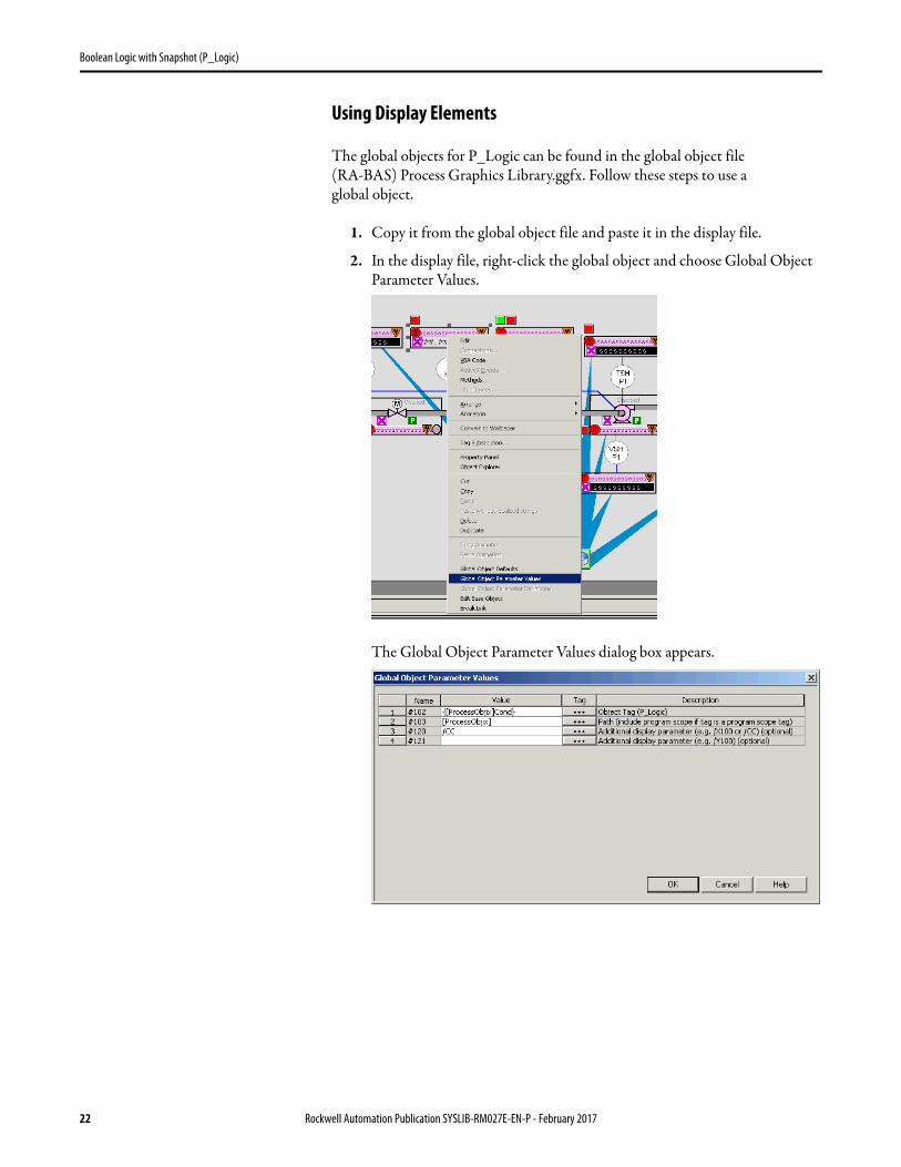
Using Display Elements
The global objects for P_Logic can be found in the global object file(RA-BAS) Process Graphics Library.ggfx. Follow these steps to use aglobal object.
1. Copy it from the global object file and paste it in the display file.
2. In the display file, right-click the global object and choose Global Object Parameter Values.
The Global Object Parameter Values dialog box appears.
22 Rockwell Automation Publication SYSLIB-RM027E-EN-P - February 2017

Boolean Logic with Snapshot (P_Logic)
The global object parameters are as follows.
3. Type the tag or value in the Value column as specified in the Description column.
4. Click OK.
Faceplate The P_Logic faceplate consists of three tabs and each tab consists of one or more pages.
Each faceplate contains the value of local configuration tags Cfg_Tag and Cfg_Desc in the title bar.
Click the appropriate icon at the top of the faceplate to access a specific tab.
The faceplate provides the means for operators, maintenance personnel,engineers, and others to interact with the P_Logic Instruction instance,including viewing its status and values and manipulating it through itscommands and settings.
Parameter Required Description
#102 Y Object tag to point to the name of the associated object Add-On Instruction in the controller.
#103 Y Path used for display navigation features to other objects. Include program scope if tag is a program scope tag.
#120 N Additional parameter to pass to the display command to open the faceplate. Typically used to define position for the faceplate.
#121 N Additional parameter to pass to the display command to open the faceplate. if defining X and Y coordinate, separate parameters so that X is defined by #120 and Y is defined by #121. This lets the same parameters be used in subsequent display commands originating from the faceplate.
TIP You can click the ellipsis (…) to browse and select a tag.
Values for items marked ‘(optional)’ can be left blank.
Operator
Snapshot
Engineering
Help
Exit
Rockwell Automation Publication SYSLIB-RM027E-EN-P - February 2017 23

Boolean Logic with Snapshot (P_Logic)
Operator Tab
The Faceplate initially opens to the Operator (‘Home’) tab. From here, an operator can monitor the device status and manually operate the device.
The Operator tab shows the following information:• The eight Boolean inputs and eight logic gates, with each gate having a
maximum of four sources.• Configurable operator snapshot command button creates an image of the
logic.• Provides a progress indicator for the on-delay time and off-delay time for
the instruction’s output. See Engineering Tab on page 26 for on-delay and off-delay configuration.
The following table shows the functions included on the Operator tab.
Snapshot Button
Output State
Input Names
Gate
Table 10 - Operator Tab Description
Function Action Security
Input Name Click to navigate to the Input object faceplate. None
Click to take a snapshot of the current state.
IMPORTANT: When you take a snapshot, the View Snapshot tab is automatically displayed.
Manual Device Operation (Code B)
Gate Click one of the gates to access the Gate Configuration display for that gate.
See Gate Configuration Display on page 29.
24 Rockwell Automation Publication SYSLIB-RM027E-EN-P - February 2017
Boolean Logic with Snapshot (P_Logic)
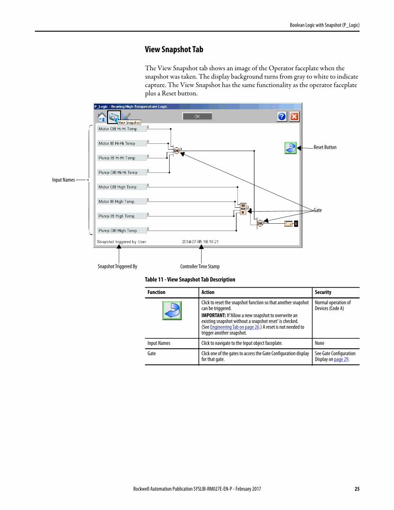
View Snapshot Tab
The View Snapshot tab shows an image of the Operator faceplate when the snapshot was taken. The display background turns from gray to white to indicate capture. The View Snapshot has the same functionality as the operator faceplate plus a Reset button.
Snapshot Triggered By Controller Time Stamp
Reset Button
Gate
Input Names
Table 11 - View Snapshot Tab Description
Function Action Security
Click to reset the snapshot function so that another snapshot can be triggered.
IMPORTANT: If ‘Allow a new snapshot to overwrite an existing snapshot without a snapshot reset' is checked. (See Engineering Tab on page 26.) A reset is not needed to trigger another snapshot.
Normal operation of Devices (Code A)
Input Names Click to navigate to the Input object faceplate. None
Gate Click one of the gates to access the Gate Configuration display for that gate.
See Gate Configuration Display on page 29.
Rockwell Automation Publication SYSLIB-RM027E-EN-P - February 2017 25

Boolean Logic with Snapshot (P_Logic)
Engineering Tab
The Engineering tab provides access to device configuration parameters and ranges, options for device and I/O setup, displayed text, andfaceplate-to-faceplate navigation settings, and for initial system commissioning or later system changes.
The Engineering page is divided into two pages.
Engineering Tab Page 1
Page 1 of the Engineering tab shows the following information:• Description, label, and tag• Time stamp configuration text• Output display text and delay time configuration• Condition options to save a snapshot
Configure DeviceDescription, Label, and Tag
Configure Display TextWhen Output = 1 or 0
Configure Off/On-DelayTimes (Seconds)
26 Rockwell Automation Publication SYSLIB-RM027E-EN-P - February 2017

Boolean Logic with Snapshot (P_Logic)
The following table lists the functions on page one of the Engineering tab.Table 12 - Engineering Tab Page 1 Description
Function Action Security Configuration Parameters
Description Type the description to show on the Faceplate title bar.
Engineering Configuration (Code E)
Cfg_Desc
Label Type the label to show on the graphic symbol.
Cfg_Label
Tag Type the tag name to show on the faceplate and tooltip.
TIP: Pausing the mouse over this field displays a tooltip with the configured Logic tag/path.
Cfg_Tag
Text to Display when Output = 0
Type the text to display on the faceplate when output = 0.
Cfg_0StText
Text to Display when Output = 1
Type the text to display on the faceplate when output = 1.
Cfg_1StText
Input to delay timers is inverted
Check to invert the selected output before it is passed to the output delay timers.
Cfg_OutSrcInv
Output Off delay time (seconds)
Type a value for the output off-delay time.
Cfg_OffDelay
Output On delay time (seconds)
Type a value for the outputon-delay time.
Cfg_OnDelay
Generate a controller time stamp when snapshot occurs
Check to generate a time stamp whenever a snapshot triggers.
Cfg_TSonSnap
Allow a new snapshot to overwrite an existing snapshot without a snapshot reset
Check to allow a new snapshot t‘o be triggered without having to reset the previous snapshot.
Cfg_SnapOver
Save State to Snapshot When: Inp_Hold transitions from 0 to 1
Check to trigger a snapshot when the Inp_Hold signal transitions from 0 to 1.
Engineering Configuration (Code E)
Cfg_UseInpHold
Save State to Snapshot When: Output transitions from 0 to 1
Check to trigger a snapshot when the Output signal transitions from 0 to 1.
Cfg_UseOut01
Save State to Snapshot When: Output transitions from 1to 0
Check to trigger a snapshot when the Output signal transitions from 1 to 0.
Cfg_UseOut10
Save State to Snapshot When: Requested by Operator (enables snapshot button)
Check to trigger a snapshot when the Operator clicks Snapshot.
Cfg_UseOCmd
Save State to Snapshot When: Requested by program via PCmd_Snap
Check to trigger a snapshot by when program logic sets PCmd_Snap.
Cfg_UsePCmd
Rockwell Automation Publication SYSLIB-RM027E-EN-P - February 2017 27
Boolean Logic with Snapshot (P_Logic)
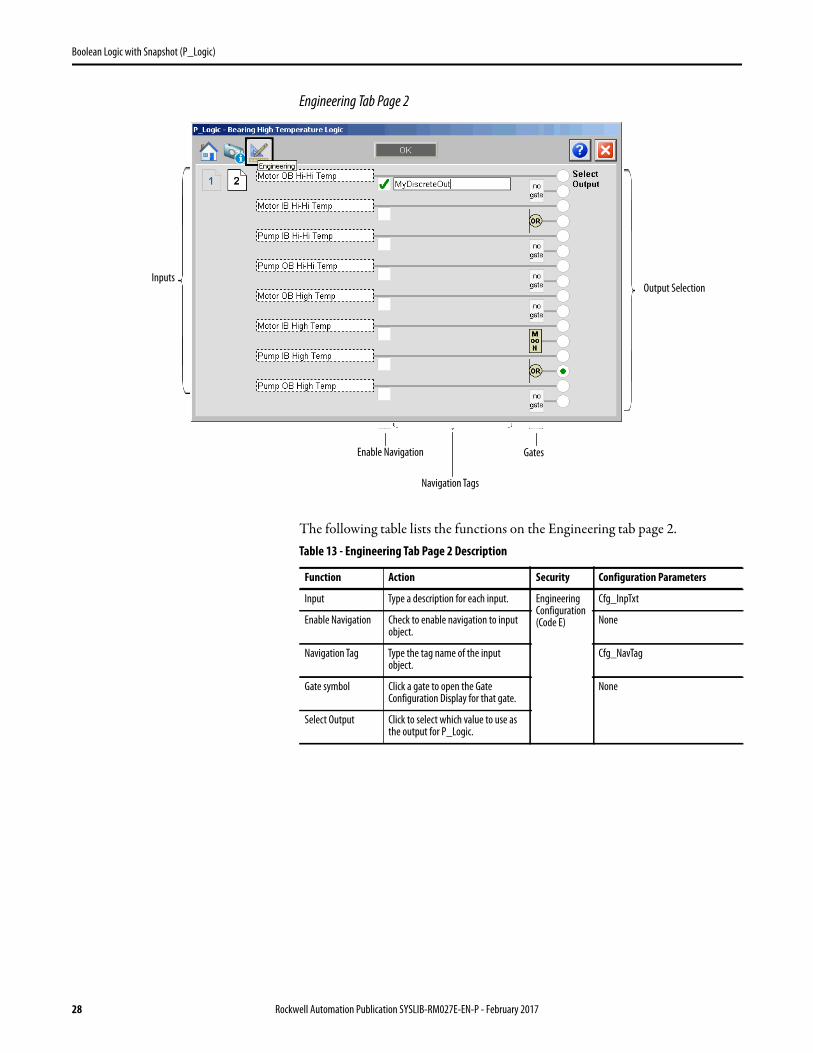
Engineering Tab Page 2
The following table lists the functions on the Engineering tab page 2.
Inputs
Enable Navigation
Navigation Tags
Output Selection
Gates
Table 13 - Engineering Tab Page 2 Description
Function Action Security Configuration Parameters
Input Type a description for each input. Engineering Configuration (Code E)
Cfg_InpTxt
Enable Navigation Check to enable navigation to input object.
None
Navigation Tag Type the tag name of the input object.
Cfg_NavTag
Gate symbol Click a gate to open the Gate Configuration Display for that gate.
None
Select Output Click to select which value to use as the output for P_Logic.
28 Rockwell Automation Publication SYSLIB-RM027E-EN-P - February 2017

Boolean Logic with Snapshot (P_Logic)
Gate Configuration Display
This gate configuration display appears if a gate is clicked in the Operator, View Snapshot, or Engineering tabs.
The following table lists the functions on the gate configuration display.
Gate being Configured
Table 14 - Gate Configuration Message Box Description
Function Action Security
Gate Type Click to select a gate type. Engineering Configuration (Code E)
Use Source Click to select which inputs of the gate are enabled (1…4).
Invert Source Click to invert the source coming into the gate.
Select Source Select which input or gate output is to be used as the source to the gate. The gate outputs that are available depend on which gate is being configured; you can only link to an earlier gate. For example, Gate 3 can link to the outputs of Gates 0…2, but not to outputs of Gates 3…7.
Rockwell Automation Publication SYSLIB-RM027E-EN-P - February 2017 29

Boolean Logic with Snapshot (P_Logic)
Boolean Logic with Snapshot Faceplate Help
30 Rockwell Automation Publication SYSLIB-RM027E-EN-P - February 2017


Publication SYSLIB-RM027E-EN-P - February 2017
Supersedes Publication SYSLIB-RM027D-EN-P - January 2016 Copyright © 2017 Rockwell Automation, Inc. All rights reserved. Printed in the U.S.A.
Rockwell Automation Support
Rockwell Automation provides technical information on the Web to assist you in using its products.At http://www.rockwellautomation.com/support you can find technical and application notes, sample code, and links to software service packs. You can also visit our Support Center at https://rockwellautomation.custhelp.com/ for software updates, support chats and forums, technical information, FAQs, and to sign up for product notification updates.
In addition, we offer multiple support programs for installation, configuration, and troubleshooting. For more information, contact your local distributor or Rockwell Automation representative, or visithttp://www.rockwellautomation.com/services/online-phone.
Installation Assistance
If you experience a problem within the first 24 hours of installation, review the information that is contained in this manual. You can contact Customer Support for initial help in getting your product up and running.
New Product Satisfaction Return
Rockwell Automation tests all of its products to help ensure that they are fully operational when shipped from the manufacturing facility. However, if your product is not functioning and needs to be returned, follow these procedures.
Documentation Feedback
Your comments will help us serve your documentation needs better. If you have any suggestions on how to improve this document, complete this form, publication RA-DU002, available at http://www.rockwellautomation.com/literature/.
United States or Canada 1.440.646.3434
Outside United States or Canada Use the Worldwide Locator at http://www.rockwellautomation.com/rockwellautomation/support/overview.page, or contact your local Rockwell Automation representative.
United States Contact your distributor. You must provide a Customer Support case number (call the phone number above to obtain one) to your distributor to complete the return process.
Outside United States Please contact your local Rockwell Automation representative for the return procedure.
Rockwell Otomasyon Ticaret A.Ş., Kar Plaza İş Merkezi E Blok Kat:6 34752 İçerenköy, İstanbul, Tel: +90 (216) 5698400
Rockwell Automation maintains current product environmental information on its website at
http://www.rockwellautomation.com/rockwellautomation/about-us/sustainability-ethics/product-environmental-compliance.page.