Embed Size (px)
Citation preview

Robust high order integral equation solvers forelectromagnetic scattering in complex geometries
Zydrunas Gimbutas
Courant Institute of Mathematical SciencesNew York University
November 29, 2012

Overview
This is joint work with
James Bremer (U. California, Davis)
Charles L. Epstein (U. Pennsylvania)
Leslie Greengard (Courant Institute, NYU)
Andreas Kloeckner (Courant Institute, NYU)
Michael O’Neil (Courant Institute, NYU)
Felipe Vico (Polytechnic University of Valencia, Spain)
Bogdan Vioreanu (U. Michigan)

Applications: Scattering in complex geometry
Electromagnetic compatibility problems, antenna design.Michielsen (U. Michigan)
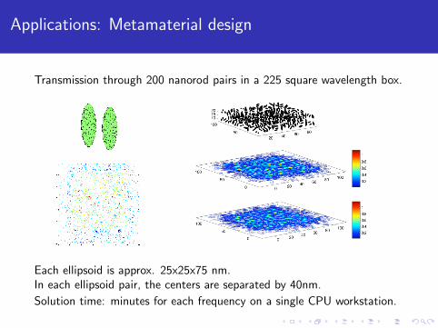
Applications: Metamaterial design
Transmission through 200 nanorod pairs in a 225 square wavelength box.
Each ellipsoid is approx. 25x25x75 nm.In each ellipsoid pair, the centers are separated by 40nm.
Solution time: minutes for each frequency on a single CPU workstation.
Outline of talk
Classical integral representations for Maxwell’s equations
Spurious resonances and “low-frequency breakdown”
Augmented charge-current integral equations
High order discretization of surfaces and solution densities
Singular layer potentials and quadratures for local interactions
Numerical experiments

The Maxwell’s equations
A classical problem in electromagnetics concerns thescattering of waves from an obstacle. In the time-harmoniccase, the electric and magnetic fields are given by
E(x, t) = E(x)e−iωt , H(x, t) = H(x)e−iωt . (1)
In regions free of charge/current, the spatial componentssatisfy the time-harmonic Maxwell’s equations:
∇×H = −iωεE, ∇× E = iωµH, (2)
∇ · εE = 0, ∇ · µH = 0. (3)
where ε, µ are permittivity, permeability of exterior region Ω.

The Maxwell’s equations: Scattering theory
In electromagnetic scattering, the total field Etot , Htot isgenerally written as a sum
Etot(x) = Ein(x) + Escat(x), Htot(x) = Hin(x) + Hscat(x), (4)
where Ein, Hin describe a known incident field andEscat , Hscat denote the scattered field of interest.

The Maxwell’s equations: Vector and scalar potentials
The integral representations for the scattered electromagnetic fieldE(x), H(x) are based on classical vector and scalar potentials
E(x) = iωA(x)−∇φ(x), H(x) =1
µ∇× A(x), (5)
where
A(x) = µ
∫Γgk(x− y)J(y)dAy, (6)
φ(x) =1
ε
∫Γgk(x− y)ρ(y)dAy, (7)
gk(x) = e ik|x|/4π|x| is the Green’s function for the scalarHelmholtz equation, Γ is the boundary, k = ω
√εµ, with the
continuity condition
∇ · J(x) = iωρ(x). (8)

The Maxwell’s equations: Dyadic Green’s functions
By incorporating the continuity condition into the integralrepresentations
E(x) = iωµ
∫Γ
[I +∇∇k2
]gk(x− y)J(y)dAy, (9)
H(x) = ∇×∫
Γgk(x− y)J(y)dAy, (10)
we obtain the electric and magnetic dyadic Green’s functions
Ge(x, y) =
[I +∇∇k2
]gk(x− y), (11)
Gm(x, y) = ∇× Ge(x, y) = ∇× gk(x− y). (12)

The Maxwell’s equations: Boundary conditions
For a perfect conductor, the boundary conditions to beenforced are:
n× Etot = 0, n ·Htot = 0, (13)
n×Htot = J, n · Etot =ρ
ε. (14)
For uniqueness, with Im(k) ≥ 0, we assume that the solutionsatisfies the Sommerfeld (Silver-Muller) radiation condition:
limr→∞
|r|[Hscat(r)× r
|r|−√ε
µEscat(r)
]= 0. (15)

The EFIE and MFIE (Maue)
The electric field integral equation (EFIE) solves for theunknown current J by enforcing n× Etot = 0. It involves ahypersingular operator acting on J:
iωµn×∫
Γ
[I +∇∇k2
]gk(x− y)J(y)dAy = −n× Einc(x).
The magnetic field integral equation (MFIE) solves for theunknown current J by enforcing n×Htot = J.
There exists a set of frequencies ωj for which the integralequations are not invertible - i.e. spurious resonances.

The Combined Field Integral Equation
The CFIE (and CSIE) were introduced in the 1970’s byHarrington, Miller, Mautz, Poggio and others. It avoidsspurious resonances by taking a complex linear combination ofthe EFIE and the MFIE
Not a Fredholm equation of the second kind
Other approaches (Yaghjian, ...)

Preconditioners
Adams and Contopanagos et al. made use of the fact that thecomposition of the hypersingular EFIE operator with itselfequals the sum of the identity operator and a compactoperator. Leads to CFIE that is resonance-free.
Christiansen & Nedelec, Colton & Kress, Bruno & Elling &Paffenroth & Turc, Andriulli & Cools & Bagci & Olyslager &Buffa & Christiansen & Michielssen have designedCalderon-based strategies for the EFIE and CFIE.
Implementation of these schemes rather involved (interactionwith corners and edges)

Low frequency breakdown
In the Maxwell system, a separate problem stems from therepresentation of the electric field itself:
Escat = iωA− 1
iωε∇∫
Γgk(x− y)(∇ · J)(y)dAy.
Numerical discretization as ω → 0 leads to loss of accuracy,generally referred to as “low-frequency breakdown”.

Low frequency breakdown
The usual remedy for low frequency breakdown involves the use ofspecialized basis functions in the discretization of the current, suchas the “loop and tree” method of Wilton and Glisson.
This is a kind of discrete surface Helmholtz decomposition of apiecewise linear approximation of J.
As the frequency goes to zero, the irrotational and solenoidaldiscretization elements become uncoupled, avoiding the scalingproblem that causes loss of precision.

Auxiliary variables
An alternative is to introduce electric charge ρ as an additionalvariable (Scharstein, Taskinen, Yla-Oijala, Chew).
φ(x) =1
ε
∫Γgk(x− y)ρ(y)dAy
as well as the continuity condition
∇ · J = iωρ.
This avoids low-frequency breakdown, but is now a Fredholmintegral equation subject to a differential-algebraic constraint.

Robust high-fidelity solvers for the Maxwell’s equations
Well-conditioned second kind integral formulations:spurious-resonance free, with localized spectra for better GMRESconvergence
Remove differential-algebraic constraints and hypersingularoperators in integral formulations and field postprocessing
High order description of surfaces and solution densities
High order quadrature schemes for singular layer potentials
Fast O(N) or O(N logN) solvers based on FMM acceleration

Augmented integral equations
We introduce electric charge ρ as an additional variable andsimultaneously impose conditions
n×Htot = J, n · Etot =ρ
ε. (16)
Using the standard jump relations, we obtain a system oflinear equations (the electric current-charge integral equation,ECCIE):
1
2J− K [J] = n×Hinc ,
ρ
2+ S ′k [ρ]− iωεn · A[J] = n · (εEinc),
where
K [J](x) = n×∫
Γ
Gm(x, y)J(y)dAy, S ′k [ρ](x) = n·∇
∫Γ
gk(x, y)ρ(y)dAy.

Augmented integral equations
Vico, G-, Greengard, Ferrando-Bataller:Let (J, ρ) be the solution of the ECCIE at a non-resonantfrequency ω, and let Einc ,Hinc satisfy the Maxwell’sequations in the neighborhood of Ω. Then ∇ · J = iωρ.
For an arbitrary right hand side, the continuity condition isnecessary in order for Escat ,Hscat to satisfy the Maxwell’sequations. Existing charge-current formulation incorporatethis constraint in one form or another.

Outline of proof
Taking the surface divergence of the tangential boundarycondition n×Htot = J, we have:
∇ · J−∇ · (n×H) = ∇ · (n×Hinc),
∇ · J + n · (∇×H) = −n · (∇×Hinc),
∇ · J− n · (iωεE) = n · (iωεEinc).
Using the standard integral representation for E,
∇ · J− n · (iωεA[J]−∇Sk [∇ · J]) = n · (iωεEinc).

Augmented integral equations
Dividing by iω, and taking the limit to the boundary, we have
1
2
∇ · Jiω
+ S ′k
[∇ · Jiω
]− n · iωεA[J] = n · (εEinc). (17)
Recall that the second equation of the ECCIE was:
ρ
2+ S ′k [ρ]− n · iωεA[J] = n · (εEinc).
Therefore, the solution (J, ρ) of the ECCIE satisfies thecontinuity condition ∇ · J = iωρ.
At zero frequency, the equation (17) has a null-space,corresponding to the interior Neumann problem for theLaplace equation.

Augmented integral equations
The solution can be made unique by enforcing that the totalcharge is equal to zero.
1
2ρ+ S ′k [ρ]− n · iωεA[J] = n · (εEinc), (18)∫
Γρ(y)dAy = 0. (19)
The rank-1 correction trick:
S ′k [ρ](x) = n(x)·∇x
∫Γgk(x−y)ρ(y)dAy →∫
Γ[n(x) · ∇xgk(x− y) + 1] ρ(y)dAy. (20)
Useful for dealing with near singular cases.

Low frequency breakdown: near field
The dyadic electric Green’s function for E field:
E(x) = iωµ
∫Γ
[I +∇∇k2
]gk(x− y)J(y)dAy, (21)
is replaced with the charge-current representation:
E(x) = iωµ
∫Γgk(x− y)J(y)dAy −∇
∫Γgk(x− y)ρ(y)dAy.
(22)
Vector and scalar potential parts decouple at low frequencies.

Low frequency breakdown: far field
The far field E signature:
Eα∞(x) = α ·∫
Γe ik x·yJ(y)dAy, (23)
where x is a unit vector in the x direction and α is the angularpolarization of the receiver. For small ω, the far field signatureEα∞ is of the order O(ω), while J is O(1).
In (J, ρ) representation, all terms are of the order O(ω):
Eα∞(x) = α ·∫
Γ
[e ik x·y − 1
]J(y)dAy− iωα ·
∫Γyρ(y)dAy. (24)

Low frequency breakdown
Vico, Gimbutas, Greengard, Ferrando-Bataller, “OvercomingLow-Frequency Breakdown of the Magnetic Field IntegralEquation”, to appear in IEEE Transactions on Antennas andPropagation.
Augmented integral equations
Integral formulations using the second set of boundary conditions
n× Etot = 0, n ·Htot = 0, (25)
lead to the augmented electric field integral equations:
n× iωµ
∫Γ
gk(x− y)J(y)dAy − n×∇∫
Γ
gk(x− y)ρ(y)dAy = −n× Einc ,
n · ∇ ×∫
Γ
gk(x− y)J(y)dAy = −n ·Hinc .
The off-diagonal blocks are Hilbert (Riesz) operators.Currently very active research area: charge-current formulations(Taskinen, Yla-Oijala), generalized Debye integral equations(Epstein, Greengard), etc.

Discretization schemes
Classical integral representations for Maxwell’s equations
Spurious resonances and “low-frequency breakdown”
Augmented charge-current integral equations
High order discretization of surfaces and solution densities
Singular layer potentials and quadratures for local interactions

Discretization of singular layer potentials
The numerical schemes for discretizing the ECCIE and augmentedEFIE require accurate evaluation of the following singular layerpotentials:
n×∫
ΓGm(x, y)J(y)dAy, n · ∇
∫Γgk(x, y)ρ(y)dAy,∫
Γgk(x− y)J(y)dAy, −n×∇
∫Γgk(x− y)ρ(y)dAy,
n · ∇ ×∫
Γgk(x− y)J(y)dAy,
and good representations for the scatterer Γ, solution (J, ρ) andincoming field Einc ,Hinc.
Surface descriptors
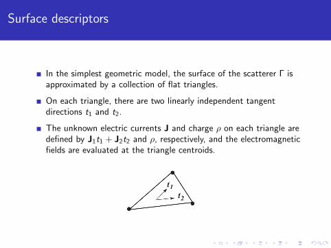
In the simplest geometric model, the surface of the scatterer Γ isapproximated by a collection of flat triangles.
On each triangle, there are two linearly independent tangentdirections t1 and t2.
The unknown electric currents J and charge ρ on each triangle aredefined by J1t1 + J2t2 and ρ, respectively, and the electromagneticfields are evaluated at the triangle centroids.

Surface descriptors
Flat triangulations with constant densities: single layer potentials areaccurate to O(h2), double layer potentials - O(h), hypersingular . . .
Very slow convergence rates; codes are hard to test
Limited choice of useful integral representations
At least quadratic surface patches are needed
Cubic and high order surface patches!
Interfacing with CAD packages

Solution discretization
To represent current and charge densities, we use high orderGaussian-like interpolation/quadrature rules for smooth functions ontriangles, Rokhlin-Vioreanu.
These are also the collocation nodes (selected in the interior of eachpatch) where we evaluate the electromagnetic fields and impose theboundary conditions.

Solution discretization
The nodes are fully symmetric, well-conditioned, and the correspondingquadrature weights are positive.
interp 0 1 2 3 4 5 6 7 8 9 10quadr 1 2 4 5 7 8 10 12 14 15 17nodes 1 3 6 10 15 21 28 36 45 55 66
cond # 1.0 1.0 1.4 1.9 2.1 3.4 4.3 4.8 4.8 6.5 8.1
The table contains the degree of intepolation, the degree of quadrature,the number of nodes, and the condition number of interpolation processfor R.-V. nodes up to degree 10.
Arbitrary degree rules are available.
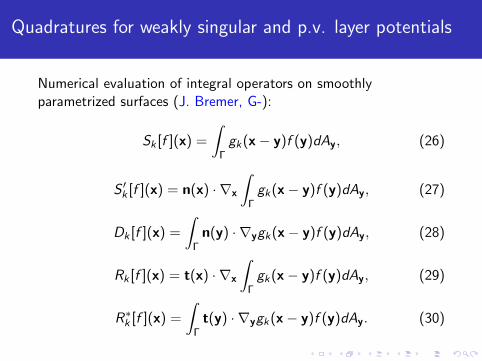
Quadratures for weakly singular and p.v. layer potentials
Numerical evaluation of integral operators on smoothlyparametrized surfaces (J. Bremer, G-):
Sk [f ](x) =
∫Γgk(x− y)f (y)dAy, (26)
S ′k [f ](x) = n(x) · ∇x
∫Γgk(x− y)f (y)dAy, (27)
Dk [f ](x) =
∫Γn(y) · ∇ygk(x− y)f (y)dAy, (28)
Rk [f ](x) = t(x) · ∇x
∫Γgk(x− y)f (y)dAy, (29)
R∗k [f ](x) =
∫Γt(y) · ∇ygk(x− y)f (y)dAy. (30)

Quadratures for weakly singular and p.v. layer potentials
Γ is subdivided into curved triangular patches Γi .
Density f is represented as a piece-wise smooth function on Γ.
Singular integrals are evaluated on R.-V. interpolation nodesxt = x(uj , vj):
Sk [f ](xt) =
∫Γi
gk(xt − y)f (y)dAy (31)
via auxiliary quadrature nodes yauxs = y(us , vs):
Sk [f ](xt) =∑s
wsgk(xt − yauxs )f (yauxs )|A(yauxs )|, (32)
where ws are the auxiliary quadrature weights and |A| is thesurface area element.

Quadratures for weakly singular and p.v. layer potentials
The auxiliary quadratures strongly depend on the locations ofinterpolation nodes in R3 and the stretching factors ofpatches Γi .
The number of auxiliary quadrature nodes is approximately ofthe order 1000–2000; we use a set of precomputed tables forup-to 20th degree polynomials.

Quadratures for weakly singular and p.v. layer potentials
The number of auxiliary quadrature nodes is roughly the same for allinterpolation points.
Numerical experiments
Classical integral representations for Maxwell’s equations
Spurious resonances and “low-frequency breakdown”
Augmented charge-current integral equations
High order discretization of surfaces and solution densities
Singular layer potentials and quadratures for local interactions
Numerical experiments

Accuracy testing
How do we test these codes?
Generate a known solution due to an electromagnetic source(electric dipole, plane wave, . . . )
Grab Etest ,Htest on the surface Γ and use as data
Solve the integral equation for (J, ρ)
Compare E,H to known Etest ,Htest inside the conductor
We use the total field extinction theorem, which is due to theinhomogeneous boundary conditions
n×Htot = J, n · Etot =ρ
ε. (33)

Numerical results: Smooth geometries
The ECCIE:n×Htot = J,n · Etot = ρ, k = 1
Ntri Ndisc Nsys Esph
12 540 1620 5.92E-0548 2160 6480 5.46E-09
192 8640 25920 1.85E-128th order convergence tests
45 points/triangle
sphere
The augmented EFIE:n× Etot = 0,n · Etot = ρ, k = 1
Ntri Ndisc Nsys Esph
12 540 1620 1.01E-0248 2160 6480 4.41E-05
192 8640 25920 8.11E-078th order convergence tests
45 points/triangle
ellipsoid

Numerical experiments: Singular geometries
The Helmholtz equation (exterior Neumann boundary condition).
x(s, t) = 2 sin(t/2),
y(s, t) = − cos(s) sin(t),
z(s, t) = sin(s) sin(t),
0 ≤ t ≤ π, 0 ≤ s ≤ 2π.
Ntri Ndisc Nsys Esph
4 180 180 1.52E-0316 720 720 2.42E-0564 2880 2880 1.04E-07
256 11520 11520 9.09E-101024 46080 46080 7.04E-13
8th order convergence tests45 points/triangle
The domain is discretized using an adaptive mesh, (Bremer)Recompression schemes, (Bremer, Helsing)
Numerical experiments
Fully resolved EM simulations
10,000-100,000 of discretization nodes for simple objectsMillions of points for complex geometries
Corners and edges
Adaptive mesh refinementRecompression schemes (Bremer, Helsing)

Numerical results
The solution of the MFIE (current J) is plotted on the right. The solutionof the scalar equation in the ECCIE formulation yields the charge densityρ, plotted on the left. The arch is constructed from the concatenation offive cubes - each of which is discretized using an adaptive mesh refinedtoward the edges. The wavenumber (k) was set to 1, and the direction ofincidence was along the z-axis with E polarized along the x-axis.

Future Work
Fast layer potential evaluation tools (FMM acceleration)
Coupling to CAD tools: quadratic and higher order patches
Singular densities: corner and edge compressors
Integral representations with localized spectra
Integral representations for surfaces with complicated topology
Integration into variety of application codes: antennas oncomplex platforms, MRI, metamaterial design

Thanks
AFOSR MURI Grant FA9550-06-1-0337,
Courant Mathematics and Computing Laboratory,
DoD NSSEFF Program Award FA9550-10-1-0180.


![Solving Vlasov Equation for Beam Dynamics Simulation · than [5] and developed scalable Poisson and Vlasov solvers to make use of the BG/P supercomputer at ANL. VLASOV EQUATION The](https://img.dokumen.tips/doc/110x75/60b9dbca4bcb073046191215/solving-vlasov-equation-for-beam-dynamics-simulation-than-5-and-developed-scalable.jpg)