Embed Size (px)
Citation preview
ROBUST CONTROL OF AN A-DOUBLE WITH ACTIVE DOLLY BASED ONSTATIC OUTPUT FEEDBACK AND DYNAMIC FEED-FORWARD
Maliheh Sadeghi Kati Hakan Köroglu Jonas Fredriksson
Chalmers University of Technology, Dept. Signals and Systems, Gothenburg,Sweden
AbstractA steering-based control is proposed for improving the lateral performance of anA-double combination with an active dolly. The controller is based on static outputfeedback combined with dynamic feed-forward and is designed to ensure an H∞performance objective in the face of parametric uncertainty. The synthesis is per-formed via linear matrix inequality (LMI) optimizations. Two feed-forward designmethods are proposed and one of them is highlighted as the more rigorous approachfor dealing with parametric uncertainty. The verification results confirm a significantreduction in rearward amplification of yaw rates and high speed transient off-trackingeven when the dynamic feed-forward from the tractor steering angle accompaniesthe static feedback only from the articulation angles.
Keywords: Static output feedback , Dynamic feedforward, H∞ synthesis , LMI basedcontrol, Rearward amplification, Active dolly
1

1. Introduction
Rapid growth in the transportation of goods has led to an increased demand for highcapacity transport (HCT) vehicles, leading to raised concerns about environmentaleffects, road freight traffic and increased infrastructure usage. Increasing cost of fuel,congestions and gas emissions make long heavy vehicle combinations (LHVCs) asattractive alternatives to conventional heavy vehicle combinations (CHVCs) in goodstransportation (H. Backman and R. Nordström (2002), J. Woodrooffe and L. Ash(2001)).
One major issue concerning LHVCs is their potential impacts on traffic safety. Roadsafety performance of LHVCs depends on the technical features such as powertrain and braking systems capability, lateral dynamical stability and maneuverability.Specific performance measures are introduced to assess the vehicle behaviour fromvarious aspects. The most common measure is the so-called rearward amplification(RWA) of the yaw rate or lateral acceleration to assess the high speed lateral per-formance of HCT vehicles. Steering and braking based control are two main controlstrategies to improve the high-speed lateral performance of HCT vehicles. Severalworks have already proposed to reduce the yaw rate or lateral acceleration RWA forvarious HCT vehicles by using active trailer steering (see e.g. S. Kharrazi (2012) andthe references therein).
The aim of this paper is to improve the high speed lateral performance of an A-doublecombination by controlling an active dolly. The dolly is a small unit in the A-doublecombination and therefore active dolly steering is more economical and convenient(M. M. Islam, L. Laine, and B. Jacobson (2015)). The potential improvements by con-trolling the dolly have been studied in (M. S. Kati, L. Laine, and B. Jacobson (2014)) byusing a simple feedback control strategy. M. M. Islam, L. Laine, and B. Jacobson (2015)have proposed a feed-forward controller based on a nonlinear inversion techniqueand investigated controlled system sensitivity against the uncertainty in the steeringactuator parameters.
In this paper, we propose a combined static output feedback and dynamic feed-forward controller which is designed to be robust against the variations in the steeringactuator parameters. Such a scheme is shown to improve the lateral performance ofan A-double combination as justified by frequency domain analysis and time-domainsimulations.
2. Vehicle Model
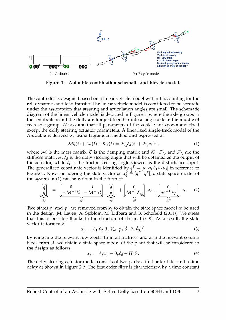
An A-double combination consists of a tractor as the lead unit and two semitrailerslinked together by a dolly converter unit as shown in Figure 1. Since the dolly isthe smallest among all A-double units, its axles are chosen to be steerable for yawrate control of the A-double, while the axles of the other units stay unchanged. TheA-double is considered with a total weight of 80 tons and a total length of about 31.5meters. Figure 1 shows an A-double with steerable axles identified by green tyres.
Robust Control of an A-double with Active Dolly based on SOFB and DFF 2
(a) A-double
Vy4Vx3
Vx4
Vy3
Vy2Vx2
Vy1
Vx1
θ3
θ2
θ1
δt
φ1
φ2
φ3
φ4
δd
X
Y
φ
Vx: longitudinal velocity
Vy: lateral velocity
φ : yaw angle
θ: articulation angle
δt:steering angle of the tractor
δd:steering angle of the dolly
(b) Bicycle model
Figure 1 – A-double combination schematic and bicycle model.
The controller is designed based on a linear vehicle model without accounting for theroll dynamics and load transfer. The linear vehicle model is considered to be accurateunder the assumption that steering and articulation angles are small. The schematicdiagram of the linear vehicle model is depicted in Figure 1, where the axle groups inthe semitrailers and the dolly are lumped together into a single axle in the middle ofeach axle group. We assume that all parameters of the vehicle are known and fixedexcept the dolly steering actuator parameters. A linearized single-track model of theA-double is derived by using lagrangian method and expressed as
Mq(t) + C q(t) +Kq(t) = Fδd δd(t) +Fδt δt(t), (1)
where M is the mass matrix, C is the damping matrix and K , Fδd and Fδt are thestiffness matrices. δd is the dolly steering angle that will be obtained as the output ofthe actuator, while δt is the tractor steering angle viewed as the disturbance input.The generalized coordinate vector is identified by qT = [y1 ϕ1 θ1 θ2 θ3] in reference toFigure 1. Now considering the state vector as xT
q , [qT qT], a state-space model ofthe system in (1) can be written in the form of[
]︸︷︷︸
xq
=
[0 I
−M−1K −M−1C
]︸ ︷︷ ︸
A
]︸︷︷︸
xq
+
[0
M−1Fδd
]︸ ︷︷ ︸
B
δd +
[0
M−1Fδt
]︸ ︷︷ ︸
H
δt. (2)
Two states y1 and ϕ1 are removed from xq to obtain the state-space model to be usedin the design (M. Levén, A. Sjöblom, M. Lidberg and B. Schofield (2011)). We stressthat this is possible thanks to the structure of the matrix K. As a result, the statevector is formed as
xp = [θ1 θ2 θ3 Vy1 ϕ1 θ1 θ2 θ3]T. (3)
By removing the relevant row blocks from all matrices and also the relevant columnblock from A, we obtain a state-space model of the plant that will be considered inthe design as follows:
xp = Apxp + Bpδd + Hpδt. (4)
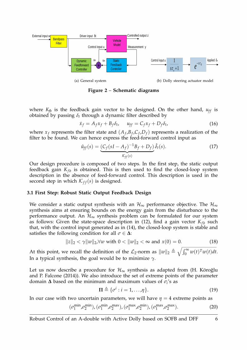
The dolly steering actuator model consists of two parts: a first order filter and a timedelay as shown in Figure 2.b. The first order filter is characterized by a time constant
Robust Control of an A-double with Active Dolly based on SOFB and DFF 3
of τa, while the second part is modeling a transport delay of τd. The transfer functionof the time delay is approximated by a first order Padé-approximation as follows:
e−sτd ≈ 1− 0.5τd1 + 0.5τd
. (5)
We then introduce a state space realization of the actuator model as
xa =
[−2/τd 01/τa −1/τa
]︸ ︷︷ ︸
Aa(σ)
xa +
[4/τd−1/τa
]︸ ︷︷ ︸
Ba(σ)
u, δd =[0 1
]︸ ︷︷ ︸Ca
xa +[0]︸︷︷︸
Da
u,(6)
where u is the control input to be designed. Note that the actuator dynamics dependrationally on τa and τd, which will be considered as uncertain. In order to simplify thetype of dependence, we introduce two new parameters as σ1 = 1/τa and σ2 = 1/τd.In this fashion, we obtain an equivalent representation of the system with affinedependence on σ = (σ1,σ2) as
xa = Aa(σ)xa + Ba(σ)u, δd = Caxa + Dau. (7)
It is assumed that the uncertain parameter vector is known to be in the followingset:
∆ , {σ = (σ1,σ2) : σi ∈ [σmini ,σmax
i ],i = 1,2}. (8)
In addition, to characterize typical driver behaviour, we assume that the frequencycontent of δt is concentrated in a specific frequency range. Therefore, we introducean artificial bandpass filter with a realization as
xb = Abxb + Bbw, δt = Cbxb + Dbw, (9)
where xb and w are the artificial state vector and disturbance input respectively.In this paper, we consider a simple second-order band-pass filter. With the Laplacetransform of w(t) represented as w(s), we express the tractor steering angle as
δt(s) =2ζωcs
s2 + 2ζωcs + ω2c︸ ︷︷ ︸
W(s)
w(s), (10)
where ωc is identified as the frequency at which the filter gain is one. The 3-dBbandwidth of this filter is identified as [ωl,ωh], where the lower and upper limits aregiven by
ωl =(
1 + 2ζ2 −√(1 + 2ζ2)2 − 1
)ωc, ωh =
(1 + 2ζ2 +
√(1 + 2ζ2)2 − 1
)ωc.
(11)The bandwidth of the filter needs to be chosen based on typical and realistic driverinputs. We now append the steering actuator dynamics and the bandpass filter to
Robust Control of an A-double with Active Dolly based on SOFB and DFF 4
the dynamics of the plant to obtain a complete state-space description as
x =
Ap BpCa HpCb0 Aa(σ) 00 0 Ab
︸ ︷︷ ︸
A(σ)
xpxaxb
︸ ︷︷ ︸
x
+
HpDb0Bb
︸ ︷︷ ︸
H
w +
BpDaBa(σ)
0
︸ ︷︷ ︸
B(σ)
u,
z =[Cp DpCa GpCb
]︸ ︷︷ ︸C
x + GpDb︸ ︷︷ ︸G
w +[DpDa
]︸ ︷︷ ︸D
u, (12)
y =[Sp 0 RpCb
]︸ ︷︷ ︸S
x +[RpDb
]︸ ︷︷ ︸R
w,
where z = Cpxp + Dpδd + Gpδt is the signal used for performance evaluation and y =Spxp + Rpδt is the measured output. We emphasize that the parameter dependenceis obtained only in the A and B matrix in this model.
As we will detail in the next section, the design objective will be to synthesize a fixedcontroller such that the controlled system behaves in a desirable way for all valuesof σ = (σ1,σ2) within the domain given in (8).
3. Control Design
The objective of the lateral controller is to suppress undesired yaw rate rearwardamplification (RWA) in the towed units by active steering of the dolly in a singlelane change maneuver. We propose a static output feedback controller plus a dynamicfeed-forward for this purpose. The closed loop system schematic diagram is shownin Figure 2.a. In this section, we first provide a suitable formulation of the problemand then present possible synthesis procedures based on LMI optimization.
The objective of the controller is to determine the required steering angle for the dollyto suppress the yaw rate RWA of the last semitrailer. Requiring this might cause anincrease in the yaw rate of the dolly. In order to avoid high RWA both in the dollyand the last semitrailer, we choose the performance output as
z =
[λr3
(1− λ)r4
]. (13)
where λ ∈ [0,1) is a scalar that can be used to adjust the relative emphasis on thedolly and the second semitrailer.
The control law for the synthesis problem is given by
u(t) = ufb(t) + uf f (t), (14)
where ufb is the static output feedback control input and uf f is the dynamic feed-forward control input. We consider generating the feedback control input ufb as
ufb(t) = Kfby(t), (15)
Robust Control of an A-double with Active Dolly based on SOFB and DFF 5
Vehicle
Model
Controlled output z
Measurement y
External input w
ufb
Bandpass
Filter
Driver input δt
Dynamic
Feedforward
Controller
Static
Feedback
Controller
Control input u
uff
+
(a) General system
e dsControl input u Applied δd
1
1
a
s
(b) Dolly steering actuator model
Figure 2 – Schematic diagrams
where Kfb is the feedback gain vector to be designed. On the other hand, uf f isobtained by passing δt through a dynamic filter described by
x f = A f x f + B f δt, uf f = C f x f + D f δt, (16)
where x f represents the filter state and (A f ,B f ,C f ,D f ) represents a realization of thefilter to be found. We can hence express the feed-forward control input as
uf f (s) = (C f (sI − A f )−1B f + D f )︸ ︷︷ ︸
Kf f (s)
δt(s). (17)
Our design procedure is composed of two steps. In the first step, the static outputfeedback gain K f b is obtained. This is then used to find the closed-loop systemdescription in the absence of feed-forward control. This description is used in thesecond step in which K f f (s) is designed.
3.1 First Step: Robust Static Output Feedback Design
We consider a static output synthesis with an H∞ performance objective. The H∞synthesis aims at ensuring bounds on the energy gain from the disturbance to theperformance output. An H∞ synthesis problem can be formulated for our systemas follows: Given the state-space description in (12), find a gain vector K f b suchthat, with the control input generated as in (14), the closed-loop system is stable andsatisfies the following condition for all σ ∈ ∆:
‖z‖2 < γ‖w‖2,∀w with 0 < ‖w‖2 < ∞ and x(0) = 0. (18)
At this point, we recall the definition of the L2-norm as ‖w‖2 ,√∫ ∞
0 w(t)Tw(t)dt.In a typical synthesis, the goal would be to minimize γ.
Let us now describe a procedure for H∞ synthesis as adapted from (H. Körogluand P. Falcone (2014)). We also introduce the set of extreme points of the parameterdomain ∆ based on the minimum and maximum values of σi’s as
Π , {σi : i = 1, . . . ,η}. (19)
In our case with two uncertain parameters, we will have η = 4 extreme points as
(σmin1 ,σmin
2 ), (σmin1 ,σmax
2 ), (σmax1 ,σmin
2 ), (σmax1 ,σmax
2 ). (20)
Robust Control of an A-double with Active Dolly based on SOFB and DFF 6
We also introduce the associated values of the A matrix as follows:
Ai , A(σi) and Bi , B(σi). (21)
The synthesis can then be realized via the following steps (see H. Köroglu and P.Falcone (2014)):
1) Consider a grid for a positive scalar φ with φ1 = φmin > 0 and φµ = φmax > φmin.2) For each φj,j = 1, . . . ,µ, find γj by solving
γj = arg min{γ : N i(φj) ≺ 0,i = 1, . . . ,η; Y � 0} (22)
where N i is defined in terms of φ and the matrix variables Y = YT ∈ Rk×k,W ∈ Rm×m, N ∈ R1×m as
N i(φ) , He
−φW φ(SY−WS) φR 0BN AiY+BiNS H 00 0 −γ
2 I 0DN CY+DNS G −γ
2 I
. (23)
Here we used HeM ,M+MT to simplify the expression of the LMI condition.The state and output dimensions are represented as k and m respectively.
3) Find the minimum γ as γmin = min{γj : j = 1, . . . ,µ} and construct Kfb byusing (W,N) obtained from the optimization problem associated with γmin asfollows:
Kfb = NW−1. (24)
By applying the feedback control obtained from this step, a new state space realizationcan be obtained for the controlled plant combined with the actuator as follows:
xc =
[Ap + BpDaK f bSp BpCa
BaK f bSp Aa
]︸ ︷︷ ︸
Ac(σ)
[xpxa
]︸ ︷︷ ︸
xc
+
[HpCb + BpDaK f bRpCb
BaK f bRpCb
]︸ ︷︷ ︸
Hb(σ)
xb
+
[HpDb + BpDaK f bRpDb
BaK f bRpDb
]︸ ︷︷ ︸
Hc(σ)
w +
[BpDa
Ba
]︸ ︷︷ ︸
Bc(σ)
uf f , (25)
z =[
Cp + DpDaK f bSp DpCa]︸ ︷︷ ︸
Cc
xc +[
GpCb + DpDaK f bRpCb]︸ ︷︷ ︸
Gb
xb
+[
GpDb + DpDaK f bRpDb]︸ ︷︷ ︸
Gc
w + D︸︷︷︸Dc
uf f , (26)
In this description, uf f is the feed-forward control input which is left to be designedin the next step.
3.2 Second Step: Dynamic Feed-Forward Design
We propose two alternative methods for dynamic feed-forward design. The firstmethod is applicable to a nominal model, while the second one can be used for
Robust Control of an A-double with Active Dolly based on SOFB and DFF 7
an uncertain system as well.
3.2.1 Method 1In this method, we reformulate the problem as an H∞ model matching problem anddesign the dynamic feedforward via standard dynamic output feedbackH∞ synthesis(C. Scherer, P. Gahinet, and M. Chilali (1997)). For this purpose, we fix σ to its nominal(typical or average) value and consider the design for a single model. The problemis then formulated as a standard H∞ model matching problem. To this end, we firstfind the expression of z in the Laplace domain as
z(s) = (Ccl(sI−Acl)−1Hcl+Gc)︸ ︷︷ ︸
G(s)
w(s)+(Ccl(sI−Acl)−1Bcl+Dc)︸ ︷︷ ︸
T (s)
u f f (s).
where we have Acl =
[Ac Hb0 Ab
], Hcl =
[HcBb
], Bcl =
[Bc0
]and Ccl =
[Cc Gb
]. By now
recalling the expression of u f f as in (17), we end up with the following expression:
z(s) =(G(s) + T (s)Kf f (s)W(s)
)w(s). (27)
The standard H∞ model-matching problem aims at finding a stable transfer functionKf f by performing the following H∞-norm minimization:
γopt := minKf f (s) stable
∥∥G(s) + T (s)Kf f (s)W(s)∥∥
∞ . (28)
The transfer matrices G and T are required to be stable and proper, which will be thecase in our problem. This problem is easily reformulated as an H∞ synthesis basedon dynamic output feedback, for which a standard Matlab function can be used.
3.2.2 Method 2In the second method, we use the approach proposed in (H. Köroglu and P. Falcone(2014)) by a modification which is including a weighting filter for the external distur-bance. The feed-forwarded signal is basically a filtered version of external disturbancein the system. In order to reformulate the problem as in (H. Köroglu and P. Falcone(2014)), we first combine the dynamics of the band-pass filter with the dynamics ofthe feed-forward filter as follows:
˙x f =
[Ab 0
B f Cb A f
]︸ ︷︷ ︸
A f
[xbx f
]︸ ︷︷ ︸
x f
+
[Bb
B f Db
]︸ ︷︷ ︸
B f
w, (29)
uf f =[
D f Cb C f]︸ ︷︷ ︸
C f
x f +[
D f Db]︸ ︷︷ ︸
D f
w. (30)
We next re-express the dynamics of the controlled plant from (25)-(26) as
xc = Acxc +[
Hb 0]︸ ︷︷ ︸
Hb
x f + Hcw + Bcuf f , (31)
z = Ccxc +[
Gb 0]︸ ︷︷ ︸
Gb
x f + Gcw + Dcuf f . (32)
Robust Control of an A-double with Active Dolly based on SOFB and DFF 8
and thereby introduce the extended matrices Hb and Gb. By then applying the sameapproach as in (H. Köroglu and P. Falcone (2014)), we obtain an LMI condition forthe performance objective in (18) as follows:
He
AcY Hb + AcV −VA f Hc + BcD f −VB f 0
0 XA f XB f 00 0 −γ
2 I 0CcY Gb + GcV + DcC f Gc + DcD f −γ
2 I
≺ 0. (33)
In this condition Y � 0 and X � 0 are symmetric positive-definite matrix variables,while V is an arbitrary matrix variable. The dimensions of these matrices can beidentified from compatibility. On the other hand, C f and D f are structured matrixvariables that depend on C f and D f as identified from (30). We consider that (A f ,B f )
and thereby (A f ,B f ) are fixed while C f and D f are to be designed. We use the sameform of the realization given in (H. Köroglu and P. Falcone (2014)) where the transferfunction Kf f (s) is expressed as
Kf f (s)=C f (sI−A f )B f +D f =D f +l
∑i=1
C fi(s + ψ)−i. (34)
The variables ψ and l are the pole and the order of the filter to be fixed by the designerbeforehand. Note that the LMI in (33) has affine dependence on the uncertain param-eter σ via the system matrices in (31)-(32), which is suppressed for simplicity. Hencethe parameter-dependent LMI is rendered finite-dimensional simply be imposing itat the extreme points.
4. Simulation Results
In this section, the synthesis procedures developed in the previous sections are ap-plied to a linear vehicle model with vehicle parameters from (M. M. Islam, L. Laine,and B. Jacobson (2015)) and associated simulation results are provided. The A-doubleis equipped with an active dolly where both axles are steerable with the same amountof steering angle. A single lane change manoeuvre is performed at a longitudinalvelocity of 80 Km/h. A sinusoidal steering input is chosen for the input w with anamplitude of 3 deg and a frequency of 0.4 Hz. It is assumed that only the articulationangles are available, i.e. y =
[θ1 θ2 θ3
]T.
Recall that the objective of the controller is to calculate the required u(t) in (14)to minimize the yaw rate of the dolly and the second semitrailer. Thus, the controldesign is provided for the performance indicator in (13) with the weighting coefficientλ = 0.5. With this choice, we place the same emphasis on the yaw rate of both thedolly and the second semitrailer.
The bandpass filter in (10) is used to characterize the tractor steering input with afixed bandwidth of [ωl,ωh]= [2π× 0.2,2π× 0.6] for all cases. The values τa = 0.35 andτd = 0.1 are chosen for the nominal system from the work in (M. M. Islam, L. Laine,and B. Jacobson (2015)). For the uncertain steering actuator model, τa ∈ [0.3,0.4] and
Robust Control of an A-double with Active Dolly based on SOFB and DFF 9
100
−10
−5
0
5
10
15
Singular Values
Frequency (rad/s)
Sin
gula
r V
alue
s (d
B)
No controlFB controlFB+FF control:method 1FB+FF control:method 2
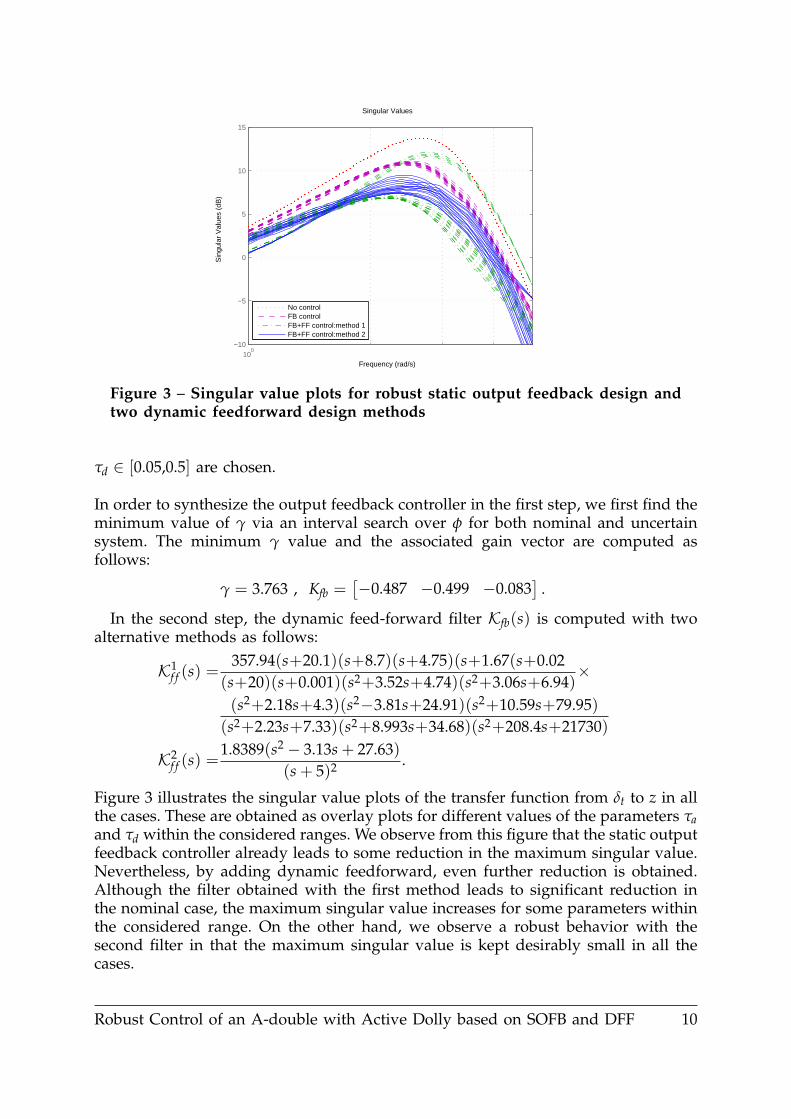
Figure 3 – Singular value plots for robust static output feedback design andtwo dynamic feedforward design methods
τd ∈ [0.05,0.5] are chosen.
In order to synthesize the output feedback controller in the first step, we first find theminimum value of γ via an interval search over φ for both nominal and uncertainsystem. The minimum γ value and the associated gain vector are computed asfollows:
γ = 3.763 , Kfb =[−0.487 −0.499 −0.083
].
In the second step, the dynamic feed-forward filter Kfb(s) is computed with twoalternative methods as follows:
K1f f (s) =
357.94(s+20.1)(s+8.7)(s+4.75)(s+1.67(s+0.02(s+20)(s+0.001)(s2+3.52s+4.74)(s2+3.06s+6.94)
×
(s2+2.18s+4.3)(s2−3.81s+24.91)(s2+10.59s+79.95)(s2+2.23s+7.33)(s2+8.993s+34.68)(s2+208.4s+21730)
K2f f (s) =
1.8389(s2 − 3.13s + 27.63)(s + 5)2 .
Figure 3 illustrates the singular value plots of the transfer function from δt to z in allthe cases. These are obtained as overlay plots for different values of the parameters τaand τd within the considered ranges. We observe from this figure that the static outputfeedback controller already leads to some reduction in the maximum singular value.Nevertheless, by adding dynamic feedforward, even further reduction is obtained.Although the filter obtained with the first method leads to significant reduction inthe nominal case, the maximum singular value increases for some parameters withinthe considered range. On the other hand, we observe a robust behavior with thesecond filter in that the maximum singular value is kept desirably small in all thecases.
Robust Control of an A-double with Active Dolly based on SOFB and DFF 10
0 2 4 6 8 10−0.25
−0.2
−0.15
−0.1
−0.05
0
0.05
0.1
0.15
0.2
No control
Time [s]
Yaw
rat
e [r
ad/s
]
0 2 4 6 8 10−0.25
−0.2
−0.15
−0.1
−0.05
0
0.05
0.1
0.15
0.2
FB control
Time [s]
Yaw
rat
e [r
ad/s
]
Tractor1st semitrailerdolly2nd semitrailer
0 2 4 6 8 10−0.25
−0.2
−0.15
−0.1
−0.05
0
0.05
0.1
0.15
0.2
0.25FB+FF control: method 1
Time [s]
Yaw
rat
e [r
ad/s
]
0 2 4 6 8 10−0.25
−0.2
−0.15
−0.1
−0.05
0
0.05
0.1
0.15
0.2
0.25FB+FF control: method 2
Time [s]
Yaw
rat
e [r
ad/s
]
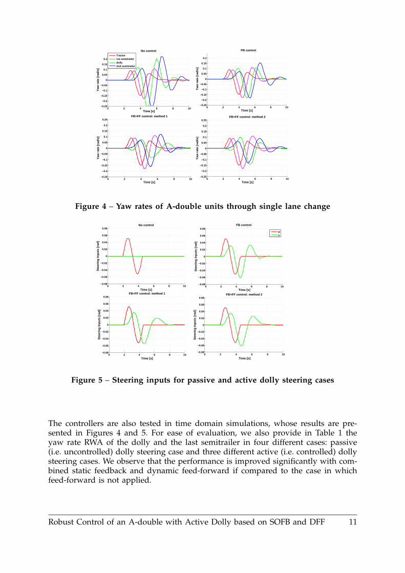
Figure 4 – Yaw rates of A-double units through single lane change
0 2 4 6 8 10−0.08
−0.06
−0.04
−0.02
0
0.02
0.04
0.06
0.08No control
Time [s]
Ste
erin
g In
puts
[rad
]
0 2 4 6 8 10−0.08
−0.06
−0.04
−0.02
0
0.02
0.04
0.06
0.08FB control
Time [s]
Ste
erin
g In
puts
[rad
]
0 2 4 6 8 10−0.08
−0.06
−0.04
−0.02
0
0.02
0.04
0.06
0.08FB+FF control: method 1
Time [s]
Ste
erin
g In
puts
[rad
]
0 2 4 6 8 10−0.08
−0.06
−0.04
−0.02
0
0.02
0.04
0.06
0.08FB+FF control: method 2
Time [s]
Ste
erin
g In
puts
[rad
]
wu
Figure 5 – Steering inputs for passive and active dolly steering cases
The controllers are also tested in time domain simulations, whose results are pre-sented in Figures 4 and 5. For ease of evaluation, we also provide in Table 1 theyaw rate RWA of the dolly and the last semitrailer in four different cases: passive(i.e. uncontrolled) dolly steering case and three different active (i.e. controlled) dollysteering cases. We observe that the performance is improved significantly with com-bined static feedback and dynamic feed-forward if compared to the case in whichfeed-forward is not applied.
Robust Control of an A-double with Active Dolly based on SOFB and DFF 11
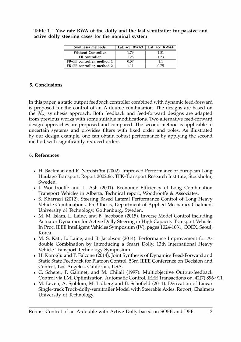
Table 1 – Yaw rate RWA of the dolly and the last semitrailer for passive andactive dolly steering cases for the nominal system
Synthesis methods Lat. acc. RWA3 Lat. acc. RWA4Without Controller 1.79 1.81
FB controller 1.25 1.23FB+FF controller, method 1 0.57 1.1FB+FF controller, method 2 1.11 0.75
5. Conclusions
In this paper, a static output feedback controller combined with dynamic feed-forwardis proposed for the control of an A-double combination. The designs are based onthe H∞ synthesis approach. Both feedback and feed-forward designs are adaptedfrom previous works with some suitable modifications. Two alternative feed-forwarddesign approaches are proposed and compared. The second method is applicable touncertain systems and provides filters with fixed order and poles. As illustratedby our design example, one can obtain robust performance by applying the secondmethod with significantly reduced orders.
6. References
• H. Backman and R. Nordström (2002). Improved Performance of European LongHaulage Transport. Report 2002:6e, TFK-Transport Research Institute, Stockholm,Sweden.
• J. Woodrooffe and L. Ash (2001). Economic Efficiency of Long CombinationTransport Vehicles in Alberta. Technical report, Woodrooffe & Associates.
• S. Kharrazi (2012). Steering Based Lateral Performance Control of Long HeavyVehicle Combinations. PhD thesis, Department of Applied Mechanics ChalmersUniversity of Technology, Gothenburg, Sweden.
• M. M. Islam, L. Laine, and B. Jacobson (2015). Inverse Model Control includingActuator Dynamics for Active Dolly Steering in High Capacity Transport Vehicle.In Proc. IEEE Intelligent Vehicles Symposium (IV), pages 1024-1031, COEX, Seoul,Korea.
• M. S. Kati, L. Laine, and B. Jacobson (2014). Performance Improvement for A-double Combination by Introducing a Smart Dolly. 13th International HeavyVehicle Transport Technology Symposium.
• H. Köroglu and P. Falcone (2014). Joint Synthesis of Dynamics Feed-Forward andStatic State Feedback for Platoon Control. 53rd IEEE Conference on Decision andControl, Los Angeles, California, USA.
• C. Scherer, P. Gahinet, and M. Chilali (1997). Multiobjective Output-feedbackControl via LMI Optimization. Automatic Control, IEEE Transactions on, 42(7):896-911.
• M. Levén, A. Sjöblom, M. Lidberg and B. Schofield (2011). Derivation of LinearSingle-track Truck-dolly-semitrailer Model with Steerable Axles. Report, ChalmersUniversity of Technology.
Robust Control of an A-double with Active Dolly based on SOFB and DFF 12


![Robust Model Predictive Control - Carnegie Mellon …cepac.cheme.cmu.edu/.../Ronust_Control_Classnotes.pdf1 Robust Model Predictive Control Formulations of robust control [1] The robust](https://img.dokumen.tips/doc/110x75/5aab45707f8b9a2b4c8bd345/robust-model-predictive-control-carnegie-mellon-cepacchemecmueduronustcontrol.jpg)