Embed Size (px)
Citation preview

JPL PUBLICATION 77-73
Robotics Control Using Isolated Word Recognition of Voice Input
(NASA-CR-155535) ROBOTICS CONTROL USING N78-15752 ISOLATED WORD RECOGNITION OF VOICE INPUT (Jet Propulsicn Lab) p C A06F A01
CSCL 09B Unclas
G363 57811
REPRODUCED ByNATIONAL TECHNICAL INFORMATION SERVICE
OFCOMMERCE SPRINGFIELD VA 22161
USDEPARTMENT
Natio0al Aeronautics and Space Administration
Jet Propulsion Laboratory California Institute of Technology Pasadena California 91103
NOTICE
THIS DOCUMENT HAS BEEN REPRODUCED
FROM THE BEST COPY FURNISHED US BY
THE SPONSORING AGENCY ALTHOUGH IT
IS RECOGNIZED THAT CERTAIN PORTIONS
ARE ILLEGIBLE IT IS BEING RELEASED
IN THE INTEREST OF MAKING AVAILABLE
AS MUCH INFORMATION AS POSSIBLE
TECHNICAL REPORT STANDARD TITLE PAGE
1 Report No JPL Pub 77-73 2 Government Accession No 3 Recipients Catalog No
4 Title and Subtitle 5 Report DateDecember 15 1977
Robotics Conitrol Using Isolated Word Recognition 6 Performing Organization Code of Voice Input
7 Author(s) 8 Performing Organization Report No
John Martin Weiner
9 Performing Organization Name and Address 1 Work Unit No
JET PROPULSION LABORATORY11 Contract or Grant NoCalifornia Institute of Technology
4800 Oak Grove Drive NAS 7-100
Pasadena California 91103 13 Type of Report and Period Covered
12 Sponsoring Agency Name and Address JPL Publication
NATIONAL AERONAUTICS AND SPACE ADMINISTRATION 14 Sponsoring Agency Code Washington DC 20546
15 Supplementary Notes
16 Abstract
A speech inputoutput system is presented that can be used to communicate with atask oriented system Human speech commands and synthesized voice output extendconventional information exchange capabilities between man and machine by utilizing audio input and output channels
The speech input facility described is comprised of a hardware feature extractorand a microprocessor implemented isolated word or phrase recognition system Therecognizer offersa medium sized (100commands) syntactically constrained vocabushylary and exhibits close to real-time performance The major portion of the recognishytion processing required is accomplished through software minimizing the complexityof the hardware feature extractor
The speech output facility incorporates a commercially available voice synthesizerbased upon phonetic representations of words The same DEC PDP-103 microcomputerused in the voice input system controls the speech output operation
17 Key Words (Selected by Author(s)) 18 Distribution Statement Computer Operations and Hardware Computer Programming and Software Unclassified - Unlimited Cybernetics
19 Security Classif (of this report) 20 Security Classif (of this page) 21 No of Pages 22 Price
Unclassified Unclassified U
HOW TO FILL OUT THE TECHNICAL REPORT STANDARD TITLE PAGEaid 142 6itemnsLeave
Use all capital letters for title (item 4) and 13 agree with the correspondi g information on theMake items 1 4 5 9 12 as followsreport cover
Complete the remaining items by report ripients
blank Reserved for use Incoverereport3 Recipients Catalog No
ing information from Inclu e corresp
author if it differ from that of the 7 Author(s) an
list the affiliation of -addition
organizationnumber pfrming organizationperforming this rnsert if Report No
Performing Organizationassignto ple 923-50-10-06-72)8 o examide code(f
wishes U se the agency-w authorizedUnit 10 Work No hich the work was
1is blankshywhich uniquely identifies the work unit under
lea performing organizations will
the report was er whNon-NASA
Insert the number of the contract or grant u
11 prepared ot in l deIsewhere but useful
sn teEnter informationNotes in
r nlt of (or by) P 15 Supplementary
To be published Prepared in cooperation with
such as of aysu of thetuifac at conference words)d200exce thesibleIf po
Include a brief (not to the report
Ifthe report contains16 Abstract dclassifie most significant information containe
e un mentio n it h re
abstract of a classified report should ur t u elite ra
a sign ific ant bibl iography or bydthe au Jor that identif y
elctro e Insert t er ms or shor t p
I17 K ey W ords su fcin l
the principal subjects covered in tI e r pot and that are to be used for cataloging tsrused to
specific and precise of the authorized stateme
foron ationEnter dissemirf or a limitation onDistributionStatement A toied statements
denote releasability to the publi ens ino m to
8reasons other than security of de
and NAS Contractors onlyU S Government and Cor ractors only
NASA and are Unclassified-Unlimited on y U S Government Agencies
Reports carryng a securityNOTE(of repor ) urity and down-
Security Classification Requ~ ements Checklist
will require additi nal markings giving se 19
classification grading information ianual (DoD as specifiedby the Security
522 2-M)
and the DoD Industrial Security Because this page may be
it should(of this pag 0 NOT - and data banks
Security Classification bi gaphies20
used in preparing announcements indicate sepa-If a classification is required
of the title and the abstract by followihg these items be unclassified if possible
as applicable for
rately the classification or (S) for unclassified [or
(C)
with either (U)
classified items
of Pages Insert the number of pages for Federal Scientific and
21 No Insert the price set by the Clearinghouse
22 Price or the Government Printing Office if known
InformationTechnical
JPL PUBLICATION 77-73
Robotics Control UsingIsolated Word Recognition of Voice Input John Martin Weiner
December 15 1977
National Aeronautics and Space Administration
Jet Propulsion LaboratoryCalifornia Institute of TechnologyPasadena California 91103
Prepared Under Contract No NAS 7-100National Aeronautics and Space Administration
77-73amp
PREFACE
The work described in thisreport was performed in
partial fulfillment of the Master of Science in Computer
Science Degree at the University of California Los
Angeles under the cognizance of the Earth and Space
Sciences Division of the Jet Propulsion Laboratory
iii
-77-73
-ACKNOWLEDGMENTS-
I wish to express mygratitude to Dr B Bussell Dr
A Klinger and Dr P Ladefoged of my committee for their
encouragement and guidance throughout the course of this
work I also thank Dr Bussell my thesis advisor for his
willingness in my undertaking this particular project
I also extend my appreciation to my colleagues in the
Robotics Research Group at the Jet Propulsion Laboratory
where most of this work was undertaken In particular I
would like to thank Dr D Williams for the great deal of
time he spent in discussing problem areas with me and for
his valuable suggestions I thank Ray Eskenazi for his
efforts in designing and constructing the speech
preprocessing hardware
iv
77-73
TABLE OF CONTENTS
PAGE
List of Figures vi
Abstract
Use of Audio for Robotics Control 1
vii
1
2 Human Mechanisms for Speech Generationand Recognition 8
21 Human Speech Production 8
22 Human Speech Recognition 10
3 The Automatic Isolated Word Recognition System 12
31 General Description 1332 Feature Extraction 1733 Data Compression and Normalization 2734 Utterance Comparison and Classification 4835 Organization and Operation 65
4 The Automatic Voice Output System 70
41 General Description 7042 Organization and Operation 74shy
795 Conclusion
Appendix A - VOice Feature EXtractor (VOFEX) 81Appendix B - Recognition System Parameters 85Appendix C - Robotic Vocabulary Description 86Appendix D - User Vocabulary File 101
Bibliography 105
77-73
LIST OF FIGURES
PAGE
411 JPL Research Robot 12 JPL Robot System- Processor Organization 5311 Isolated Word Recognition System Components 16321 Software Supervised Feature Extraction 22322 Hardware (VOFEX) Supervised Feature Extraction 25331 Utterance Location Based Upon
35Non-silence Detection 332 Utterance Detection Procedure 37 333 Compressed Word Vector Consisting of Raw Data 44334 Compressed Word Vector Consisting of
Normalized Data 49335 Plot of Normalized Data for Command ROOT 50336 Plot of Normalized Data for Command TERRAIN 51341 Partial Local and Global Command Vocabulary 59342 Partial Tree-structured Command Vocabulary 60343 Comparisonclassification Procedure 64351 Speech Input Facility - Robot System Interface 67421 Sample Output Utterances 74422 Speech Output Facility - Robot System Interface 77
vi
77-73
ABSTRACT OF THE THESIS
A speech inputoutput system is presented that can be
used to communicate with a task oriented system Human
speech commands and synthesized voice output extend
conventional information exchange capabilities between man
and machine by utilizing audio input and output channels
The speech input facility described is comprised of a
hardware feature extractor and a microprocessor implemented
isolated word or phrase recognition system The recognizer
offers a medium sized (100 commands) syntactically
constrained vocabulary and exhibits close to real-time
performance The major portion of the recognition
processing required is accomplished through software
minimizing the complexity of the hardware feature extractor
The speech output facility incorporates a commercially
available voice synthesizer based upon phonetic
representations of words The same DEC PDP-103
microcomputer used in the voice input system controls the
speech output operation
vii
77-73
CHAPTER 1 - USE OF AUDIO FOR ROBOTICS CONTROL
Generally man-machine communication is in a form
consistent with the operational requirements of the machine
rather than in a form convenient to the user Keyboard
input and hard copy output are examples of such interactions
that can be replaced by audio communication Advantages
inherent in voice control arise from its universality and
speed Speech exhibits a high data rate for an output
channel The voice also the besthuman is form of
interactive communication when an immediate reaction is
desired Voice input and output help provide a flexible
system of communication between the computer and user
Speech permits the hands eyes and feet to remain free
allows the operator to be mobile and can be used in parallel
with other information channels
The idea of automatic recognition of speech is not new
At the time of this research limited word recognition
systems have been used in industry some implemented
systems have also incorporated voice output to provide
two-way audio man-machine communication Trans World
Airlines Inc and United Air Lines Inc use speech input
in some of their baggage sorting facilities [HERS 73]
1
77-73
Voice input systems are also used by shippers to separate
and route parcels [GLEN 71 NIPP 76] in numerically
controlled machine tool programming to specify part
descriptions [MART 76] and in compressor repair facilities
to record serial numbers of air conditioning components
returned for service Some air traffic controllers and
aircraft crew members are trained on simulators which
incorporate speech input and synthesized voice output [GLEN
75 GRAD 75] Automatic word recognizers and speech output
devices enable the telephone to be used in a conversational
manner to query access and modify remote data base systems
[BEET 00] Voice recognition techniques have been applied
in security systems to recognize or verify the identities of
persons on the basis of their speech patterns [ATAL 72 SEEK
71 BEEK 00] Other examples of speech output devices
include automatic text readers for the visually handicapped
and the audio reporting of credit or account information for
retail stores and banks [DATA 74] Simple speech
recognition systems are currently available which can handle
a vocalulary of 15-150 words and cost from $10000 to
$20000 [GLEN 75]
The work presented in this report is directed at the
design and implementation of a voice inputoutput facility
to be used to communicate with the robotic systems at the
Jet Propulsion Laboratory Pasadena California The robot
0L
77-73
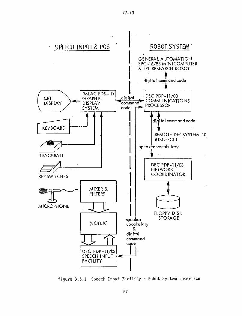
system (figure 11) is a breadboard intended to provide a
tool for testing various approaches to problem-solving and
autonomous operation [LEWI 77] The major components of the
integrated system include perception(vision) path planning
locomotion manipulation simulation and control The
processors which perform these operations (figure 12)
include a remote Decsystem 10 a General Automation
SPC-1685 minicomputer an IMLAC PDS-ID graphics display
system and three DEC PDP-1103 microcomputers One
PDP-103 with a floppy disk drive serves as the
microcomputer network coordinator The second PDP-1103 is
used as a communications controller for the distributed
system and the third is used for the speech inputoutput
interface The voice input system is composed of both
hardware and software processing which make up the isolated
word recognizer Voice output is accomplished through use
of a VOTRAX VS-64 Audio Response System under control of
the third microcomputer This processor configuration was
chosen to allow flexibility in the robotics research
program
The speech inputoutput system presented can be used to
control the execution of a task oriented system The
application presented in this work is directed at providing
a user with the capability to question direct and simulate
the performance of the JPL robot system and its individual
3
77-73
figure 11 JPL Research Robot
4
figure 12JPL Robot System-
Processor Organization
STORAGEA
SPEHDEC PROCESSING
HARDWARE
77-73
IMLAC PDS-1DGRAPHIC REMOTEDISPLAY DECSYSTEM-10SYSTEM (UJSC-ECL)
DEC PDP-1103 COMMUNICATIONS PROCESSOR
DEC PDP-1 103 IGENERAL NETWORK AUTOMATION COORDINATOR SPC-1685
PDP-1 103 JPL SPEECH RESEARCHINUUPTROBOT INPUTOUTPUTFACILITY
5
77-73
subsystems The IMLAC graphics system is used to display
status information predicted positions of vehicle
components and terrain maps of the environment The user
through voice input will be able to specify the execution
of local graphics transformations upon the CRT image or
select a new area of interest for which a display can be
created For each subsystem status display the user can
query the data base for its specific state of activity For
example information may be requested regarding the relative
positions of obstacles lying within the planned path of the
vehicle or the user may call up an additional display
routine of the arm to evaluate the performance of a set of
wrist joint positions upon the grasping of an irregularly
shaped object When viewing a representation of the robot
vehicle and its surroundings the user may desire to
simulate planned actions (eg vehicle movement arm
motion) before their actual execution Critical system
states are automatically communicated to the user through
voice output This type of man-machine interaction readily
lends itself to the application of voice communication
This report begins with a brief presentation in chapter
2 of the mechanisms involved in human speech generation and
recognition The bulk of the research however is directed
at the work involved in the development of the speech inputshy
facility and is addressed in chapter 3 The voice output
6
77-73
system is presented in chapter 4
7
77-73
CHAPTER 2 - HUMAN MECHANISMS FOR SPEECH GENERATIONAND RECOGNITION
Before beginning a design of the automatic speech
recognition system it was helpful to first gain an
understanding of the mechanisms involved in human speech
production and recognition These mechanisms are
qualitatively presented with attention given to their
effects upon sound wave properties
21 Human Speech Production
Man generates sound by causing air molecules to
collide Air is drawn into the lungs and expelled through
the trachea into the throat cavity by means of the
respiratory muscles Near the top of the trachea resides
two lips of ligament and muscle the vocal cords Voiced
sounds are produced by the flow of air forcing oscillation
of the vocal cords The mass of the cords their tension
and the air pressure upon them determine the frequency of
vibration
Other components of the human speech facility which
affect the accoustic properties of the generated sounds
include the vocal tract nasal cavity and mouth The vocal
tract proper is a deformable tube of non-uniform
8
77-73
cross-sectional area whose configuration influences the
frequencies comprising the speech waveform The movements
of the lips tongue and jaw change the size of the opening
from which the air passes this affects the nature of the
signal produced as does the persons rate of speaking
emotional state and the context of the utterance [GLEN 75]
Human speech is actually continuous in nature The
properties of the speech wave reflect the time dependent
changes in the vocal apparatus Despite this
characteristic words can be represented as strings of
discrete linguistic elements called phonemes For example
the word boiling is described phonetically (in [ELOV 76])
by the VOTRAX [VOTR 00] string BOAY13LING
Standard American English contains 38 distinct phonemes
[ATMA 76] Phonemes can be divided into the categories
pure vowels semi-vowels diphthongs fricatives nasals
plosives and laterals
Pure vowels are normally produced by a constant vocal
cord excitation of the vocal tract The tract and mouth
configuration is relatively stable during the voicing of the
sound The sound is mostly radiated through the mouth
some radiation of the vocal tract walls also occurs (The
mouth is not as stable in the production of semi-vowels
such as w and y) Diphthongs are transitions from one
pure vowel to another Fricatives (eg v in vote
9
77-73
z in zoo h in he ) are produced from noise
excitation of the vocal tract such as the air flow that
results when the tongue is placed behind the teeth Nasals
(eg m in me n in no) result from vocal cord
excitation coupled with closure at the front of the vocal
tract by the lips or tongue Plosives result from explosive
bursts of air (eg p in pack k in keep t in
tent) The I sound is an example of a lateral
22 Human Speech Recognition
The ear is conventionally divided into three
acousto-mechanical components the outer ear the middle
ear and the inner ear The outer ear is composed of the
pinria (the large appendage on the side of the head commonly
called the ear) the ear canal and the tympanic
membrane(eardrum) The outer ear collects the rapid
fluctuations in air pressure characterizing the sound wave
leads it down the ear canal and sets the tympanic membrane
into vibration
The middle ear cavity is filled with air and the three
ossicular bones the malleus incus and stapes (informally
called the hammer anvil and stirrup respectively) The
function of the middle ear is to provide an impedance
transformatibn from the air medium of the outer ear to the
fluid medium of the inner ear This amplification of the
10
77-73
pressure applied to the stapes footplate from the tympanic
membrane is on the order of 151 Middle ear muscles (the
tensor tympani and the stapedius) provide protection for the
inner ear from excessive sound intensities by restricting
the movement of the ossicles [LITT 65] In adjusting the
sensitivity of the ear these muscles also provide a
low-pass filter characteristic [FLAN 65]
The inner ear is composed of the liquid filled cochlea
and vestibular apparatus and the auditory nerve
terminations The tympanic membrane as it vibrates exerts
pressure on the stapes footplate which is seated on the
cochlea This provides a volume displacement of the
cochlear fluid proportional to the motion -of the tympanic
membrane The amplitude and phase response of a given
membrane point along the- cochlea is-similar to that of a
relatively broad bandpass filter Mechanical motion is
converted into neural activity in the organ of Corti
The ear appears to make a crude frequency analysis at
an early stage in its processing Mechanisms in the middle
ear and inner ear seem to measure -properties of peak
amplitude pitch and relative intensity of the component
sound waves [FLAN 65 WHIT 76b] For these reasons a
frequency domain representation of speech information
appears justified and advantageous
11
77-73
CHAPTER 3 - THE AUTOMATIC ISOLATED WORD RECOGNITION SYSTEM
Success has been demonstrated in the recognition of
isolated words from a fixed vocabulary accuracy rates in
excess of 97 per cent have been reported for 50-200 word
vocabularies [BOBR 68 ITAK 75 MCDO 00 VICE 69] The two
areas of continuous speech recognition and speech
understanding exhibit more difficult problems and are often
confused with the area of isolated speech recognition To
clarify the use of these terms the following definitions
are given
ISOLATED SPEECH RECOGNITION- Therecognition of single words in which aminimum period of silence is requiredbetween adjacent words (usually at leastone tenth second) to insure that theadjacent words do not confuse theanalysis of the current utterance
CONTINUOUS SPEECH RECOGNITION- Therecognition of words spoken at a normalpace without unnatural pauses betweenwords to aid in end-point detection
SPEECH UNDERSTANDING- The recognitionand understanding of words or phrasesspoken in a natural manner in whichsemantic or pragmatic information isutilized
12
77-73
31 General Description
In the design of the automatic speech recognizer
process of this project many decisions had to be made
affecting its overall structure and performance The
decisions arrived at reflect the intended use of the system
in addition to its possible evolution The following speech
recognition system properties characterize its robotics
control application
- single word (often mono-syllabic) or
short phrase commands
- medium sized extensible vocabulary (100 words)
- high accuracy desirable (99 per cent)
- close to real-time operation
- cooperative user environment
- single speaker used per session different sessionmay be directed bya different speaker
-must execute ona DEC PDP-103 microcomputer
- flexible software design and interface
- low cost
Throughout the design of the recognizer these
specifications were followed to produce the needed
end-product It should be stressed that this work was
directed at the previously outlined application and not at
the realization of a general purpose speaker-independent
large Vocabulary speech understanding system The
13
77-73
development of this low-cost microprocessor process was
attainable as a consequence of its task specific nature
The single wQrd recognition -design constraint enabled
the system to be developed as an isolated word recognizer
This decision reduced the difficulty of word boundary
detection found in continuous speech and in speech
understanding This choice also resulted in an easier
attainment of a high accuracy rate in near real-time
The medium sized vocabulary property made necessary the
development of data compression and pattern comparison
operations that would permit the DEC PDP-11 microprocessor
to quickly access and process the speech data As a
vocabulary increases in size the opportunity for one word
to be confused with another becomes greater Most speech
recognition systems use some form of high-level linguistic
cr semantic analysis to achieve an adequate rate of
recognition [HATO 74] A tree structured vocabulary for
this isolated word recognizer was developed to provide near
real-time accurate recognition This use of syntactic
constraints is discussed in section 34
The recognition software has been written in DEC PDP-11
assembly language [DEC 76] for overall system efficiency A
flexible program architecture was realized through use of
nighly structured modularized routines Firm routine
14
77-73
interfaces localize component responsibilities and permit
individual subroutine modifications without side effects
The isolated word recognition system can be segmented
into its three main tunctions feature extraction data
compressionnormalization and utterance
comparisonclassification (figure 311) During feature
extraction the input voice signal is sampled and its
representative properties measured This results in the
collection of large amounts of speech data To permit
conservation of storage and processing speed the incoming
data is compressed and normalized Utterance matching
techniques are used to identify the input pattern sample
The condensed input is compared to the stored
parameterization of each word in the vocabulary A decision
is made based upon the results of the comparisons
The choices made for the feature extraction data
compressionnormalization and utterance
comparisonclassification procedures for the JPL word
recognition system were based upon system characteristics
such as processor speed and instruction set as well as
vocabulary type and structure The three sets of recogniton
routines selected were required to be compatible with each
other
15
77-73
figure 311Isolated Word Recognition System Components
ROVER
~~ FEATU RE EXTRACTION
TIME
DATA(1 COMPRESSION 1 NORMALIZATION
ARM UTTERANCE COMPARISON
STATU 5 CLASSIFICATION
(ROVER)
16
77-73
32 Feature Extraction
Some form of preprocessing is required to represent the
speech signal in a reasonable manner If the signal
amplitude was sampled and digitized every 50 microseconds
and one byte was required per value 20000 bytes of memory
would be needed to record an utterance one second in
duration Real-time processing of this amount of data would
be difficult and word prototypes would consume too much
storage to be kept in fast memory
Mostexisting word recognition systems use one of two
general preprocessing techniques bandpass filtering or
linear predictive coding Bandpass filtering segments the
speech wave in 2 to 36 (usually non-overlapping) frequency
bands it is often accomplished through hardware When the
frequency segmentation corresponds to the fundamental
frequencies found in human speech production it is called
formant analysis The outputs of these bandpass filters are
then examined through hardware or software means over a
given time interval Examples of such properties measured
are zero-crossings average amplitude peak-to-peak
amplitude total energy average energy and power
A discrete word recognition system developed at
McDonnell-Douglas uses a mini-computer to process amplitude
information from three frequency bands in attempting to
17
77-73
represent utterances as a series of phonemes [MCDO 00]
Neroth [NERO 72] uses hardware to generate analog signals
proportional to zero-crossing rates and average energy for
two frequency bands Snell [SNEL 75] has proposed to use
the same approach and algorithms in a slower more limited
recognition system targeted for implementation on a
microprocessor Vicens [VICE 69] also uses amplitude and
zero-crossing measures but upon a three bandpass filtered
speech system Lowerre [LOWE 76] uses peak-to-peak
amplitude and zero-crossing values in a five band speech
understanding system Itahashi uses a different type of
measure ratios of the output powers of four bands to
determine phoneme classifications (ITAH 73] Systems by
Gold [GOLD 66] and Bobrow and Klatt [BOBR 68] use 16 and 19
filters respectively to analyze the speech spectrum
Linear predictive coding (LPC) implemented in hardware
or software similarly analyzes the frequency components of
speech More computation is required than in the bandpass
filtering amplitudezero-crossing techniques but greater
data reduction is realized The output of a LPC routine can
be in the form of LPC coefficients and predictive errors
LPC coefficients are used in generating an acoustic tube
model of speech in order to identify formant peaks The
linear predictive residual is defined as the error which
remains when a linear predictive filter is applied to a time
18
77-73
series representation of speech [WHIT 76b] It has been
used to provide an efficient means to measure the similarity
of two utterances [ITAK 75] Such values can be thought of
as being similar to those provided by Fourier analysis or
outputs from a programmable bank of narrow bandpass filters
(Makhoul has documented a system in which 36 filters were
used [MAKH 71])
Atal Rabiner and Sambur [ATAL 76 RABI 76 SAMB 75]
use zero-crossing Fate speech energy autocorrelation
coefficients of adjacent speech samples in addition to LPC
coefficients and the energy of LPC prediction error to
determine speech classifications Dixon and Silverman [DIXO
75 SILV 74] through PLI software executing on an IBM
36091 perform a discrete Fourier transform (DFT) in
addition to their LPC calculation upon digitally recorded
input Itakura [ITAK 751 uses a minimum prediction residual
rule based upon a time pattern of LPC coefficients to
recognize isolated words Makhoul [MAKH 73] performs his
spectral analysis of speech by the autocorrelation -method of
linear prediction to minimize oversensitivity to high
pitched speech components
Otherfeature extraction techniques used have included
calculation of -pitch periods[ATAL 72 REDD67- WELC 73]
software implementation of LPC or zero-crossing measures
using speech waves which have been digitized and stored on
19
77-73
tape [PAUL 70 WASS 75 WOLF 76] hardware phase-lock loop
tracking of fundamenta1 frequencies [HONG 76] and
axis-crossing detection of frequency modulated speech waves
[PETE 51]
The speed and capability of the LSI-ll microprocessor
and the development cost of hardware preprocessors
constrained the choice of a feature extraction method for
the JPL sytem Linear predictive coding software could
have beeh implemented on the LSI-11 microprocessor- however
-its execution would not permit the word recognition-system
to- operatein close to real-time LPC hardwarewould be
very expensive to develop no source wasfbuhnd whidh had
knowledgeof ra LPC hardware package A flexiblefeature
Z extraction processor based upon a series of barfdpampss fVilters
wasiselectAd
Experience has shown that reliable isolated word
recognition systems can be built using information derived
from three frequency bands adjusted so that they approximate
the first three formant ranges of human speech The formant
frequencies of speech are the frequencies characterized by
strong resonances and energy peaks [RICE 76] For the
JPL system the frequency ranges chosen for
-incorporation into the feature extractorwete the ranges
200-750 -800-2250 23M-2920 and 3000-4000 6ybles per
second - -These values roughly represent thefirst three
20
77-73
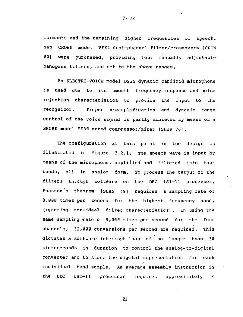
formants and the remaining higher frequencies of speech
Two CROWN model VFX2 dual-phannel filtercrossovers [CROW
00] were purchased providing four manually adjustable
bandpass filters and set to the above ranges
An ELECTRO-VOICE model DS35 dynamic cardioid microphone
is used due to its smooth frequency response and noise
rejection characteristics to provide the input to the
recognizer Proper preamplification and dynamic range
control of the voice signal is partly achieved by means of a
SHURE model SE30 gated compressormixer [SHUR 76]
The configuration at this point in the design is
illustrated in figure 321 The speech wave is input by
means of the microphone amplified and filtered into four
bands all in analog form To process the output of the
filters through software on the DEC LSI-11 processor
Shannons theorem [SHAN 49] requires a sampling rate of
8000 times per second for the highest frequency band
(ignoring non-ideal filter characteristics) In using the
same sampling rate of 8000 times per second for the four
channels 32000 conversions per second are required This
dictates a software interrupt loop of no longer than 30
microseconds in duration to control the analog-to-digital
converter and to store the dig-ital representation for each
individual band sample An average assembly instruction in
the DEC LSI-1l processor requires approximately 8
21
77-73
GATED COMPRESSORMIXER
DUAL-CHANNEL DUAL-CHANNEL- FILTER FILTERCROSSOVER CROSSOVER
BAND0 BAND I BAND2 BAND3
DEC PDP-1103 MICROCOMPUTER
figure 321Software Supervised Feature Extraction
22
77-73
microseconds to execute this sets the maximum length of
the loop at four instructions Software data collection at
these rates is impossible on the LSI-11 microprocessor
(Note additional processor time would have been required
to process the data which would fill nearly 32K words of
memory per second)
The solution to these data collection- and compression
problems necessitated the use of a hardware feature
extractor Of foremost importance in its design was
flexibility in features measured and the ease at which it
would interact with the supporting LSI-ll recognition
software A variety of measurements have been Used by
others in their designs of word recognition systems (and
have previously been noted) Some have used zero-crossing
measures together with amplitude or energy values To allow
flexibility in the -choice of utterance parameterizations
the initial JPL system uses a processor resettable
zero-crossing counter and amplitude integrator for each of
the four bands By incorporating processor controllable
counters and integrators the software can specify the
period of time for which zero-crossings will be accumulated
and energy averaged The initial window length chosen was
ten milliseconds Longer periods tend to provide less
information regarding local properties of the speech signal
(eg peaks) [REDD 76] while shorter periods yield
23
77-73bull-1
insufficient data reduction
6 eafsiy measured property of aspeech sign-al used by
NerOth - iNERd 72f -in his word recognition system and by
Mcfoell-ugt [MCDO 001 lin their system is the total
Ldrdofatib dt etraneamp 3ThiS information is avaIlable in
the JPL system but it is not included in the final
parameterization of the word This decision was made in the
attempt to keep such voicing characteristics from affecting
the recognition strategy If this property were to be used
the rate at which a word was spoken (ie the intraword
pacing) would exert an influence upon the later comparison
measures
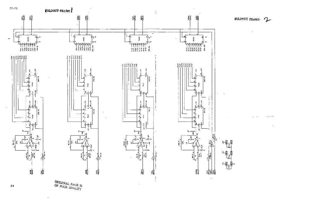
The VOice Feature EXtraction (VOFEX) hardware consists
of four identical pairs of circuits (details of these
circuits are presented in appendix A) Each pair is
connected to a different bandpass filter output and is
comprised of a zero-crossing circuit and an independent
energy averaging circuit (figure 322) The zero-crossing
values provide frequency distribution information in each
range over the length of the word The energy measures give
an indication of energy concentration between the four bands
during a given utterance segment This results in a
two-dimensional word description
24
77-73
figure 322Hardware (VOFEX) Supervised Feature Extraction
GATEDCOMPRESSORMIXER
FILTER FILTERCROSSOVER CROSSOVER
BAND 0 RAND I BAND 2 BAND 3 cLERB u JAT
VOICE FEATURE CLEARACCUMULATEEXTRACTORENRIS (VOFEX) RESETCOUNT
ZERO-CROSSING 11 SIGNALS
ANALOG I ENERGY IVALUES DIGITAL ZERO-CROSSING
BANDS 0123 COUNT FOR BAND
DEC PDP-1103 j1
MICROCOMPUTER
25
77-73
The four bandpass filters used each have an 18 db per
octave maximum rolloff rate In simpler terms frequencies
above and below the band settings - ar-eo -not- attenuated
completely but are reduced in proportion to their distances
from the filter settings As a result of this filter
property in actual performance the bandpass filters could
not provide a means for gathering data completely from
within one formant range The speech waves data collected
was somewhat dependent upon the higher amplitudes of the
lower frequencies At later stages in the feature
extraction implementation the initial filter settings were
therefore adjusted to provide for narrower bandpasses This
adjustment was intended to help in the achievement of better
formant independent data collection This partial solution
to this problem also entailed the raising of the hysteresis
of zero-crossing detection circuit in the VOFEX A further
solution would involve the purchasing or building of higher
order bandpass filters (The final filter settings are
listed in appendix B)
The zero-crossing counters are individually read and
reset by the LSI-11 microprocessor by means of a DEC DRV-11
parallel interface board The average energies are applied
as inputs to an ADAC Corporation analog-to-digital converter
board [ADAC 00] under software control of the LSI-11
microprocessor They are reset(cleared) by means of the
26
77-73
parallel interface The A-to-D converter cannot become
saturated by long windowing periods or large signal values
due to-input scaling through means of the compressormixer
and protective circuits in the VOFEX The sampling of the
VOFEX outputs and the triggering of the A-to-D converter
are coordinated and controlled by an MDB KW11P programmable
clock board in the LSI-11 microcomputer
The hardware was designed to provide raw zero-crossing
counts and non-normalized energy measures In proceeding in
this manner the recognition system is not bound to their
output representation Different functions or measures can
be developed to evaluate and represent zero-crossing
information and can be implemented in software This
flexibilty is also present in the measureenergy domain
This minimizing of the responsibility of the hardware helped
keep the VOFEX construction costs low The VOFEX hardware
design specifically its use of digital values for
zero-crossing counts and windowing period controls differs
from the more constrained feature extraction methods
previously used
33 Data Compression and Normalization
The feature extraction process passes along to the
remainder of the word recognition system eight words of
information (the zero-crossing count and the average energy
27
77-73
for each of the four frequency bands) every ten
milliseconds Using a duration estimate of one second per
utterance 800 words of storage would be required to hold a
description of each word in the vocabulary if they were to
be represented in the data form received from the VOFEX A
vocabulary of 100 words would take up approximately four
times the storage available in the speech LSI-l1
microcomputer The form of the parameterization of a voiced
utterance also has an effect upon the design and performance
of the comparisonclassification process A decision as to
the identity of a spoken word is made on the basis of how it
best matches a word prototype in the vocabulary The
performance of such a decision mechanism is determined by
the complexity of the comparison operation and by the
number of comparisons it is required to make A comparison
function which evaluates the similarity between two 800 word
utterance parameterizations will be more complex and will
require more execution time than one being used upon a more
compact speech representation The processes of reducing
this volume of descriptive data and of representing word
parameterizations to aid in the later decision operations
are called data compression and data normalization
respectively
28
77-73
In the development of real-time or near real-time word
recognition systems data compression techniques sacrifice
the information content of the speech signal for processing
speed and ease of representation Dixon and Silverman [DIXO
75 SILV 74] follow a philosophy of minimal loss of
information and do not make this compromise For a
microprocessor based system data must be reduced and be
compactly conveniently represented
In recognition systems that utilize linear predictive
coding methods for data collection data compression is
attained at the same time as feature extraction The output
of such feature extractors are LPC coefficients and residual
errors In many such systems this resultant information is
used to segment the time series representation of speech
into probable phoneme groups (eg [BEEK 00 WOLF 76])
Most speech input systems that are used in the
recognition of connected speech must in some way
differentiate periods of silence from periods of unvoiced
speech It is by this decision that such systems can then
direct themselves at the recognition of individual words
often by identifying boundaries between voiced and unvoiced
segments Atal and Rabiner [ATAL 76] calculate the means
and standard deviations of selected speech properties to
tune this decision section of their recognition system
Connected speech recognition systems require feature
29
77-73
extraction processes which will supply sufficient
information to enable these voiced-unvoiced-silence
decisions to be made
In an isolated word recognition system the critical
silence- unvoiced decision does not exist Periods of
silence can be identified by means of the length of an
unvoiced segment Along with this design simplification
accompanies the requirement that individual commands spoken
to an isolated word recognizer be separated by a minimum
period of silence The resulting speech input will sound
unnatural due to this pacing This presents no problem in
the use of this voice input system the JPL robotics
control vocabulary is comprised of isolated command words
The command vocabulary can be extended to include short
phrases as long as the interword silence periods are
minimized during their voicings
Gold [GOLD 66] points out that speech data does not fit
into predetermined formats such as a Gaussian model of a
proper dimension Martin [MART 76] adds that no general
mathematical theory exists which can preselect the
information bearing portions of the speech data The design
of a recogniton system must incorporate heuristic and ad hoc
strategies to enable its proper operation It is in the
data compression and normalization stages that many
recognition systems whose feature extraction processes
30
77-73
appear similar diverge in order to achieve their respective
final parameterizations
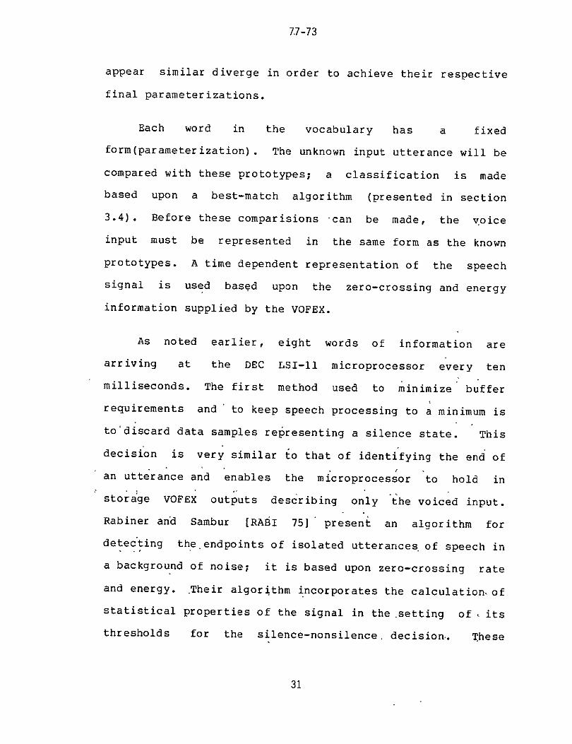
Each word in the vocabulary has a fixed
form(parameterization) The unknown input utterance will be
compared with these prototypes a classification is made
based upon a best-match algorithm (presented in section
34) Before these comparisions can be made the voice
input must be represented in the same form as the known
prototypes A time dependent representation of the speech
signal is used based upon the zero-crossing and energy
information supplied by the VOFEX
As noted earlier eight words of information are
arriving at the DEC LSI-11 microprocessor every ten
milliseconds The first method used to minimize buffer
requirements and to keep speech processing to a minimum is
todiscard data samples representing a silence state This
decision is very similar to that of identifying the end of
an utterance and enables the microprocessor to hold in
storage VOFEX outputs describing only the voiced input
Rabiner and Sambur [RABI 75] present an foralgorithm
detecting theendpoints of isolated utterances of speech in
a background of noise it is based upon zero-crossing rate
and energy Their algorithm incorporates the calculationof
statistical properties of the signal in the setting of its
thresholds for the silence-nonsilence decision These
31
77-73
computations require processor time in the attempt to
achieve this speaker independent self-adapting
characteristic
The properties made use of in the decision algorithm of
the JPL system are similar to those used by Rabiner and
Sambur It does not however use statistical measures in its
operation The beneficial self-adapting nature of their
procedure is offset by the complexity of its implementation
on the LSI-ll microprocessor and by the application of this
system Speaker dependent characteristics that will
influence the silence decision can be stored with that
speakers vocabulary file (see appendix D) in the form of
threshold parameters for the recognition system By
proceeding in this manner minimum values can be
assigned(preset) for detecting the zero-crossing rates and
energy levels for the four frequency bands which together
represent speech The only learning period required in
the JPL system for the identification of a silence state
is ten milliseconds at the beginning of the recognizer
operation to measure and record room noise levels
In another recognition system Paul [PAUL 70] uses only
amplitude information in his endpoint decisions In
environments where a high signal-to-noise ratio exists an
effective algorithm can be developed based upon energy
(level) values alone specifically in the lower frequency
32
7773
range In less ideal environments zero-crossing
information can help in distinguishing weak fricative sounds
from background noise The threshold values used in-the
JPL system were set experimentally after sampling the
VOFEX outputs for silence segments Inevaluating the
performance of the word detection routine it was found that
the zero-crossing information was not consistent enough in
character to be used in the utterance start-stop algorithm
The bandpass filters were not providing sufficient
attenuation of frequencies outside their ranges and
therefore unwanted amplitudes were affecting the detection
of zero-crossings at unvoiced-voiced boundaries The JPL
endpoint algorithm was modified to utilize only the
amplitude information provided by the four frequency bands
in its decision making
The start and end of an utterance is not abrupt
speech is continuous not discrete in nature Due to the
presence of noise and unvoiced segments a recognition
system cannot look at a single ten millisecond window and
make a decision as to the location of an endpoint A more
reasonable afd accurate algorithm would require a certain
period of non-silence to indicate the start of a word and
thereafter a definite period of silence would signify the
end of the word Initially these values were chosen to be
-four ahd- five window lengths (40 and 50 milliseconds)
33
77-73
respectively One needs such durations to insure that a
burst of noise does not trigger the recognizer and that an
unvoiced segment within an utterance does- -not terminate
prematurely the collection of data
As the result of implementation considerations the
word detection algorithm used requires only one window of
non-silence to indicate the start of a word False starts
are detected and discarded by imposing a minimum utterance
length upon the word This length was initially set at
eight window lengths (80 milliseconds) and extended after
process evaluation (see appendix B)
The utterance is represented by the data collected from
the beginning of the non-silence detection period until the
beginning of the silence detection period This makes
maximum use of early low-level word voicings while tending
to ignore less important trailing sound Figure 331
illustrates the initial representation of an utterance by
the recognition routines
A maximum utterance duration is enforced for
implementation considerations (buffer size) and as a system
precaution The system is initially set to halt utterance
data collection three seconds after the beginning of speech
is detected This can be easily changed without affecting
the operation of the recognizer software and places little
34
BAND 0OZC
BAND ZcI I BAND 2ZC
BAND 3ZC BANDO0ENERGY BAND I ENERGY
BAND 2 ENERGY___
BND3 ENERGY
TIME (10 - 3 sec)
WINDOW TYPE
STARTtND DETECT
UTTERANCE LOCATIONshy
[J J 3~ IZEIFIiiiz iL
I~
Z Z[~]IIJ____________
IA I 7IZL(ZI_ _ _ _ _
I I iIIZ 270 280 290 300 310 320 330 340 350 360 370 380 390 400 410 420 430
s s s i n nlnl nt s1 nl sln s ss i s n
STARE D W Sshy
WORD ISCOMPOSED OFUIl RANC[ OAIA FORTHESEWINDOWS
WINDOW TYPE s - SILENCE
n NON-SILENCE
figure 331 Utterance Location Based Upon Non-silence Detection
77-73
constraint upon the composition or vocalization of the
vocabulary This value would need to be altered to permit
the addition of longer input words to the vocabulary or the
recognition of inputs from a very slow speaking operator
(Figure 332 represents the detailed utterance detection
procedure used in the JPL system)
Once the data for an utterance has been collected data
compression and normalization routines must be applied to
achieve a representation in the same form as the vocabulary
prototypes The parameterized form chosen for the JPL
recognition system was influenced by earlier speech
recognition approaches but was principally developed as a
nesult of the types of signal values being measured
Bobrow and Klatt [BOBR 68] in their isolated word
recognition work use property extractors to evaluate
speech features and then apply functions based upon these
extractors to reduce the range of their values They chose
to represent the speech input on the word level Some
systems which have been developed use a phoneme level
representation of speech This requires additional
collection and processing of information to segment the word
into the phoneme groups Phoneme segmentation decisions are
subject to considerable error phoneme connecting rules are
used in some systems to aid in error correction [ITAH 73]
Phoneme segmentation algorithms are cnaracteristic of
36
77-73 QRIGINIAL PAGE IS
OF POOR QUALTY
START Jfigure 332 Utterance Detection Procedure
ENDWRD gt-J TRUE PERIODMIN SILENCEFOR END
J= 0 WORD DETECT
-- FA LSEI
BEGWRD I- 0
ENDWRD 0 CCLEONGTIOSST0OF
CLENGTH CLENGTH -
RENDWRD
J+IWINDOW RU
MIN UTTEANC
CLSSII-IO
NON-SILENC TRUCEDUA
CLE hGTH~t- LENGTH-TRUE CNTHCo
WINDOWEDWD+1IETT ENDWRDGTUMB0
BEWD JIPTUTTERANCEDTCASFCTO
D--TAj FO+ 1 PTROCEDURES
37 LIO NMBERTT~WINDOW NDWRD+ 1 CDE
AP7L
77-73
connected speech recognition and speech understanding
systems Such an approach is not needed in the JPL
system because of the isolated word nature of the input and
-the -proportion -shy ofshy mono-syllabic utterances in the
vocabulary
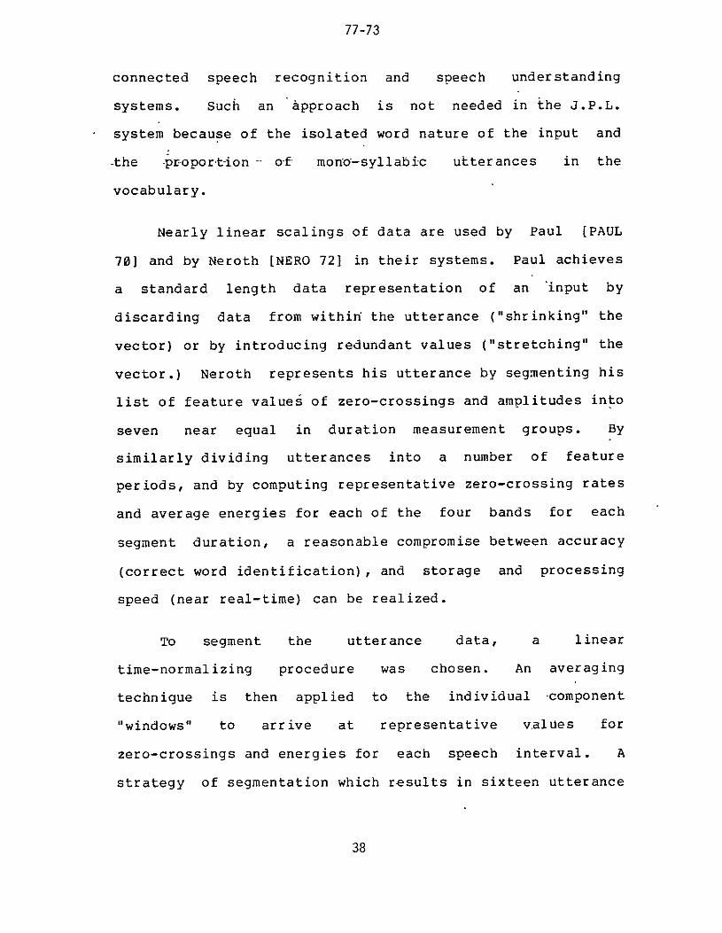
Nearly linear scalings of data are used by Paul [PAUL
70] and by Neroth [NERO 72] in their systems Paul achieves
a standard length data representation of an input by
discarding data from within the utterance (shrinking the
vector) or by introducing redundant values (stretching the
vector) Neroth represents his utterance by segmenting his
list of feature values of zero-crossings and amplitudes into
seven near equal in duration measurement groups By
similarly dividing utterances into a number of feature
periods and by computing representative zero-crossing rates
and average energies for each of the four bands for each
segment duration a reasonable compromise between accuracy
(correct word identification) and storage and processing
speed (near real-time) can be realized
To segment the utterance data a linear
time-normalizing procedure was chosen An averaging
technique is then applied to the individual component
windows to arrive at representative values for
zero-crossings and energies for each speech interval A
strategy of segmentation which results in sixteen utterance
38
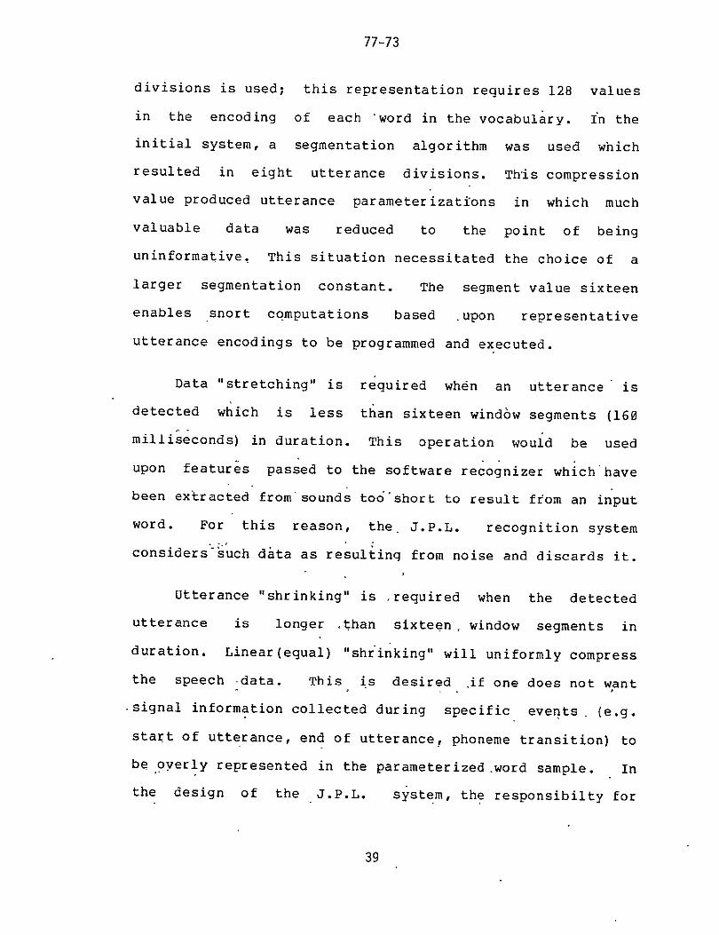
77-73
divisions is used this representation requires 128 values
in the encoding of each word in the vocabulary fn the
initial system a segmentation algorithm was used which
resulted in eight utterance divisions This compression
value produced utterance parameterizations in which much
valuable data was reduced to the point of being
uninformative This situation necessitated the choice of a
larger segmentation constant The segment value sixteen
enables snort computations based upon representative
utterance encodings to be programmed and executed
Data stretching is required when an utterance is
detected which is less than sixteen window segments (160
milliseconds) in duration This operation would be used
upon features passed to the software recognizer which have
been extracted from sounds tooshort to result from an input
word For this reason the JPL recognition system
considerssuch data as resulting from noise and discards it
Utterance shrinking is required when the detected
utterance is longer ithan sixteen window segments in
duration Linear(equal) shrinking will uniformly compress
the speech -data This is desired ifone does not want
signal information collected during specific events (eg
start of utterance end of utterance phoneme transition) to
be overly represented in the parameterized word sample In
the design of the JPL system the responsibilty for
39
77-73
stressing such features lies in the
comparisonclassification routines The output of the data
compressionnormalization section is a uniform speech sample
which provides the opportunity to later locally test and
implement a variety of decision methods
The following segmentation algorithm is used by Neroth
to calculate the number of window samples to incorporate
together for each of his normalized utterance sections
is the length of the utterance in units of windows N is
the number of sections that the utterance is to be segmented
into which will be refered to as the segmentation number
the value seven for N His ith section isNeroth uses
composed by averaging the values of the K(i-l)+1 K(i-l)+2
K(i-l)+3 K(i) data windows for i=l 2 3 N
K(i) = K(i-l) + s + r forUi=l 2 3 N where
K(O) = 0 by definition
s = LLNJ
r = 1 if L-(sN) gt= i r = 0 otherwise
close inspection of this segmentation algorithm will show
that its non-linearity causes the parametric representation
of the utterance to stress properties detected near its end
For example if L=18 the following divisions are computed
(windows are labeled sequentially by their number vertical
40
L
77-73
bars illustrate segmentation points)
I 1 2 3 I 4 5 6 j 7 8 9 I 10 11 12 1 13 14 I 15 16 1 17 18
A more uniform segmentation would appear as
I12 3 I 4 5 I 6 7 8 I 9 10 1 11 1213 I 14 15 I 16 17 18 I
The following algorithm is proposed to accomplish it
Z(0) = 0
Z(i) = L((iL)N) +05] for i=l 2 3 N
The function name V is used instead of K to
differentiate this new algorithm from that used by Neroth
It is computationally simple and easily implemented through
assembly language instructions on the DEC LSI-11
microprocessor Both the K and Z segmentation methods
are approximations to the ideal routine which would use
equal utterance intervals of (LN) windows (These
approximations are valid for utterances of a reasonable
duration) The ideal method would necessitate the use of
non-integer length window sections and would require greater
processing complexity than either the K or Z method
The Z segmentation method is used in the
compressionnormalization procedure for the JPL speech
recognizer process
41
77-73
Using the Z method for calculating the sixteen time
sections of the utterance an averaging scheme can now be
applied to the zero-crossing and-energy data that descr-tbes
the set of windows comprising each segment Using a
speech utterance sample with a length (L) of 36 and a
segmentation number (N) equal to sixteen the following
segmentation is computed
I 01 02 l 03 04 05shy 06 07 I 08 09 I 10 11 I I 12 13 14 15 16 I 17 18 I
I 19 20 I 21 22 23 24 25 I 26 27 I 28 29 I I 30 31 32 1-33 34 I 35 36 1
The actual number of windows that comprise each segment for
the above example(L=36 N=16) is
2 for segments 13457891112131516 and3 for segments 261014
The following standardized vector V is achieved by
reducing the data by means of averaging the information
contained in each segment
I V() I V(2) I V(3) I I V(16) I
Formally the V vector is computed for a single set of
data at a time (eg the zero-crossings for band 0 the
energies for band 3 etc) there are eight sets of V
42
77-73
vectors (zero-crossings and energies for each of the four
ands) If we use D(j) to represent the data value of the
ith window for a specfic class of information i=l 2 3
L (utterance of length L) tfen V is calculated by
the following procedure
Z(i)
V(i) (i(Z(i)-Z(i-l))) D(k)
k=Z (i-l)+l
for i=l 2 3 N
and oy definition Z(O)=0
By using this method for each class of utterance
information the word vector form illustrated in figure
333 is achieved Notice that at this point in
compressionnormalization the utterance continues to be
represented by raw data If the classification process used
a decision system based solely upon the similarities of such
signal measures this form could be used to store the
vocabulary prototypes and to represent the unknown word
The properties of zero-crossing rate and average energy
were chosen to represent features descriptive of human
speech It is the relative zero-crossing values within a
given band that is representative of the evolution of the
principle trequency components Raw zero-crossing values
43
SEGMENTATION OF UTTERANCE WINDOWS (L= 18 and N =7)
BAND 0 ZC BAND I ZC
2 10
3 I1
3 10
5 8
4 7
5 8
5 7
6 9
5 12
4 11
2 15
6 14
2 13
2 14
0 14
0 12
I 8
2 8
BAND 2 ZC 18 19 18 19 21 24 28 27 23 20 18 19 20 26 26 24 22 21 BAND 3 ZC 28 31 32 38 40 40 36 35 40 40 38 37 35 35 35 32 31 - 34 BAND 0 ENERGY 210 250 261 288 401 381 411 401 382 370 298 312 313 350 371 360 214 203 BAND 1 ENERGY 401 441 390 370 301 271 282 308 425 470 507 515 513 488 512 550 552 540 BAND 2 ENERGY 1000 1012 1400 1311 1398 1251 1259 1201 1311 1517 1701 1880 1750 1670 1590 1409 1371 1308 BAND 3 ENERGY 201 247 244 301 399 390 381 383 390 371 347 344 351 330 290 271 277 241
BAND 0 ZC 2 4 5 4 3 1 -BAND I ZC 10 7 8 11 14 14 9 BAND 2 ZC 18 20 26 21 19 26 22 BAND 3 ZC 30 39 37 40 36 35 32 BAND 0 ENERGY 240 344 397 376 308 360 259 BAND I ENERGY 420 335 287 447 511 500 547 BAND 2 ENERGY 1070 1354 1237 1414 1777 1630 1362 BAND 3 ENERGY 230 350 384 380 347 310 263 0(5
COMPRESSED WORD VECTORS OF RAW DATA
figure 333 Compressed Word Vector Consisting of Raw Data
77-73
are not as compact or informative as are functions of these
rates that have been developed Niederjohn [NIED 75]
presents a variety of different techniques that have been
useful in extracting significant features from zero-crossing
data One such processing of zero-crossing information is
the calculation of the number of time intervals for which
zero-crossing rates are between two values In the JPL
system the representation of such time dependent
characteristics- is accomplished by ranking the utterance
intervals based upon their zero-crossing counts Four
separate rankings o-f zero-crossing values for the length of
the standardized utterance is used one ranking for each
band This is easily calculated by means of a sorting
procedure applied to the vector elements this method
requires less computation and software than many other
zero-crossing techniques In using this normalization
method upon the zero-crossing values averaged for a single
band (values are represented in the previously defined
vector VIh) the ranked zero-crossing measures are
represented in vector RZ RZ exhibits the following
element relationship
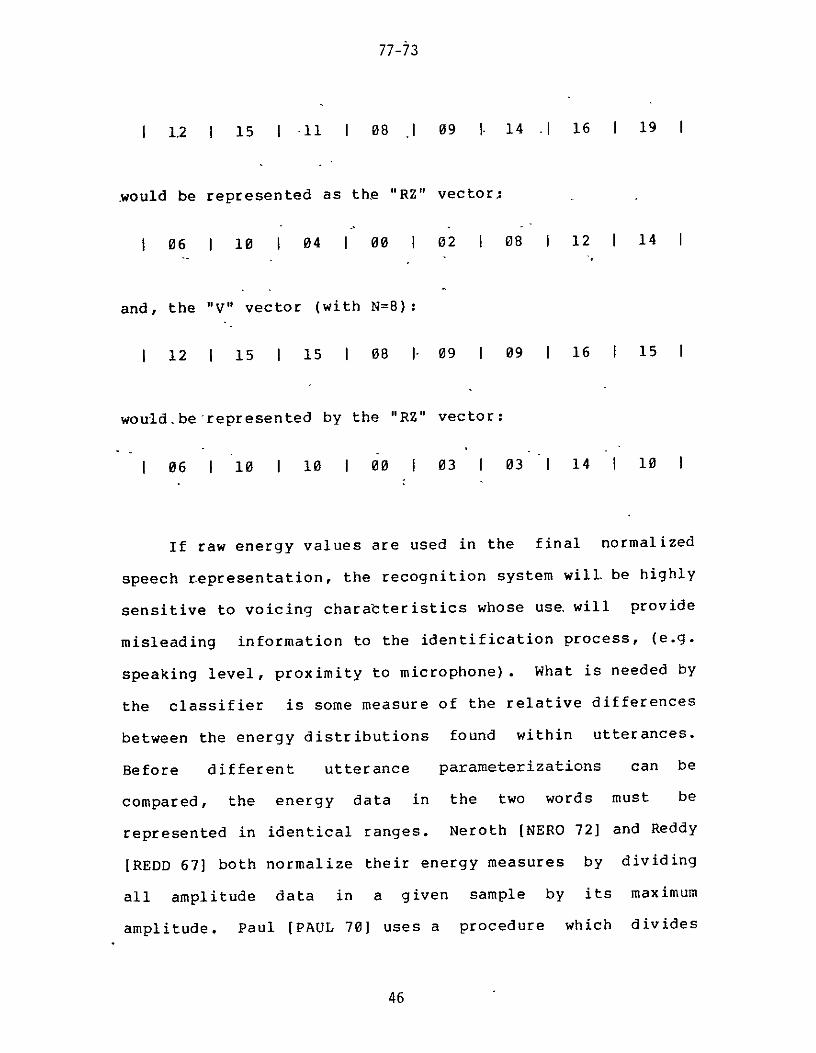
V ij ij=l 2 3 NRz(i) gt RZ(j) = V(i) gt V(j)
and RZ is obtained by reordering and averaging the values I 00 I 02 I 04 j 06 I 08 I 10 I I 2(N-l) i
For example the V vector (with N=8)
45
77-73
12 I 15 I -11 I 08 1 09 I- 14 1 16 19 I
would be represented as the RZ vector
06 I 10 I 04 I 00 I 02 I 08 I 12 14 I
and the V vector (with N=8)
12 I 15 I 15 I 08 I- 09 I 09 I 16 15 I
would-be represented by the RZ vector
06 I 10 I 10 I 00 I 03 I 03 I 14 10 I
If raw energy values are used in the final normalized
speech representation the recognition system will be highly
sensitive to voicing charabteristics whose use will provide
misleading information to the identification process (eg
speaking level proximity to microphone) What is needed by
some measure of the relative differencesthe classifier is
between the energy distributions found within utterances
Before different utterance parameterizations can be
in the two words must becompared the energy data
represented in identical ranges Neroth [NERO 72] and Reddy
[REDD 67] both normalize their energy measures by dividing
by its maximumall amplitude data in a given sample
amplitude Paul [PAUL 70] uses a procedure which divides
46
77-73 shy
his sampled amplitudes by their average amplitude value
All of these methods generate fractional results which must
be stored and carried along through the remainder of the
recogn-izer system Fractional arithmetic requires more
processing time than does integer The computational
capabilities available in the LSI-ll microcomputer are- very
limited it is for this reason that the algorithms used in
the JPL recognition system are designed for and
implemented with integer values
To normalize the 64 standardized energy measures for an
entire input utterance (sixteen measures for each of the
four bands) the data in each band is represented as an
offset from the minimum value scaled and then divided by
the range of energy values for the given band This method
yields an integer result of maximum significance for the
LSI-11 microprocessor word size (16 bits including sign)
The values calculated by this procedure should better
reflect changes in theamplitude measures than the algorithm
used by Reddy A disadvantage of this method is that it
will produce unreliable and misleading results for values
over a small range To guard against this occurrence the
amplification circuits in the VOFEX have been tuned to the
charact-eristic amplitudes of speech passed through each
bandpass filter to provide proper amplitude ranges The
procedure for generating the normalized energy vector EV
47
77-73
for a given band of the utterance from the V -standardized
raw energy vector is
MAXEN = maximum energy value of the N energy samplesin the utterance band
MINEN = minimum energy value of the N energy samplesin the utterance band
EV(i) = ((V(i) - MINEN) 32768) (MAXEN - MINEN + 1) for i=l 2 3 N
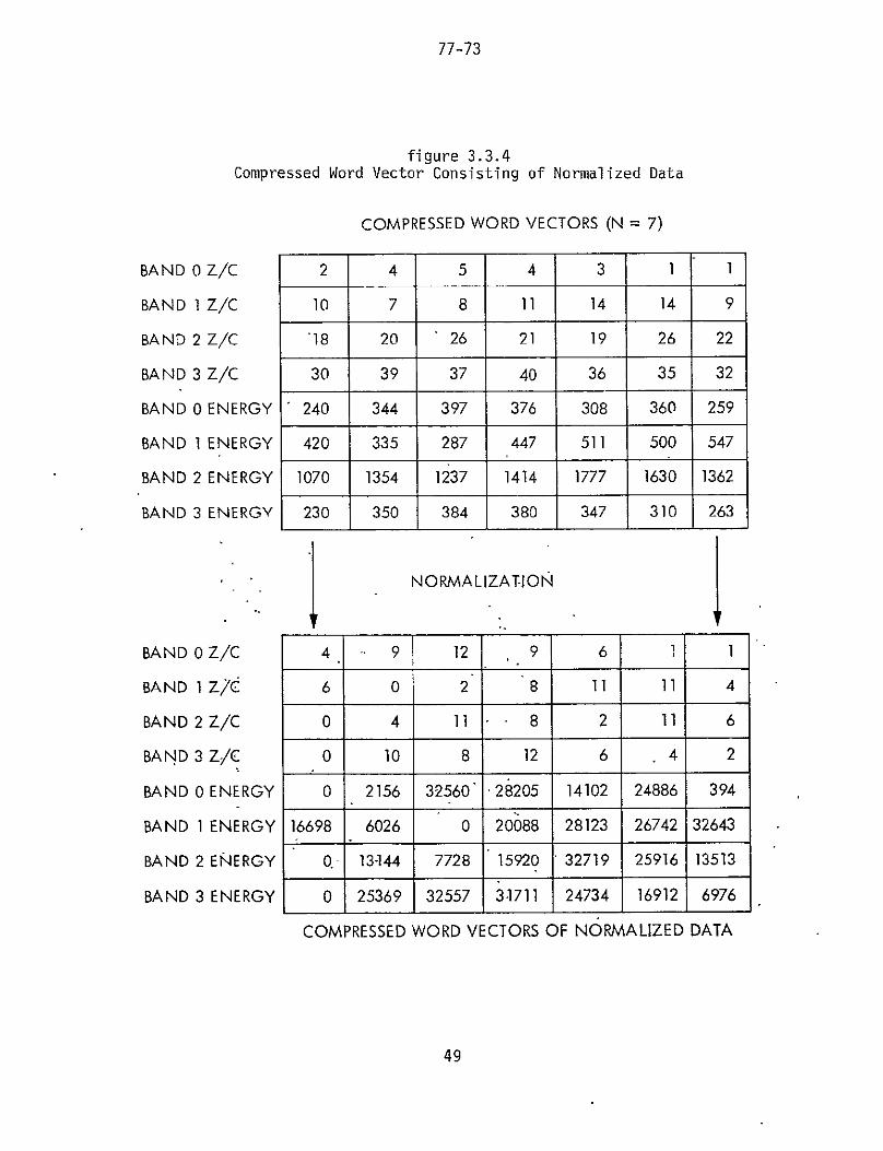
The final normalized form for a given utterance is
illustrated in figure 334 Data has been reduced from
that shown by figures 331 and 333 The feature
extraction and data compressionnormalization processes have
been designed to supply a concise robust utterance
representation to the decision process This enables the
comparisonclassification routines to evaluate the identity
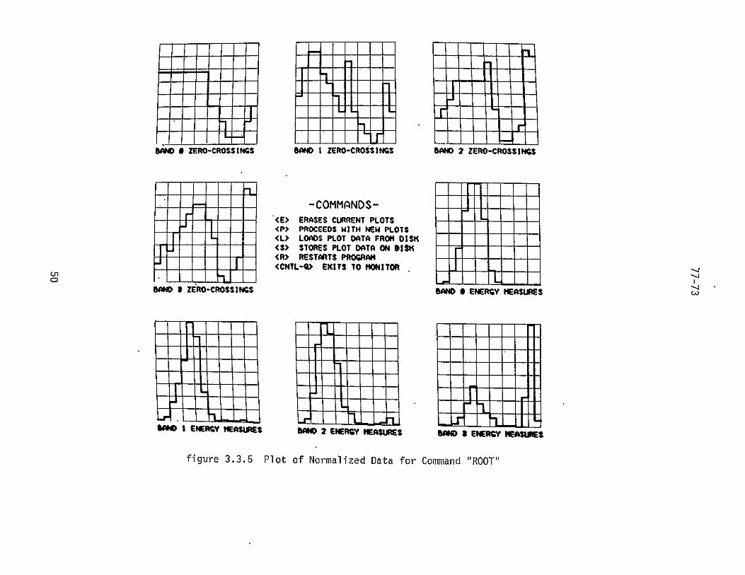
of a speech input rapidly and accurately Plots of the
input utterances ROOT and TERRAIN are displayed in
figures 335 and 336 respectively the plots were made
using utterance data in the final normalized form
34 Utterance Comparison and Classification
The feature extraction and the data
compressionnormalization routines pass along to this final
recognition system process a compact description of the
input utterance in the form of one RZ vector and one EV
48
77-73
figure 334Compressed Word Vector Consisting of Normalized Data
COMPRESSED WORD VECTORS (N = 7)
BAND 0 ZC 2 4 5 4 3 1 1
BAND 1 ZC 10 7 8 11 14 14 9
BAND 2 ZC 18 20 26 21 19 26 22
BAND 3 ZC 30 39 37 40 36 35 32
BAND 0 ENERGY 240 344 397 376 308 360 259
BAND IENERGY 420 335 287 447 511 500 547
BAND 2 ENERGY 1070 1354 1237 1414 1777 1630 1362
BAND 3 ENERGY 230 350 384 380 347 310 263
Ibull NORMALIZATION
BAND 0 ZC 4 9 12 9 6 1 1
BAND 1 ZC 6 0 2 8 11 11 4
BAND 2 ZC 0 4 11 8 2 11 6
BAND 3 ZC 0 10 8 12 6 4 2
BAND 0 ENERGY 0 2156 32560 28205 14102 24886 394
BAND 1ENERGY 16698 6026 0 20088 28123 26742 32643
BAND 2 ENERGY Q- 13-144 7728 15920 32719 25916 13513
BAND 3 ENERGY 0 25369 32557 31711 24734 16912 6976
COMPRESSED WORD VECTORS OF NORMALIZED DATA
49
80ND 9 ZERO-CROSSINGS 800 I ZERO-CROSSINGS WOAte 2 ZERO-CROSSINGS
-COMMANDSshy- (Egt ERASES CURRENT PLOTS
ltPgt PROCEEDS WITH NEW PLOTS ltLgt LOADS PLOT DATA FROM DISK ltSgt STORES PLOT DATA ON DISK lttr RESTARTS PROGRAMCRgt ltCflTL-Qgt EXITS TO MONITOR
o -- - I--ID I ZERO-CROSSINGS BAND 0 ENERGY MEASIRES
L-1I I I I H
nL-J IlI
1D I ENERGY IOSJRS WO02 ENERGY ASjS SAM IENER IEAUMS
figure 335 Plot of Normalized Data for Command ROOT
BAM 0 ZERO-CROSSINGS 84N0 I ZERO-CROSSINGS BAND 2 ZERO-CROSSINGS
i- -COMMANDS-shy- - ltEgt ERASES CURRENT PLOTS - shy
ltPgt PROCEEDS WITH NEW PLOTSltLgt LOADS PLOT DATA FROM DISK ltSgt STORES PLOT DATA ON SI19K
- - ltRgt RESTARTS PROGRAM
- L ltCNTL-gt EXITS TO MONITOR
- ]
L
BAND S ZERO-CROSSINGS LO SAM0 0 ENERGY MEASURES
too I ENERGY MEASURES DA02 ENERGY MEASUES BA05 ENERGY IE
figure 336 Plot of Normalized Data for Command TERRAIN
77-73
vector for each of the four frequency bands The input
utterance is represented by a parameterization requiring 128
-words- -of storage -(For each word prototype in the
vocabulary file only 64 words of storage are used as the
result of a further reduction step) On the basis of the
similarities of the unknown input to the known vocabulary
the comparisonclassification process selects the most
likely word identity Different similarity measures and
classification strategies provide different tradeoffs
between accuracy and speed Heuristics are often included
in systems to aid in their recognition performance
The unknown input word must in some way be compared
with each reference pattern to determine to which of the
reference patterns it is most similar In other recognition
systems this similarity has been based on the minimum
distance or the maximum correlation between a reference
pattern and the unknown utterance where a pattern sample is
treated as an N-element vector Two commonly used distance
measures are the Euclidean [ATAL 72 PAUL 70] and the
Chebyshev [BOBR 68 MCDO 00 NERO 72] norms To illustrate
the difference between these measures two N-element vectors
A and B are used
52
77-73
Euclidean distance
ED(AB) (A(j)-B(j))
=1
Chebyshev distanceN
CD(AB) =Z A(j)-B(j) I
j=1
The Euclidean measure is computationally more complex than
the Chebyshev as squaring operations are required (the
square root is not necessary as -in a minimum distance
classification the performance of a Euclidean squared
measure is identical to that of a Euclidean measure)
Often poor recognition performance results from
improper detection of the beginning or end of-an utterance
[REDD 67] This problem has been treated at the
comparisonclassification stage by two methods dynamic
programming [HATO 74 ITAK 75 LOWE 76 NIPP 76 WOLF 76]
and vector element shifting Dynamic programming is a
non-linear time normalization technique It is often used
in recognition systems which utilize linear predictive
coding feature extraction Its usefulness lies in its
ability to align critical points (eg peaks
inter-syllable minimums) when comparing two
parameterizations This pattern sample warping achieves
53
77-73
better interior matching (especially of multi-syllabic
words) than a linear time-n6-malization procedure Dynamic
programming can be -used -in -conj-unction with both the
Euclidean and Chebyshev distance measures
In section 33 reasons were presented for the choice
of a linear time normalization method for the JPL
recognizer Linear time scaling shrinks utterances to the
standard sixteen segment length This technique will cause
the utterance representation to be sensitive to the
speakers intraword pacing characteristics Interior
mismatch between an unknown utterance and a pattern sample
will affect the accuracy of the comparison operation This
performance degradation will be least for mono-syllabic
inputs as there exist fewer points at which their voicing
rates can change White [WHIT 76a] has found that linear
time normalization with left and right shifting is as good
as dynamic programming in the recognition of mono-syliabic
utterances
This shifting method of comparison is used in the
classification process The distance between two utterances
A and B using a Chebyshev norm is represented by the value
SCD
54
77-73
SCD(AB) = min(CDL(AB)((N-l)N)CD(AB) CDR(AB))
N-1
where CDL(AB) j+1)
j=1
N-1
CDR(AB) =LD(jj+I)
j=1
D(ij) = I A(i)-B(j) I
CDL(AB) and CDR(AB) are the Chebyshev distances between
vectors A and B with vector A shifted one element to the
left and to the right respectively The value ((N-l)N) is
used to adjust for the summation of N-i terms in the shifted
comparison measures and N terms in the non-shifted CD(AB)
calculation
In computing the total distance between two word
pattern samples in the JPL system eight SCD
computations are performed and accumulated (distances for
the zero-crossings in band 0 for the energies in band 3
etc) The total shifted Chebyshev distance between pattern
sample PSl and pattern sample PS2 is called TSCD and is
defined as
55
77-73
TSCD(PSIPS2) = SCD(PSl RZ band 0PS2 RZ band 0)+ SCD(PSl RZ band lPS2 RZ band 1)+ SCD(PSl RZ band 2PS2 RZ band 2)+ SCD(PSl RZ band 3PS2 RZ band 3)+ SCD(PSl EV band 0PS2 EM band 0-)+ SCD(PSl EV band lPS2 EV band 1)+ SCD(PSl EV band 2PS2 EV band 2)+ SCD(PSI EV band 3PS2 EV band 3)
In word parameterizations the value range and
information content of all elements are usually not
equivalent For example the zero-crossing ranks are values
from 0 to 2(N-I) but the energy values are represented by
15-bit numbers Information supplied by the zero-crossing
rank for band 0 might not prove as helpful in making a
recognition decision as the energy value of band 0 or band
3 For these reasons a weighted distance measure is
utilized in the comparisonclassification process of the
JPL system The total weighted shifted Chebyshev
distance between pattern sample PSI and pattern sample PS2
is called TWSCD and is calculated as
TWSCD(PSIPS2) = wz(0)SCDCPSI RZ band 0PS2 RZ band 0)+ wz(l)SCD(PSI RZ band lPS2 RZ band 1)+ wz(2)SCD(PSI RZ band 2PS2 RZ band 2)+ wz(3)SCD(PSI RZ band 3PS2 RZ band 3)+ we(0)SCD(PSl EV band 0PS2 EV band 0)+ we(l)SCD(PSI EV band IPS2 EV band 1)+ we(2)SCD(PSl EV band 2PS2 EV band 2)+ we(3)SCD(PSl EV band 3PS2 EV band 3)
where wz(i) = the ith zero-crossing band weighting andwe(i) = the ith energy band weighting
for i=0 1 2 3
56
77-73
This comparison function is implemented in the PDP-ll
assembly language and allows the development and evaluation
of different decision criteria Initially the same
weighting vectors are used for each speaker However
different vectors can be utilized for different users as the
weights ate stored along with the speakers voice
characteristic variables and vocabulary (See appendix D
for sample weights)
Using the TWSCD formula similarity measures of the
unknown utterance to each of the stored vocabulary
prototypes is computed The values returned by this
procedure represent distances between points in a vector
space of 8N where N is the number of elements in each of
the four RZ zero-crossing and four EV energy vectors A
perfect match of the unknown to one of the vocabulary words
will yield a TWSCD value of zero Progressively larger
values indicate less similar parameterizations
A common classification technique is to compare the
input utterance to each stored prototype and select as the
identity the one with the lowest distance(difference)
measure This exhaustive comparison is acceptable in
recognizers having small vocabularies but time-consuming in
larger systems As the vocabulary grows the potential
confusability between words increases (ie the vector
space has finite domain and each word is represented by a
57
77-73
point in the space) Some procedure is required to achieve
high recognition accuracy and speed in systems employing
medium or large size vocabularies (greater than 60 -wor-s)
Neely and White [NEEL 74] suggest using the ratio of
the second lowest score to the lowest as a measure of the
confidence of the nearest-neighbor decision Itakura [ITAK
75] rejects a reference pattern during matching if its
distance from the input pattern sample is ever over a
certain threshold Warren [WARR 71] dynamically removes
candidates from consideration as his system learns more
about the input Grammars have been utilized by Haton [HATO
74] and Neely and White [NEEL 74] in using syntactic
analysis to help in the performance of their systems
The JPL system uses in its classification process a
threshold upon the minimum distance found a threshold upon
a confidence measure similar to that by Neely and White and
a structured vocabulary to achieve its desired performance
The vocabulary of the current speaker consists of global and
local commands (figure 341 for partial vocabulary
appendix C for complete vocabulary) The global commands
are system commands affecting the domain and configuration
of the recognizer while the local commands are the actual
instructions being dictated to the robotic systems
58
77-73
GLOBAL COMMANDSLOCAL COMMANDS GLOBALROOT
ARM SPEAKERONDISPLAY OFFUPDATE
SIMULATE QUITFREEZEJOINTSSTATUSEYEROVERTERRAINPATH
figure 341Partial Local and Global Command Vocabulary
The local and global commands are tree-structured
(figure 342 for structure of partial vocabulary appendix
C for structure of complete vocabulary) This imposes
syntactic constraints upon the input utterances The user
begins the session at the root of the tree from which only a
subset of the vocabulary is available The state of the
recognizer is represented by the node at which the user
currently resides From a given local node the available
commands consist of the root node the current local node
itself an immediate descendent node a brother(sister)
node an immediate ancestor node or the global subtree root
node From the global subtree root node the available
commands consist of the descendent global nodes The
parameterization of the input utterance is only compared
with the prototypes of the available commands for the given
curent state This limited domain technique results in the
59
ROOT
ON OFF QUITSTATUS TERRAIN PATH STATUS SPEAKERDISPLAY JOINTS STATUS DISPLAY
UPDATE SIMULATE FREEZE UPDATE SIMULATE FREEZE
23 NODES figure 342 Partial Tree-structured Command Vocabulary
17 COMMANDS
77-73
exclusion of comparison operations involving words in the
vocabulary which are not within the current context of the
system This speeds up the recognizer
comparisonclassification process and improves system
accuracy
To insure that an undefined or inaccessible utterance
was not input two thresholding techniques are applied after
the two nearest prototypes of the current vocabulary
subset to the unknown word have been determined The
confidence of the best match is represented by the quotient
which -results from dividing the second smallest prototype
distance by the smallest prototype distance This value
must exceed a given threshold to help insure that the
pattern sample selected is a good choice relative to the
other possibilities The raw distance value of the input
utterance to the best legal match must be less than another
threshold value This test keeps the system from selecting
a legal prototype which is most similar relative to the
other legal choices yet poor in terms of absolutely
matching the input If no reference pattern meets both
these criteria the system returns a no-match response
No-match decisions do not effect the recognizer state
(Sample thresholds are provided in appendix D)
61
77-73
Wnen a valid(accessible) node meets the two previous
threshold tests the recognizer returns the digital code
representing the command identity of the node and- -update-s
its state if necessary (In reality the recognizer state
is updated to the new node position only in cases where the
new node has descendents this reduces the number of
commands needed to traverse subtrees and makes the input
facility more convenient to use Note that it is the
digital code representing the command word which is
returned not a code describing the new node as the same
word can be represented by multiple nodes in different
subtrees)
When the new node is the global subtree root node the
previous state of the recognizer is saved before being
updated and additional constraints are imposed by the
system A command following the global subtree command must
be a global operation request represented by a descendent
node of the global subtree root After its voicing the
corresponding digital code is returned and the recognizer
state is restored to the state that was occupied before the
global subtree request was made Since global commands can
change the mode of the recognizer (eg select new speaker
turn audio input off) the recognizer program must have
knowledge of the identities of these commands the digital
codes for global commands are provided in the speakers
62
77-73
vocabulary file (appendix D)
The following sample session demonstrates the command
choice constraints imposed upon the user by the syntax rules
of the vocabulary illustrated in figure 342 The user
begins the session in the ROOT state The following
commands are legal ROOT ARM EYE ROVER and GLOBAL The
command is ARM the new state is ARM The available
commands are ROOT ARM DISPLAY JOINTS STATUS EYE
ROVER and GLOBAL The command is STATUS the state remains
ARM the available commands are unchanged The next
command given is PATH PATH is an illegal command from this
point a no-match code is returned the state remains
ARM The next command is ROVER the new state is ROVER
The available commands are ROOT ARM EYE ROVER TERRAIN
PATH STATUS and GLOBAL The command is GLOBAL the old
state (ROVER)is saved the new state is GLOBAL The valid
commands are GLOBAL SPEAKER ON OFF and QUIT The
command is SPEAKER a new user vocabulary file is loaded
the new state is ROVER (the restored local state) The
available commands are again ROOT ARM EYE ROVER
TERRAIN PATH STATUS and GLOBAL This continues until the
global command QUIT is given
Figure 343 represents in flowchart form the
comparisonclassification operations in the JPL speech
recognizer The near real-time recognizition was attained
63
77-73
DETECT INPUT figure 343 UTTERANCE Comparisonclassification Procedure AND NORMALIZE
COMPARE NORMALIZED INPUT TO PROTOs OF LEGAL COMMANDS -FIND CLOSEST 2 MATCHES
CONFIDENCE VAL-c-(DIS FROM 2nd BEST MATCH TO UNKNOWN) - (DIS FROM BEST MATCH TO UNKNOWN)
CONFIDENCE VAL gt CONFIDENCE THRESHOLD RETURN
amp TRUE DIGITAL CODE BEST MATCH DISlt OF BEST MATCH MIN MATCH PROTO
DIST THRESHOLD FALSE
UPDATE STATERETURN BASED UPONNO-MATCH OLD STATE ANDCODE COMMAND
STOP
64
-7-73
by selecting and designing compression and matching
algorithms which were compatible and microprocessor
implementable These procedures included linear time
normalizing Chebyshev norm distancing utterance shifting
and distance measure weighting which operated upon reference
pattern sampmples from a vocabulary syntactically constrained
35 Organization and Operation
Three software packages were developed to generate and
supervise the speech input facility these packages are
VOCGEN LEARN and RECOGNIZE VOCGEN is comprised of the
software routines which are responsible for transforming the
users vocabulary description syntactic constraint rules
and speaking parameters into the data forms required by the
vocabulary training and word recognition systems The user
specifies the vocabulary in a hierarchical manner by means
of listing node level valuesalong with each command word
identity and digital code (In appendix C a sample
robotics application- vocabulary specification is listed
along with its corresponding VOCGEN execution summary) The
digital-code that is listedfor each command word represents
the identity of the command throughout the robot system
The syntactic constraint rules (presented in section 34)
were developed for the JPL robotics command application
however different syntax rules could be used without
65
77-73
requiring any change in the underlying data structures of
the speech input facility VOCGEN produces as its output a
vocabulary description module which is stored on floppy
disk
The LEARNing program is used to generate the prototype
set of a given user based upon the description module
produced by VOCGEN The user interactively voices examples
of each word in the vocabulary Prototype speech features
are measured and recorded Upon vocabulary learning
completion the users trained vocabulary file is stored on
floppy disk This vocabulary file can be later recalled by
means of the LEARN program to alter the stored word
prototypes It is this user trained vocabulary file which
is used by the RECOGNIZE program
The VOFEX hardware and RECOGNIZE software comprise the
speech input facility and are responsible for the
recognition of robot system commands Following detection
and recognition of an input utterance RECOGNIZE sends the
digital command code of the input to the communications
subsystem which then forwards it to the appropriate robot
subsystem for execution Figure 351 illustrates this
interface of the speech input process to the robot system
66
77-73
SPEECH INPUTamp PGS I ROBOT SYSTEM
GENERAL AUTOMATION SPC-1685 MIN ICOMPUTERI amp JPL RESEARCH ROBOT
digital command code
fCRT G]RAPHCDSD i-dtl DEC PDP-1103 DIPLY IPLY oma COMMUNICATIONS
Sdigital command code
KEYBOARD4 REMOTE DECSYSTEM-10 ISC-ECL)
speaker vocabulary
TRACKBALL
j DEC PDP-1103 NETWORK COORDINATORKEYSWITCHES
FILTERS
MICROPHONE I11 11FLOPPY DISK
speaker STORAGE (VOFEX) j vocabulary
digitalcommandLD7 code
DEC PDP-1103 I SPEECH INPUT 4 FACILITY
figure 351 Speech Input Facility - Robot System Interface
67
77-73
Tfe initial utilization of the recognition process was
to add voice input to the prototype ground subsystem (PGS)
of the robotics -r-esear-c-h -progr-am PGS is used at a control
node for the robot system and is responsible for the graphic
displays of subsystem states In this initial application
the digital codes representing voice commands are forwarded
to PGS by the communications subsystem and are processed by
PGS as are- its other input channels keyboard trackball
and keyswitches
To maintain flexibility of input form in using the PGS
subsystem the user can also specify commands via the PGS
keyboard (ie choose not to use voice input) In this
mode the PGS subsystem forwards the ASCII input characters
to the RECOGNIZEr process The speech input facility
processes character input in a similar manner to that of
audio input -When the start and end of a word is detected
(a carriage return character represents word termination)
the system checks the users vocabulary file (appendix D)
for the given input command and obtains the digital code
for the command The syntactic constraints are enforced by
insuring that the digital code of the input matches one
assigned to an available node given the current state of the
recognizer If successful in these operations the digital
command code is returned and the state is updated
otherwise -a no-match response is generated as occurs for
68
77-73
the audio input mode
The speech input and output processes execute in the
same LSI-l1 microcomputer The word recognition process has
priority over the processor as a result of its real-time
characteristics For this reason the speech input process
at specific points during its recognition operation lends
the LSI-ll processor for a limited time to the speech output
process The speech input system is interrupt driven and no
loss of data results The word recognizer continues to
listen and to collect information from the VOFEX
describing the next utterance while data compression
normalization comparison and classification is executing
and also while the processor is temporarily assigned to the
voice output process
69
77-73
CHAPTER 4 - THE AUTOMATIC VOICE OUTPUT SYSTEM
Voice response is a tool to be considered and utilized
where applicable for computer output in much the same manner
as one would select a hard copy or a CRT terminal People
react more immediately to the human voice than to any other
means of communication People are keyed to respond quickly
to the spoken word [DATA 74] Speech output was chosen to
help provide a flexible system of communicating global
information between the computer and user and is used in
parallel with the other output channels IMLAC graphics
CRT text and printed output from the remote Decsystem 10
41 General Description
The robot voice output system is used to automatically
inform the user of a critical system state or as the result
of a query to communicate to the user the current status of
a subsystem execution For example if the path planning
subsystem determined that there did not exist a path to the
desired site along which the vehicle could maneuver then a
short message conveying this could be voiced If the
manipulator arm was commanded to place a rock in an
experiment bin and upon attempting to lift the sample found
that it was too heavy for the arm mechanism another message
70
77-73
could be voiced As the result of a users request that the
current state of the integrated system operation be output
such phrases as vision 3-D correlation proceeding or
manipulator local sensing proceeding could be voiced
The following properties characterize the application
and requirements of the JPL voice output system
- short phrase voicings
- voicings are fixed in content
- medium sized extensible repertoire of voicings
- rapid response to voicing commands (minimum delay)
- understandability of voicings
- cooperative user environment
- must execute on a DEC PDP-1103 microcomputer
- flexible software design and interface
Two methods for producing voice output are generation
by means of stored digitized speech and speech synthesis
Speech can be reproduced by digitizing the original sound
storing its representation and later using digital-to-analog
conversion techniques to revoice it One can store
digitized speech in ROM or RAM and then clock it out at the
proper rate smoothing the output by a low pass filter
This procedure requires the use of large amounts of storage
and therefore is very costly and can only accommodate small
71
77-73
vocabularies or a few short phrases
Phrases are composed of words and -words are made up of
phonemes In general regardless of the variety of written
spellings of a word tnere exists only one phonetic spelling
(string of phonemes)
Synthetic speech is not as clear or distinct in its
nature as is actual speech Synthetic speech is usually
achieved by stringing together the sounds generated for each
phoneme comprising the word The lack in clarity results
largely from synthesizer transitions from phoneme to
phoneme and from improper phoneme segment durations The
subtle shadings of intonation inherent in human speech
cannot conveniently be reproduced by machine at this time
(ie intonation cannot fully be codified) [DATA 74] The
occassional recognition difficulty encountered due to this
clarity problem is alleviated as users become accustomed to
the synthesizer (especially in a cooperative user
environment with relatively short output utterances)
In using a voice synthesis rather than voice
reproduction by means of digitized speech less memory is
required for the storage of the representations of each
phrase Each word is stored as a series of phoneme codes
not as a time series of speech wave values A microcomputer
controlled speech output system involving a voice
72
77-73
synthesizer requires less processor time and is less
dependent upon performing real-time operations than one
which directs the actual timing of successive output speech
wave amplitudes In a voice synthesis system a number of
phonemes can be passed from the microcomputer storageto the
synthesizer buffer to be voiced depending upon the internal
pacing of the synthesizing-unit
The speech output facility uses a VOTRAX VS-64 Audio
Response System speech synthesizer [VOTR 00] It is
connected to a DEC PDP-1103 microcomputer by means of a
serial interface The same microcomputer is used for both
the speech input and the speech output facilities
The VOTRAX system utilizes a ROM storage unit which
contains 63 phoneme-sounds-comprising the Standard American
English dialect There are only 38 distinct phonemes in the
set as 25 of the sounds are actually different length
voicings of the principals Other characteristics of the
VOTRAX system include an input buffer to accommodate the
- difference between the data rate of the phonemes input and
the rate in which they are used by the synthesizer to
produce the pacing -of the sounds output and a modification
mechanism- to alter the production of phonemes based upon
their immediate phonemic context Four levels of inflection
can be applied to each phoneme
73
77-73
42 Organization and Operation
The software comprising the speech output facility- is
responsible for the production of a specific phrase upon
request from a robot subsystem (eg vision arm) These
utterances are static in content but extensible in number
Sample output utterances are listed in figure 421
laser generating environment maprover encountering steep terrainvision reports no objects detected in scenescene analysis completed select object of interestarm unable to reach objectobject tracking active for rover repositioningarm unable to grasp object object too largearm unable to move object object too heavyload new speaker vocabulary
figure 421Sample Output Utterances
In the selection of an utterance request format
several choices were possible The actual word could be
used to represent the request The phonetic description
(with inflections) expressed as an ASCII string could be
utilized The VOTRAX command code to which the ASCII
phoneme string must be translated could be used And
finally a digital code could be used to represent the word-
For example for the word communicate to be voiced the
following codes could be used
- communicate(the actual word character by character)
74
77-73
2KIUH2 2M Yl 10l IN IN IIl 1K IAI lAY lYl IT(the VOTRAX phonemes with inflections expressed asan ASCII string)
- 131 061 114 042 067 015 015 013 031 006 041 042 052 (the VOTRAX instruction codes expressed as 8-bit octal bytes)
- 117 (a digital code assigned to the word)
For each of these choices a tradeoff is made between the
speech output facility processing responsibility and that of
the requesting subsystem and communications link For
example if the VOTRAX instruction code were to be sent by
the subsystem the speech output handler would pass the
received code to the VOTRAX voice synthesizer and the
subsystem would be responsible for the storage retrieval
and transmitting of the substantial data volume representing
the voicing If a digital code were to be used the
subsystem would transmit to the speech output facility a
single value representing the word or utterance to be
voiced and the voice output processor would be required to
translate the code into the desired VOTRAX instructions by
means of a code file and translation tables
The output utterances require extended storage (eg
disk) and must be expressed in a form which will allow for
easy modification of utterance content as well as for the
alteration of phonetic description and inflection
assignment The most convenient form in which to represent
75
77-73
words is by phonetic composition Programs exist for
translatingytext to phonemes [ELOV 76] dictionaries are
available for providing the phonetic -spelingaf words For
these reasons a phonetic representation of words and
phrases stored on the microcomputer network floppy disk was
chosen
The speech output facility interface to the robot
system is illustrated in figure 422 Each output
utterance(phrase) is assigned a digital code to be used by
the robot system For a subsystem to make a output request
it transmits to the communications LSI-Il microprocessor the
utterance code with the speech synthesizing process as its
destination The communications processor retrieves from
the floppy disk the phonetic representation of the utterance
and forwards it to the speech output facility The voice
output process then buffers up the entire message and
translates it from its phonetic representation to the VOTRAX
instruction form These instructions are loaded into the
speech synthesizer with the necessary controls signals to
achieve the desired utterance This system organization
results in the rapid issuing of verbal responses by
minimizing the volume of data which must be handled through
the communications subsystem and extended storage
76
77-73
SPEECH OUTPUT ROBOT SYSTEM
GENERAL AUTOMATION SPC-1685 MINICOMPUTER amp JPL RESEARCH ROBOT
REMOTE DECSYSTEM-10IORA (USC-E CL)
VS-64 A IMLAC PDS-1D AUDIO GRAPHIC DISPLAY RESPONSE SYSTEM amp PGS
SYSTEM LOUD SPEAKER P dital prase tcde
DEC PDP-1103eI
SPEECHphonemes DEC PDP-1103COMMUNICATIONS PROCESSOR
Idigital phrase code amp phonemes
DEC PDP-f103 NETWORK COORDINATOR
I FLOPPY DISK
STORAGE
figure 422 Speech Output Facility - Robot System Interface
77
- 77-73
As noted in section 35 the speech output and voice
input processes execute in the same LSI-ll microcomputer
The voice-out-put -process-as a lower priority than the word
recognition process The VOTRAX speech synthesizer has data
buffering capabilities and is not as time dependent as the
speech input process The speech output process also does
not require asmuch processor time as does the voice input
process The software for these processes was designed
separately permitting their integration into the robot
system as individual facilities (subsystems)
78
77-73
CHAPTER 5 - CONCLUSION
Given the specific control application and the hardware
constraints speech input and output facilities were
implemented into the JPL robot system voice commands
from an extensible vocabulary provide a user convenient
input channel to question direct and simulate the
performance of the robot system and individual subsystems
The speech synthesis process represents an additional output
channel to be used in parallel with the hard copy units and
CRT displays These new facilities provide the JPL
system wfth an overall control capability which was
previously desired but not available
Problems were encountered and dealt with in both
individual speech input and output designs In developing a
-word recognition -system the requirements with regards to
vocabulary size processing environment and cost and the
operational constraints of accuracy rate and speed were
- difficult to reconcile In achieving the desired word
recognition performance fast and efficient compression
normalization comparison and classification algorithms had
to designed and then-implemented-as PDP-ll assembiy language
routines The PDP-1103 microcomputer has a limited
instruction set and slow processing speed A hardware
79
77-73
feature extractor (VOFEX) was required to process the data
volume necessary for isolated word recognition The VOFEX
was designed and- built based upon the requirements of the
speech input processor The close to real-time execution
condition necessitated the use of computationally simple
assembly routines suitable for the isolated word robotic
application Syntactic constraints were incorporated into
the vocabulary to improve recognition accuracy and speed
The most severe problem encountered in the speech input
work arose from the non-ideal nature of the filters used to
separate the fundamental frequencies of speech This
problem was dealt with (see section 32) by making
adjustments upon the bandpass filters and the VOFEX
hardware
In the operation of the speech output facility data
communication load characteristics and phrase storage
requirements could place heavy demands upon the LSI-11
microprocessor and the JPL robot system Through coding
techniques and choice of subsystem communication protocol
the voice output facility was integrated into the remainder
of the robot system and is able to execute along with the
speech input process in the same microcomputer
80
77-73
APPENDIX AVOice Feature Extractor (VOFEX)
The Voice Feature Extraction hardware is responsible
for- the gathering of zero-crossing and energy information
for each of the four frequency bandpasses Zero-crossing
counts and measures proportional to average energies are
accumulated over a period of time (window) as dictated by
the recognition software The inter-face between the VOFEX
and the recognizer consists of a DRV-11 parallel interface
unit and an ADAC Corporation Model 600-LSI-l1 Data
Acquisition and Control System both boards reside in the
PDP-1103 microcomputer
Each of the four analog CROWN bandpass filter outputs
are applied to separate sets of zero-crossing and energy
circuits The four circuit groups are identical except for
the amplification factor necessary to scale the inputs to
the -10 to +10 voltage range Comparators are used to
detect zero-crossings the digital ohtputs of the
comparators are applied to pairs of four-bit counters to
accumulate the axis-crossing counts
The zero-crossing counts for the four bands are routed
to a selection module The recognizer software selects from
which band the zero-crossing value (eight bits) will be
81
77-73
applied to the parallel interface input bus This is
accomplished by placing the appropriate two-bit code in the
interface output register Four additional output register
bits are used to individually place the counters in a
cleared or counting mode
Average energy measures are produced through analog
means The amplified inputs are squared and scaled to
obtain amplitudes in the 0 to +10 voltage range for normally
voiced speech Speaker inputs which saturate this VOFEX
amplitude range are clipped and trigger LEDs as a warning
indication The amplitudes are then summed through use of
an integrating capacitor circuit Capacitor voltages are
provided as inputs to the ADAC analog-to-digital converter
and can be sampled at any time by the recognizer Four
parallel output register bits (separate from the six
previously specified) are used to individually place the
integrating capacitors in either a cleared or summing mode
Schematics of the Voice Feature Extraction hardware
are provided on the following pages
82
7717 FOLDOUJT FRAME VOLDOUT FRAMp 2
4 4 H
LJ
-t
I- ORGiA PAELS8
or QUALITY~2~
OTLIGAL PGE l F POR UA
-oo
I--shy
77-73
S-FOLDOUT FRAME
op Pol -ULV
DRCNP AGE 16g 84
77-73
APPENDIX BRecognition System Parameters
MAXIMUM VOCABULARY SIZE 100 commands
NUMBER OF FREQUENCY BANDS 4
BAND SETTINGS band frequency range (Hz)0 250 - 4501 700 - 14002 1850 - 25003 3000 - 4000
WINDOW PERIOD 10 milliseconds
MAXIMUM LENGTH OF COMMAND 3 seconds
SILENCE DURATION REQUIRED TO TRIGGER END-UTTERANCE DETECT 150 milliseconds (15 window periods)
MINIMUM UTTERANCE DURATION TO BE CONSIDERED VALID INPUT 150 milliseconds (15 window periods)
LENGTH OF NORMALIZED ZC BAND VECTOR 16 segments LENGTH OF NORMALIZED ENERGY BAND VECTOR 16 segments
NORMALIZED ZC BAND VECTOR STORAGE 16 bytes (8-words) NORMALIZED ENERGY BAND VECTOR STORAGE 16 bytes (8 words)
PROTOTYPE STORAGE SIZE 128 bytes (64 words) per command
() - parameter can be changed by loading new vocabulary file
() - parameter can be changed by reassembling source code
85
77-73
APPENDIX CRobotic Vocabulary Description
This appendix is intended to supply additional
information regarding the data structures produced by the
vocabulary generation program and used by the learning and
recognition routines The user first defines the vocabulary
in a hierachical manner providing node levels and digital
codes for each command word or phrase (values are in octal
form) A sample robotic application vocabulary description
appears below
86
77-73
1 ROOT 302 SUMMARY 31
3 STATUS 323 DISPLAY 33
4 UPDATE 344 SIMULATE 354 FREEZE 36
2 ARM 37 OIGIALPAGE 3 STATUS 32 0 3 DISPLAY 33 OF POOR QUALftIY
4 UPDATE 34 4 SIMULATE 35 4 FREEZE 36
3 JOINTS 404 UPDATE 344 SIMULATE 354 FREEZE 36
3 TORQUE 414 UPDATE 344 SIMULATE 354 FREEZE 36
3 WEIGHT 423 SENSE -43
4 UPDATE 344 SIMULATE 354 FREEZE 36
2 EYE 443 STATUS 323 DISPLAY 33
4 UPDATE 344 SIMULATE 354 FREEZE 36
3 VISION 454 AUTOMATIC 464 SEGMENT 474 GROW 504 LOCATE 514 MAP 52
3 CAMERAS 534 FOCUS 54
5 UPDATE 345 SIMULATE 355 FREEZE 36
4 CONTRAST 555 UPDATE 345 SIMULATE 355 FREEZE 36
4 TRACK 565 UPDATE 345 SIMULATE 355 FREEZE 36
2 ROVER 57
87
77-73
3 STATUS 323 TERRAIN 603 PATH 613 GYRO 62
4 -UPDATE 344 SIMULATE 354 FREEZE 36
3 NAVIGATE 634 UPDATE 344 SIMULATE 354 FREEZE 36
2 GLOBAL 03 SPEAKER 13 OFF 23 ON 33 QUIT 4
The following illustration represents the above
vocabulary description in its tree format
ORIGINAL PAGE lb OF POOR QUAIT
88
JFMMAYA EYE ROVER GLOBAL
STATUS DISPLAY STATUS DISPLAY JOINTS TORQUEWEIGHTSENSESTATUSDISPLAY VISION CAMERAS STATUSTERRAINPATH GYRO NAVIGATESPEAKERON OF QUIT
UPDATESIMULATEFREEZEUPDATESIMULATEFREEZEC C C A UPDATESIMULATEFREEZEAUTOMATICSEGMEN GROWLOCAE MAP FOCUSCONRAST TACK UPDATEATE SIMULATE REUPEZ UP LAT FREZ YZ AUT EN GRWSIMUWPFCU OTRS TAKAP E FREEZE UPDAT IULTFREZEltAA00
6MNODESm3 cohNDS
77-73
The vocabulary generation program receives as its input
the hierarchical description of the vocabulary and produces
an untrained vocabulary description file consisting of
speaker dependent variables (see appendix D) syntactic
constraint rules command prototype storage and a digital
codecommand entry table The command prototype storage
area remains vacant until the user trains the recognizer for
the given vocabulary by means of the LEARN program The
following is the execution summary produced by the VOCGEN
program for the sample vocabulary The LLSCTAB offset
represents the relative address in the syntactic constraint
structure for the given node (not digital command) entry
The syntactic constraint structure lists for each node in
the vocabulary tree the relative address in the prototype
storage for the normalized command data the digital command
code and the LLSCTAB offsets for the command nodes which can
legally follow ACGLOBAL is the LLSCTAB offset for the
GLOBAL command subtree
90
77-73
VOCABULARY GENERATION EXECUTION SUMMARY
VOCABULARY STRUCTURE TABLE
LEVEL WORD ENTRY DIG CODE LLSCTAB OFFSET
000001 ROOT 000030 000000 000002 SUMMARY 000031 000020 000003 STATUS 000032 000044 000003 DISPLAY 000033 000052 000004 UPDATE 000034 000076 000004 SIMULATE 000035 000104 000004 FREEZE 000036 000112 000002 ARM 000037 000120shy000003 STATUS 000032 000154 000003 DISPLAY 000033 000162 000004 UPDATE 000034 000216 000004 SIMULATE 000035 000224 000004 FREEZE 000036 000232 000003 JOINTS 000040 000240 000004 UPDATE 000034 000274 000004 SIMULATE 000035 000302 000004 FREEZE 000036 000310 000003 TORQUE 000041 000316 000004 UPDATE 000034 000352 000004 SIMULATE 000035 000360 000004 FREEZE 000036 000366 000003 WEIGHT 000042 000374 000003 SENSE 000043 000402 000004 UPDATE 000034 000436 000004 SIMULATE 000035 000444 000004 FREEZE 000036 000452 000002 EYE 000044 000460 000003 STATUS 000032 000510 000003 DISPLAY 000033 060516 000004 UPDATE 000034 000546 000004 SIMULATE 000035 000554 000004 FREEZE 000036 000562 000003 VISION 000045 000570 000004 AUTOMATIC 000046 000624 000004 SEGMENT 000047 000632 000004 GROW 000050 000640 000004 LOCATE 000051 000646 000004 MAP 000052 000654 000003 CAMERAS 000053 000662 000004 FOCUS 000054 000712 000005 UPDATE 000034 000740 000005 SIMULATE 000035 000746 000005 FREEZE 000036 000754 000004 CONTRAST 000055 000762 000005 UPDATE 000034 001010
91
77-73
000005 SIMULATE 000035 001016 000005 FREEZE 000036 001024 000004 TRACK 000056 001032 000005 UPDATE 000034 001060 000005 SIMULATE 00003 001066 000005 FREEZE 000036 001074 000002 ROVER 000057 001102 000003 STATUS 000032 001134 000003 TERRAIN 000060 001142 000003 PATH 000061 001150 000003 GYRO 000062 001156 000004 UPDATE 000034 001210 000004 SIMULATE 000035 001216 000004 FREEZE 000036 001224 000003 NAVIGATE 000063 001232 000004 UPDATE 000034 001264 000004 SIMULATE 000035 001272 000004 FREEZE 000036 001300 000002 GLOBAL 000000 001306 000003 SPEAKER 000001 001326 000003 OFF 000002 001334 000003 ON 000003 001342 000003 QUIT 000004 001350 177777 177777 001356
92
77-73
DIGITAL CODE- WORD ENTRY TABLE
DIG CODE
000030 000031 000032 000033 000034 000035 000036 000037 000040 000041 000042 000043 000044 000045 000046 000047 000050 000051 000052 000053 000054 000055 000056 000057 000060 000061 000062 000063 000000 000001 000002 000003 000004
NDWDS 000041
WORD ENTRY
ROOTSUMMARYSTATUSDISPLAYUPDATESIMULATEFREEZEARMJOINTSTORQUEWEIGHTSENSEEYEVISIONAUTOMATICSEGMENTGROWLOCATEMAPCAMERASFOCUSCONTRASTTRACKROVERTERRAINPATHGYRONAVIGATEGLOBALSPEAKEROFFONQUIT
93
77-73
SYNTACTIC CONSTRAINT STRUCTURE
[LLSCTAB OFFSET] [PROTOTYPE OFFSET] [DIG CODE]gt[LLSCTAB OFFSET OF LEGAL COMMAND1]gt[LLSCTAB OFFSET OF LEGAL COMMAND2]gt[LLSCTAB OFFSET OF LEGAL COMMAND3]gt ETC
000000 000000 000030gt000000gt000020gt000120gt000460gt001102
000020 000200 000031gt000020gt000044gt000052gt000120gt000460gt001102gt000000
000044 000400 000032
000052 000600 000033gt000052gt000076gt000104gt000112gt000044gt000020gt000000
000076 001000 000034
000104 001200 000035
000112 001400 000036
000120 001600 000037gt000120gt000154gt000162gt000240gt000316gt000374gt000402gt000460gt001102gt000020
94
77-73
gt000000
000154 000400 000032
000162 000600 000033 gt000162 gt000216 gt000224 gt000232 gt000240 gt000316MAG gt000374
gt000402 gt000154 gt000120 gt000000
000216 001000 000034
000224 001200 000035
000232 001400 000036
000240 002000 000040 gt000240 gt000274 gt000302 gt000310 gt000316 gt000374 gt000402 gt000162 gt000154 gt000120 gt000000
000274 001000 000034
000302 001200 000035
0003i0 001400 000036
000316 002200 000041 gt000316 gt000352 gt000360 gt000366 gt000374 gt000402 gt000240 gt000162 gt000154
95
77-73
gt000120 gt000000
000352 001000 000034
000360 001200 000035
000366 001400 000036
000374 002400 000042
000402 002600 000043 gt000402 gt000436 gt000444 gt000452 gt000374 gt000316 gt000240 gt000162 gt000154 gt000120 gt000000
000436 001000 000034
000444 001200 000035
000452 001400 000036
000460 003000 000044 gt000460 000510
gt000516 gt000570 gt000662 gt001102 gt000120 gt000020 gt000000
000510 000400 000032
000516 000600 000033 gt000516 gt000546 gt00 0554 1pA-GE IS gt00 0562 gt000570
OR-IV QJJWIVOFYoR Q gt000662 gt000510 gt000460
96
77-73
gt000000 000546 001000 000034 G17T0V4J pAG
000554 001200 000035
000562 001400 000036
000570 003200 000045 gt000570 gt000624 gt000632 gt000640 gt000646 gt000654 gt000662 gt000516 gt000510 gt000460 gt000000
000624 003400 000046
000632 003600 000047
000640 004000 000050
000646 004200 000051
000654 004400 000052
000662 004600 000053 gt000662 gt000712 gt000762 gt001032 gt000570 gt000516 gt000510 gt000460 gt000000
000712 005000 000054 gt000712 gt000740 gt000746 gt000754 gt000762 gt001032 gt000662 gt000000
97
77-73
000740 001000 000034
000746 001200 000035
000754 -001400 -000036shy
000762 005200 000055 gt000762 gt001010 gt001016 gt001024 gt001032 gt000712 gt000662 gt000000
001010 001000 000034
001016 001200 000035
001024 001400 000036
001032 005400 000056 gt001032 gt001060 gt001066 gt001074 gt000762 gt000712 gt000662 gt000000
001060 001000 000034
001066 001200 000035
001074 001400 000036
001102 005600 000057 gt001102 gt001134 gt001142 gt001150 gt001156 gt001232 gt000460 gt000120 gt000020 gt000000
001134 000400 000032
98
77-73
001142 006000 000060
001150 006200 000061
001156 006400 000062 gt001156 gt001210 -gt001216 gt001224 gt001-232 gt001150 ORGh 4AJ PAGE 5 gt001142 gt001134 O POOR QUALITY gt001102 gt000000
001210 001000 000034
001216 001200 000035
001224 001400 000036
001232 006600 000063 gt001232 gt001264 gt001272 gt001300 gt001156 gt001150 gt001142 gt001134 gt001102 gt000000 001264 001000 000034
001272 001200 000035
001300 001400 000036
001306 007000 000000 gt001306 gt001326 gt001334 gt001342 gt001350
001326 007200 000001
001334 007400 000002
001342 007600 000003
99
77-73
001350 010000 000004
ACGLOBAL 001306
VOCABULARY GENERATION SUCCESSFULshy
100
-7773
APPENDIX DUser Vocabulary File
A users vocabulary file is composed of four sections
the speaker dependent variables the syntactic constraint
rules the command prototypes and the digital codecommand
entry table The speaker dependent variable section
contains the parameters used in the start and end detect of
an utterance the- vector difference weights used by the
classification routines the thresholds used by the decision
procedure and the digital codes of special global commands
needed by the recognition supervisor
The syntactic constraint area holds the tree-structured
vocabulary information and is organized in a preorder
fashion For each command node in the tree its prototype
offset address and digital code of the entry is stored
along with a lists of valid(accessible) nodes available from
the given state
The prototype storage section holds the normalized
zero-crossing and energy information for each distinct
command (digital code) in the vocabulary Given the current
normalization techniques used a vocabulary of 100 commands
would require 125K bytes for prototype storage (56K bytes
of storage are available in the DEC PDP-1103
101
77-73
microcomputer)
The digital codecommand entry table stores the actual
command identity (in ASCII character format) for each
digital code This table is used by the recognizer program
to process keyboard input and by the learning program to
prompt the user during vocabulary training
A sample user vocabulary file follows (values are in
octal form) Sample syntactic constraint data structure and
digital codecommand entry table can be found in appendix C
102
77-73 ORIGN p 01pooR QPAGJamp J6
SPEAKER DEPENDENT VARIABLESESTART MINIMUM ENERGIES NEEDED T0 TRIGGER START 30- BAND 0 34 BAND 1 24 BAND 2 24 BAND 3
EEND MAXIMUM ENERGIES NEEDED TO TRIGGER END24 BAND 030 BAND 120 BAND 220 BAND 3
ENDWCNT 17 NUMBER OF CONSECUTIVE SILENCE WINDOWSREQUIRED TO TRIGGER END DETECT
TOOSHORT 17 UTTERANCE HAS TO BE LONGER THAN THIS LENGTH
ERANGE MINIMUM ENERGY VALUE RANGES FOR AFTERNORMALIZATION ELSE IGNORE INPUT
50 BAND 050 BAND 140 BAND 230 BAND 3
DECWEIGHTS FEATURE DECISION WEIGHTS1 BAND 0 - ZC6 BAND 1 - ZC6 BAND 2 - ZC4 BAND 3 - ZC1 BAND 0 - ENERGY2 BAND 1 - ENERGY2 BAND 2 - ENERGY1 BNAD 3 - ENERGY
MAXDIF 6000 MAXIMUM DISTANCE BETWEEN UNKNOWN INPUT ANDBEST PROTOTYPE FOR ACCEPTANCE (THRESHOLD)
MINQUO 114 CONFIDENCE RATIO x 64 MUST BE GREATER THANTHIS VALUE (THRESHOLD)
MAXGCODE 20 MAXIMUM GLOBAL COMMAND CODEILLEGAL -1 DIGITAL CODE OF A NO-MATCH ENTRYDCGLOBAL 0 DIGITAL CODE OF GLOBALDCSPEAKER 1 DIGITAL CODE OF SPEAKERDCON 2 DIGITAL CODE OF ONDCOFF 3 DIGITAL CODE OF OFFDCEXIT 4 DIGITAL CODE OF EXIT
103
77-73
SYNTACTIC CONSTRAINT STORAGEACGLOBAL 1306 ABSOLUTE OFFSET IN LLSCTAB FOR GLOBALENTRYLLSCTAB STORAGE FOR 100 UNIQUE COMMANDS
PROTOTYPE PATTERN STORAGEPROTOS STORAGE FOR 100 NORMALIZED COMMANDS
DIGITAL CODECOMMAND ENTRY TABLENENTRY 0 NUMBER OF UNIQUE COMMANDS IN VOCABULARYENTRYS A DIGITAL CODECOMMAND SPELLING ENTRY FOR
EACH COMMAND IN THE VOCABULARY
104
77-73
BIBLIOGRAPHY
ADAC 00 Instruction Manual for the ADAC CorporationModel 600-LSI-11 Data Acquisition and ControlSystem ADAC Corp Woburn Massachusetts nodate
ATAL 72 Atal BS Automatic Speaker RecognitionBased on Pitch Contours Journal of theAcoustical Society of America vol 52 No6 pp1687-1697 December 1972
ATAL 76 Atal BS and Rabiner LR A PatternRecognition Approach to Voiced-Unvoiced-SilenceClassification with Applications to SpeechRecognition IEEE Transactions on AcousticsSpeech and Signal Processing Vol- ASSP-24No 3 pp201-212 June 1976
ATMA 76 Atman W The Time Has Come to Talk ByteNo 12 ppZ6-33 August 1976
BEEK 00 Beek B et al Automatic SpeakerRecognition Systems AGARD ConferenceProceedings No 94 on ArtificialIntelligence no date
BEEK 71 Beek B and Creech J Techniques for Automatic - Speaker Identification Joint Automatic Control Conference Proceedings p442 1971
SBEET 00 -Beetle DH Access to Remote Data Systemsvia Conversational Speech IBM Corpreport no date
BOBR 68 Bobrow D and Klatt D A Limited SpeechReoqnition System FJCC pp305-318 1968
CROW 00 Crown Instruction Manual VFX2 Dual-ChannelFilterCrossover Crown International IncElkhart Indiana no date
DATA 74 All About Voice Response Datapro ResearchCorp report September 1974
105
77-73
DEC 76 Digital Microcomputer Handbook DigitalEquipment Corp Maynard Mass-acusetts 1976
DIXO 75 Dixon NR and Silveman H-F A-Description of a Parametrically ControlledModular Structure for Speech Processing IEEETransactions on Acoustics Speech and Sign-aTProcessing Vol ASSP-23 NoY pp87-91February 1975
ELOV 76 Elovitz HS et al Automatic Translationof English Text to Phonetics by Means ofLetter-to-Sound Rules Naval ResearchLaboratory report No 79A8 January 1976
FLAN 65 Flanagan JL Speech Analysis Synthesis andPerception Academic Press Inc New York 1965
GLEN 71 Glenn JW and Hitchcock MH With aSpeech Pattern Classifier Computer Listens toits Masters Voice Electronics May 1971
GLEN 75 Glenn JW Machines You Can Talk ToMachine Design vol 47 No 11 pp 72-75May 1975
GOLD 66 Gold B Word Recognition Computer ProgramMassachusetts Institute of Technology TechnicalReport No 452 1966
GRAD 75 Grady M and Hercher M Advanced SpeechTechnology Applied to Problems of Air TrafficControl National Aerospace ElectronicsConference Proceedings pp 541-546JruTne175
HATO 74 Haton J P A Practical Application of a Real-Time Isolated Word Recognition System Using Syntactic Constraints IEEE Transactions on Acoustics S and s hi Processing Vo-l ASSP-22 No b pp- 416-419 December1974
HERS 73 Herscher MB and Cox RB Talk to theComputer Naval Matetial Industrial ResourcesOffice- Manufacturing Technology BulletinAugust 1973
HONG 76 Hong JP Real Time Analysis of voicedSounds United States Patent No 3978287August 1976
106
77-73
ITAH 73 Itahashi S et al Discrete-WordRecognition Utilizing a Word Dictionary andPhonological Rules IEEE Transactions on Audioand Electroacoustics Vol AU-21 No 3 pp=9-249 June 1973
ITAK 75 Itakura F Minimum Prediction ResidualPrinciple Applied to Speech Recognition IEEE Transactions on Acoustics Speec and 4jna Processing vol ASSP-23 No i pp February 1975
LEWI 77 Lewis RA and Johnston AR A ScanningLaser Rangefinder for a Robotic Vehicle JetPropulsion Laboratory Technical Memorandum No33-809 February 1977
LITT 65 Littler TS The Physics of the EarMacmillan Company New York 1965--
LOWE 76 Lowerre BT The HARPY Speech RecognitionSystem Carnegie-Mellon University phddissertation April 1976
MAKH 71 Makhoul J Speaker Adaptation in a LimitedSpeech Recognition System IEEE Transactionson Computers Vol C-20 No 9 pp1057-1063 September 1971
MAKH 73- Makhoul J Spectral Analysis of Speech byLinear Prediction IEEE Transactions on Audioand Electroacoustics ol AU-21 No 3 pp -f-148 June 1973
MART 76 Martin TB Practical Applications of voiceInput to Machines Proceedings of the IEEEVol 6-4 No 4 April 1976
MCDO 00 Design and Performance of a Large VocabularyDiscrete Word Recognition SystemMcDonnell-Douglas Technical Report NoNASA-CR-120165MDC-G4829 no date
NEEL 74 Neely R and White G On the Use of Syntaxin a Low-Cost Real Time Speech RecognitionSystem IFIP Proceedings pp 748-752 August1974
NERO 72 Neroth C Audio Graphic Programming SystemUniversity of California_ Berkeley phddissertaton December 197-2
107
77-73
NIED 75 Niederjohn RJ A Mathematical Formulationand Comparison of Zero-Crossing AnalysisTechniques Which Have Been Applied to AutomaticSpeech Recognition IEEE Transactions onAcoustics Speech and Si nal Processing VoTASSP-23 No 4 pp 373-30 August 1975
NIPP 76 DP voice Recognition System Nippon ElectricCo Ltd announcement 1976
PAUL 70 Paul JE A Limited VocabularyMulti-Speaker Automatic Isolated WordRecognition System North Carolina StateUniversity phd dissertation 1970
PETE 51 Peterson E Frequency Detection and SpeechFormants Journal of the Acoustical Society ofAmerica Vo l -o6-November 1951
RABI 75 Rabiner LR and Sambur MR An Algorithmfor Determining the Endpoints of IsolatedUtterances Bell System Technical JournalVol 54 No 2 pp 297-315 February 1975
RABI 76 Rabiner LR and Sambur MR SomePreliminary Experiments in the Recognition ofConnected Digits IEEE Transactions onAcoustics Speech and Processin VolASSP-24 No 2 pp 170-182 April71976
REDD 67 Reddy DR Computer Recognition of Connected Speech Journal of the Acoustical Society of America V617= ppT329-347 July-DecmbF 1967
REDD 76 Reddy DR Speech Recognition by Machine AReview Proceedings of the IEEE Vol 64 No4 April M9
RICE 76 Rice DL Friends Humans andCountryrobots Lend Me your Ears Byte No12 pp 16-24 August 1976
SAMB 75 Sambur MR and Rabiner LR ASpeaker-Independent Digit- Recognition SystemBell System Technical Journal Vol 54 NoTT-anuary 1975
SHAN 49 Shannon CE Communication in the Presenceof Noise Proceedins of the IRE vol 37No 1 pp g2January i1Tg
108
77-73
SHUR 76 Shure Models SE30 and SE30-2E GatedCompressorMixer Operating and Service ManualShure Brothers Inc Evanston Illinois 1976
SILV 74 Silverman H and Dixon NR AParametrically Controlled Spectral AnalysisSystem for Speech IEEE Transactions onAcoustics peech and signal Processing voTASSP-22 No 5 pp762f-381 Octobe 74
SNEL 75 Snell JD Speech Recognition by aMicroprocessor A Mobile Man-Machine Interfacefor the JASON Robot Project University ofCalifornia Berkeley unpublished proposalMarch 1975
VICE 69 Vicens P Aspects of Speech Recognition byComputer Stanford University phddissertation April 1969
VOTR 00 VOTRAX Audio Resonse Syste Operators ManualVocal Interface Division Federal Screw WorksTroy Michigan no date
WARR 71 Warren JH A Pattern ClassificationTechnique for Speech Recognition IEEETransactions on Audio and Electroacousti-csVol AU-19 No pp4 281-285 December1971
WASS 75 Wasson D and Donaldson R SpeechAmplitude and Zero- Crossings for AutomatedIdentification of Human Speakers IEEETransactions on Acoustics Speech and Sign-alProcessing VoT ASSP-25 No -- pp3r-392Xugust 1975
WELC 73 Welch JR and Oetting JD FormantExtraction Hardware Using Adaptive LinearPredictive Coding Philco-Ford Corp finalreport August 1973
WHIT 76a White GM and Neely RB SpeechRecognition Experments with Linear PredicationBandpass Filtering and Dynamic ProgrammingIEEE Transactions on Acoustics SpeehSnal Processng V-3T
andpp-S24No2
183-188 April 1976
WHIT 76b White GM Speech Recognition A TutorialOverview Computer May 1976
109
77-73
WOLF 76 Wolf JJ HWIM Speech Understanding SystemSeminar Jet Propulsion Laboratory PasadenaCalifornia November 1976
110 NASA-JPL-ComI L A Calif
PUBLVCATION 77-73

NOTICE
THIS DOCUMENT HAS BEEN REPRODUCED
FROM THE BEST COPY FURNISHED US BY
THE SPONSORING AGENCY ALTHOUGH IT
IS RECOGNIZED THAT CERTAIN PORTIONS
ARE ILLEGIBLE IT IS BEING RELEASED
IN THE INTEREST OF MAKING AVAILABLE
AS MUCH INFORMATION AS POSSIBLE
TECHNICAL REPORT STANDARD TITLE PAGE
1 Report No JPL Pub 77-73 2 Government Accession No 3 Recipients Catalog No
4 Title and Subtitle 5 Report DateDecember 15 1977
Robotics Conitrol Using Isolated Word Recognition 6 Performing Organization Code of Voice Input
7 Author(s) 8 Performing Organization Report No
John Martin Weiner
9 Performing Organization Name and Address 1 Work Unit No
JET PROPULSION LABORATORY11 Contract or Grant NoCalifornia Institute of Technology
4800 Oak Grove Drive NAS 7-100
Pasadena California 91103 13 Type of Report and Period Covered
12 Sponsoring Agency Name and Address JPL Publication
NATIONAL AERONAUTICS AND SPACE ADMINISTRATION 14 Sponsoring Agency Code Washington DC 20546
15 Supplementary Notes
16 Abstract
A speech inputoutput system is presented that can be used to communicate with atask oriented system Human speech commands and synthesized voice output extendconventional information exchange capabilities between man and machine by utilizing audio input and output channels
The speech input facility described is comprised of a hardware feature extractorand a microprocessor implemented isolated word or phrase recognition system Therecognizer offersa medium sized (100commands) syntactically constrained vocabushylary and exhibits close to real-time performance The major portion of the recognishytion processing required is accomplished through software minimizing the complexityof the hardware feature extractor
The speech output facility incorporates a commercially available voice synthesizerbased upon phonetic representations of words The same DEC PDP-103 microcomputerused in the voice input system controls the speech output operation
17 Key Words (Selected by Author(s)) 18 Distribution Statement Computer Operations and Hardware Computer Programming and Software Unclassified - Unlimited Cybernetics
19 Security Classif (of this report) 20 Security Classif (of this page) 21 No of Pages 22 Price
Unclassified Unclassified U
HOW TO FILL OUT THE TECHNICAL REPORT STANDARD TITLE PAGEaid 142 6itemnsLeave
Use all capital letters for title (item 4) and 13 agree with the correspondi g information on theMake items 1 4 5 9 12 as followsreport cover
Complete the remaining items by report ripients
blank Reserved for use Incoverereport3 Recipients Catalog No
ing information from Inclu e corresp
author if it differ from that of the 7 Author(s) an
list the affiliation of -addition
organizationnumber pfrming organizationperforming this rnsert if Report No
Performing Organizationassignto ple 923-50-10-06-72)8 o examide code(f
wishes U se the agency-w authorizedUnit 10 Work No hich the work was
1is blankshywhich uniquely identifies the work unit under
lea performing organizations will
the report was er whNon-NASA
Insert the number of the contract or grant u
11 prepared ot in l deIsewhere but useful
sn teEnter informationNotes in
r nlt of (or by) P 15 Supplementary
To be published Prepared in cooperation with
such as of aysu of thetuifac at conference words)d200exce thesibleIf po
Include a brief (not to the report
Ifthe report contains16 Abstract dclassifie most significant information containe
e un mentio n it h re
abstract of a classified report should ur t u elite ra
a sign ific ant bibl iography or bydthe au Jor that identif y
elctro e Insert t er ms or shor t p
I17 K ey W ords su fcin l
the principal subjects covered in tI e r pot and that are to be used for cataloging tsrused to
specific and precise of the authorized stateme
foron ationEnter dissemirf or a limitation onDistributionStatement A toied statements
denote releasability to the publi ens ino m to
8reasons other than security of de
and NAS Contractors onlyU S Government and Cor ractors only
NASA and are Unclassified-Unlimited on y U S Government Agencies
Reports carryng a securityNOTE(of repor ) urity and down-
Security Classification Requ~ ements Checklist
will require additi nal markings giving se 19
classification grading information ianual (DoD as specifiedby the Security
522 2-M)
and the DoD Industrial Security Because this page may be
it should(of this pag 0 NOT - and data banks
Security Classification bi gaphies20
used in preparing announcements indicate sepa-If a classification is required
of the title and the abstract by followihg these items be unclassified if possible
as applicable for
rately the classification or (S) for unclassified [or
(C)
with either (U)
classified items
of Pages Insert the number of pages for Federal Scientific and
21 No Insert the price set by the Clearinghouse
22 Price or the Government Printing Office if known
InformationTechnical
JPL PUBLICATION 77-73
Robotics Control UsingIsolated Word Recognition of Voice Input John Martin Weiner
December 15 1977
National Aeronautics and Space Administration
Jet Propulsion LaboratoryCalifornia Institute of TechnologyPasadena California 91103
Prepared Under Contract No NAS 7-100National Aeronautics and Space Administration
77-73amp
PREFACE
The work described in thisreport was performed in
partial fulfillment of the Master of Science in Computer
Science Degree at the University of California Los
Angeles under the cognizance of the Earth and Space
Sciences Division of the Jet Propulsion Laboratory
iii
-77-73
-ACKNOWLEDGMENTS-
I wish to express mygratitude to Dr B Bussell Dr
A Klinger and Dr P Ladefoged of my committee for their
encouragement and guidance throughout the course of this
work I also thank Dr Bussell my thesis advisor for his
willingness in my undertaking this particular project
I also extend my appreciation to my colleagues in the
Robotics Research Group at the Jet Propulsion Laboratory
where most of this work was undertaken In particular I
would like to thank Dr D Williams for the great deal of
time he spent in discussing problem areas with me and for
his valuable suggestions I thank Ray Eskenazi for his
efforts in designing and constructing the speech
preprocessing hardware
iv
77-73
TABLE OF CONTENTS
PAGE
List of Figures vi
Abstract
Use of Audio for Robotics Control 1
vii
1
2 Human Mechanisms for Speech Generationand Recognition 8
21 Human Speech Production 8
22 Human Speech Recognition 10
3 The Automatic Isolated Word Recognition System 12
31 General Description 1332 Feature Extraction 1733 Data Compression and Normalization 2734 Utterance Comparison and Classification 4835 Organization and Operation 65
4 The Automatic Voice Output System 70
41 General Description 7042 Organization and Operation 74shy
795 Conclusion
Appendix A - VOice Feature EXtractor (VOFEX) 81Appendix B - Recognition System Parameters 85Appendix C - Robotic Vocabulary Description 86Appendix D - User Vocabulary File 101
Bibliography 105
77-73
LIST OF FIGURES
PAGE
411 JPL Research Robot 12 JPL Robot System- Processor Organization 5311 Isolated Word Recognition System Components 16321 Software Supervised Feature Extraction 22322 Hardware (VOFEX) Supervised Feature Extraction 25331 Utterance Location Based Upon
35Non-silence Detection 332 Utterance Detection Procedure 37 333 Compressed Word Vector Consisting of Raw Data 44334 Compressed Word Vector Consisting of
Normalized Data 49335 Plot of Normalized Data for Command ROOT 50336 Plot of Normalized Data for Command TERRAIN 51341 Partial Local and Global Command Vocabulary 59342 Partial Tree-structured Command Vocabulary 60343 Comparisonclassification Procedure 64351 Speech Input Facility - Robot System Interface 67421 Sample Output Utterances 74422 Speech Output Facility - Robot System Interface 77
vi
77-73
ABSTRACT OF THE THESIS
A speech inputoutput system is presented that can be
used to communicate with a task oriented system Human
speech commands and synthesized voice output extend
conventional information exchange capabilities between man
and machine by utilizing audio input and output channels
The speech input facility described is comprised of a
hardware feature extractor and a microprocessor implemented
isolated word or phrase recognition system The recognizer
offers a medium sized (100 commands) syntactically
constrained vocabulary and exhibits close to real-time
performance The major portion of the recognition
processing required is accomplished through software
minimizing the complexity of the hardware feature extractor
The speech output facility incorporates a commercially
available voice synthesizer based upon phonetic
representations of words The same DEC PDP-103
microcomputer used in the voice input system controls the
speech output operation
vii
77-73
CHAPTER 1 - USE OF AUDIO FOR ROBOTICS CONTROL
Generally man-machine communication is in a form
consistent with the operational requirements of the machine
rather than in a form convenient to the user Keyboard
input and hard copy output are examples of such interactions
that can be replaced by audio communication Advantages
inherent in voice control arise from its universality and
speed Speech exhibits a high data rate for an output
channel The voice also the besthuman is form of
interactive communication when an immediate reaction is
desired Voice input and output help provide a flexible
system of communication between the computer and user
Speech permits the hands eyes and feet to remain free
allows the operator to be mobile and can be used in parallel
with other information channels
The idea of automatic recognition of speech is not new
At the time of this research limited word recognition
systems have been used in industry some implemented
systems have also incorporated voice output to provide
two-way audio man-machine communication Trans World
Airlines Inc and United Air Lines Inc use speech input
in some of their baggage sorting facilities [HERS 73]
1
77-73
Voice input systems are also used by shippers to separate
and route parcels [GLEN 71 NIPP 76] in numerically
controlled machine tool programming to specify part
descriptions [MART 76] and in compressor repair facilities
to record serial numbers of air conditioning components
returned for service Some air traffic controllers and
aircraft crew members are trained on simulators which
incorporate speech input and synthesized voice output [GLEN
75 GRAD 75] Automatic word recognizers and speech output
devices enable the telephone to be used in a conversational
manner to query access and modify remote data base systems
[BEET 00] Voice recognition techniques have been applied
in security systems to recognize or verify the identities of
persons on the basis of their speech patterns [ATAL 72 SEEK
71 BEEK 00] Other examples of speech output devices
include automatic text readers for the visually handicapped
and the audio reporting of credit or account information for
retail stores and banks [DATA 74] Simple speech
recognition systems are currently available which can handle
a vocalulary of 15-150 words and cost from $10000 to
$20000 [GLEN 75]
The work presented in this report is directed at the
design and implementation of a voice inputoutput facility
to be used to communicate with the robotic systems at the
Jet Propulsion Laboratory Pasadena California The robot
0L
77-73
system (figure 11) is a breadboard intended to provide a
tool for testing various approaches to problem-solving and
autonomous operation [LEWI 77] The major components of the
integrated system include perception(vision) path planning
locomotion manipulation simulation and control The
processors which perform these operations (figure 12)
include a remote Decsystem 10 a General Automation
SPC-1685 minicomputer an IMLAC PDS-ID graphics display
system and three DEC PDP-1103 microcomputers One
PDP-103 with a floppy disk drive serves as the
microcomputer network coordinator The second PDP-1103 is
used as a communications controller for the distributed
system and the third is used for the speech inputoutput
interface The voice input system is composed of both
hardware and software processing which make up the isolated
word recognizer Voice output is accomplished through use
of a VOTRAX VS-64 Audio Response System under control of
the third microcomputer This processor configuration was
chosen to allow flexibility in the robotics research
program
The speech inputoutput system presented can be used to
control the execution of a task oriented system The
application presented in this work is directed at providing
a user with the capability to question direct and simulate
the performance of the JPL robot system and its individual
3
77-73
figure 11 JPL Research Robot
4
figure 12JPL Robot System-
Processor Organization
STORAGEA
SPEHDEC PROCESSING
HARDWARE
77-73
IMLAC PDS-1DGRAPHIC REMOTEDISPLAY DECSYSTEM-10SYSTEM (UJSC-ECL)
DEC PDP-1103 COMMUNICATIONS PROCESSOR
DEC PDP-1 103 IGENERAL NETWORK AUTOMATION COORDINATOR SPC-1685
PDP-1 103 JPL SPEECH RESEARCHINUUPTROBOT INPUTOUTPUTFACILITY
5
77-73
subsystems The IMLAC graphics system is used to display
status information predicted positions of vehicle
components and terrain maps of the environment The user
through voice input will be able to specify the execution
of local graphics transformations upon the CRT image or
select a new area of interest for which a display can be
created For each subsystem status display the user can
query the data base for its specific state of activity For
example information may be requested regarding the relative
positions of obstacles lying within the planned path of the
vehicle or the user may call up an additional display
routine of the arm to evaluate the performance of a set of
wrist joint positions upon the grasping of an irregularly
shaped object When viewing a representation of the robot
vehicle and its surroundings the user may desire to
simulate planned actions (eg vehicle movement arm
motion) before their actual execution Critical system
states are automatically communicated to the user through
voice output This type of man-machine interaction readily
lends itself to the application of voice communication
This report begins with a brief presentation in chapter
2 of the mechanisms involved in human speech generation and
recognition The bulk of the research however is directed
at the work involved in the development of the speech inputshy
facility and is addressed in chapter 3 The voice output
6
77-73
system is presented in chapter 4
7
77-73
CHAPTER 2 - HUMAN MECHANISMS FOR SPEECH GENERATIONAND RECOGNITION
Before beginning a design of the automatic speech
recognition system it was helpful to first gain an
understanding of the mechanisms involved in human speech
production and recognition These mechanisms are
qualitatively presented with attention given to their
effects upon sound wave properties
21 Human Speech Production
Man generates sound by causing air molecules to
collide Air is drawn into the lungs and expelled through
the trachea into the throat cavity by means of the
respiratory muscles Near the top of the trachea resides
two lips of ligament and muscle the vocal cords Voiced
sounds are produced by the flow of air forcing oscillation
of the vocal cords The mass of the cords their tension
and the air pressure upon them determine the frequency of
vibration
Other components of the human speech facility which
affect the accoustic properties of the generated sounds
include the vocal tract nasal cavity and mouth The vocal
tract proper is a deformable tube of non-uniform
8
77-73
cross-sectional area whose configuration influences the
frequencies comprising the speech waveform The movements
of the lips tongue and jaw change the size of the opening
from which the air passes this affects the nature of the
signal produced as does the persons rate of speaking
emotional state and the context of the utterance [GLEN 75]
Human speech is actually continuous in nature The
properties of the speech wave reflect the time dependent
changes in the vocal apparatus Despite this
characteristic words can be represented as strings of
discrete linguistic elements called phonemes For example
the word boiling is described phonetically (in [ELOV 76])
by the VOTRAX [VOTR 00] string BOAY13LING
Standard American English contains 38 distinct phonemes
[ATMA 76] Phonemes can be divided into the categories
pure vowels semi-vowels diphthongs fricatives nasals
plosives and laterals
Pure vowels are normally produced by a constant vocal
cord excitation of the vocal tract The tract and mouth
configuration is relatively stable during the voicing of the
sound The sound is mostly radiated through the mouth
some radiation of the vocal tract walls also occurs (The
mouth is not as stable in the production of semi-vowels
such as w and y) Diphthongs are transitions from one
pure vowel to another Fricatives (eg v in vote
9
77-73
z in zoo h in he ) are produced from noise
excitation of the vocal tract such as the air flow that
results when the tongue is placed behind the teeth Nasals
(eg m in me n in no) result from vocal cord
excitation coupled with closure at the front of the vocal
tract by the lips or tongue Plosives result from explosive
bursts of air (eg p in pack k in keep t in
tent) The I sound is an example of a lateral
22 Human Speech Recognition
The ear is conventionally divided into three
acousto-mechanical components the outer ear the middle
ear and the inner ear The outer ear is composed of the
pinria (the large appendage on the side of the head commonly
called the ear) the ear canal and the tympanic
membrane(eardrum) The outer ear collects the rapid
fluctuations in air pressure characterizing the sound wave
leads it down the ear canal and sets the tympanic membrane
into vibration
The middle ear cavity is filled with air and the three
ossicular bones the malleus incus and stapes (informally
called the hammer anvil and stirrup respectively) The
function of the middle ear is to provide an impedance
transformatibn from the air medium of the outer ear to the
fluid medium of the inner ear This amplification of the
10
77-73
pressure applied to the stapes footplate from the tympanic
membrane is on the order of 151 Middle ear muscles (the
tensor tympani and the stapedius) provide protection for the
inner ear from excessive sound intensities by restricting
the movement of the ossicles [LITT 65] In adjusting the
sensitivity of the ear these muscles also provide a
low-pass filter characteristic [FLAN 65]
The inner ear is composed of the liquid filled cochlea
and vestibular apparatus and the auditory nerve
terminations The tympanic membrane as it vibrates exerts
pressure on the stapes footplate which is seated on the
cochlea This provides a volume displacement of the
cochlear fluid proportional to the motion -of the tympanic
membrane The amplitude and phase response of a given
membrane point along the- cochlea is-similar to that of a
relatively broad bandpass filter Mechanical motion is
converted into neural activity in the organ of Corti
The ear appears to make a crude frequency analysis at
an early stage in its processing Mechanisms in the middle
ear and inner ear seem to measure -properties of peak
amplitude pitch and relative intensity of the component
sound waves [FLAN 65 WHIT 76b] For these reasons a
frequency domain representation of speech information
appears justified and advantageous
11
77-73
CHAPTER 3 - THE AUTOMATIC ISOLATED WORD RECOGNITION SYSTEM
Success has been demonstrated in the recognition of
isolated words from a fixed vocabulary accuracy rates in
excess of 97 per cent have been reported for 50-200 word
vocabularies [BOBR 68 ITAK 75 MCDO 00 VICE 69] The two
areas of continuous speech recognition and speech
understanding exhibit more difficult problems and are often
confused with the area of isolated speech recognition To
clarify the use of these terms the following definitions
are given
ISOLATED SPEECH RECOGNITION- Therecognition of single words in which aminimum period of silence is requiredbetween adjacent words (usually at leastone tenth second) to insure that theadjacent words do not confuse theanalysis of the current utterance
CONTINUOUS SPEECH RECOGNITION- Therecognition of words spoken at a normalpace without unnatural pauses betweenwords to aid in end-point detection
SPEECH UNDERSTANDING- The recognitionand understanding of words or phrasesspoken in a natural manner in whichsemantic or pragmatic information isutilized
12
77-73
31 General Description
In the design of the automatic speech recognizer
process of this project many decisions had to be made
affecting its overall structure and performance The
decisions arrived at reflect the intended use of the system
in addition to its possible evolution The following speech
recognition system properties characterize its robotics
control application
- single word (often mono-syllabic) or
short phrase commands
- medium sized extensible vocabulary (100 words)
- high accuracy desirable (99 per cent)
- close to real-time operation
- cooperative user environment
- single speaker used per session different sessionmay be directed bya different speaker
-must execute ona DEC PDP-103 microcomputer
- flexible software design and interface
- low cost
Throughout the design of the recognizer these
specifications were followed to produce the needed
end-product It should be stressed that this work was
directed at the previously outlined application and not at
the realization of a general purpose speaker-independent
large Vocabulary speech understanding system The
13
77-73
development of this low-cost microprocessor process was
attainable as a consequence of its task specific nature
The single wQrd recognition -design constraint enabled
the system to be developed as an isolated word recognizer
This decision reduced the difficulty of word boundary
detection found in continuous speech and in speech
understanding This choice also resulted in an easier
attainment of a high accuracy rate in near real-time
The medium sized vocabulary property made necessary the
development of data compression and pattern comparison
operations that would permit the DEC PDP-11 microprocessor
to quickly access and process the speech data As a
vocabulary increases in size the opportunity for one word
to be confused with another becomes greater Most speech
recognition systems use some form of high-level linguistic
cr semantic analysis to achieve an adequate rate of
recognition [HATO 74] A tree structured vocabulary for
this isolated word recognizer was developed to provide near
real-time accurate recognition This use of syntactic
constraints is discussed in section 34
The recognition software has been written in DEC PDP-11
assembly language [DEC 76] for overall system efficiency A
flexible program architecture was realized through use of
nighly structured modularized routines Firm routine
14
77-73
interfaces localize component responsibilities and permit
individual subroutine modifications without side effects
The isolated word recognition system can be segmented
into its three main tunctions feature extraction data
compressionnormalization and utterance
comparisonclassification (figure 311) During feature
extraction the input voice signal is sampled and its
representative properties measured This results in the
collection of large amounts of speech data To permit
conservation of storage and processing speed the incoming
data is compressed and normalized Utterance matching
techniques are used to identify the input pattern sample
The condensed input is compared to the stored
parameterization of each word in the vocabulary A decision
is made based upon the results of the comparisons
The choices made for the feature extraction data
compressionnormalization and utterance
comparisonclassification procedures for the JPL word
recognition system were based upon system characteristics
such as processor speed and instruction set as well as
vocabulary type and structure The three sets of recogniton
routines selected were required to be compatible with each
other
15
77-73
figure 311Isolated Word Recognition System Components
ROVER
~~ FEATU RE EXTRACTION
TIME
DATA(1 COMPRESSION 1 NORMALIZATION
ARM UTTERANCE COMPARISON
STATU 5 CLASSIFICATION
(ROVER)
16
77-73
32 Feature Extraction
Some form of preprocessing is required to represent the
speech signal in a reasonable manner If the signal
amplitude was sampled and digitized every 50 microseconds
and one byte was required per value 20000 bytes of memory
would be needed to record an utterance one second in
duration Real-time processing of this amount of data would
be difficult and word prototypes would consume too much
storage to be kept in fast memory
Mostexisting word recognition systems use one of two
general preprocessing techniques bandpass filtering or
linear predictive coding Bandpass filtering segments the
speech wave in 2 to 36 (usually non-overlapping) frequency
bands it is often accomplished through hardware When the
frequency segmentation corresponds to the fundamental
frequencies found in human speech production it is called
formant analysis The outputs of these bandpass filters are
then examined through hardware or software means over a
given time interval Examples of such properties measured
are zero-crossings average amplitude peak-to-peak
amplitude total energy average energy and power
A discrete word recognition system developed at
McDonnell-Douglas uses a mini-computer to process amplitude
information from three frequency bands in attempting to
17
77-73
represent utterances as a series of phonemes [MCDO 00]
Neroth [NERO 72] uses hardware to generate analog signals
proportional to zero-crossing rates and average energy for
two frequency bands Snell [SNEL 75] has proposed to use
the same approach and algorithms in a slower more limited
recognition system targeted for implementation on a
microprocessor Vicens [VICE 69] also uses amplitude and
zero-crossing measures but upon a three bandpass filtered
speech system Lowerre [LOWE 76] uses peak-to-peak
amplitude and zero-crossing values in a five band speech
understanding system Itahashi uses a different type of
measure ratios of the output powers of four bands to
determine phoneme classifications (ITAH 73] Systems by
Gold [GOLD 66] and Bobrow and Klatt [BOBR 68] use 16 and 19
filters respectively to analyze the speech spectrum
Linear predictive coding (LPC) implemented in hardware
or software similarly analyzes the frequency components of
speech More computation is required than in the bandpass
filtering amplitudezero-crossing techniques but greater
data reduction is realized The output of a LPC routine can
be in the form of LPC coefficients and predictive errors
LPC coefficients are used in generating an acoustic tube
model of speech in order to identify formant peaks The
linear predictive residual is defined as the error which
remains when a linear predictive filter is applied to a time
18
77-73
series representation of speech [WHIT 76b] It has been
used to provide an efficient means to measure the similarity
of two utterances [ITAK 75] Such values can be thought of
as being similar to those provided by Fourier analysis or
outputs from a programmable bank of narrow bandpass filters
(Makhoul has documented a system in which 36 filters were
used [MAKH 71])
Atal Rabiner and Sambur [ATAL 76 RABI 76 SAMB 75]
use zero-crossing Fate speech energy autocorrelation
coefficients of adjacent speech samples in addition to LPC
coefficients and the energy of LPC prediction error to
determine speech classifications Dixon and Silverman [DIXO
75 SILV 74] through PLI software executing on an IBM
36091 perform a discrete Fourier transform (DFT) in
addition to their LPC calculation upon digitally recorded
input Itakura [ITAK 751 uses a minimum prediction residual
rule based upon a time pattern of LPC coefficients to
recognize isolated words Makhoul [MAKH 73] performs his
spectral analysis of speech by the autocorrelation -method of
linear prediction to minimize oversensitivity to high
pitched speech components
Otherfeature extraction techniques used have included
calculation of -pitch periods[ATAL 72 REDD67- WELC 73]
software implementation of LPC or zero-crossing measures
using speech waves which have been digitized and stored on
19
77-73
tape [PAUL 70 WASS 75 WOLF 76] hardware phase-lock loop
tracking of fundamenta1 frequencies [HONG 76] and
axis-crossing detection of frequency modulated speech waves
[PETE 51]
The speed and capability of the LSI-ll microprocessor
and the development cost of hardware preprocessors
constrained the choice of a feature extraction method for
the JPL sytem Linear predictive coding software could
have beeh implemented on the LSI-11 microprocessor- however
-its execution would not permit the word recognition-system
to- operatein close to real-time LPC hardwarewould be
very expensive to develop no source wasfbuhnd whidh had
knowledgeof ra LPC hardware package A flexiblefeature
Z extraction processor based upon a series of barfdpampss fVilters
wasiselectAd
Experience has shown that reliable isolated word
recognition systems can be built using information derived
from three frequency bands adjusted so that they approximate
the first three formant ranges of human speech The formant
frequencies of speech are the frequencies characterized by
strong resonances and energy peaks [RICE 76] For the
JPL system the frequency ranges chosen for
-incorporation into the feature extractorwete the ranges
200-750 -800-2250 23M-2920 and 3000-4000 6ybles per
second - -These values roughly represent thefirst three
20
77-73
formants and the remaining higher frequencies of speech
Two CROWN model VFX2 dual-phannel filtercrossovers [CROW
00] were purchased providing four manually adjustable
bandpass filters and set to the above ranges
An ELECTRO-VOICE model DS35 dynamic cardioid microphone
is used due to its smooth frequency response and noise
rejection characteristics to provide the input to the
recognizer Proper preamplification and dynamic range
control of the voice signal is partly achieved by means of a
SHURE model SE30 gated compressormixer [SHUR 76]
The configuration at this point in the design is
illustrated in figure 321 The speech wave is input by
means of the microphone amplified and filtered into four
bands all in analog form To process the output of the
filters through software on the DEC LSI-11 processor
Shannons theorem [SHAN 49] requires a sampling rate of
8000 times per second for the highest frequency band
(ignoring non-ideal filter characteristics) In using the
same sampling rate of 8000 times per second for the four
channels 32000 conversions per second are required This
dictates a software interrupt loop of no longer than 30
microseconds in duration to control the analog-to-digital
converter and to store the dig-ital representation for each
individual band sample An average assembly instruction in
the DEC LSI-1l processor requires approximately 8
21
77-73
GATED COMPRESSORMIXER
DUAL-CHANNEL DUAL-CHANNEL- FILTER FILTERCROSSOVER CROSSOVER
BAND0 BAND I BAND2 BAND3
DEC PDP-1103 MICROCOMPUTER
figure 321Software Supervised Feature Extraction
22
77-73
microseconds to execute this sets the maximum length of
the loop at four instructions Software data collection at
these rates is impossible on the LSI-11 microprocessor
(Note additional processor time would have been required
to process the data which would fill nearly 32K words of
memory per second)
The solution to these data collection- and compression
problems necessitated the use of a hardware feature
extractor Of foremost importance in its design was
flexibility in features measured and the ease at which it
would interact with the supporting LSI-ll recognition
software A variety of measurements have been Used by
others in their designs of word recognition systems (and
have previously been noted) Some have used zero-crossing
measures together with amplitude or energy values To allow
flexibility in the -choice of utterance parameterizations
the initial JPL system uses a processor resettable
zero-crossing counter and amplitude integrator for each of
the four bands By incorporating processor controllable
counters and integrators the software can specify the
period of time for which zero-crossings will be accumulated
and energy averaged The initial window length chosen was
ten milliseconds Longer periods tend to provide less
information regarding local properties of the speech signal
(eg peaks) [REDD 76] while shorter periods yield
23
77-73bull-1
insufficient data reduction
6 eafsiy measured property of aspeech sign-al used by
NerOth - iNERd 72f -in his word recognition system and by
Mcfoell-ugt [MCDO 001 lin their system is the total
Ldrdofatib dt etraneamp 3ThiS information is avaIlable in
the JPL system but it is not included in the final
parameterization of the word This decision was made in the
attempt to keep such voicing characteristics from affecting
the recognition strategy If this property were to be used
the rate at which a word was spoken (ie the intraword
pacing) would exert an influence upon the later comparison
measures
The VOice Feature EXtraction (VOFEX) hardware consists
of four identical pairs of circuits (details of these
circuits are presented in appendix A) Each pair is
connected to a different bandpass filter output and is
comprised of a zero-crossing circuit and an independent
energy averaging circuit (figure 322) The zero-crossing
values provide frequency distribution information in each
range over the length of the word The energy measures give
an indication of energy concentration between the four bands
during a given utterance segment This results in a
two-dimensional word description
24
77-73
figure 322Hardware (VOFEX) Supervised Feature Extraction
GATEDCOMPRESSORMIXER
FILTER FILTERCROSSOVER CROSSOVER
BAND 0 RAND I BAND 2 BAND 3 cLERB u JAT
VOICE FEATURE CLEARACCUMULATEEXTRACTORENRIS (VOFEX) RESETCOUNT
ZERO-CROSSING 11 SIGNALS
ANALOG I ENERGY IVALUES DIGITAL ZERO-CROSSING
BANDS 0123 COUNT FOR BAND
DEC PDP-1103 j1
MICROCOMPUTER
25
77-73
The four bandpass filters used each have an 18 db per
octave maximum rolloff rate In simpler terms frequencies
above and below the band settings - ar-eo -not- attenuated
completely but are reduced in proportion to their distances
from the filter settings As a result of this filter
property in actual performance the bandpass filters could
not provide a means for gathering data completely from
within one formant range The speech waves data collected
was somewhat dependent upon the higher amplitudes of the
lower frequencies At later stages in the feature
extraction implementation the initial filter settings were
therefore adjusted to provide for narrower bandpasses This
adjustment was intended to help in the achievement of better
formant independent data collection This partial solution
to this problem also entailed the raising of the hysteresis
of zero-crossing detection circuit in the VOFEX A further
solution would involve the purchasing or building of higher
order bandpass filters (The final filter settings are
listed in appendix B)
The zero-crossing counters are individually read and
reset by the LSI-11 microprocessor by means of a DEC DRV-11
parallel interface board The average energies are applied
as inputs to an ADAC Corporation analog-to-digital converter
board [ADAC 00] under software control of the LSI-11
microprocessor They are reset(cleared) by means of the
26
77-73
parallel interface The A-to-D converter cannot become
saturated by long windowing periods or large signal values
due to-input scaling through means of the compressormixer
and protective circuits in the VOFEX The sampling of the
VOFEX outputs and the triggering of the A-to-D converter
are coordinated and controlled by an MDB KW11P programmable
clock board in the LSI-11 microcomputer
The hardware was designed to provide raw zero-crossing
counts and non-normalized energy measures In proceeding in
this manner the recognition system is not bound to their
output representation Different functions or measures can
be developed to evaluate and represent zero-crossing
information and can be implemented in software This
flexibilty is also present in the measureenergy domain
This minimizing of the responsibility of the hardware helped
keep the VOFEX construction costs low The VOFEX hardware
design specifically its use of digital values for
zero-crossing counts and windowing period controls differs
from the more constrained feature extraction methods
previously used
33 Data Compression and Normalization
The feature extraction process passes along to the
remainder of the word recognition system eight words of
information (the zero-crossing count and the average energy
27
77-73
for each of the four frequency bands) every ten
milliseconds Using a duration estimate of one second per
utterance 800 words of storage would be required to hold a
description of each word in the vocabulary if they were to
be represented in the data form received from the VOFEX A
vocabulary of 100 words would take up approximately four
times the storage available in the speech LSI-l1
microcomputer The form of the parameterization of a voiced
utterance also has an effect upon the design and performance
of the comparisonclassification process A decision as to
the identity of a spoken word is made on the basis of how it
best matches a word prototype in the vocabulary The
performance of such a decision mechanism is determined by
the complexity of the comparison operation and by the
number of comparisons it is required to make A comparison
function which evaluates the similarity between two 800 word
utterance parameterizations will be more complex and will
require more execution time than one being used upon a more
compact speech representation The processes of reducing
this volume of descriptive data and of representing word
parameterizations to aid in the later decision operations
are called data compression and data normalization
respectively
28
77-73
In the development of real-time or near real-time word
recognition systems data compression techniques sacrifice
the information content of the speech signal for processing
speed and ease of representation Dixon and Silverman [DIXO
75 SILV 74] follow a philosophy of minimal loss of
information and do not make this compromise For a
microprocessor based system data must be reduced and be
compactly conveniently represented
In recognition systems that utilize linear predictive
coding methods for data collection data compression is
attained at the same time as feature extraction The output
of such feature extractors are LPC coefficients and residual
errors In many such systems this resultant information is
used to segment the time series representation of speech
into probable phoneme groups (eg [BEEK 00 WOLF 76])
Most speech input systems that are used in the
recognition of connected speech must in some way
differentiate periods of silence from periods of unvoiced
speech It is by this decision that such systems can then
direct themselves at the recognition of individual words
often by identifying boundaries between voiced and unvoiced
segments Atal and Rabiner [ATAL 76] calculate the means
and standard deviations of selected speech properties to
tune this decision section of their recognition system
Connected speech recognition systems require feature
29
77-73
extraction processes which will supply sufficient
information to enable these voiced-unvoiced-silence
decisions to be made
In an isolated word recognition system the critical
silence- unvoiced decision does not exist Periods of
silence can be identified by means of the length of an
unvoiced segment Along with this design simplification
accompanies the requirement that individual commands spoken
to an isolated word recognizer be separated by a minimum
period of silence The resulting speech input will sound
unnatural due to this pacing This presents no problem in
the use of this voice input system the JPL robotics
control vocabulary is comprised of isolated command words
The command vocabulary can be extended to include short
phrases as long as the interword silence periods are
minimized during their voicings
Gold [GOLD 66] points out that speech data does not fit
into predetermined formats such as a Gaussian model of a
proper dimension Martin [MART 76] adds that no general
mathematical theory exists which can preselect the
information bearing portions of the speech data The design
of a recogniton system must incorporate heuristic and ad hoc
strategies to enable its proper operation It is in the
data compression and normalization stages that many
recognition systems whose feature extraction processes
30
77-73
appear similar diverge in order to achieve their respective
final parameterizations
Each word in the vocabulary has a fixed
form(parameterization) The unknown input utterance will be
compared with these prototypes a classification is made
based upon a best-match algorithm (presented in section
34) Before these comparisions can be made the voice
input must be represented in the same form as the known
prototypes A time dependent representation of the speech
signal is used based upon the zero-crossing and energy
information supplied by the VOFEX
As noted earlier eight words of information are
arriving at the DEC LSI-11 microprocessor every ten
milliseconds The first method used to minimize buffer
requirements and to keep speech processing to a minimum is
todiscard data samples representing a silence state This
decision is very similar to that of identifying the end of
an utterance and enables the microprocessor to hold in
storage VOFEX outputs describing only the voiced input
Rabiner and Sambur [RABI 75] present an foralgorithm
detecting theendpoints of isolated utterances of speech in
a background of noise it is based upon zero-crossing rate
and energy Their algorithm incorporates the calculationof
statistical properties of the signal in the setting of its
thresholds for the silence-nonsilence decision These
31
77-73
computations require processor time in the attempt to
achieve this speaker independent self-adapting
characteristic
The properties made use of in the decision algorithm of
the JPL system are similar to those used by Rabiner and
Sambur It does not however use statistical measures in its
operation The beneficial self-adapting nature of their
procedure is offset by the complexity of its implementation
on the LSI-ll microprocessor and by the application of this
system Speaker dependent characteristics that will
influence the silence decision can be stored with that
speakers vocabulary file (see appendix D) in the form of
threshold parameters for the recognition system By
proceeding in this manner minimum values can be
assigned(preset) for detecting the zero-crossing rates and
energy levels for the four frequency bands which together
represent speech The only learning period required in
the JPL system for the identification of a silence state
is ten milliseconds at the beginning of the recognizer
operation to measure and record room noise levels
In another recognition system Paul [PAUL 70] uses only
amplitude information in his endpoint decisions In
environments where a high signal-to-noise ratio exists an
effective algorithm can be developed based upon energy
(level) values alone specifically in the lower frequency
32
7773
range In less ideal environments zero-crossing
information can help in distinguishing weak fricative sounds
from background noise The threshold values used in-the
JPL system were set experimentally after sampling the
VOFEX outputs for silence segments Inevaluating the
performance of the word detection routine it was found that
the zero-crossing information was not consistent enough in
character to be used in the utterance start-stop algorithm
The bandpass filters were not providing sufficient
attenuation of frequencies outside their ranges and
therefore unwanted amplitudes were affecting the detection
of zero-crossings at unvoiced-voiced boundaries The JPL
endpoint algorithm was modified to utilize only the
amplitude information provided by the four frequency bands
in its decision making
The start and end of an utterance is not abrupt
speech is continuous not discrete in nature Due to the
presence of noise and unvoiced segments a recognition
system cannot look at a single ten millisecond window and
make a decision as to the location of an endpoint A more
reasonable afd accurate algorithm would require a certain
period of non-silence to indicate the start of a word and
thereafter a definite period of silence would signify the
end of the word Initially these values were chosen to be
-four ahd- five window lengths (40 and 50 milliseconds)
33
77-73
respectively One needs such durations to insure that a
burst of noise does not trigger the recognizer and that an
unvoiced segment within an utterance does- -not terminate
prematurely the collection of data
As the result of implementation considerations the
word detection algorithm used requires only one window of
non-silence to indicate the start of a word False starts
are detected and discarded by imposing a minimum utterance
length upon the word This length was initially set at
eight window lengths (80 milliseconds) and extended after
process evaluation (see appendix B)
The utterance is represented by the data collected from
the beginning of the non-silence detection period until the
beginning of the silence detection period This makes
maximum use of early low-level word voicings while tending
to ignore less important trailing sound Figure 331
illustrates the initial representation of an utterance by
the recognition routines
A maximum utterance duration is enforced for
implementation considerations (buffer size) and as a system
precaution The system is initially set to halt utterance
data collection three seconds after the beginning of speech
is detected This can be easily changed without affecting
the operation of the recognizer software and places little
34
BAND 0OZC
BAND ZcI I BAND 2ZC
BAND 3ZC BANDO0ENERGY BAND I ENERGY
BAND 2 ENERGY___
BND3 ENERGY
TIME (10 - 3 sec)
WINDOW TYPE
STARTtND DETECT
UTTERANCE LOCATIONshy
[J J 3~ IZEIFIiiiz iL
I~
Z Z[~]IIJ____________
IA I 7IZL(ZI_ _ _ _ _
I I iIIZ 270 280 290 300 310 320 330 340 350 360 370 380 390 400 410 420 430
s s s i n nlnl nt s1 nl sln s ss i s n
STARE D W Sshy
WORD ISCOMPOSED OFUIl RANC[ OAIA FORTHESEWINDOWS
WINDOW TYPE s - SILENCE
n NON-SILENCE
figure 331 Utterance Location Based Upon Non-silence Detection
77-73
constraint upon the composition or vocalization of the
vocabulary This value would need to be altered to permit
the addition of longer input words to the vocabulary or the
recognition of inputs from a very slow speaking operator
(Figure 332 represents the detailed utterance detection
procedure used in the JPL system)
Once the data for an utterance has been collected data
compression and normalization routines must be applied to
achieve a representation in the same form as the vocabulary
prototypes The parameterized form chosen for the JPL
recognition system was influenced by earlier speech
recognition approaches but was principally developed as a
nesult of the types of signal values being measured
Bobrow and Klatt [BOBR 68] in their isolated word
recognition work use property extractors to evaluate
speech features and then apply functions based upon these
extractors to reduce the range of their values They chose
to represent the speech input on the word level Some
systems which have been developed use a phoneme level
representation of speech This requires additional
collection and processing of information to segment the word
into the phoneme groups Phoneme segmentation decisions are
subject to considerable error phoneme connecting rules are
used in some systems to aid in error correction [ITAH 73]
Phoneme segmentation algorithms are cnaracteristic of
36
77-73 QRIGINIAL PAGE IS
OF POOR QUALTY
START Jfigure 332 Utterance Detection Procedure
ENDWRD gt-J TRUE PERIODMIN SILENCEFOR END
J= 0 WORD DETECT
-- FA LSEI
BEGWRD I- 0
ENDWRD 0 CCLEONGTIOSST0OF
CLENGTH CLENGTH -
RENDWRD
J+IWINDOW RU
MIN UTTEANC
CLSSII-IO
NON-SILENC TRUCEDUA
CLE hGTH~t- LENGTH-TRUE CNTHCo
WINDOWEDWD+1IETT ENDWRDGTUMB0
BEWD JIPTUTTERANCEDTCASFCTO
D--TAj FO+ 1 PTROCEDURES
37 LIO NMBERTT~WINDOW NDWRD+ 1 CDE
AP7L
77-73
connected speech recognition and speech understanding
systems Such an approach is not needed in the JPL
system because of the isolated word nature of the input and
-the -proportion -shy ofshy mono-syllabic utterances in the
vocabulary
Nearly linear scalings of data are used by Paul [PAUL
70] and by Neroth [NERO 72] in their systems Paul achieves
a standard length data representation of an input by
discarding data from within the utterance (shrinking the
vector) or by introducing redundant values (stretching the
vector) Neroth represents his utterance by segmenting his
list of feature values of zero-crossings and amplitudes into
seven near equal in duration measurement groups By
similarly dividing utterances into a number of feature
periods and by computing representative zero-crossing rates
and average energies for each of the four bands for each
segment duration a reasonable compromise between accuracy
(correct word identification) and storage and processing
speed (near real-time) can be realized
To segment the utterance data a linear
time-normalizing procedure was chosen An averaging
technique is then applied to the individual component
windows to arrive at representative values for
zero-crossings and energies for each speech interval A
strategy of segmentation which results in sixteen utterance
38
77-73
divisions is used this representation requires 128 values
in the encoding of each word in the vocabulary fn the
initial system a segmentation algorithm was used which
resulted in eight utterance divisions This compression
value produced utterance parameterizations in which much
valuable data was reduced to the point of being
uninformative This situation necessitated the choice of a
larger segmentation constant The segment value sixteen
enables snort computations based upon representative
utterance encodings to be programmed and executed
Data stretching is required when an utterance is
detected which is less than sixteen window segments (160
milliseconds) in duration This operation would be used
upon features passed to the software recognizer which have
been extracted from sounds tooshort to result from an input
word For this reason the JPL recognition system
considerssuch data as resulting from noise and discards it
Utterance shrinking is required when the detected
utterance is longer ithan sixteen window segments in
duration Linear(equal) shrinking will uniformly compress
the speech -data This is desired ifone does not want
signal information collected during specific events (eg
start of utterance end of utterance phoneme transition) to
be overly represented in the parameterized word sample In
the design of the JPL system the responsibilty for
39
77-73
stressing such features lies in the
comparisonclassification routines The output of the data
compressionnormalization section is a uniform speech sample
which provides the opportunity to later locally test and
implement a variety of decision methods
The following segmentation algorithm is used by Neroth
to calculate the number of window samples to incorporate
together for each of his normalized utterance sections
is the length of the utterance in units of windows N is
the number of sections that the utterance is to be segmented
into which will be refered to as the segmentation number
the value seven for N His ith section isNeroth uses
composed by averaging the values of the K(i-l)+1 K(i-l)+2
K(i-l)+3 K(i) data windows for i=l 2 3 N
K(i) = K(i-l) + s + r forUi=l 2 3 N where
K(O) = 0 by definition
s = LLNJ
r = 1 if L-(sN) gt= i r = 0 otherwise
close inspection of this segmentation algorithm will show
that its non-linearity causes the parametric representation
of the utterance to stress properties detected near its end
For example if L=18 the following divisions are computed
(windows are labeled sequentially by their number vertical
40
L
77-73
bars illustrate segmentation points)
I 1 2 3 I 4 5 6 j 7 8 9 I 10 11 12 1 13 14 I 15 16 1 17 18
A more uniform segmentation would appear as
I12 3 I 4 5 I 6 7 8 I 9 10 1 11 1213 I 14 15 I 16 17 18 I
The following algorithm is proposed to accomplish it
Z(0) = 0
Z(i) = L((iL)N) +05] for i=l 2 3 N
The function name V is used instead of K to
differentiate this new algorithm from that used by Neroth
It is computationally simple and easily implemented through
assembly language instructions on the DEC LSI-11
microprocessor Both the K and Z segmentation methods
are approximations to the ideal routine which would use
equal utterance intervals of (LN) windows (These
approximations are valid for utterances of a reasonable
duration) The ideal method would necessitate the use of
non-integer length window sections and would require greater
processing complexity than either the K or Z method
The Z segmentation method is used in the
compressionnormalization procedure for the JPL speech
recognizer process
41
77-73
Using the Z method for calculating the sixteen time
sections of the utterance an averaging scheme can now be
applied to the zero-crossing and-energy data that descr-tbes
the set of windows comprising each segment Using a
speech utterance sample with a length (L) of 36 and a
segmentation number (N) equal to sixteen the following
segmentation is computed
I 01 02 l 03 04 05shy 06 07 I 08 09 I 10 11 I I 12 13 14 15 16 I 17 18 I
I 19 20 I 21 22 23 24 25 I 26 27 I 28 29 I I 30 31 32 1-33 34 I 35 36 1
The actual number of windows that comprise each segment for
the above example(L=36 N=16) is
2 for segments 13457891112131516 and3 for segments 261014
The following standardized vector V is achieved by
reducing the data by means of averaging the information
contained in each segment
I V() I V(2) I V(3) I I V(16) I
Formally the V vector is computed for a single set of
data at a time (eg the zero-crossings for band 0 the
energies for band 3 etc) there are eight sets of V
42
77-73
vectors (zero-crossings and energies for each of the four
ands) If we use D(j) to represent the data value of the
ith window for a specfic class of information i=l 2 3
L (utterance of length L) tfen V is calculated by
the following procedure
Z(i)
V(i) (i(Z(i)-Z(i-l))) D(k)
k=Z (i-l)+l
for i=l 2 3 N
and oy definition Z(O)=0
By using this method for each class of utterance
information the word vector form illustrated in figure
333 is achieved Notice that at this point in
compressionnormalization the utterance continues to be
represented by raw data If the classification process used
a decision system based solely upon the similarities of such
signal measures this form could be used to store the
vocabulary prototypes and to represent the unknown word
The properties of zero-crossing rate and average energy
were chosen to represent features descriptive of human
speech It is the relative zero-crossing values within a
given band that is representative of the evolution of the
principle trequency components Raw zero-crossing values
43
SEGMENTATION OF UTTERANCE WINDOWS (L= 18 and N =7)
BAND 0 ZC BAND I ZC
2 10
3 I1
3 10
5 8
4 7
5 8
5 7
6 9
5 12
4 11
2 15
6 14
2 13
2 14
0 14
0 12
I 8
2 8
BAND 2 ZC 18 19 18 19 21 24 28 27 23 20 18 19 20 26 26 24 22 21 BAND 3 ZC 28 31 32 38 40 40 36 35 40 40 38 37 35 35 35 32 31 - 34 BAND 0 ENERGY 210 250 261 288 401 381 411 401 382 370 298 312 313 350 371 360 214 203 BAND 1 ENERGY 401 441 390 370 301 271 282 308 425 470 507 515 513 488 512 550 552 540 BAND 2 ENERGY 1000 1012 1400 1311 1398 1251 1259 1201 1311 1517 1701 1880 1750 1670 1590 1409 1371 1308 BAND 3 ENERGY 201 247 244 301 399 390 381 383 390 371 347 344 351 330 290 271 277 241
BAND 0 ZC 2 4 5 4 3 1 -BAND I ZC 10 7 8 11 14 14 9 BAND 2 ZC 18 20 26 21 19 26 22 BAND 3 ZC 30 39 37 40 36 35 32 BAND 0 ENERGY 240 344 397 376 308 360 259 BAND I ENERGY 420 335 287 447 511 500 547 BAND 2 ENERGY 1070 1354 1237 1414 1777 1630 1362 BAND 3 ENERGY 230 350 384 380 347 310 263 0(5
COMPRESSED WORD VECTORS OF RAW DATA
figure 333 Compressed Word Vector Consisting of Raw Data
77-73
are not as compact or informative as are functions of these
rates that have been developed Niederjohn [NIED 75]
presents a variety of different techniques that have been
useful in extracting significant features from zero-crossing
data One such processing of zero-crossing information is
the calculation of the number of time intervals for which
zero-crossing rates are between two values In the JPL
system the representation of such time dependent
characteristics- is accomplished by ranking the utterance
intervals based upon their zero-crossing counts Four
separate rankings o-f zero-crossing values for the length of
the standardized utterance is used one ranking for each
band This is easily calculated by means of a sorting
procedure applied to the vector elements this method
requires less computation and software than many other
zero-crossing techniques In using this normalization
method upon the zero-crossing values averaged for a single
band (values are represented in the previously defined
vector VIh) the ranked zero-crossing measures are
represented in vector RZ RZ exhibits the following
element relationship
V ij ij=l 2 3 NRz(i) gt RZ(j) = V(i) gt V(j)
and RZ is obtained by reordering and averaging the values I 00 I 02 I 04 j 06 I 08 I 10 I I 2(N-l) i
For example the V vector (with N=8)
45
77-73
12 I 15 I -11 I 08 1 09 I- 14 1 16 19 I
would be represented as the RZ vector
06 I 10 I 04 I 00 I 02 I 08 I 12 14 I
and the V vector (with N=8)
12 I 15 I 15 I 08 I- 09 I 09 I 16 15 I
would-be represented by the RZ vector
06 I 10 I 10 I 00 I 03 I 03 I 14 10 I
If raw energy values are used in the final normalized
speech representation the recognition system will be highly
sensitive to voicing charabteristics whose use will provide
misleading information to the identification process (eg
speaking level proximity to microphone) What is needed by
some measure of the relative differencesthe classifier is
between the energy distributions found within utterances
Before different utterance parameterizations can be
in the two words must becompared the energy data
represented in identical ranges Neroth [NERO 72] and Reddy
[REDD 67] both normalize their energy measures by dividing
by its maximumall amplitude data in a given sample
amplitude Paul [PAUL 70] uses a procedure which divides
46
77-73 shy
his sampled amplitudes by their average amplitude value
All of these methods generate fractional results which must
be stored and carried along through the remainder of the
recogn-izer system Fractional arithmetic requires more
processing time than does integer The computational
capabilities available in the LSI-ll microcomputer are- very
limited it is for this reason that the algorithms used in
the JPL recognition system are designed for and
implemented with integer values
To normalize the 64 standardized energy measures for an
entire input utterance (sixteen measures for each of the
four bands) the data in each band is represented as an
offset from the minimum value scaled and then divided by
the range of energy values for the given band This method
yields an integer result of maximum significance for the
LSI-11 microprocessor word size (16 bits including sign)
The values calculated by this procedure should better
reflect changes in theamplitude measures than the algorithm
used by Reddy A disadvantage of this method is that it
will produce unreliable and misleading results for values
over a small range To guard against this occurrence the
amplification circuits in the VOFEX have been tuned to the
charact-eristic amplitudes of speech passed through each
bandpass filter to provide proper amplitude ranges The
procedure for generating the normalized energy vector EV
47
77-73
for a given band of the utterance from the V -standardized
raw energy vector is
MAXEN = maximum energy value of the N energy samplesin the utterance band
MINEN = minimum energy value of the N energy samplesin the utterance band
EV(i) = ((V(i) - MINEN) 32768) (MAXEN - MINEN + 1) for i=l 2 3 N
The final normalized form for a given utterance is
illustrated in figure 334 Data has been reduced from
that shown by figures 331 and 333 The feature
extraction and data compressionnormalization processes have
been designed to supply a concise robust utterance
representation to the decision process This enables the
comparisonclassification routines to evaluate the identity
of a speech input rapidly and accurately Plots of the
input utterances ROOT and TERRAIN are displayed in
figures 335 and 336 respectively the plots were made
using utterance data in the final normalized form
34 Utterance Comparison and Classification
The feature extraction and the data
compressionnormalization routines pass along to this final
recognition system process a compact description of the
input utterance in the form of one RZ vector and one EV
48
77-73
figure 334Compressed Word Vector Consisting of Normalized Data
COMPRESSED WORD VECTORS (N = 7)
BAND 0 ZC 2 4 5 4 3 1 1
BAND 1 ZC 10 7 8 11 14 14 9
BAND 2 ZC 18 20 26 21 19 26 22
BAND 3 ZC 30 39 37 40 36 35 32
BAND 0 ENERGY 240 344 397 376 308 360 259
BAND IENERGY 420 335 287 447 511 500 547
BAND 2 ENERGY 1070 1354 1237 1414 1777 1630 1362
BAND 3 ENERGY 230 350 384 380 347 310 263
Ibull NORMALIZATION
BAND 0 ZC 4 9 12 9 6 1 1
BAND 1 ZC 6 0 2 8 11 11 4
BAND 2 ZC 0 4 11 8 2 11 6
BAND 3 ZC 0 10 8 12 6 4 2
BAND 0 ENERGY 0 2156 32560 28205 14102 24886 394
BAND 1ENERGY 16698 6026 0 20088 28123 26742 32643
BAND 2 ENERGY Q- 13-144 7728 15920 32719 25916 13513
BAND 3 ENERGY 0 25369 32557 31711 24734 16912 6976
COMPRESSED WORD VECTORS OF NORMALIZED DATA
49
80ND 9 ZERO-CROSSINGS 800 I ZERO-CROSSINGS WOAte 2 ZERO-CROSSINGS
-COMMANDSshy- (Egt ERASES CURRENT PLOTS
ltPgt PROCEEDS WITH NEW PLOTS ltLgt LOADS PLOT DATA FROM DISK ltSgt STORES PLOT DATA ON DISK lttr RESTARTS PROGRAMCRgt ltCflTL-Qgt EXITS TO MONITOR
o -- - I--ID I ZERO-CROSSINGS BAND 0 ENERGY MEASIRES
L-1I I I I H
nL-J IlI
1D I ENERGY IOSJRS WO02 ENERGY ASjS SAM IENER IEAUMS
figure 335 Plot of Normalized Data for Command ROOT
BAM 0 ZERO-CROSSINGS 84N0 I ZERO-CROSSINGS BAND 2 ZERO-CROSSINGS
i- -COMMANDS-shy- - ltEgt ERASES CURRENT PLOTS - shy
ltPgt PROCEEDS WITH NEW PLOTSltLgt LOADS PLOT DATA FROM DISK ltSgt STORES PLOT DATA ON SI19K
- - ltRgt RESTARTS PROGRAM
- L ltCNTL-gt EXITS TO MONITOR
- ]
L
BAND S ZERO-CROSSINGS LO SAM0 0 ENERGY MEASURES
too I ENERGY MEASURES DA02 ENERGY MEASUES BA05 ENERGY IE
figure 336 Plot of Normalized Data for Command TERRAIN
77-73
vector for each of the four frequency bands The input
utterance is represented by a parameterization requiring 128
-words- -of storage -(For each word prototype in the
vocabulary file only 64 words of storage are used as the
result of a further reduction step) On the basis of the
similarities of the unknown input to the known vocabulary
the comparisonclassification process selects the most
likely word identity Different similarity measures and
classification strategies provide different tradeoffs
between accuracy and speed Heuristics are often included
in systems to aid in their recognition performance
The unknown input word must in some way be compared
with each reference pattern to determine to which of the
reference patterns it is most similar In other recognition
systems this similarity has been based on the minimum
distance or the maximum correlation between a reference
pattern and the unknown utterance where a pattern sample is
treated as an N-element vector Two commonly used distance
measures are the Euclidean [ATAL 72 PAUL 70] and the
Chebyshev [BOBR 68 MCDO 00 NERO 72] norms To illustrate
the difference between these measures two N-element vectors
A and B are used
52
77-73
Euclidean distance
ED(AB) (A(j)-B(j))
=1
Chebyshev distanceN
CD(AB) =Z A(j)-B(j) I
j=1
The Euclidean measure is computationally more complex than
the Chebyshev as squaring operations are required (the
square root is not necessary as -in a minimum distance
classification the performance of a Euclidean squared
measure is identical to that of a Euclidean measure)
Often poor recognition performance results from
improper detection of the beginning or end of-an utterance
[REDD 67] This problem has been treated at the
comparisonclassification stage by two methods dynamic
programming [HATO 74 ITAK 75 LOWE 76 NIPP 76 WOLF 76]
and vector element shifting Dynamic programming is a
non-linear time normalization technique It is often used
in recognition systems which utilize linear predictive
coding feature extraction Its usefulness lies in its
ability to align critical points (eg peaks
inter-syllable minimums) when comparing two
parameterizations This pattern sample warping achieves
53
77-73
better interior matching (especially of multi-syllabic
words) than a linear time-n6-malization procedure Dynamic
programming can be -used -in -conj-unction with both the
Euclidean and Chebyshev distance measures
In section 33 reasons were presented for the choice
of a linear time normalization method for the JPL
recognizer Linear time scaling shrinks utterances to the
standard sixteen segment length This technique will cause
the utterance representation to be sensitive to the
speakers intraword pacing characteristics Interior
mismatch between an unknown utterance and a pattern sample
will affect the accuracy of the comparison operation This
performance degradation will be least for mono-syllabic
inputs as there exist fewer points at which their voicing
rates can change White [WHIT 76a] has found that linear
time normalization with left and right shifting is as good
as dynamic programming in the recognition of mono-syliabic
utterances
This shifting method of comparison is used in the
classification process The distance between two utterances
A and B using a Chebyshev norm is represented by the value
SCD
54
77-73
SCD(AB) = min(CDL(AB)((N-l)N)CD(AB) CDR(AB))
N-1
where CDL(AB) j+1)
j=1
N-1
CDR(AB) =LD(jj+I)
j=1
D(ij) = I A(i)-B(j) I
CDL(AB) and CDR(AB) are the Chebyshev distances between
vectors A and B with vector A shifted one element to the
left and to the right respectively The value ((N-l)N) is
used to adjust for the summation of N-i terms in the shifted
comparison measures and N terms in the non-shifted CD(AB)
calculation
In computing the total distance between two word
pattern samples in the JPL system eight SCD
computations are performed and accumulated (distances for
the zero-crossings in band 0 for the energies in band 3
etc) The total shifted Chebyshev distance between pattern
sample PSl and pattern sample PS2 is called TSCD and is
defined as
55
77-73
TSCD(PSIPS2) = SCD(PSl RZ band 0PS2 RZ band 0)+ SCD(PSl RZ band lPS2 RZ band 1)+ SCD(PSl RZ band 2PS2 RZ band 2)+ SCD(PSl RZ band 3PS2 RZ band 3)+ SCD(PSl EV band 0PS2 EM band 0-)+ SCD(PSl EV band lPS2 EV band 1)+ SCD(PSl EV band 2PS2 EV band 2)+ SCD(PSI EV band 3PS2 EV band 3)
In word parameterizations the value range and
information content of all elements are usually not
equivalent For example the zero-crossing ranks are values
from 0 to 2(N-I) but the energy values are represented by
15-bit numbers Information supplied by the zero-crossing
rank for band 0 might not prove as helpful in making a
recognition decision as the energy value of band 0 or band
3 For these reasons a weighted distance measure is
utilized in the comparisonclassification process of the
JPL system The total weighted shifted Chebyshev
distance between pattern sample PSI and pattern sample PS2
is called TWSCD and is calculated as
TWSCD(PSIPS2) = wz(0)SCDCPSI RZ band 0PS2 RZ band 0)+ wz(l)SCD(PSI RZ band lPS2 RZ band 1)+ wz(2)SCD(PSI RZ band 2PS2 RZ band 2)+ wz(3)SCD(PSI RZ band 3PS2 RZ band 3)+ we(0)SCD(PSl EV band 0PS2 EV band 0)+ we(l)SCD(PSI EV band IPS2 EV band 1)+ we(2)SCD(PSl EV band 2PS2 EV band 2)+ we(3)SCD(PSl EV band 3PS2 EV band 3)
where wz(i) = the ith zero-crossing band weighting andwe(i) = the ith energy band weighting
for i=0 1 2 3
56
77-73
This comparison function is implemented in the PDP-ll
assembly language and allows the development and evaluation
of different decision criteria Initially the same
weighting vectors are used for each speaker However
different vectors can be utilized for different users as the
weights ate stored along with the speakers voice
characteristic variables and vocabulary (See appendix D
for sample weights)
Using the TWSCD formula similarity measures of the
unknown utterance to each of the stored vocabulary
prototypes is computed The values returned by this
procedure represent distances between points in a vector
space of 8N where N is the number of elements in each of
the four RZ zero-crossing and four EV energy vectors A
perfect match of the unknown to one of the vocabulary words
will yield a TWSCD value of zero Progressively larger
values indicate less similar parameterizations
A common classification technique is to compare the
input utterance to each stored prototype and select as the
identity the one with the lowest distance(difference)
measure This exhaustive comparison is acceptable in
recognizers having small vocabularies but time-consuming in
larger systems As the vocabulary grows the potential
confusability between words increases (ie the vector
space has finite domain and each word is represented by a
57
77-73
point in the space) Some procedure is required to achieve
high recognition accuracy and speed in systems employing
medium or large size vocabularies (greater than 60 -wor-s)
Neely and White [NEEL 74] suggest using the ratio of
the second lowest score to the lowest as a measure of the
confidence of the nearest-neighbor decision Itakura [ITAK
75] rejects a reference pattern during matching if its
distance from the input pattern sample is ever over a
certain threshold Warren [WARR 71] dynamically removes
candidates from consideration as his system learns more
about the input Grammars have been utilized by Haton [HATO
74] and Neely and White [NEEL 74] in using syntactic
analysis to help in the performance of their systems
The JPL system uses in its classification process a
threshold upon the minimum distance found a threshold upon
a confidence measure similar to that by Neely and White and
a structured vocabulary to achieve its desired performance
The vocabulary of the current speaker consists of global and
local commands (figure 341 for partial vocabulary
appendix C for complete vocabulary) The global commands
are system commands affecting the domain and configuration
of the recognizer while the local commands are the actual
instructions being dictated to the robotic systems
58
77-73
GLOBAL COMMANDSLOCAL COMMANDS GLOBALROOT
ARM SPEAKERONDISPLAY OFFUPDATE
SIMULATE QUITFREEZEJOINTSSTATUSEYEROVERTERRAINPATH
figure 341Partial Local and Global Command Vocabulary
The local and global commands are tree-structured
(figure 342 for structure of partial vocabulary appendix
C for structure of complete vocabulary) This imposes
syntactic constraints upon the input utterances The user
begins the session at the root of the tree from which only a
subset of the vocabulary is available The state of the
recognizer is represented by the node at which the user
currently resides From a given local node the available
commands consist of the root node the current local node
itself an immediate descendent node a brother(sister)
node an immediate ancestor node or the global subtree root
node From the global subtree root node the available
commands consist of the descendent global nodes The
parameterization of the input utterance is only compared
with the prototypes of the available commands for the given
curent state This limited domain technique results in the
59
ROOT
ON OFF QUITSTATUS TERRAIN PATH STATUS SPEAKERDISPLAY JOINTS STATUS DISPLAY
UPDATE SIMULATE FREEZE UPDATE SIMULATE FREEZE
23 NODES figure 342 Partial Tree-structured Command Vocabulary
17 COMMANDS
77-73
exclusion of comparison operations involving words in the
vocabulary which are not within the current context of the
system This speeds up the recognizer
comparisonclassification process and improves system
accuracy
To insure that an undefined or inaccessible utterance
was not input two thresholding techniques are applied after
the two nearest prototypes of the current vocabulary
subset to the unknown word have been determined The
confidence of the best match is represented by the quotient
which -results from dividing the second smallest prototype
distance by the smallest prototype distance This value
must exceed a given threshold to help insure that the
pattern sample selected is a good choice relative to the
other possibilities The raw distance value of the input
utterance to the best legal match must be less than another
threshold value This test keeps the system from selecting
a legal prototype which is most similar relative to the
other legal choices yet poor in terms of absolutely
matching the input If no reference pattern meets both
these criteria the system returns a no-match response
No-match decisions do not effect the recognizer state
(Sample thresholds are provided in appendix D)
61
77-73
Wnen a valid(accessible) node meets the two previous
threshold tests the recognizer returns the digital code
representing the command identity of the node and- -update-s
its state if necessary (In reality the recognizer state
is updated to the new node position only in cases where the
new node has descendents this reduces the number of
commands needed to traverse subtrees and makes the input
facility more convenient to use Note that it is the
digital code representing the command word which is
returned not a code describing the new node as the same
word can be represented by multiple nodes in different
subtrees)
When the new node is the global subtree root node the
previous state of the recognizer is saved before being
updated and additional constraints are imposed by the
system A command following the global subtree command must
be a global operation request represented by a descendent
node of the global subtree root After its voicing the
corresponding digital code is returned and the recognizer
state is restored to the state that was occupied before the
global subtree request was made Since global commands can
change the mode of the recognizer (eg select new speaker
turn audio input off) the recognizer program must have
knowledge of the identities of these commands the digital
codes for global commands are provided in the speakers
62
77-73
vocabulary file (appendix D)
The following sample session demonstrates the command
choice constraints imposed upon the user by the syntax rules
of the vocabulary illustrated in figure 342 The user
begins the session in the ROOT state The following
commands are legal ROOT ARM EYE ROVER and GLOBAL The
command is ARM the new state is ARM The available
commands are ROOT ARM DISPLAY JOINTS STATUS EYE
ROVER and GLOBAL The command is STATUS the state remains
ARM the available commands are unchanged The next
command given is PATH PATH is an illegal command from this
point a no-match code is returned the state remains
ARM The next command is ROVER the new state is ROVER
The available commands are ROOT ARM EYE ROVER TERRAIN
PATH STATUS and GLOBAL The command is GLOBAL the old
state (ROVER)is saved the new state is GLOBAL The valid
commands are GLOBAL SPEAKER ON OFF and QUIT The
command is SPEAKER a new user vocabulary file is loaded
the new state is ROVER (the restored local state) The
available commands are again ROOT ARM EYE ROVER
TERRAIN PATH STATUS and GLOBAL This continues until the
global command QUIT is given
Figure 343 represents in flowchart form the
comparisonclassification operations in the JPL speech
recognizer The near real-time recognizition was attained
63
77-73
DETECT INPUT figure 343 UTTERANCE Comparisonclassification Procedure AND NORMALIZE
COMPARE NORMALIZED INPUT TO PROTOs OF LEGAL COMMANDS -FIND CLOSEST 2 MATCHES
CONFIDENCE VAL-c-(DIS FROM 2nd BEST MATCH TO UNKNOWN) - (DIS FROM BEST MATCH TO UNKNOWN)
CONFIDENCE VAL gt CONFIDENCE THRESHOLD RETURN
amp TRUE DIGITAL CODE BEST MATCH DISlt OF BEST MATCH MIN MATCH PROTO
DIST THRESHOLD FALSE
UPDATE STATERETURN BASED UPONNO-MATCH OLD STATE ANDCODE COMMAND
STOP
64
-7-73
by selecting and designing compression and matching
algorithms which were compatible and microprocessor
implementable These procedures included linear time
normalizing Chebyshev norm distancing utterance shifting
and distance measure weighting which operated upon reference
pattern sampmples from a vocabulary syntactically constrained
35 Organization and Operation
Three software packages were developed to generate and
supervise the speech input facility these packages are
VOCGEN LEARN and RECOGNIZE VOCGEN is comprised of the
software routines which are responsible for transforming the
users vocabulary description syntactic constraint rules
and speaking parameters into the data forms required by the
vocabulary training and word recognition systems The user
specifies the vocabulary in a hierarchical manner by means
of listing node level valuesalong with each command word
identity and digital code (In appendix C a sample
robotics application- vocabulary specification is listed
along with its corresponding VOCGEN execution summary) The
digital-code that is listedfor each command word represents
the identity of the command throughout the robot system
The syntactic constraint rules (presented in section 34)
were developed for the JPL robotics command application
however different syntax rules could be used without
65
77-73
requiring any change in the underlying data structures of
the speech input facility VOCGEN produces as its output a
vocabulary description module which is stored on floppy
disk
The LEARNing program is used to generate the prototype
set of a given user based upon the description module
produced by VOCGEN The user interactively voices examples
of each word in the vocabulary Prototype speech features
are measured and recorded Upon vocabulary learning
completion the users trained vocabulary file is stored on
floppy disk This vocabulary file can be later recalled by
means of the LEARN program to alter the stored word
prototypes It is this user trained vocabulary file which
is used by the RECOGNIZE program
The VOFEX hardware and RECOGNIZE software comprise the
speech input facility and are responsible for the
recognition of robot system commands Following detection
and recognition of an input utterance RECOGNIZE sends the
digital command code of the input to the communications
subsystem which then forwards it to the appropriate robot
subsystem for execution Figure 351 illustrates this
interface of the speech input process to the robot system
66
77-73
SPEECH INPUTamp PGS I ROBOT SYSTEM
GENERAL AUTOMATION SPC-1685 MIN ICOMPUTERI amp JPL RESEARCH ROBOT
digital command code
fCRT G]RAPHCDSD i-dtl DEC PDP-1103 DIPLY IPLY oma COMMUNICATIONS
Sdigital command code
KEYBOARD4 REMOTE DECSYSTEM-10 ISC-ECL)
speaker vocabulary
TRACKBALL
j DEC PDP-1103 NETWORK COORDINATORKEYSWITCHES
FILTERS
MICROPHONE I11 11FLOPPY DISK
speaker STORAGE (VOFEX) j vocabulary
digitalcommandLD7 code
DEC PDP-1103 I SPEECH INPUT 4 FACILITY
figure 351 Speech Input Facility - Robot System Interface
67
77-73
Tfe initial utilization of the recognition process was
to add voice input to the prototype ground subsystem (PGS)
of the robotics -r-esear-c-h -progr-am PGS is used at a control
node for the robot system and is responsible for the graphic
displays of subsystem states In this initial application
the digital codes representing voice commands are forwarded
to PGS by the communications subsystem and are processed by
PGS as are- its other input channels keyboard trackball
and keyswitches
To maintain flexibility of input form in using the PGS
subsystem the user can also specify commands via the PGS
keyboard (ie choose not to use voice input) In this
mode the PGS subsystem forwards the ASCII input characters
to the RECOGNIZEr process The speech input facility
processes character input in a similar manner to that of
audio input -When the start and end of a word is detected
(a carriage return character represents word termination)
the system checks the users vocabulary file (appendix D)
for the given input command and obtains the digital code
for the command The syntactic constraints are enforced by
insuring that the digital code of the input matches one
assigned to an available node given the current state of the
recognizer If successful in these operations the digital
command code is returned and the state is updated
otherwise -a no-match response is generated as occurs for
68
77-73
the audio input mode
The speech input and output processes execute in the
same LSI-l1 microcomputer The word recognition process has
priority over the processor as a result of its real-time
characteristics For this reason the speech input process
at specific points during its recognition operation lends
the LSI-ll processor for a limited time to the speech output
process The speech input system is interrupt driven and no
loss of data results The word recognizer continues to
listen and to collect information from the VOFEX
describing the next utterance while data compression
normalization comparison and classification is executing
and also while the processor is temporarily assigned to the
voice output process
69
77-73
CHAPTER 4 - THE AUTOMATIC VOICE OUTPUT SYSTEM
Voice response is a tool to be considered and utilized
where applicable for computer output in much the same manner
as one would select a hard copy or a CRT terminal People
react more immediately to the human voice than to any other
means of communication People are keyed to respond quickly
to the spoken word [DATA 74] Speech output was chosen to
help provide a flexible system of communicating global
information between the computer and user and is used in
parallel with the other output channels IMLAC graphics
CRT text and printed output from the remote Decsystem 10
41 General Description
The robot voice output system is used to automatically
inform the user of a critical system state or as the result
of a query to communicate to the user the current status of
a subsystem execution For example if the path planning
subsystem determined that there did not exist a path to the
desired site along which the vehicle could maneuver then a
short message conveying this could be voiced If the
manipulator arm was commanded to place a rock in an
experiment bin and upon attempting to lift the sample found
that it was too heavy for the arm mechanism another message
70
77-73
could be voiced As the result of a users request that the
current state of the integrated system operation be output
such phrases as vision 3-D correlation proceeding or
manipulator local sensing proceeding could be voiced
The following properties characterize the application
and requirements of the JPL voice output system
- short phrase voicings
- voicings are fixed in content
- medium sized extensible repertoire of voicings
- rapid response to voicing commands (minimum delay)
- understandability of voicings
- cooperative user environment
- must execute on a DEC PDP-1103 microcomputer
- flexible software design and interface
Two methods for producing voice output are generation
by means of stored digitized speech and speech synthesis
Speech can be reproduced by digitizing the original sound
storing its representation and later using digital-to-analog
conversion techniques to revoice it One can store
digitized speech in ROM or RAM and then clock it out at the
proper rate smoothing the output by a low pass filter
This procedure requires the use of large amounts of storage
and therefore is very costly and can only accommodate small
71
77-73
vocabularies or a few short phrases
Phrases are composed of words and -words are made up of
phonemes In general regardless of the variety of written
spellings of a word tnere exists only one phonetic spelling
(string of phonemes)
Synthetic speech is not as clear or distinct in its
nature as is actual speech Synthetic speech is usually
achieved by stringing together the sounds generated for each
phoneme comprising the word The lack in clarity results
largely from synthesizer transitions from phoneme to
phoneme and from improper phoneme segment durations The
subtle shadings of intonation inherent in human speech
cannot conveniently be reproduced by machine at this time
(ie intonation cannot fully be codified) [DATA 74] The
occassional recognition difficulty encountered due to this
clarity problem is alleviated as users become accustomed to
the synthesizer (especially in a cooperative user
environment with relatively short output utterances)
In using a voice synthesis rather than voice
reproduction by means of digitized speech less memory is
required for the storage of the representations of each
phrase Each word is stored as a series of phoneme codes
not as a time series of speech wave values A microcomputer
controlled speech output system involving a voice
72
77-73
synthesizer requires less processor time and is less
dependent upon performing real-time operations than one
which directs the actual timing of successive output speech
wave amplitudes In a voice synthesis system a number of
phonemes can be passed from the microcomputer storageto the
synthesizer buffer to be voiced depending upon the internal
pacing of the synthesizing-unit
The speech output facility uses a VOTRAX VS-64 Audio
Response System speech synthesizer [VOTR 00] It is
connected to a DEC PDP-1103 microcomputer by means of a
serial interface The same microcomputer is used for both
the speech input and the speech output facilities
The VOTRAX system utilizes a ROM storage unit which
contains 63 phoneme-sounds-comprising the Standard American
English dialect There are only 38 distinct phonemes in the
set as 25 of the sounds are actually different length
voicings of the principals Other characteristics of the
VOTRAX system include an input buffer to accommodate the
- difference between the data rate of the phonemes input and
the rate in which they are used by the synthesizer to
produce the pacing -of the sounds output and a modification
mechanism- to alter the production of phonemes based upon
their immediate phonemic context Four levels of inflection
can be applied to each phoneme
73
77-73
42 Organization and Operation
The software comprising the speech output facility- is
responsible for the production of a specific phrase upon
request from a robot subsystem (eg vision arm) These
utterances are static in content but extensible in number
Sample output utterances are listed in figure 421
laser generating environment maprover encountering steep terrainvision reports no objects detected in scenescene analysis completed select object of interestarm unable to reach objectobject tracking active for rover repositioningarm unable to grasp object object too largearm unable to move object object too heavyload new speaker vocabulary
figure 421Sample Output Utterances
In the selection of an utterance request format
several choices were possible The actual word could be
used to represent the request The phonetic description
(with inflections) expressed as an ASCII string could be
utilized The VOTRAX command code to which the ASCII
phoneme string must be translated could be used And
finally a digital code could be used to represent the word-
For example for the word communicate to be voiced the
following codes could be used
- communicate(the actual word character by character)
74
77-73
2KIUH2 2M Yl 10l IN IN IIl 1K IAI lAY lYl IT(the VOTRAX phonemes with inflections expressed asan ASCII string)
- 131 061 114 042 067 015 015 013 031 006 041 042 052 (the VOTRAX instruction codes expressed as 8-bit octal bytes)
- 117 (a digital code assigned to the word)
For each of these choices a tradeoff is made between the
speech output facility processing responsibility and that of
the requesting subsystem and communications link For
example if the VOTRAX instruction code were to be sent by
the subsystem the speech output handler would pass the
received code to the VOTRAX voice synthesizer and the
subsystem would be responsible for the storage retrieval
and transmitting of the substantial data volume representing
the voicing If a digital code were to be used the
subsystem would transmit to the speech output facility a
single value representing the word or utterance to be
voiced and the voice output processor would be required to
translate the code into the desired VOTRAX instructions by
means of a code file and translation tables
The output utterances require extended storage (eg
disk) and must be expressed in a form which will allow for
easy modification of utterance content as well as for the
alteration of phonetic description and inflection
assignment The most convenient form in which to represent
75
77-73
words is by phonetic composition Programs exist for
translatingytext to phonemes [ELOV 76] dictionaries are
available for providing the phonetic -spelingaf words For
these reasons a phonetic representation of words and
phrases stored on the microcomputer network floppy disk was
chosen
The speech output facility interface to the robot
system is illustrated in figure 422 Each output
utterance(phrase) is assigned a digital code to be used by
the robot system For a subsystem to make a output request
it transmits to the communications LSI-Il microprocessor the
utterance code with the speech synthesizing process as its
destination The communications processor retrieves from
the floppy disk the phonetic representation of the utterance
and forwards it to the speech output facility The voice
output process then buffers up the entire message and
translates it from its phonetic representation to the VOTRAX
instruction form These instructions are loaded into the
speech synthesizer with the necessary controls signals to
achieve the desired utterance This system organization
results in the rapid issuing of verbal responses by
minimizing the volume of data which must be handled through
the communications subsystem and extended storage
76
77-73
SPEECH OUTPUT ROBOT SYSTEM
GENERAL AUTOMATION SPC-1685 MINICOMPUTER amp JPL RESEARCH ROBOT
REMOTE DECSYSTEM-10IORA (USC-E CL)
VS-64 A IMLAC PDS-1D AUDIO GRAPHIC DISPLAY RESPONSE SYSTEM amp PGS
SYSTEM LOUD SPEAKER P dital prase tcde
DEC PDP-1103eI
SPEECHphonemes DEC PDP-1103COMMUNICATIONS PROCESSOR
Idigital phrase code amp phonemes
DEC PDP-f103 NETWORK COORDINATOR
I FLOPPY DISK
STORAGE
figure 422 Speech Output Facility - Robot System Interface
77
- 77-73
As noted in section 35 the speech output and voice
input processes execute in the same LSI-ll microcomputer
The voice-out-put -process-as a lower priority than the word
recognition process The VOTRAX speech synthesizer has data
buffering capabilities and is not as time dependent as the
speech input process The speech output process also does
not require asmuch processor time as does the voice input
process The software for these processes was designed
separately permitting their integration into the robot
system as individual facilities (subsystems)
78
77-73
CHAPTER 5 - CONCLUSION
Given the specific control application and the hardware
constraints speech input and output facilities were
implemented into the JPL robot system voice commands
from an extensible vocabulary provide a user convenient
input channel to question direct and simulate the
performance of the robot system and individual subsystems
The speech synthesis process represents an additional output
channel to be used in parallel with the hard copy units and
CRT displays These new facilities provide the JPL
system wfth an overall control capability which was
previously desired but not available
Problems were encountered and dealt with in both
individual speech input and output designs In developing a
-word recognition -system the requirements with regards to
vocabulary size processing environment and cost and the
operational constraints of accuracy rate and speed were
- difficult to reconcile In achieving the desired word
recognition performance fast and efficient compression
normalization comparison and classification algorithms had
to designed and then-implemented-as PDP-ll assembiy language
routines The PDP-1103 microcomputer has a limited
instruction set and slow processing speed A hardware
79
77-73
feature extractor (VOFEX) was required to process the data
volume necessary for isolated word recognition The VOFEX
was designed and- built based upon the requirements of the
speech input processor The close to real-time execution
condition necessitated the use of computationally simple
assembly routines suitable for the isolated word robotic
application Syntactic constraints were incorporated into
the vocabulary to improve recognition accuracy and speed
The most severe problem encountered in the speech input
work arose from the non-ideal nature of the filters used to
separate the fundamental frequencies of speech This
problem was dealt with (see section 32) by making
adjustments upon the bandpass filters and the VOFEX
hardware
In the operation of the speech output facility data
communication load characteristics and phrase storage
requirements could place heavy demands upon the LSI-11
microprocessor and the JPL robot system Through coding
techniques and choice of subsystem communication protocol
the voice output facility was integrated into the remainder
of the robot system and is able to execute along with the
speech input process in the same microcomputer
80
77-73
APPENDIX AVOice Feature Extractor (VOFEX)
The Voice Feature Extraction hardware is responsible
for- the gathering of zero-crossing and energy information
for each of the four frequency bandpasses Zero-crossing
counts and measures proportional to average energies are
accumulated over a period of time (window) as dictated by
the recognition software The inter-face between the VOFEX
and the recognizer consists of a DRV-11 parallel interface
unit and an ADAC Corporation Model 600-LSI-l1 Data
Acquisition and Control System both boards reside in the
PDP-1103 microcomputer
Each of the four analog CROWN bandpass filter outputs
are applied to separate sets of zero-crossing and energy
circuits The four circuit groups are identical except for
the amplification factor necessary to scale the inputs to
the -10 to +10 voltage range Comparators are used to
detect zero-crossings the digital ohtputs of the
comparators are applied to pairs of four-bit counters to
accumulate the axis-crossing counts
The zero-crossing counts for the four bands are routed
to a selection module The recognizer software selects from
which band the zero-crossing value (eight bits) will be
81
77-73
applied to the parallel interface input bus This is
accomplished by placing the appropriate two-bit code in the
interface output register Four additional output register
bits are used to individually place the counters in a
cleared or counting mode
Average energy measures are produced through analog
means The amplified inputs are squared and scaled to
obtain amplitudes in the 0 to +10 voltage range for normally
voiced speech Speaker inputs which saturate this VOFEX
amplitude range are clipped and trigger LEDs as a warning
indication The amplitudes are then summed through use of
an integrating capacitor circuit Capacitor voltages are
provided as inputs to the ADAC analog-to-digital converter
and can be sampled at any time by the recognizer Four
parallel output register bits (separate from the six
previously specified) are used to individually place the
integrating capacitors in either a cleared or summing mode
Schematics of the Voice Feature Extraction hardware
are provided on the following pages
82
7717 FOLDOUJT FRAME VOLDOUT FRAMp 2
4 4 H
LJ
-t
I- ORGiA PAELS8
or QUALITY~2~
OTLIGAL PGE l F POR UA
-oo
I--shy
77-73
S-FOLDOUT FRAME
op Pol -ULV
DRCNP AGE 16g 84
77-73
APPENDIX BRecognition System Parameters
MAXIMUM VOCABULARY SIZE 100 commands
NUMBER OF FREQUENCY BANDS 4
BAND SETTINGS band frequency range (Hz)0 250 - 4501 700 - 14002 1850 - 25003 3000 - 4000
WINDOW PERIOD 10 milliseconds
MAXIMUM LENGTH OF COMMAND 3 seconds
SILENCE DURATION REQUIRED TO TRIGGER END-UTTERANCE DETECT 150 milliseconds (15 window periods)
MINIMUM UTTERANCE DURATION TO BE CONSIDERED VALID INPUT 150 milliseconds (15 window periods)
LENGTH OF NORMALIZED ZC BAND VECTOR 16 segments LENGTH OF NORMALIZED ENERGY BAND VECTOR 16 segments
NORMALIZED ZC BAND VECTOR STORAGE 16 bytes (8-words) NORMALIZED ENERGY BAND VECTOR STORAGE 16 bytes (8 words)
PROTOTYPE STORAGE SIZE 128 bytes (64 words) per command
() - parameter can be changed by loading new vocabulary file
() - parameter can be changed by reassembling source code
85
77-73
APPENDIX CRobotic Vocabulary Description
This appendix is intended to supply additional
information regarding the data structures produced by the
vocabulary generation program and used by the learning and
recognition routines The user first defines the vocabulary
in a hierachical manner providing node levels and digital
codes for each command word or phrase (values are in octal
form) A sample robotic application vocabulary description
appears below
86
77-73
1 ROOT 302 SUMMARY 31
3 STATUS 323 DISPLAY 33
4 UPDATE 344 SIMULATE 354 FREEZE 36
2 ARM 37 OIGIALPAGE 3 STATUS 32 0 3 DISPLAY 33 OF POOR QUALftIY
4 UPDATE 34 4 SIMULATE 35 4 FREEZE 36
3 JOINTS 404 UPDATE 344 SIMULATE 354 FREEZE 36
3 TORQUE 414 UPDATE 344 SIMULATE 354 FREEZE 36
3 WEIGHT 423 SENSE -43
4 UPDATE 344 SIMULATE 354 FREEZE 36
2 EYE 443 STATUS 323 DISPLAY 33
4 UPDATE 344 SIMULATE 354 FREEZE 36
3 VISION 454 AUTOMATIC 464 SEGMENT 474 GROW 504 LOCATE 514 MAP 52
3 CAMERAS 534 FOCUS 54
5 UPDATE 345 SIMULATE 355 FREEZE 36
4 CONTRAST 555 UPDATE 345 SIMULATE 355 FREEZE 36
4 TRACK 565 UPDATE 345 SIMULATE 355 FREEZE 36
2 ROVER 57
87
77-73
3 STATUS 323 TERRAIN 603 PATH 613 GYRO 62
4 -UPDATE 344 SIMULATE 354 FREEZE 36
3 NAVIGATE 634 UPDATE 344 SIMULATE 354 FREEZE 36
2 GLOBAL 03 SPEAKER 13 OFF 23 ON 33 QUIT 4
The following illustration represents the above
vocabulary description in its tree format
ORIGINAL PAGE lb OF POOR QUAIT
88
JFMMAYA EYE ROVER GLOBAL
STATUS DISPLAY STATUS DISPLAY JOINTS TORQUEWEIGHTSENSESTATUSDISPLAY VISION CAMERAS STATUSTERRAINPATH GYRO NAVIGATESPEAKERON OF QUIT
UPDATESIMULATEFREEZEUPDATESIMULATEFREEZEC C C A UPDATESIMULATEFREEZEAUTOMATICSEGMEN GROWLOCAE MAP FOCUSCONRAST TACK UPDATEATE SIMULATE REUPEZ UP LAT FREZ YZ AUT EN GRWSIMUWPFCU OTRS TAKAP E FREEZE UPDAT IULTFREZEltAA00
6MNODESm3 cohNDS
77-73
The vocabulary generation program receives as its input
the hierarchical description of the vocabulary and produces
an untrained vocabulary description file consisting of
speaker dependent variables (see appendix D) syntactic
constraint rules command prototype storage and a digital
codecommand entry table The command prototype storage
area remains vacant until the user trains the recognizer for
the given vocabulary by means of the LEARN program The
following is the execution summary produced by the VOCGEN
program for the sample vocabulary The LLSCTAB offset
represents the relative address in the syntactic constraint
structure for the given node (not digital command) entry
The syntactic constraint structure lists for each node in
the vocabulary tree the relative address in the prototype
storage for the normalized command data the digital command
code and the LLSCTAB offsets for the command nodes which can
legally follow ACGLOBAL is the LLSCTAB offset for the
GLOBAL command subtree
90
77-73
VOCABULARY GENERATION EXECUTION SUMMARY
VOCABULARY STRUCTURE TABLE
LEVEL WORD ENTRY DIG CODE LLSCTAB OFFSET
000001 ROOT 000030 000000 000002 SUMMARY 000031 000020 000003 STATUS 000032 000044 000003 DISPLAY 000033 000052 000004 UPDATE 000034 000076 000004 SIMULATE 000035 000104 000004 FREEZE 000036 000112 000002 ARM 000037 000120shy000003 STATUS 000032 000154 000003 DISPLAY 000033 000162 000004 UPDATE 000034 000216 000004 SIMULATE 000035 000224 000004 FREEZE 000036 000232 000003 JOINTS 000040 000240 000004 UPDATE 000034 000274 000004 SIMULATE 000035 000302 000004 FREEZE 000036 000310 000003 TORQUE 000041 000316 000004 UPDATE 000034 000352 000004 SIMULATE 000035 000360 000004 FREEZE 000036 000366 000003 WEIGHT 000042 000374 000003 SENSE 000043 000402 000004 UPDATE 000034 000436 000004 SIMULATE 000035 000444 000004 FREEZE 000036 000452 000002 EYE 000044 000460 000003 STATUS 000032 000510 000003 DISPLAY 000033 060516 000004 UPDATE 000034 000546 000004 SIMULATE 000035 000554 000004 FREEZE 000036 000562 000003 VISION 000045 000570 000004 AUTOMATIC 000046 000624 000004 SEGMENT 000047 000632 000004 GROW 000050 000640 000004 LOCATE 000051 000646 000004 MAP 000052 000654 000003 CAMERAS 000053 000662 000004 FOCUS 000054 000712 000005 UPDATE 000034 000740 000005 SIMULATE 000035 000746 000005 FREEZE 000036 000754 000004 CONTRAST 000055 000762 000005 UPDATE 000034 001010
91
77-73
000005 SIMULATE 000035 001016 000005 FREEZE 000036 001024 000004 TRACK 000056 001032 000005 UPDATE 000034 001060 000005 SIMULATE 00003 001066 000005 FREEZE 000036 001074 000002 ROVER 000057 001102 000003 STATUS 000032 001134 000003 TERRAIN 000060 001142 000003 PATH 000061 001150 000003 GYRO 000062 001156 000004 UPDATE 000034 001210 000004 SIMULATE 000035 001216 000004 FREEZE 000036 001224 000003 NAVIGATE 000063 001232 000004 UPDATE 000034 001264 000004 SIMULATE 000035 001272 000004 FREEZE 000036 001300 000002 GLOBAL 000000 001306 000003 SPEAKER 000001 001326 000003 OFF 000002 001334 000003 ON 000003 001342 000003 QUIT 000004 001350 177777 177777 001356
92
77-73
DIGITAL CODE- WORD ENTRY TABLE
DIG CODE
000030 000031 000032 000033 000034 000035 000036 000037 000040 000041 000042 000043 000044 000045 000046 000047 000050 000051 000052 000053 000054 000055 000056 000057 000060 000061 000062 000063 000000 000001 000002 000003 000004
NDWDS 000041
WORD ENTRY
ROOTSUMMARYSTATUSDISPLAYUPDATESIMULATEFREEZEARMJOINTSTORQUEWEIGHTSENSEEYEVISIONAUTOMATICSEGMENTGROWLOCATEMAPCAMERASFOCUSCONTRASTTRACKROVERTERRAINPATHGYRONAVIGATEGLOBALSPEAKEROFFONQUIT
93
77-73
SYNTACTIC CONSTRAINT STRUCTURE
[LLSCTAB OFFSET] [PROTOTYPE OFFSET] [DIG CODE]gt[LLSCTAB OFFSET OF LEGAL COMMAND1]gt[LLSCTAB OFFSET OF LEGAL COMMAND2]gt[LLSCTAB OFFSET OF LEGAL COMMAND3]gt ETC
000000 000000 000030gt000000gt000020gt000120gt000460gt001102
000020 000200 000031gt000020gt000044gt000052gt000120gt000460gt001102gt000000
000044 000400 000032
000052 000600 000033gt000052gt000076gt000104gt000112gt000044gt000020gt000000
000076 001000 000034
000104 001200 000035
000112 001400 000036
000120 001600 000037gt000120gt000154gt000162gt000240gt000316gt000374gt000402gt000460gt001102gt000020
94
77-73
gt000000
000154 000400 000032
000162 000600 000033 gt000162 gt000216 gt000224 gt000232 gt000240 gt000316MAG gt000374
gt000402 gt000154 gt000120 gt000000
000216 001000 000034
000224 001200 000035
000232 001400 000036
000240 002000 000040 gt000240 gt000274 gt000302 gt000310 gt000316 gt000374 gt000402 gt000162 gt000154 gt000120 gt000000
000274 001000 000034
000302 001200 000035
0003i0 001400 000036
000316 002200 000041 gt000316 gt000352 gt000360 gt000366 gt000374 gt000402 gt000240 gt000162 gt000154
95
77-73
gt000120 gt000000
000352 001000 000034
000360 001200 000035
000366 001400 000036
000374 002400 000042
000402 002600 000043 gt000402 gt000436 gt000444 gt000452 gt000374 gt000316 gt000240 gt000162 gt000154 gt000120 gt000000
000436 001000 000034
000444 001200 000035
000452 001400 000036
000460 003000 000044 gt000460 000510
gt000516 gt000570 gt000662 gt001102 gt000120 gt000020 gt000000
000510 000400 000032
000516 000600 000033 gt000516 gt000546 gt00 0554 1pA-GE IS gt00 0562 gt000570
OR-IV QJJWIVOFYoR Q gt000662 gt000510 gt000460
96
77-73
gt000000 000546 001000 000034 G17T0V4J pAG
000554 001200 000035
000562 001400 000036
000570 003200 000045 gt000570 gt000624 gt000632 gt000640 gt000646 gt000654 gt000662 gt000516 gt000510 gt000460 gt000000
000624 003400 000046
000632 003600 000047
000640 004000 000050
000646 004200 000051
000654 004400 000052
000662 004600 000053 gt000662 gt000712 gt000762 gt001032 gt000570 gt000516 gt000510 gt000460 gt000000
000712 005000 000054 gt000712 gt000740 gt000746 gt000754 gt000762 gt001032 gt000662 gt000000
97
77-73
000740 001000 000034
000746 001200 000035
000754 -001400 -000036shy
000762 005200 000055 gt000762 gt001010 gt001016 gt001024 gt001032 gt000712 gt000662 gt000000
001010 001000 000034
001016 001200 000035
001024 001400 000036
001032 005400 000056 gt001032 gt001060 gt001066 gt001074 gt000762 gt000712 gt000662 gt000000
001060 001000 000034
001066 001200 000035
001074 001400 000036
001102 005600 000057 gt001102 gt001134 gt001142 gt001150 gt001156 gt001232 gt000460 gt000120 gt000020 gt000000
001134 000400 000032
98
77-73
001142 006000 000060
001150 006200 000061
001156 006400 000062 gt001156 gt001210 -gt001216 gt001224 gt001-232 gt001150 ORGh 4AJ PAGE 5 gt001142 gt001134 O POOR QUALITY gt001102 gt000000
001210 001000 000034
001216 001200 000035
001224 001400 000036
001232 006600 000063 gt001232 gt001264 gt001272 gt001300 gt001156 gt001150 gt001142 gt001134 gt001102 gt000000 001264 001000 000034
001272 001200 000035
001300 001400 000036
001306 007000 000000 gt001306 gt001326 gt001334 gt001342 gt001350
001326 007200 000001
001334 007400 000002
001342 007600 000003
99
77-73
001350 010000 000004
ACGLOBAL 001306
VOCABULARY GENERATION SUCCESSFULshy
100
-7773
APPENDIX DUser Vocabulary File
A users vocabulary file is composed of four sections
the speaker dependent variables the syntactic constraint
rules the command prototypes and the digital codecommand
entry table The speaker dependent variable section
contains the parameters used in the start and end detect of
an utterance the- vector difference weights used by the
classification routines the thresholds used by the decision
procedure and the digital codes of special global commands
needed by the recognition supervisor
The syntactic constraint area holds the tree-structured
vocabulary information and is organized in a preorder
fashion For each command node in the tree its prototype
offset address and digital code of the entry is stored
along with a lists of valid(accessible) nodes available from
the given state
The prototype storage section holds the normalized
zero-crossing and energy information for each distinct
command (digital code) in the vocabulary Given the current
normalization techniques used a vocabulary of 100 commands
would require 125K bytes for prototype storage (56K bytes
of storage are available in the DEC PDP-1103
101
77-73
microcomputer)
The digital codecommand entry table stores the actual
command identity (in ASCII character format) for each
digital code This table is used by the recognizer program
to process keyboard input and by the learning program to
prompt the user during vocabulary training
A sample user vocabulary file follows (values are in
octal form) Sample syntactic constraint data structure and
digital codecommand entry table can be found in appendix C
102
77-73 ORIGN p 01pooR QPAGJamp J6
SPEAKER DEPENDENT VARIABLESESTART MINIMUM ENERGIES NEEDED T0 TRIGGER START 30- BAND 0 34 BAND 1 24 BAND 2 24 BAND 3
EEND MAXIMUM ENERGIES NEEDED TO TRIGGER END24 BAND 030 BAND 120 BAND 220 BAND 3
ENDWCNT 17 NUMBER OF CONSECUTIVE SILENCE WINDOWSREQUIRED TO TRIGGER END DETECT
TOOSHORT 17 UTTERANCE HAS TO BE LONGER THAN THIS LENGTH
ERANGE MINIMUM ENERGY VALUE RANGES FOR AFTERNORMALIZATION ELSE IGNORE INPUT
50 BAND 050 BAND 140 BAND 230 BAND 3
DECWEIGHTS FEATURE DECISION WEIGHTS1 BAND 0 - ZC6 BAND 1 - ZC6 BAND 2 - ZC4 BAND 3 - ZC1 BAND 0 - ENERGY2 BAND 1 - ENERGY2 BAND 2 - ENERGY1 BNAD 3 - ENERGY
MAXDIF 6000 MAXIMUM DISTANCE BETWEEN UNKNOWN INPUT ANDBEST PROTOTYPE FOR ACCEPTANCE (THRESHOLD)
MINQUO 114 CONFIDENCE RATIO x 64 MUST BE GREATER THANTHIS VALUE (THRESHOLD)
MAXGCODE 20 MAXIMUM GLOBAL COMMAND CODEILLEGAL -1 DIGITAL CODE OF A NO-MATCH ENTRYDCGLOBAL 0 DIGITAL CODE OF GLOBALDCSPEAKER 1 DIGITAL CODE OF SPEAKERDCON 2 DIGITAL CODE OF ONDCOFF 3 DIGITAL CODE OF OFFDCEXIT 4 DIGITAL CODE OF EXIT
103
77-73
SYNTACTIC CONSTRAINT STORAGEACGLOBAL 1306 ABSOLUTE OFFSET IN LLSCTAB FOR GLOBALENTRYLLSCTAB STORAGE FOR 100 UNIQUE COMMANDS
PROTOTYPE PATTERN STORAGEPROTOS STORAGE FOR 100 NORMALIZED COMMANDS
DIGITAL CODECOMMAND ENTRY TABLENENTRY 0 NUMBER OF UNIQUE COMMANDS IN VOCABULARYENTRYS A DIGITAL CODECOMMAND SPELLING ENTRY FOR
EACH COMMAND IN THE VOCABULARY
104
77-73
BIBLIOGRAPHY
ADAC 00 Instruction Manual for the ADAC CorporationModel 600-LSI-11 Data Acquisition and ControlSystem ADAC Corp Woburn Massachusetts nodate
ATAL 72 Atal BS Automatic Speaker RecognitionBased on Pitch Contours Journal of theAcoustical Society of America vol 52 No6 pp1687-1697 December 1972
ATAL 76 Atal BS and Rabiner LR A PatternRecognition Approach to Voiced-Unvoiced-SilenceClassification with Applications to SpeechRecognition IEEE Transactions on AcousticsSpeech and Signal Processing Vol- ASSP-24No 3 pp201-212 June 1976
ATMA 76 Atman W The Time Has Come to Talk ByteNo 12 ppZ6-33 August 1976
BEEK 00 Beek B et al Automatic SpeakerRecognition Systems AGARD ConferenceProceedings No 94 on ArtificialIntelligence no date
BEEK 71 Beek B and Creech J Techniques for Automatic - Speaker Identification Joint Automatic Control Conference Proceedings p442 1971
SBEET 00 -Beetle DH Access to Remote Data Systemsvia Conversational Speech IBM Corpreport no date
BOBR 68 Bobrow D and Klatt D A Limited SpeechReoqnition System FJCC pp305-318 1968
CROW 00 Crown Instruction Manual VFX2 Dual-ChannelFilterCrossover Crown International IncElkhart Indiana no date
DATA 74 All About Voice Response Datapro ResearchCorp report September 1974
105
77-73
DEC 76 Digital Microcomputer Handbook DigitalEquipment Corp Maynard Mass-acusetts 1976
DIXO 75 Dixon NR and Silveman H-F A-Description of a Parametrically ControlledModular Structure for Speech Processing IEEETransactions on Acoustics Speech and Sign-aTProcessing Vol ASSP-23 NoY pp87-91February 1975
ELOV 76 Elovitz HS et al Automatic Translationof English Text to Phonetics by Means ofLetter-to-Sound Rules Naval ResearchLaboratory report No 79A8 January 1976
FLAN 65 Flanagan JL Speech Analysis Synthesis andPerception Academic Press Inc New York 1965
GLEN 71 Glenn JW and Hitchcock MH With aSpeech Pattern Classifier Computer Listens toits Masters Voice Electronics May 1971
GLEN 75 Glenn JW Machines You Can Talk ToMachine Design vol 47 No 11 pp 72-75May 1975
GOLD 66 Gold B Word Recognition Computer ProgramMassachusetts Institute of Technology TechnicalReport No 452 1966
GRAD 75 Grady M and Hercher M Advanced SpeechTechnology Applied to Problems of Air TrafficControl National Aerospace ElectronicsConference Proceedings pp 541-546JruTne175
HATO 74 Haton J P A Practical Application of a Real-Time Isolated Word Recognition System Using Syntactic Constraints IEEE Transactions on Acoustics S and s hi Processing Vo-l ASSP-22 No b pp- 416-419 December1974
HERS 73 Herscher MB and Cox RB Talk to theComputer Naval Matetial Industrial ResourcesOffice- Manufacturing Technology BulletinAugust 1973
HONG 76 Hong JP Real Time Analysis of voicedSounds United States Patent No 3978287August 1976
106
77-73
ITAH 73 Itahashi S et al Discrete-WordRecognition Utilizing a Word Dictionary andPhonological Rules IEEE Transactions on Audioand Electroacoustics Vol AU-21 No 3 pp=9-249 June 1973
ITAK 75 Itakura F Minimum Prediction ResidualPrinciple Applied to Speech Recognition IEEE Transactions on Acoustics Speec and 4jna Processing vol ASSP-23 No i pp February 1975
LEWI 77 Lewis RA and Johnston AR A ScanningLaser Rangefinder for a Robotic Vehicle JetPropulsion Laboratory Technical Memorandum No33-809 February 1977
LITT 65 Littler TS The Physics of the EarMacmillan Company New York 1965--
LOWE 76 Lowerre BT The HARPY Speech RecognitionSystem Carnegie-Mellon University phddissertation April 1976
MAKH 71 Makhoul J Speaker Adaptation in a LimitedSpeech Recognition System IEEE Transactionson Computers Vol C-20 No 9 pp1057-1063 September 1971
MAKH 73- Makhoul J Spectral Analysis of Speech byLinear Prediction IEEE Transactions on Audioand Electroacoustics ol AU-21 No 3 pp -f-148 June 1973
MART 76 Martin TB Practical Applications of voiceInput to Machines Proceedings of the IEEEVol 6-4 No 4 April 1976
MCDO 00 Design and Performance of a Large VocabularyDiscrete Word Recognition SystemMcDonnell-Douglas Technical Report NoNASA-CR-120165MDC-G4829 no date
NEEL 74 Neely R and White G On the Use of Syntaxin a Low-Cost Real Time Speech RecognitionSystem IFIP Proceedings pp 748-752 August1974
NERO 72 Neroth C Audio Graphic Programming SystemUniversity of California_ Berkeley phddissertaton December 197-2
107
77-73
NIED 75 Niederjohn RJ A Mathematical Formulationand Comparison of Zero-Crossing AnalysisTechniques Which Have Been Applied to AutomaticSpeech Recognition IEEE Transactions onAcoustics Speech and Si nal Processing VoTASSP-23 No 4 pp 373-30 August 1975
NIPP 76 DP voice Recognition System Nippon ElectricCo Ltd announcement 1976
PAUL 70 Paul JE A Limited VocabularyMulti-Speaker Automatic Isolated WordRecognition System North Carolina StateUniversity phd dissertation 1970
PETE 51 Peterson E Frequency Detection and SpeechFormants Journal of the Acoustical Society ofAmerica Vo l -o6-November 1951
RABI 75 Rabiner LR and Sambur MR An Algorithmfor Determining the Endpoints of IsolatedUtterances Bell System Technical JournalVol 54 No 2 pp 297-315 February 1975
RABI 76 Rabiner LR and Sambur MR SomePreliminary Experiments in the Recognition ofConnected Digits IEEE Transactions onAcoustics Speech and Processin VolASSP-24 No 2 pp 170-182 April71976
REDD 67 Reddy DR Computer Recognition of Connected Speech Journal of the Acoustical Society of America V617= ppT329-347 July-DecmbF 1967
REDD 76 Reddy DR Speech Recognition by Machine AReview Proceedings of the IEEE Vol 64 No4 April M9
RICE 76 Rice DL Friends Humans andCountryrobots Lend Me your Ears Byte No12 pp 16-24 August 1976
SAMB 75 Sambur MR and Rabiner LR ASpeaker-Independent Digit- Recognition SystemBell System Technical Journal Vol 54 NoTT-anuary 1975
SHAN 49 Shannon CE Communication in the Presenceof Noise Proceedins of the IRE vol 37No 1 pp g2January i1Tg
108
77-73
SHUR 76 Shure Models SE30 and SE30-2E GatedCompressorMixer Operating and Service ManualShure Brothers Inc Evanston Illinois 1976
SILV 74 Silverman H and Dixon NR AParametrically Controlled Spectral AnalysisSystem for Speech IEEE Transactions onAcoustics peech and signal Processing voTASSP-22 No 5 pp762f-381 Octobe 74
SNEL 75 Snell JD Speech Recognition by aMicroprocessor A Mobile Man-Machine Interfacefor the JASON Robot Project University ofCalifornia Berkeley unpublished proposalMarch 1975
VICE 69 Vicens P Aspects of Speech Recognition byComputer Stanford University phddissertation April 1969
VOTR 00 VOTRAX Audio Resonse Syste Operators ManualVocal Interface Division Federal Screw WorksTroy Michigan no date
WARR 71 Warren JH A Pattern ClassificationTechnique for Speech Recognition IEEETransactions on Audio and Electroacousti-csVol AU-19 No pp4 281-285 December1971
WASS 75 Wasson D and Donaldson R SpeechAmplitude and Zero- Crossings for AutomatedIdentification of Human Speakers IEEETransactions on Acoustics Speech and Sign-alProcessing VoT ASSP-25 No -- pp3r-392Xugust 1975
WELC 73 Welch JR and Oetting JD FormantExtraction Hardware Using Adaptive LinearPredictive Coding Philco-Ford Corp finalreport August 1973
WHIT 76a White GM and Neely RB SpeechRecognition Experments with Linear PredicationBandpass Filtering and Dynamic ProgrammingIEEE Transactions on Acoustics SpeehSnal Processng V-3T
andpp-S24No2
183-188 April 1976
WHIT 76b White GM Speech Recognition A TutorialOverview Computer May 1976
109
77-73
WOLF 76 Wolf JJ HWIM Speech Understanding SystemSeminar Jet Propulsion Laboratory PasadenaCalifornia November 1976
110 NASA-JPL-ComI L A Calif
PUBLVCATION 77-73

77-73
figure 11 JPL Research Robot
4
figure 12JPL Robot System-
Processor Organization
STORAGEA
SPEHDEC PROCESSING
HARDWARE
77-73
IMLAC PDS-1DGRAPHIC REMOTEDISPLAY DECSYSTEM-10SYSTEM (UJSC-ECL)
DEC PDP-1103 COMMUNICATIONS PROCESSOR
DEC PDP-1 103 IGENERAL NETWORK AUTOMATION COORDINATOR SPC-1685
PDP-1 103 JPL SPEECH RESEARCHINUUPTROBOT INPUTOUTPUTFACILITY
5
77-73
subsystems The IMLAC graphics system is used to display
status information predicted positions of vehicle
components and terrain maps of the environment The user
through voice input will be able to specify the execution
of local graphics transformations upon the CRT image or
select a new area of interest for which a display can be
created For each subsystem status display the user can
query the data base for its specific state of activity For
example information may be requested regarding the relative
positions of obstacles lying within the planned path of the
vehicle or the user may call up an additional display
routine of the arm to evaluate the performance of a set of
wrist joint positions upon the grasping of an irregularly
shaped object When viewing a representation of the robot
vehicle and its surroundings the user may desire to
simulate planned actions (eg vehicle movement arm
motion) before their actual execution Critical system
states are automatically communicated to the user through
voice output This type of man-machine interaction readily
lends itself to the application of voice communication
This report begins with a brief presentation in chapter
2 of the mechanisms involved in human speech generation and
recognition The bulk of the research however is directed
at the work involved in the development of the speech inputshy
facility and is addressed in chapter 3 The voice output
6
77-73
system is presented in chapter 4
7
77-73
CHAPTER 2 - HUMAN MECHANISMS FOR SPEECH GENERATIONAND RECOGNITION
Before beginning a design of the automatic speech
recognition system it was helpful to first gain an
understanding of the mechanisms involved in human speech
production and recognition These mechanisms are
qualitatively presented with attention given to their
effects upon sound wave properties
21 Human Speech Production
Man generates sound by causing air molecules to
collide Air is drawn into the lungs and expelled through
the trachea into the throat cavity by means of the
respiratory muscles Near the top of the trachea resides
two lips of ligament and muscle the vocal cords Voiced
sounds are produced by the flow of air forcing oscillation
of the vocal cords The mass of the cords their tension
and the air pressure upon them determine the frequency of
vibration
Other components of the human speech facility which
affect the accoustic properties of the generated sounds
include the vocal tract nasal cavity and mouth The vocal
tract proper is a deformable tube of non-uniform
8
77-73
cross-sectional area whose configuration influences the
frequencies comprising the speech waveform The movements
of the lips tongue and jaw change the size of the opening
from which the air passes this affects the nature of the
signal produced as does the persons rate of speaking
emotional state and the context of the utterance [GLEN 75]
Human speech is actually continuous in nature The
properties of the speech wave reflect the time dependent
changes in the vocal apparatus Despite this
characteristic words can be represented as strings of
discrete linguistic elements called phonemes For example
the word boiling is described phonetically (in [ELOV 76])
by the VOTRAX [VOTR 00] string BOAY13LING
Standard American English contains 38 distinct phonemes
[ATMA 76] Phonemes can be divided into the categories
pure vowels semi-vowels diphthongs fricatives nasals
plosives and laterals
Pure vowels are normally produced by a constant vocal
cord excitation of the vocal tract The tract and mouth
configuration is relatively stable during the voicing of the
sound The sound is mostly radiated through the mouth
some radiation of the vocal tract walls also occurs (The
mouth is not as stable in the production of semi-vowels
such as w and y) Diphthongs are transitions from one
pure vowel to another Fricatives (eg v in vote
9
77-73
z in zoo h in he ) are produced from noise
excitation of the vocal tract such as the air flow that
results when the tongue is placed behind the teeth Nasals
(eg m in me n in no) result from vocal cord
excitation coupled with closure at the front of the vocal
tract by the lips or tongue Plosives result from explosive
bursts of air (eg p in pack k in keep t in
tent) The I sound is an example of a lateral
22 Human Speech Recognition
The ear is conventionally divided into three
acousto-mechanical components the outer ear the middle
ear and the inner ear The outer ear is composed of the
pinria (the large appendage on the side of the head commonly
called the ear) the ear canal and the tympanic
membrane(eardrum) The outer ear collects the rapid
fluctuations in air pressure characterizing the sound wave
leads it down the ear canal and sets the tympanic membrane
into vibration
The middle ear cavity is filled with air and the three
ossicular bones the malleus incus and stapes (informally
called the hammer anvil and stirrup respectively) The
function of the middle ear is to provide an impedance
transformatibn from the air medium of the outer ear to the
fluid medium of the inner ear This amplification of the
10
77-73
pressure applied to the stapes footplate from the tympanic
membrane is on the order of 151 Middle ear muscles (the
tensor tympani and the stapedius) provide protection for the
inner ear from excessive sound intensities by restricting
the movement of the ossicles [LITT 65] In adjusting the
sensitivity of the ear these muscles also provide a
low-pass filter characteristic [FLAN 65]
The inner ear is composed of the liquid filled cochlea
and vestibular apparatus and the auditory nerve
terminations The tympanic membrane as it vibrates exerts
pressure on the stapes footplate which is seated on the
cochlea This provides a volume displacement of the
cochlear fluid proportional to the motion -of the tympanic
membrane The amplitude and phase response of a given
membrane point along the- cochlea is-similar to that of a
relatively broad bandpass filter Mechanical motion is
converted into neural activity in the organ of Corti
The ear appears to make a crude frequency analysis at
an early stage in its processing Mechanisms in the middle
ear and inner ear seem to measure -properties of peak
amplitude pitch and relative intensity of the component
sound waves [FLAN 65 WHIT 76b] For these reasons a
frequency domain representation of speech information
appears justified and advantageous
11
77-73
CHAPTER 3 - THE AUTOMATIC ISOLATED WORD RECOGNITION SYSTEM
Success has been demonstrated in the recognition of
isolated words from a fixed vocabulary accuracy rates in
excess of 97 per cent have been reported for 50-200 word
vocabularies [BOBR 68 ITAK 75 MCDO 00 VICE 69] The two
areas of continuous speech recognition and speech
understanding exhibit more difficult problems and are often
confused with the area of isolated speech recognition To
clarify the use of these terms the following definitions
are given
ISOLATED SPEECH RECOGNITION- Therecognition of single words in which aminimum period of silence is requiredbetween adjacent words (usually at leastone tenth second) to insure that theadjacent words do not confuse theanalysis of the current utterance
CONTINUOUS SPEECH RECOGNITION- Therecognition of words spoken at a normalpace without unnatural pauses betweenwords to aid in end-point detection
SPEECH UNDERSTANDING- The recognitionand understanding of words or phrasesspoken in a natural manner in whichsemantic or pragmatic information isutilized
12
77-73
31 General Description
In the design of the automatic speech recognizer
process of this project many decisions had to be made
affecting its overall structure and performance The
decisions arrived at reflect the intended use of the system
in addition to its possible evolution The following speech
recognition system properties characterize its robotics
control application
- single word (often mono-syllabic) or
short phrase commands
- medium sized extensible vocabulary (100 words)
- high accuracy desirable (99 per cent)
- close to real-time operation
- cooperative user environment
- single speaker used per session different sessionmay be directed bya different speaker
-must execute ona DEC PDP-103 microcomputer
- flexible software design and interface
- low cost
Throughout the design of the recognizer these
specifications were followed to produce the needed
end-product It should be stressed that this work was
directed at the previously outlined application and not at
the realization of a general purpose speaker-independent
large Vocabulary speech understanding system The
13
77-73
development of this low-cost microprocessor process was
attainable as a consequence of its task specific nature
The single wQrd recognition -design constraint enabled
the system to be developed as an isolated word recognizer
This decision reduced the difficulty of word boundary
detection found in continuous speech and in speech
understanding This choice also resulted in an easier
attainment of a high accuracy rate in near real-time
The medium sized vocabulary property made necessary the
development of data compression and pattern comparison
operations that would permit the DEC PDP-11 microprocessor
to quickly access and process the speech data As a
vocabulary increases in size the opportunity for one word
to be confused with another becomes greater Most speech
recognition systems use some form of high-level linguistic
cr semantic analysis to achieve an adequate rate of
recognition [HATO 74] A tree structured vocabulary for
this isolated word recognizer was developed to provide near
real-time accurate recognition This use of syntactic
constraints is discussed in section 34
The recognition software has been written in DEC PDP-11
assembly language [DEC 76] for overall system efficiency A
flexible program architecture was realized through use of
nighly structured modularized routines Firm routine
14
77-73
interfaces localize component responsibilities and permit
individual subroutine modifications without side effects
The isolated word recognition system can be segmented
into its three main tunctions feature extraction data
compressionnormalization and utterance
comparisonclassification (figure 311) During feature
extraction the input voice signal is sampled and its
representative properties measured This results in the
collection of large amounts of speech data To permit
conservation of storage and processing speed the incoming
data is compressed and normalized Utterance matching
techniques are used to identify the input pattern sample
The condensed input is compared to the stored
parameterization of each word in the vocabulary A decision
is made based upon the results of the comparisons
The choices made for the feature extraction data
compressionnormalization and utterance
comparisonclassification procedures for the JPL word
recognition system were based upon system characteristics
such as processor speed and instruction set as well as
vocabulary type and structure The three sets of recogniton
routines selected were required to be compatible with each
other
15
77-73
figure 311Isolated Word Recognition System Components
ROVER
~~ FEATU RE EXTRACTION
TIME
DATA(1 COMPRESSION 1 NORMALIZATION
ARM UTTERANCE COMPARISON
STATU 5 CLASSIFICATION
(ROVER)
16
77-73
32 Feature Extraction
Some form of preprocessing is required to represent the
speech signal in a reasonable manner If the signal
amplitude was sampled and digitized every 50 microseconds
and one byte was required per value 20000 bytes of memory
would be needed to record an utterance one second in
duration Real-time processing of this amount of data would
be difficult and word prototypes would consume too much
storage to be kept in fast memory
Mostexisting word recognition systems use one of two
general preprocessing techniques bandpass filtering or
linear predictive coding Bandpass filtering segments the
speech wave in 2 to 36 (usually non-overlapping) frequency
bands it is often accomplished through hardware When the
frequency segmentation corresponds to the fundamental
frequencies found in human speech production it is called
formant analysis The outputs of these bandpass filters are
then examined through hardware or software means over a
given time interval Examples of such properties measured
are zero-crossings average amplitude peak-to-peak
amplitude total energy average energy and power
A discrete word recognition system developed at
McDonnell-Douglas uses a mini-computer to process amplitude
information from three frequency bands in attempting to
17
77-73
represent utterances as a series of phonemes [MCDO 00]
Neroth [NERO 72] uses hardware to generate analog signals
proportional to zero-crossing rates and average energy for
two frequency bands Snell [SNEL 75] has proposed to use
the same approach and algorithms in a slower more limited
recognition system targeted for implementation on a
microprocessor Vicens [VICE 69] also uses amplitude and
zero-crossing measures but upon a three bandpass filtered
speech system Lowerre [LOWE 76] uses peak-to-peak
amplitude and zero-crossing values in a five band speech
understanding system Itahashi uses a different type of
measure ratios of the output powers of four bands to
determine phoneme classifications (ITAH 73] Systems by
Gold [GOLD 66] and Bobrow and Klatt [BOBR 68] use 16 and 19
filters respectively to analyze the speech spectrum
Linear predictive coding (LPC) implemented in hardware
or software similarly analyzes the frequency components of
speech More computation is required than in the bandpass
filtering amplitudezero-crossing techniques but greater
data reduction is realized The output of a LPC routine can
be in the form of LPC coefficients and predictive errors
LPC coefficients are used in generating an acoustic tube
model of speech in order to identify formant peaks The
linear predictive residual is defined as the error which
remains when a linear predictive filter is applied to a time
18
77-73
series representation of speech [WHIT 76b] It has been
used to provide an efficient means to measure the similarity
of two utterances [ITAK 75] Such values can be thought of
as being similar to those provided by Fourier analysis or
outputs from a programmable bank of narrow bandpass filters
(Makhoul has documented a system in which 36 filters were
used [MAKH 71])
Atal Rabiner and Sambur [ATAL 76 RABI 76 SAMB 75]
use zero-crossing Fate speech energy autocorrelation
coefficients of adjacent speech samples in addition to LPC
coefficients and the energy of LPC prediction error to
determine speech classifications Dixon and Silverman [DIXO
75 SILV 74] through PLI software executing on an IBM
36091 perform a discrete Fourier transform (DFT) in
addition to their LPC calculation upon digitally recorded
input Itakura [ITAK 751 uses a minimum prediction residual
rule based upon a time pattern of LPC coefficients to
recognize isolated words Makhoul [MAKH 73] performs his
spectral analysis of speech by the autocorrelation -method of
linear prediction to minimize oversensitivity to high
pitched speech components
Otherfeature extraction techniques used have included
calculation of -pitch periods[ATAL 72 REDD67- WELC 73]
software implementation of LPC or zero-crossing measures
using speech waves which have been digitized and stored on
19
77-73
tape [PAUL 70 WASS 75 WOLF 76] hardware phase-lock loop
tracking of fundamenta1 frequencies [HONG 76] and
axis-crossing detection of frequency modulated speech waves
[PETE 51]
The speed and capability of the LSI-ll microprocessor
and the development cost of hardware preprocessors
constrained the choice of a feature extraction method for
the JPL sytem Linear predictive coding software could
have beeh implemented on the LSI-11 microprocessor- however
-its execution would not permit the word recognition-system
to- operatein close to real-time LPC hardwarewould be
very expensive to develop no source wasfbuhnd whidh had
knowledgeof ra LPC hardware package A flexiblefeature
Z extraction processor based upon a series of barfdpampss fVilters
wasiselectAd
Experience has shown that reliable isolated word
recognition systems can be built using information derived
from three frequency bands adjusted so that they approximate
the first three formant ranges of human speech The formant
frequencies of speech are the frequencies characterized by
strong resonances and energy peaks [RICE 76] For the
JPL system the frequency ranges chosen for
-incorporation into the feature extractorwete the ranges
200-750 -800-2250 23M-2920 and 3000-4000 6ybles per
second - -These values roughly represent thefirst three
20
77-73
formants and the remaining higher frequencies of speech
Two CROWN model VFX2 dual-phannel filtercrossovers [CROW
00] were purchased providing four manually adjustable
bandpass filters and set to the above ranges
An ELECTRO-VOICE model DS35 dynamic cardioid microphone
is used due to its smooth frequency response and noise
rejection characteristics to provide the input to the
recognizer Proper preamplification and dynamic range
control of the voice signal is partly achieved by means of a
SHURE model SE30 gated compressormixer [SHUR 76]
The configuration at this point in the design is
illustrated in figure 321 The speech wave is input by
means of the microphone amplified and filtered into four
bands all in analog form To process the output of the
filters through software on the DEC LSI-11 processor
Shannons theorem [SHAN 49] requires a sampling rate of
8000 times per second for the highest frequency band
(ignoring non-ideal filter characteristics) In using the
same sampling rate of 8000 times per second for the four
channels 32000 conversions per second are required This
dictates a software interrupt loop of no longer than 30
microseconds in duration to control the analog-to-digital
converter and to store the dig-ital representation for each
individual band sample An average assembly instruction in
the DEC LSI-1l processor requires approximately 8
21
77-73
GATED COMPRESSORMIXER
DUAL-CHANNEL DUAL-CHANNEL- FILTER FILTERCROSSOVER CROSSOVER
BAND0 BAND I BAND2 BAND3
DEC PDP-1103 MICROCOMPUTER
figure 321Software Supervised Feature Extraction
22
77-73
microseconds to execute this sets the maximum length of
the loop at four instructions Software data collection at
these rates is impossible on the LSI-11 microprocessor
(Note additional processor time would have been required
to process the data which would fill nearly 32K words of
memory per second)
The solution to these data collection- and compression
problems necessitated the use of a hardware feature
extractor Of foremost importance in its design was
flexibility in features measured and the ease at which it
would interact with the supporting LSI-ll recognition
software A variety of measurements have been Used by
others in their designs of word recognition systems (and
have previously been noted) Some have used zero-crossing
measures together with amplitude or energy values To allow
flexibility in the -choice of utterance parameterizations
the initial JPL system uses a processor resettable
zero-crossing counter and amplitude integrator for each of
the four bands By incorporating processor controllable
counters and integrators the software can specify the
period of time for which zero-crossings will be accumulated
and energy averaged The initial window length chosen was
ten milliseconds Longer periods tend to provide less
information regarding local properties of the speech signal
(eg peaks) [REDD 76] while shorter periods yield
23
77-73bull-1
insufficient data reduction
6 eafsiy measured property of aspeech sign-al used by
NerOth - iNERd 72f -in his word recognition system and by
Mcfoell-ugt [MCDO 001 lin their system is the total
Ldrdofatib dt etraneamp 3ThiS information is avaIlable in
the JPL system but it is not included in the final
parameterization of the word This decision was made in the
attempt to keep such voicing characteristics from affecting
the recognition strategy If this property were to be used
the rate at which a word was spoken (ie the intraword
pacing) would exert an influence upon the later comparison
measures
The VOice Feature EXtraction (VOFEX) hardware consists
of four identical pairs of circuits (details of these
circuits are presented in appendix A) Each pair is
connected to a different bandpass filter output and is
comprised of a zero-crossing circuit and an independent
energy averaging circuit (figure 322) The zero-crossing
values provide frequency distribution information in each
range over the length of the word The energy measures give
an indication of energy concentration between the four bands
during a given utterance segment This results in a
two-dimensional word description
24
77-73
figure 322Hardware (VOFEX) Supervised Feature Extraction
GATEDCOMPRESSORMIXER
FILTER FILTERCROSSOVER CROSSOVER
BAND 0 RAND I BAND 2 BAND 3 cLERB u JAT
VOICE FEATURE CLEARACCUMULATEEXTRACTORENRIS (VOFEX) RESETCOUNT
ZERO-CROSSING 11 SIGNALS
ANALOG I ENERGY IVALUES DIGITAL ZERO-CROSSING
BANDS 0123 COUNT FOR BAND
DEC PDP-1103 j1
MICROCOMPUTER
25
77-73
The four bandpass filters used each have an 18 db per
octave maximum rolloff rate In simpler terms frequencies
above and below the band settings - ar-eo -not- attenuated
completely but are reduced in proportion to their distances
from the filter settings As a result of this filter
property in actual performance the bandpass filters could
not provide a means for gathering data completely from
within one formant range The speech waves data collected
was somewhat dependent upon the higher amplitudes of the
lower frequencies At later stages in the feature
extraction implementation the initial filter settings were
therefore adjusted to provide for narrower bandpasses This
adjustment was intended to help in the achievement of better
formant independent data collection This partial solution
to this problem also entailed the raising of the hysteresis
of zero-crossing detection circuit in the VOFEX A further
solution would involve the purchasing or building of higher
order bandpass filters (The final filter settings are
listed in appendix B)
The zero-crossing counters are individually read and
reset by the LSI-11 microprocessor by means of a DEC DRV-11
parallel interface board The average energies are applied
as inputs to an ADAC Corporation analog-to-digital converter
board [ADAC 00] under software control of the LSI-11
microprocessor They are reset(cleared) by means of the
26
77-73
parallel interface The A-to-D converter cannot become
saturated by long windowing periods or large signal values
due to-input scaling through means of the compressormixer
and protective circuits in the VOFEX The sampling of the
VOFEX outputs and the triggering of the A-to-D converter
are coordinated and controlled by an MDB KW11P programmable
clock board in the LSI-11 microcomputer
The hardware was designed to provide raw zero-crossing
counts and non-normalized energy measures In proceeding in
this manner the recognition system is not bound to their
output representation Different functions or measures can
be developed to evaluate and represent zero-crossing
information and can be implemented in software This
flexibilty is also present in the measureenergy domain
This minimizing of the responsibility of the hardware helped
keep the VOFEX construction costs low The VOFEX hardware
design specifically its use of digital values for
zero-crossing counts and windowing period controls differs
from the more constrained feature extraction methods
previously used
33 Data Compression and Normalization
The feature extraction process passes along to the
remainder of the word recognition system eight words of
information (the zero-crossing count and the average energy
27
77-73
for each of the four frequency bands) every ten
milliseconds Using a duration estimate of one second per
utterance 800 words of storage would be required to hold a
description of each word in the vocabulary if they were to
be represented in the data form received from the VOFEX A
vocabulary of 100 words would take up approximately four
times the storage available in the speech LSI-l1
microcomputer The form of the parameterization of a voiced
utterance also has an effect upon the design and performance
of the comparisonclassification process A decision as to
the identity of a spoken word is made on the basis of how it
best matches a word prototype in the vocabulary The
performance of such a decision mechanism is determined by
the complexity of the comparison operation and by the
number of comparisons it is required to make A comparison
function which evaluates the similarity between two 800 word
utterance parameterizations will be more complex and will
require more execution time than one being used upon a more
compact speech representation The processes of reducing
this volume of descriptive data and of representing word
parameterizations to aid in the later decision operations
are called data compression and data normalization
respectively
28
77-73
In the development of real-time or near real-time word
recognition systems data compression techniques sacrifice
the information content of the speech signal for processing
speed and ease of representation Dixon and Silverman [DIXO
75 SILV 74] follow a philosophy of minimal loss of
information and do not make this compromise For a
microprocessor based system data must be reduced and be
compactly conveniently represented
In recognition systems that utilize linear predictive
coding methods for data collection data compression is
attained at the same time as feature extraction The output
of such feature extractors are LPC coefficients and residual
errors In many such systems this resultant information is
used to segment the time series representation of speech
into probable phoneme groups (eg [BEEK 00 WOLF 76])
Most speech input systems that are used in the
recognition of connected speech must in some way
differentiate periods of silence from periods of unvoiced
speech It is by this decision that such systems can then
direct themselves at the recognition of individual words
often by identifying boundaries between voiced and unvoiced
segments Atal and Rabiner [ATAL 76] calculate the means
and standard deviations of selected speech properties to
tune this decision section of their recognition system
Connected speech recognition systems require feature
29
77-73
extraction processes which will supply sufficient
information to enable these voiced-unvoiced-silence
decisions to be made
In an isolated word recognition system the critical
silence- unvoiced decision does not exist Periods of
silence can be identified by means of the length of an
unvoiced segment Along with this design simplification
accompanies the requirement that individual commands spoken
to an isolated word recognizer be separated by a minimum
period of silence The resulting speech input will sound
unnatural due to this pacing This presents no problem in
the use of this voice input system the JPL robotics
control vocabulary is comprised of isolated command words
The command vocabulary can be extended to include short
phrases as long as the interword silence periods are
minimized during their voicings
Gold [GOLD 66] points out that speech data does not fit
into predetermined formats such as a Gaussian model of a
proper dimension Martin [MART 76] adds that no general
mathematical theory exists which can preselect the
information bearing portions of the speech data The design
of a recogniton system must incorporate heuristic and ad hoc
strategies to enable its proper operation It is in the
data compression and normalization stages that many
recognition systems whose feature extraction processes
30
77-73
appear similar diverge in order to achieve their respective
final parameterizations
Each word in the vocabulary has a fixed
form(parameterization) The unknown input utterance will be
compared with these prototypes a classification is made
based upon a best-match algorithm (presented in section
34) Before these comparisions can be made the voice
input must be represented in the same form as the known
prototypes A time dependent representation of the speech
signal is used based upon the zero-crossing and energy
information supplied by the VOFEX
As noted earlier eight words of information are
arriving at the DEC LSI-11 microprocessor every ten
milliseconds The first method used to minimize buffer
requirements and to keep speech processing to a minimum is
todiscard data samples representing a silence state This
decision is very similar to that of identifying the end of
an utterance and enables the microprocessor to hold in
storage VOFEX outputs describing only the voiced input
Rabiner and Sambur [RABI 75] present an foralgorithm
detecting theendpoints of isolated utterances of speech in
a background of noise it is based upon zero-crossing rate
and energy Their algorithm incorporates the calculationof
statistical properties of the signal in the setting of its
thresholds for the silence-nonsilence decision These
31
77-73
computations require processor time in the attempt to
achieve this speaker independent self-adapting
characteristic
The properties made use of in the decision algorithm of
the JPL system are similar to those used by Rabiner and
Sambur It does not however use statistical measures in its
operation The beneficial self-adapting nature of their
procedure is offset by the complexity of its implementation
on the LSI-ll microprocessor and by the application of this
system Speaker dependent characteristics that will
influence the silence decision can be stored with that
speakers vocabulary file (see appendix D) in the form of
threshold parameters for the recognition system By
proceeding in this manner minimum values can be
assigned(preset) for detecting the zero-crossing rates and
energy levels for the four frequency bands which together
represent speech The only learning period required in
the JPL system for the identification of a silence state
is ten milliseconds at the beginning of the recognizer
operation to measure and record room noise levels
In another recognition system Paul [PAUL 70] uses only
amplitude information in his endpoint decisions In
environments where a high signal-to-noise ratio exists an
effective algorithm can be developed based upon energy
(level) values alone specifically in the lower frequency
32
7773
range In less ideal environments zero-crossing
information can help in distinguishing weak fricative sounds
from background noise The threshold values used in-the
JPL system were set experimentally after sampling the
VOFEX outputs for silence segments Inevaluating the
performance of the word detection routine it was found that
the zero-crossing information was not consistent enough in
character to be used in the utterance start-stop algorithm
The bandpass filters were not providing sufficient
attenuation of frequencies outside their ranges and
therefore unwanted amplitudes were affecting the detection
of zero-crossings at unvoiced-voiced boundaries The JPL
endpoint algorithm was modified to utilize only the
amplitude information provided by the four frequency bands
in its decision making
The start and end of an utterance is not abrupt
speech is continuous not discrete in nature Due to the
presence of noise and unvoiced segments a recognition
system cannot look at a single ten millisecond window and
make a decision as to the location of an endpoint A more
reasonable afd accurate algorithm would require a certain
period of non-silence to indicate the start of a word and
thereafter a definite period of silence would signify the
end of the word Initially these values were chosen to be
-four ahd- five window lengths (40 and 50 milliseconds)
33
77-73
respectively One needs such durations to insure that a
burst of noise does not trigger the recognizer and that an
unvoiced segment within an utterance does- -not terminate
prematurely the collection of data
As the result of implementation considerations the
word detection algorithm used requires only one window of
non-silence to indicate the start of a word False starts
are detected and discarded by imposing a minimum utterance
length upon the word This length was initially set at
eight window lengths (80 milliseconds) and extended after
process evaluation (see appendix B)
The utterance is represented by the data collected from
the beginning of the non-silence detection period until the
beginning of the silence detection period This makes
maximum use of early low-level word voicings while tending
to ignore less important trailing sound Figure 331
illustrates the initial representation of an utterance by
the recognition routines
A maximum utterance duration is enforced for
implementation considerations (buffer size) and as a system
precaution The system is initially set to halt utterance
data collection three seconds after the beginning of speech
is detected This can be easily changed without affecting
the operation of the recognizer software and places little
34
BAND 0OZC
BAND ZcI I BAND 2ZC
BAND 3ZC BANDO0ENERGY BAND I ENERGY
BAND 2 ENERGY___
BND3 ENERGY
TIME (10 - 3 sec)
WINDOW TYPE
STARTtND DETECT
UTTERANCE LOCATIONshy
[J J 3~ IZEIFIiiiz iL
I~
Z Z[~]IIJ____________
IA I 7IZL(ZI_ _ _ _ _
I I iIIZ 270 280 290 300 310 320 330 340 350 360 370 380 390 400 410 420 430
s s s i n nlnl nt s1 nl sln s ss i s n
STARE D W Sshy
WORD ISCOMPOSED OFUIl RANC[ OAIA FORTHESEWINDOWS
WINDOW TYPE s - SILENCE
n NON-SILENCE
figure 331 Utterance Location Based Upon Non-silence Detection
77-73
constraint upon the composition or vocalization of the
vocabulary This value would need to be altered to permit
the addition of longer input words to the vocabulary or the
recognition of inputs from a very slow speaking operator
(Figure 332 represents the detailed utterance detection
procedure used in the JPL system)
Once the data for an utterance has been collected data
compression and normalization routines must be applied to
achieve a representation in the same form as the vocabulary
prototypes The parameterized form chosen for the JPL
recognition system was influenced by earlier speech
recognition approaches but was principally developed as a
nesult of the types of signal values being measured
Bobrow and Klatt [BOBR 68] in their isolated word
recognition work use property extractors to evaluate
speech features and then apply functions based upon these
extractors to reduce the range of their values They chose
to represent the speech input on the word level Some
systems which have been developed use a phoneme level
representation of speech This requires additional
collection and processing of information to segment the word
into the phoneme groups Phoneme segmentation decisions are
subject to considerable error phoneme connecting rules are
used in some systems to aid in error correction [ITAH 73]
Phoneme segmentation algorithms are cnaracteristic of
36
77-73 QRIGINIAL PAGE IS
OF POOR QUALTY
START Jfigure 332 Utterance Detection Procedure
ENDWRD gt-J TRUE PERIODMIN SILENCEFOR END
J= 0 WORD DETECT
-- FA LSEI
BEGWRD I- 0
ENDWRD 0 CCLEONGTIOSST0OF
CLENGTH CLENGTH -
RENDWRD
J+IWINDOW RU
MIN UTTEANC
CLSSII-IO
NON-SILENC TRUCEDUA
CLE hGTH~t- LENGTH-TRUE CNTHCo
WINDOWEDWD+1IETT ENDWRDGTUMB0
BEWD JIPTUTTERANCEDTCASFCTO
D--TAj FO+ 1 PTROCEDURES
37 LIO NMBERTT~WINDOW NDWRD+ 1 CDE
AP7L
77-73
connected speech recognition and speech understanding
systems Such an approach is not needed in the JPL
system because of the isolated word nature of the input and
-the -proportion -shy ofshy mono-syllabic utterances in the
vocabulary
Nearly linear scalings of data are used by Paul [PAUL
70] and by Neroth [NERO 72] in their systems Paul achieves
a standard length data representation of an input by
discarding data from within the utterance (shrinking the
vector) or by introducing redundant values (stretching the
vector) Neroth represents his utterance by segmenting his
list of feature values of zero-crossings and amplitudes into
seven near equal in duration measurement groups By
similarly dividing utterances into a number of feature
periods and by computing representative zero-crossing rates
and average energies for each of the four bands for each
segment duration a reasonable compromise between accuracy
(correct word identification) and storage and processing
speed (near real-time) can be realized
To segment the utterance data a linear
time-normalizing procedure was chosen An averaging
technique is then applied to the individual component
windows to arrive at representative values for
zero-crossings and energies for each speech interval A
strategy of segmentation which results in sixteen utterance
38
77-73
divisions is used this representation requires 128 values
in the encoding of each word in the vocabulary fn the
initial system a segmentation algorithm was used which
resulted in eight utterance divisions This compression
value produced utterance parameterizations in which much
valuable data was reduced to the point of being
uninformative This situation necessitated the choice of a
larger segmentation constant The segment value sixteen
enables snort computations based upon representative
utterance encodings to be programmed and executed
Data stretching is required when an utterance is
detected which is less than sixteen window segments (160
milliseconds) in duration This operation would be used
upon features passed to the software recognizer which have
been extracted from sounds tooshort to result from an input
word For this reason the JPL recognition system
considerssuch data as resulting from noise and discards it
Utterance shrinking is required when the detected
utterance is longer ithan sixteen window segments in
duration Linear(equal) shrinking will uniformly compress
the speech -data This is desired ifone does not want
signal information collected during specific events (eg
start of utterance end of utterance phoneme transition) to
be overly represented in the parameterized word sample In
the design of the JPL system the responsibilty for
39
77-73
stressing such features lies in the
comparisonclassification routines The output of the data
compressionnormalization section is a uniform speech sample
which provides the opportunity to later locally test and
implement a variety of decision methods
The following segmentation algorithm is used by Neroth
to calculate the number of window samples to incorporate
together for each of his normalized utterance sections
is the length of the utterance in units of windows N is
the number of sections that the utterance is to be segmented
into which will be refered to as the segmentation number
the value seven for N His ith section isNeroth uses
composed by averaging the values of the K(i-l)+1 K(i-l)+2
K(i-l)+3 K(i) data windows for i=l 2 3 N
K(i) = K(i-l) + s + r forUi=l 2 3 N where
K(O) = 0 by definition
s = LLNJ
r = 1 if L-(sN) gt= i r = 0 otherwise
close inspection of this segmentation algorithm will show
that its non-linearity causes the parametric representation
of the utterance to stress properties detected near its end
For example if L=18 the following divisions are computed
(windows are labeled sequentially by their number vertical
40
L
77-73
bars illustrate segmentation points)
I 1 2 3 I 4 5 6 j 7 8 9 I 10 11 12 1 13 14 I 15 16 1 17 18
A more uniform segmentation would appear as
I12 3 I 4 5 I 6 7 8 I 9 10 1 11 1213 I 14 15 I 16 17 18 I
The following algorithm is proposed to accomplish it
Z(0) = 0
Z(i) = L((iL)N) +05] for i=l 2 3 N
The function name V is used instead of K to
differentiate this new algorithm from that used by Neroth
It is computationally simple and easily implemented through
assembly language instructions on the DEC LSI-11
microprocessor Both the K and Z segmentation methods
are approximations to the ideal routine which would use
equal utterance intervals of (LN) windows (These
approximations are valid for utterances of a reasonable
duration) The ideal method would necessitate the use of
non-integer length window sections and would require greater
processing complexity than either the K or Z method
The Z segmentation method is used in the
compressionnormalization procedure for the JPL speech
recognizer process
41
77-73
Using the Z method for calculating the sixteen time
sections of the utterance an averaging scheme can now be
applied to the zero-crossing and-energy data that descr-tbes
the set of windows comprising each segment Using a
speech utterance sample with a length (L) of 36 and a
segmentation number (N) equal to sixteen the following
segmentation is computed
I 01 02 l 03 04 05shy 06 07 I 08 09 I 10 11 I I 12 13 14 15 16 I 17 18 I
I 19 20 I 21 22 23 24 25 I 26 27 I 28 29 I I 30 31 32 1-33 34 I 35 36 1
The actual number of windows that comprise each segment for
the above example(L=36 N=16) is
2 for segments 13457891112131516 and3 for segments 261014
The following standardized vector V is achieved by
reducing the data by means of averaging the information
contained in each segment
I V() I V(2) I V(3) I I V(16) I
Formally the V vector is computed for a single set of
data at a time (eg the zero-crossings for band 0 the
energies for band 3 etc) there are eight sets of V
42
77-73
vectors (zero-crossings and energies for each of the four
ands) If we use D(j) to represent the data value of the
ith window for a specfic class of information i=l 2 3
L (utterance of length L) tfen V is calculated by
the following procedure
Z(i)
V(i) (i(Z(i)-Z(i-l))) D(k)
k=Z (i-l)+l
for i=l 2 3 N
and oy definition Z(O)=0
By using this method for each class of utterance
information the word vector form illustrated in figure
333 is achieved Notice that at this point in
compressionnormalization the utterance continues to be
represented by raw data If the classification process used
a decision system based solely upon the similarities of such
signal measures this form could be used to store the
vocabulary prototypes and to represent the unknown word
The properties of zero-crossing rate and average energy
were chosen to represent features descriptive of human
speech It is the relative zero-crossing values within a
given band that is representative of the evolution of the
principle trequency components Raw zero-crossing values
43
SEGMENTATION OF UTTERANCE WINDOWS (L= 18 and N =7)
BAND 0 ZC BAND I ZC
2 10
3 I1
3 10
5 8
4 7
5 8
5 7
6 9
5 12
4 11
2 15
6 14
2 13
2 14
0 14
0 12
I 8
2 8
BAND 2 ZC 18 19 18 19 21 24 28 27 23 20 18 19 20 26 26 24 22 21 BAND 3 ZC 28 31 32 38 40 40 36 35 40 40 38 37 35 35 35 32 31 - 34 BAND 0 ENERGY 210 250 261 288 401 381 411 401 382 370 298 312 313 350 371 360 214 203 BAND 1 ENERGY 401 441 390 370 301 271 282 308 425 470 507 515 513 488 512 550 552 540 BAND 2 ENERGY 1000 1012 1400 1311 1398 1251 1259 1201 1311 1517 1701 1880 1750 1670 1590 1409 1371 1308 BAND 3 ENERGY 201 247 244 301 399 390 381 383 390 371 347 344 351 330 290 271 277 241
BAND 0 ZC 2 4 5 4 3 1 -BAND I ZC 10 7 8 11 14 14 9 BAND 2 ZC 18 20 26 21 19 26 22 BAND 3 ZC 30 39 37 40 36 35 32 BAND 0 ENERGY 240 344 397 376 308 360 259 BAND I ENERGY 420 335 287 447 511 500 547 BAND 2 ENERGY 1070 1354 1237 1414 1777 1630 1362 BAND 3 ENERGY 230 350 384 380 347 310 263 0(5
COMPRESSED WORD VECTORS OF RAW DATA
figure 333 Compressed Word Vector Consisting of Raw Data
77-73
are not as compact or informative as are functions of these
rates that have been developed Niederjohn [NIED 75]
presents a variety of different techniques that have been
useful in extracting significant features from zero-crossing
data One such processing of zero-crossing information is
the calculation of the number of time intervals for which
zero-crossing rates are between two values In the JPL
system the representation of such time dependent
characteristics- is accomplished by ranking the utterance
intervals based upon their zero-crossing counts Four
separate rankings o-f zero-crossing values for the length of
the standardized utterance is used one ranking for each
band This is easily calculated by means of a sorting
procedure applied to the vector elements this method
requires less computation and software than many other
zero-crossing techniques In using this normalization
method upon the zero-crossing values averaged for a single
band (values are represented in the previously defined
vector VIh) the ranked zero-crossing measures are
represented in vector RZ RZ exhibits the following
element relationship
V ij ij=l 2 3 NRz(i) gt RZ(j) = V(i) gt V(j)
and RZ is obtained by reordering and averaging the values I 00 I 02 I 04 j 06 I 08 I 10 I I 2(N-l) i
For example the V vector (with N=8)
45
77-73
12 I 15 I -11 I 08 1 09 I- 14 1 16 19 I
would be represented as the RZ vector
06 I 10 I 04 I 00 I 02 I 08 I 12 14 I
and the V vector (with N=8)
12 I 15 I 15 I 08 I- 09 I 09 I 16 15 I
would-be represented by the RZ vector
06 I 10 I 10 I 00 I 03 I 03 I 14 10 I
If raw energy values are used in the final normalized
speech representation the recognition system will be highly
sensitive to voicing charabteristics whose use will provide
misleading information to the identification process (eg
speaking level proximity to microphone) What is needed by
some measure of the relative differencesthe classifier is
between the energy distributions found within utterances
Before different utterance parameterizations can be
in the two words must becompared the energy data
represented in identical ranges Neroth [NERO 72] and Reddy
[REDD 67] both normalize their energy measures by dividing
by its maximumall amplitude data in a given sample
amplitude Paul [PAUL 70] uses a procedure which divides
46
77-73 shy
his sampled amplitudes by their average amplitude value
All of these methods generate fractional results which must
be stored and carried along through the remainder of the
recogn-izer system Fractional arithmetic requires more
processing time than does integer The computational
capabilities available in the LSI-ll microcomputer are- very
limited it is for this reason that the algorithms used in
the JPL recognition system are designed for and
implemented with integer values
To normalize the 64 standardized energy measures for an
entire input utterance (sixteen measures for each of the
four bands) the data in each band is represented as an
offset from the minimum value scaled and then divided by
the range of energy values for the given band This method
yields an integer result of maximum significance for the
LSI-11 microprocessor word size (16 bits including sign)
The values calculated by this procedure should better
reflect changes in theamplitude measures than the algorithm
used by Reddy A disadvantage of this method is that it
will produce unreliable and misleading results for values
over a small range To guard against this occurrence the
amplification circuits in the VOFEX have been tuned to the
charact-eristic amplitudes of speech passed through each
bandpass filter to provide proper amplitude ranges The
procedure for generating the normalized energy vector EV
47
77-73
for a given band of the utterance from the V -standardized
raw energy vector is
MAXEN = maximum energy value of the N energy samplesin the utterance band
MINEN = minimum energy value of the N energy samplesin the utterance band
EV(i) = ((V(i) - MINEN) 32768) (MAXEN - MINEN + 1) for i=l 2 3 N
The final normalized form for a given utterance is
illustrated in figure 334 Data has been reduced from
that shown by figures 331 and 333 The feature
extraction and data compressionnormalization processes have
been designed to supply a concise robust utterance
representation to the decision process This enables the
comparisonclassification routines to evaluate the identity
of a speech input rapidly and accurately Plots of the
input utterances ROOT and TERRAIN are displayed in
figures 335 and 336 respectively the plots were made
using utterance data in the final normalized form
34 Utterance Comparison and Classification
The feature extraction and the data
compressionnormalization routines pass along to this final
recognition system process a compact description of the
input utterance in the form of one RZ vector and one EV
48
77-73
figure 334Compressed Word Vector Consisting of Normalized Data
COMPRESSED WORD VECTORS (N = 7)
BAND 0 ZC 2 4 5 4 3 1 1
BAND 1 ZC 10 7 8 11 14 14 9
BAND 2 ZC 18 20 26 21 19 26 22
BAND 3 ZC 30 39 37 40 36 35 32
BAND 0 ENERGY 240 344 397 376 308 360 259
BAND IENERGY 420 335 287 447 511 500 547
BAND 2 ENERGY 1070 1354 1237 1414 1777 1630 1362
BAND 3 ENERGY 230 350 384 380 347 310 263
Ibull NORMALIZATION
BAND 0 ZC 4 9 12 9 6 1 1
BAND 1 ZC 6 0 2 8 11 11 4
BAND 2 ZC 0 4 11 8 2 11 6
BAND 3 ZC 0 10 8 12 6 4 2
BAND 0 ENERGY 0 2156 32560 28205 14102 24886 394
BAND 1ENERGY 16698 6026 0 20088 28123 26742 32643
BAND 2 ENERGY Q- 13-144 7728 15920 32719 25916 13513
BAND 3 ENERGY 0 25369 32557 31711 24734 16912 6976
COMPRESSED WORD VECTORS OF NORMALIZED DATA
49
80ND 9 ZERO-CROSSINGS 800 I ZERO-CROSSINGS WOAte 2 ZERO-CROSSINGS
-COMMANDSshy- (Egt ERASES CURRENT PLOTS
ltPgt PROCEEDS WITH NEW PLOTS ltLgt LOADS PLOT DATA FROM DISK ltSgt STORES PLOT DATA ON DISK lttr RESTARTS PROGRAMCRgt ltCflTL-Qgt EXITS TO MONITOR
o -- - I--ID I ZERO-CROSSINGS BAND 0 ENERGY MEASIRES
L-1I I I I H
nL-J IlI
1D I ENERGY IOSJRS WO02 ENERGY ASjS SAM IENER IEAUMS
figure 335 Plot of Normalized Data for Command ROOT
BAM 0 ZERO-CROSSINGS 84N0 I ZERO-CROSSINGS BAND 2 ZERO-CROSSINGS
i- -COMMANDS-shy- - ltEgt ERASES CURRENT PLOTS - shy
ltPgt PROCEEDS WITH NEW PLOTSltLgt LOADS PLOT DATA FROM DISK ltSgt STORES PLOT DATA ON SI19K
- - ltRgt RESTARTS PROGRAM
- L ltCNTL-gt EXITS TO MONITOR
- ]
L
BAND S ZERO-CROSSINGS LO SAM0 0 ENERGY MEASURES
too I ENERGY MEASURES DA02 ENERGY MEASUES BA05 ENERGY IE
figure 336 Plot of Normalized Data for Command TERRAIN
77-73
vector for each of the four frequency bands The input
utterance is represented by a parameterization requiring 128
-words- -of storage -(For each word prototype in the
vocabulary file only 64 words of storage are used as the
result of a further reduction step) On the basis of the
similarities of the unknown input to the known vocabulary
the comparisonclassification process selects the most
likely word identity Different similarity measures and
classification strategies provide different tradeoffs
between accuracy and speed Heuristics are often included
in systems to aid in their recognition performance
The unknown input word must in some way be compared
with each reference pattern to determine to which of the
reference patterns it is most similar In other recognition
systems this similarity has been based on the minimum
distance or the maximum correlation between a reference
pattern and the unknown utterance where a pattern sample is
treated as an N-element vector Two commonly used distance
measures are the Euclidean [ATAL 72 PAUL 70] and the
Chebyshev [BOBR 68 MCDO 00 NERO 72] norms To illustrate
the difference between these measures two N-element vectors
A and B are used
52
77-73
Euclidean distance
ED(AB) (A(j)-B(j))
=1
Chebyshev distanceN
CD(AB) =Z A(j)-B(j) I
j=1
The Euclidean measure is computationally more complex than
the Chebyshev as squaring operations are required (the
square root is not necessary as -in a minimum distance
classification the performance of a Euclidean squared
measure is identical to that of a Euclidean measure)
Often poor recognition performance results from
improper detection of the beginning or end of-an utterance
[REDD 67] This problem has been treated at the
comparisonclassification stage by two methods dynamic
programming [HATO 74 ITAK 75 LOWE 76 NIPP 76 WOLF 76]
and vector element shifting Dynamic programming is a
non-linear time normalization technique It is often used
in recognition systems which utilize linear predictive
coding feature extraction Its usefulness lies in its
ability to align critical points (eg peaks
inter-syllable minimums) when comparing two
parameterizations This pattern sample warping achieves
53
77-73
better interior matching (especially of multi-syllabic
words) than a linear time-n6-malization procedure Dynamic
programming can be -used -in -conj-unction with both the
Euclidean and Chebyshev distance measures
In section 33 reasons were presented for the choice
of a linear time normalization method for the JPL
recognizer Linear time scaling shrinks utterances to the
standard sixteen segment length This technique will cause
the utterance representation to be sensitive to the
speakers intraword pacing characteristics Interior
mismatch between an unknown utterance and a pattern sample
will affect the accuracy of the comparison operation This
performance degradation will be least for mono-syllabic
inputs as there exist fewer points at which their voicing
rates can change White [WHIT 76a] has found that linear
time normalization with left and right shifting is as good
as dynamic programming in the recognition of mono-syliabic
utterances
This shifting method of comparison is used in the
classification process The distance between two utterances
A and B using a Chebyshev norm is represented by the value
SCD
54
77-73
SCD(AB) = min(CDL(AB)((N-l)N)CD(AB) CDR(AB))
N-1
where CDL(AB) j+1)
j=1
N-1
CDR(AB) =LD(jj+I)
j=1
D(ij) = I A(i)-B(j) I
CDL(AB) and CDR(AB) are the Chebyshev distances between
vectors A and B with vector A shifted one element to the
left and to the right respectively The value ((N-l)N) is
used to adjust for the summation of N-i terms in the shifted
comparison measures and N terms in the non-shifted CD(AB)
calculation
In computing the total distance between two word
pattern samples in the JPL system eight SCD
computations are performed and accumulated (distances for
the zero-crossings in band 0 for the energies in band 3
etc) The total shifted Chebyshev distance between pattern
sample PSl and pattern sample PS2 is called TSCD and is
defined as
55
77-73
TSCD(PSIPS2) = SCD(PSl RZ band 0PS2 RZ band 0)+ SCD(PSl RZ band lPS2 RZ band 1)+ SCD(PSl RZ band 2PS2 RZ band 2)+ SCD(PSl RZ band 3PS2 RZ band 3)+ SCD(PSl EV band 0PS2 EM band 0-)+ SCD(PSl EV band lPS2 EV band 1)+ SCD(PSl EV band 2PS2 EV band 2)+ SCD(PSI EV band 3PS2 EV band 3)
In word parameterizations the value range and
information content of all elements are usually not
equivalent For example the zero-crossing ranks are values
from 0 to 2(N-I) but the energy values are represented by
15-bit numbers Information supplied by the zero-crossing
rank for band 0 might not prove as helpful in making a
recognition decision as the energy value of band 0 or band
3 For these reasons a weighted distance measure is
utilized in the comparisonclassification process of the
JPL system The total weighted shifted Chebyshev
distance between pattern sample PSI and pattern sample PS2
is called TWSCD and is calculated as
TWSCD(PSIPS2) = wz(0)SCDCPSI RZ band 0PS2 RZ band 0)+ wz(l)SCD(PSI RZ band lPS2 RZ band 1)+ wz(2)SCD(PSI RZ band 2PS2 RZ band 2)+ wz(3)SCD(PSI RZ band 3PS2 RZ band 3)+ we(0)SCD(PSl EV band 0PS2 EV band 0)+ we(l)SCD(PSI EV band IPS2 EV band 1)+ we(2)SCD(PSl EV band 2PS2 EV band 2)+ we(3)SCD(PSl EV band 3PS2 EV band 3)
where wz(i) = the ith zero-crossing band weighting andwe(i) = the ith energy band weighting
for i=0 1 2 3
56
77-73
This comparison function is implemented in the PDP-ll
assembly language and allows the development and evaluation
of different decision criteria Initially the same
weighting vectors are used for each speaker However
different vectors can be utilized for different users as the
weights ate stored along with the speakers voice
characteristic variables and vocabulary (See appendix D
for sample weights)
Using the TWSCD formula similarity measures of the
unknown utterance to each of the stored vocabulary
prototypes is computed The values returned by this
procedure represent distances between points in a vector
space of 8N where N is the number of elements in each of
the four RZ zero-crossing and four EV energy vectors A
perfect match of the unknown to one of the vocabulary words
will yield a TWSCD value of zero Progressively larger
values indicate less similar parameterizations
A common classification technique is to compare the
input utterance to each stored prototype and select as the
identity the one with the lowest distance(difference)
measure This exhaustive comparison is acceptable in
recognizers having small vocabularies but time-consuming in
larger systems As the vocabulary grows the potential
confusability between words increases (ie the vector
space has finite domain and each word is represented by a
57
77-73
point in the space) Some procedure is required to achieve
high recognition accuracy and speed in systems employing
medium or large size vocabularies (greater than 60 -wor-s)
Neely and White [NEEL 74] suggest using the ratio of
the second lowest score to the lowest as a measure of the
confidence of the nearest-neighbor decision Itakura [ITAK
75] rejects a reference pattern during matching if its
distance from the input pattern sample is ever over a
certain threshold Warren [WARR 71] dynamically removes
candidates from consideration as his system learns more
about the input Grammars have been utilized by Haton [HATO
74] and Neely and White [NEEL 74] in using syntactic
analysis to help in the performance of their systems
The JPL system uses in its classification process a
threshold upon the minimum distance found a threshold upon
a confidence measure similar to that by Neely and White and
a structured vocabulary to achieve its desired performance
The vocabulary of the current speaker consists of global and
local commands (figure 341 for partial vocabulary
appendix C for complete vocabulary) The global commands
are system commands affecting the domain and configuration
of the recognizer while the local commands are the actual
instructions being dictated to the robotic systems
58
77-73
GLOBAL COMMANDSLOCAL COMMANDS GLOBALROOT
ARM SPEAKERONDISPLAY OFFUPDATE
SIMULATE QUITFREEZEJOINTSSTATUSEYEROVERTERRAINPATH
figure 341Partial Local and Global Command Vocabulary
The local and global commands are tree-structured
(figure 342 for structure of partial vocabulary appendix
C for structure of complete vocabulary) This imposes
syntactic constraints upon the input utterances The user
begins the session at the root of the tree from which only a
subset of the vocabulary is available The state of the
recognizer is represented by the node at which the user
currently resides From a given local node the available
commands consist of the root node the current local node
itself an immediate descendent node a brother(sister)
node an immediate ancestor node or the global subtree root
node From the global subtree root node the available
commands consist of the descendent global nodes The
parameterization of the input utterance is only compared
with the prototypes of the available commands for the given
curent state This limited domain technique results in the
59
ROOT
ON OFF QUITSTATUS TERRAIN PATH STATUS SPEAKERDISPLAY JOINTS STATUS DISPLAY
UPDATE SIMULATE FREEZE UPDATE SIMULATE FREEZE
23 NODES figure 342 Partial Tree-structured Command Vocabulary
17 COMMANDS
77-73
exclusion of comparison operations involving words in the
vocabulary which are not within the current context of the
system This speeds up the recognizer
comparisonclassification process and improves system
accuracy
To insure that an undefined or inaccessible utterance
was not input two thresholding techniques are applied after
the two nearest prototypes of the current vocabulary
subset to the unknown word have been determined The
confidence of the best match is represented by the quotient
which -results from dividing the second smallest prototype
distance by the smallest prototype distance This value
must exceed a given threshold to help insure that the
pattern sample selected is a good choice relative to the
other possibilities The raw distance value of the input
utterance to the best legal match must be less than another
threshold value This test keeps the system from selecting
a legal prototype which is most similar relative to the
other legal choices yet poor in terms of absolutely
matching the input If no reference pattern meets both
these criteria the system returns a no-match response
No-match decisions do not effect the recognizer state
(Sample thresholds are provided in appendix D)
61
77-73
Wnen a valid(accessible) node meets the two previous
threshold tests the recognizer returns the digital code
representing the command identity of the node and- -update-s
its state if necessary (In reality the recognizer state
is updated to the new node position only in cases where the
new node has descendents this reduces the number of
commands needed to traverse subtrees and makes the input
facility more convenient to use Note that it is the
digital code representing the command word which is
returned not a code describing the new node as the same
word can be represented by multiple nodes in different
subtrees)
When the new node is the global subtree root node the
previous state of the recognizer is saved before being
updated and additional constraints are imposed by the
system A command following the global subtree command must
be a global operation request represented by a descendent
node of the global subtree root After its voicing the
corresponding digital code is returned and the recognizer
state is restored to the state that was occupied before the
global subtree request was made Since global commands can
change the mode of the recognizer (eg select new speaker
turn audio input off) the recognizer program must have
knowledge of the identities of these commands the digital
codes for global commands are provided in the speakers
62
77-73
vocabulary file (appendix D)
The following sample session demonstrates the command
choice constraints imposed upon the user by the syntax rules
of the vocabulary illustrated in figure 342 The user
begins the session in the ROOT state The following
commands are legal ROOT ARM EYE ROVER and GLOBAL The
command is ARM the new state is ARM The available
commands are ROOT ARM DISPLAY JOINTS STATUS EYE
ROVER and GLOBAL The command is STATUS the state remains
ARM the available commands are unchanged The next
command given is PATH PATH is an illegal command from this
point a no-match code is returned the state remains
ARM The next command is ROVER the new state is ROVER
The available commands are ROOT ARM EYE ROVER TERRAIN
PATH STATUS and GLOBAL The command is GLOBAL the old
state (ROVER)is saved the new state is GLOBAL The valid
commands are GLOBAL SPEAKER ON OFF and QUIT The
command is SPEAKER a new user vocabulary file is loaded
the new state is ROVER (the restored local state) The
available commands are again ROOT ARM EYE ROVER
TERRAIN PATH STATUS and GLOBAL This continues until the
global command QUIT is given
Figure 343 represents in flowchart form the
comparisonclassification operations in the JPL speech
recognizer The near real-time recognizition was attained
63
77-73
DETECT INPUT figure 343 UTTERANCE Comparisonclassification Procedure AND NORMALIZE
COMPARE NORMALIZED INPUT TO PROTOs OF LEGAL COMMANDS -FIND CLOSEST 2 MATCHES
CONFIDENCE VAL-c-(DIS FROM 2nd BEST MATCH TO UNKNOWN) - (DIS FROM BEST MATCH TO UNKNOWN)
CONFIDENCE VAL gt CONFIDENCE THRESHOLD RETURN
amp TRUE DIGITAL CODE BEST MATCH DISlt OF BEST MATCH MIN MATCH PROTO
DIST THRESHOLD FALSE
UPDATE STATERETURN BASED UPONNO-MATCH OLD STATE ANDCODE COMMAND
STOP
64
-7-73
by selecting and designing compression and matching
algorithms which were compatible and microprocessor
implementable These procedures included linear time
normalizing Chebyshev norm distancing utterance shifting
and distance measure weighting which operated upon reference
pattern sampmples from a vocabulary syntactically constrained
35 Organization and Operation
Three software packages were developed to generate and
supervise the speech input facility these packages are
VOCGEN LEARN and RECOGNIZE VOCGEN is comprised of the
software routines which are responsible for transforming the
users vocabulary description syntactic constraint rules
and speaking parameters into the data forms required by the
vocabulary training and word recognition systems The user
specifies the vocabulary in a hierarchical manner by means
of listing node level valuesalong with each command word
identity and digital code (In appendix C a sample
robotics application- vocabulary specification is listed
along with its corresponding VOCGEN execution summary) The
digital-code that is listedfor each command word represents
the identity of the command throughout the robot system
The syntactic constraint rules (presented in section 34)
were developed for the JPL robotics command application
however different syntax rules could be used without
65
77-73
requiring any change in the underlying data structures of
the speech input facility VOCGEN produces as its output a
vocabulary description module which is stored on floppy
disk
The LEARNing program is used to generate the prototype
set of a given user based upon the description module
produced by VOCGEN The user interactively voices examples
of each word in the vocabulary Prototype speech features
are measured and recorded Upon vocabulary learning
completion the users trained vocabulary file is stored on
floppy disk This vocabulary file can be later recalled by
means of the LEARN program to alter the stored word
prototypes It is this user trained vocabulary file which
is used by the RECOGNIZE program
The VOFEX hardware and RECOGNIZE software comprise the
speech input facility and are responsible for the
recognition of robot system commands Following detection
and recognition of an input utterance RECOGNIZE sends the
digital command code of the input to the communications
subsystem which then forwards it to the appropriate robot
subsystem for execution Figure 351 illustrates this
interface of the speech input process to the robot system
66
77-73
SPEECH INPUTamp PGS I ROBOT SYSTEM
GENERAL AUTOMATION SPC-1685 MIN ICOMPUTERI amp JPL RESEARCH ROBOT
digital command code
fCRT G]RAPHCDSD i-dtl DEC PDP-1103 DIPLY IPLY oma COMMUNICATIONS
Sdigital command code
KEYBOARD4 REMOTE DECSYSTEM-10 ISC-ECL)
speaker vocabulary
TRACKBALL
j DEC PDP-1103 NETWORK COORDINATORKEYSWITCHES
FILTERS
MICROPHONE I11 11FLOPPY DISK
speaker STORAGE (VOFEX) j vocabulary
digitalcommandLD7 code
DEC PDP-1103 I SPEECH INPUT 4 FACILITY
figure 351 Speech Input Facility - Robot System Interface
67
77-73
Tfe initial utilization of the recognition process was
to add voice input to the prototype ground subsystem (PGS)
of the robotics -r-esear-c-h -progr-am PGS is used at a control
node for the robot system and is responsible for the graphic
displays of subsystem states In this initial application
the digital codes representing voice commands are forwarded
to PGS by the communications subsystem and are processed by
PGS as are- its other input channels keyboard trackball
and keyswitches
To maintain flexibility of input form in using the PGS
subsystem the user can also specify commands via the PGS
keyboard (ie choose not to use voice input) In this
mode the PGS subsystem forwards the ASCII input characters
to the RECOGNIZEr process The speech input facility
processes character input in a similar manner to that of
audio input -When the start and end of a word is detected
(a carriage return character represents word termination)
the system checks the users vocabulary file (appendix D)
for the given input command and obtains the digital code
for the command The syntactic constraints are enforced by
insuring that the digital code of the input matches one
assigned to an available node given the current state of the
recognizer If successful in these operations the digital
command code is returned and the state is updated
otherwise -a no-match response is generated as occurs for
68
77-73
the audio input mode
The speech input and output processes execute in the
same LSI-l1 microcomputer The word recognition process has
priority over the processor as a result of its real-time
characteristics For this reason the speech input process
at specific points during its recognition operation lends
the LSI-ll processor for a limited time to the speech output
process The speech input system is interrupt driven and no
loss of data results The word recognizer continues to
listen and to collect information from the VOFEX
describing the next utterance while data compression
normalization comparison and classification is executing
and also while the processor is temporarily assigned to the
voice output process
69
77-73
CHAPTER 4 - THE AUTOMATIC VOICE OUTPUT SYSTEM
Voice response is a tool to be considered and utilized
where applicable for computer output in much the same manner
as one would select a hard copy or a CRT terminal People
react more immediately to the human voice than to any other
means of communication People are keyed to respond quickly
to the spoken word [DATA 74] Speech output was chosen to
help provide a flexible system of communicating global
information between the computer and user and is used in
parallel with the other output channels IMLAC graphics
CRT text and printed output from the remote Decsystem 10
41 General Description
The robot voice output system is used to automatically
inform the user of a critical system state or as the result
of a query to communicate to the user the current status of
a subsystem execution For example if the path planning
subsystem determined that there did not exist a path to the
desired site along which the vehicle could maneuver then a
short message conveying this could be voiced If the
manipulator arm was commanded to place a rock in an
experiment bin and upon attempting to lift the sample found
that it was too heavy for the arm mechanism another message
70
77-73
could be voiced As the result of a users request that the
current state of the integrated system operation be output
such phrases as vision 3-D correlation proceeding or
manipulator local sensing proceeding could be voiced
The following properties characterize the application
and requirements of the JPL voice output system
- short phrase voicings
- voicings are fixed in content
- medium sized extensible repertoire of voicings
- rapid response to voicing commands (minimum delay)
- understandability of voicings
- cooperative user environment
- must execute on a DEC PDP-1103 microcomputer
- flexible software design and interface
Two methods for producing voice output are generation
by means of stored digitized speech and speech synthesis
Speech can be reproduced by digitizing the original sound
storing its representation and later using digital-to-analog
conversion techniques to revoice it One can store
digitized speech in ROM or RAM and then clock it out at the
proper rate smoothing the output by a low pass filter
This procedure requires the use of large amounts of storage
and therefore is very costly and can only accommodate small
71
77-73
vocabularies or a few short phrases
Phrases are composed of words and -words are made up of
phonemes In general regardless of the variety of written
spellings of a word tnere exists only one phonetic spelling
(string of phonemes)
Synthetic speech is not as clear or distinct in its
nature as is actual speech Synthetic speech is usually
achieved by stringing together the sounds generated for each
phoneme comprising the word The lack in clarity results
largely from synthesizer transitions from phoneme to
phoneme and from improper phoneme segment durations The
subtle shadings of intonation inherent in human speech
cannot conveniently be reproduced by machine at this time
(ie intonation cannot fully be codified) [DATA 74] The
occassional recognition difficulty encountered due to this
clarity problem is alleviated as users become accustomed to
the synthesizer (especially in a cooperative user
environment with relatively short output utterances)
In using a voice synthesis rather than voice
reproduction by means of digitized speech less memory is
required for the storage of the representations of each
phrase Each word is stored as a series of phoneme codes
not as a time series of speech wave values A microcomputer
controlled speech output system involving a voice
72
77-73
synthesizer requires less processor time and is less
dependent upon performing real-time operations than one
which directs the actual timing of successive output speech
wave amplitudes In a voice synthesis system a number of
phonemes can be passed from the microcomputer storageto the
synthesizer buffer to be voiced depending upon the internal
pacing of the synthesizing-unit
The speech output facility uses a VOTRAX VS-64 Audio
Response System speech synthesizer [VOTR 00] It is
connected to a DEC PDP-1103 microcomputer by means of a
serial interface The same microcomputer is used for both
the speech input and the speech output facilities
The VOTRAX system utilizes a ROM storage unit which
contains 63 phoneme-sounds-comprising the Standard American
English dialect There are only 38 distinct phonemes in the
set as 25 of the sounds are actually different length
voicings of the principals Other characteristics of the
VOTRAX system include an input buffer to accommodate the
- difference between the data rate of the phonemes input and
the rate in which they are used by the synthesizer to
produce the pacing -of the sounds output and a modification
mechanism- to alter the production of phonemes based upon
their immediate phonemic context Four levels of inflection
can be applied to each phoneme
73
77-73
42 Organization and Operation
The software comprising the speech output facility- is
responsible for the production of a specific phrase upon
request from a robot subsystem (eg vision arm) These
utterances are static in content but extensible in number
Sample output utterances are listed in figure 421
laser generating environment maprover encountering steep terrainvision reports no objects detected in scenescene analysis completed select object of interestarm unable to reach objectobject tracking active for rover repositioningarm unable to grasp object object too largearm unable to move object object too heavyload new speaker vocabulary
figure 421Sample Output Utterances
In the selection of an utterance request format
several choices were possible The actual word could be
used to represent the request The phonetic description
(with inflections) expressed as an ASCII string could be
utilized The VOTRAX command code to which the ASCII
phoneme string must be translated could be used And
finally a digital code could be used to represent the word-
For example for the word communicate to be voiced the
following codes could be used
- communicate(the actual word character by character)
74
77-73
2KIUH2 2M Yl 10l IN IN IIl 1K IAI lAY lYl IT(the VOTRAX phonemes with inflections expressed asan ASCII string)
- 131 061 114 042 067 015 015 013 031 006 041 042 052 (the VOTRAX instruction codes expressed as 8-bit octal bytes)
- 117 (a digital code assigned to the word)
For each of these choices a tradeoff is made between the
speech output facility processing responsibility and that of
the requesting subsystem and communications link For
example if the VOTRAX instruction code were to be sent by
the subsystem the speech output handler would pass the
received code to the VOTRAX voice synthesizer and the
subsystem would be responsible for the storage retrieval
and transmitting of the substantial data volume representing
the voicing If a digital code were to be used the
subsystem would transmit to the speech output facility a
single value representing the word or utterance to be
voiced and the voice output processor would be required to
translate the code into the desired VOTRAX instructions by
means of a code file and translation tables
The output utterances require extended storage (eg
disk) and must be expressed in a form which will allow for
easy modification of utterance content as well as for the
alteration of phonetic description and inflection
assignment The most convenient form in which to represent
75
77-73
words is by phonetic composition Programs exist for
translatingytext to phonemes [ELOV 76] dictionaries are
available for providing the phonetic -spelingaf words For
these reasons a phonetic representation of words and
phrases stored on the microcomputer network floppy disk was
chosen
The speech output facility interface to the robot
system is illustrated in figure 422 Each output
utterance(phrase) is assigned a digital code to be used by
the robot system For a subsystem to make a output request
it transmits to the communications LSI-Il microprocessor the
utterance code with the speech synthesizing process as its
destination The communications processor retrieves from
the floppy disk the phonetic representation of the utterance
and forwards it to the speech output facility The voice
output process then buffers up the entire message and
translates it from its phonetic representation to the VOTRAX
instruction form These instructions are loaded into the
speech synthesizer with the necessary controls signals to
achieve the desired utterance This system organization
results in the rapid issuing of verbal responses by
minimizing the volume of data which must be handled through
the communications subsystem and extended storage
76
77-73
SPEECH OUTPUT ROBOT SYSTEM
GENERAL AUTOMATION SPC-1685 MINICOMPUTER amp JPL RESEARCH ROBOT
REMOTE DECSYSTEM-10IORA (USC-E CL)
VS-64 A IMLAC PDS-1D AUDIO GRAPHIC DISPLAY RESPONSE SYSTEM amp PGS
SYSTEM LOUD SPEAKER P dital prase tcde
DEC PDP-1103eI
SPEECHphonemes DEC PDP-1103COMMUNICATIONS PROCESSOR
Idigital phrase code amp phonemes
DEC PDP-f103 NETWORK COORDINATOR
I FLOPPY DISK
STORAGE
figure 422 Speech Output Facility - Robot System Interface
77
- 77-73
As noted in section 35 the speech output and voice
input processes execute in the same LSI-ll microcomputer
The voice-out-put -process-as a lower priority than the word
recognition process The VOTRAX speech synthesizer has data
buffering capabilities and is not as time dependent as the
speech input process The speech output process also does
not require asmuch processor time as does the voice input
process The software for these processes was designed
separately permitting their integration into the robot
system as individual facilities (subsystems)
78
77-73
CHAPTER 5 - CONCLUSION
Given the specific control application and the hardware
constraints speech input and output facilities were
implemented into the JPL robot system voice commands
from an extensible vocabulary provide a user convenient
input channel to question direct and simulate the
performance of the robot system and individual subsystems
The speech synthesis process represents an additional output
channel to be used in parallel with the hard copy units and
CRT displays These new facilities provide the JPL
system wfth an overall control capability which was
previously desired but not available
Problems were encountered and dealt with in both
individual speech input and output designs In developing a
-word recognition -system the requirements with regards to
vocabulary size processing environment and cost and the
operational constraints of accuracy rate and speed were
- difficult to reconcile In achieving the desired word
recognition performance fast and efficient compression
normalization comparison and classification algorithms had
to designed and then-implemented-as PDP-ll assembiy language
routines The PDP-1103 microcomputer has a limited
instruction set and slow processing speed A hardware
79
77-73
feature extractor (VOFEX) was required to process the data
volume necessary for isolated word recognition The VOFEX
was designed and- built based upon the requirements of the
speech input processor The close to real-time execution
condition necessitated the use of computationally simple
assembly routines suitable for the isolated word robotic
application Syntactic constraints were incorporated into
the vocabulary to improve recognition accuracy and speed
The most severe problem encountered in the speech input
work arose from the non-ideal nature of the filters used to
separate the fundamental frequencies of speech This
problem was dealt with (see section 32) by making
adjustments upon the bandpass filters and the VOFEX
hardware
In the operation of the speech output facility data
communication load characteristics and phrase storage
requirements could place heavy demands upon the LSI-11
microprocessor and the JPL robot system Through coding
techniques and choice of subsystem communication protocol
the voice output facility was integrated into the remainder
of the robot system and is able to execute along with the
speech input process in the same microcomputer
80
77-73
APPENDIX AVOice Feature Extractor (VOFEX)
The Voice Feature Extraction hardware is responsible
for- the gathering of zero-crossing and energy information
for each of the four frequency bandpasses Zero-crossing
counts and measures proportional to average energies are
accumulated over a period of time (window) as dictated by
the recognition software The inter-face between the VOFEX
and the recognizer consists of a DRV-11 parallel interface
unit and an ADAC Corporation Model 600-LSI-l1 Data
Acquisition and Control System both boards reside in the
PDP-1103 microcomputer
Each of the four analog CROWN bandpass filter outputs
are applied to separate sets of zero-crossing and energy
circuits The four circuit groups are identical except for
the amplification factor necessary to scale the inputs to
the -10 to +10 voltage range Comparators are used to
detect zero-crossings the digital ohtputs of the
comparators are applied to pairs of four-bit counters to
accumulate the axis-crossing counts
The zero-crossing counts for the four bands are routed
to a selection module The recognizer software selects from
which band the zero-crossing value (eight bits) will be
81
77-73
applied to the parallel interface input bus This is
accomplished by placing the appropriate two-bit code in the
interface output register Four additional output register
bits are used to individually place the counters in a
cleared or counting mode
Average energy measures are produced through analog
means The amplified inputs are squared and scaled to
obtain amplitudes in the 0 to +10 voltage range for normally
voiced speech Speaker inputs which saturate this VOFEX
amplitude range are clipped and trigger LEDs as a warning
indication The amplitudes are then summed through use of
an integrating capacitor circuit Capacitor voltages are
provided as inputs to the ADAC analog-to-digital converter
and can be sampled at any time by the recognizer Four
parallel output register bits (separate from the six
previously specified) are used to individually place the
integrating capacitors in either a cleared or summing mode
Schematics of the Voice Feature Extraction hardware
are provided on the following pages
82
7717 FOLDOUJT FRAME VOLDOUT FRAMp 2
4 4 H
LJ
-t
I- ORGiA PAELS8
or QUALITY~2~
OTLIGAL PGE l F POR UA
-oo
I--shy
77-73
S-FOLDOUT FRAME
op Pol -ULV
DRCNP AGE 16g 84
77-73
APPENDIX BRecognition System Parameters
MAXIMUM VOCABULARY SIZE 100 commands
NUMBER OF FREQUENCY BANDS 4
BAND SETTINGS band frequency range (Hz)0 250 - 4501 700 - 14002 1850 - 25003 3000 - 4000
WINDOW PERIOD 10 milliseconds
MAXIMUM LENGTH OF COMMAND 3 seconds
SILENCE DURATION REQUIRED TO TRIGGER END-UTTERANCE DETECT 150 milliseconds (15 window periods)
MINIMUM UTTERANCE DURATION TO BE CONSIDERED VALID INPUT 150 milliseconds (15 window periods)
LENGTH OF NORMALIZED ZC BAND VECTOR 16 segments LENGTH OF NORMALIZED ENERGY BAND VECTOR 16 segments
NORMALIZED ZC BAND VECTOR STORAGE 16 bytes (8-words) NORMALIZED ENERGY BAND VECTOR STORAGE 16 bytes (8 words)
PROTOTYPE STORAGE SIZE 128 bytes (64 words) per command
() - parameter can be changed by loading new vocabulary file
() - parameter can be changed by reassembling source code
85
77-73
APPENDIX CRobotic Vocabulary Description
This appendix is intended to supply additional
information regarding the data structures produced by the
vocabulary generation program and used by the learning and
recognition routines The user first defines the vocabulary
in a hierachical manner providing node levels and digital
codes for each command word or phrase (values are in octal
form) A sample robotic application vocabulary description
appears below
86
77-73
1 ROOT 302 SUMMARY 31
3 STATUS 323 DISPLAY 33
4 UPDATE 344 SIMULATE 354 FREEZE 36
2 ARM 37 OIGIALPAGE 3 STATUS 32 0 3 DISPLAY 33 OF POOR QUALftIY
4 UPDATE 34 4 SIMULATE 35 4 FREEZE 36
3 JOINTS 404 UPDATE 344 SIMULATE 354 FREEZE 36
3 TORQUE 414 UPDATE 344 SIMULATE 354 FREEZE 36
3 WEIGHT 423 SENSE -43
4 UPDATE 344 SIMULATE 354 FREEZE 36
2 EYE 443 STATUS 323 DISPLAY 33
4 UPDATE 344 SIMULATE 354 FREEZE 36
3 VISION 454 AUTOMATIC 464 SEGMENT 474 GROW 504 LOCATE 514 MAP 52
3 CAMERAS 534 FOCUS 54
5 UPDATE 345 SIMULATE 355 FREEZE 36
4 CONTRAST 555 UPDATE 345 SIMULATE 355 FREEZE 36
4 TRACK 565 UPDATE 345 SIMULATE 355 FREEZE 36
2 ROVER 57
87
77-73
3 STATUS 323 TERRAIN 603 PATH 613 GYRO 62
4 -UPDATE 344 SIMULATE 354 FREEZE 36
3 NAVIGATE 634 UPDATE 344 SIMULATE 354 FREEZE 36
2 GLOBAL 03 SPEAKER 13 OFF 23 ON 33 QUIT 4
The following illustration represents the above
vocabulary description in its tree format
ORIGINAL PAGE lb OF POOR QUAIT
88
JFMMAYA EYE ROVER GLOBAL
STATUS DISPLAY STATUS DISPLAY JOINTS TORQUEWEIGHTSENSESTATUSDISPLAY VISION CAMERAS STATUSTERRAINPATH GYRO NAVIGATESPEAKERON OF QUIT
UPDATESIMULATEFREEZEUPDATESIMULATEFREEZEC C C A UPDATESIMULATEFREEZEAUTOMATICSEGMEN GROWLOCAE MAP FOCUSCONRAST TACK UPDATEATE SIMULATE REUPEZ UP LAT FREZ YZ AUT EN GRWSIMUWPFCU OTRS TAKAP E FREEZE UPDAT IULTFREZEltAA00
6MNODESm3 cohNDS
77-73
The vocabulary generation program receives as its input
the hierarchical description of the vocabulary and produces
an untrained vocabulary description file consisting of
speaker dependent variables (see appendix D) syntactic
constraint rules command prototype storage and a digital
codecommand entry table The command prototype storage
area remains vacant until the user trains the recognizer for
the given vocabulary by means of the LEARN program The
following is the execution summary produced by the VOCGEN
program for the sample vocabulary The LLSCTAB offset
represents the relative address in the syntactic constraint
structure for the given node (not digital command) entry
The syntactic constraint structure lists for each node in
the vocabulary tree the relative address in the prototype
storage for the normalized command data the digital command
code and the LLSCTAB offsets for the command nodes which can
legally follow ACGLOBAL is the LLSCTAB offset for the
GLOBAL command subtree
90
77-73
VOCABULARY GENERATION EXECUTION SUMMARY
VOCABULARY STRUCTURE TABLE
LEVEL WORD ENTRY DIG CODE LLSCTAB OFFSET
000001 ROOT 000030 000000 000002 SUMMARY 000031 000020 000003 STATUS 000032 000044 000003 DISPLAY 000033 000052 000004 UPDATE 000034 000076 000004 SIMULATE 000035 000104 000004 FREEZE 000036 000112 000002 ARM 000037 000120shy000003 STATUS 000032 000154 000003 DISPLAY 000033 000162 000004 UPDATE 000034 000216 000004 SIMULATE 000035 000224 000004 FREEZE 000036 000232 000003 JOINTS 000040 000240 000004 UPDATE 000034 000274 000004 SIMULATE 000035 000302 000004 FREEZE 000036 000310 000003 TORQUE 000041 000316 000004 UPDATE 000034 000352 000004 SIMULATE 000035 000360 000004 FREEZE 000036 000366 000003 WEIGHT 000042 000374 000003 SENSE 000043 000402 000004 UPDATE 000034 000436 000004 SIMULATE 000035 000444 000004 FREEZE 000036 000452 000002 EYE 000044 000460 000003 STATUS 000032 000510 000003 DISPLAY 000033 060516 000004 UPDATE 000034 000546 000004 SIMULATE 000035 000554 000004 FREEZE 000036 000562 000003 VISION 000045 000570 000004 AUTOMATIC 000046 000624 000004 SEGMENT 000047 000632 000004 GROW 000050 000640 000004 LOCATE 000051 000646 000004 MAP 000052 000654 000003 CAMERAS 000053 000662 000004 FOCUS 000054 000712 000005 UPDATE 000034 000740 000005 SIMULATE 000035 000746 000005 FREEZE 000036 000754 000004 CONTRAST 000055 000762 000005 UPDATE 000034 001010
91
77-73
000005 SIMULATE 000035 001016 000005 FREEZE 000036 001024 000004 TRACK 000056 001032 000005 UPDATE 000034 001060 000005 SIMULATE 00003 001066 000005 FREEZE 000036 001074 000002 ROVER 000057 001102 000003 STATUS 000032 001134 000003 TERRAIN 000060 001142 000003 PATH 000061 001150 000003 GYRO 000062 001156 000004 UPDATE 000034 001210 000004 SIMULATE 000035 001216 000004 FREEZE 000036 001224 000003 NAVIGATE 000063 001232 000004 UPDATE 000034 001264 000004 SIMULATE 000035 001272 000004 FREEZE 000036 001300 000002 GLOBAL 000000 001306 000003 SPEAKER 000001 001326 000003 OFF 000002 001334 000003 ON 000003 001342 000003 QUIT 000004 001350 177777 177777 001356
92
77-73
DIGITAL CODE- WORD ENTRY TABLE
DIG CODE
000030 000031 000032 000033 000034 000035 000036 000037 000040 000041 000042 000043 000044 000045 000046 000047 000050 000051 000052 000053 000054 000055 000056 000057 000060 000061 000062 000063 000000 000001 000002 000003 000004
NDWDS 000041
WORD ENTRY
ROOTSUMMARYSTATUSDISPLAYUPDATESIMULATEFREEZEARMJOINTSTORQUEWEIGHTSENSEEYEVISIONAUTOMATICSEGMENTGROWLOCATEMAPCAMERASFOCUSCONTRASTTRACKROVERTERRAINPATHGYRONAVIGATEGLOBALSPEAKEROFFONQUIT
93
77-73
SYNTACTIC CONSTRAINT STRUCTURE
[LLSCTAB OFFSET] [PROTOTYPE OFFSET] [DIG CODE]gt[LLSCTAB OFFSET OF LEGAL COMMAND1]gt[LLSCTAB OFFSET OF LEGAL COMMAND2]gt[LLSCTAB OFFSET OF LEGAL COMMAND3]gt ETC
000000 000000 000030gt000000gt000020gt000120gt000460gt001102
000020 000200 000031gt000020gt000044gt000052gt000120gt000460gt001102gt000000
000044 000400 000032
000052 000600 000033gt000052gt000076gt000104gt000112gt000044gt000020gt000000
000076 001000 000034
000104 001200 000035
000112 001400 000036
000120 001600 000037gt000120gt000154gt000162gt000240gt000316gt000374gt000402gt000460gt001102gt000020
94
77-73
gt000000
000154 000400 000032
000162 000600 000033 gt000162 gt000216 gt000224 gt000232 gt000240 gt000316MAG gt000374
gt000402 gt000154 gt000120 gt000000
000216 001000 000034
000224 001200 000035
000232 001400 000036
000240 002000 000040 gt000240 gt000274 gt000302 gt000310 gt000316 gt000374 gt000402 gt000162 gt000154 gt000120 gt000000
000274 001000 000034
000302 001200 000035
0003i0 001400 000036
000316 002200 000041 gt000316 gt000352 gt000360 gt000366 gt000374 gt000402 gt000240 gt000162 gt000154
95
77-73
gt000120 gt000000
000352 001000 000034
000360 001200 000035
000366 001400 000036
000374 002400 000042
000402 002600 000043 gt000402 gt000436 gt000444 gt000452 gt000374 gt000316 gt000240 gt000162 gt000154 gt000120 gt000000
000436 001000 000034
000444 001200 000035
000452 001400 000036
000460 003000 000044 gt000460 000510
gt000516 gt000570 gt000662 gt001102 gt000120 gt000020 gt000000
000510 000400 000032
000516 000600 000033 gt000516 gt000546 gt00 0554 1pA-GE IS gt00 0562 gt000570
OR-IV QJJWIVOFYoR Q gt000662 gt000510 gt000460
96
77-73
gt000000 000546 001000 000034 G17T0V4J pAG
000554 001200 000035
000562 001400 000036
000570 003200 000045 gt000570 gt000624 gt000632 gt000640 gt000646 gt000654 gt000662 gt000516 gt000510 gt000460 gt000000
000624 003400 000046
000632 003600 000047
000640 004000 000050
000646 004200 000051
000654 004400 000052
000662 004600 000053 gt000662 gt000712 gt000762 gt001032 gt000570 gt000516 gt000510 gt000460 gt000000
000712 005000 000054 gt000712 gt000740 gt000746 gt000754 gt000762 gt001032 gt000662 gt000000
97
77-73
000740 001000 000034
000746 001200 000035
000754 -001400 -000036shy
000762 005200 000055 gt000762 gt001010 gt001016 gt001024 gt001032 gt000712 gt000662 gt000000
001010 001000 000034
001016 001200 000035
001024 001400 000036
001032 005400 000056 gt001032 gt001060 gt001066 gt001074 gt000762 gt000712 gt000662 gt000000
001060 001000 000034
001066 001200 000035
001074 001400 000036
001102 005600 000057 gt001102 gt001134 gt001142 gt001150 gt001156 gt001232 gt000460 gt000120 gt000020 gt000000
001134 000400 000032
98
77-73
001142 006000 000060
001150 006200 000061
001156 006400 000062 gt001156 gt001210 -gt001216 gt001224 gt001-232 gt001150 ORGh 4AJ PAGE 5 gt001142 gt001134 O POOR QUALITY gt001102 gt000000
001210 001000 000034
001216 001200 000035
001224 001400 000036
001232 006600 000063 gt001232 gt001264 gt001272 gt001300 gt001156 gt001150 gt001142 gt001134 gt001102 gt000000 001264 001000 000034
001272 001200 000035
001300 001400 000036
001306 007000 000000 gt001306 gt001326 gt001334 gt001342 gt001350
001326 007200 000001
001334 007400 000002
001342 007600 000003
99
77-73
001350 010000 000004
ACGLOBAL 001306
VOCABULARY GENERATION SUCCESSFULshy
100
-7773
APPENDIX DUser Vocabulary File
A users vocabulary file is composed of four sections
the speaker dependent variables the syntactic constraint
rules the command prototypes and the digital codecommand
entry table The speaker dependent variable section
contains the parameters used in the start and end detect of
an utterance the- vector difference weights used by the
classification routines the thresholds used by the decision
procedure and the digital codes of special global commands
needed by the recognition supervisor
The syntactic constraint area holds the tree-structured
vocabulary information and is organized in a preorder
fashion For each command node in the tree its prototype
offset address and digital code of the entry is stored
along with a lists of valid(accessible) nodes available from
the given state
The prototype storage section holds the normalized
zero-crossing and energy information for each distinct
command (digital code) in the vocabulary Given the current
normalization techniques used a vocabulary of 100 commands
would require 125K bytes for prototype storage (56K bytes
of storage are available in the DEC PDP-1103
101
77-73
microcomputer)
The digital codecommand entry table stores the actual
command identity (in ASCII character format) for each
digital code This table is used by the recognizer program
to process keyboard input and by the learning program to
prompt the user during vocabulary training
A sample user vocabulary file follows (values are in
octal form) Sample syntactic constraint data structure and
digital codecommand entry table can be found in appendix C
102
77-73 ORIGN p 01pooR QPAGJamp J6
SPEAKER DEPENDENT VARIABLESESTART MINIMUM ENERGIES NEEDED T0 TRIGGER START 30- BAND 0 34 BAND 1 24 BAND 2 24 BAND 3
EEND MAXIMUM ENERGIES NEEDED TO TRIGGER END24 BAND 030 BAND 120 BAND 220 BAND 3
ENDWCNT 17 NUMBER OF CONSECUTIVE SILENCE WINDOWSREQUIRED TO TRIGGER END DETECT
TOOSHORT 17 UTTERANCE HAS TO BE LONGER THAN THIS LENGTH
ERANGE MINIMUM ENERGY VALUE RANGES FOR AFTERNORMALIZATION ELSE IGNORE INPUT
50 BAND 050 BAND 140 BAND 230 BAND 3
DECWEIGHTS FEATURE DECISION WEIGHTS1 BAND 0 - ZC6 BAND 1 - ZC6 BAND 2 - ZC4 BAND 3 - ZC1 BAND 0 - ENERGY2 BAND 1 - ENERGY2 BAND 2 - ENERGY1 BNAD 3 - ENERGY
MAXDIF 6000 MAXIMUM DISTANCE BETWEEN UNKNOWN INPUT ANDBEST PROTOTYPE FOR ACCEPTANCE (THRESHOLD)
MINQUO 114 CONFIDENCE RATIO x 64 MUST BE GREATER THANTHIS VALUE (THRESHOLD)
MAXGCODE 20 MAXIMUM GLOBAL COMMAND CODEILLEGAL -1 DIGITAL CODE OF A NO-MATCH ENTRYDCGLOBAL 0 DIGITAL CODE OF GLOBALDCSPEAKER 1 DIGITAL CODE OF SPEAKERDCON 2 DIGITAL CODE OF ONDCOFF 3 DIGITAL CODE OF OFFDCEXIT 4 DIGITAL CODE OF EXIT
103
77-73
SYNTACTIC CONSTRAINT STORAGEACGLOBAL 1306 ABSOLUTE OFFSET IN LLSCTAB FOR GLOBALENTRYLLSCTAB STORAGE FOR 100 UNIQUE COMMANDS
PROTOTYPE PATTERN STORAGEPROTOS STORAGE FOR 100 NORMALIZED COMMANDS
DIGITAL CODECOMMAND ENTRY TABLENENTRY 0 NUMBER OF UNIQUE COMMANDS IN VOCABULARYENTRYS A DIGITAL CODECOMMAND SPELLING ENTRY FOR
EACH COMMAND IN THE VOCABULARY
104
77-73
BIBLIOGRAPHY
ADAC 00 Instruction Manual for the ADAC CorporationModel 600-LSI-11 Data Acquisition and ControlSystem ADAC Corp Woburn Massachusetts nodate
ATAL 72 Atal BS Automatic Speaker RecognitionBased on Pitch Contours Journal of theAcoustical Society of America vol 52 No6 pp1687-1697 December 1972
ATAL 76 Atal BS and Rabiner LR A PatternRecognition Approach to Voiced-Unvoiced-SilenceClassification with Applications to SpeechRecognition IEEE Transactions on AcousticsSpeech and Signal Processing Vol- ASSP-24No 3 pp201-212 June 1976
ATMA 76 Atman W The Time Has Come to Talk ByteNo 12 ppZ6-33 August 1976
BEEK 00 Beek B et al Automatic SpeakerRecognition Systems AGARD ConferenceProceedings No 94 on ArtificialIntelligence no date
BEEK 71 Beek B and Creech J Techniques for Automatic - Speaker Identification Joint Automatic Control Conference Proceedings p442 1971
SBEET 00 -Beetle DH Access to Remote Data Systemsvia Conversational Speech IBM Corpreport no date
BOBR 68 Bobrow D and Klatt D A Limited SpeechReoqnition System FJCC pp305-318 1968
CROW 00 Crown Instruction Manual VFX2 Dual-ChannelFilterCrossover Crown International IncElkhart Indiana no date
DATA 74 All About Voice Response Datapro ResearchCorp report September 1974
105
77-73
DEC 76 Digital Microcomputer Handbook DigitalEquipment Corp Maynard Mass-acusetts 1976
DIXO 75 Dixon NR and Silveman H-F A-Description of a Parametrically ControlledModular Structure for Speech Processing IEEETransactions on Acoustics Speech and Sign-aTProcessing Vol ASSP-23 NoY pp87-91February 1975
ELOV 76 Elovitz HS et al Automatic Translationof English Text to Phonetics by Means ofLetter-to-Sound Rules Naval ResearchLaboratory report No 79A8 January 1976
FLAN 65 Flanagan JL Speech Analysis Synthesis andPerception Academic Press Inc New York 1965
GLEN 71 Glenn JW and Hitchcock MH With aSpeech Pattern Classifier Computer Listens toits Masters Voice Electronics May 1971
GLEN 75 Glenn JW Machines You Can Talk ToMachine Design vol 47 No 11 pp 72-75May 1975
GOLD 66 Gold B Word Recognition Computer ProgramMassachusetts Institute of Technology TechnicalReport No 452 1966
GRAD 75 Grady M and Hercher M Advanced SpeechTechnology Applied to Problems of Air TrafficControl National Aerospace ElectronicsConference Proceedings pp 541-546JruTne175
HATO 74 Haton J P A Practical Application of a Real-Time Isolated Word Recognition System Using Syntactic Constraints IEEE Transactions on Acoustics S and s hi Processing Vo-l ASSP-22 No b pp- 416-419 December1974
HERS 73 Herscher MB and Cox RB Talk to theComputer Naval Matetial Industrial ResourcesOffice- Manufacturing Technology BulletinAugust 1973
HONG 76 Hong JP Real Time Analysis of voicedSounds United States Patent No 3978287August 1976
106
77-73
ITAH 73 Itahashi S et al Discrete-WordRecognition Utilizing a Word Dictionary andPhonological Rules IEEE Transactions on Audioand Electroacoustics Vol AU-21 No 3 pp=9-249 June 1973
ITAK 75 Itakura F Minimum Prediction ResidualPrinciple Applied to Speech Recognition IEEE Transactions on Acoustics Speec and 4jna Processing vol ASSP-23 No i pp February 1975
LEWI 77 Lewis RA and Johnston AR A ScanningLaser Rangefinder for a Robotic Vehicle JetPropulsion Laboratory Technical Memorandum No33-809 February 1977
LITT 65 Littler TS The Physics of the EarMacmillan Company New York 1965--
LOWE 76 Lowerre BT The HARPY Speech RecognitionSystem Carnegie-Mellon University phddissertation April 1976
MAKH 71 Makhoul J Speaker Adaptation in a LimitedSpeech Recognition System IEEE Transactionson Computers Vol C-20 No 9 pp1057-1063 September 1971
MAKH 73- Makhoul J Spectral Analysis of Speech byLinear Prediction IEEE Transactions on Audioand Electroacoustics ol AU-21 No 3 pp -f-148 June 1973
MART 76 Martin TB Practical Applications of voiceInput to Machines Proceedings of the IEEEVol 6-4 No 4 April 1976
MCDO 00 Design and Performance of a Large VocabularyDiscrete Word Recognition SystemMcDonnell-Douglas Technical Report NoNASA-CR-120165MDC-G4829 no date
NEEL 74 Neely R and White G On the Use of Syntaxin a Low-Cost Real Time Speech RecognitionSystem IFIP Proceedings pp 748-752 August1974
NERO 72 Neroth C Audio Graphic Programming SystemUniversity of California_ Berkeley phddissertaton December 197-2
107
77-73
NIED 75 Niederjohn RJ A Mathematical Formulationand Comparison of Zero-Crossing AnalysisTechniques Which Have Been Applied to AutomaticSpeech Recognition IEEE Transactions onAcoustics Speech and Si nal Processing VoTASSP-23 No 4 pp 373-30 August 1975
NIPP 76 DP voice Recognition System Nippon ElectricCo Ltd announcement 1976
PAUL 70 Paul JE A Limited VocabularyMulti-Speaker Automatic Isolated WordRecognition System North Carolina StateUniversity phd dissertation 1970
PETE 51 Peterson E Frequency Detection and SpeechFormants Journal of the Acoustical Society ofAmerica Vo l -o6-November 1951
RABI 75 Rabiner LR and Sambur MR An Algorithmfor Determining the Endpoints of IsolatedUtterances Bell System Technical JournalVol 54 No 2 pp 297-315 February 1975
RABI 76 Rabiner LR and Sambur MR SomePreliminary Experiments in the Recognition ofConnected Digits IEEE Transactions onAcoustics Speech and Processin VolASSP-24 No 2 pp 170-182 April71976
REDD 67 Reddy DR Computer Recognition of Connected Speech Journal of the Acoustical Society of America V617= ppT329-347 July-DecmbF 1967
REDD 76 Reddy DR Speech Recognition by Machine AReview Proceedings of the IEEE Vol 64 No4 April M9
RICE 76 Rice DL Friends Humans andCountryrobots Lend Me your Ears Byte No12 pp 16-24 August 1976
SAMB 75 Sambur MR and Rabiner LR ASpeaker-Independent Digit- Recognition SystemBell System Technical Journal Vol 54 NoTT-anuary 1975
SHAN 49 Shannon CE Communication in the Presenceof Noise Proceedins of the IRE vol 37No 1 pp g2January i1Tg
108
77-73
SHUR 76 Shure Models SE30 and SE30-2E GatedCompressorMixer Operating and Service ManualShure Brothers Inc Evanston Illinois 1976
SILV 74 Silverman H and Dixon NR AParametrically Controlled Spectral AnalysisSystem for Speech IEEE Transactions onAcoustics peech and signal Processing voTASSP-22 No 5 pp762f-381 Octobe 74
SNEL 75 Snell JD Speech Recognition by aMicroprocessor A Mobile Man-Machine Interfacefor the JASON Robot Project University ofCalifornia Berkeley unpublished proposalMarch 1975
VICE 69 Vicens P Aspects of Speech Recognition byComputer Stanford University phddissertation April 1969
VOTR 00 VOTRAX Audio Resonse Syste Operators ManualVocal Interface Division Federal Screw WorksTroy Michigan no date
WARR 71 Warren JH A Pattern ClassificationTechnique for Speech Recognition IEEETransactions on Audio and Electroacousti-csVol AU-19 No pp4 281-285 December1971
WASS 75 Wasson D and Donaldson R SpeechAmplitude and Zero- Crossings for AutomatedIdentification of Human Speakers IEEETransactions on Acoustics Speech and Sign-alProcessing VoT ASSP-25 No -- pp3r-392Xugust 1975
WELC 73 Welch JR and Oetting JD FormantExtraction Hardware Using Adaptive LinearPredictive Coding Philco-Ford Corp finalreport August 1973
WHIT 76a White GM and Neely RB SpeechRecognition Experments with Linear PredicationBandpass Filtering and Dynamic ProgrammingIEEE Transactions on Acoustics SpeehSnal Processng V-3T
andpp-S24No2
183-188 April 1976
WHIT 76b White GM Speech Recognition A TutorialOverview Computer May 1976
109
77-73
WOLF 76 Wolf JJ HWIM Speech Understanding SystemSeminar Jet Propulsion Laboratory PasadenaCalifornia November 1976
110 NASA-JPL-ComI L A Calif
PUBLVCATION 77-73