Embed Size (px)
Citation preview

The University of AkronIdeaExchange@UAkron
Honors Research Projects The Dr. Gary B. and Pamela S. Williams HonorsCollege
Spring 2018
Robotic Mining Digging CoreJohn [email protected]
Ryan [email protected]
Please take a moment to share how this work helps you through this survey. Your feedback will beimportant as we plan further development of our repository.Follow this and additional works at: http://ideaexchange.uakron.edu/honors_research_projects
Part of the Other Mechanical Engineering Commons
This Honors Research Project is brought to you for free and open access by The Dr. Gary B. and Pamela S. WilliamsHonors College at IdeaExchange@UAkron, the institutional repository of The University of Akron in Akron, Ohio,USA. It has been accepted for inclusion in Honors Research Projects by an authorized administrator ofIdeaExchange@UAkron. For more information, please contact [email protected], [email protected].
Recommended CitationStefan, John and Weir, Ryan, "Robotic Mining Digging Core" (2018). Honors Research Projects. 613.http://ideaexchange.uakron.edu/honors_research_projects/613

Robotic Mining Digging Core
Authors: John Stefan, Ryan Weir
Advisors: Dr. Christopher Daniels, Dr. Dane Quinn
The University of Akron
Department of Mechanical Engineering
Spring 2018

1
Abstract
The purpose of this design project is to design a digging core for a lunar robot that will collect
large amounts of material buried beneath the surface of Mars so one day, astronauts can use
those resources. This lunar robot will be competing in the NASA Robotic Mining Competition,
where teams from universities around the country display and test their designs. This design
must adhere to a newly implemented rule which states that the amount of gravel a robot collects
will determine the team score. The layer of gravel is located underneath a layer of Regolith,
which simulates the surface of Mars. Different digging concepts were considered, but a plow and
bucket system became the focus. The bucket design is directly influenced by excavators one
would see at a construction site. A plow sits in front of the bucket and will start the digging cycle
by clearing the top layer of Regolith out of the way for the bucket to dig deeper in the ground.
The bucket assembly requires a linear actuator in order to get the desired excavating motion and
a motor to rotate the bucket arm in order to for it to raise and lower. The plow utilizes a vertical
linear actuator and linear slide bearings to ensure a smooth travel path. Once the full assembly
was completed, certain aspects of the design required redesign. For example, a plow bearing
needed an orientation switch, and more bracing was required. When the assembly of the entire
lunar robot was completed, a full digging cycle test was conducted in a practice sandpit. The
plow was successful in pushing away a significant layer of unwanted materials and the bucket
was able to collect and dump gravel. Redesigns were required for optimization, and would be
implemented at a later date. Thus, the robotic mining digging core design met all of its
requirements and functioned properly.

2
Acknowledgements
Robotics Team Members:
Mychal Brady and Josh Pillitiere: Assisted with assembly and design
Kaylin Cozzens: Assisted with welding the bucket
Erika Nosal: Assisted with preliminary prototype testing
Electrical and Software Subteams: Assisted with design testing and wiring
WARDJet: Donated time and machines to cut materials
University of Akron Mechanical Machine Shop: Allowed use of equipment
Dr. Christopher Daniels: Advised and attended team design review
Max Fightmaster: Gave technical advice and reviewed report

3
Table of Contents Chapter 1: Introduction………………………………………………………………………....4
1.1 Purpose………………………………………………………………………………. 4 1.2 Background………………………………………………………………………….. 4 1.3 Design Requirements………………………………………………………………...5
Chapter 2: Concept Design……………………………………………………………………... 6 2.1 Existing Designs……………………………………………………………………... 6 2.2 Preliminary Designs………………………………………………………………….7 2.3 Concept Evaluation………………………………………………………………....12 2.4 Concept Focus…………………………………………………………………….... 13
Chapter 3: Embodiment Design………………………………………………………………. 15 3.1 Design Configuration……………………………………………………………….15 3.2 Analysis……………………………………………………………………………... 17 3.3 Materials and Manufacturing…………………………………………………….. 20
3.3.1 Materials…………………………………………………………………... 20 3.3.2 Manufacturing…………………………………………………………….. 21
Chapter 4: Detailed Design……………………………………………………………………. 22 4.1 Load Analysis………………………………………………………………………. 22 4.2 Materials and Manufacturing…………………………………………………….. 24
4.2.1 Final Materials and Properties……………………………………………….... 24 4.2.2 Final Manufacturing…………………………………………………………... 25 4.2.3 Bill of Materials……………………………………………………………….. 26
4.3 Part Drawings……………………………………………………………………….27 4.4 Assembly Drawings………………………………………………………………....30
Chapter 5: Testing……………………………………………………………………………... 32 5.1 Unloaded Test……………………………………………………………………….32
5.1.1 Test Setup……………………………………………………………………....32 5.1.2 Test Results…………………………………………………………………….32 5.1.3 Redesign………………………………………………………………………..33
5.2 Loaded Test……………………………………………………………………….... 34 5.2.1 Test Setup……………………………………………………………………... 34 5.2.2 Test Results…………………………………………………………………….35 5.2.3 Redesign………………………………………………………………………..36
Chapter 6: Discussion…………………………………………………………………………..37 Chapter 7: Conclusion………………………………………………………………………….38 References……………………………………………………………………………………….39 Appendix……………………………………………………………………………...………....40

4
Chapter 1: Introduction
1.1 Purpose
The purpose of this design is to create a digging core subsystem for a lunar robot that will
have the capability to mine materials that are buried deep beneath the surface of Mars. The
collected materials will be used to create fuel so the astronauts can make their trip back to Earth.
1.2 Background
This digging core design will be a subsystem of a full robot for The University of
Akron’s NASA Robotics Team. NASA holds an annual competition at the Kennedy Space
Center in Cape Canaveral, Florida and the team at Akron has been competing since its origin in
2010. The competition was started with the idea that one day, NASA will be sending astronauts
to explore the surface of Mars. As of now, the astronauts would only have enough fuel to reach
their destination, but not enough to make it back home. The competition calls for teams to design
a mining robot that would one day make the trip to Mars and mine necessary materials to create
fuel.
NASA has developed a substance called Regolith, or BP-1, that closely simulates the
surface of Mars. A 7.38 m x 3.78 m arena is filled with a layer of Regolith and a layer of gravel.
The surface is a 30 cm deep layer of Regolith and underneath sits the gravel. Each team has two
competition runs that are each 10 minutes long. At the beginning of each run, the robot starts at
the collection end of the arena. It must traverse through an area of obstacles that include small
craters and rocks. The opposite end of the arena is known as the digging area. This is where the

5
robot can start actively mining materials. Once the mining cycle is complete, the robot must go
back to the collection area to dump the materials into a bin, which overhangs the wall.
Since the competition’s start, teams have consistently been able to mine large amounts of
the top layer of Regolith. However, no one has ever been able to mine a large amount of the
buried gravel. The team at NASA introduced a rule change this year, announcing that collecting
Regolith will no longer be worth any points. Points are awarded for the amount of gravel that is
collected. The University of Akron’s team has always focused on designing a system to collect
just Regolith, so a new digging core design was needed in order to accommodate the new rules.
Factors such as weight, size of the robot, and dust tolerance weigh in on the team’s score
as well. The robot must weigh below 80 kg and fit into a 150 cm x 75 cm x 75 cm box.
1.3 Design Requirements
A digging core design is needed for a lunar mining robot. The design must be able to
collect materials that are buried 30 cm deep below the surface and successfully dump its load
into the collection bin. The design should complete the mining cycle in a relatively short amount
of time due to the competition run time limit. The entire digging core should weigh no more than
30 kg and fit within the size requirements.

6
Chapter 2: Conceptual Design
2.1 Existing Designs
To find an innovative way to improve the depth of the digging cycle, research was done
to look into existing concepts and designs (Figure 1). The first design type examined included
construction and mining equipment. One of the options considered was a backhoe-styled design
with a small digging profile and high penetration ability (ThyssenKrupp). Additionally, the idea
of having an initial stage to clear the first layer of low value material out of the way was
appealing (Avant). However, this design would come with the challenge of scaling back a large
vehicle and squeezing it into a much lighter and smaller footprint.
Figure 1 : Various Construction Equipment
Another area examined was what NASA itself was working on in similar applications.
One design was a drum-style digging core that turned one way to dig and the opposite way to
dump (Figure 2). The benefit of this style is it is easily scalable by adding more layers to the
digging element. It could also be used as wheels or an arm to move the system if the robot was
caught in a difficult position. While this seemed like a potentially good system to use, a large

7
portion of the digging time would be taken up by collecting the unneeded Regolith. The drum
design was still deemed worthy of prototyping though, which is discussed further on (Heiney).
Figure 2 : RASSOR prototype by NASA
Finally, it was important to also examine other team’s robots from years past to see what
showed merit and what common issues might occur with those designs. This is where the
concept of an auger system originated. Many teams have designed an auger system as it seems to
have potential for the deepest digging and most direct method for collecting from below. From
experience of observing an auger-like system, they seem to struggle with pulling up large pieces
of gravel and are prone to stalling issues if a cover is used.
2.2 Preliminary Designs
There were many conceptual designs that were prototyped on a smaller scale and tested
during the early stages of the design process. The first of the potential designs was implementing
an auger system. A simple structure diagram was created for each concept, including the auger
system. (Figure 3).

8
Figure 3 : Auger Function Diagram
This concept had a lot of potential when it came to reaching the low depths necessary to
bring up gravel. This reason alone was enough to dedicate time to develop a small prototype and
analyze how it performed with buried gravel (Figure 4). The auger was able to make its way to a
reasonable depth, but ran into problems when attempting to lift gravel out of the ground.
Whenever the screw was lifted, all the materials would fall off and not be collected. There were
discussions on how to improve the design but ultimately did not meet all of the design
requirements.
Figure 4 : Auger Prototype

9
Another digging concept that was studied was a circular drum system. This design sprung
from other robot designs from years past and the research of NASA’s current designs. The drum
would lower while rotating in one direction to pick up and store material in the core of the drum.
When it came time to dump what it had stored, the drum would rotate in the opposite direction.
This process is mapped out in the structure diagram for this system (Figure 5).
Figure 5 : Rotating Drum Structure Diagram
Teams have tried this digging mechanism before, but no one has had success. Potential
improvements were thought of to test a small scale prototype that was 3D printed (Figure 6). The
rotating drum was successful in collecting materials inside of it. However, problems arose when
it struggled getting the material out of the core of the drum when rotating in the opposite
direction. The material clumped together, and there was not enough room for it to fall out.

10
Figure 6 : Rotating Drum Prototype
The final concept design was a bucket and plow system. A plow would be able to either
push a layer of Regolith away or bring up the gravel to the top layer. This design was influenced
directly from existing mining and construction equipment. Once the plow did its job, a shovel or
bucket would come from behind and scoop up the material. This cycle is visually shown in the
structure diagram (Figure 7).
Figure 7 : Plow and Bucket Structure Diagram

11
An angled flat plate plow shape was manually bent into form and was connected to a
previous year’s robot for testing (Figure 8).
Figure 8 : Plow Prototype
The test results show that this plow shape was able to push away a significant layer of
sand out of the way (Figure 9).
Figure 9 : Plow Prototype Test Results

12
2.3 Concept Evaluation
In order to evaluate all of the preliminary designs, the design requirements and rules were
weighted in an objective tree (Figure 10). Each layer of the tree was weighted on a scale from 0
to 1, where 1 was deemed the most important and 0 was the least.
Figure 10 : Objective Tree

13
Once the weights for each subcategory were decided, a decision matrix was generated to
compare each digging core design (Table 1).
Digging Core Designs
Weighted Score
Sub-Category Weights Bucket with Plow Drum Digger Auger
Digging 0.4 - 0.318 0.212 0.254
Depth of Digging - 0.5 0.75 0.4 0.85
Dumping - 0.2 0.9 0.6 0.3
Cycle Time - 0.3 0.8 0.7 0.5
System
Requirements 0.4 - 0.256 0.168 0.248
Mass - 0.4 0.7 0.4 0.7
Power Usage - 0.2 0.8 0.5 0.5
Size Requirements - 0.4 0.5 0.4 0.6
Manufacturability 0.2 - 0.137 0.076 0.103
Simplicity - 0.2 0.8 0.4 0.9
Reliability - 0.45 0.7 0.2 0.2
Maintenance - 0.35 0.6 0.6 0.7
Total 1 0.711 0.456 0.605 Table 1 : Decision Matrix
2.4 Concept Focus
Upon evaluating all the preliminary designs, the bucket and plow design was chosen to
become the focus for the digging core because it ranked higher in analysis. There were many
bucket and plow combinations that were considered for the design. To gather all of the design
concepts and choose the design focus, a morphological chart was created (Figure 11). The boxes
with highlighted borders were the designs chosen for the digging core.

14
Figure 11 : Morphological Chart
There were two main bucket shapes that were considered: an excavator based shape and a
scooper. The excavator was chosen due to its ability to reach deeper material. The actuator
rotation for the motion of the bucket was influenced directly from existing excavators. The plow
orientation was chosen to be parallel to the ground for ease of manufacturability. Finally, a
vertical actuator was chosen to drive the plow in order for the plow to have the same attack angle
at all times.

15
Chapter 3: Embodiment Design
3.1 Design Configuration
Several important principles were followed during the design process of the plow and
bucket system. Ease of manufacturability was a major factor when it came to designing the plow
and bucket shapes due to the limited timeline of the project. Ease of maintenance was very
important as well, as it is anticipated that fixes and revisions would need to occur after initial
assembly and testing.
The digging core would eventually be a subsystem of an entire lunar mining robot. That
required interfacing with other subsystems, particularly the locomotion and electronics
subsystems. A rough, hand-drawn layout sketch was done to decide on the space requirements
for each subsystem (Figure 12). The locomotion of the robot consisted of tank treads, which are
labelled in the layout sketch. The plow width would be longer than the width of the treads to
prevent any materials from getting stuck in the tread links. The bucket would sit in-between the
two tread systems, which resulted in a maximum width of 32 cm for the bucket.
Figure 12 : Layout Sketch

16
The electronic boxes, which would contain all of the necessary circuitry and batteries,
would sit on top of the tread systems. This would avoid any interference with the digging core.
An important rule that was followed was ease of wiring for the electrical engineering members
of the team. Once the layout was approved, a wiring diagram was created to avoid conflicts prior
to assembly (Figure 13).
Figure 13 : Wiring Diagram
One of the important interfacing decisions was the movement of the bucket actuator and
how it would drive the desired movement of the bucket. A linkage connection system was
designed to allow the bucket to act like an excavator while the actuator extended back and forth
(Figure 14).

17
Figure 14 : Linkage Connection Drawing
Since the design for the plow required it to move vertically in one plane, linear bearings
were utilized to interface the plow with the frame of the robot. The bearings allowed the plow to
remain on the same path at all times and provided a smooth motion.
3.2 Analysis
The bucket shape was selected to act like an excavator that one would see at a
construction site. Calculations were done to decide on the size and volume of the bucket,
assuming that the load will be 10 kg of regolith (1, 2). The physical bucket shape was treated as a
half cylinder.
(1) mρ 10kg)(1612 ) .0062mV regolith = regolith = ( kgm3 = 0 3
(2)πr h .107m V = 21 2 ⇒ r = √ πh
2V = √ (π)(0.34m)(2)(0.0062m )3
= 0

18
10 kg of regolith takes up 0.0062m3 of volume, which became the minimum constraint
for the bucket design. The radius that was calculated became the depth of the bucket so it would
be able to hold the maximum amount of material desired.
The plow size was determined from multiple factors such as needed depth of plowing and
desired path width. While the plowing phase of the digging cycle was in effect, the goal was to
plow away at least 10 cm of regolith during each run. In order to determine the plow height, the
actuator stroke length would have to be determined. With the way the robot frame was set up, an
8 in actuator was chosen. This meant the plow height was set at 22 cm. To avoid materials
running into the treads, the plow width needed to be wider than the outside of the treads, which
was 62.8 cm.
Sizing the actuators for the plow and bucket involved various calculations involving force
and loading. The plow actuator had to account for the weight of the plow itself and any stalling
situation where the plow might get caught in the ground. The approximate weight of the plow
was 6 kg, or 13.48 lbs.
The initial choice was a 30 lb actuator, which was more than double the plow weight.
However, the problem of the plow dropping and not having enough force to penetrate the sand
was of very high concern. The entire robot was expected to weigh about 70 kg, or 154.32 lbs.
Ultimately, the Duff-Norton LT Series 112 lb actuator was chosen for the plow system. This was
to avoid any situations where the plow would be unable to move.
The bucket actuator needed to account for the moment of a loaded bucket and the force
required to push through the material. The sum of moments for the loaded bucket (3) and the
sum of moments for the required push force were completed to rate the actuator (4). The

19
TMD02-2906-4 model from Duff-Norton was selected. The capacity is 250 lbs with a 4 in stroke
length. The 4 in stroke length was determined the correct length for proper bucket movement.
(3)− l l∑
M = F act + F load load = 0
F 100N 27.08N 3.51 lbsF act = lact
lloadload = .048m
0.157m = 3 = 7
(4)− l l l∑
M = F act act + F load load + F dig dig = 0
54.375N 14.55 lbsF act = lact
F l +F lload load dig dig = .048m(100N )(0.157m)+(100)(.3011cm) = 9 = 2
The required torque to lift a full bucket and arm assembly was found in order to select a
motor that could handle the load (5).
6353 N-cm (5) l l 100N )(46cm) 90N )(19.47cm)τ = F load load + F mass = ( + ( =
The motor that was selected was the BG65x50 SI model from Dunkermotoren along with
a 250:1 gearbox ratio. The nominal output torque was 6750 N-cm and the maximum output
torque was 10,000 N-cm. This motor and gearbox selection allowed the required torque to be
met. A planar gear system with a 2:3 gear ratio attached the motor to the assembly, which
provides an increase in torque and adds a factor of safety.
The design process continued with a failure mode and effects analysis table in order to
determine the critical failure points in the design (Table 2). The critical failure points turned out
to be the bucket actuator and motor failure. If the bucket actuator would fail, the bucket would
no longer have the capability to dig and dump as the design intended. The motor failure would

20
not allow the bucket to rotate down in order to dig. Since both of these failures are electrical
based, they would be difficult to detect before critical failure.
Failure Mode Severity Occurrence Detection RPN
Bucket Actuator Failure 7 2 6 84
Bucket Motor Failure 8 2 6 96
Bucket Structural Failure 4 4 2 32
Plow Bearing Failure 4 4 4 64
Plow Actuator Failure 5 2 6 60
Plow Structural Failure 4 5 2 40
Trapped Plow 2 8 1 16
Dust Interference 3 5 3 45 Table 2 : Failure Mode and Effects Analysis
3.3 Materials and Manufacturing
3.3.1 Materials
The primary materials considered were the different aluminum alloys that are readily
available. Steels were avoided to help reduce the total weight of the system due to the weight
limit constraint. Since a hard budget was in place for the project, striving for low costs meant
using the best available material was not always possible. It was decided to use aluminum alloy
6061-T6 due to its common availability and its overall strength. Some risks with this alloy is that
it struggles with bending and is not the strongest option. To attach the plow to the robot frame,
the initial design plan was to utilize a 3D printed brace. Research was done to figure out which
3D printing material would work best. The team typically uses PLA and ABS as those filaments
are compatible with the printer.

21
3.3.2 Manufacturing
For the manufacture of this design, a number of processes were utilized. All connections
would be done with fasteners and T-slot extruded aluminium because of inherent simplicity in
assembly. For sheet metal, parts would be made using water cutting performed by WARDJet, a
sponsor of the robotics team. Water cutting provides a clean and precise shape that accurately
follows the modeled design. For larger pieces of aluminum, it was planned to utilize either
milling or CNC which are located in the mechanical engineering machine shops on campus.
Milling was prioritized because it is a quicker process.
A new prototype of a plow was manufactured and braced using the 3D printed piece
made of PLA (Figure 15). Assembly of this prototype was much more difficult than anticipated,
and the decision was made to design a new way to mount the plow bracing to the backside of the
plow itself.
Figure 15 : Plow Prototype with 3D Printed Brace

22
Chapter 4: Detail Design
4.1 Load Analysis
Two locations of the bucket and plow design were considered ‘at-risk’ areas and force
calculations were done to ensure the design would be functional. The first locations deemed
necessary to analyze were the linear bearings that would be used to guide the plow up and down.
A force body diagram was created to display the desired forces and stress locations (Figure 16).
Figure 16 : Plow Bearings Free Body Diagram
The force F that is on the front of the plow was assumed to be 700 N, which was the
force applied when the approximate weight of the entire robot would push against the plow
motion. The process to find these forces and the stresses on the bearings are displayed (6-11).
(6)− F∑
F x = F F− 2 1x − F 2x = 0 ⇒ F 2x = F + 2 1x
(7)L F L L∑
M A = F 3 − 2 1 1 − F 2 2 = 0

23
L F LF 3 = 2 1 1 + (− F )F 1 + 2 1x L2
(8)44.6 NF 1 = 2L +2L1 2
F L +F L3 2 = 2(0.0784m)+2(0.0634m)(700N )(0.203m)+(700N )(0.063m) = 3
(9)F 700N (344.6 N ) 1 NF 2 = F − 2 1 = − 2 = 1
(10)1127.41 P aσ1 = AF = 344
π(0.0072m)2 = 2
(11)σ 7542.6 P a2 = 11π(0.0072m)2 = 6
The second location was the linkage connections between the bucket and the actuator. A
free body diagram was created for the area as well (Figure 17).
Figure 17 : Linkage Connection Free Body Diagram
The stress applied in the center of the shaft and the shear stress applied to contact points between
the two linkages and the shaft were calculated (12-14).
Givens: .18 x 10 kgm = 8 −6 hickness .64cm t = 0 .64cm dshaf t = 0
112 N F = 1 .91cm dact = 1 .18cm lshaf t = 3

24
(12).11 MP aσload = AF = 1112 N
(0.0064m)(0.0191m) = 9
(13)m (8.18x10 kg) .65x10 m I = 112 3r( 2 + h2) = 1
12−6 3(0.0064m)( 2 + (0.0315m)2) = 7 −10 4
(14) 12 MP a τ = ItV Q =
7.65x10 (2 0.0064m)( −10) *
(536) π(0.0064m) ( )( 22
0.0318m ) = 1
The stress applied in the center of the shaft resulted in 9.11 MPa, which was not high
enough to deem critical. The shear stress between the linkages and the shaft turned out to be 112
MPa. To ensure our design would not fail due to shear, the shear yield stress of aluminum
6061-T6 was found (15), where S is the yield strength. The result was 132.7 MPa, which is
higher than the designed value. This allowed for a safety factor of 1.18 (16).
(15).55(S) .55(241.3Mpa) 32.7 MP aτ = 0 = 0 = 1
(16)F .18S = τ calculated
τ theoretical = 112 MP a132.7 MP a = 1
4.2 Materials and Manufacturing
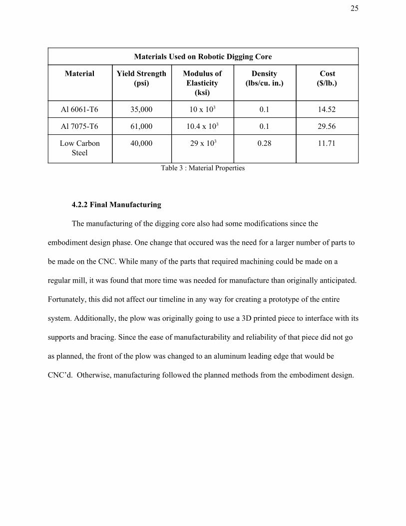
4.2.1 Final Materials and Properties
Overall, the initial plan for materials being used stayed pretty consistent throughout each
of the design phases. However, some parts had to diverge from the initial plan due to the need
for increased robustness in high stress regions. For the bucket design of the digging core, a
higher grade aluminium would be used on high load zones where failure was likely to occur. For
each material used in the design, the necessary properties were logged, such as yield strength and
modulus of elasticity (Table 3).
25
Materials Used on Robotic Digging Core
Material Yield Strength (psi)
Modulus of Elasticity
(ksi)
Density (lbs/cu. in.)
Cost ($/lb.)
Al 6061-T6 35,000 10 x 103 0.1 14.52
Al 7075-T6 61,000 10.4 x 10³ 0.1 29.56
Low Carbon Steel
40,000 29 x 103 0.28 11.71
Table 3 : Material Properties
4.2.2 Final Manufacturing
The manufacturing of the digging core also had some modifications since the
embodiment design phase. One change that occured was the need for a larger number of parts to
be made on the CNC. While many of the parts that required machining could be made on a
regular mill, it was found that more time was needed for manufacture than originally anticipated.
Fortunately, this did not affect our timeline in any way for creating a prototype of the entire
system. Additionally, the plow was originally going to use a 3D printed piece to interface with its
supports and bracing. Since the ease of manufacturability and reliability of that piece did not go
as planned, the front of the plow was changed to an aluminum leading edge that would be
CNC’d. Otherwise, manufacturing followed the planned methods from the embodiment design.

26
4.2.3 Bill of Materials
Bill of Materials
Part Name Quantity Cost per
unit Material Vendor Standard
part?
Extruded Aluminum-profile 5 Assorted Length (in ft.) 25 10.35 6061-T6 Al McMaster YES
M5 x 8 Screws 150 0.11 Grade 8 Alloy St McMaster YES
6 in. steel shafts 0.25" 4 0.5 Low Carbon Steel McMaster YES
Diagonal connectors 16 8.15 6061 Al McMaster YES
DUFF-NORTON-TMD02-2906-4 1 381.64 Variable Duff Norton YES
Vertical Brace (2x2x25 cm) 1 182.49 6061-T6 Al McMaster NO
Plow head (4x6x24cm) 1 6061-T6 Al McMaster NO
Right angle brackets 40 6.04 6061-T6 Al ITEM North YES
Straight angle brackets 16 9.82 6061-T6 Al ITEM North YES
DUFF-NORTON-LT100-2-200P 1 182.49 Duff Norton YES
BG75x25 1 -donated DunkerMotor YES
Linear Bearings 3 90.55 ITEM North YES
Bearing Shaft 3 6 ITEM North YES
Bearing Clamp 3 5.89 ITEM North YES
Bearing Covers 6 5.89 ITEM North YES
Uprights (15x8x2cm) 2 6061-T6 Al McMaster NO
Arms Plate 2 6061-T6 Al McMaster NO
Keyed shaft (40cm) 1 26.66 Low Carbon St McMaster YES
M3 x 18 9 0.11 Gr 8 Alloy steel McMaster YES
Motor Gears 2 34.68 Low Carbon Steel McMaster YES
Wall Mount Bearings .25" ID 2 11.48 McMaster YES
Shaft Collars 2 15.28 Low Carbon Steel McMaster YES
Bucket Flat Sheet 1 6061-T6 Al McMaster NO
Bucket Mount 1 7075-T6 Al McMaster NO
Dogbone linkages bent 2 8 7075-T6 Al McMaster NO
Dogbone linkages straight 2 8 7075-T6 Al McMaster NO
Total Cost of Various Aluminium 1 548.96
TOTAL 2633.14
Table 4: Bill of Materials

27
4.3 Part Drawings
The following part drawings include the bucket (Figure 18), the bucket mount piece
(Figure 19), the bucket shaft upright (Figure 20), and the plow brace (Figure 21).
Figure 18 : Bucket Drawing

28
Figure 19 : Bucket Mount Drawing
Figure 20 : Bucket Upright Drawing

29
Figure 21 : Plow Brace Drawing

30
4.4 Assembly Drawings
Assembly drawings are provided for the bucket system (Figure 22), the plow system
(Figure 23), and the entire digging core (Figure 24). For completeness, a drawing of the entire
lunar robot is included in Appendix A.
Figure 22 : Bucket Assembly Drawing

31
Figure 23 : Plow Assembly Drawing
Figure 24 : Digging Core Assembly Drawing

32
Chapter 5: Testing
5.1 Unloaded Test
5.1.1 Test Setup
For the bucket assembly, the actuator linkage connections were assembled and attached
to the end of the actuator to test the link motion and ensure the bucket would act as designed. For
the plow system, everything was assembled and attached to the robot frame. The frame was
moved to the end of a table in order for the plow to overhang as if the robot was in its starting
position at the beginning of a competition run.
5.1.2 Test Results
When the bucket actuator extended halfway through its intended length, the links made
contact with the actuator shaft and that resulted in one of the linkage connection shafts to fail
(Figure 25).
Figure 25 : Aluminum Shaft Post-Test
When the plow was overhanging the table, there were some clear bracing issues. Without
adding any load to the front of the plow, it was overhanging its intended position and was not
parallel to the ground. When load was applied, serious bending and twisting occured along the
horizontal brace connecting the plow to the linear bearings.

33
5.1.3 Redesign
In order to fix the linkage connection system, bushings were added to each side of the
actuator shaft (Figure 26). The test was done again and the links no longer made contact with the
actuator, resulting in smooth motion.
Figure 26 : Bushings Added To The Shaft
Also, the 6061-T6 aluminum shaft that failed was replaced by a shaft made of 7075-T6
aluminum to further reduce the probability of shaft failure. The shear stress was calculated again
for the new material (17) and this increased the factor of safety to 2.06 (18).
(17).55(S) .55(420.58 Mpa) 31 MP aτ = 0 = 0 = 2
(18)F .06S = τ calculated
τ theoretical = 112 MP a231 MP a = 2
In order to reduce the bending that was occuring with the plow, the decision was made to
take the third bearing in the back and flip it 180 degrees (Figure 27). This orientation required
the actuator structure to change in length and some of the plow supports to be recut. Overall, this
improved the assembly but still did not meet the plow’s expectations. Additional bracing was
then added to the back of the plow and attached to a more static part of the assembly (Figure 27).

34
When a force was applied to the front of the plow, the bending was barely noticeable and the
plow bracing held up better than the original design.
Figure 27 : Plow Redesigns Drawing
5.2 Loaded Test
5.2.1 Test Setup
The goal of this secondary test was to perform a mock competition run of all the systems
and systematically check for underperforming areas. The full robot was placed in a mock area
filled with regular sand and small rocks to simulate gravel. The following areas would be
examined as part of the loaded test: plow depth, bucket penetration, plow width, structural
stability, and quality of dump. Where possible, quantitative data was collected but qualitative
results were accepted if needed.

35
5.2.2 Test Results
For it being the first official live run, the loaded test was a success. The loaded test
proved that plowing a significant amount of Regolith can be achieved. During the test, a plow
depth of 9.6 cm was recorded (Figure 28). While slightly smaller than the goal of 10 cm, this is
expected to meet the goal once the robot’s driving ability improves. Based on the wake of the
plow, it did clear a path equal to the full width of the robot, which allowed for the most stable
digging platform. It was also discovered that the plow could also used while traversing through
the obstacle area of the arena to move large rocks or fill craters (Figure 29).
Figure 28 : First pass at plow usage

36
Figure 29 : Rock pushed with plow
The bucket system was able to dig material and dump. However, reaching a lower depth
while digging was not as successful as planned due to instability in the bucket system. If the
excavator-like motion did not work properly, a skimming style could be utilized successfully.
5.2.3 Redesign
An important issue that was found was when the robot digged it flexed outward causing
the uprights carrying electronic equipment to flex inward, which created the risk of the upright
bars interfering with the bucket system. In the design, the bucket was made to fit inside of the
frame and proper cross bracing would be difficult because it would be in the bucket’s trajectory.
The planned fix for this scenario was some creative fitting of a cross brace that would double as
a physical stop for the bucket so if the software were to fail, it would not rip itself apart. This
cross brace is positioned so it will not interfere with the designed digging cycle. Another issue
that arose was that the plow suffered more vertical force than originally thought. This caused the

37
aluminium shaft holding the actuator to bend and deform (Figure 30). A quick fix was devised to
replace the shaft with carbon steel so deformation did not occur again.
Figure 30 : Shaft bent by actuator
Chapter 6: Discussion
Based on the results of initial testing, it has been determined that the digging core is
functional and will be ready to run for competition. The design requirements laid out in the rules
of the competition as well as set by the team were met or were deemed acceptable. In
comparison to last year’s digging design, this year’s is much improved in all areas. In regards to
the design requirements, it fits within the size constraints, it weighs about 25 kg which is less
than the 30 kg goal, and has the ability to reach low depths while digging. Further improvements
to the design over the weeks leading up to the competition will allow these features to succeed
even more.
During this design process, a lot was learned about designing a dynamic system utilizing
linear bearings. This is a product that was unfamiliar to the team before so there was a learning
curve for proper utilization. The first piece of knowledge learned was how important it is to
couple bearings. The initial design had all three bearings on the same side of the plow assembly.
It was found that this configuration caused the system to have excessive slack, making it

38
unusable. A redesign was done by flipping a bearing and creating a coupling effect. Another
lesson learned was how dangerous an unsupported moment can be on a system. Before adding
the new supports to the system, the plow suffered from the high force of initial impact where it
would cause rotation about the bearings, leading to concentrated stress on specific parts on the
bearings.
Chapter 7: Conclusion
The design process was used when designing this robotic mining digging core. During
the concept phase, a number of interesting concepts were deliberated on and tested. Ultimately, it
was decided to focus on a design that attempted to combine two mining operations: a plowing
phase and a digging phase. The embodiment design period was focused on creating a more
complete design as well as a focus on where failure might occur. Finally, in the detail design
phase, the primary focus was finalizing the design itself and working on redesigns for any
problems that arose while testing. Integration with other parts of the robot was also an important
factor during this phase. Overall, each phase of our design brought the design closer to its end
and brought better understanding of what areas of the system would cause issues as well as how
to properly plan and mitigate them. On that note, the robotic digging core that was designed will
compete in the NASA Robotic Mining Competition in May of 2018.

39
References
Avant Tecno (2018,April 22 Retrieved) Snow Plow Retrieved from
http://www.greenindustrypros.com/product/12082215/avant-tecno-usa-avant-tecno-snow-
plow
Budynas, Richard. G. and Nisbett, Keith. J (2014) Shigley’s Mechanical Engineering Design.
New York, New York:McGraw Hill
Dieter, George. E. and Schmit, Linda. C. (2013) Engineering Design. New York, New
York:McGraw Hill
Heiney, Anna. (2016,October 3) RASSOR, MARCO POLO Demonstrate Resource Utilization on
Mars Retrieved from
https://blogs.nasa.gov/kennedy/2016/10/03/rassor-marco-polo-demonstrate-reso
urce-utilization-on-mars/
Heiney, Anna (March 21,2018) RMC- About the Competition Retrieved from
https://www.nasa.gov/offices/education/centers/kennedy/technology/nasarmc/about
ThyssenKrupp Robins Mining Equipment. (2010,August 10). Retrieved from
http://www.krupprobins.com/Gallery/Mining%20Gallery/mininggallery.html

40
Appendix A - Full Robot Drawing