Embed Size (px)
DESCRIPTION
robot
Citation preview

1
Robot, RRS, RCS

2
1. What is Robot??
2. Applications of the Robots.
3. Automotive Industrial Robots.
4. Singularity Error
5. Selection Criteria in BIW Lines
6. RRS and RCS.
7. What is the difference between different controllers??
8. What are the attributes we give while doing OLP and what are their significance??
9. What info we store in .src and .dat files (Downloads from Robcad)??
10.What are $config.dat and $machine.dat??
11.What are Humming Bird and Exceed??
Contents

3
What is Robot??
A Robot is a reprogrammable, multi-functional
manipulator designed to move material, parts, tools,
or specialized devices through variable programmed
motions for the performance of a variety of tasks.

4
Mobile. The interconnection structure of the kinematic chain
is that of two or more wheels connected to the same base.
The base itself can, in turn, carry a kinematic chain too.
Serial. The interconnection topology of the kinematic
chains is a chain without loops or without multiple
branches.
Humanoid. The interconnection structure of the
kinematic chain is a tree.
Parallel. The interconnection structure of the kinematic chain
consists of two "platforms" connected by a number of “legs” in
parallel. These legs often have identical (mostly serial)
kinematic structures.
Types of Robots on the basis of construction
5
1. Cartesian Robot (Gantry Robot)
Three linear joints provide the three axes of motion and define the x, y and z planes.
This robot is suited for pick and place applications where there are no orientation requirements
Industrial Robots
6
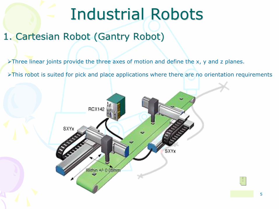
2. SCARA (Selective Compliance Articulated Robot Arm)
The robot has three joints. This is the typical “Assembly and Pick & place" robot.
7
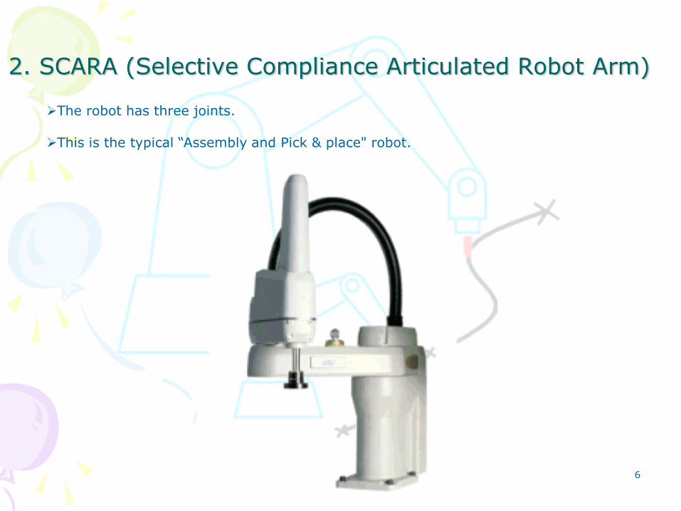
This robot has six independent joints, also called six degrees of freedom.
3. Six axes Robot
8
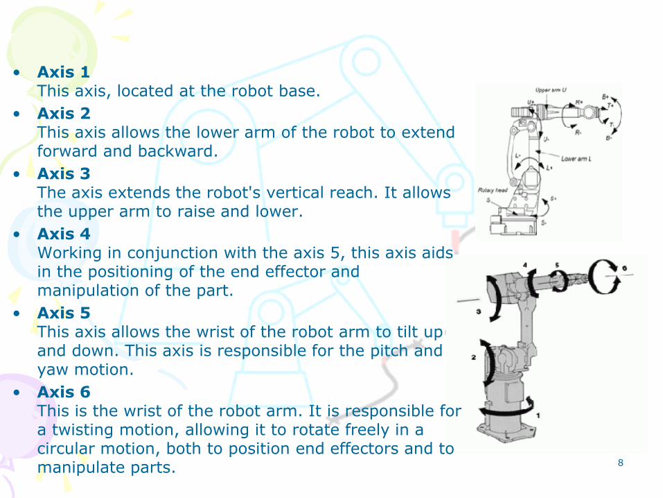
• Axis 1 This axis, located at the robot base.
• Axis 2 This axis allows the lower arm of the robot to extend forward and backward.
• Axis 3 The axis extends the robot's vertical reach. It allows the upper arm to raise and lower.
• Axis 4 Working in conjunction with the axis 5, this axis aids in the positioning of the end effector and manipulation of the part.
• Axis 5 This axis allows the wrist of the robot arm to tilt up and down. This axis is responsible for the pitch and yaw motion.
• Axis 6 This is the wrist of the robot arm. It is responsible for a twisting motion, allowing it to rotate freely in a circular motion, both to position end effectors and to manipulate parts.

9
Robot arms: The robot arm is the part that positions the end effectors.
End effectors: Connects to the robot's arm and functions as a hand.
This part comes in direct contact with the material the robot is
manipulating.
Drive (Motors): is the engine or motor that moves the links into their
designated positions.
Sensors: Allow the robot to receive feedback about its environment.
Controller: The „brain' of the Robot
Main Components of the Robots

10
• Painting
• Arc welding
• Palletizing
• Sealing/dispensing
• Spot welding
• Assembly
• Stud Welding
• Hemming
• Inspection
Major Applications of Robots in Automotive Industries

11
Other Applications
Electron Beam
Flux Cored Welding
Mig Welding
Plasma Cutting
Resistance Welding
Robot Laser Welding
Tig Welding
Welding Automation
Dispensing
Machine Loading
Machine Tending
Material Handling
Order Picking
Packaging
Palletizing
Part Transfer
Pick and Place
Press Tending
Bonding / Sealing
Cleanroom
Deburring
Drilling
Flame Spray
Grinding
Material Removal
Milling
Painting Automation
Polishing
Robotic Assembly
Robotic Coating
Thermal Spray

12
Robot in Transport Position

13
Singularity Error
1. Wrist Singularity
2. Alignment Singularity
Wrist Singularity occurs when the axes of Joints 4 and 6 are aligned.
Alignment Singularity occurs when Joint 6 (wrist) and Joint 1 axes are aligned. (This has not yet occurred in the following figure, but is about to.)
A condition caused by the collinear alignment of two or more robot axes resulting in unpredictable robot motion and velocities
15
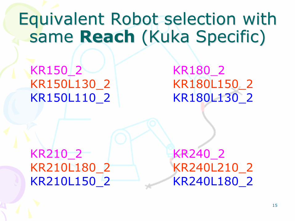
Equivalent Robot selection with same Reach (Kuka Specific)
KR150_2 KR150L130_2 KR150L110_2
KR180_2 KR180L150_2 KR180L130_2
KR210_2 KR210L180_2 KR210L150_2
KR240_2 KR240L210_2 KR240L180_2

16
Equivalent Robot selection with same Payload (Kuka Specific)
KR150_2 KR150L130_2 KR150L110_2
KR180_2 KR180L150_2 KR180L130_2
KR210_2 KR210L180_2 KR210L150_2
KR240_2 KR240L210_2 KR240L180_2

17
REACH (mm) 1100 1300 1500
KUKA
ROBOT
KR 150
KR 150 L130
KR 150 L110
KR 180 KR 180 L150 KR 180 L130
KR 210 KR 210 L180 KR 210 L150
KR 240 KR 240 L 210 KR 240 L180
130
150
180
110
210 240
PAY LOAD (Kg)
SAME REACH ROBOTS SAME PAY LOAD ROBOTS
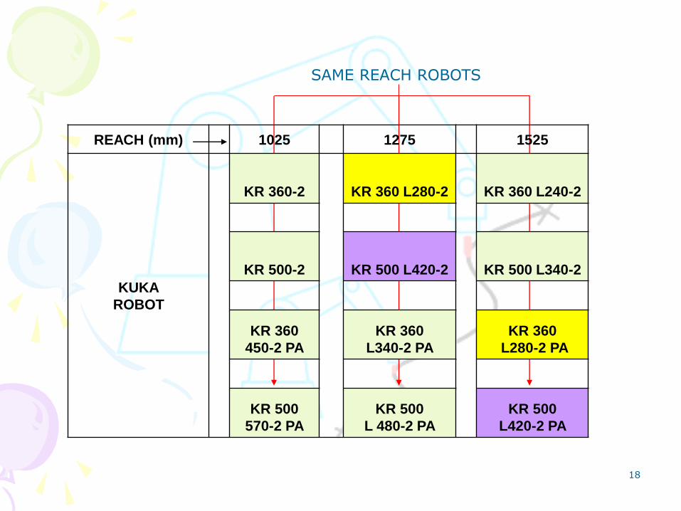
18
REACH (mm) 1025 1275 1525
KUKA
ROBOT
KR 360-2
KR 360 L280-2
KR 360 L240-2
KR 500-2 KR 500 L420-2 KR 500 L340-2
KR 360
450-2 PA
KR 360
L340-2 PA
KR 360
L280-2 PA
KR 500
570-2 PA
KR 500
L 480-2 PA
KR 500
L420-2 PA
SAME REACH ROBOTS

19
Payload Robot ReachKR150_2 1100
KR180L150_2 1300
KR210L150_2 1500
KR180_2 1100
KR210L180_2 1300
KR240L180_2 1500
KR210_2 1100
KR240L210_2 1300
150
180
210
Reach Robot PayloadKR150_2 150
KR180_2 180
KR210_2 210
KR240_2 240
KR150L130_2 130
KR180L150_2 150
KR210L180_2 180
KR240L210_2 210
KR150L110_2 110
KR180L130_2 130
KR210L150_2 150
KR240L180_2 180
1100
1500
1300

20
RRS and RCS
1. Until the early 1990s, the motion behavior of robot simulation often strongly deviated from real behavior.
2. RRS is the interface between Simulating Software and Robot specified Controller
3. Robot Controller Simulation (RCS-) Modules is supplied by controller manufacturers as black-boxes to any simulation system supporting the RRS Interface.
4. Today the RCS-Interface is the world-wide de-facto standard for precise simulation of robot motion behavior.
Figure. 2: The RRS-Interfaces enable to integrate any
robot software into any simulator
• Realistic Robot Simulation • Realistic Controller Simulation

21

22
User activity model
RRS Interface Overview
23
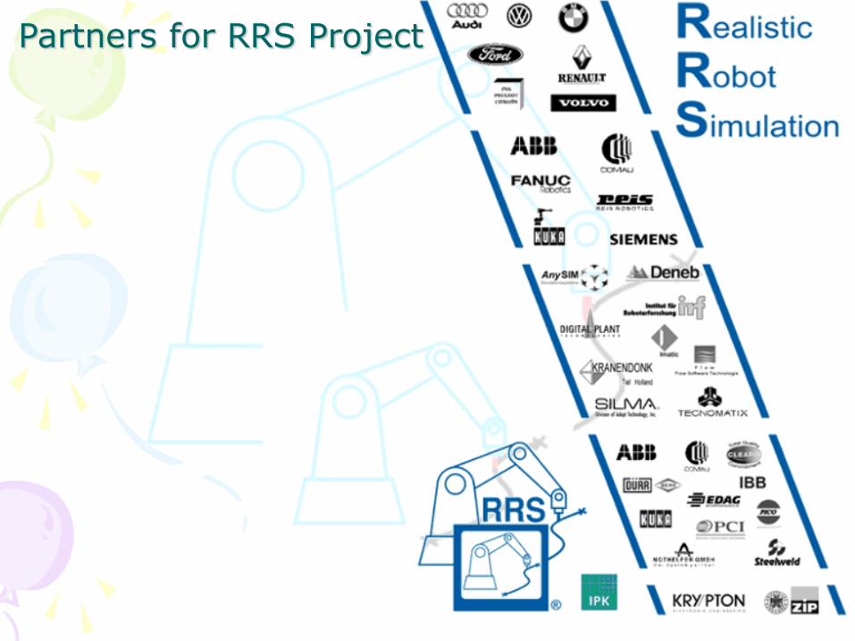
Partners for RRS Project

24
Difference between Default controller and Robot specified Controller
Controller:
•An object able to perform a task which contains logical operations, calculations and
signal handling, but which does not include motion commands.
•A default controller is a Controller model which has only basic attributes which are required to
move the robot in the simulation model and the motion need not to be so exact as the Real-time.
•But a Robot specific controller is integrating the motion controller software of any robot controller
into the simulation system that has the attribute set up which is similar to the actual controller
used in the Real time environment.
•The simulation will be as exact as the motion that is going to be executed in the plant.
• And so we can directly download the Programs/paths from the simulation software and even we
can adjust the Programs in an interactively and simultaneously.
25
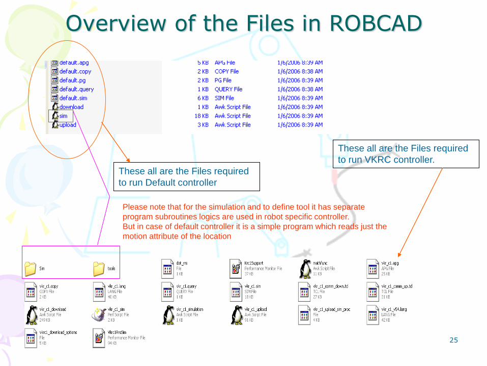
These all are the Files required
to run Default controller
These all are the Files required
to run VKRC controller.
Please note that for the simulation and to define tool it has separate
program subroutines logics are used in robot specific controller.
But in case of default controller it is a simple program which reads just the
motion attribute of the location
Overview of the Files in ROBCAD
26
What are the attributes we give while doing OLP and what are their
significance??
Tool & Base
Motion Type: Joint/Linear/Circular
Accuracy Profile
Tool Type: External/Mounted
Configuration: status and turns
Load Data
27
Process Paths:
The TCP is measured from the flange of the robot and BASE is car origin measured w.r.t robot base.
E.g. Spot/stud Welding, Arc Welding, Hemming,
In case of External TCP, it is measured from the base of the robot and Base is Car origin measured w.r.t
Robot Flange.
E.g. Stationary Spot/stud Weld, Gluing, Clinching,
Handling Path:
We use TCP at the top of the fixed pin of gripper.
Parallel to robot flange axis and co-ordinates are w.r.t. Robot Flange.
For material handling equipment, Robot base will be taken as BASE.
For fixtures, BASE will be at Car origin.
Note: These definitions may vary with OEM to OEM.
General TOOL and BASE Definitions

28
Motion Type
It is the fastest path (Takes minimum time).
TCP movements are not defined.
All the joints accelerates and decelerates at the same time.
Joint will move in one direction only.
It is preferred to use in all via location.
1. Joint Motion:
2. Linear Motion: It is the shortest path (Takes maximum time).
TCP movements are in a straight line.
All the joints accelerates and decelerates independently.
Joint may not move in one direction.
It is preferred to use at process locations.
3. Circular Motion:
TCP moves in an arc.
Can be useful in the processes like Hemming, Glue, Arc Welding Etc.
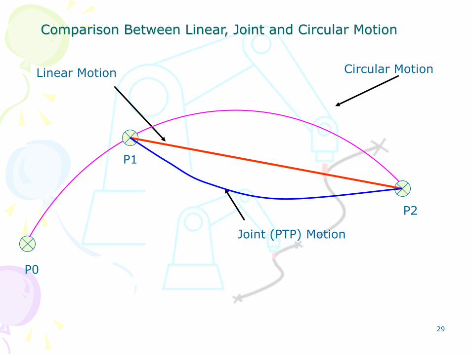
29
Linear Motion
Joint (PTP) Motion
P1
P2
Circular Motion
Comparison Between Linear, Joint and Circular Motion
P0

30
Accuracy
Flyby means that the controller can look ahead and take into account more
than the current target when planning a path and calculating robot‟s motion.
The biggest advantage of the flyby mode is that the corners can be rounded to
maintain a constant speed.
It is the amount by which the TCP will reach to each programmed location. For Ex. If
it is 0% than TCP will reach and touch to each location and if its 100% it will do the
maximum approximation (for clarification pls see the images)
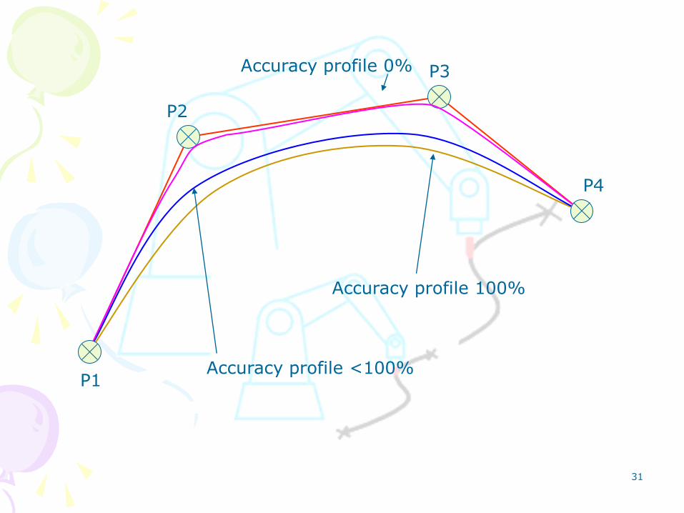
31
P1
P2
P3
P4
Accuracy profile 100%
Accuracy profile 0%
Accuracy profile <100%

32
Without approximate positioning (Accuracy Profile 0%) (No Flyby)
With approximate positioning (Accuracy Profile 100%) (Max Flyby)
P1 P2 P3 P4
Vprog
Vprog
P1 P2 P3 P4
Time (s)
Time (s)
Ve
loc
ity
Ve
loc
ity
5 10 15 20 25 30
5 10 15 20 25 30
Time Study for Approximate positioning.
33
Tool Type
Normally Tool are of two types:
– Basic TCPF • In which the TCPF has been defined at the tool mounted
on the Robot, and the Robot will move to match the Target with the TCPF defined.
– External TCPF • The work piece is mounted on the robot, and the tool is
stationary (external) to the robot.
• Such a TCPF definition is used in case of gluing and static Spot welding.

34
Load Data
In order to maintain the Simulation accordance with the Real time model the Load data value must match with the Simulation data.
The Mass, Centre of gravity and M.I. w.r.t. Robot flange of the tool mounted must be defined in Load data.
In the absence of Load data the robot will move with full payload value which results in wrong Cycle time calculation.
35
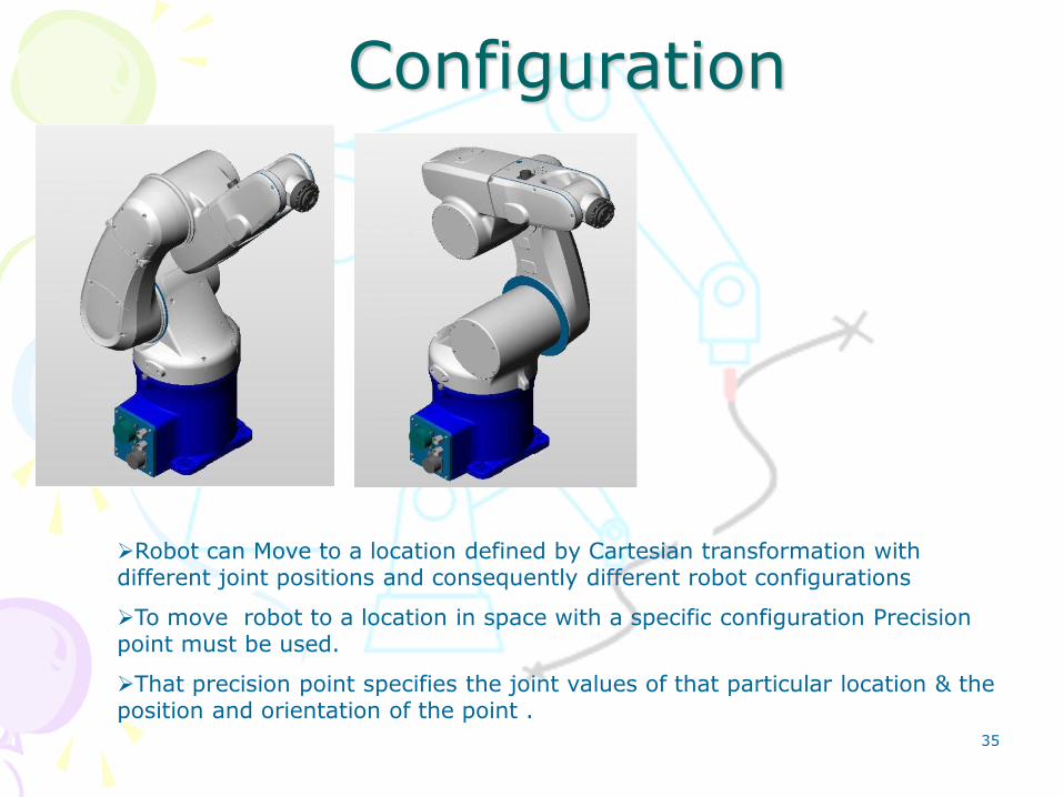
Configuration
Robot can Move to a location defined by Cartesian transformation with different joint positions and consequently different robot configurations
To move robot to a location in space with a specific configuration Precision point must be used.
That precision point specifies the joint values of that particular location & the position and orientation of the point .

36
What info we store in .src and .dat files??
SRC
The SRC file is where all the "executable" code resides like Tool, Base, Motion and
Accuracy Profile.
In SRC file, we need to make sure to set active Tool, Base, and Speed (Joint speed and
linear speed both) before we actually perform any motion commands.
It contains the sequence of the program with attributes assigned for the points.
DAT
The DAT file is where the persistent variables are stored, like point positions (usually
E6POS or E6AXIS variable types).
It contains list of all the points i.e. via and process, and its coordinate values, tool and base
frame assigned for the points.

37
.src File

38
.dat File

39
What are $config.dat and $machine.dat
config.dat In this, we store TOOL- and BASE- DATAS, LOAD-DATAS and all moving parameters we
use.
I/O signals are also declared here. But pay attention, each costumer have his own
modification.
machine.dat It contains DATAS given by the Robot-provider. In this data You find all parameters which
define the robot-type. Each type needs his own special data.
Do not change this data without permission from the provider, especially the typical movement
parameters.
Some parameters, for example IN/OUT-signals for safe-robot, You can change according to
the needed configuration.
The function of this machine.dat is the same like the controller in Robcad. It contains the
typical movement behavior of the robot system.

40
What are Humming Bird and Exceed
Hummingbird / exceed is something that sits between windows and Robcad.
RobCAD originally ran on unix, but when they released the Windows version of
Robcad they had not rewritten robcad, they ported it instead (exceed acts like a unix
environment for Robcad to run on).
If you don‟t have exceed, current versions of robcad will not run on windows
based Systems.

41
Major Robot Manufacturers

42
References
• www.Realistic-Robot-Simulation.org
• www.Robots.com
• www.learnaboutrobots.com
• Kuka Robot Programming Handbook
• www.kuka.com
• www.americanrobotcorporation.com

43
Thank You!!


![YAMAHA ROBOT CONTROLLER SUPPORTING ......YAMAHA ROBOT CONTROLLER SUPPORTING SOFTWARE E64-P-Ver. 1.13.0 POPCOM Contents: [1] Installation Guide [2] Backup current data from robot controller](https://img.dokumen.tips/doc/110x75/5f0b5fca7e708231d4303425/yamaha-robot-controller-supporting-yamaha-robot-controller-supporting-software.jpg)


![Micro Controller Based Fire Fighting Robot[1]](https://img.dokumen.tips/doc/110x75/55205991497959842f8b4a5b/micro-controller-based-fire-fighting-robot1.jpg)