Embed Size (px)
Citation preview
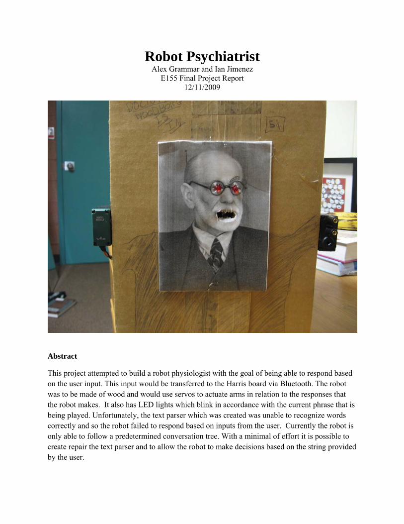
Robot Psychiatrist Alex Grammar and Ian Jimenez
E155 Final Project Report 12/11/2009
Abstract
This project attempted to build a robot physiologist with the goal of being able to respond based on the user input. This input would be transferred to the Harris board via Bluetooth. The robot was to be made of wood and would use servos to actuate arms in relation to the responses that the robot makes. It also has LED lights which blink in accordance with the current phrase that is being played. Unfortunately, the text parser which was created was unable to recognize words correctly and so the robot failed to respond based on inputs from the user. Currently the robot is only able to follow a predetermined conversation tree. With a minimal of effort it is possible to create repair the text parser and to allow the robot to make decisions based on the string provided by the user.
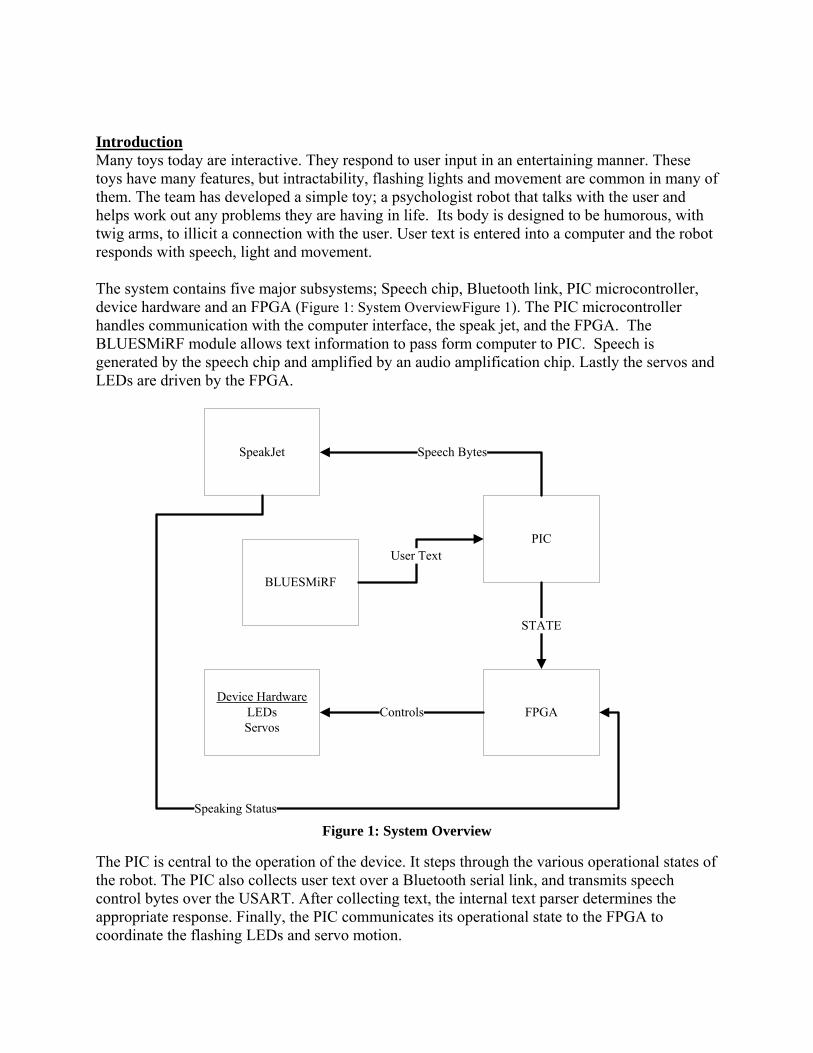
Introduction Many toys today are interactive. They respond to user input in an entertaining manner. These toys have many features, but intractability, flashing lights and movement are common in many of them. The team has developed a simple toy; a psychologist robot that talks with the user and helps work out any problems they are having in life. Its body is designed to be humorous, with twig arms, to illicit a connection with the user. User text is entered into a computer and the robot responds with speech, light and movement. The system contains five major subsystems; Speech chip, Bluetooth link, PIC microcontroller, device hardware and an FPGA (Figure 1: System OverviewFigure 1). The PIC microcontroller handles communication with the computer interface, the speak jet, and the FPGA. The BLUESMiRF module allows text information to pass form computer to PIC. Speech is generated by the speech chip and amplified by an audio amplification chip. Lastly the servos and LEDs are driven by the FPGA.
PIC
FPGA
SpeakJet
BLUESMiRF
STATE
Speech Bytes
User Text
Device HardwareLEDsServos
Controls
Speaking Status
Figure 1: System Overview
The PIC is central to the operation of the device. It steps through the various operational states of the robot. The PIC also collects user text over a Bluetooth serial link, and transmits speech control bytes over the USART. After collecting text, the internal text parser determines the appropriate response. Finally, the PIC communicates its operational state to the FPGA to coordinate the flashing LEDs and servo motion.
The LED’s are powered by a single output pin of the FPGA. The FPGA the negative side of the diode is tied to ground and the other tied to the output pin. This allowed for the simple manipulation of the lights state with a single on/off bit.
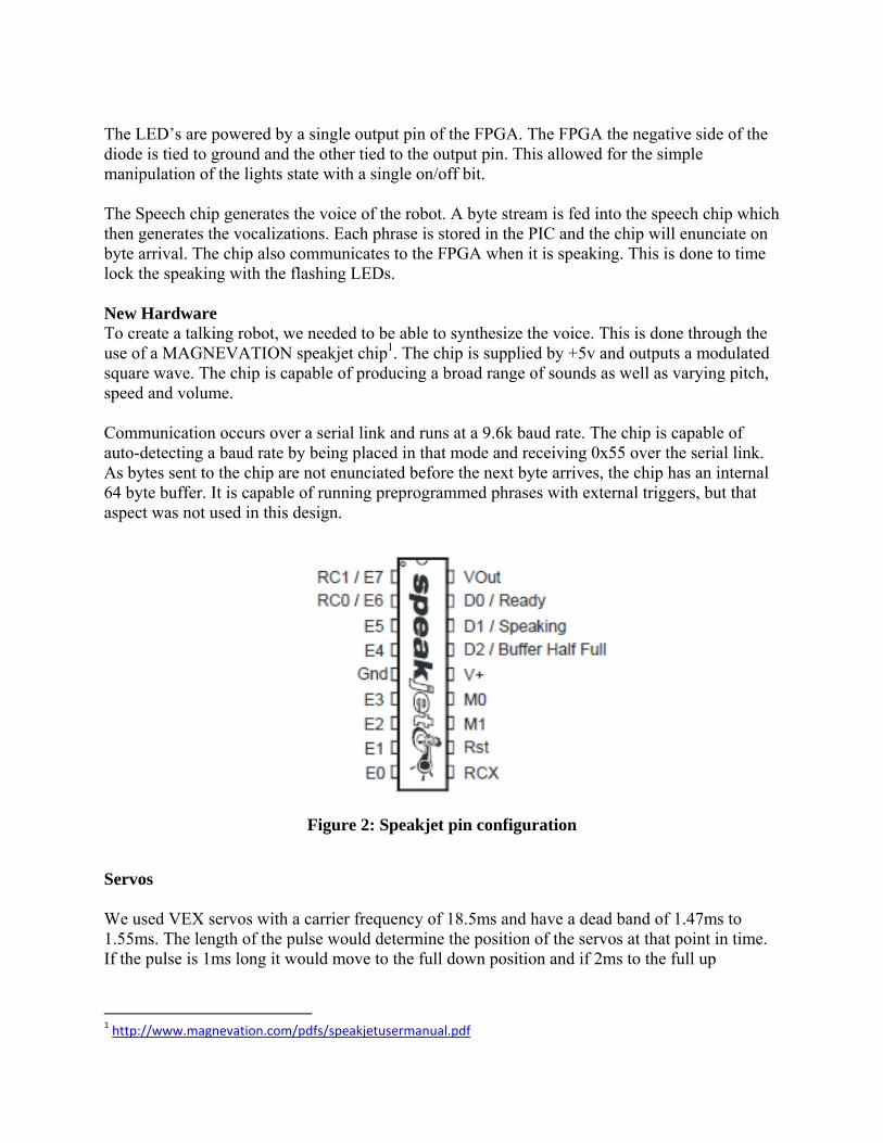
The Speech chip generates the voice of the robot. A byte stream is fed into the speech chip which then generates the vocalizations. Each phrase is stored in the PIC and the chip will enunciate on byte arrival. The chip also communicates to the FPGA when it is speaking. This is done to time lock the speaking with the flashing LEDs. New Hardware To create a talking robot, we needed to be able to synthesize the voice. This is done through the use of a MAGNEVATION speakjet chip1. The chip is supplied by +5v and outputs a modulated square wave. The chip is capable of producing a broad range of sounds as well as varying pitch, speed and volume. Communication occurs over a serial link and runs at a 9.6k baud rate. The chip is capable of auto-detecting a baud rate by being placed in that mode and receiving 0x55 over the serial link. As bytes sent to the chip are not enunciated before the next byte arrives, the chip has an internal 64 byte buffer. It is capable of running preprogrammed phrases with external triggers, but that aspect was not used in this design.
Figure 2: Speakjet pin configuration
Servos We used VEX servos with a carrier frequency of 18.5ms and have a dead band of 1.47ms to 1.55ms. The length of the pulse would determine the position of the servos at that point in time. If the pulse is 1ms long it would move to the full down position and if 2ms to the full up
1 http://www.magnevation.com/pdfs/speakjetusermanual.pdf
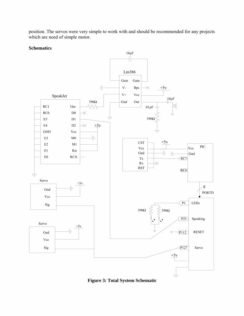
position. The servos were very simple to work with and should be recommended for any projects which are need of simple motor. Schematics
RC1
RC0
Out
D0
E5 D1
E4 D2
GND Vcc
E3 M0
E2 M1
E1
E0
Rst
RCX
+5v
SpeakJet
Gain Gain
V- Bps
Out
V+ Vcc
Gnd
Lm386
+5v
CSTVccGndTxRx
RST
+5v
RC7
RC6
PICVccGnd
8PORTD
P1
P25
P112
P127
LEDs
Speaking
RESET
Servo
+5v
Gnd
Vcc
Sig
Servo+5v
Gnd
Vcc
Sig
Servo+5v
390Ω
390Ω 390Ω
390Ω
.01µF
10µF
10µF
Figure 3: Total System Schematic
FPGA Design
In this project we chose to utilize the FPGA as a storage device to hold large blocks of ROM which would be hold the values required to flash the lights based on the current phrase that was being spoken by the robot. The robot was built to take in an 8 bit value from the PIC and then find the location within the memory block that held the values which were associated with the phrase that was currently being spoken. The servo’s which moved the arms of the robot were move depending on if the speech chip indicated if it was currently talking or not. The movement of the arms would be up when the speaking pin was high and would be placed down otherwise.
The main function of the FPGA was as the storage device of if the lights were going to be flashing or not. In an effort to save space and make it easier to code the large block of memory which was required we slowed the clock speed down from 20MHz to one cycle for every tenth of a second. This allowed us to use a smaller amount of space on the FPGA since the LED’s value was refreshed at such a low rate. We did this with a 22-bit counter which functions to slow the clock to the desired speed since the rest of the control circuit for the LED’s used the most significant bit of the clock. The counter was reset every time that the most significant bit when high to insure that we always got the same period. Although the period was not exactly one tenth of a second it allowed us to avoid large blocks of logic to determine if the counter which slowed the clock was at an exact value and for the purpose of flashing the LED’s the accuracy was sufficient.
One of the major issue of trying to pass specific patterns of lights on the LED’s was the fact that the speech chip we were using held the words in a buffer before saying them and so the current outgoing bit from the PIC for the most part had no relation to the word that was currently being said. So we attempted to synchronize the words based upon the amount of time that the documentation claimed that each sound took to say. Unfortunately, these values appeared to be off. After many attempts it was impossible to figure out why the time calculated from the stat sheet was different than the value which was recorded when one timed a phrase. We instead decided to time all the phrases which our robot said and this allowed for us to implement a system that could provide unique flash patterns for each phrase. The FPGA was also supposed to implement a hold function based on the values stored within the memory block. This was removed due in part the unreliability of the system and the fact that by timing the phrase and programming the flashes a similar look was achieved.
The block which controls the LED’s is made of three main components. The first module the, pntmem block serves to translate the incoming values from the PIC. The second module, mempnt, holds and increments the pointer based on the slowed clock speed but can also accept an incoming pointer values and replace the current pointer value with that. The final block, led0,
checks if the speech chip is speaking and based on that reads LED value to the output from the ROM block, which holds the LED’s status.
The first block functions by storing the pointer addresses in a ROM block which essentially translates the PIC data into pointers. A second module compares the current value to the pervious value and if it is different it flags the set bit making the value from the pointer ROM file the new pointer. The original idea was to implement a second such system for the control of the arms but due to time constraints we were unable to implement this.
The second block is constructed to allow for a settable program counter. A basic counter was going to be used originally but I found that having a settable flip-flop made it much easier to deal with the controls which were required and it would be much harder to try and take the standard counter block and change to being settable.
The final block was the most time consume due in large part to the fact that the block with the LED memory was generated from a large case structure which spanned almost 256 values. Throughout the project we attempted to find a more efficient way of creating the ROM file but a case structure seemed to be just as effective as any other method looked at. The basic code only took a few minutes but to check different light patterns in software took a long time.
The control system that runs the PWM was very similar to the system that ran the LED. Although it lacked the implementation of the memory system it would have been able to had one added extremely quickly but concerns about the amount of memory it would take to store a value of each cycle stopped this from being implemented. Instead the arms were tied to the speaking pin which when high moves the arms to the highest position and when low to the lowest position.
We used VEX servos with a carrier frequency of 18.5ms and have a dead band of 1.47ms to 1.55ms. The length of the pulse would determine the position of the servos at that point in time. If the pulse is 1ms long it would move to the full down position and if 2ms to the full up position. The servos were very simple to work with and should be recommended for any projects which are need of simple motor.
PIC The PIC drives the robot through a series of subroutines that step through a conversation with the user. Our device has an initial startup routine and then runs the chat program. The chat program runs on a finite state machine that first acquires a string from the user, parses it for key words and determines a proper response from the user. Also controlled by the PIC are the phrases used to generate speech.
The startup routine enables the PIC for USART communication. Port C is used for serial communication and was configured for both input and output. Initially the USART is configured
for a 115.2k baud rate. This is to communicate with the BLUEMiRF Bluetooth module. The last function of the startup routine is to call talkProgram and start the interaction routine.
The first step in the communication routine is to get a string from the user. This is done in two steps. First, the PIC calls getChar which waits until the byte receive complete flag is thrown. The contents of the RX receive register are returned. This function is called by the getString function repeatedly. Characters are collected and stored in inputBuffer until the user sends an enter stroke.
After collecting a string, the array has a space character added to the end. This is to help the parser. Stepping through the string a temporary array, word, is assembled from the cahrecters between spaces. Each word is then compared to several key words using strcmp. Strcmp returns a 0 if there is a match between the two strings passed to it. The word is then checked against a list of keywords. The keywords are geared towards positive and negative emotions tied to the sentence, giving a word a polarity. A word is also checked if it is “not” as that shifts the polarity of the following word. A word with a positive or negative polarity increments a counter for that type.
This process allows the user to interact with the robot over a serial link. The chat program comprises this acquisition process, as well as a directed dialogue tree. Each phrase is pre-stored as a char array in the PIC with the length of the array stored as the first byte. sayPhrase takes in a character corresponding to the phrase needed to be said. The function runs a for loop that sends out each character through printf. The most important aspect of sayPhrase is the multiplexing of the USART. Bluetooth needs 115.2k while the speechjet runs at 9.6k. SPBRG needs to be changed that the start and end of the function. The baud rate of the chip can be changed, but for convenience it was simpler to change rates on the PIC side. The last part of sayPhrase is to output which phrase is being said to PORTD. The phrase is labeled with char and can be written to a port. This port is connected to the FPGA to flash the lights.
Lastly the PIC uses these routines to step through the chat program. The chat function is called and the greeting message is played. The function loops until an exit flag is thrown. The finite state machine first acquires a string from the user, parses it if needed and then steps through a dialogue tree. This tree controls which phrase is played and if user input is needed. When it reaches the end of the tree, the exit flag is thrown and the program exits.
Results The robot had minor success. The Bluetooth, servos, flashing LEDS and speech chip function as specified in the proposal. Currently, the problem lies in generating a proper response to the user input. The issue has been traced down to the string compare functions running in the text parser. Matching strings are not being recognized and the robot is only responding with a neutral statement. This indicates that the polarity counters are not being incremented appropriately. In terms of the humor factor, the robot was well received

Parts List Servos…………….0$ Harris Board………0$ SpeakJet…………..0$ Audio Amplifier….0$ BLUESMiRF……..0$ LEDs……………...0$
Appendix
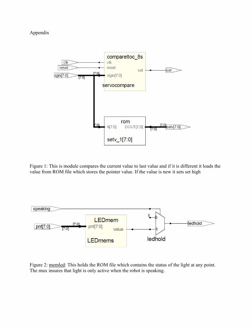
Figure 1: This is module compares the current value to last value and if it is different it loads the value from ROM file which stores the pointer value. If the value is new it sets set high
Figure 2: memled: This holds the ROM file which contains the status of the light at any point. The mux insures that light is only active when the robot is speaking.
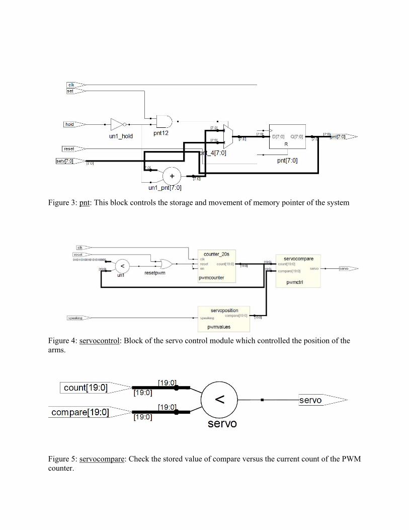
Figure 3: pnt: This block controls the storage and movement of memory pointer of the system
Figure 4: servocontrol: Block of the servo control module which controlled the position of the arms.
Figure 5: servocompare: Check the stored value of compare versus the current count of the PWM counter.
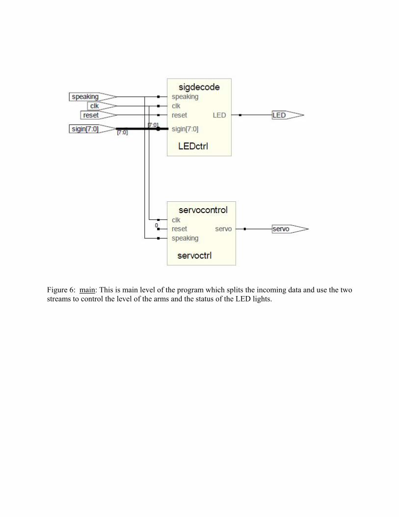
Figure 6: main: This is main level of the program which splits the incoming data and use the two streams to control the level of the arms and the status of the LED lights.
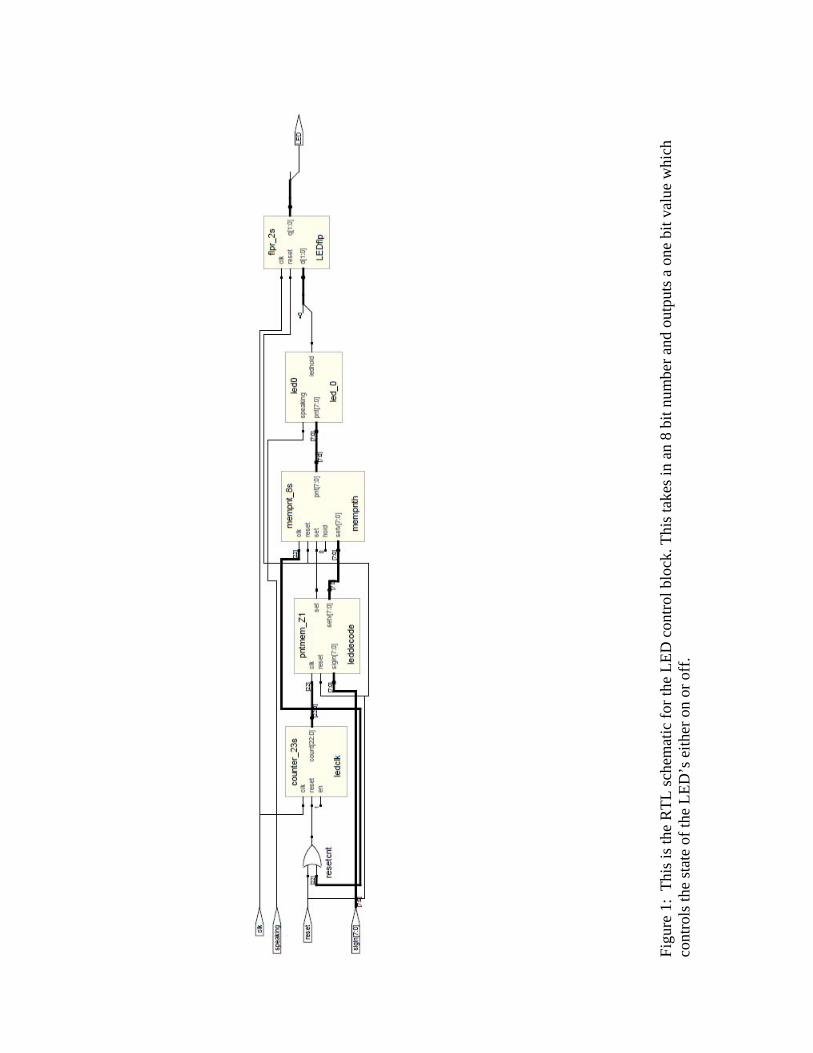
Fi
gure
1:
This
is th
e R
TL sc
hem
atic
for t
he L
ED c
ontro
l blo
ck. T
his t
akes
in a
n 8
bit n
umbe
r and
out
puts
a o
ne b
it va
lue
whi
ch
cont
rols
the
stat
e of
the
LED
’s e
ither
on
or o
ff.
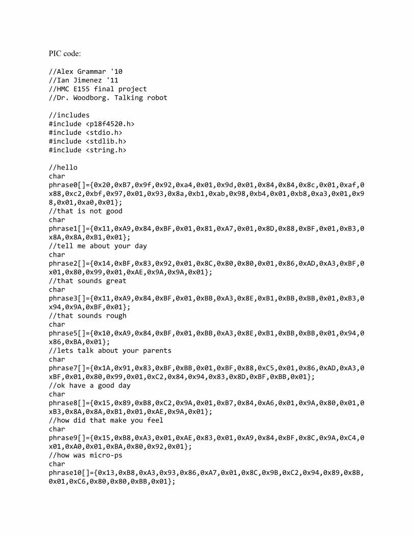
PIC code: //Alex Grammar '10 //Ian Jimenez '11 //HMC E155 final project //Dr. Woodborg. Talking robot //includes #include <p18f4520.h> #include <stdio.h> #include <stdlib.h> #include <string.h> //hello char phrase0[]=0x20,0xB7,0x9f,0x92,0xa4,0x01,0x9d,0x01,0x84,0x84,0x8c,0x01,0xaf,0x88,0xc2,0xbf,0x97,0x01,0x93,0x8a,0xb1,0xab,0x98,0xb4,0x01,0xb8,0xa3,0x01,0x98,0x01,0xa0,0x01; //that is not good char phrase1[]=0x11,0xA9,0x84,0xBF,0x01,0x81,0xA7,0x01,0x8D,0x88,0xBF,0x01,0xB3,0x8A,0x8A,0xB1,0x01; //tell me about your day char phrase2[]=0x14,0xBF,0x83,0x92,0x01,0x8C,0x80,0x80,0x01,0x86,0xAD,0xA3,0xBF,0x01,0x80,0x99,0x01,0xAE,0x9A,0x9A,0x01; //that sounds great char phrase3[]=0x11,0xA9,0x84,0xBF,0x01,0xBB,0xA3,0x8E,0xB1,0xBB,0xBB,0x01,0xB3,0x94,0x9A,0xBF,0x01; //that sounds rough char phrase5[]=0x10,0xA9,0x84,0xBF,0x01,0xBB,0xA3,0x8E,0xB1,0xBB,0xBB,0x01,0x94,0x86,0xBA,0x01; //lets talk about your parents char phrase7[]=0x1A,0x91,0x83,0xBF,0xBB,0x01,0xBF,0x88,0xC5,0x01,0x86,0xAD,0xA3,0xBF,0x01,0x80,0x99,0x01,0xC2,0x84,0x94,0x83,0x8D,0xBF,0xBB,0x01; //ok have a good day char phrase8[]=0x15,0x89,0xB8,0xC2,0x9A,0x01,0xB7,0x84,0xA6,0x01,0x9A,0x80,0x01,0xB3,0x8A,0x8A,0xB1,0x01,0xAE,0x9A,0x01; //how did that make you feel char phrase9[]=0x15,0xB8,0xA3,0x01,0xAE,0x83,0x01,0xA9,0x84,0xBF,0x8C,0x9A,0xC4,0x01,0xA0,0x01,0xBA,0x80,0x92,0x01; //how was micro‐ps char phrase10[]=0x13,0xB8,0xA3,0x93,0x86,0xA7,0x01,0x8C,0x9B,0xC2,0x94,0x89,0x8B,0x01,0xC6,0x80,0x80,0xBB,0x01;
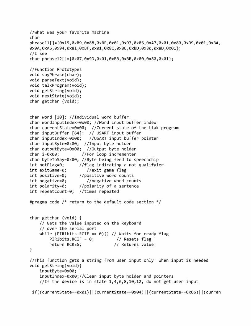
//what was your favorite machine char phrase11[]=0x19,0xB9,0x88,0xBF,0x01,0x93,0x86,0xA7,0x01,0x80,0x99,0x01,0xBA,0x9A,0xA6,0x94,0x81,0xBF,0x01,0x8C,0x86,0xBD,0x80,0x8D,0x01; //I see char phrase12[]=0x07,0x9D,0x01,0xBB,0xBB,0x80,0x80,0x01; //Function Prototypes void sayPhrase(char); void parseText(void); void talkProgram(void); void getString(void); void nextState(void); char getchar (void); char word [10]; //Individual word buffer char wordInputIndex=0x00; //Word input buffer index char currentState=0x00; //Current state of the tlak program char inputBuffer [64]; // USART input buffer char inputIndex=0x00; //USART input buffer pointer char inputByte=0x00; //Input byte holder char outputByte=0x00; //Output byte holder char i=0x00; //For loop incrementer char byteToSay=0x00; //Byte being feed to speechchip int notFlag=0; //flag indicating a not qualifyier int exitGame=0; //exit game flag int positive=0; //positive word counts int negative=0; //negative word counts int polarity=0; //polarity of a sentence int repeatCount=0; //times repeated #pragma code /* return to the default code section */ char getchar (void) // Gets the value inputed on the keyboard // over the serial port while (PIR1bits.RCIF == 0) // Waits for ready flag PIR1bits.RCIF = 0; // Resets flag return RCREG; // Returns value //This function gets a string from user input only when input is needed void getString(void) inputByte=0x00; inputIndex=0x00;//Clear input byte holder and pointers //If the device is in state 1,4,6,8,10,12, do not get user input if((currentState==0x01)||(currentState==0x04)||(currentState==0x06)||(curren
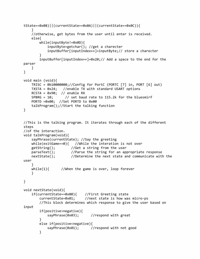
tState==0x08)||(currentState==0x0A)||(currentState==0x0C)) //otherwise, get bytes from the user until enter is received. else while(inputByte!=0x0D) inputByte=getchar(); //get a charecter inputBuffer[inputIndex++]=inputByte;// store a charecter inputBuffer[inputIndex++]=0x20;// Add a space to the end for the parser void main (void) TRISC = 0b10000000;//Config for PortC (PORTC [7] in, PORT [6] out) TXSTA = 0x24; //enable TX with standard USART options RCSTA = 0x90; // enable RX SPBRG = 10; // set baud rate to 115.2k for the bluesmirf PORTD =0x00; //Set PORTD to 0x00 talkProgram();//Start the talking function //This is the talking program. It iterates through each of the different steps //of the interaction. void talkProgram(void) sayPhrase(currentState); //Say the greeting while(exitGame==0) //While the interation is not over getString(); //Get a string from the user parseText(); //Parse the string for an appropriate response nextState(); //Determine the next state and communicate with the user while(1) //When the game is over, loop forever void nextState(void) if(currentState==0x00) //First Greeting state currentState=0x01; //next state is how was micro‐ps //This block determines which response to give the user based on input if(positive>negative) sayPhrase(0x03); //respond with great else if(positive<negative) sayPhrase(0x01); //respond with not good
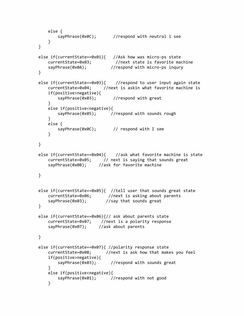
else sayPhrase(0x0C); //respond with neutral i see else if(currentState==0x01) //Ask how was micro‐ps state currentState=0x03; //next state is favorite machine sayPhrase(0x0A); //respond with micro‐ps inqury else if(currentState==0x03) //respond to user input again state currentState=0x04; //next is askin what favorite machine is if(positive>negative) sayPhrase(0x03); //respond with great else if(positive<negative) sayPhrase(0x05); //respond with sounds rough else sayPhrase(0x0C); // respond with I see else if(currentState==0x04) //ask what favorite machine is state currentState=0x05; // next is saying that sounds great sayPhrase(0x0B); //ask for favorite machine else if(currentState==0x05) //tell user that sounds great state currentState=0x06; //next is asking about parents sayPhrase(0x03); //say that sounds great else if(currentState==0x06)// ask about parents state currentState=0x07; //next is a polarity response sayPhrase(0x07); //ask about parents else if(currentState==0x07) //polarity response state currentState=0x08; //next is ask how that makes you feel if(positive>negative) sayPhrase(0x03); //respond with sounds great else if(positive<negative) sayPhrase(0x01); //respond with not good
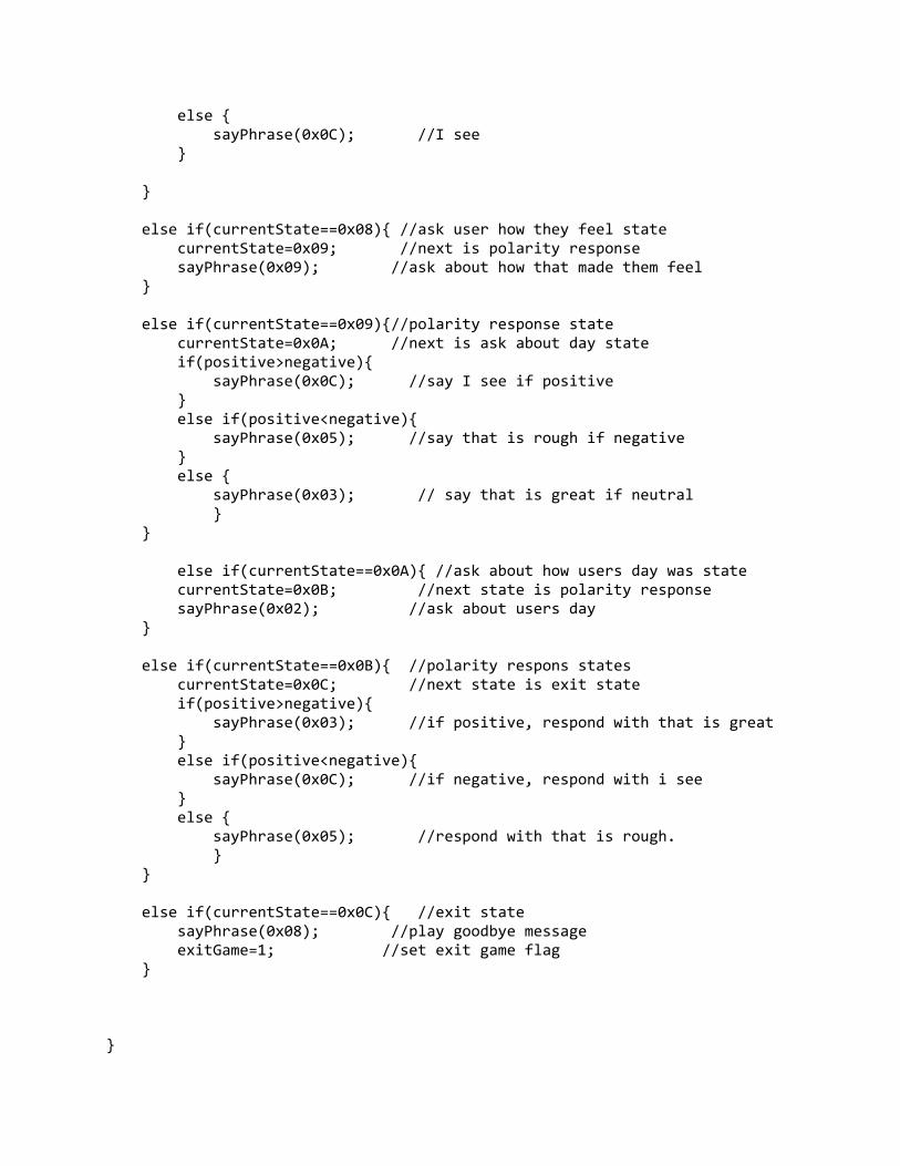
else sayPhrase(0x0C); //I see else if(currentState==0x08) //ask user how they feel state currentState=0x09; //next is polarity response sayPhrase(0x09); //ask about how that made them feel else if(currentState==0x09)//polarity response state currentState=0x0A; //next is ask about day state if(positive>negative) sayPhrase(0x0C); //say I see if positive else if(positive<negative) sayPhrase(0x05); //say that is rough if negative else sayPhrase(0x03); // say that is great if neutral else if(currentState==0x0A) //ask about how users day was state currentState=0x0B; //next state is polarity response sayPhrase(0x02); //ask about users day else if(currentState==0x0B) //polarity respons states currentState=0x0C; //next state is exit state if(positive>negative) sayPhrase(0x03); //if positive, respond with that is great else if(positive<negative) sayPhrase(0x0C); //if negative, respond with i see else sayPhrase(0x05); //respond with that is rough. else if(currentState==0x0C) //exit state sayPhrase(0x08); //play goodbye message exitGame=1; //set exit game flag
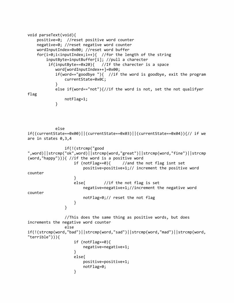
void parseText(void) positive=0; //reset positive word counter negative=0; //reset negative word counter wordInputIndex=0x00; //reset word buffer for(i=0;i<inputIndex;i++) //for the length of the string inputByte=inputBuffer[i]; //pull a charecter if(inputByte==0x20) //If the charecter is a space word[wordInputIndex++]=0x00; if(word=="goodbye ") //if the word is goodbye, exit the program currentState=0x0C; else if(word=="not")//if the word is not, set the not qualifyer flag notFlag=1; else if((currentState==0x00)||(currentState==0x03)||(currentState==0x04))// if we are in states 0,3,4 if(!(strcmp("good ",word)||strcmp("ok",word)||strcmp(word,"great")||strcmp(word,"fine")||strcmp(word,"happy"))) //if the word is a positive word if (notFlag==0) //and the not flag isnt set positive=positive+1;// increment the positive word counter else //if the not flag is set negative=negative+1;//increment the negative word counter notFlag=0;// reset the not flag //This does the same thing as positive words, but does increments the negative word counter else if(!(strcmp(word,"bad")||strcmp(word,"sad")||strcmp(word,"mad")||strcmp(word,"terrible"))) if (notFlag==0) negative=negative+1; else positive=positive+1; notFlag=0;
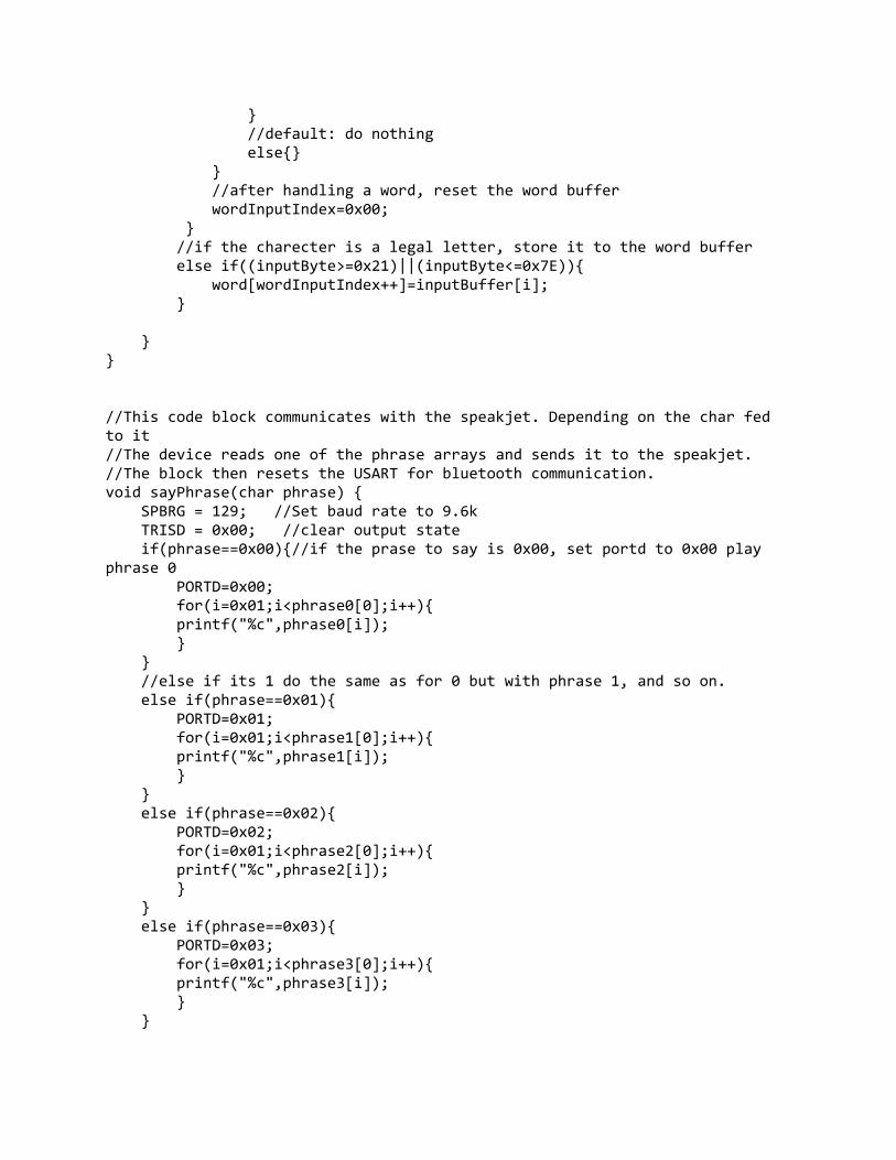
//default: do nothing else //after handling a word, reset the word buffer wordInputIndex=0x00; //if the charecter is a legal letter, store it to the word buffer else if((inputByte>=0x21)||(inputByte<=0x7E)) word[wordInputIndex++]=inputBuffer[i]; //This code block communicates with the speakjet. Depending on the char fed to it //The device reads one of the phrase arrays and sends it to the speakjet. //The block then resets the USART for bluetooth communication. void sayPhrase(char phrase) SPBRG = 129; //Set baud rate to 9.6k TRISD = 0x00; //clear output state if(phrase==0x00)//if the prase to say is 0x00, set portd to 0x00 play phrase 0 PORTD=0x00; for(i=0x01;i<phrase0[0];i++) printf("%c",phrase0[i]); //else if its 1 do the same as for 0 but with phrase 1, and so on. else if(phrase==0x01) PORTD=0x01; for(i=0x01;i<phrase1[0];i++) printf("%c",phrase1[i]); else if(phrase==0x02) PORTD=0x02; for(i=0x01;i<phrase2[0];i++) printf("%c",phrase2[i]); else if(phrase==0x03) PORTD=0x03; for(i=0x01;i<phrase3[0];i++) printf("%c",phrase3[i]);
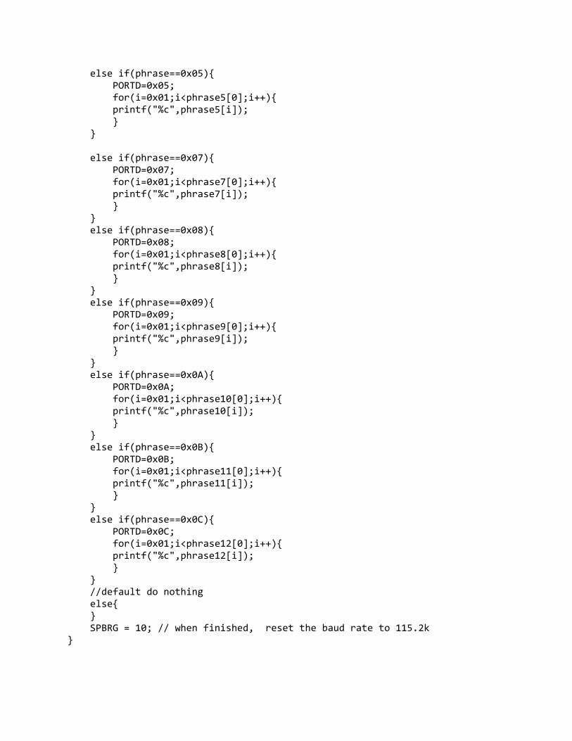
else if(phrase==0x05) PORTD=0x05; for(i=0x01;i<phrase5[0];i++) printf("%c",phrase5[i]); else if(phrase==0x07) PORTD=0x07; for(i=0x01;i<phrase7[0];i++) printf("%c",phrase7[i]); else if(phrase==0x08) PORTD=0x08; for(i=0x01;i<phrase8[0];i++) printf("%c",phrase8[i]); else if(phrase==0x09) PORTD=0x09; for(i=0x01;i<phrase9[0];i++) printf("%c",phrase9[i]); else if(phrase==0x0A) PORTD=0x0A; for(i=0x01;i<phrase10[0];i++) printf("%c",phrase10[i]); else if(phrase==0x0B) PORTD=0x0B; for(i=0x01;i<phrase11[0];i++) printf("%c",phrase11[i]); else if(phrase==0x0C) PORTD=0x0C; for(i=0x01;i<phrase12[0];i++) printf("%c",phrase12[i]); //default do nothing else SPBRG = 10; // when finished, reset the baud rate to 115.2k
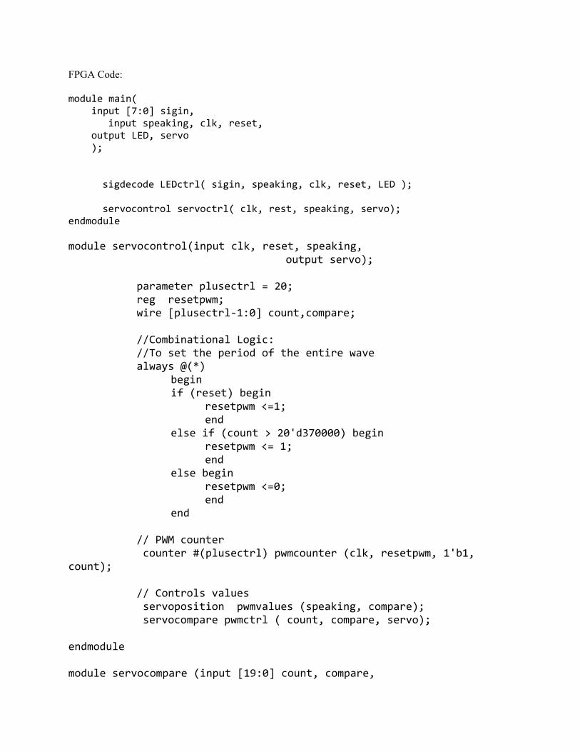
FPGA Code: module main( input [7:0] sigin, input speaking, clk, reset, output LED, servo ); sigdecode LEDctrl( sigin, speaking, clk, reset, LED ); servocontrol servoctrl( clk, rest, speaking, servo); endmodule module servocontrol(input clk, reset, speaking, output servo); parameter plusectrl = 20; reg resetpwm; wire [plusectrl‐1:0] count,compare; //Combinational Logic: //To set the period of the entire wave always @(*) begin if (reset) begin resetpwm <=1; end else if (count > 20'd370000) begin resetpwm <= 1; end else begin resetpwm <=0; end end // PWM counter counter #(plusectrl) pwmcounter (clk, resetpwm, 1'b1, count); // Controls values servoposition pwmvalues (speaking, compare); servocompare pwmctrl ( count, compare, servo); endmodule module servocompare (input [19:0] count, compare,

output reg servo); // This modules comapares the values from compare to count and sees // if the wave should be high. If compare less than or == to count // goes low on reset pulls wave to 1 agian always @ ( * ) begin if ( compare <= count) servo <= 2'b0; else servo <= 2'b11; end endmodule module servoposition (input speaking, output reg [19:0]compare); // While speaking his arms will raise to highest position // Otherwise he moves them to lowest position always @(*) begin if (speaking ) compare <= 20'd40000; else compare <= 20'd20000; end endmodule module LEDmem ( input [7:0] pnt, output reg value); // mem block to control the period of time that each light is on // should be used with .1 s always @ ( * ) case( pnt ) // START PHRASE 0 8'h00: value <= 1'b0; 8'h01: value <= 1'b1; 8'h02: value <= 1'b0; 8'h03: value <= 1'b1; 8'h04: value <= 1'b0;
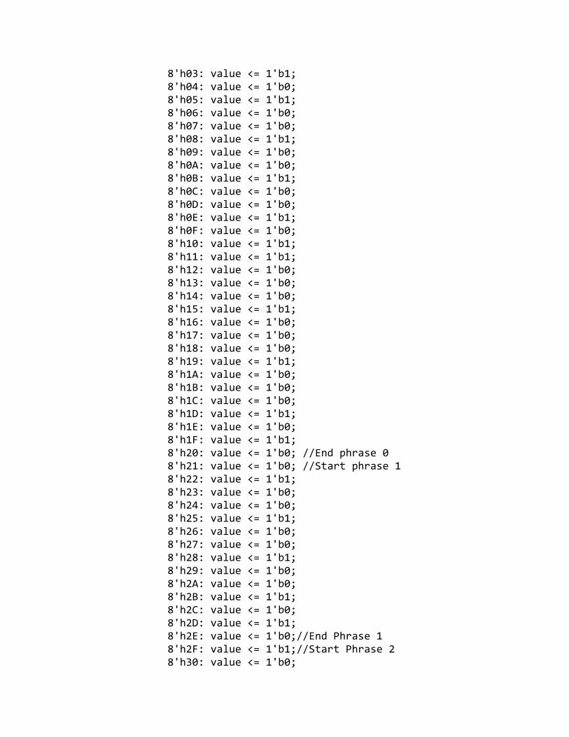
8'h03: value <= 1'b1; 8'h04: value <= 1'b0; 8'h05: value <= 1'b1; 8'h06: value <= 1'b0; 8'h07: value <= 1'b0; 8'h08: value <= 1'b1; 8'h09: value <= 1'b0; 8'h0A: value <= 1'b0; 8'h0B: value <= 1'b1; 8'h0C: value <= 1'b0; 8'h0D: value <= 1'b0; 8'h0E: value <= 1'b1; 8'h0F: value <= 1'b0; 8'h10: value <= 1'b1; 8'h11: value <= 1'b1; 8'h12: value <= 1'b0; 8'h13: value <= 1'b0; 8'h14: value <= 1'b0; 8'h15: value <= 1'b1; 8'h16: value <= 1'b0; 8'h17: value <= 1'b0; 8'h18: value <= 1'b0; 8'h19: value <= 1'b1; 8'h1A: value <= 1'b0; 8'h1B: value <= 1'b0; 8'h1C: value <= 1'b0; 8'h1D: value <= 1'b1; 8'h1E: value <= 1'b0; 8'h1F: value <= 1'b1; 8'h20: value <= 1'b0; //End phrase 0 8'h21: value <= 1'b0; //Start phrase 1 8'h22: value <= 1'b1; 8'h23: value <= 1'b0; 8'h24: value <= 1'b0; 8'h25: value <= 1'b1; 8'h26: value <= 1'b0; 8'h27: value <= 1'b0; 8'h28: value <= 1'b1; 8'h29: value <= 1'b0; 8'h2A: value <= 1'b0; 8'h2B: value <= 1'b1; 8'h2C: value <= 1'b0; 8'h2D: value <= 1'b1; 8'h2E: value <= 1'b0;//End Phrase 1 8'h2F: value <= 1'b1;//Start Phrase 2 8'h30: value <= 1'b0;
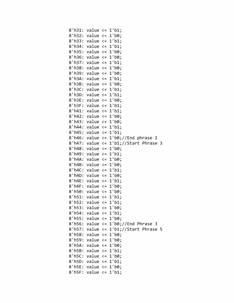
8'h31: value <= 1'b1; 8'h32: value <= 1'b0; 8'h33: value <= 1'b1; 8'h34: value <= 1'b1; 8'h35: value <= 1'b0; 8'h36: value <= 1'b0; 8'h37: value <= 1'b1; 8'h38: value <= 1'b0; 8'h39: value <= 1'b0; 8'h3A: value <= 1'b1; 8'h3B: value <= 1'b0; 8'h3C: value <= 1'b1; 8'h3D: value <= 1'b1; 8'h3E: value <= 1'b0; 8'h3F: value <= 1'b1; 8'h41: value <= 1'b1; 8'h42: value <= 1'b0; 8'h43: value <= 1'b0; 8'h44: value <= 1'b1; 8'h45: value <= 1'b1; 8'h46: value <= 1'b0;//End phrase 2 8'h47: value <= 1'b1;//Start Phrase 3 8'h48: value <= 1'b0; 8'h49: value <= 1'b1; 8'h4A: value <= 1'b0; 8'h4B: value <= 1'b0; 8'h4C: value <= 1'b1; 8'h4D: value <= 1'b0; 8'h4E: value <= 1'b1; 8'h4F: value <= 1'b0; 8'h50: value <= 1'b0; 8'h51: value <= 1'b1; 8'h52: value <= 1'b1; 8'h53: value <= 1'b0; 8'h54: value <= 1'b1; 8'h55: value <= 1'b0; 8'h56: value <= 1'b0;//End Phrase 3 8'h57: value <= 1'b1;//Start Phrase 5 8'h58: value <= 1'b0; 8'h59: value <= 1'b0; 8'h5A: value <= 1'b0; 8'h5B: value <= 1'b1; 8'h5C: value <= 1'b0; 8'h5D: value <= 1'b1; 8'h5E: value <= 1'b0; 8'h5F: value <= 1'b1;
8'h60: value <= 1'b0; 8'h61: value <= 1'b1; 8'h62: value <= 1'b0; 8'h63: value <= 1'b1; 8'h64: value <= 1'b0; 8'h65: value <= 1'b1; 8'h66: value <= 1'b0; 8'h67: value <= 1'b1; 8'h68: value <= 1'b0; 8'h69: value <= 1'b1; 8'h6A: value <= 1'b0;//End Phrase 5 8'h6B: value <= 1'b1;//Start Phrase 7 8'h6C: value <= 1'b0; 8'h6D: value <= 1'b0; 8'h6E: value <= 1'b1; 8'h6F: value <= 1'b0; 8'h70: value <= 1'b1; 8'h71: value <= 1'b1; 8'h72: value <= 1'b0; 8'h73: value <= 1'b1; 8'h74: value <= 1'b0; 8'h75: value <= 1'b1; 8'h76: value <= 1'b0; 8'h77: value <= 1'b0; 8'h78: value <= 1'b0; 8'h79: value <= 1'b1; 8'h7A: value <= 1'b0; 8'h7B: value <= 1'b1; 8'h7C: value <= 1'b0; 8'h7D: value <= 1'b1; 8'h7E: value <= 1'b0; 8'h7F: value <= 1'b1; 8'h80: value <= 1'b1; 8'h81: value <= 1'b0; 8'h82: value <= 1'b0; 8'h83: value <= 1'b1; 8'h84: value <= 1'b0; 8'h85: value <= 1'b1; 8'h86: value <= 1'b1; 8'h87: value <= 1'b0; 8'h88: value <= 1'b1; 8'h89: value <= 1'b0; 8'h8A: value <= 1'b0;// Phrase 7 end 8'h8B: value <= 1'b0;// Phrase 8 start 8'h8C: value <= 1'b1; 8'h8D: value <= 1'b0;
8'h8E: value <= 1'b1; 8'h8F: value <= 1'b0; 8'h90: value <= 1'b1; 8'h91: value <= 1'b0; 8'h92: value <= 1'b1; 8'h93: value <= 1'b0; 8'h94: value <= 1'b1; 8'h95: value <= 1'b0; 8'h96: value <= 1'b1; 8'h97: value <= 1'b0; 8'h98: value <= 1'b1; 8'h99: value <= 1'b0; 8'h9A: value <= 1'b1; 8'h9B: value <= 1'b0; 8'h9C: value <= 1'b1; 8'h9D: value <= 1'b0; 8'h9E: value <= 1'b1; 8'h9F: value <= 1'b0; 8'hA0: value <= 1'b0; 8'hA1: value <= 1'b1; 8'hA2: value <= 1'b0;// Phrase 8 end 8'hA3: value <= 1'b1;// Phrase 9 Start 8'hA4: value <= 1'b0; 8'hA5: value <= 1'b0; 8'hA6: value <= 1'b1; 8'hA7: value <= 1'b1; 8'hA8: value <= 1'b1; 8'hA9: value <= 1'b0; 8'hAA: value <= 1'b1; 8'hAB: value <= 1'b1; 8'hAC: value <= 1'b1; 8'hAD: value <= 1'b0; 8'hAE: value <= 1'b1; 8'hAF: value <= 1'b0; 8'hB0: value <= 1'b1; 8'hB1: value <= 1'b0; 8'hB2: value <= 1'b1; 8'hB3: value <= 1'b1; 8'hB4: value <= 1'b0; 8'hB5: value <= 1'b1; 8'hB6: value <= 1'b1; 8'hB7: value <= 1'b0; 8'hB8: value <= 1'b1; 8'hB9: value <= 1'b0;//Phrase 9 end 8'hBA: value <= 1'b0;//Start Phrase 10 8'hBB: value <= 1'b0;
8'hBC: value <= 1'b1; 8'hBD: value <= 1'b0; 8'hBE: value <= 1'b1; 8'hBF: value <= 1'b0; 8'hC0: value <= 1'b1; 8'hC1: value <= 1'b1; 8'hC2: value <= 1'b1; 8'hC3: value <= 1'b1; 8'hC4: value <= 1'b1; 8'hC5: value <= 1'b0; 8'hC6: value <= 1'b1; 8'hC7: value <= 1'b0; 8'hC8: value <= 1'b1; 8'hC9: value <= 1'b0; 8'hCA: value <= 1'b1; 8'hCB: value <= 1'b0; 8'hCC: value <= 1'b1; 8'hCD: value <= 1'b0;//End Phrase 10 8'hCE: value <= 1'b1;//Start Phrase 11 8'hCF: value <= 1'b0; 8'hD0: value <= 1'b0; 8'hD1: value <= 1'b1; 8'hD2: value <= 1'b0; 8'hD3: value <= 1'b1; 8'hD4: value <= 1'b1; 8'hD5: value <= 1'b0; 8'hD6: value <= 1'b1; 8'hD7: value <= 1'b0; 8'hD8: value <= 1'b1; 8'hD9: value <= 1'b1; 8'hDA: value <= 1'b0; 8'hDB: value <= 1'b1; 8'hDC: value <= 1'b0; 8'hDD: value <= 1'b1; 8'hDE: value <= 1'b1; 8'hDF: value <= 1'b1; 8'hE0: value <= 1'b1; 8'hE1: value <= 1'b1; 8'hE2: value <= 1'b1; 8'hE3: value <= 1'b0; 8'hE4: value <= 1'b1; 8'hE5: value <= 1'b0; 8'hE6: value <= 1'b1; 8'hE7: value <= 1'b0; 8'hE8: value <= 1'b1; 8'hE9: value <= 1'b0;
8'hEA: value <= 1'b0;//End Phrase 11 8'hEB: value <= 1'b0;//Start Phrase 12 8'hEC: value <= 1'b1; 8'hED: value <= 1'b0; 8'hEE: value <= 1'b1; 8'hEF: value <= 1'b0; 8'hF0: value <= 1'b0; 8'hF1: value <= 1'b1; 8'hF2: value <= 1'b0; 8'hF3: value <= 1'b1; 8'hF4: value <= 1'b1; 8'hF5: value <= 1'b01; 8'hF6: value <= 1'b01;//End Phrase 12 default: value <= 1'b0; endcase endmodule module flpr #(parameter bits =32) (input clk, reset, input [bits‐1:0] d, output reg [bits‐1:0] q); // Standard async reset flop always @(posedge clk, posedge reset) if (reset) begin q <=0; end else begin q <= d; end endmodule module counter #(parameter slow = 32) // Standard Counter with reset (input clk, reset, en, output reg [slow‐1:0] count); always @ (posedge clk, posedge reset) if (reset) count <= 8'b0; else if (en) count <= count +1; endmodule module flpre #(parameter bits =32) (input clk,reset, en, input [bits‐1:0] d,
output reg [bits‐1:0] q); // Standard async reset flop with en always @(posedge clk, posedge reset) if (reset) begin q <=0; end else if (en) begin q <= d; end endmodule module compareltoc #(parameter ctrl =32) (input clk, reset, input [ctrl‐1:0] sigin, output reg set); // This compares the last value seen with the current value to // detect change. wire [7:0] sighold0; //holds value of sigin for later compare flpr #(ctrl) siginflpr0 ( clk, reset, sigin, sighold0); always @ ( * ) begin if (sighold0 != sigin) set =1'b1; else set = 1'b0; end endmodule module mempnt #(parameter ctrl = 32) (input clk, reset, set, hold, input [ctrl‐1:0] setv, output reg [ctrl‐1:0] pnt); // Stores the pointer for a memory block increments if ! hold // Allows for the setting of the counter from an external source // Expects a bit to indicate hold // NOTE: Hold functionality tied to 0 because of issues always @ (posedge clk, posedge reset) if (reset) pnt <= 8'b00000000; else if (hold)
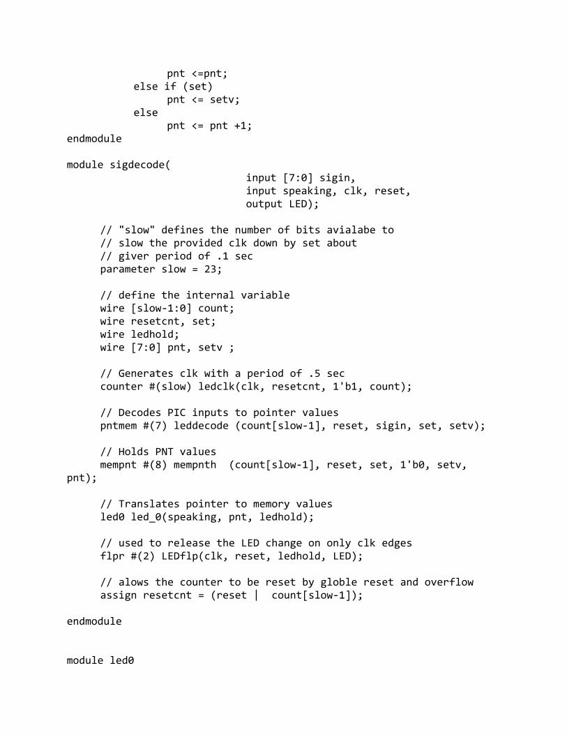
pnt <=pnt; else if (set) pnt <= setv; else pnt <= pnt +1; endmodule module sigdecode( input [7:0] sigin, input speaking, clk, reset, output LED); // "slow" defines the number of bits avialabe to // slow the provided clk down by set about // giver period of .1 sec parameter slow = 23; // define the internal variable wire [slow‐1:0] count; wire resetcnt, set; wire ledhold; wire [7:0] pnt, setv ; // Generates clk with a period of .5 sec counter #(slow) ledclk(clk, resetcnt, 1'b1, count); // Decodes PIC inputs to pointer values pntmem #(7) leddecode (count[slow‐1], reset, sigin, set, setv); // Holds PNT values mempnt #(8) mempnth (count[slow‐1], reset, set, 1'b0, setv, pnt); // Translates pointer to memory values led0 led_0(speaking, pnt, ledhold); // used to release the LED change on only clk edges flpr #(2) LEDflp(clk, reset, ledhold, LED); // alows the counter to be reset by globle reset and overflow assign resetcnt = (reset | count[slow‐1]); endmodule module led0
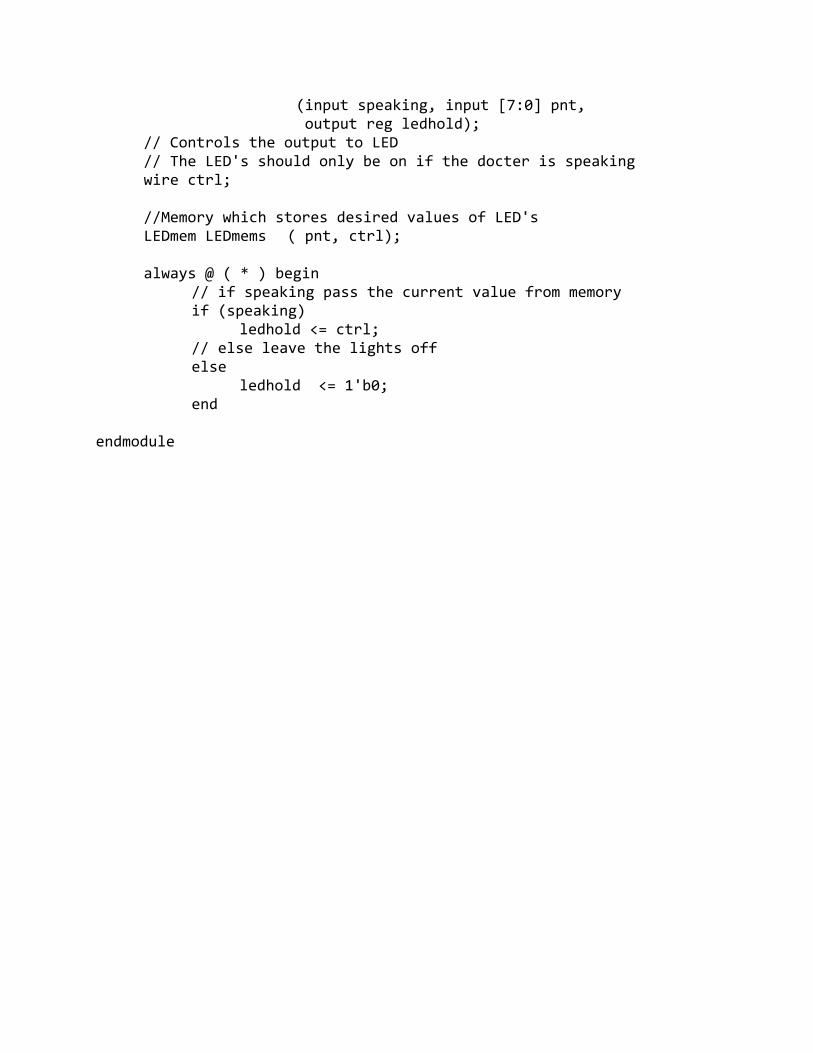
(input speaking, input [7:0] pnt, output reg ledhold); // Controls the output to LED // The LED's should only be on if the docter is speaking wire ctrl; //Memory which stores desired values of LED's LEDmem LEDmems ( pnt, ctrl); always @ ( * ) begin // if speaking pass the current value from memory if (speaking) ledhold <= ctrl; // else leave the lights off else ledhold <= 1'b0; end endmodule


![WELCOME [] Javed Consultant Psychiatrist, CWPT, UK.; ... Afzal Javed Consultant Psychiatrist, CWPT; President Elect World Psychiatric Association (WPA)](https://img.dokumen.tips/doc/110x75/5b03a9017f8b9a2d518c7d47/welcome-javed-consultant-psychiatrist-cwpt-uk-afzal-javed-consultant.jpg)