Embed Size (px)
Citation preview
Maryland Engineering Research Internship Teams (MERIT)
Robot Interaction Using Cricket, an Indoor Positioning System
Project by
Hosam Haggag University of Maryland, College Park
Golbarg Mehraei
Virginia Commonwealth University
Project Advisor
P.S. Krishnaprasad, Ph.D. University of Maryland, College Park
Graduate Assistants
Kevin Galloway University of Maryland, College Park
Zachary Kulis, M.S.
University of Maryland, College Park
In Collaboration With
Joshua Lioi Clemson University
© 2006

Robot Interaction Using Cricket, an Indoor Positioning System
Abstract .................................................................... 4
Introduction.............................................................. 4 AUTONOMOUS MOBILE ROBOTS ................................................................................................................ 4
Robot Mobility ...................................................................................................................................... 4 Autonomy .............................................................................................................................................. 4
ROBOT NAVIGATION .................................................................................................................................. 5 Definition .............................................................................................................................................. 5 Odometery............................................................................................................................................. 5
Cricket System ......................................................... 6 INVERSE CRICKET SYSTEM......................................................................................................................... 6
How it Works ........................................................................................................................................ 6 SETUP AND EXPERIMENTAL ENVIRONMENT ............................................................................................... 7
Calibrating Cricket Clients................................................................................................................... 7 STATIC TESTS USING ONE CLIENT ............................................................................................................. 8 DYNAMIC TESTS USING ONE CLIENT ......................................................................................................... 9 STATIC POSITIONING WITH TWO CLIENTS ................................................................................................ 11 CALCULATING ORIENTATION WITH TWO CLIENTS ................................................................................... 12
Orientation Test .................................................................................................................................. 12
MDLe, ME, and meesh ........................................ 14
MDLE ...................................................................................................................................................... 14 Definition ............................................................................................................................................ 14 Structure.............................................................................................................................................. 14 Example .............................................................................................................................................. 15
ME ........................................................................................................................................................... 16 MEESH........................................................................................................................................................ 17
CORBA................................................................... 17 DEFINITION AND USE ............................................................................................................................... 17 COMMUNICATION USING CORBA ........................................................................................................... 18
Example .............................................................................................................................................. 19
Tracking Algorithm............................................... 21 DEFINITION .............................................................................................................................................. 21 SETUP....................................................................................................................................................... 22 VARIABLE AND CONSTRAINT DEFINITIONS .............................................................................................. 22 TESTS VARYING CONSTRAINTS – ROBOT TO FIXED POINT ....................................................................... 23 ROBOT TO MOVING DESTINATION – CLASSICAL PURSUIT........................................................................ 26
Kalman Filters ....................................................... 29 APPLICATIONS OF THE KF ........................................................................................................................ 29 CONCEPT .................................................................................................................................................. 29
Beliefs ................................................................................................................................................. 29 Prediction-Correction......................................................................................................................... 30
KALMAN FILTER EQUATIONS ................................................................................................................... 30
Page 2 of 45

Robot Interaction Using Cricket, an Indoor Positioning System
System and Measurement Model......................................................................................................... 30 Prior State Estimate and Prior Error Covariance.............................................................................. 31 Posterior State Estimate and Covariance ........................................................................................... 31
Applications............................................................ 32
Appendix A............................................................. 33 CRICKET TESTS ON ROBOT GENGHIS........................................................................................................ 33 CRICKET TESTS ON ROBOT LOLA ............................................................................................................. 34 ROBOT TRACKING TESTS ......................................................................................................................... 37
References............................................................... 45
Page 3 of 45

Robot Interaction Using Cricket, an Indoor Positioning System
Abstract
In this project, a revised configuration of the Cricket indoor positioning system is used to enable coordinated robot interaction. The position of a Cricket client is determined by sending RF and ultrasonic signals to beacons on the ceiling of the lab and measuring the time taken for ultrasonic signals to be received. Robots determine their coordinates using this system and share this information to perform a designated task. The robots demonstrate good performance in rendezvous and pursuit tasks using instantaneous position values. To improve position estimates when noise is present in Cricket measurements, a Kalman filter is proposed.
Introduction
Autonomous Mobile Robots
Robot Mobility
The mobility of a robot can be described as the degree which a robot is able to freely move. This has become a significant technology in the field of robotics and intelligent controls. For instance, the Pioneer robots used in this project have great mobility. The wheels are able to rotate in any combination, resulting in forward, backward, and turning motions. The forward and rotational speed of these robots can be controlled; therefore, allowing the user to program the robot to turn quickly or very slowly. The mobility and control of these robots can be helpful in places where humans cannot explore. However, these robots do have their limits, such as being able to run over objects. The present objective today is to create robots that are fully mobile in order to perform certain tasks.
Autonomy
Autonomy of robots is defined as the extent of which a robot relies on prior known knowledge of the environment and an operator to complete its task. There are three classes of autonomy: non-, semi-, and fully autonomous robots [1].
Non-autonomous robots are completely steered by humans whereas semi-autonomous robots can either navigate independently or be steered by humans. In contrast, fully autonomous robots are steered by on-board programs able to accommodate uncertainties, sensor information and shifting goals. These robots are capable of intelligent motion and action without any external guidance. In dangerous environments,
Page 4 of 45

Robot Interaction Using Cricket, an Indoor Positioning System
it is best to have fully autonomous robots to complete tasks without any guidance. However, in some other cases it is best to give commands to the robot. In this project, the goal was to program the robots to be fully autonomous but a navigation system was needed to accomplish full autonomy.
Robot Navigation
Definition
For a mobile robot to drive to a location, it needs to navigate itself through its environment by determining its current position, the location of its target, and how it needs to get there safely. When path planning, the robot needs to consider obstacles that will interfere with its path. The recognition of obstacles can be determined through techniques such as infrared and sonar. Nevertheless, robots must have the capability to measure their current position in order to acquire a sense of where they are in the environment.
Odometery
A common technique used to determine the current position of the robot is odometery, whereby the robot calculates the distance it has traveled by the number of revolutions the wheel makes. However, the odometer readings may give inaccurate results due to wheel slippage and other noise that may affect the rotation of the robot. Furthermore, the robot alone cannot determine how accurate the readings from the odometer sensors are and because the current positions depend on previous readings, the error accumulates over time. Therefore, the robot needs other sensors to determine the error in the measurements. These sensors can use vision, compasses and active beacons to correct the error introduced by the odometery measurements [1]. For the purpose of precise position readings, the Cricket indoor positioning system, which will be further explained in this paper, was used.
Robot Interaction
In this project, the two robots communicated their positions to one another through a system called CORBA (see CORBA chapter). Using this knowledge, they were able to track and pursuit one another and meet at a single point without colliding. These simple tasks can be further altered to improve old methods. For instance, in Unmanned Air Vehicles (UAV), interaction among other UAVs is necessary for prevention of collisions and repetition in tasks. Compared to one UAV completing all tasks, several UAVs can perform many jobs such as monitoring of traffic in shorter time by interacting with one another. Thus, it is crucial to perfect robot interaction.
Problem
Page 5 of 45

Robot Interaction Using Cricket, an Indoor Positioning System
The purpose of this project is to use the Cricket system as a mean of robot localization and interaction. Robot localization is a problem in creating fully autonomous robots; however, by using the cricket system, localization of the robots is made possible. Interaction between robots is investigated by programming the robots to communicate their Cricket positions to one another and complete a task with the information.
Cricket System
Original Cricket System
The Cricket system enables devices to determine their position while indoors. Cricket units can be programmed as either beacons or clients (“Listener”). The beacons are mounted on the ceiling above the mobile robots. They are configured to send an ultrasonic pulse that is picked up by any listener below. With a unique ID, a beacon sends an RF signal pulse with its ID number, preceded by an ultrasonic pulse [2]. The timer on the client starts when it receives the RF signal and it stops when the ultrasonic pulse is received. Using the Time-of Flight information from different beacons and the temperature corrected speed of sound measurement; the client calculates its distance from the Beacons [2]. The position of the client can then be determined by correlating at least three Cricket measurements relative to the coordinate system of the beacons.
Inverse Cricket System
The Cricket system in the lab is inverted from the passive into an active network configuration. In contrast with the original Cricket configuration, the clients send up a RF pulse and ultrasonic signal which is simultaneously received by several beacons. This is more efficient because the time it takes to send an ultrasonic signal is too long; thus, when only one ultrasonic signal is sent per client rather than an ultrasonic signal sent by every beacon, the update speed of the system improves [2].
How it Works
The Inverse Cricket System defines Client 1 as the master client which sends out a synchronization pulse that keeps both the other clients and beacons running on the same clock. Each synchronization pulse is set to 1000ms [3]. This time is divided into time slice for each client. During its time slice, the client sends up a request which an RF and ultrasonic signal. The beacons within ultrasonic range receive the packet and calculate the distance between the client and each beacon. Each beacon then creates a packer that contains the client ID of the requesting unit and sends it through RF. When the client receives three packets from different beacons, it calculates its current position.
Page 6 of 45

Robot Interaction Using Cricket, an Indoor Positioning System
Furthermore, all the clients in RF range receive these packets and are able to calculate the position of every other client in radio range.
The some advantages to this Cricket configuration. For example, because the number of clients is less than the number of beacons, the amount of ultrasonic pulses is greatly reduced. There is a great advantage in using RF to send range measurements because these signals are transmitted more reliably; thus, RF signals cut down on error [3]. Furthermore, there is a less chance of a collision in the beacons transmissions because RF signals are far faster than ultrasonic signals.
Setup and Experimental Environment
Displayed in Figure 1, the Cricket setup in the lab consists of 10 ceiling mounted beacons with ID numbers from 1 to 10.
X
( 0 , 0 ) ( 0 , -182 )
( -120 , 0 )
Y
Figure 1: Cricket setup in the lab.
Each beacon unit can detect ultrasonic signals within 40 degree cone which translates to a 205cm radius. Any values received in the range of 40 to 45 degrees is not reliable because the range measurements become up to 10cm longer than they actually need to be. To prevent inaccurate range measurements, sets of three beacons are placed less than 203cm apart. This provides coverage to allow the clients on the robots to receive accurate values.
Calibrating Cricket Clients
When programming the Cricket units the accuracy of the ultrasonic ranging is tested. To calibrate the temperature corrected data, one Client is directly place underneath
Page 7 of 45

Robot Interaction Using Cricket, an Indoor Positioning System
Beacon 7 with their ultrasonic units facing each other. All other Beacons are shut off except for Beacon 7. The range from the ceiling sonar to the client board is 269.88 cm. The Client is directly connected to a computer. Using the hyper terminal the calibration constant is altered until the range received by the Client is close to the actual range. The default calibration constant is 40 microseconds. Each Client is calibrated in this manner.
Static Tests Using One Client
To test the consistency and accuracy of the Cricket system on each robot, the Clients on the robots are tested. The first test was a static experiment where measurements were taken at 30 second intervals during a single run. Between these intervals, the robot was moved forward 50 cm.
Static Test-1 Client
-50
0
50
100
150
200
250
300
-35 -30 -25 -20 -15 -10 -5 0
X (cm)
Y(cm
)
Figure 2: Static measurement test ran on robot Lola
Point Average X (cm) Standard Dev. X (cm) Average Y (cm) Standard Dev. Y (cm) 1 -29.94 0.40 3.01 1.932 -29.21 1.95 52.27 1.273 -30.03 1.49 98.94 0.854 -30.14 0.84 148.65 0.705 -31.13 1.05 200.06 1.006 -27.94 1.26 244.44 3.06
Figure 3: Table summarizing results of the static measurement
Page 8 of 45

Robot Interaction Using Cricket, an Indoor Positioning System
Static Test-1 Client
0
50
100
150
200
250
300
-100 -80 -60 -40 -20 0
X(cm)
Y(cm
)
Figure 4: Static measurement test ran on robot Genghis
Point Average X (cm) Standard Dev. X
(cm) Average Y (cm) Standard Dev. Y
(cm) 1 -32.77 0.73 3.93 0.722 -31.59 2.10 53.40 1.353 -30.70 2.13 101.09 1.284 -34.45 0.80 145.76 0.705 -33.34 0.92 197.73 0.916 -31.84 1.19 245.21 1.81
Figure 5: Table summarizing results of the static measurement
The experiment results show that both robots maintained a constant x-coordinate over a distance of two and half meters. The standard deviation of x and y for both robots is quite small resulting in less scattering of the points. However, it seems that the Client on the robot Genghis is a bit more accurate in stationary tests than the Client on robot Lola.
Dynamic Tests Using One Client
To determine the accuracy of the Cricket system while the robots are in motion, dynamic tests were performed. In the following two tests the position information was recorded while the robots moved in a straight line at 2.5cm/s and 10cm/s.
Page 9 of 45

Robot Interaction Using Cricket, an Indoor Positioning System
1 Client in motion -Line 2.5cm/s
-250
-200
-150
-100
-50
0
50
100
150
200
-100 -90 -80 -70 -60 -50 -40 -30 -20 -10 0
X(cm)
Y(cm
)
Figure 6: Position measurements taken while robot Lola was moving 2.5cm/s.
1 Client in Motion-Line 10cm/s
-300
-200
-100
0
100
200
300
400
-80 -70 -60 -50 -40 -30 -20 -10 0
X(cm)
Y(cm
)
Figure 7: Position measurements taken while robot Genghis was moving 10cm/s
The graphical representation of the data shows that the robots follow the measured path closely (linear line on the graph). However, it seems that the linearity of the data decreases with the speed: as the speed increases, the Clients on the robots are unable to pick up as many points compared to a slower speed. However in figure 7, the few points that are resulted follow the path accurately.
Page 10 of 45

Robot Interaction Using Cricket, an Indoor Positioning System
Static Positioning with Two Clients
Multi-client applications were tested by recording data from two Clients every second in a static position.
Two clients-Static
-35
-30
-25
-20
-15
-10
-5
0
5
10
-50 -45 -40 -35 -30 -25 -20 -15 -10 -5 0
X (cm)
Y (c
m)
Figure 8: Measured data taken from two Clients on robot Genghis
Client 1-Static
0123456789
-45 -40 -35 -30 -25 -20 -15 -10 -5 0
X(cm)
Y(cm
)
Figure 9: Client 1 Static Position Data
Page 11 of 45
Robot Interaction Using Cricket, an Indoor Positioning System
Client 2-Static
-35
-30
-25
-20
-15
-10
-5
0-45 -40 -35 -30 -25 -20 -15 -10 -5 0
X(cm)
Y(cm
)
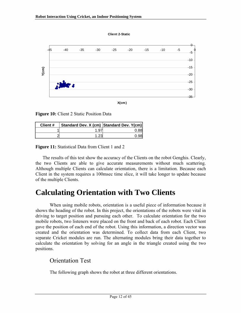
Figure 10: Client 2 Static Position Data
Client # Standard Dev. X (cm) Standard Dev. Y(cm)1 1.97 0.882 1.23 0.98
Figure 11: Statistical Data from Client 1 and 2
The results of this test show the accuracy of the Clients on the robot Genghis. Clearly, the two Clients are able to give accurate measurements without much scattering. Although multiple Clients can calculate orientation, there is a limitation. Because each Client in the system requires a 100msec time slice, it will take longer to update because of the multiple Clients.
Calculating Orientation with Two Clients
When using mobile robots, orientation is a useful piece of information because it shows the heading of the robot. In this project, the orientations of the robots were vital in driving to target position and pursuing each other. To calculate orientation for the two mobile robots, two listeners were placed on the front and back of each robot. Each Client gave the position of each end of the robot. Using this information, a direction vector was created and the orientation was determined. To collect data from each Client, two separate Cricket modules are run. The alternating modules bring their data together to calculate the orientation by solving for an angle in the triangle created using the two positions.
Orientation Test
The following graph shows the robot at three different orientations.
Page 12 of 45

Robot Interaction Using Cricket, an Indoor Positioning System
Orientation Data at Three Positions
-2.5
-2
-1.5
-1
-0.5
0
0.5
1
1.5
2
0 50 100 150 200 250
Measurements
Orie
ntat
ion
(rad
ians
)
Figure 11: Orientation measurements at static positions on robot Genghis Orientation: Average (cm) Standard Dev. (cm)
1 1.30 0.062 -0.06 0.063 -1.62 0.14
Figure 12: Statistical results of the test
This graph displays the orientation of robot Lola as it spun.
Orientation While spinning
-4
-3
-2
-1
0
1
2
3
4
0 50 100 150 200
Measurement
Orie
ntat
ion
(rad
ians
)
Figure 12: Orientation measurements while spinning on robot Lola
Page 13 of 45

Robot Interaction Using Cricket, an Indoor Positioning System
Although the Clients produce a small source of error due to noise, this method of
calculating orientation is sufficient compared relative positioning where error accumulates over time.
MDLe, ME, and meesh
MDLe Definition To be able to implement any control algorithm on a robot, a motion control
program must first be defined using motion control software. Motion Description Language, extended version (MDLe), is one such language designed to activate hardware device drivers in an object oriented manner using software. MDLe is an extremely portable and versatile language that may be used across different platforms that may even use different languages to control hardware. This concept of high-level programming allows MDLe to serve as the interface for a user, blinding the user to the underlying communication that is taking place between hardware and software. As a user, this can be extremely helpful, allowing the user to run the same control algorithm on different robots. [4]
To accomplish this high-level layered abstraction, the MDLe compiler requires knowledge of the architecture (ie. the type of robot) that it is running. This information is provided by the user. The compiler will then “point” MDLe commands to their corresponding pieces of code specified for that given platform. When that MDLe command is then called by that same platform, its specific code corresponding to that platform will be invoked. Thus, the same control algorithm written in MDLe may be used on different platforms by simply indicating which platform you are using.
Structure A control algorithm in MDLe is defined on several layers. The highest layer is
called a plan. A plan is composed of one or more atoms. Each atom is composed of quarks – one or more interrupt quarks, and an action quark. Each quark is an actual reference to software on the given platform. (ie. robot).
To execute a control algorithm, a plan is first loaded by MDLe. Since MDLe is running on a platform (ie. robot running Linux), it is managed by the platform’s scheduler, and is given only a designated time slice. Therefore, each step in the following will be executed within a given time slice. The first argument in a plan indicates how many times that plan is to be repeated. If it is desired to repeat the plan indefinitely, a
Page 14 of 45

Robot Interaction Using Cricket, an Indoor Positioning System
negative value is given. The second argument in a plan is one or more atoms. MDLe will then check against the interrupt quark; if it returns a 1, then the interrupt condition has not been satisfied, otherwise it will return a 0. If the interrupt condition has not been satisfied, MDLe will activate the action quark. The action quark will invoke code (in our case, C++ code) that will perform some action that will cause software to control hardware motion. If a desired action is completed within the scheduled time slice, then the action quark will return a 1 indicating its successful completion of that task. Otherwise, the action quark will return a 0, and control will be returned to it upon arrival of the next time slice. If the action quark successfully completes (ie. returns a 1) or the interrupt quark is satisfied (ie. returns a 0), then the next atom in the plan will be executed in the same manner.
Specific examples of interrupt quarks are shown below: (bumper): returns 0 when the robot’s bumper tape detects contact, 1 otherwise (wait n): returns 0 if n seconds have passed after an atom has begun to run, 1
otherwise (cricketStop c_type n): returns 0 if Cricket unit is within 5cm of value n
on the c_type coordinate axis (example: “CricketStop x 25” will return 0 if Cricket unit is between 20 and 30cm on the x-axis), 1 otherwise
A snippet of code for CricketStop interrupt quark is shown below, where
current is the current position (either x or y – determined by c_type), stop is the desired end position, and _M_Cricket is a reference to the Cricket unit:
switch(c_type) { case X: current = _M_Cricket->getAbsolutePosition().x; break; case Y: current = _M_Cricket->getAbsolutePosition().y; break; } if((current-stop)*(current-stop) < 25) return 1; else return 0;
Specific examples of action quarks are shown below: (go u w): sets robot speed to u (negative value will cause robot to reverse) and
angular velocity w (cricketGo x y): causes robot to drive to coordinate position defined by
(x,y) using tracking algorithm (see Tracking Algorithm chapter) (pursuit name): causes robot to pursue robot defined by name
Example
Page 15 of 45

Robot Interaction Using Cricket, an Indoor Positioning System
A complete MDLe script is shown below with explanation:
#!/bin/sh meesh $MEHOST << __EOF__ m.import cricket.me m.alloc /lib/cricket.me/Cricket /usr/cricket cd usr/cricket ./port_num {1} cd ../.. m.start cricket m.alloc /lib/cricket.me/Cricket /usr/cricket2 cd usr/cricket2 ./port_num {2} cd ../.. m.start cricket2 cd usr/mdle ./load_plan { testCricket = (Atom (bumper) (cricketGo -27.94 -83.82 )); } ./main { plans/testCricket } cd / __EOF__
Before any plan can be loaded into the robot, the ME shell (meesh) must first be
called on the given robot (see ME, meesh, and CORBA sections). We then must import the cricket module before we can instantiate any Cricket unit. After we have done so we must then allocate space in the ME for the first Cricket unit. We then run the meesh command ./port_num to define the port number for the first Cricket unit. We then run the first Cricket’s module. We then perform the same steps for the second Cricket unit. We then load a plan called testCricket which has only one atom. This atom is composed of a bumper interrupt quark, and with a cricketGo action quark. Running this atom by invoking the ./main command will cause the robot to move to coordinate (-27.94,-83.82) unless it hits a bumper on the way.
ME
To be able to translate the motion control program onto the physical structure of the robot, software that does this program-to-physical mapping is needed. Since the physical structure of one robot to another may differ, the software architecture must also be able to account for this while still applying the same motion control program. This is done using the Modular Engine (ME). In ME, each system component (actuators, sensors, motors, etc) are defined in modules and are loaded at runtime as needed [5]. Once several modules have been loaded, the ME will implement a scheduler to allow a
Page 16 of 45

Robot Interaction Using Cricket, an Indoor Positioning System
specific time slice to each of the activated modules in the system. One of these modules is the MDLe module, where plans will have been broken down into their respective atoms, which will in turn be broken down into their respective quarks. Once the module has reached the quark level, pointers corresponding to the interrupt and control functions are defined. As the corresponding quark is run, if the execution reaches its end or the interrupt is invoked, the next cycle given to the MDLe module by the scheduler will advance down the plan and change its interrupt and control pointers to the next atom.
When running ME, a user must define at least one module (in our project it is referred to as pioneer2pinky) which defines the machine-specific commands to the actuators, sensors, motors, etc.
meesh
Once ME has defined the corresponding pioneer2pinky module and any
other modules, a filesystem will have been defined on each robot. This filesystem will include all modules included in ME, all MDLe plans included by the user, and any robot-specific data such as actuator and sensor data. This filesystem can then be viewed by the Modular Engine Shell (meesh). An object reference to each robot’s meesh shell is accessible by referencing an ORB to it (defined in the next chapter). Once in meesh, one may invoke any plans or read any of the modules’ data. One may even go as much as modify actuator or sensor data directly, (ex. robot speed) which will then have an immediate effect on the robot.
CORBA
Definition and Use Common Object Request Broker Architecture (CORBA) is a language mainly
designed for communication between systems. These systems may differ in platform and also may differ in language. The heterogeneous nature of CORBA is what makes it such an appealing tool to use in system networks. There are several advantages to the heterogeneous nature of CORBA: the first is that technology is always changing and is doing so at a fast rate. Because of this technology change, networks will evolve with the evolving platforms instead of being constantly replaced with the newer technology. Therefore, a heterogeneous networking language is crucial in allowing the expansion of such networks without the need to replace all old technology. Another advantage of the heterogeneous nature of CORBA is that not one platform or language suits all applications. Some applications will perform better on some platforms or by using some languages, while other applications may perform better on a differing platform or by using a different language. Therefore, one networking tool is needed to consolidate all the
Page 17 of 45

Robot Interaction Using Cricket, an Indoor Positioning System
different languages used to one common shared network. A final advantage of using CORBA in a heterogeneous environment is that if one component of the network fails, it is unlikely to cause other non-dependable components to fail as well. This level of protection is guaranteed by the fact that the failed platform is independent of a different platform even though they are all on the same network. [6]
To perform across different platforms and across different languages, CORBA provides wrappers to specific function calls depending on the platform and language. These wrappers will allow portability into different languages, where the wrappers will end up looking much similar to header files but with much more expanded functionality. These wrapped objects may then be called from other programs or CORBA objects over the network. The wrapping from differing languages is allowed as CORBA is an interface definition language (IDL), where CORBA will map its wrapper to the desired language. Mappings exist for the following languages: Ada, C, C++, Lisp, Smalltalk, Java, Python, Perl, Visual Basic, and Tcl. For our project we are strictly using C++.
Communication Using CORBA Although a complete explanation of the CORBA language is beyond the scope of
this document, it is important to understand the basic building block of interfacing with CORBA. When using CORBA, all interface categories are linked by an Object Request Broker (ORB). A system using CORBA is set up such that there is a server and one or more clients. Objects are defined on the server (defined and compiled using the OMG IDL), where clients will request these objects using the corresponding ORB, and may invoke any of the procedures within this object. Client and server must then interface to each other using a CORBA ORB.
Image courtesy of Wikipedia [7]
Page 18 of 45

Robot Interaction Using Cricket, an Indoor Positioning System
CORBA is extremely critical in our application. Since there may be several robots that are designed on different platforms and coded in different languages, CORBA offers the heterogeneous platform required by such a setup. Similarly, in order for the robots to communicate with each other, they must be able to pass objects of data across the network to each other. Such objects will allow position, orientation, velocities, and other important data needed by robots in the network to be easily accessed from other robots.
Since CORBA IDL definitions have already been defined for our robot network,
time will not be spent describing the development of these definitions. Rather, the usage of these definitions pertaining to our application will be discussed. In our network, the server is hosted on a machine named Serret (serret.isr.umd.edu). Each client (ie robot) creates a reference to it’s ME on Serret, which is accessed and modified whenever any changes are made.
Example As mentioned in the previous chapter, any of the robot’s attributes, modules, or
plans may be read or even altered through its ME using meesh. Since each robot’s ME is hosted as an object on Serret, all one must do is obtain an ORB to the desired robot, then get a reference to the ME using that ORB. This is shown in the following code, which is implemented in our project: char *argv[3]; int argc; argv[0] = NULL; argv[1] = (char*)malloc(strlen("isllola")+1); strcpy(argv[1],"isllola"); argv[2] = NULL; argc = 2; CORBA::ORB_var orb = CORBA::ORB_init(argc,argv,"omniORB3"); CosNaming::NamingContext_var inc = resolve_init<CosNaming::NamingContext>(orb,"NameService"); CosNaming::Name n; n.length(3); n[0].id = CORBA::string_dup("isllola"); n[1].id = CORBA::string_dup("ME"); n[2].id = CORBA::string_dup("Runner"); RunnerRO_var runner = resolve_name<RunnerRO>(inc,n); CORBA::String_var pwd = CORBA::string_dup("/usr/cricket2/");
Page 19 of 45

Robot Interaction Using Cricket, an Indoor Positioning System
CORBA::String_var name = CORBA::string_dup("./abs_pos"); RunnerRO::argv_t argv1; CORBA::String_var output; CORBA::Short retval; runner->run_command(pwd, name, argv1, output, retval); This piece of code will allow us to run any command as if we were on meesh directly, and through this we are able to run plans, view or modify any system attributes. Each section of code will be explained in further detail below: char *argv[3]; int argc; argv[0] = NULL; argv[1] = (char*)malloc(strlen("isllola")+1); strcpy(argv[1],"isllola"); argv[2] = NULL; argc = 2; CORBA::ORB_var orb = CORBA::ORB_init(argc,argv,"omniORB3");
Before we can initialize an ORB, we must first define argc and argv. These two are necessary, since ORB_init assumes that an argc and argv have been provided from a command line (ex: “communicateRobot isllola” where isllola is the target robot desired to make communication with). By default, any command-line call will place the number of arguments on the command line in argc, and the actual strings of commands as an array in argv. For the purposes of ORB initialization, only argv[1], which is the name of the target robot to have communication with, is needed. Once we have these two variables defined, we can initialize the ORB using omniORB3 protocol (which is just a definition for the version of the ORB initialization). CosNaming::NamingContext_var inc = resolve_init<CosNaming::NamingContext>(orb,"NameService"); CosNaming::Name n; n.length(3); n[0].id = CORBA::string_dup("isllola"); n[1].id = CORBA::string_dup("ME"); n[2].id = CORBA::string_dup("Runner"); RunnerRO_var runner = resolve_name<RunnerRO>(inc,n); Once we have a defined ORB, we must then access the NameService on Serret (the server) to return a reference to the specified robot’s ME. The desired robot is defined in the n[0], the module is defined in n[1], and Runner (the meesh shell) is defined in
Page 20 of 45

Robot Interaction Using Cricket, an Indoor Positioning System
n[2]. We can then get a reference to meesh (as a Runner) by resolving the specific reference to ilsllola (our target robot) through the NameService. CORBA::String_var pwd = CORBA::string_dup("/usr/cricket2/"); CORBA::String_var name = CORBA::string_dup("./abs_pos"); RunnerRO::argv_t argv1; CORBA::String_var output; CORBA::Short retval; runner->run_command(pwd, name, argv1, output, retval); Once we have a reference to isllola’s meesh, we may now execute any command we need. To do this, we must first define the path to the desired command in pwd. Then we must define the actual command in name. Finally, we declare output and retval, where output will contain the output given after executing the command in name, and retval will contain a return value indicating successful execution of the command in name. In this specific example, we are simply reading the absolute position from cricket2 on Lola. Other commands may be executed which could read, or even modify, system attributes. For example, if someone wanted to know the current velocity of Lola, one would define pwd to have string “/usr/pinky/” and define name to have string “./velocity”. Although we have just shown one implementation of accessing a robot’s ME using CORBA, there are many other modules one may access. However, to be able to define an ORB for that module, an IDL must first be implemented. The example shown above where ME is accessed is an extremely useful one, since it applies to any robot running ME. However, ORBs to robot-specific modules (which have IDL definitions) may also be obtained, such as Pioneer2 Runner Object (Pioneer2RO), are only executable on a Pioneer robot. Since all modules are eventually handled by ME, having an ORB to ME would usually be the most flexible and easy way to access and modify robot attributes, plans, and other modules.
Tracking Algorithm
Definition
With the above groundwork in place, we may now begin to implement motion control algorithms. One key control concept is explored here, and that is of robot tracking. Using the Cricket system, we are able to pinpoint the location and orientation of the robot in the created coordinate space, which then allows us to determine how to move
Page 21 of 45

Robot Interaction Using Cricket, an Indoor Positioning System
it from its current position to any other position in the coordinate space. The control of this desired motion is hereby defined as the tracking algorithm.
Setup Let us first begin with tracking a fixed point in the coordinate space. Let us
assume that the robot is currently at position R(XR,YR) with orientation θ, and we define the destination position D(XD,YD). We will also define Φ which is the angle created when connecting a line between points R and D relative to the current value of θ.
Depending on the value of Φ, we can determine whether or not the Robot must
turn right or left; if Φ ranges between 0 to 180 degrees, we know that the robot must turn left, otherwise it must turn right. We will not consider the case when Φ is 180 degrees. However, if Φ is 0 degrees, then we know that the robot is facing the destination point and does not need to turn.
Using this knowledge we can then define the motion of the robot in two ways. The first is to simply rotate the robot until Φ is equal to 0 degrees, then drive forward. The second way is to drive forward at a constant speed, and rotate according to the value of Φ as it is driving forward. Both of these algorithms can work; however, in the interests of simulating a more natural and constant driving motion, the latter is used.
Variable and Constraint Definitions When implementing such an algorithm, there are several constraints that can be
set. The following are just a few constraints that will be discussed in further detail: forward speed, angular velocity, angle tolerance, and arrival tolerance.
R(XR,YR)
D(XD,YD) Y Φ
Front of Robot
θ X
Page 22 of 45

Robot Interaction Using Cricket, an Indoor Positioning System
Forward speed. Here we can define how the forward speed is set. We can either set it at a constant value, or we can make it variable depending on the distance from R to D. However, one must note that the faster the robot is moving forward, the less sampling the Cricket units (which provide the R position) will perform. It is critical to note that if the robot is moving too fast, it may overshoot the destination thinking that it has not arrived since it did not sample at that point, when in fact it did reach the destination. Examples of this will be shown later.
Angular velocity. This can determine how sharp the robot can turn. Like forward speed, this can be either a constant value or variable depending on the value of Φ. If the angular velocity is low, the robot will have much larger turning radius and thus less agile.
Angle tolerance. Previously, we mentioned that if Φ was equal to 0 degrees, then the robot will know that it does not need to turn anymore and can drive straight to its destination. However, due to the noise in Cricket measurements, even though the robot may physically have a Φ of value 0, it is highly unlikely that this will be the case. Therefore, one may define an angle tolerance such that if Φ is within this tolerance, it will assume that the destination is directly ahead and will not turn. The smaller this value is set, the more the robot will be accurate in its heading throughout the duration of the tracking. The larger this value is set the more smooth movement it will have, yet at the expense of many needed changes in turning as it approaches the destination.
Arrival tolerance. As the robot moves, it needs to determine whether it has arrived at the destination, namely whether R and D are equal. However, similar to the issue of angle tolerance where Cricket has noise measurements, it is also highly unlikely that R and D will both be identical. Therefore, arrival tolerance is defined to indicate how close R can be to D to consider that the robot has arrived at the destination. Picking a value for this tolerance depends on what the intended task of the robot is: if it is simply going to a fixed point in space and is not worried about colliding with anything near the destination point, then a small tolerance can be used. However, since the robot is large and the Cricket reports only a Cartesian coordinate, if the robot is to pursue another robot, the tolerance should be set to a larger number to prevent the robots from colliding thinking they have not met each other.
Tests Varying Constraints – Robot to Fixed Point Several tests have been performed while varying two of these four constraints:
forward speed, and angle tolerance. The other two constraints, angular velocity and arrival tolerance are fixed to 0.10 radians/sec and to within 5 cm in both the X and Y directions, respectively. These tests were then compared to theoretical simulations created in Matlab given the same constraints as those during each corresponding test. In each of these tests, the X and Y coordinates are in centimeters, the destination is denoted by a blue star, the red line indicates the theoretical path to the destination, and the green path shows the actual path reported by the Cricket units on the robot. Some tests will be shown here for discussion, while the rest of the tests are included in the appendix.
Page 23 of 45

Robot Interaction Using Cricket, an Indoor Positioning System
These three tests are shown with a forward speed of 0.05 meters/s. The angle
tolerances are shown to increase with the following: test 2 has angle tolerance of 5 degrees, test 9 has angle tolerance of 10 degrees, and test 7 has angle tolerance of 15 degrees. As was predicted, the smaller angle tolerance causes more adjusting, yet is more likely to be able to reach the destination on target. On the other hand, higher angle tolerances give smoother overall movement (as is seen clearly in test 7 with the highest angle tolerance), yet fail to adjust quick enough to head towards the destination point. Due to this, the robot determines that it has passed the destination and is left to try to drive in circle attempting to reach it. However, the large angle tolerance cause the robot to have a large turning radius since it can tolerate a large Φ value.
Page 24 of 45

Robot Interaction Using Cricket, an Indoor Positioning System
These tests both have the same angle tolerance of 5 degrees. However, as
mentioned before, test 2 has a forward speed of 0.05 meters/s while test 3 has a forward speed of 0.10 meters/s. Here we can clearly see that the faster robot movement completely drives over the destination. This is due to the fact that the Cricket units sample coordinate positions less often since the robot is moving faster. In this case, the Cricket units sampled before and after the destination outside of the 5 cm arrival tolerance, making the robot believe that it had never passed through the point. Since this tracking algorithm is static, problems like this can be avoided using a Kalman filter, which is explained in another chapter.
Furthermore, we can see the combination of a large forward speed with a large angle tolerance (with 15 degree angle tolerance) in test 8, where not only did the robot drive past the destination due to lack of enough samples, but it also was not able to turn itself in time due to the large angle tolerance. However, the large angle tolerance also shows us a much smoother tracking curve than that of test 3.
Page 25 of 45

Robot Interaction Using Cricket, an Indoor Positioning System
This test shows the ability of the robot to determine which direction to turn that
will require the least amount of turning. The robot is situated such that it is facing nearly directly away from the destination, with a slight turn so that the robot can determine that shorter path. The forward speed is set to a 0.05 meters/s minimum and the angle tolerance is set to a 5 degree minimum to achieve maximal results. Here, the robot proved to perform quite well.
Robot to Moving Destination – Classical Pursuit The previous discussion focused solely on the tracking of a robot to a fixed
destination. However, using the knowledge presented above using ME and CORBA, we can modify the destination from a fixed point to a moving point, namely another robot. Doing so will allow us to study a classical pursuit problem, where the pursuer drives towards the evader’s immediate position (ie. it does not incorporate any smart interception).
In our first test run for this we set up a robot named Genghis to pursue robot Lola.
Lola is controlled by an action quark keyboard, which allows us to drive Lola around using directional keys on a keyboard and at any speed we want.
Page 26 of 45

Robot Interaction Using Cricket, an Indoor Positioning System
-150
-100
-50
0
50
100
150
200
250
300
-160 -140 -120 -100 -80 -60 -40 -20 0
-200
-150
-100
-50
0
50
100
150
200
250
300
-300 -200 -100 0 100
Although the following graphs show no representation of elapsed time, the test
proved successful, and also shows the smooth movement of Genghis (shown in the first chart) as it is pursuing Lola (shown in the second chart).
In our second test run for interaction between the two robots, we make each robot
pursue each other. The robots were initially set up such that they are facing at approximately 45 degrees in opposite directions. Doing so will cause the robots to rendezvous at a certain point.
Page 27 of 45

Robot Interaction Using Cricket, an Indoor Positioning System
Like the other tests, both robots are run at a minimal forward speed of 0.05
meters/s and an angle tolerance of 5 degrees. We see that the experimental results are quite similar to the theoretical results. This test also shows the complete integration of ME, CORBA, and Cricket measurements.
Page 28 of 45

Robot Interaction Using Cricket, an Indoor Positioning System
Kalman Filters
The Kalman filter is defined as a recursive data processing algorithm that estimates the state of a noisy linear dynamic system. The filter takes into account all the noisy measurements from the different sensors and predicts a state q consisting of the x and y coordinates and the orientation of the robot.
To estimate the state, the filter needs to have access to the specifications of the system such as the range of the Cricket Beacons. These measurements are noisy and are linearly connected to the state. The Kalman filter uses knowledge of the system and sensor dynamics, probabilistic descriptions of the system and any other data that is about the initial state of the robot.
Currently, the paths of the robots are quite noisy and the robots tend to take longer paths than they need to. This is due to the noise seen at the sensors on the robots. The KF can reduce the noise which will yield more accurate position estimates of the robots. This, in turn, will also improve the paths the robots take to reach their destinations.
Applications of the KF
The Kalman filter is mainly used for control and prediction of dynamic systems. When KF controls the system, it is used as a state estimator. The KF is needed to measure every control variable in a complex system such as aircrafts and ships, because the risks would be too high if unfiltered, noisy data was used.
As a predictor, the Kalman filter estimates the future of the dynamic systems that are difficult to control. For example, Kalman filters can be used to predict the flow and trajectories of rivers during floods.
Concept
The Kalman filter works on a prediction-correction basis. It first makes a prediction based on the specifications of the system and then corrects the prediction by using the measurements of the system.
The filter estimates the true state of a system. It estimates the state and gives a measure of how certain it is of this estimation being the true state. However, estimation can be difficult because the state may not be directly observable and it can be subjected to noise. However, the KF still uses the measurements to make estimations.
Beliefs
Page 29 of 45
Robot Interaction Using Cricket, an Indoor Positioning System
The KF also estimates the probability of being in the state xk given available measurements. This is defined as the belief. This belief is split into the prior and posterior belief.
The prior belief is the conditional probability of being in a state xk given measurements z0, z1,…, zk-1. The posterior belief is the conditional probability of being in a state xk given measurements z0, z1,…, zk, so the difference is that the posterior belief includes the most recent measurement whereas the prior belief does not. To calculate these beliefs, the system model and the measurement model needs to be created. The system model and measurement model are explained in System and Measurement Model section below.
Prediction-Correction
Prediction. The Kalman filter calculates the belief by first computing the prior belief and then posterior belief. The prior belief can be the prediction of the state of the system after one step. The prediction uses the model system P(xk|xk-1) and the belief at what the state was before the last time step.
Correction. Because system noise, prediction error is possible; thus by computing the posterior belief, the correction of the state estimate results. After the KF calculates the prior belief, the measurement information provided by the measurement model P(zk|xk) is used to correct the predicted state. The measurement model describes how likely given a state xk a sensor reading results in measurement zk.
This is the main idea of the KF. It first predict the state and corrects the prediction using measurement information; thus, the prediction-correction system.
Kalman Filter Equations
To complete the process of the KF, several equations are required. To better understand the equation process, the KF equations will be used in a generic problem using robots. Note, the Kalman filter assumes that the robot system is linear.
System and Measurement Model
If a robot is represented by the state vector xk-1=[x,y,θk]T, the linear equation is represented in equation 1.1.
1k k k 1x Ax ω−= + − (1.1)
The system model describes how the true state evolves over time. In this equation, matrix A is an nxn that relates the state of the previous time step k-1 to the state at the current step k without taking into account the possible noise in the system. Matrix B is an
Page 30 of 45

Robot Interaction Using Cricket, an Indoor Positioning System
input gain matrix that relates control input vector to the current state. In the case of the robot, the control is constructed of the forward and rotational velocity. The component ωk-1 is the system noise in the state. The Kalman filter uses equation 1.1 to make a prediction.
To correct the state prediction when a measurement is available, a model measurement is needed.
z Hx vk k= + k
1k k
(1.2)
H is a mxn matrix that relates the current state xk to the measurement zk. H
models what the real measurement should be when there is no noise in the sensors given a state. The component vk is the measurement noise. In consideration of the robot problem, the measurements are the ranges given by the Cricket Beacons. [1]
Prior State Estimate and Prior Error Covariance
The prior state estimate is defined as the expected stave given all the measurements up to and including the last step. This can be expressed as in equation 1.3 below.
ˆ ˆx Ax=−
(1.3)
The prior covariance expressed in equation 1.4, determines the uncertainty in the state estimate being the true state.
1 1T
k k kP AP A Q− +− −= + (1.4 )
In the equation above, P+
k-1 expresses the uncertainty in the last posterior state estimate.
Posterior State Estimate and Covariance
The Kalman filter computes the posterior estimate when a measurement of the true state is given. The posterior state estimate is described as the equation below.
1( )ˆ ˆ ˆ( )
k k k k kT T
Kk k k
x x K z HxK P H HP H R
+ − −
− −
= + −= + −
(1.5)
Page 31 of 45
Robot Interaction Using Cricket, an Indoor Positioning System
Kk is the Kalman gain of the filter expressed above in terms of the prior covariance. The term (zk-Hxk
-) is the innovation of the filter that expresses how much a predicted measurement differs from the real measurement.
(k k ) kP I K H P+ −= − (1.6)
The posterior error covariance (1.6) determines the uncertainty of posterior state
estimate that the Kalman produces. The posterior state and covariance is the correction process of the KF. Overall, the KF filter uses the prior state equations to predict the current state and makes the correction using the posterior state equations.
Applications
The Cricket system can be used for many practical applications. This system can be combined with GPS to create a system where vehicles can determine their location indoors and outdoors. Cricket systems can be used in tunnels where GPS does not function. Furthermore, by using the Cricket system, fully autonomous mobile robots can explore areas that are difficult for humans to study.
This positioning system can also be used in the home. For instance, the Roomba vacuum robot does not have a sense of where it is going until it creates a map of the house; thus, it tends to bump into objects quite often. By using the Cricket system, the Roomba can determine at what location it is cleaning by using the position measurements from the Cricket beacons. By remembering the coordinates objects are located at, the Roomba can also avoid collisions. This would speed up the cleaning process greatly.
Communication among devices is essential. In this project, the two robots communicated their Cricket positions using CORBA, an enabled server/client platform. Using this knowledge of each other’s location, the two were able to complete simple tasks such as pursuing one another. This idea of completing tasks using communication among devices can be used for more important tasks. An example of this is in use with Unmanned Air Vehicles (UAV). These robots are able to complete tasks and prevent collisions by communicating with each other. Each UAV has knowledge of what the location of all the other UAVs are and what tasks the other UAVs have completed. By knowing this information, the UAVs can prevent repetition of an assignment and collision. Overall, communication between devices and localization using Cricket in a system can result in many fully autonomous mobile robots that have intelligent and useful controls.
Page 32 of 45

Robot Interaction Using Cricket, an Indoor Positioning System
Appendix A
This appendix includes all the graphs resulted from the different experiments.
Cricket Tests on Robot Genghis
1 Client Test-Line at 2.5cm/s
-300
-200
-100
0
100
200
300
400
-80 -70 -60 -50 -40 -30 -20 -10 0
X(cm)
Y(cm
)
Figure A1: Position measurements taken while robot Genghis was moving 2.5cm/s
Tracking a Circle at 2.5cm/s
-100
-80
-60
-40
-20
0
20
40
60
80
100
-350 -300 -250 -200 -150 -100 -50 0
X(cm)
Y(cm
)
Page 33 of 45

Robot Interaction Using Cricket, an Indoor Positioning System
Figure A2: Tracking a circle with a forwards speed of 2.5 cm/s and rotational speed of 0.033 rad/s
Two clients in motion (2.5cm/s)
-400
-300
-200
-100
0
100
200
-60 -50 -40 -30 -20 -10 0
X(cm)
Y(cm
)
Figure A3: Robot moving at the speed of 2.5cm/s with a two Client setup
Orientation while Spinnning
-4
-3
-2
-1
0
1
2
3
4
0 20 40 60 80 100 120
Measurement
Orie
ntat
ion
(rad
ians
)
Figure A4: Measured Orientation while robot spins at 2.5cm/s with a rotational speed of 0.033rad/s
Cricket Tests on Robot Lola
Page 34 of 45

Robot Interaction Using Cricket, an Indoor Positioning System
1 Client Test-Line 10cm/s
-300
-200
-100
0
100
200
300
400
-45 -40 -35 -30 -25 -20 -15 -10 -5 0
X (cm)
Y (c
m)
Figure A5: Position measurements taken while robot Lola was moving 10cm/s
Tracking a Circle at 2.5cm/s
-160
-140
-120
-100
-80
-60
-40
-20
0
20
40
60
-250 -200 -150 -100 -50 0
X(cm)
Y(cm
)
Figure A6: Tracking a circle with a forwards speed of 2.5 cm/s and rotational speed of 0.033 rad/s
Page 35 of 45

Robot Interaction Using Cricket, an Indoor Positioning System
Static Test-2 Clients
-25
-20
-15
-10
-5
0
5
10
-35 -30 -25 -20 -15 -10 -5 0
X(cm)
Y(cm
)
Figure A7: Static measurements with two Client setup
2 Clients in Motion
-250
-200
-150
-100
-50
0
50
100
150
200
-80 -70 -60 -50 -40 -30 -20 -10 0
X(cm)
Y(cm
)
Figure A8: Robot moving at the speed of 2.5cm/s with a two Client setup
Page 36 of 45

Robot Interaction Using Cricket, an Indoor Positioning System
Static Orientation
-1.5
-1
-0.5
0
0.5
1
1.5
2
2.5
0 20 40 60 80 100 120 140 160
Measurement
Orie
ntat
ion
(rad
ians
)
Figure A9: Static Orientation from a two Client setup
Robot Tracking Tests
Figures A10-A19 respectively is the results of a robot moving to a target position. The green line is the experiment results and the red line is the simulated path. Figures A20 and A21 are also the same test; however, the blue line is the experimental test and the red line is the theoretical path.
Specifications:
Forward Velocity: 0.05 m/s
Angular Velocity 0.1 rad/s
Degree Tolerance: 5 deg
Page 37 of 45

Robot Interaction Using Cricket, an Indoor Positioning System
-50 0 50-300
-200
-100
0
100
200
300
Robot Destination- Test 1
X Value
Y V
alue
-60 -40 -20 0-300
-200
-100
0
100
200
300Robot Destination- Test 2
X Value
Y V
alue
Figure A10 Figure A11
Page 38 of 45

Robot Interaction Using Cricket, an Indoor Positioning System
Specifications:
Forward Velocity: 0.1 m/s
Angular Velocity 0.1 rad/s
Degree Tolerance: 5 deg
-100 -50 0 50-300
-200
-100
0
100
200
300Robot Destination- Test 3
X Value
Y V
alue
-80 -60 -40 -20 0 20-300
-200
-100
0
100
200
300Robot Destination- Test 4
X Value
Y V
alue
Figure A12 Figure A13
Page 39 of 45

Robot Interaction Using Cricket, an Indoor Positioning System
-60 -40 -20 0 20-300
-200
-100
0
100
200
300
Robot Destination- Test 5
X Value
Y V
alue
-80 -60 -40 -20 0 20-300
-200
-100
0
100
200
300
Robot Destination- Test 6
X Value
Y V
alue
Figure A14 Figure A15
Specifications:
Forward Velocity: 0.05 m/s
Angular Velocity 0.1 rad/s
Degree Tolerance: 5 deg
Specifications:
Forward Velocity: 0.1 m/s
Angular Velocity 0.1 rad/s
Degree Tolerance: 5 deg
Page 40 of 45

Robot Interaction Using Cricket, an Indoor Positioning System
-100 -50 0 50-300
-200
-100
0
100
200
300
Robot Destination- Test 7
X Value
Y V
alue
-100 -50 0 50-300
-200
-100
0
100
200
300
400Robot Destination- Test 8
X Value
Y V
alue
Figure A16 Figure A17
Specifications:
Forward Velocity: 0.05 m/s
Angular Velocity 0.1 rad/s
Degree Tolerance: 15 deg
Specifications:
Forward Velocity: 0.1 m/s
Angular Velocity 0.1 rad/s
Degree Tolerance: 5 deg
Page 41 of 45

Robot Interaction Using Cricket, an Indoor Positioning System
-100 -50 0 50-300
-200
-100
0
100
200
300
Robot Destination- Test 9
X Value
Y V
alue
-80 -60 -40 -20 0 20-300
-200
-100
0
100
200
300Robot Destination- Test 10
X Value
Y V
alue
Figure A18 Figure A19
Specifications:
Forward Velocity: 0.05 m/s
Angular Velocity 0.1 rad/s
Degree Tolerance: 10 deg
Specifications:
Forward Velocity: 0.1 m/s
Angular Velocity 0.1 rad/s
Degree Tolerance: 10 deg
Page 42 of 45

Robot Interaction Using Cricket, an Indoor Positioning System
-100 -50 0-100
-80
-60
-40
-20
0
20
40
60
80
100
120
X Value
Y V
alue
Robot Destination Test 11
-50 0 50-300
-200
-100
0
100
200
300
Y V
alue
X Value
Robot Destination Test 12
Figure A20 Figure A21
Specifications:
Forward Velocity: 0.05 m/s
Angular Velocity 0.1 rad/s
Degree Tolerance: 5 deg
Specifications:
Forward Velocity: 0.05 m/s
Angular Velocity 0.1 rad/s
Degree Tolerance: 5 deg
Page 43 of 45

Robot Interaction Using Cricket, an Indoor Positioning System
Figure A22: Results of robot Lola and Genghis performing a rendezvous task under mutual pursuit law
Page 44 of 45

Robot Interaction Using Cricket, an Indoor Positioning System
References 1. Negenborn, R (2003). Robot Localization and Kalman Filters. Netherlands: Utrecht
University. 2. Kushleyev, A, & Young, T (2005). Cricket as a Positioning System for Control
Application.College Park,MD: University of Maryland. 3. Young, T (2005). Proof of Concept for Multiple Robot Communication using the
Cricket System. College Park, MD: University of Maryland. 4. Hristu-Varsakelis, D, Anderson, S, Zhang, F, Sodre, P, & Krishnaprasad, P.S.
(2003).A Motion Description Language for Hybrid System Programming. 5. Anderson, S.B., Handzel, A, Shah, Vinay, & Krishnaprasad, P.S. (2003). Robot
Phonotaxis with Dynamic Sound-source Localization. CDC. 6. Henning, M, & Vinoski, S (1999). Advanced CORBA Programming with C++.Upper
Saddle River, NJ: Addison-Wesley. 7. (2006). Wikipedia. Retrieved August 7, 2006, from Common Object Request Broker
Architecture Web site: http://en.wikipedia.org/wiki/CORBA
Page 45 of 45