Embed Size (px)
Citation preview
A111D3 im7Tfl
NATL INST OF STANDARDS & TECH R .C
A11 103109798/Robot crane technology •'Jnal report
QC100 .U5753 N0.1267 1989 V198 C.1 NIST-
NIST
PUBLICATIONS
1 States uepartment of Commercej| Institute of Standards and Technology
NIST Technical Note 1267
Robot Crane Technology
(Final Report)
Nicholas G. Dagalakis, James S. Albus, Kenneth R. Goodwin, James D. Lee,
Tsung-Ming Tsai, Hoosh Abrishamian, Roger Bostelman, and Charies Yancey
QC
100
.U5755
#1267
1989
C.2
rhe National Institute of Standards and Technology^ was established by an act of Congress on March 3,
1901. The Institute's overall goal is to strengthen and advance the Nation's science and technology and
facilitate their effective application for public benefit To this end, the Institute conducts research to assure interna-
tional competitiveness and leadership of U.S. industry, science and technology. NIST work involves development
and transfer of measurements, standards and related science and technology, in support of continually improving
U.S. productivity, product quality and reliability, innovation and imderlying science and engineering. The Institute's
technical work is performed by the National Measurement Laboratory, the National Engineering Laboratory, the
National Computer Systems Laboratory, and the Institute for Materials Science and Engineering.
The National Measurement Laboratory
Provides the national system of physical and chemical measurement;
coordinates the system with measurement systems of other nations
and furnishes essential services leading to accurate and uniform
physical and chemical measurement throughout the Nation's scientific
community, industry, and commerce; provides advisory and research
services to other Government agencies; conducts physical and chemical
research; develops, produces, and distributes Standard Reference
Materials; provides calibration services; and manages the National
Standard Reference Data System. The Laboratory consists of the
following centers:
The National Engineering Laboratory
Basic Standards^
Radiation ResearchChemical Physics
Analytical Chemistry
Provides technology and technical services to the public and private
sectors to address national needs and to solve national problems;
conducts research in engineering and applied science in support of these
efforts; builds and maintains competence in the necessary disciplines
required to carry out this research and technical service; develops engi-
neering data and measurement capabilities; provides engineering measure-
ment traceability services; develops test methods and proposes engi-
neering standards and code changes; develops and proposes newengineering practices; and develops and improves mechanisms to
transfer results of its research to the ultimate user. The Laboratory
consists of the following centers:
The National Computer Systems Laboratory
Computing and AppliedMathematics
Electronics and Electrical
Engineering^
Manufacturing EngineeringBuilding TechnologyFire Research
Chemical Engineering^
Conducts research and provides scientific and technical services to aid
Federal agencies in the selection, acquisition, application, and use of
computer technology to improve effectiveness and economy in Govern-ment operations in accordance with Public Law 89-306 (40 U.S.C. 759),
relevant Executive Orders, and other directives; carries out this mission
by managing the Federal Information Processing Standards Program,developing Federal ADP standards guidelines, and managing Federal
participation in ADP voluntary standardization activities; provides scien-
tific and technological advisory services and assistance to Federal
agencies; and provides the technical foundation for computer-related
policies of the Federal Government. The Laboratory consists of the
following divisions:
The Institute for Materials Science and Engineering
Information Systems
Engineering
Systems and Software
TechnologyComputer Security
Systems and NetworkArchitecture
Advanced Systems
Conducts research and provides measiurements, data, standards, refer-
ence materials, quantitative vmderstanding and other technical informa-
tion fundamental to the processing, structure, properties and perfor-
mance of materials; addresses the scientific basis for new advancedmaterials technologies; plans research around cross-cutting scientific
themes such as nondestructive evaluation and phase diagram develop-
ment; oversees Institute-wide technical programs in nuclear reactor
radiation research and nondestructive evaluation; and broadly dissem-
inates generic technical information resulting from its programs. TheInstitute consists of the following divisions:
Ceramics
Fracture and Deformation^PolymersMetallurgy
Reactor Radiation
'Hcadquartcre and Laboratories at Gaithersburg, MD, unless otherwise noted; mailing address
Gaithcrsburg, MD 20899.
'Some divisions within the center are located at Boulder, CO 80303.' Located at Boulder, CO, with some elements at Gaithersburg, MD.

ClC/oo
/TO. /^^7
NIST Technical Note 1267
Robot Crane Technology
(Final Report)
Nicholas G. Dagalakis, James S. A&xs. Kenneth R. Goodwin, James D. Lee,Tsuig-Ming Tsai. Hoosh Abrishamian, Roger BastsJman
Roixit SystsmB Dwision
and Charles Yancey
SfeuduBS DiwisnnOarter for BiAino Tadmology
>l I1^ id ^11 II* MM. t all III il INaDonai aion86nno LaooraKxy
National Insauto of Standards and TfldvwlogyGaflMrafaugL ifl> 20»9
Sponsored by:
Detanse Advanced Research Proiects Agency pARP/j140OWasonBoiJevanJAlineMti VA 22209-230B
JUiy1989
*^i«VEsa*
NOTE: As of 23 August 1988, the National Bueau dSlandards (NBS) became the Nadond insttubB of
SbndanJs and Technology ^<UST) wtwn Presidant
Reagan si^ied into law the Onv4xB Trade andComp^tlveness Act
nobert^ Mosbechar. Secretaiy
Natfonaf kKShJte of Standards and TectmdogyRbynond Q. Kanmar, AcfinQ Dinactor

National Institute of Standards U.S. Government Printing Office For sale by the Superintendent
and Technology Washington: 1989 of DocumentsTechnical Note 1267 U.S. Government Printing Office
Natl. Inst. Stand. Technol. Washington, DC 20402Tech. Note 1267
60 pages (July 1989)
CODEN: NTNOEF

TABLE OF CONTENTS
Executive Summary 1
1 . Introduction 5
1.1 Objective 5
1.2 Approach 5
1.3 Background 5
2 . The Proposed Crane Suspension Mechanism 7
3. NIST Work Prior to April 1, 1988 12
4. Report of the Progress in the Period From April 1 to November 31, 1988 14
4.1 Task I 14
4.2 Task II 15
4.3 Task III 2 5
4.4 Task IV 35
5 . Summary and Conclusions 4
1
6. Acknowledgments 44
7. References 45
Appendix I 49
111

Robot Crane Technology
Executive Summary
The objective of the Robot Crane Technology Program is to develop kinematically constrained,
dynamically stabilized, robot cranes capable of lifting, moving, and positioning heavy loads over
large volumes, capable of supporting fabrication tools and the inspection of large size and difficult
to reach structures.
Among the significant technologies pursued are:
* Achieve a better theoretical understanding of the properties of the proposed crane
suspension mechanism, such as stiffness, dynamics, and stability.
* Demonstrate the use of the robot crane mechanism for factory automation, such as
loading and unloading of machines, and moving heavy fixtures.
* Demonstrate the use of the robot crane mechanism for the fabrication and maintenance of
large and difficult to reach structures, such as airplanes, ships, and submarines.
* Demonstrate the use of the robot crane mechanism for the accurate and efficient
positioning of heavy payloads for the construction of airplanes, ships, submarines,
buildings, dams, and bridges.
The approach taken builds on previous work at the NIST Robot Systems Division which has
analyzed and measured the stiffness of a small model six-cable suspension system. This system is
a modified Stewart platform.
Under DARPA sponsorship, we have;
1. Extended this work to measure and optimize the stiffness of full-size models.
2. Actively damped oscillations in a small scale six-cable suspension platform.
3. Constructed an intermediate sized six-cable suspension platform for an industrial robot.
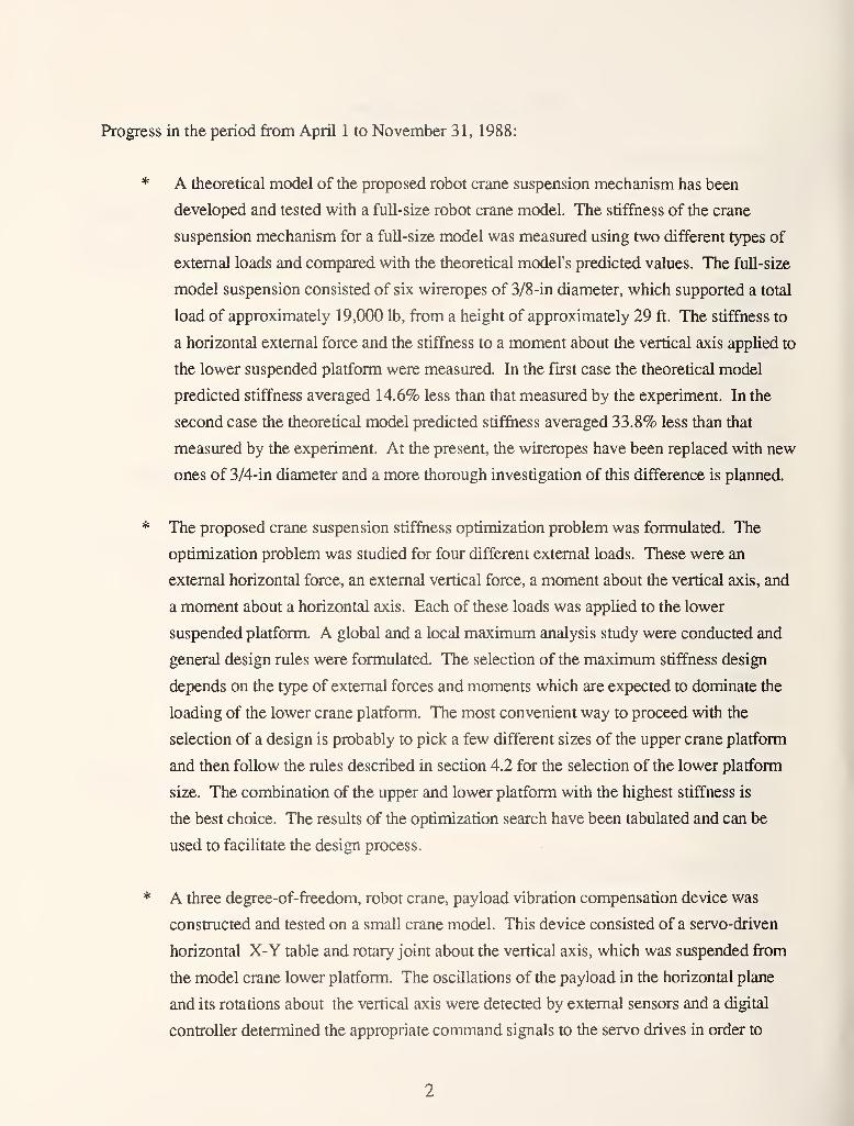
Progress in the period from April 1 to November 31, 1988:
* A theoretical model of the proposed robot crane suspension mechanism has been
developed and tested with a full-size robot crane model. The stiffness of the crane
suspension mechanism for a full-size model was measured using two different types of
extemal loads and compared with the theoretical model's predicted values. The full-size
model suspension consisted of six wireropes of 3/8-in diameter, which supported a total
load of approximately 19,000 lb, from a height of approximately 29 ft. The stiffness to
a horizontal extemal force and the stiffness to a moment about the vertical axis applied to
the lower suspended platform were measured. In the first case the theoretical model
predicted stiffness averaged 14.6% less than that measured by the experiment. In the
second case the theoretical model predicted stiffness averaged 33.8% less than that
measured by the experiment. At the present, the wireropes have been replaced with new
ones of 3/4-in diameter and a more thorough investigation of this difference is planned.
* The proposed crane suspension stiffness optimization problem was formulated. The
optimization problem was studied for four different extemal loads. These were an
extemal horizontal force, an extemal vertical force, a moment about the vertical axis, and
a moment about a horizontal axis. Each of these loads was applied to the lower
suspended platform. A global and a local maximum analysis study were conducted and
general design rules were formulated. The selection of the maximum stiffness design
depends on the type of extemal forces and moments which are expected to dominate the
loading of the lower crane platform. The most convenient way to proceed with the
selection of a design is probably to pick a few different sizes of the upper crane platform
and then follow the mles described in section 4.2 for the selection of the lower platform
size. The combination of the upper and lower platform with the highest stiffness is
the best choice. The results of the optimization search have been tabulated and can be
used to facilitate the design process.
* A three degree-of-freedom, robot crane, payload vibration compensation device was
constmcted and tested on a small crane model. This device consisted of a servo-driven
horizontal X-Y table and rotary joint about the vertical axis, which was suspended from
the model crane lower platform. The oscillations of the payload in the horizontal plane
and its rotations about the vertical axis were detected by extemal sensors and a digital
controller determined the appropriate command signals to the servo drives in order to
compensate them. A simple proportional gain digital controller algorithm was used for
this stage of the investigation. The gains were selected experimentally to minimize the
number and amplitude of the oscillations of the payload in the corresponding direction.
The payload response to force disturbances along the horizontal plane showed a
significant improvement when the vibration compensation control was on. The payload
response to moment disturbances about the vertical axis did not show any noticeable
improvement when the vibration compensation control was on.
* An intermediate-size model robot crane was constructed for factory automation
applications. Its upper platform was an equilateral triangle with a side length of 6 ft.
Based on the stiffness optimization study, the lower platform was selected to be one-half
the size of the upper platform. A PUMA-5601 robot arm was suspended from the lower
platform of this model. A robot tracking laser interferometer was used to monitor the
movements of the arm in three-dimensional space and software was written to process
and display the path tracking data. The robot arm tumed out to be quite stiff to any type
of external disturbances. Above a certain level, though, the wireropes would buckle,
making the arm feel very soft [ see fig. 12 of Dagalakis, N. G., et al., 1988]. This
breakaway feature could be very desirable for applications where safety requires that the
forces or moments appUed by the robot arm do not exceed certain limits.
Proposed future work:
* Theoretical study and measurement of the buckling characteristics of the robot crane
suspension mechanism.
* Design and test active damping and the micro-positioning control systems of an
intermediate scale crane platform.
* Add vision, touch, and force sensors and demonstrate the ability of a robot crane to load
and unload machine tools in a factory environment.
* Develop the proper sensors and grippers and demonstrate the ability of a robot crane to
pickup and deliver heavy fixtures in a factory environment.
1 Products named in this report are listed for purposes of information only. There is noimplied endoresement of any product or impUcation that they are the best available for the
purpose.

* Develop die prc^)er sensors and grippers and demcMistrate the ability of a robot crane to
pidciq) and deliver heavy fixtures in a factory environmem.
* Develc^ die proper sensors and grippers and dem<mstrate the abili^ of a robot crane to
provide latraial suppoat to do drilling and (kbumng of large and inaccessible sheet metal
structures.
* Retrofit a tower crane, d&yelop the premier sensors and grqjpers and demonstrate die
ability of a robot crane to pickup and deliver heavy paylc^ds of different shapes and
sizes for (X)nstructioQ wosk.
Robot Crane Technology
1 . Introduction
1.1 Objective
The objective of the Robot Crane Technology Program is to develop kinematically constrained,
dynamically stabilized, robot cranes capable of lifting, moving, and positioning heavy loads over
large volumes, capable of supporting fabrication tools and the inspection of large size difficult to
reach structures.
1.2 Approach
Our approach built on previous work at the NIST Robot Systems Division to analyze and measure
the stiffness of small model six-cable suspension systems. These systems are modified Stewart
platforms.
Extend this work to measure and optimize the stif&iess of full-size models, and actively dan^
osdlladons in tiie six-cable suspension platforms.
Design and construct a six-cable suspension platform and control system for an industrial robot so
the robot can move and work anywhere on or above a factory floor suspended by six cables from a
bridge crane.
1.3 Background
TTie last 10 years have seen a tremendous growth in the use of robots in the manufacturing industry
with more than 20,000 units installed in the United States, most of them in the automotive or
automotive-related industries [U.S. Department of Commerce, 1987]. Amidst this astounding
technological development, the application of robots in the large-scale fabrication, assembly and
heavy construction industry is virtually nonexistent in the United States. The reasons for delay are
probably because these are made-to-order industries, requiring precision in the construction of
components and blocks, requiring an enormous number of structural members and machines most
of which are heavy and bulky. In the case of heavy construction equipment, delays occur because
they operate in a more complex and unconstrained environment - that of the construction site.

Airplane manufacturing and shipbuilding, which are heavy assembly and construction industries,
being labor intensive, are becoming more expensive every year while robotic automation is
becoming less expensive and more capable every year.
In Japan, the Japanese Shipbuilding Society started a 5-year research and development plan of
"Modemization of Production Technology in Japan" in 1982 [Kubo, M., 1987]. The program is
sponsored by a consortium of seven major Japanese shipbuilders, and funded by the Japan
Foundation for Shipbuilding Advancement. As a result of this effort, prototypes of large size
gantry-type robots for welding, surface preparation, and painting of ship structures have been built
by Ishikawajima-Harima Heavy Industries Co. and are now being tested by Sumitomo Heavy
Industries, Ltd.
Currently, ordinary cranes are stable only in the vertical direction. The load is free to rotate in all
directions and sway in the horizontal plane under the slightest side pressure, similar to a pendulum.
Under these conditions it would be very difficult for the crane to support any robotic operations
due to the excessive compliance and low damping of its end-effector. Automatic crane antisway
control devices have been proposed and tested by several people [ Kogure, H. et al., 1978,
Carbon, L., 1976, Gercke, U.S. Patent No. 2,916,162]. Although these devices tend to
suppress the pendulum motions in the horizontal directions they fail to suppress any pitch, roll or
yaw rotations of the load. Other systems have been developed which try to solve the sway
problem by employing several wires and winches [ Noly, U.S. Patent No. 4,350,254]. These
systems add considerable complexity and cost to the load-handling system and have not found
practical application thusfar.
Conventionally designed robots have been scaled up and used as cranes, but they are largely
impractical for handling heavy loads. Due to the low payload-to-manipulator arm/weight ratio of
these robots, they have to be constructed of gigantic dimensions, occupy a large floor area, and
consume large amounts of power.
NIST has proposed a new crane design, which despite its simplicity, results in a very stiff load
platform which can be used as a robot base or end-effector for heavy loads.
2. The Proposed Crane Suspension Mechanism
Considering the requirements for a robot crane, which should provide superior stiffness to load
roll and sway, have a large work volume without occupying any significant floor space, and have a
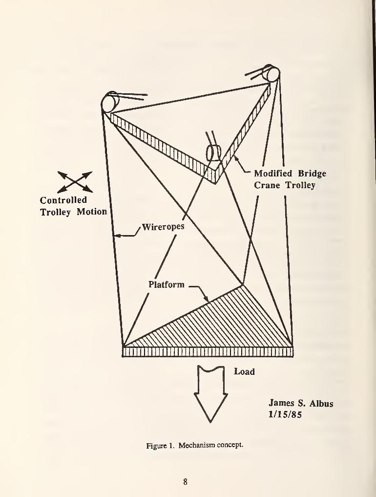
reasonable size, we have proposed the mechanism concept shown in figure 1 [ Albus, J. S.,
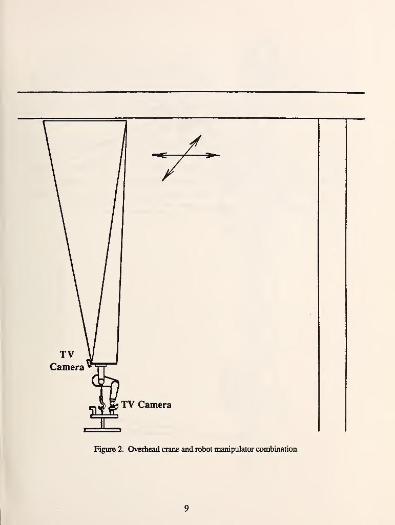
1987]. It consists of an equilateral triangular platform suspended by six wireropes, two at each
vertex of the triangle, from an overhead carriage. The carriage can be attached to either an
overhead (see fig. 2) or a boom crane, depending on the application. The carriage includes a
single winch onto which all six wireropes attach as shown in figure 3, and rope guides which
guide the six wireropes away from the winch in three pairs equidistantly spaced [ Albus, J. S., et
al., 1987]. If desired, it is possible to control the lengths of the individual wireropes with
actuators or brakes properly positioned either at the lower platform or the carriage.
The suspended platform behaves as if it is supported by an extendable single solid beam with its
elastic properties dependent on the weight of the load and the height of the crane for a given crane
geometry and wirerope type and size. This is a significant improvement in stiffness over a
conventional crane. It enables the load to be accurately positioned and provides a stable platform
which can be used to exert torques and side forces on objects being positioned. The suspended
platform can be used as a stabihzed base for the direct mounting of conventional manipulator arms
as shown in figure 2, or it can be used for the support of special substructures for specific crane
applications. These robot crane designs can also be used for factory automation where they offer
several advantages as compared with the usual current practice of having a manipulator dedicated to
serve each machine tool. These advantages are higher payload and fewer manipulators, which
hang from overhead rails and thus do not occupy valuable factory floor space.
The suspension mechanism of the proposed robot crane platform shown in figure 1 imitates the
behavior of a parallel Hnk manipulator arm. The arm mechanism is called parallel because the links
are positioned side by side, "approximately" parallel to each other and each link serves a role
"approximately" equal to that of its neighbor. This is different from the design of the more
common serial link manipulators built of a chain of links connected end-to-end in a serial manner.
Parallel link manipulators are, in general, known for the simplicity of their mechanical design, and
their high strength and stiffness-to-weight ratios, because their actuators bear no moment loads but
act in simple tension or compression. They are also known for their high force and moment
capacity, since their actuators all act in parallel. Such manipulators with solid adjustable length
beams in the place of the wireropes were first used for the design of tire test machines [Gough, V.
E. et al., 1957, 1962]; later they were used for the design of flight simulators [Stewart, D., 1965].
XControlled
Trolley Motion
Modified Bridge
Crane Trolley
Load
V James S. Albus
1/15/85
Figure 1. Mechanism concept.
8
7z
TV Camera
Figure 2. Overhead crane and robot manipulator combination.
9

c
45
9toCO
o
oVicuPuMPCO
JJJO
Uen
Hs
E
10
With the increasing interest in robotic arm manipulators, studies have been conducted for their use
as a mechanical wrist [Bennett, W. M., 1968], a compliant device [McCallion, H., at.al., 1979], a
force/moment or position sensor [Koliskor, A. S., 1982], a robot arm [Fichter, E. F., et al., 1980,
1984, 1987, Powell, I. L., 1982, Landsberger, S. E., et al., 1985, Sheridan, T. B., 1986,
Konstantinov, M. S., et al., 1985], and an industrial manipulator for assembly [Gadfly, 1983] and
for grinding[Multicraft, 1987].
The design discussed here takes advantage of the suspended crane load to maintain the wireropes
in tension and thus form six flexible wires which, with their elastic deformation, oppose any
displacement of the payload. The stiffness created by this elastic deformation is superimposed
onto the pendulum-effect-created-stiffness of ordinary cranes. Individual rope length control of the
position and orientation of the platfomi is also possible.
11
3. NIST Work Prior to April 1, 1988
A small model of the proposed robot crane suspension mechanism was constructed- The model
consisted of two aluminum triangular plates of equal side length 228.6 mm (9.0 in), see figure 1.
The lower platfonn was suspended by six steel wires. The height, which ranged finom 3 to 4.5 ft,
and the suspended weight W, which ranged from 100 to 350 lb, varied depending on the test
conditions. During testing, external loads (force or moment) of various amplitudes and
orientations were applied throu^ a multiaxis load-ceU. The resulting displacement in the direction
of load application was measured.
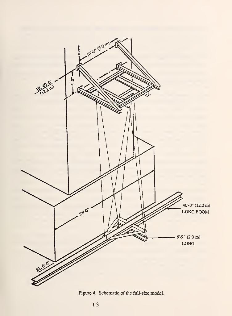
A full-size DKxiel of the crane suspension mechanism with a lateral translation end-load outfitting
subplatform structure, also was built, as shown in figure 4. It consists of a support frame
mounted on the concrete reaction wall of a seismic test facility and two I beams connected at a 90
degree angle. These two beams are suspended by six wires from the support frame at
approximately a 29-ft height and form the model of the lower platform and the subplatform
structure. Each wire is connected to these beams through a load-cell for monitoring its tension and
a tum-buckle for adjusting its length. The load, approximately 5,000 lb and the counter balance
weight, approximately 10,000 lb, are simulated by lead bricks placed in two baskets which hang
from the two ends of the long boom beam. This model was instrumented and used for the testing
reported in this work.
A computer model of the proposed robot crane stiffness based on the nonlinear equations of the
quasi-static motion of the lower platform was developed. Assuming small motions of the lower
robot crane platform, a linearized equations model of the stiffiiess was developed. The small robot
crane model test results were used to calculate the stif&iess to extemal loads and to compare with
the predicted values from the theoretical models. This work was described in [Dagalakis, N. G.,
et al., 1988].
12
40'-0" (12.2 m)
IX>NG BOOM
6'-9" (2.0 m)
LONG
Figure 4. Schematic of the full-size model.
13
4. Report of the Progress in the Period From April 1 to November 31, 1988
4.1 Task I
The objective of this task was to measure the stiffness of a full-size model of the proposed robot
crane suspension mechanism subjected to certain types of external loads and to compare the results
with those predicted by the theoretical model. The theoretical model was previously developed and
is described in [Dagalakis, N. G., et al., 1988].
A full-size model with a lateral translation end-load outfitting subplatform structure was completed
and used for the experimental work required for this task. Figure 4 shows a schematic drawing of
this model. The upper and lower platforms were constructed from steel I beams. The upper
platform was mounted on a specially designed steel frame which was then attached to the side of a
seismic reaction wall. The two platforms were constructed as equal equilateral triangles with a side
length of 6 ft. The vertical distance between the platforms was 28.6 ft. The lower platform was
suspended from the wireropes through six turn-buckles and six load-cells. The turn-buckles
allowed compensation for small differences of the wirerope lengths and made possible the leveling
of the lower platform. The load-cells were used to monitor the tensions of the wireropes. The
length of four of the wireropes was 25.8 ft, while the length of the other two was 24.8 ft. The
difference in lengths was due to the I beam construction of the upper platform. The total weight
suspended from the lower platform was 19,100 lb.
Due to the large magnitude of the external load forces and moments involved special heavy fixtures
had to be constructed to perform the stiffness measurement tests. A heavy optical bench was used
for the application of horizontal side forces and two large stanchions for the application of pure
moments. The translation and rotation of the lower platform was measured with a pair of
displacement transducers.
The wireropes used to suspend the lower platform were 3/8-in diameter, 6x19 classification, with
fiber core. In order to measure their Young's modulus of elasticity and stiffness it was decided to
obtain their stress strain curve. Three small specimens, each 3-ft in length were prepared and
tested on a materials testing machine. They were loaded and unloaded twice during each test. The
stiffness of the wirerope at 3,000 lb tension force of the second loading cycle was used to calculate
the modulus of elasticity. Its average value was found to be 13, 170, 208. Ib/in^.
14
The measurements which have been conducted so far were the stiffness for a horizontal force
applied to the center of gravity of the lower platform suspension plane and the stiffness for a
moment about the vertical axis applied to the same platform. Figure 5 shows the force versus
displacement plot from the first case superimposed to the theoretical model predicted plot. Figure 6
shows the moment versus angular displacement plot from the second case superimposed to the
theoretical model predicted plot.
In the first case the theoretical model predicted stiffness averaged 14.6% less than that measured by
the experiment. In the second case the theoretical model predicted stiffness averaged 33.8% less
than that measured by the experiment. At present, the wireropes have been replaced with new ones
of 3/4-in diameter and a more thorough investigation of this discrepancy is planned.
4.2 Task II
The objective of this task was the formulation and study of the proposed robot crane suspension
stiffness optimization problem and to determine whether there are design rules for the maximization
of the stiffness to external loading.
The optimization problem studied was the following. Determine the optimum combination of the
dimensions of the upper and lower platform of the proposed robot crane suspension mechanism,
which maximize its stiffness for practical values of the total suspended weight, crane height, and
diameter of the steel wireropes. In other words, assuming that a given payload has to be delivered
to a location of a given height, determine the robot crane design which will maximize its stiffness.
The stiffness matrix of the suspension mechanism for small displacements of the lower platform is
given by eqs (2) and (3) of [Unger, J., et al.,1988]. This matrix relates the three-dimensional
space forces and moments applied to the center of gravity of the lower platform suspension plane
(formed by the three suspension points) with the resulting translations and rotations.
The stiffness functions are as follows:
1. The stiffness K5 to a single external moment about the vertical axis, given by eqs (3) and (4)
of [Unger, J., et al.,1988].
2. The stiffness Kq to a single external moment about a horizontal axis, given by eq (6) of
[Unger, J., et al.,1988].
3
.
The stiffness K^ to a single external force about a horizontal axis, given by eq (5) of [Unger,
J., et al.,1988].
15

g 40.0000 "
•D- Test #1
•-Test #2
•O- Test #3
•- Theoretical model
0.0000
0.0000 0.1000 0.2000 0.3000 0.4000 0.5000
Displacement x [in]
Figure 5. Robot crane force-displacement test results.
16

350.00 •
300.00 •
5 250.00 •
•- Test#1
•o- Test#2
" Theoretical model
0.00 1 I I I I I
0.000 0.100 0.200 0.300 0.400
Angular Displacement [Degrees]
Figure 6. Robot crane moment-angular displacement test results.
17
4. The stiffness K3 to a single external force about the vertical axis, given by eqs (3) and (4) of
[Unger, J., et al.,1988].
The optimization properties of these functions were studied using optimization searching
techniques software programs and exhaustive search computer simulation and plotting programs.
The first type of programs used function gradient information to search for optima. The second
type of programs were used to gain a better understanding of the behavior of the functions and to
check the results of the first. Two different types of analyses were performed, the global
maximum analysis and the local maximum analysis. In the first case the relative maxima of the
previously mentioned stiffness functions were located for a wide range of payloads and heights.
In the second case the size of the upper platform was fixed and the size of the lower platform
which maximizes the same stiffness functions was determined (for more details refer to [Unger, J.,
et al.,1988]). The stiffness functions considered were linear with respect to the wirerope diameter,
and increasing diameter would increase the stiffness without reaching any maximum. The
wirerope diameter then was treated as an input parameter during the optimization search and not as
an optimization variable.
The results of the optimization search are as follows:
1 . The global analysis search of the stiffness K5 function did not locate any relative maximum in
the range of payloads (10,000 to 100,000 lb) and heights (10 to 100 ft) searched.
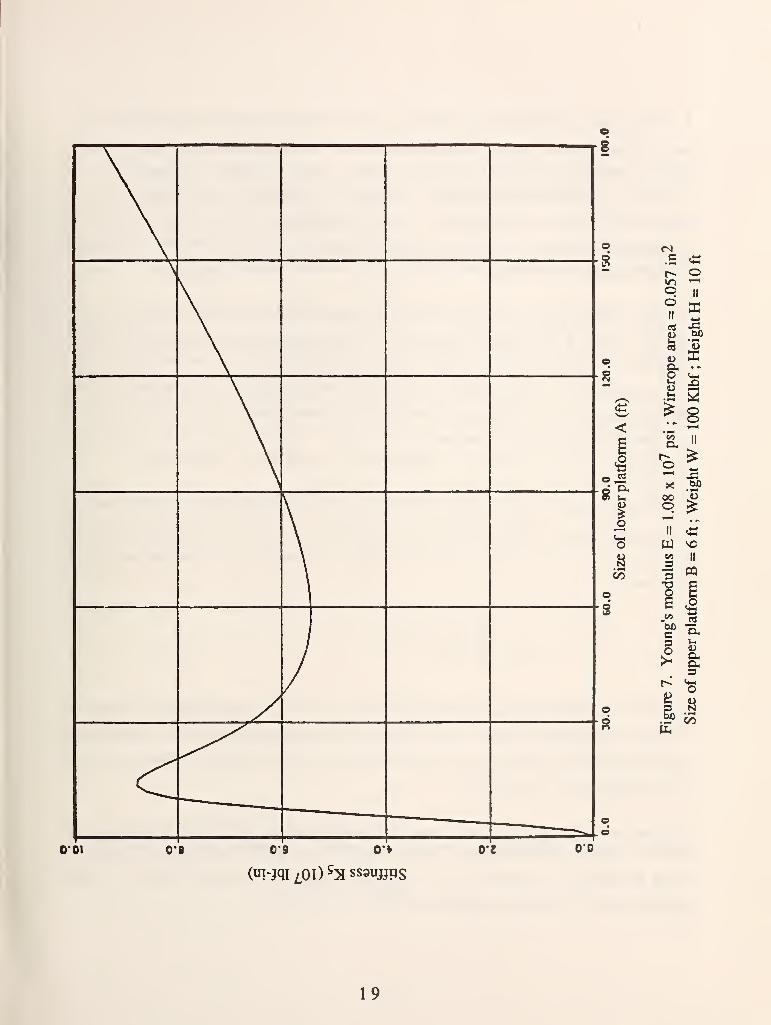
The local analysis search (for specific sizes of the upper platform) did identify local maxima and
minima. Figure 7 shows a typical plot of the stiffness function versus the size of the lower
platform, from the local analysis search. Where A and B are equal to one-half the side length of
the lower and upper equilateral triangle crane platforms respectively. The Young's modulus E and
area refer to the modulus of elasticity and effective cross sectional area of the selected wirerope.
An area of 0.057 in ^ corresponds to a wirerope diameter of 3/8 in. From this figure it can be seen
that the stiffness K5 is equal to zero when A is equal to zero. As A increases the stiffness
increases reaching first a local maximum and then a local minimum; beyond that the stiffness keeps
increasing as A increases. For practical applications where A cannot exceed 10 to 20 ft this plot
can be used to select A, which maximizes the suspension stiffness to a single external moment
about the vertical axis.
18
s
s
<
o
1>N00
O'Ol oe 0*9 O'V
(uT-jqi£0i)^:sss3uj}ps
0'{ 00
s
19
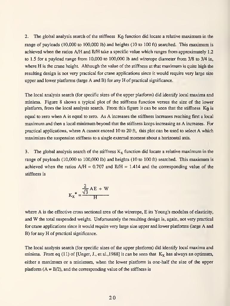
2. The global analysis search of the stiffness Kq function did locate a relative maximum in the
range of payloads (10,000 to 100,000 lb) and heights (10 to 100 ft) searched. This maximum is
achieved when the ratios A/H and B/H take a specific value which ranges from approximately 1.2
to 1.5 for a payload range from 10,000 to 100,000 lb and wirerope diameter from 3/8 to 3/4 in,
where H is the crane height. Although the value of the stiffness at that maximum is quite high the
resulting design is not very practical for crane applications since it would require very large size
upper and lower platforms (large A and B) for any H of practical significance.
The local analysis search (for specific sizes of the upper platform) did identify local maxima and
minima. Figure 8 shows a typical plot of the stiffness function versus the size of the lower
platform, from the local analysis search. From this figure it can be seen that the stiffness Kq is
equal to zero when A is equal to zero. As A increases the stiffness increases reaching first a local
maximum and then a local minimum beyond that the stiffness keeps increasing as A increases. For
practical applications, where A cannot exceed 10 to 20 ft, this plot can be used to select A which
maximizes the suspension stiffness to a single extemal moment about a horizontal axis.
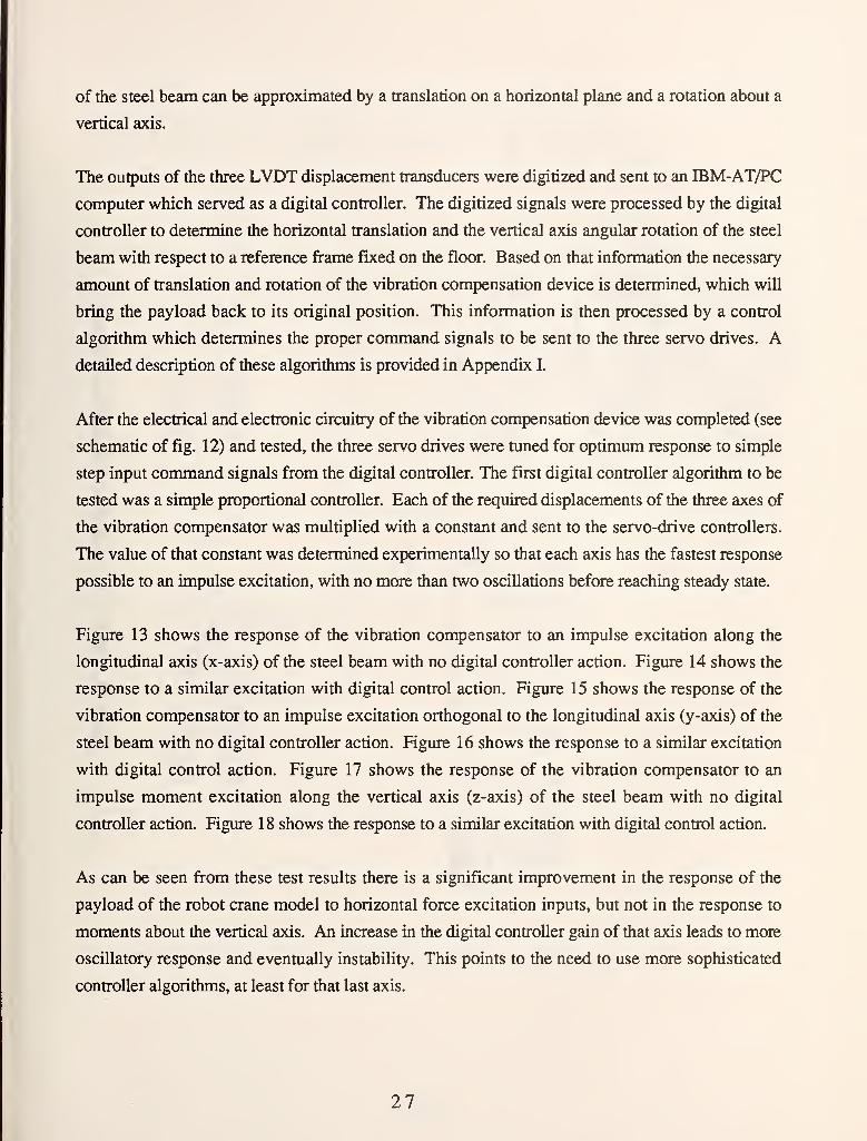
3. The global analysis search of the stiffness Kx function did locate a relative maximum in the
range of payloads (10,000 to 100,000 lb) and heights (10 to 100 ft) searched. This maximum is
achieved when the ratios A/H = 0.707 and B/H = 1.414 and the corresponding value of the
stiffness is
where A is the effective cross sectional area of the wirerope, E its Young's modulus of elasticity,
andW the total suspended weight. Unfortunately the resulting design is, again, not very practical
for crane applications since it would require very large size upper and lower platforms (large A and
B) for any H of practical significance.
The local analysis search (for specific sizes of the upper platform) did identify local maxima and
minima. From eq (1 1) of [Unger, J., et al.,1988] it can be seen that Kx has always an optimum,
either a maximum or a minimum, when the lower platform is one-half the size of the upper
platform (A = B/2), and the corresponding value of the stiffness is
20
o
NC/3
02 9'S 2V 8J
("I-jqi £01) ^X ss3uyp5
VI 0*0
c
mooII
a
oII
X
On • "^
>.8C/3
o,
oX
oII «W ^
3 "^
O Ce ^
I ^
o6 **s
N.5- W
21
^ * 3AEB2 W
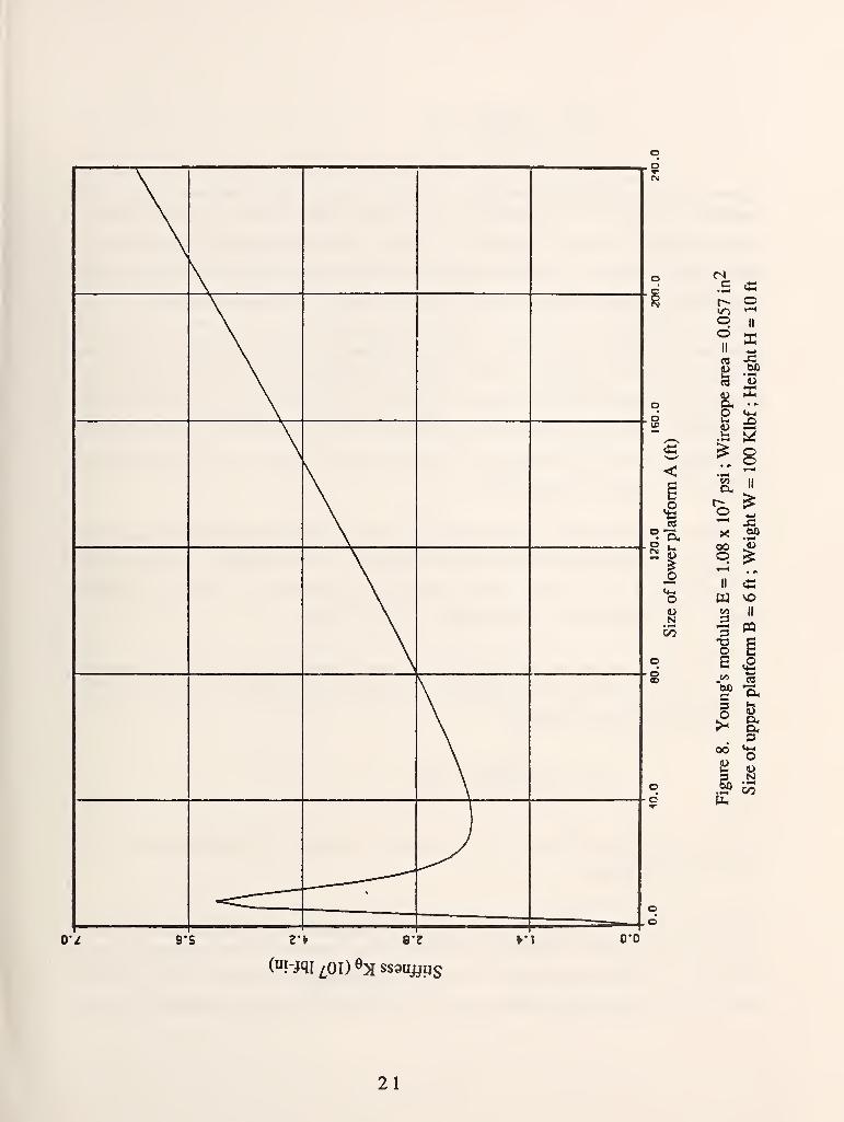
Figure 9 shows a typical plot of the stiffness function versus the size of the lower platform, from
the local analysis search. From this figure it can be seen that the stiffness Kx reaches a maximum
when A is equal to zero. This corresponds to the case of an inverted pyramid suspended from its
base, which is very stiff to a single external force about a horizontal axis applied at its peak.
Unfortunately this is not a realistic design because the stiffness to any moment applied to the lower
platform would be zero as we saw previously. The maximum at A = on figure 9 follows a local
minimum and a local maximum at A = B/2. By varying the values of the payload, height and
wirerope diameter it is possible to result in the movement of the maximum towards higher values
ofA and its replacement by a minimum at A = B/2 as can be seen from figures 2 and 3 of [Unger,
J., et al.,1988]. To select the proper A then the value of Kx for the smallest possible A will have
to be compared with that of the local maximum and the largest of the two used for the selection of
A, which will be used for the actual design.
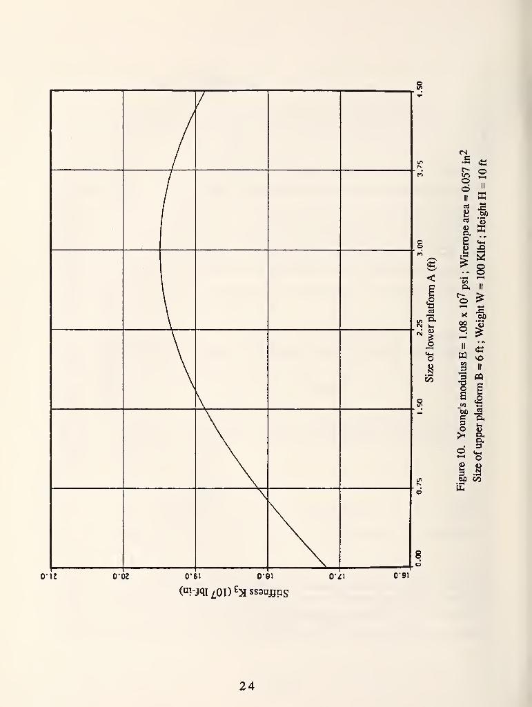
4. The global analysis search of the stiffness K3 function did locate a relative maximum in the
range of payloads (10,000 to 100,000 lb) and heights (10 to 100 ft) searched. This maximum is
achieved when A = B = and it is not a realistic design because the stiffness to any moment
applied to the lower platform would be zero as we saw previously.
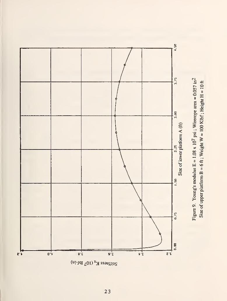
The local analysis search (for specific sizes of the upper platform) did identify a local maximum
when the lower platform is one-half the size of the upper platform (A = B/2), and the
corresponding value of the stiffness is
^ * 6AEH2 WKb
=(H2+B:i)3/2 + H-
Figure 10 shows a typical plot of the stiffness function versus the size of the lower platform, from
the local analysis search.
From the optimization results discussed so far it is obvious that the selection of the maximum
stiffness design depends on the type of external forces and moments which are expected to
dominate the loading of the lower crane platform during actual operation. To help with the
selection of the proper design we have tabulated the results of the computer optimization searches
22
(I
9 ^=
§IT) jS
o
NC?5
S
r> O-V
("i-jqr/,oi)'':sss9u^ps
V£ ZE
«nodII
iuo
II
'53
1^^.8
ooO §
S2 II
I «o c
c3O
On
3
-2
uOha.3
?^
S^ CO
23
/i
/
1
1
1
I
^
\\
\
"I1—4
ouNI/)
8
0-12 0"02 0*61 O'Bl o-^i 0-91
<sc «o
oIIo
II ffi
rt
2^ W)• wmw uK
p. II
»-H 4-1
X {JO
s III ^
GO
II
CQ
•^ex
d 5^ o
bJQ CO
PL,
24
for three different wirerope diameters (3/8, 9/16, 3/4 in), for a range of payloads from 10,000 to
100,000 lb in increments of 10,000 lb and heights from 10 to 100 ft in increments of 10 ft
4.3 Task III
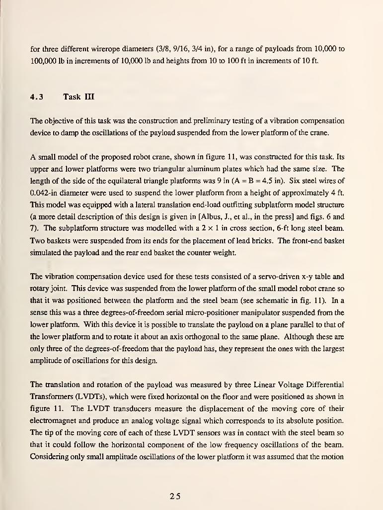
The objective of this task was the construction and preliminary testing of a vibration compensation
device to damp the oscillations of the payload suspended from the lower platform of the crane.
A small model of the proposed robot crane, shown in figure 11, was constructed for this task. Its
upper and lower platforms were two triangular aluminum plates which had the same size. The
length of the side of the equilateral triangle platforms was 9 in (A = B = 4.5 in). Six steel wires of
0.042-in diameter were used to suspend the lower platform from a height of approximately 4 ft.
This model was equipped with a lateral translation end-load outfitting subplatform model structure
(a more detail description of this design is given in [Albus, J., et al., in the press] and figs. 6 and
7). The subplatform structure was modelled with a 2 x 1 in cross section, 6-ft long steel beam.
Two baskets were suspended from its ends for the placement of lead bricks. The front-end basket
simulated the payload and the rear end basket the counter weight.
The vibration compensation device used for these tests consisted of a servo-driven x-y table and
rotary joint. This device was suspended from the lower platform of the small model robot crane so
that it was positioned between the platform and the steel beam (see schematic in fig. 11). In a
sense this was a three degrees-of-freedom serial micro-positioner manipulator suspended from the
lower platform. With this device it is possible to translate the payload on a plane parallel to that of
the lower platform and to rotate it about an axis orthogonal to the same plane. Although these are
only three of the degrees-of-freedom that the payload has, they represent the ones with the largest
amplitude of oscillations for this design.
The translation and rotation of the payload was measured by three Linear Voltage Differential
Transformers (LVDTs), which were fixed horizontal on the floor and were positioned as shown in
figure 11. The LVDT transducers measure the displacement of the moving core of their
electromagnet and produce an analog voltage signal which corresponds to its absolute position.
The tip of the moving core of each of these LVDT sensors was in contact with the steel beam so
that it could follow the horizontal component of the low fr-equency oscillations of the beam.
Considering only small amplitude oscillations of the lower platform it was assumed that the motion
25
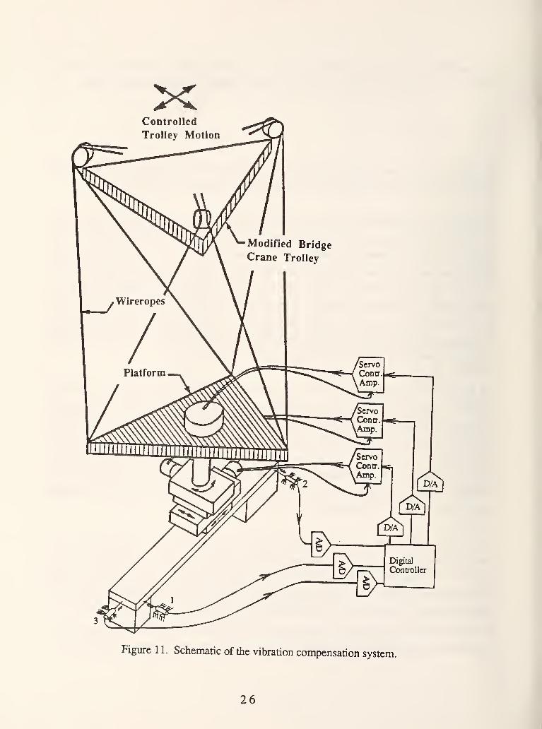
Figure 1 1. Schematic of the vibration compensation system.
26
of the steel beam can be approximated by a translation on a horizontal plane and a rotation about a
vertical axis.
The outputs of the three LVDT displacement transducers were digitized and sent to an IBM-AT/PC
computer which served as a digital controller. The digitized signals were processed by the digital
controller to determine the horizontal translation and the vertical axis angular rotation of the steel
beam with respect to a reference frame fixed on the floor. Based on that information the necessary
amount of translation and rotation of the vibration compensation device is determined, which will
bring the payload back to its original position. This information is then processed by a control
algorithm which determines the proper command signals to be sent to the three servo drives. Adetailed description of these algorithms is provided in Appendix I.
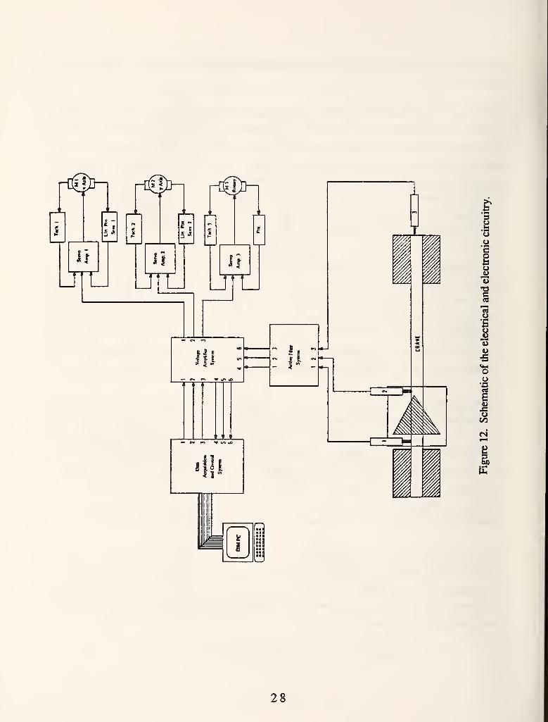
After the electrical and electronic circuitry of the vibration compensation device was completed (see
schematic of fig. 12) and tested, the three servo drives were tuned for optimum response to simple
step input command signals from the digital controller. The first digital controller algorithm to be
tested was a simple proportional controller. Each of the required displacements of the three axes of
the vibration compensator was multiplied with a constant and sent to the servo-drive controllers.
The value of that constant was determined experimentally so that each axis has the fastest response
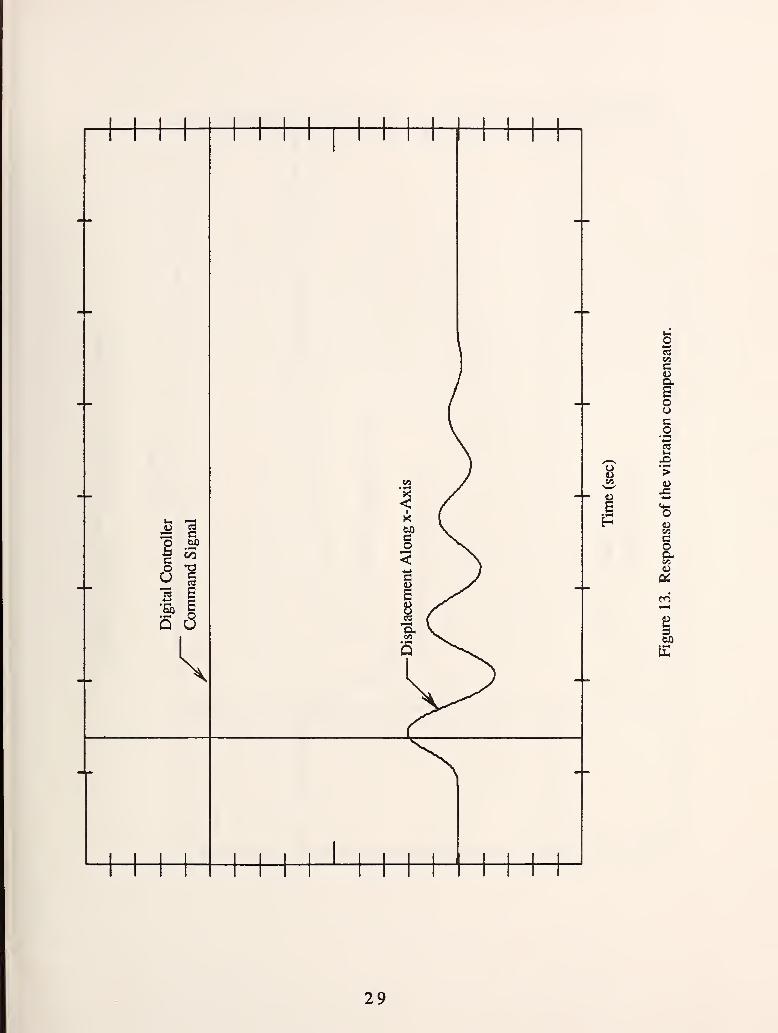
possible to an impulse excitation, with no more than two oscillations before reaching steady state.
Figure 13 shows the response of the vibration compensator to an impulse excitation along the
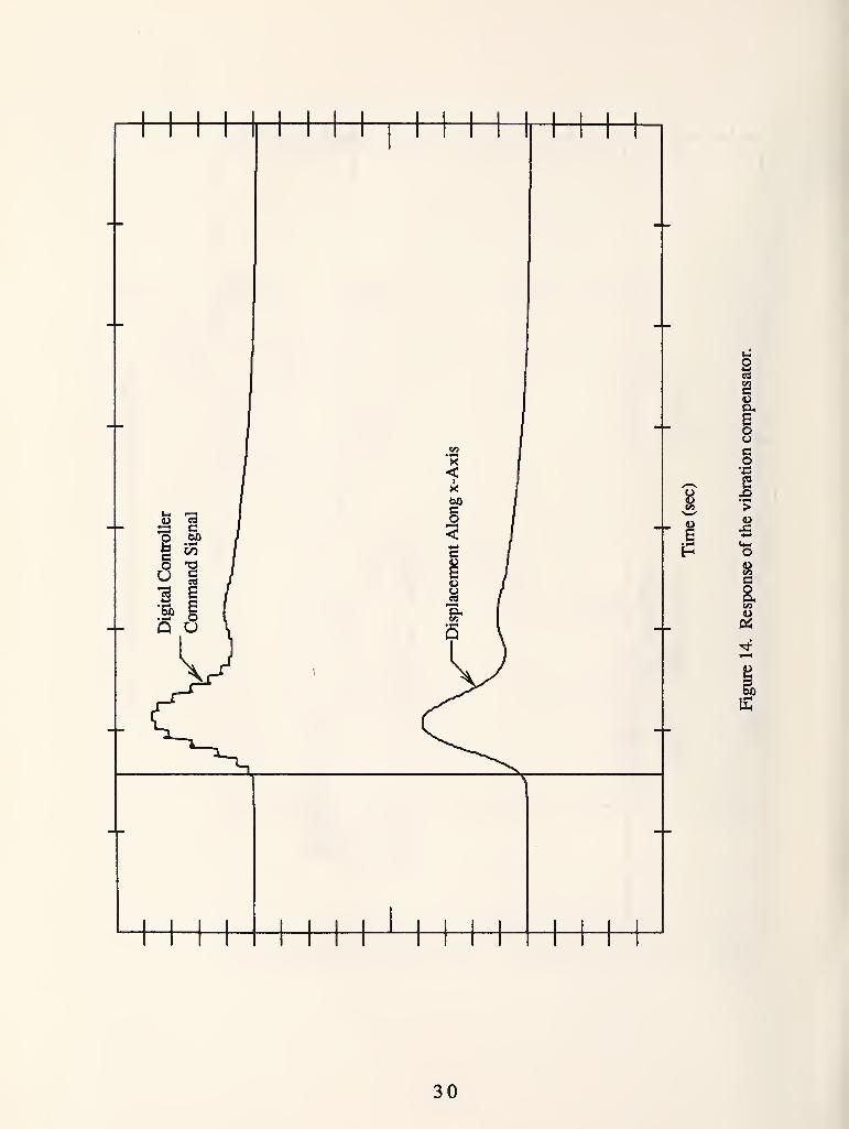
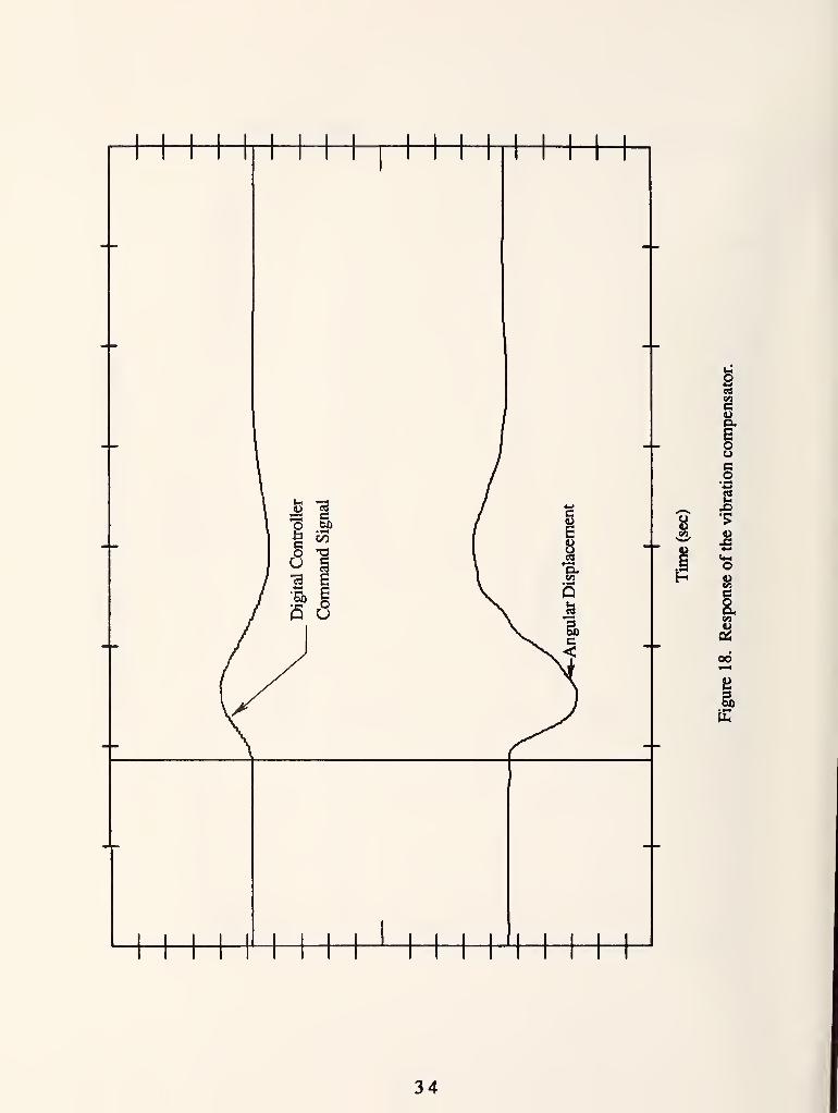
longitudinal axis (x-axis) of the steel beam with no digital controller action. Figure 14 shows the
response to a similar excitation with digital control action. Figure 15 shows the response of the
vibration compensator to an impulse excitation orthogonal to the longitudinal axis (y-axis) of the
steel beam with no digital controller action. Figure 16 shows the response to a similar excitation
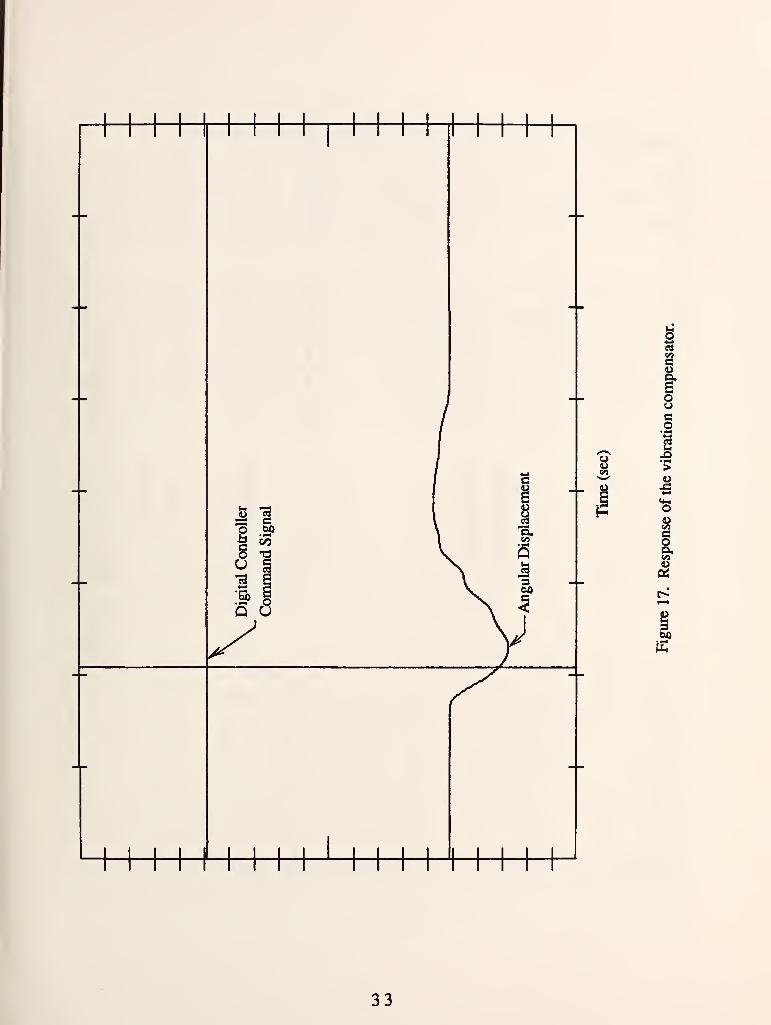
with digital control action. Figure 17 shows the response of the vibration compensator to an
impulse moment excitation along the vertical axis (z-axis) of the steel beam with no digital
controller action. Figure 18 shows the response to a similar excitation with digital control action.
As can be seen from these test results there is a significant improvement in the response of the
payload of the robot crane model to horizontal force excitation inputs, but not in the response to
moments about the vertical axis. An increase in the digital controller gain of that axis leads to more
oscillatory response and eventually instability. This points to the need to use more sophisticated
controller algorithms, at least for that last axis.
27
u
I
•fi
13
•S
6
aBauCO
i£^
28
« ac
o wisc CO
o T3U"eS a•Eh 1Q u
k
E
cu
Iouco«-•
2
ucoa,
rn
29
8
P
Ica,
iueo•43
COCoa.
I
30

p
c
ouc
2X)
x:
•n
s(90
31

4> 73sa c75 bX)
00
o TSU s-a g4->
'Eh Bo
Q u
CO
g
III•?
s
bO
32
iCOC
I§
I•5:
•s
uCO
I
i^
33
oC3
C/3
o '2U g13 €4-^
•5o 6
5 d
ICOC
Oco
I
ocoCO
00
34
4.4 Task IV
The objective of this task was to construct an intermediate-size robot crane model for factory
automation use. Suspend a robot arm from the lower crane platform, as shown in figure 2, and
demonstrate the capability to monitor the position of the robot arm end-effector, as it moves in
three-dimensional space, with noncontact sensors.
The largest size upper platform which could be suspended from the ceiling of our lab, without the
wireropes interfering with the Ught fixtures, was an equilateral triangle of 6-ft long side (B = 3 ft).
The diameter of the wireropes was selected to be 3/8 in. The height 12 ft 8 in was selected to allow
enough clearance between the robot arm end-effector and the floor. A PUMA-560 robot arm
which became available for this task weighs approximately 150 lb with its end-effector. This
allows us to suspend several hundred pounds of payload from the lower platform in addition to the
robot arm.
Since the robot arm is relatively short and has low manipulation power, no significant moments
were expected to be developed on the lower crane platform during its operation. Thus it was
decided to build a crane suspension system which is stiff to external forces rather than moments.
Based on the results of the optimization analysis that design could be achieved with a lower
platform which is one-half that of the upper platform (A =B/2 =1.5 ft). Figure 19 shows a picture
of the intermediate-size model with the robot arm hanging undemeath.
This type of robot crane design can be used for the automation of industrial operations. If the
upper platform is mounted on the carriage of a gantry crane the robot arm can be used to load and
unload several machine tools. Compared to the current practice of using dedicated robot arms to
load and unload machine tools this design could reduce the number of needed robots and free
valuable factory floor space for other use. By hanging a hook undemeath the lower platform, as
shown in figure 2, heavy parts and fixtures can be moved, and with the help of the robot arm be
accurately positioned. By mounting drills, deburring tools, etc., from the lower platform, the
lateral stiffness capability of the crane suspension can be used to do drilling, deburring, etc., on
sheet metal structures while the robot arm could hold vision or touch sensors to assist with the
machining operation. Similarly, vision or other sensors could be used for the inspection of large
structures, such as airplanes, ships, etc.
35
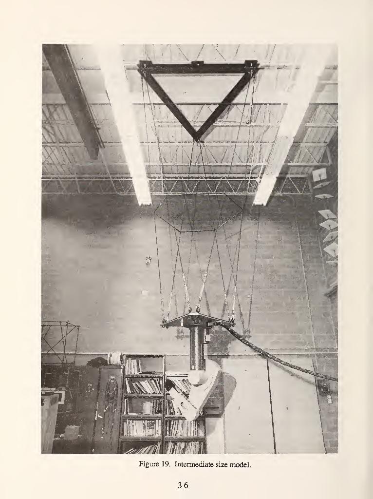
Figure 19. Intermediate size model.
36
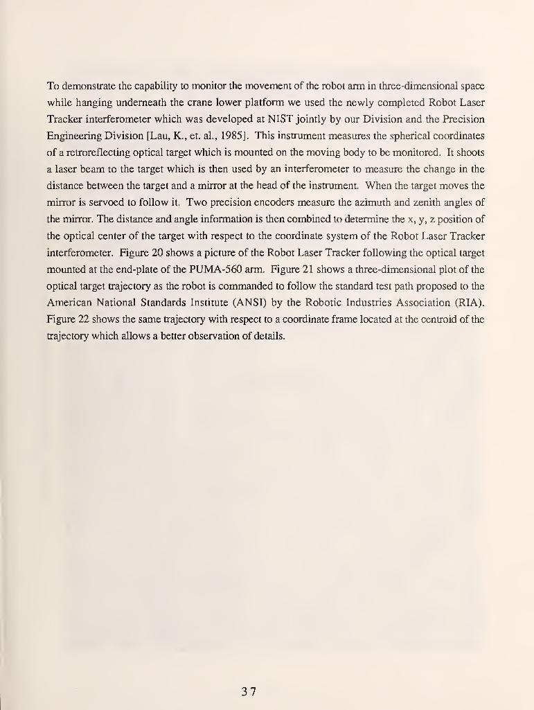
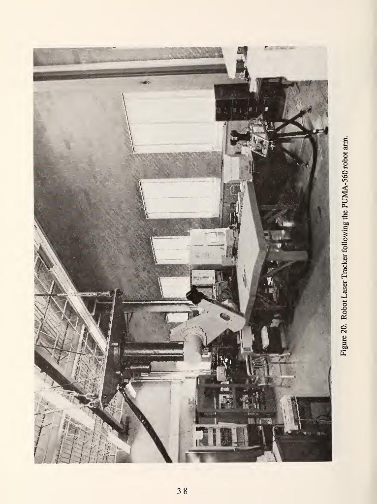
To demonstrate the capability to monitor the movement of the robot arm in three-dimensional space
while hanging underneath the crane lower platform we used the newly completed Robot Laser
Tracker interferometer which was developed at NIST jointly by our Division and the Precision
Engineering Division [Lau, K., et. al., 1985]. This instrument measures the spherical coordinates
of a retroreflecting optical target which is mounted on the moving body to be monitored. It shoots
a laser beam to the target which is then used by an interferometer to measure the change in the
distance between the target and a mirror at the head of the instrument. When the target moves the
mirror is servoed to follow it. Two precision encoders measure the azimuth and zenith angles of
the mirror. The distance and angle information is then combined to determine the x, y, z position of
the opdcal center of the target with respect to the coordinate system of the Robot Laser Tracker
interferometer. Figure 20 shows a picture of the Robot Laser Tracker following the optical target
mounted at the end-plate of the PUMA-560 arm. Figure 21 shows a three-dimensional plot of the
optical target trajectory as the robot is commanded to follow the standard test path proposed to the
American National Standards Institute (ANSI) by the Robotic Industries Association (RIA).
Figure 22 shows the same trajectory with respect to a coordinate frame located at the centroid of the
trajectory which allows a better observation of details.
37
oot-l
o
•S
o
Kl
«->
oo
o
38
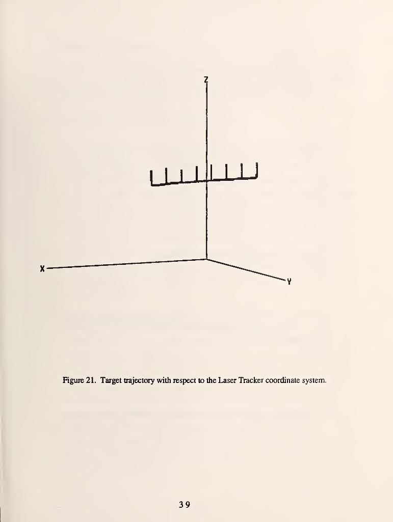
Figure 21. Target trajectory with respect to the Laser Tracker coordinate system.
39
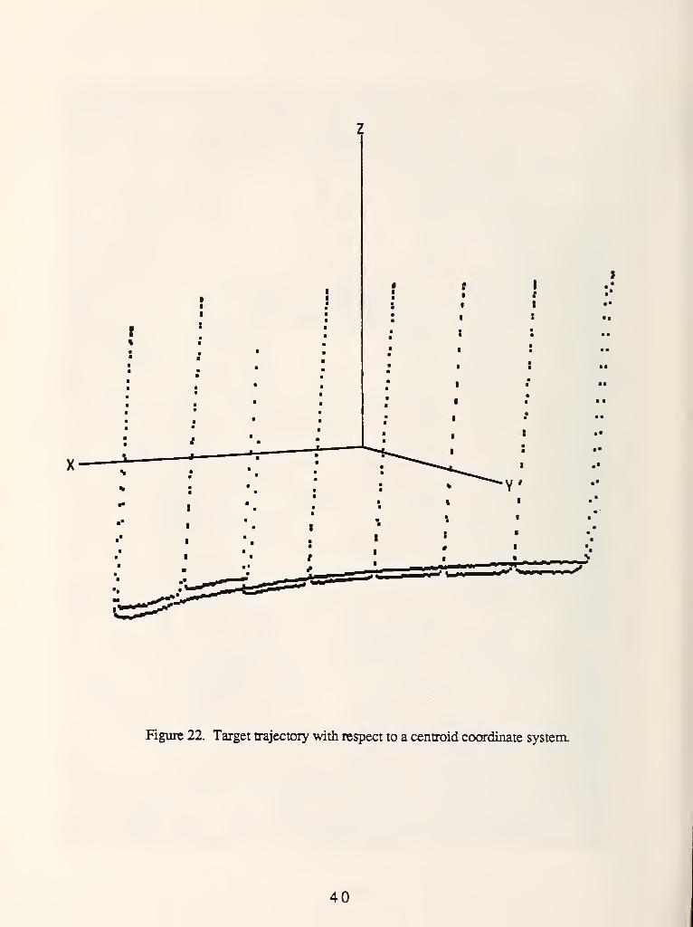
Figure 22. Target trajectory with respect to a centroid coordinate system.
40

5. Summary and Conclusions
The robot crane technology program has made good progress toward its objective of developing
kinematically constrained, dynamically stabilized, robot cranes capable of lifting, moving, and
positioning heavy loads, capable of supporting fabrication and construction operations.
Progress in the period from April 1 to November 31, 1988:
* A theoretical model of the proposed robot crane suspension mechanism has been
developed and tested with a full-size robot crane model. The stiffness of the crane
suspension mechanism of a full-size model was measured for two different types of
external loads and compared with the theoretical model predicted values. The full-size
model suspension consisted of six wireropes of 3/8-in diameter, which supported a total
load of approximately 19,000 lb, from a height of approximately 29 ft. The stiffness to
a horizontal extemal force and the stiffness to a moment about the vertical axis applied to
the lower suspended platform were measured. In the first case, the theoretical model
predicted stiffness is on the average 14.6% less than that measured by the experiment.
In the second case, the theoretical model's predicted stiffness is on the average 33.8%
less than that measured by the experiment. At the present the wireropes have been
replaced with new ones of 3/4-in diameter and a more thorough investigation of this
difference is planned.
* The proposed crane suspension stiffness optimization problem was formulated. The
optimization problem was studied for four different extemal loads. These were an
extemal horizontal force, an extemal vertical force, a moment about the vertical axis,
a moment about a horizontal axis, each of them applied to the lower suspended platform.
A global and a local maximum analysis study were conducted and general design mles
were formulated. The selection of the maximum stiffness design depends on the type of
extemal forces and moments which are expected to dominate the loading of the lower
crane platform. The most convenient way to proceed with the selection of a design is
probably to pick a few different sizes of the upper crane platform and then follow the
mles described in section 4.2 for the selection of the lower platform size. The
combination of the upper and lower platform with the highest stiffness should be the best
choice. The resuhs of the optimization search have been tabulated and can be used to
facilitate the design process.
41
* A three degrees-of-freedom robot crane payload vibration compensation device was
constructed and tested on a small crane model. This device consisted of a servo-driven
horizontal X-Y table and rotary joint about the vertical axis, which was suspended from
the model crane lower platform. The oscillations of the payload in the horizontal plane
and its rotations about the vertical axis were detected by extemal sensors and a digital
controller determined the appropriate command signals to the servo drives in order to
compensate them. A simple proportional gain digital controller algorithm was used for
this stage of the investigation. The gains were selected experimentally in order to
minimize the number and amplitude of the oscillations of the payload in the
corresponding direction. The payload response to force disturbances along the horizontal
plane showed a significant improvement when the vibration compensation control was
on. The payload response to moment disturbances about the vertical axis did not show
any noticeable improvement when the vibration compensation control was on.
* An intermediate-size model robot crane was constructed for factory automation
applications. Its upper platform was an equilateral triangle with a side length of 6 ft.
Based on the stiffness optimization study, the lower platform was selected to be one-half
the size of the upper platform. A PUMA-560 robot arm was suspended from the lower
platform of this model. A robot three-dimensional tracking laser interferometer was used
to monitor the movements of the arm in space and software was written to process
and display the path tracking data. The robot arm tumed out to be quite stiff to any type
of extemal disturbances. Above a certain level though the wireropes would buckle
making the arm yield ( see fig. 12 of [Dagalakis, N.G., et al., 1988]). This could be a
very desirable feature for applications where safety requires that the forces or moments
applied by the robot arm do not exceed certain limits.
Proposed future work:
* Theoretical study and measurement of the buckling characteristics of the robot crane
suspension mechanism.
* Design and testing of active damping and the micro-positioning control systems of an
intermediate scale crane platform.
* Add vision, touch, and force sensors and demonstrate the ability of a robot crane to load
and unload machine tools in a factory environment.
42

* Develop the proper sensors and grippers and demonstrate the ability of a robot crane to
pickup and deliver heavy fixtures in a factory environment.
* Develop the proper sensors and grippers and demonstrate the ability of a robot crane to
provide lateral support to do drilling, deburring, etc., of large and inaccessible sheet
metal structures.
* Retrofit a tower crane, develop the proper sensors and grippers and demonstrate the
ability of a robot crane to pickup and deliver heavy payloads of different shapes and
sizes for construction work.
43
6 . Acknowledgments
The robot crane technology program was funded by the Defense Advanced Research Projects
Agency, Information Science and Technology Office, ARPA order 6380. Dr. Robert L. Resenfeld
was the project sponsor.
We would like to acknowledge the help of the following people. Mr. Mitch Tarica for the design
and construction of most of the mechanical components used for this work and his help with some
of the experiments. Mr. Wendell Wallace for the construction of the vibration compensation
electrical system. Mr. Frank Rankin for his help with the construction of the full-size robot crane
model.
44
7 . References
Albus, J. S. A stabilized lifting platform. Internal Nat Bur. Stand (U.S.) Memo; 1987.
Aibus, J. S.; Dagalakis, N. G.; Wang, B-L; linger, J.; Lee, J. D.; Yancey, C. W. Available
robotics technology for applications in heavy industry. To be published by the Iron and Steel
Engineer; 1988.
Bennett, W. M. Mechanical wrist for a robot arm. Mech. Eng. DepL Mass. Inst of Tech. B.S.
Thesis; 1968.
Carbon, L. Automation of grab cranes. Siemens Review 43(2): 80-85; 1976 February.
Dagalakis, N. G.; Albus, J. S.; Wang, B-L; linger, J.; Lee, J. D. Stiffness study of a parallel link
robot crane for shipbuilding applications. Proc. Offshore Mechanics and Arctic Eng, Conf.; 1988
February; Houston, TX.
Fichter, E. F.; McDowell, E.D. A novel design for a robot arm. Proc. InL Computer Tech. Conf.:
250-256; 1980 August; San Fransisco, CA.
Fichter, E. F. Kinematics of a parallel connection manipulator. ASME Paper 84-DET-45 delivered
at the Design Eng. Tech. Conf.; 1984 October, Cambridge, MA.
Fichter, E. F. A Stewart platform based manipulator: General theory and practical construction.
The Kinematics of Robot Manipulators, MTT Press: 165-190; 1987.
"Gadfly- the Answer to Electronic Component Assembly," Assembly Automation: 20-22; 1983
February.
Gough, V.E., "Contribution to Discussion of Papers on Research in Auto Stability and Control
and in True Performance by Cornell Staff, Proc. Auto Div. Inst Mech. Eng., pp.392-403, 1956-
1957.
Gough, V. E.; Whitehall, S. G. Universal tyre test machine. Proc. 9th Int. Automobile Technical
Congress: 117-135; 1962.
45
Kogure, H.; Tojo, M. Recent developments in crane control. Hitachi Review 27(6): 315-320;
1978.
Koliskor, A. S. Development and investigation of industrial robots based on specification by 1-
coordinates. Soviet Engineering Research 2(12): 75-78; 1982.
Konstantinov, M. S.; Sotirov, Z. M.; Zamanov, V. B.; Nenchev, D. N. Force Feedback Control
of Parallel Topology Manipulating Systems. I*roc. 15th Int. Symp. on Industrial Robots: 181-188;
1985 September; Tokyo, Japan.
Kubo, M. Robots and computers to automate Japanese shipbuilding. Keynote address II, 6th Int.
Symp. on Offshore Mechanics and Arctic Engineering: 1987 March; Houston, TX.
Landsberger, S. E.; Sheridan, T. B. A new design for parallel link manipulators. Proc. Systems
Man and Cybernetics Conf.: 812-814; 1985 November, Tucson, AZ.
Lau, K.; Hocken, R.; Haynes, L. Robot end point sensing using a laser tracking system.
Proceedings of the Workshop on Robot Standards: 104-1 11; 1985 June; Detroit, MI.
McCallion, H.; Johnson, G. R.; Pham, D. T. A compliant device for inserting a peg in a hole. The
Industrial Robot : 81-87; 1979 June.
Multicraft A/S; Oslo, Norway.
Powell, I. L. The kinematic analysis and simulation of the parallel topology manipulator. The
Marconi Review XLV (226): 121-138; 3rd quarter 1982.
Sheridan, T. B. Human supervisory control of robot systems. Proc. Int. Conf. on Robotics and
Automation: 808-812; 1986 April; San Fransisco, CA.
Stewart, D. A platform with six degrees of freedom. Proc. of the Inst, of Mech. Eng. 180(15) Part
I: 371-386; 1965-1966.
U. S. Department of Commerce, International Trade Administration. 1987 U.S. Industrial
Outlook.
46

Unger, J.; Dagalakis, N. G.; Tsai, T. M.; Lee, J. D. Optimum stiffness study for a parallel link
robot crane under horizontal force. Proceedings of the 2nd Int. Symp. on Robotics and
Manufacturing: 1037-1046; 1988 November, Albuquerque, NM.
47

Appendix I
Development of the Vibration Compensation Signal Processing and Control
Algorithms
IV. 1 The Signal Processing Algorithms
The translation and rotation of the payload was measured by three Linear Voltage Differential
Transformers (LVDTs), which were fixed parallel to the floor and were positioned as shown in
figure 11 of the main report. The LVDT transducers measure the displacement of the moving core
of their electromagnet and produce an analog voltage signal which corresponds to its absolute
position.
Figure IV. 1 shows the steel beam, which supports the payload and the counterweight (for more
details refer to sec. 4.3 of the main report), and the three LVDTs. LVDTs 1 and 2 are positioned
parallel to each other with their sensor probe in contact with the same side surface of the beam,
while LVDT 3 is oriented with its axis orthogonal to the other two, so that its probe is in contact
with another side surface of the beam. To reduce friction the surface of the beam which comes in
contact with the LVDT probes was covered with Teflon tape. At the beginning of each test the
LVDT sensors were carefully positioned so that they are all at the same horizontal level and the
axes of their moving cores are orthogonal to the corresponding side of the beam.
Let (x\y, y\y, zb ) be a coordinate system fixed on the beam with origin located at (x^^, y^b* Zcb-^-
The location of the origin (x^\y, y^^, z^^) is measured from the absolute reference coordinate
system ( x , y , z ) fixed on the floor.
Any flat surface of the beam can be described by eq
%^b + ^byb + %^b = ^b '(^)
where a^, b^, c^ are the directional cosines of the surface normal and d^j is the distance of the
surface from the origin x^^j, y^^, z^,^.
Each LVDT sensor will give the coordinate ( x , y , z ) of the contact point between the sensor
probe and the beam side surface, measured with respect to the absolute reference coordinate frame.
49
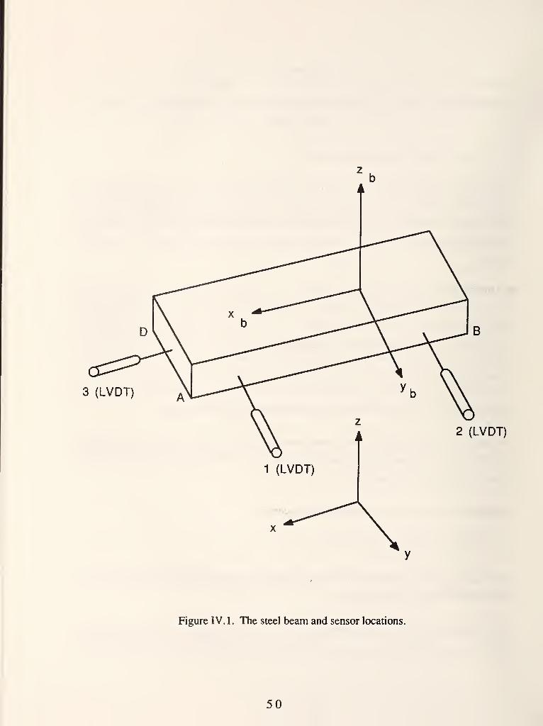
3 (LVDT)
2 (LVDT)
Figure IV.l. The steel beam and sensor locations.
50
The transfonnation between the absolute coordinate ( x , y , z ) and the beam coordinate (x^, y^,
z\y) is given by
Xb
yb
^b J
•^xx ^xy 'xz
^yx "^yy ^yz
L '^zx '^zy '^zz
y-ycb
z-^cb
(2)
where n^x. ^zz ^® ^® directional cosines between the two sets of coordinate axes, x y z
and Xb yb Zb-
The coordinates (xb, yb. ^b) of the contact point between the sensor probe and the beam surface
must satisfy eq (1), i.e.
[ ^b ^b ]
'^b
yb
^b J
= db- (3)
Considering only small amplitude oscillations of the lower crane platform it was assumed that the
motion of the beam can be approximated by a translation on a horizontal plane and a rotation about
a vertical axis. LVDT sensor 1 and 2 were in contact with surface AB of the beam and could
measure its angular displacement. Sensor 3 was in contact with surface AD of the beam and in
conjunction with sensors 1 and 2 can measure its translation.
Determination of the Beam Angular Displacement
Let the normals to surfaces AB and AD with respect to the beam coordinate frame be (aj, bj, 0)
and (a3, b3, 0), respectively. The unit vector (nj^b^ Oyb, 0) of the line segment connecting the
contact points between sensor probes 1, 2 and surface AB, with respect to the beam coordinate
frame, is perpendicular to the surface normal (ai,bi,0). Therefore,
(nxb,nyb,0) = (-bi,ai,0). (4)
51
As the beam with the payload moves, its motion can be described by rotation matrices and
translation vectors. At any time, die unit vector of the line connecting sensor probes 1 and 2, widt
respect to the refei^mce coordinate frame, can be vqnesented by
"y
J
cosOj
- sinOj
sin6|
cosO|
1 J
n t
y
L
(5)
Where 6 lis die angular displacement of the beam far a rotation about the vertical axis. Provided
that sensor probes 1 and 2 always maintain contact with surface AB the unit vector (n^, Uy, 0) is
direcdy related to the positions measured by the sensor probes 1 and 2. The relations are given by
% =
ny =
X2-X1
^(x2-xi)2 + (y2-yi)^
y2-yi
^(x2-xi)2 + (y2-yi)^
(6.a)
(6.b)
From eqs (4) and (5),
--bi ai
. ai bi J
cos6i
sin61 J
n.
L ^ J
(7)
ThcrcfoK, the angle of the beam rotation can be obtained diiecdy by solving eq (7).
cos6i =
sinOj =
-bi n1 "x + ai n,
(ai
bj n,
+ bi2)
(8)
(ai2 + bi2)
52
DeterminatioD of the Beam Translation
Let (x^, y^) be 1}^ cooidiiialBS of apoint located on die beam, with lespect to the beam coordinate
firame. The cooidiiiates of diat same point with respect to die reference cooidinate firame are given
by
X
y J
cosOj sinO}
- sinO| cosO} [:]*[:;] (9)
Where 6| rqnesents the angular displac^nent of the beam cocnlinate frame with respect to the
refer^ice coordinate frame, and (uj, V|) the vecter of translation between die same frames.
To detenmne (ax, vj) , die eqs repres«iting the soi&ces to which the soisor probes are in ccmtact
must be used. Again, assuming a two-dimensicmal motion case, the relevant surfaces are
T^nesQited by
Smfece AB: aj X12'' + biyi2^ = dj
Surface AD: a3 13^ + b3 y3^ = d3
(10.a)
(lO.b)
Where (x12^, y12'') is a beam point located on surface AB and (X3'', y3'') is a beam point located
on surface AD. Substituting eq (9) into eqs (10.a) and (lO.b), gives
aiI(^12-ai)«Kei - (yi2-vi)sin8i] + bj [ (xi2 - ^1) sinOj + (yi2-vi)
cosBi ]= dj (ll.a)
a3 [ (x3 - uj) cos8i - (y 3- vj) sinSj ] + b3 [ (X3 - uj) sinGj + (ys - vj) cosGj ]
= d3 (ll.b)
fr^me and (X3, y3) are ihe oxHdinates of a point located csa surface AD with respect to the
refeu^ice frame.
53

After rearranging terms, eqs (11a and b) become
(aj cosGj + bj sinBj) u^ + (-a^ sinGj + bj cosSj) vj
= (aj cosGj + bj sinGj) X12 + (-aj sinGj + bj cos9 j) yi2 + dj (12.a)
(a3 cosG^ + b3 sin6j) uj + (-sl^ sinOj + b3 cosGj) vj
= (a3 cos9J+ b3 sin6j) X3 + (-a3 sin9j + b3 cos6j) y3 + d3 (12.b)
The sensor readings must satisfy eqs (12a and b).
Let (xj, yj, 0), (x2, y2» 0), (X3, y3, 0), be the sensor readings of probe 1, 2, 3, respectively.
Then
^2^1 + ^2^1 = §2
^3 "1 + ^3 ^1 = ^(13)
where
^2 = ^1 = aj cosGj + bj sinGj
T|2 = T|i = - a^ sinGj + bj cosGi
^3 = a3 cosGj + bj cosGj
TI3 = - 33 sinGj + b3 cosGj
^1 = ^1 ^1 + T|i Yi + dj
^2 = fe X2 + Ti2 y2 + d2
53 = ^3 ^3 + ^3 ys + ^3
Rewriting eq (13), gives
^1 ^1"
81
^2 ^2
" "1 -
. ^1 .
= 82
h ^3 - - 83 -
(14)
54
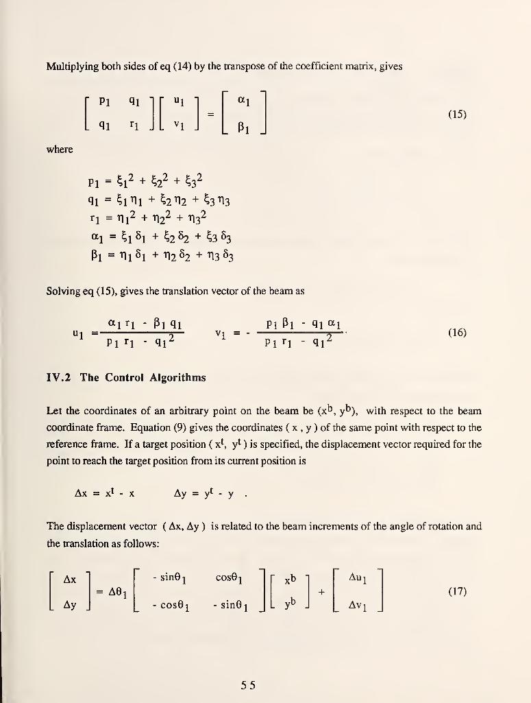
Multiplying both sides of eq (14) by the transpose of the coefficient matrix, gives
'Pi qi"
. qi ^1 .
=«i
. pi -
where
Pi = ^1^ + ^2^ + fe^
11 = ^1^1 + ^2^2 + ^3^3
ri = Tli^ + ^^ + 1132
«1 = ^1 ^1 + kih + ^3 S3
Pi = ^1^1 + TI2S2 + 113 S3
Solving eq (15), gives the translation vector of the beam as
(15)
ui =«in - Pi qi
Pl ri - qi^Vl =
Pl Pl - qi ^\
Pl n - qi^(16)
IV.2 The Control Algorithms
Let the coordinates of an arbitrary point on the beam be (x^, yb)^ with respect to the beam
coordinate frame. Equation (9) gives the coordinates ( x , y ) of the same point with respect to the
reference frame. If a target position ( x^, yt) is specified, the displacement vector required for the
point to reach the target position from its current position is
Ax = x^ Ay = y= vt .
The displacement vector ( Ax, Ay ) is related to the beam increments of the angle of rotation and
the translation as follows:
Ax= AGj
- sinGj cos9j xb -
+
Auj
Ay J- cosG]^ - sinGj [
yb\ Av^
(17)
55
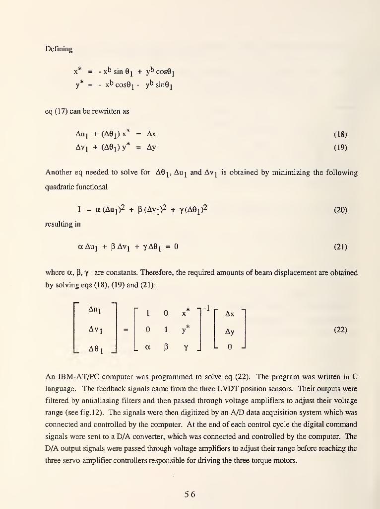
Defining
X =
y =
- xt> sin 0j + ybcos0j
- x^ cos9j - yt> sinGj
eq (17) can be rewritten as
Auj + (AGj) X = Ax
Avj + (AGj) y* = Ay
(18)
(19)
Another eq needed to solve for AGj, Auj and Avj is obtained by minimizing the following
quadratic functional
I = a(Aui)2 + P(Avi)2 + y(AGi)2
resulting in
aAu^ + pAvj + yAG^ =
(20)
(21)
where a, P, y are constants. Therefore, the required amounts of beam displacement are obtained
by solving eqs (18), (19) and (21):
Au1
Av
AG1 J
n-1 r-1 X
J.
Ax
1*
y Ay
a P y _ -
(22)
An IBM-AT/PC computer was programmed to solve eq (22). The program was written in C
language. The feedback signals came from the three LVDT position sensors. Their outputs were
filtered by antialiasing filters and then passed through voltage amplifiers to adjust their voltage
range (see fig. 12). The signals were then digitized by an A/D data acquisition system which was
connected and controlled by the computer. At the end of each control cycle the digital command
signals were sent to a D/A converter, which was connected and controlled by the computer. The
D/A output signals were passed through voltage amplifiers to adjust their range before reaching the
three servo-amplifier controllers responsible for driving the three torque motors.
56

Several square pulse excitation tests were conducted to tune the servo amplifiers and the digital
controller. The rise and fall times of the x-y table servo joints for a square pulse amplitude which
was 40% of the maximum command signal amplitude were approximately 0.8 seconds. The
corresponding times for a square pulse amplitude which was 100% of the maximum command
signal amplitude for the rotary joint was 2.5 seconds.
<JU . S . GOVERNMENT PRINTING F F I C E i 1 9 8 9- 2 4 2 - 2 / 4
3
57


NBS-IMA (REV. 2-80)
U.S. DEPT. OF COMM.
BIBLIOGRAPHIC DATASHEET (See instructions)
PUBLICATION ORREPORT NO.
NIST/TN-1267
2. Performing Organ. Report No. 3. Publication Date
July 1989
4. TITLE AND SUBTITLE
ROBOT CRANE TECHNOLOGY PROGRAM
(FINAL REPORT)
5. AUTHOR(S) Nicholas Dagalakis, James S. Albus. Kenneth R. Goodwin, James D. Lee,
Tsung-Ming Tsai, Hoosh Abrishamian, Roger Bostelman, Charles Yancey
6. PERFORMING ORGANIZATION (If joint or otiier than NBS. see instructions)
NATIONAL INSTITUTE OF STANDARDS AND TECHNOLOGY(formerly NATIONAL BUREAU OF STANDARDS)U.S. DEPARTMENT OF COMMERCEGAITHERSBURQ, MO 20899
7. Contract/Grant No.
8. Type of Report & Period Covered
Final
9. SPONSORING ORGANIZATION NAME AND COMPLETE ADDRESS (Street. City, State, ZIP)
Defense Advanced Research Projects Agency (DARPA)
1400 Wilson Blvd.
Arlington, VA 22209-2308
10. SUPPLEMENTARY NOTES
I I
Document describes a computer program; SF-185, FlPS Software Summary, is attached.
11. ABSTRACT (A 200-word or less factual summary of most significant information. If document includes a significantbibliography or literature survey, mention it here)
, , -i • , .
The effort to develop kinematically constrained, dynamically stabilized, robot
cranes capable of lifting, moving and positioning heavy loads over large volumes,
capable of supporting fabrication tools and the inspection of large size and
difficult to reach structures, is described in this report.
The approach taken was to build on previous work at the NIST Robot Systems Division
which has analyzed and measured the stiffness of a small model six-cable suspension
system. The system is a modified Stewart platform.
Under DARPA sponsorship, we have:
1. Extended this work to measure and optimize the stiffness of full-size models.
2. Actively damped oscillations in a small scale six-cable suspension platform.
3. Constructed an intermediate sized six-cable suspension platform for an
industrial robot.
12. KEY WORDS (Six to twelve entries; alphabetical order; capitalize only proper names; and separate key words by semicolons)
automation; construction; crane; factory; model; robot; stiffness; testing
13. AVAILABILITY
rj(] Unlimited
I I
For Official Distribution. Do Not Release to NTIS
K~] Order From Superintendent of Documents, U.S. Government Printing Office, Washington, D.C.20402.
12Z\ Order From National Technical Information Service (NTIS), Springfield, VA. 22161
14. NO. OFPRINTED PAGES
60
15. Price
USCOMM-DC 6043-PBO


NIST.Technical Publications
Periodical
Journal of Research of the National Institute of Standards and Technology—Reports NIST research
and development in those disciplines of the physical and engineering sciences in which the Institute
is active. These include physics, chemistry, engineering, mathematics, and computer sciences.
Papers cover a broad range of subjects, with major emphasis on measurement methodology andthe basic technology underlying standardization. Also included from time to time are survey articles
on topics closely related to the Institute's technical and scientific programs. Issued six times a year.
Nonperiodicals
Monographs—Major contributions to the technical literature on various subjects related to the
Institute's scientific and technical activities.
Handbooks—Recommended codes of engineering and industrial practice (including safety codes) de-
veloped in cooperation with interested industries, professional organizations, and regulatory bodies.
Special Publications—Include proceedings of conferences sponsored by NIST, NIST annual reports,
and other special publications appropriate to this grouping such as wall charts, pocket cards, andbibliographies.
Applied Mathematics Series—Mathematical tables, manuals, and studies of special interest to physi-
cists, engineers, chemists, biologists, mathematicians, computer programmers, and others engaged in
scientific and technical work.
National Standard Reference Data Series—Provides quantitative data on the physical and chemicalproperties of materials, compiled from the world's literature and critically evaluated. Developed un-
der a worldwide program coordinated by NIST under the authority of the National Standard DataAct (Public Law 90-396). NOTE: The Journal of Physical and Chemical Reference Data (JPCRD)is published quarterly for NIST by the American Chemical Society (ACS) and the American Insti-
tute of Physics (AIP). Subscriptions, reprints, and supplements are available from ACS, 1155 Six-
teenth St., NW., Washington, DC 20056.
Building Science Series—Disseminates technical information developed at the Institute on building
materials, components, systems, and whole structures. The series presents research results, test
methods, and performance criteria related to the structural and environmental functions and the
durability and safety characteristics of building elements and systems.
Technical Notes—Studies or reports which are complete in themselves but restrictive in their treat-
ment of a subject. Analogous to monographs but not so comprehensive in scope or definitive in
treatment of the subject area. Often serve as a vehicle for final reports of work performed at NISTunder the sponsorship of other government agencies.
Voluntary Product Standards—Developed under procedures published by the Department of Com-merce in Part 10, Title 15, of the Code of Federal Regulations. The standards establish nationally
recognized requirements for products, and provide all concerned interests with a basis for commonunderstanding of the characteristics of the products. NIST administers this program as a supplementto the activities of the private sector standardizing organizations.
Consumer Information Series—Practical information, based on NIST research and experience, cov-ering areas of interest to the consumer. Easily understandable language and illustrations provide use-
ful background knowledge for shopping in today's technological marketplace.Order the above NIST publications from: Superintendent ofDocuments, Government Printing Office,
Washington, DC 20402.
Order the following NISTpublications—FIPS and NISTIRs—from the National Technical Information
Service, Springfield, VA 22161.
Federal Information Processing Standards Publications (FIPS PUB)—Publications in this series col-
lectively constitute the Federal Information Processing Standards Register. The Register serves as
the official source of information in the Federal Government regarding standards issued by NISTpursuant to the Federal Property and Administrative Services Act of 1949 as amended. Public Law89-306 (79 Stat. 1127), and as implemented by Executive Order 11717 (38 FR 12315, dated May 11,
1973) and Part 6 of Title 15 CFR (Code of Federal Regulations).
NIST Interagency Reports (NISTIR)—A special series of interim or final reports on work performedby NIST for outside sponsors (both government and non-government). In general, initial distribu-
tion is handled by the sponsor; public distribution is by the National Technical Information Service,
Springfield, VA 22161, in paper copy or microfiche form.

U.S. Department of CommerceNational Institute of Standards and Technology
(formerly National Bureau of Standards)
Gaithersburg, MD 20899
Official Business
Penalty for Private Use $300