Embed Size (px)
Citation preview

Robinetteriede sécurité
Safety check valves
Matériel conforme à la directive
PED - 97/23/CE
Version ATEX conforme à la directive
94/9/CE, disponible sur demande.
ATEX version according to directive 94/9/CE,
available on request.
R O B I N E T T E R I E I N D U S T R I E L L ER O B I N E T T E R I E I N D U S T R I E L L E
I N D U S T R I A L V A L V E S
S A F E T Y D E V I C E

SOMMAIRE / SUMMURY
PREAMBULE / PREAMBLE
Clapets anti-retour Sécurité Feu / Fire Safe Check Valves
SEPARFEU® « Bac sortie » / SEPARFEU® « Tank Outlet »Sécurité positive lors de l’exploitation des bacs de stockagePositive security during tank working
BABE® « Bac à Bac » / BABE® « Tank to Tank »Sécurité positive lors des transferts de bac à bacPositive security during transfering from tank to tank
ET® « Clapet d’entrée » / ET® « Inlet check valve »Clapet anti-retour sécurité feu - Encombrement standardFire safe check valve standard face to face
EB® « Clapet d’entrée » / EB® « Inlet check valve »Clapet anti-retour sécurité feu - Encombrement spécialFire safe check valve special face to face
Vannes de sécurité / Safety Valves
SEPARSAFE® / SEPARSAFE®
Sécurité positive lors des opérations de distributionPositive security during distribution
2
La protection des personnes,des biens et de l’environnement a conduit les autorités compétentesà édicter une réglementation très stricte concernant l’installation obligatoire de systèmes defermeture des canalisations de pied de bac.De ce fait, la mise en sécurité des équipements de stockage et de distribution est réglementéepar l’instruction ministérielle du 09-11-1989 dont voici un extrait :
Fires in storage depots for hydrocarbons or volatile fluid fires can reachcatastrophic proportions with great speed. It is esssential to stop theflow of the liquid as rapidly as possible in order to cut off the supplyof fuel to the fire and check pollution of the soil at an early stage.This operation is practically impossible if the system does not incorporatea positive security valve,passively actuated by an abnormal temperaturerise or by remote control.
Art 17 : Lors d’accidents survenant en périoded’exploitation, des grandes difficultés apparais-sent pour l’extinction des feux alimentés. Pourprévenir ces inconvénients notamment dans le casde rupture de conduites, la mise en place de vannesde pied de bac à sectionnement rapide doit êtreimposée : des systèmes de cette nature ont étégénéralisés dans les dépôts de grandes compagnies.Les vannes de pied de bac doivent être de typesécurité feu commandables à distance et à sécuritépositive.
Document non contractuel.
Tél. 00 33 (0)3 85 67 31 00 Fax 00 33 (0)3 85 57 06 82
E-mail : [email protected] : www.buracco.comR O B I N E T T E R I E I N D U S T R I E L L ER O B I N E T T E R I E I N D U S T R I E L L E
I N D U S T R I A LI N D U S T R I A L V V A LA L V E SV E S
S A F E T Y D E V I C ES A F E T Y D E V I C E

3
SEPARFEU® « Bac sortie » / SEPARFEU® « Tank Outlet »
GAMME / RangeDN 50 à 1000
Corps : C35, Inox 316 L
Battant : Acier moulé C35,Inox 316 L
Axe : Inox Z20 C13, Uranus 45 N
Siège : Métal / Métal
Protection : Epoxy
ISO PN 10-16 ASA 150
Pression de service : PS 3 bar
CARACTERISTIQUES TECHNIQUES / Technical Specifications
ESSAIS / Test Report
Construction Sécurité Feu selon les normes BS 6755 Part2 - API SPEC 6 FA - SNEAP TUY. FO2.
Conception et essais selon API 594 et API 598.
Construction ATEX selon la directive européenne 94/9/CEZone 1 ou 21,Groupe 2,Catégorie 2 G/D.(Sur demande).
Fusion du fusible à 138° C.
Montage du mécanisme à gauche ou à droite parrapport au sens d’écoulement du fluide.
Possibilité de réinjecter des produits extincteurs depuisl’aval après fermeture.
Équipement de base à sécurité positive par thermo-fusible.
Commande de déclenchement électrique à distancepar électrovanne ou électroaimant en option.
Réarmement manuel par levier ou par systèmehydraulique.
Contacts de fin de course inductifs en option
Fire safe designed according to BS 6755 PART. 2 - API SPEC 6FA - SNEAP TUY. FO2.
Designed and tested according to API 594 - API 598.
ATEX designed according to european directive 94/9/CEZone 1 or 21, Group 2, category 2 G/D. (On request).
Fuse melting at 138°C.
Mechanism can be on the right or on the left relative to thefluid flow.
Downstream injection possible after closure.
Basic equipment with fuse, positive security.
Electric triggered at distance by solenoid valve or electromagnet.
Manuel re-setting by handle or by hydraulic device.
Proximity switch in option.
ND 50 to 1000
Body : Steel C35, SS 316 L
Clapper : Cast Steel C35,SS 316 L
Shaft : SS Z20 C13, Uranus 45 N
Metal / Metal Seat
Epoxy coating
ISO PN 10-16 - ASA 150
Working pressure : 3 bar
Test d’étanchéité selon API 598, taux de fuite3 cm3/inch/min.
Essai hydraulique au CETIM N° 6023261/661/4A.
Essai feu TUV du 06/02/95.
Essai feu Elf Aquitaine Production du 18/10/94.
Pressure test according to APSI 598 leakage rate 3 cm3/inch/min.
Hydraulic test N° 6023261/661/4A.
Fire test TUV 06/02/95.
Fire test Elf Aquitaine Production 18/10/94.
Document non contractuel.
Tél. 00 33 (0)3 85 67 31 00 Fax 00 33 (0)3 85 57 06 82
E-mail : [email protected] : www.buracco.comR O B I N E T T E R I E I N D U S T R I E L L ER O B I N E T T E R I E I N D U S T R I E L L E
I N D U S T R I A LI N D U S T R I A L V V A LA L V E SV E S
S A F E T Y D E V I C ES A F E T Y D E V I C E

SEPARFEU® « Bac sortie » / SEPARFEU® « Tank Outlet »
MONTAGE / Mounting
Le clapet de pied de bac SEPARFEU® est installé au plus près du bac, sur la tuyauterie d’exploitation.Il assure l’isolement automatique et autonome du bac en cas de nécessité ou de danger.La fermeturepeut être provoquée soit par la destruction d’un fusible en cas d’élévation de la température, soitpar un déclenchement à distance par électrovanne par manque de courant ou par impulsion, oupar électroaimant à manque de courant.Aucune source d’énergie n’est nécessaire pour la fermeture,le clapet se ferme sous l’effet de la gravité. Le réarmement est manuel par l’intermédiaire d’un levierou automatiquement à l’aide d’un système hydraulique.
The SEPARFEU® safety check valves must be installed nearly the tank on the outlet bottom pipe.In case of fire or dangerous damages, it stop the liquid flow automaticly and operates independently by themelting of the fuse plug or from distance by a variety of electrical or pneumatical devices.No energy is required the combination of the natural force of gravity, the mass of the flap and the movmentof the fluid is enough to closed the safety check valves.Reseting is made by hand lever or automaticly with an hydraulic device.
Avantages :- Aucun risque de surpression entre
le clapet et la vanne.
- Protection aval des vannes ettuyauteries.
- Option recommandée pour touteinstallation neuve.
Advantages : - No risk of surpression between gate
valve and check vavle.
- Downstream protection of valves andpipes.
- Recommended option for newinstallation.
Montage en amont de la vanne d’exploitation.Montage préférentiel car le clapet est au plus prèsdu bac.
Upstream mounting from the working gate valve.Preferential mounting because the check valve is just nearthe tank.
Montage en aval de la vanne d’exploitation :
Montage possible lorsque la vidange du bac n’est pas réalisable.
- Aucune interférence avec la vanne à passage direct d’exploitation.
- Le battant du clapet est équipé d’une soupape afin d’éviter les surpressions entre le clapet et la vanne
Downstream mounting from the working gate valve :
Acceptable mounting when tank emptying is not possible
- Without interference with the gate valve.
- Clapper with discharge vavle to avoid over pressure between gate valve and check valve
4 Document non contractuel.
Tél. 00 33 (0)3 85 67 31 00 Fax 00 33 (0)3 85 57 06 82
E-mail : [email protected] : www.buracco.comR O B I N E T T E R I E I N D U S T R I E L L ER O B I N E T T E R I E I N D U S T R I E L L E
I N D U S T R I A LI N D U S T R I A L V V A LA L V E SV E S
S A F E T Y D E V I C ES A F E T Y D E V I C E
5
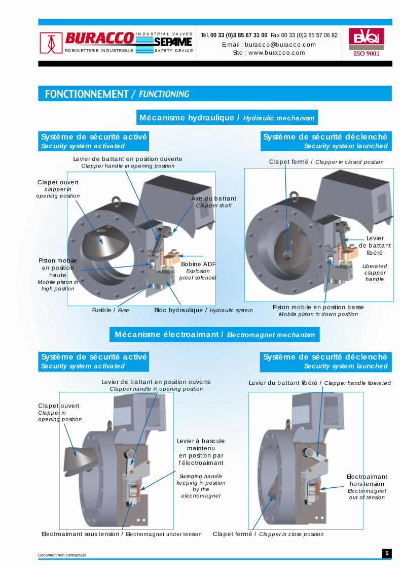
FONCTIONNEMENT / FUNCTIONING
Mécanisme hydraulique / Hydraulic mechanism
Mécanisme électroaimant / Electromagnet mechanism
Levier de battant en position ouverteClapper handle in opening position
Clapet ouvertClapper in opening position
Levier de battant en position ouverteClapper handle in opening position
Levier du battant libéré / Clapper handle liberated
Electroaimanthors tension
Electromagnet out of tension
Clapet fermé / Clapper in close position
Piston mobileen position
hauteMobile piston in
high position
Clapet ouvertclapper in
opening position
Fusible / Fuse
Bobine ADFExplosion
proof solenoid
Axe du battantClapper shaft
Bloc hydraulique / Hydraulic system Piston mobile en position basseMobile piston in down position
Levier de battant
libéré
Liberatedclapperhandle
Clapet fermé / Clapper in closed position
Levier à basculemaintenu
en position par l’électroaimant
Swinging handlekeeping in position
by theelectromagnet
Electroaimant sous tension / Electromagnet under tension
Système de sécurité activéSecurity system activated
Système de sécurité déclenchéSecurity system launched
Système de sécurité activéSecurity system activated
Système de sécurité déclenchéSecurity system launched
Document non contractuel.
Tél. 00 33 (0)3 85 67 31 00 Fax 00 33 (0)3 85 57 06 82
E-mail : [email protected] : www.buracco.comR O B I N E T T E R I E I N D U S T R I E L L ER O B I N E T T E R I E I N D U S T R I E L L E
I N D U S T R I A LI N D U S T R I A L V V A LA L V E SV E S
S A F E T Y D E V I C ES A F E T Y D E V I C E

6
∆P = Equivalent longueur en mètre de tuyauterie∆P = Pipe lenght equivalent in meter
ENCOMBREMENT / Dimension
DN Size Ø A B Ø C D E Kv ∆P POIDS
mm Inch mm mm mm mm mm m3/h m Weight65 2 1/2" 200 105 46 325 0 92 3 m 35 kg80 3" 200 73 53 325 35 127 3 m 30 kg100 4" 229 73 72 333 56 310 3 m 38 kg150 6" 279 98 116 351 85 750 4 m 45 kg200 8" 343 127 156 337 102 1130 7 m 75 kg250 10" 406 150 200 370 140 2070 7 m 114 kg300 12" 483 195 234 416 138 2660 9 m 190 kg350 14" 533 220 262 433 155 4040 10 m 250 kg400 16" 597 250 294 460 162 5260 12 m 340 kg450 18" 635 297 346 479 174 7150 13 m 520 kg500 20" 698 327 380 510 202 9400 15 m 560 kg600 24" 813 347 467 580 275 13160 17 m 950 kg700 28" 927 350 580 790 300 18000 20 m 1500 kg800 32" 1060 350 690 815 460 20000 35 m 1700 kg900 36" 1168 400 895 920 500 25000 50 m 1850 kg1000 40" 1289 500 980 1030 600 30000 60 m 1970 kg
Document non contractuel.
Tél. 00 33 (0)3 85 67 31 00 Fax 00 33 (0)3 85 57 06 82
E-mail : [email protected] : www.buracco.comR O B I N E T T E R I E I N D U S T R I E L L ER O B I N E T T E R I E I N D U S T R I E L L E
I N D U S T R I A LI N D U S T R I A L V V A LA L V E SV E S
S A F E T Y D E V I C ES A F E T Y D E V I C E

7
SEPARFEU® « Bac à Bac » / SEPARFEU® « Tank to Tank »
GAMME / Range
CARACTERISTIQUES TECHNIQUES / Technical Specifications
ESSAIS / Test Report
DN 80 à 800
Corps : Acier moulé C35,Inox 316 L
Battant : Acier C35, Inox 316 L
Axe : Inox Z20 C13, Uranus 45 N
Siège : Métal / Métal
Protection : Epoxy
ISO PN 10-16 ASA 150
Pression de service : PS 3 bar
Construction Sécurité Feu selon les normes BS 6755 Part2 - API SPEC 6 FA - SNEAP TUY. FO2.
Conception et essais selon API 6D - API 594 et API 598.
Construction ATEX selon la directive européenne 94/9/CEZone 1 ou 21, Groupe 2, Catégorie 2 G/D.
Fusion du fusible à 138° C.
Montage du mécanisme à gauche ou à droite parrapport au sens d’écoulement du fluide.
Possibilité de réinjecter un liquide extincteur depuisl’aval après fermeture.
Equipement de base avec fusible.
Commande manuel par levier ou réducteur débrayable.
Contacts de fin de course inductifs en option.
Fire safe designed according to BS 6755 PART. 2 - API SPEC 6FA - SNEAP TUY. FO2.
Designed and tested according to API 6D - API 594 - API 598.
ATEX designed according to european directive 94/9/CEZone 1 or 21, Group 2, category 2 G/D.
Fuse melting at 138°C.
Mechanism can be on the right or on the left relative to thefluid flow.
Downstream injection possible after closure.
Basic equipment with fuse.
Operating by handle or hand clutch manual gear box.
Proximity switch in option.
ND 80 to 800
Body : Cast Steel C35, SS 316 L
Clapper : Steel C35, SS 316 L
Shaft : SS Z20 C13, Uranus 45 N
Metal / Metal Seat
Epoxy coating
ISO PN 10-16 - ASA 150
Working pressure : 3 bar
Test d’étanchéité selon API 598, taux de fuite3 cm3/inch/min.
Essai hydraulique au CETIM N° 6023261/661/4A.
Essai feu TUV du 06/02/95.
Essai feu Elf Aquitaine Production du 18/10/94.
Pressure test according to APSI 598 leakage rate3 cm3/inch/min.
Hydraulic test N° 6023261/661/4A.
Fire test TUV 06/02/95.
Fire test Elf Aquitaine Production 18/10/94.
Document non contractuel.
Tél. 00 33 (0)3 85 67 31 00 Fax 00 33 (0)3 85 57 06 82
E-mail : [email protected] : www.buracco.comR O B I N E T T E R I E I N D U S T R I E L L ER O B I N E T T E R I E I N D U S T R I E L L E
I N D U S T R I A LI N D U S T R I A L V V A LA L V E SV E S
S A F E T Y D E V I C ES A F E T Y D E V I C E

8
CLAPET B.A.B.E. - BAC A BAC ENTREE - / CHECK VALVE FOR TANK TO TANK INLET
Mise en situation / Demonstration
Configuration / Configuration
Monté en Entrée de Bac, ceclapet est en position libre lors duremplissage du bac, il agit alorscomme un clapet anti-retourclassique.
Mounted at the tank inlet, this valve is infree position during filling of the tank,when it acts as a conventional no-returnflap valve.
Lors des transferts de fluide debac à bac, l’obturateur estmaintenu en position ouverte àl’aide d’un levier amovible cadenassable. L’ensemble estmaintenu en position par un fusible.
During transfers from one tank to tankother, the clapper is retained in the openposition. It is opened by a lockableremovable,manually operated lever.Thedevice that keeps the valve open incor-porates a fuse under compression.
En cas d’élévation anormale dela température, la destruction dufusible libère le mécanisme et leclapet se referme par gravité.
Should an abnormal rise in temperatureoccur,the fuse melts,releasing the retainingcatch,and the force of gravity closes thevalve by the combinated action of themass of the clapper and the movementof the fluid.
Certaines utilisations prévoient une vanne incluse dans les circuitsde bac à bac. Le clapet BABE peut être flasqué directementsur la vanne sans provoquer d’interférence avec celle-ci.
Some applications require the inclusion of a slide valve in the pipingbetween tanks.The SEPARFEU TTI valve can be flange mounted on the slide valve if necessarywithout interfering with its operation.
Montage Direct / Direct mounting
Document non contractuel.
Tél. 00 33 (0)3 85 67 31 00 Fax 00 33 (0)3 85 57 06 82
E-mail : [email protected] : www.buracco.comR O B I N E T T E R I E I N D U S T R I E L L ER O B I N E T T E R I E I N D U S T R I E L L E
I N D U S T R I A LI N D U S T R I A L V V A LA L V E SV E S
S A F E T Y D E V I C ES A F E T Y D E V I C E

9
Encombrement / Dimension
DNmm
SizeInch
Ø Amm
Bmm
Emm
272
325
520
560
950
1500
1700
Ø Cmm
Dmm
Fmm
Kvm3/h
∆Pm/tuy
DNéqui.
Poids Kg
3"
4"
6"
8"
10"
12"
14"
16"
18"
20"
24"
28"
32"
190
229
279
343
406
483
533
597
635
698
813
927
1060
53
70
116
156
200
234
262
294
350
405
490
580
690
165
225
250
302
326
356
429
456
520
580
690
810
920
36
57
86
115
139
133
152
159
174
202
275
300
460
192
192
282
380
380
380
946
946
1000
1100
1150
1300
1500
130
325
790
1190
2180
2830
4270
5550
7800
10000
14000
20000
24000
2,5
3
4
7
7
8,5
9,5
11,5
20
25
30
40
48
15
38
45
75
114
200
80
100
150
200
250
300
350
400
450
500
600
700
800
Document non contractuel.
73
73
98
127
150
195
220
250
297
327
347
350
350
∆P = Equivalent longueur en mètre de tuyauterie∆P = Pipe lenght equivalent in meter
Toutes ces dimensions correspondent à des gabarits deraccordements ASA 150.All theses sizes are for ASA AINSI 150.
Tél. 00 33 (0)3 85 67 31 00 Fax 00 33 (0)3 85 57 06 82
E-mail : [email protected] : www.buracco.comR O B I N E T T E R I E I N D U S T R I E L L ER O B I N E T T E R I E I N D U S T R I E L L E
I N D U S T R I A LI N D U S T R I A L V V A LA L V E SV E S
S A F E T Y D E V I C ES A F E T Y D E V I C E

10
CLAPET ANTI-RETOUR SECURITE FEU / Fire safe check valve
GAMME / Range
CARACTERISTIQUES TECHNIQUES / Technical Specifications
ESSAIS / Test Report
MONTAGE / Mounting
DN 50 à 600
Corps : C35, Inox 316 L
Battant : Acier C35, Inox 316 L
Axe : Inox Z20 C13, Uranus 45 N
Siège : Métal / Métal
Protection : Epoxy
ISO PN 10-16 ASA 150
Pression de service : PS 20 bar
Construction Sécurité Feu selon les normes BS 6755Part 2 - API SPEC 6 FA - SNEAP TUY. FO2
Conception et essais selon API 6D - API 594 et API 598
Construction ATEX selon la directive européenne94/9/CE Zone 1 ou 21, Groupe 2, Catégorie 2 G/D
Possibilité de réinjecter un liquide extincteur depuisl’aval après fermeture
Fire safe designed according to BS 6755 PART. 2 - API SPEC6 FA - SNEAP TUY. FO2
Designed and tested according to API 6D - API 594 - API 598
ATEX designed according to european directive 94/9/CEZone 1 or 21, Group 2, category 2 G/D
Downstream injection possible after closure
ND 50 to 600
Body : Steel C35, SS 316 L
Clapper : Steel C35, SS 316 L
Shaft : SS Z20 C13, Uranus 45 N
Metal / Metal Seat
Epoxy coating
ISO PN 10-16 - ASA 150
Working pressure : 20 bar
Test d’étanchéité selon API 598, taux de fuite3 cm3/inch/min
Essai hydraulique au CETIM N° 6023261/661/4A
Essai feu TUV du 06/02/95
Essai feu Elf Aquitaine Production du 18/10/94
Pressure test according to APSI 598 leakage rate3 cm3/inch/min
Hydraulic test N° 6023261/661/4A
Fire test TUV 06/02/95
Fire test Elf Aquitaine Production 18/10/94
Clapet simple battant type sandwich, non manœuvrable, écartement standard (type ET) ou écartementspécial (type EB) pour un montage direct sur la bride d’une vanne à passage direct.
Single swing check valve, non mouvable, standart flange to flange (ET Type) or special flange to flange (EB Type) directlyflanged on gate valve.
Document non contractuel.
Tél. 00 33 (0)3 85 67 31 00 Fax 00 33 (0)3 85 57 06 82
E-mail : [email protected] : www.buracco.comR O B I N E T T E R I E I N D U S T R I E L L ER O B I N E T T E R I E I N D U S T R I E L L E
I N D U S T R I A LI N D U S T R I A L V V A LA L V E SV E S
S A F E T Y D E V I C ES A F E T Y D E V I C E

11
ENCOMBREMENT / DIMENSION
DN Size ØA B ØC D G H L1 L2 Nbr *Ø E Kv ∆P Poids ET Poids EB
mm Inch mm mm mm mm mm mm mm mm m3/h m Weight ET Weight EB
50 2" 152 16 25,4 121 ● ● 42 ● 4 x 19 32,5 2,5 2 ●
65 2" 178 16 38 140 ● ● 55 ● 4 x 19 75 2,5 3 ●
80 3" 190 16 46 152 ● ● 60 ● 4 x 19 135 2,5 3,5 ●
100 4" 229 16 71,5 191 ● ● 80 ● 8 x 19 330 3 5 ●
150 6" 279 19 114 241 154 39 120 100 8 x 22,2 800 4 9 15200 8" 343 28 140 298 203 68 155 115 8 x 22,2 1200 7 20 38250 10" 406 32 188 362 255 102 200 130 12 x 25,4 2200 7 30 88300 12" 483 38 216 432 304 138 232 132 12 x 25,4 2850 8,5 50 131350 14" 533 38 263 476 334 158 271 151 12 x 28,4 4300 9,5 61 187400 16" 597 48 305 540 381 198 310 160 16 x 28,5 5600 11,5 96 289450 18" 635 48 356 578 429 233 360 175 16 x 31,8 7600 11,5 110 358500 20" 698 58 407 635 476 ● 400 ● 20 x 31,8 10000 12 162 ●
600 24" 813 68 482 749 565 ● 480 ● 20 x 35 14000 14 250 ●
∆P = Equivalent longueur en mètre de tuyauterie∆P = Pipe lenght equivalent in meter
Kg Kg
Document non contractuel.
Tél. 00 33 (0)3 85 67 31 00 Fax 00 33 (0)3 85 57 06 82
E-mail : [email protected] : www.buracco.comR O B I N E T T E R I E I N D U S T R I E L L ER O B I N E T T E R I E I N D U S T R I E L L E
I N D U S T R I A LI N D U S T R I A L V V A LA L V E SV E S
S A F E T Y D E V I C ES A F E T Y D E V I C E

12
SEPARSAFE / SEPARSAFE
GAMME / Range
CARACTERISTIQUES TECHNIQUES / Technical Specifications
ESSAIS / Test Report
DN 50 à 300
Corps : Acier GP280GH,Inox 316
Battant : Acier GP280GH,Inox 316
Axe : Inox Z20 C13, Uranus 45 N
Siège : PTFE, Sécurité feu,Métal / Métal
Protection : Epoxy
ISO PN 10-16-25-40 ASA 150/300
Pression de service : PS 20 bar
Construction Sécurité Feu selon les normes BS 6755 Part2 - API SPEC 6 FA - SNEAP TUY. FO2.
Conception et essais selon API 6D - API 594 et API 598.
Construction ATEX selon la directive européenne 94/9/CEZone 1 ou 21, Groupe 2, Catégorie 2 G/D.
Fire safe designed according to BS 6755 PART. 2 - API SPEC 6FA - SNEAP TUY. FO2.
Designed and tested according to API 6D - API 594 - API 598.
ATEX designed according to european directive 94/9/CEZone 1 or 21, Group 2, category 2 G/D.
ND 50 to 300
Body : Steel GP280GH, SS 316
Clapper : Steel GP280GH, SS 316
Shaft : SS Z20 C13, Uranus 45 N
PTFE, Fire safe, Metal / Metal Seat
Epoxy coating
ISO PN 10-16-25-40 ASA 150/300
Working pressure : 20 bar
Essai hydraulique au CETIM N° 6023261/661/4A. Hydraulic test N° 6023261/661/4A.
FONCTIONNEMENT / Test ReportLes débordements de liquides inflammables ou toxiquesreprésentent un sérieux danger ; que se soit pour l’homme,les installations ou même l’environnement. La probabilitéd’accidents liés à ce genre de produit reste évidentemalgré les nouvelles technologies et la formation dupersonnel. Il est indispensable de pouvoir en cas d’urgencestopper immédiatement l’arrivée des fluides pour évitertoutes catastrophes.La vanne de sécurité SEPARSAFE « Evolution » EV1 (SystèmeBreveté) remplit cette fonction de deux manières distincteset indépendantes :- Par commande à distance d’une éléctro-vanne
provoquant la fermeture immédiate de la vanne papillon.Le déclenchement est provoqué soit par coupure de couranten version standard (sonde mouillée ou autre), soit parimpulsion d’un opérateur sur le bouton d’arrêt d’urgence.- Par fusion d’une rondelle thermo fusible libérant également
le système de maintien en option.- Par action manuelle de proximité (coup de poing
mécanique) en option.
An uncontrolled overflow of flammable or toxic fluids canhave devastating consequences for the environnement, theequipment and,not the least,the attending crew.The probabilityof accident stays certainly possible despite the new tech-nologies and the staff training. In an emergency situation,stopping from the start the flow of such fluids is thereforeessential, and the quicker is the better.
Such is the purpose of SEPARSAFE « Evolution » EV1 (PatentPending),a safety valve which functions in two different andindependent ways :
- By remote control, from a solenoid valve which immediatelylocks the butterfly valve.
The system operates either by way of power shutoff (standard)or by electrical impulses (optional).
- By the melting of the thermo fuse which liberate the upholdingsystem to.
- By close range manual action, from a mechanical unlockingdevice (option).
Document non contractuel.
Tél. 00 33 (0)3 85 67 31 00 Fax 00 33 (0)3 85 57 06 82
E-mail : [email protected] : www.buracco.comR O B I N E T T E R I E I N D U S T R I E L L ER O B I N E T T E R I E I N D U S T R I E L L E
I N D U S T R I A LI N D U S T R I A L V V A LA L V E SV E S
S A F E T Y D E V I C ES A F E T Y D E V I C E

13
Tél. 00 33 (0)3 85 67 31 00 Fax 00 33 (0)3 85 57 06 82
E-mail : [email protected] : www.buracco.comR O B I N E T T E R I E I N D U S T R I E L L ER O B I N E T T E R I E I N D U S T R I E L L E
I N D U S T R I A LI N D U S T R I A L V V A LA L V E SV E S
S A F E T Y D E V I C ES A F E T Y D E V I C E
La rotation de l’obturateur quart de tour est assurée par un vérin hydraulique simple effet dont lesressorts hélicoïdaux sous tension génèrent l’énergie nécessaire pour une fermeture ou uneouverture immédiate de la vanne. Un système de réglage simple, par vis incorporée, permet demoduler la vitesse de fermeture afin d’éviter les « coups de bélier ».
Le déclenchement du SEPARSAFE® est assuré :- soit par l’électro-vanne pilotée à distance- soit par un dispositif coup de poing- soit par un fusible incorporé au dispositif hydraulique
Le réarmement s’effectue à l’aide d’une clé en prise sur l’axe du vérin ou d’un réducteur manueldébrayable (suivant DN).
NOTA : Un ou plusieurs SEPARSAFE® peuvent être réarmés automatiquement par une pompe hydrauliquecommandable en local ou à distance.
CARACTERISTIQUES DU SEPARSAFE® EV1
Principe de fonctionnement / Working system
VERIN SIMPLE EFFET
RESSORTS COMPRIMES
CHAMBRE DU VERIN SOUS PRESSION1
ELECTRO VANNE FERMEE
RESSORTS DECOMPRIMES
CLAPET
COMPRESSED SPRINGS
SPRING RETURN ACTUATOR
CLAPPER
ELECTRO VALVE CLOSED
DECOMPRESSED SPRINGS
LODGING ACTUATOR IN PRESSURE
ELECTRO VANNE OUVERTE
CLAPETCLAPPER
ELECTRO VALVE OPENED
A quarter-turn hydraulic actuator ensures the rotation of the butterfly valve shutter with pre-compressedhelicoidal springs to generate the energy needed for an instant shutoff. The system, which includes a built-inturning screw, is simple and allows adjustment of the disc shutting speed to avoid the traditional “waterhammer”.
The resetting is made with a key in hold out of the axis of the thrustor until the DN 150 and a manual clutchinggear box for the superiors DN.
Annotation : One or severals SEPARSAFE® may be resetted by an hydraulic pump controled localy or at distance.
SEPARSAFE® EV1 CHARACTERISTICS
Système de sécurité activéSecurity system activated
Système de sécurité déclenchéSecurity system triggered
Document non contractuel.

Modèle / Model A mm B mm C mm H mm L mm Poids kg / WeightSVA P20 S 414 60 177 221 514 10,5SVA P25 S 468 74 188 251 730 14,5
14
Tél. 00 33 (0)3 85 67 31 00 Fax 00 33 (0)3 85 57 06 82
E-mail : [email protected] : www.buracco.comR O B I N E T T E R I E I N D U S T R I E L L ER O B I N E T T E R I E I N D U S T R I E L L E
I N D U S T R I A LI N D U S T R I A L V V A LA L V E SV E S
S A F E T Y D E V I C ES A F E T Y D E V I C E
H
L
CBA
ELECTRO-VANNE2 CFC INDUCTIF
2 INDUCTIVE SWITCHS
Modèle / Model A mm B mm C mm h mm H mm Ø VSVA P20 S 414 185 177 88 422 150SVA P25 S 468 217 188 92 465 250SVA P30 S 585 201 200 92 484 250SVA P40 S 704 229 215 93 560 400SVA P50 S 804 348 242 106 615 600
HANDWHEEL DIAMETER
B CA
H
Ø VOLANT
h
B C
Réarmementmanuel
Manualresetting
Réducteur manueldébrayable
Manual clutchinggear box
ENCOMBREMENT / DIMENSION
Document non contractuel.
15
Tél. 00 33 (0)3 85 67 31 00 Fax 00 33 (0)3 85 57 06 82
E-mail : [email protected] : www.buracco.comR O B I N E T T E R I E I N D U S T R I E L L ER O B I N E T T E R I E I N D U S T R I E L L E
I N D U S T R I A LI N D U S T R I A L V V A LA L V E SV E S
S A F E T Y D E V I C ES A F E T Y D E V I C E
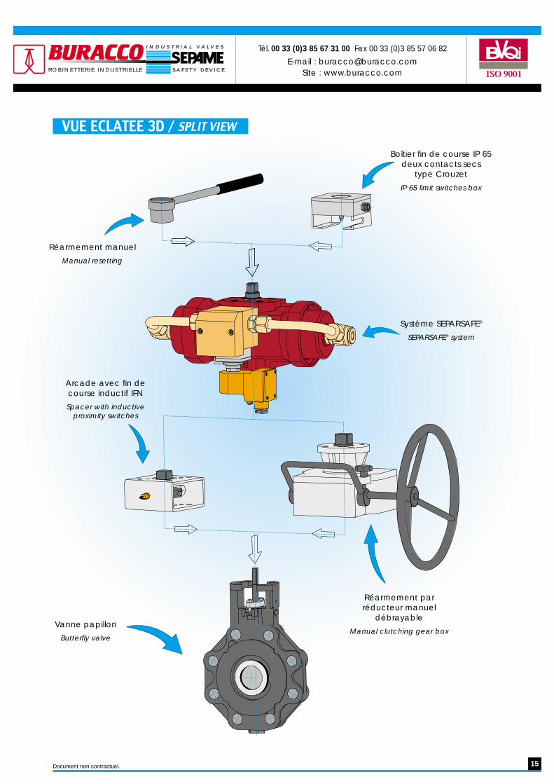
VUE ECLATEE 3D / SPLIT VIEW
Réarmement manuel
Manual resetting
Arcade avec fin decourse inductif IFN
Spacer with inductiveproximity switches
Vanne papillon
Butterfly valve
Boîtier fin de course IP 65deux contacts secs
type Crouzet
IP 65 limit switches box
Système SEPARSAFE®
SEPARSAFE® system
Réarmement parréducteur manuel
débrayable
Manual clutching gear box
Document non contractuel.

robinetterie industrielle
SERIE 2000
ROBINETTERIE INDUSTRIELLE
Robinets à papillonRevêtu plastomère
Plastomere lined butterfly valves
robinetterie industrielle
Doub le excent r ic but te r f l y va lves
SERIE 5000
ROBINETTERIE INDUSTRIELLE
Robinetsà papillon excentré
ISO 9001
Tr ip le o ff se t bu t te r f l y va lves
Robinets à opercule rotatif triple excentration
Matériel conforme à la directive
PED - 97/23/CE
SERIE 3EHigh Performance
Tél. 00 33 (0)3 85 67 31 00Fax 00 33 (0)3 85 57 06 82
E-mail : [email protected] : www.buracco.comR O B I N E T T E R I E I N D U S T R I E L L ER O B I N E T T E R I E I N D U S T R I E L L E
I N D U S T R I A LI N D U S T R I A L V V A LA L V E SV E S
S A F E T Y D E V I C ES A F E T Y D E V I C E
Version ATEX conforme à la directive
94/9/CE, disponible sur demande.
ATEX version according to directive 94/9/CE,
available on request.
R O B I N E T T E R I E I N D U S T R I E L L ER O B I N E T T E R I E I N D U S T R I E L L E
I N D U S T R I A LI N D U S T R I A L V V A LA L V E SV E S
S A F E T Y D E V I C ES A F E T Y D E V I C E
Tél. 00 33 (0)3 85 67 31 00 - Fax 00 33 (0)3 85 57 06 82
E-mail : [email protected] : www.buracco.com
Tél. 00 33 (0)3 85 67 31 00 Fax 00 33 (0)3 85 57 06 82
E-mail : [email protected] : www.buracco.comR O B I N E T T E R I E I N D U S T R I E L L ER O B I N E T T E R I E I N D U S T R I E L L E
I N D U S T R I A LI N D U S T R I A L V V A LA L V E SV E S
S A F E T Y D E V I C ES A F E T Y D E V I C E
But te r f l y va lvesRobinets à papillon
Matériel conforme à la directive
PED - 97/23/CE
SERIE 600 - 900HVAC - INDUSTRY
Tél. 03 85 67 31 00Fax 03 85 57 06 82
E-mail : [email protected] O B I N E T T E R I E I N D U S T R I E L L ER O B I N E T T E R I E I N D U S T R I E L L E
I N D U S T R I A LI N D U S T R I A L V V A LA L V E SV E S
S A F E T Y D E V I C ES A F E T Y D E V I C E
Retrouvez toutes les informations et notices techniques sur notre site web www.buracco.com
Ou communiquez avec nous par e-mail [email protected]