Embed Size (px)
Citation preview

Recover, Recycle, Recharge Machine for R-134a A/C Systems
Operating Manual
Models: 34788NI, 34788NI-H,34788NI-230
1
Table of Contents
Safety Precautions . . . . . . . . . . . . . . . . . . . . . . . 2Explanation of Safety Signal Words . . . . . . . . . . . . . . . 2Explanation of Safety Decals. . . . . . . . . . . . . . . . . . . . . 2Protective Devices . . . . . . . . . . . . . . . . . . . . . . . . . . . . . 4Refrigerant Tank Test . . . . . . . . . . . . . . . . . . . . . . . . . . . 4
Introduction . . . . . . . . . . . . . . . . . . . . . . . . . . . . . 5Technical Specifications . . . . . . . . . . . . . . . . . . . . . . . . 5Features . . . . . . . . . . . . . . . . . . . . . . . . . . . . . . . . . . . . 6Control Panel Functions . . . . . . . . . . . . . . . . . . . . . . . . 8Icon Legend . . . . . . . . . . . . . . . . . . . . . . . . . . . . . . . . . . 9Setup Menu Functions. . . . . . . . . . . . . . . . . . . . . . . . . 10
Initial Setup . . . . . . . . . . . . . . . . . . . . . . . . . . . . 11Unpack the Machine . . . . . . . . . . . . . . . . . . . . . . . . . . .11Unpack the Accessory Kit . . . . . . . . . . . . . . . . . . . . . . .11Power Up the Machine . . . . . . . . . . . . . . . . . . . . . . . . .11Select Language . . . . . . . . . . . . . . . . . . . . . . . . . . . . . 12Select Units . . . . . . . . . . . . . . . . . . . . . . . . . . . . . . . . . 12Set Date and Time . . . . . . . . . . . . . . . . . . . . . . . . . . . . 12Edit Print Header . . . . . . . . . . . . . . . . . . . . . . . . . . . . . 12Service Vacuum . . . . . . . . . . . . . . . . . . . . . . . . . . . . . . 13Select Oil Viscosity . . . . . . . . . . . . . . . . . . . . . . . . . 13Adjust Background Fill Target . . . . . . . . . . . . . . . . . . . 13Tank Fill . . . . . . . . . . . . . . . . . . . . . . . . . . . . . . . . . . . . 13Unit Activation . . . . . . . . . . . . . . . . . . . . . . . . . . . . . . . 15
Operating Instructions . . . . . . . . . . . . . . . . . . . 16Enter Service Data . . . . . . . . . . . . . . . . . . . . . . . . . . . 16Recover Refrigerant from a Vehicle. . . . . . . . . . . . . . . 17Evacuate the Vehicle A/C System . . . . . . . . . . . . . . . . 18Flushing the Hoses . . . . . . . . . . . . . . . . . . . . . . . . . . . 19Recharge the Vehicle A/C System. . . . . . . . . . . . . . . . 20Automatic Function . . . . . . . . . . . . . . . . . . . . . . . . . . . 22System Flush . . . . . . . . . . . . . . . . . . . . . . . . . . . . . . . . 23
Maintenance . . . . . . . . . . . . . . . . . . . . . . . . . . . . 25Maintenance Schedule . . . . . . . . . . . . . . . . . . . . . . . . 25Electrical Protection . . . . . . . . . . . . . . . . . . . . . . . . . . . 26Load Language . . . . . . . . . . . . . . . . . . . . . . . . . . . . . . 26Adjust Background Fill Target . . . . . . . . . . . . . . . . . . . 27Tank Fill . . . . . . . . . . . . . . . . . . . . . . . . . . . . . . . . . . . . 27Filter Maintenance . . . . . . . . . . . . . . . . . . . . . . . . . . . . 28
Check Remaining Filter Capacity . . . . . . . . . . . . . . . 28Replace the Filter . . . . . . . . . . . . . . . . . . . . . . . . . . . 29
Calibration Check . . . . . . . . . . . . . . . . . . . . . . . . . . . . 30Change Vacuum Pump Oil . . . . . . . . . . . . . . . . . . . . . 31Leak Check . . . . . . . . . . . . . . . . . . . . . . . . . . . . . . . . . 32Select Oil Viscosity . . . . . . . . . . . . . . . . . . . . . . . . . . . 33Edit Print Header . . . . . . . . . . . . . . . . . . . . . . . . . . . . . 33Replace Printer Paper . . . . . . . . . . . . . . . . . . . . . . . . . 33Install a Printer. . . . . . . . . . . . . . . . . . . . . . . . . . . . . . . 34
A/C Service Function . . . . . . . . . . . . . . . . . . . . 35Replacement Parts . . . . . . . . . . . . . . . . . . . . . . . . . . . 35Glossary . . . . . . . . . . . . . . . . . . . . . . . . . . . . . . . . . . . 35
Troubleshooting . . . . . . . . . . . . . . . . . . . . . . . . 36Storage and Transportation of Equipment . . . 39Storage . . . . . . . . . . . . . . . . . . . . . . . . . . . . . . . . . . . . 39Transportation of Equipment . . . . . . . . . . . . . . . . . . . . 39
Disposal of Equipment . . . . . . . . . . . . . . . . . . . 40Disposal of Recycled Materials . . . . . . . . . . . . . . . . . . 40Disposal of the Machine . . . . . . . . . . . . . . . . . . . . . . . 40Disposal of Batteries . . . . . . . . . . . . . . . . . . . . . . . . . . 40

2
Safety Precautions
Explanation of Safety Signal Words Used in this ManualThe safety signal word designates the degree, or level, of hazard seriousness.
DANGER: Indicates an imminently hazardous situation which, if not avoided, will result in death or serious injury.
WARNING: Indicates a potentially hazardous situation which, if not avoided, could result in death or serious injury.
CAUTION: Indicates a potentially hazardous situation which, if not avoided, could result in minor or moderate injury.CAUTION: Used without the safety alert symbol indicates a potentially hazardous situation which, if not avoided, could result in property damage.These safety messages cover situations Robinair is aware of. Robinair cannot know, evaluate, or advise as to all possible hazards. The user must verify that conditions and procedures do not jeopardize personal safety.
Explanation of Safety Decals Used on the Machine
Carefully read the instructions.
Do not use in open air in case of rain or high humidity.
Wear gloves.
Wear protection goggles.
Alternating voltage.
Grounding protection.
Electrical shock hazard.
3
Safety Precautions
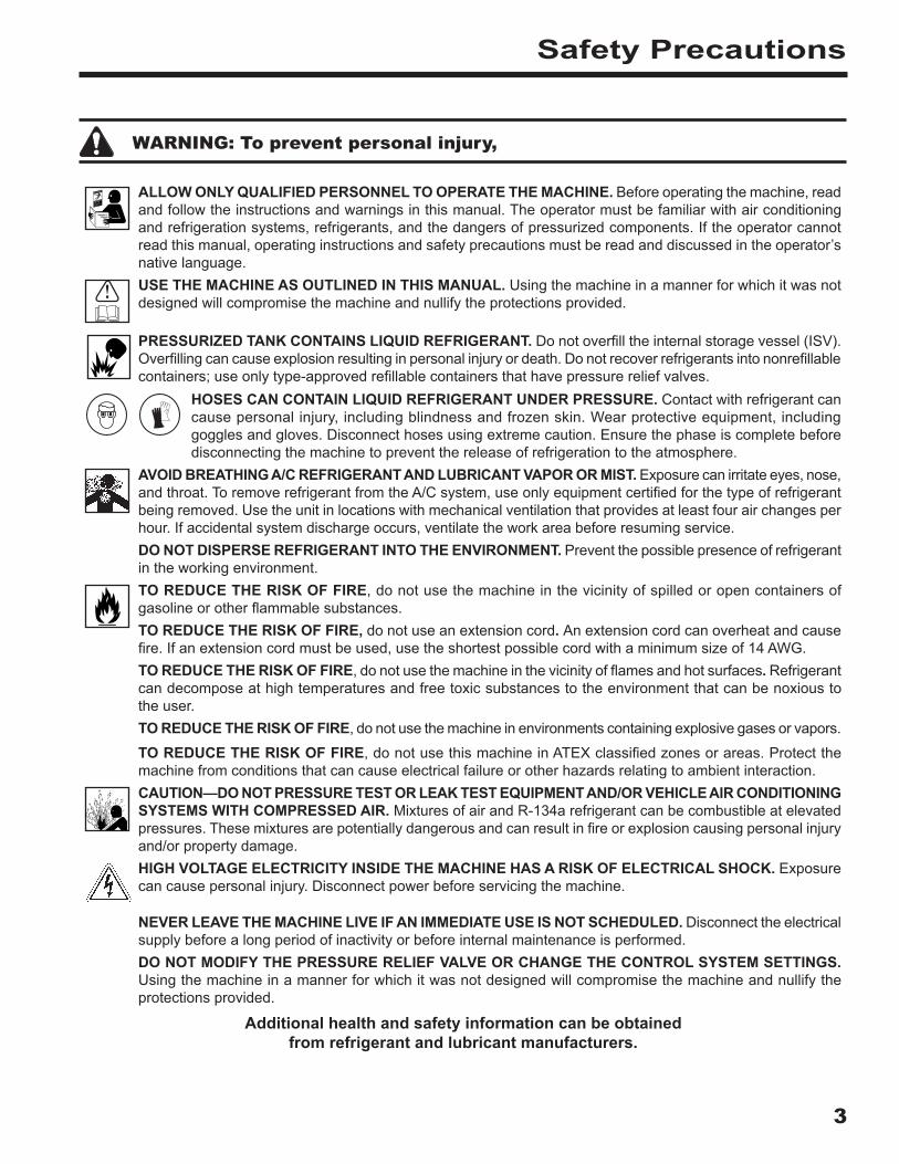
WARNING: To prevent personal injury,
ALLOW ONLY QUALIFIED PERSONNEL TO OPERATE THE MACHINE . Before operating the machine, read and follow the instructions and warnings in this manual. The operator must be familiar with air conditioning and refrigeration systems, refrigerants, and the dangers of pressurized components. If the operator cannot read this manual, operating instructions and safety precautions must be read and discussed in the operator’s native language.USE THE MACHINE AS OUTLINED IN THIS MANUAL . Using the machine in a manner for which it was not designed will compromise the machine and nullify the protections provided.
PRESSURIZED TANK CONTAINS LIQUID REFRIGERANT . Do not overfill the internal storage vessel (ISV). Overfilling can cause explosion resulting in personal injury or death. Do not recover refrigerants into nonrefillable containers; use only type-approved refillable containers that have pressure relief valves.
HOSES CAN CONTAIN LIQUID REFRIGERANT UNDER PRESSURE . Contact with refrigerant can cause personal injury, including blindness and frozen skin. Wear protective equipment, including goggles and gloves. Disconnect hoses using extreme caution. Ensure the phase is complete before disconnecting the machine to prevent the release of refrigeration to the atmosphere.
AVOID BREATHING A/C REFRIGERANT AND LUBRICANT VAPOR OR MIST . Exposure can irritate eyes, nose, and throat. To remove refrigerant from the A/C system, use only equipment certified for the type of refrigerant being removed. Use the unit in locations with mechanical ventilation that provides at least four air changes per hour. If accidental system discharge occurs, ventilate the work area before resuming service.DO NOT DISPERSE REFRIGERANT INTO THE ENVIRONMENT . Prevent the possible presence of refrigerant in the working environment.TO REDUCE THE RISK OF FIRE, do not use the machine in the vicinity of spilled or open containers of gasoline or other flammable substances.TO REDUCE THE RISK OF FIRE, do not use an extension cord . An extension cord can overheat and cause fire. If an extension cord must be used, use the shortest possible cord with a minimum size of 14 AWG.TO REDUCE THE RISK OF FIRE, do not use the machine in the vicinity of flames and hot surfaces . Refrigerant can decompose at high temperatures and free toxic substances to the environment that can be noxious to the user.TO REDUCE THE RISK OF FIRE, do not use the machine in environments containing explosive gases or vapors.
TO REDUCE THE RISK OF FIRE, do not use this machine in ATEX classified zones or areas. Protect the machine from conditions that can cause electrical failure or other hazards relating to ambient interaction.CAUTION—DO NOT PRESSURE TEST OR LEAK TEST EQUIPMENT AND/OR VEHICLE AIR CONDITIONING SYSTEMS WITH COMPRESSED AIR . Mixtures of air and R-134a refrigerant can be combustible at elevated pressures. These mixtures are potentially dangerous and can result in fire or explosion causing personal injury and/or property damage.HIGH VOLTAGE ELECTRICITY INSIDE THE MACHINE HAS A RISK OF ELECTRICAL SHOCK . Exposure can cause personal injury. Disconnect power before servicing the machine.
NEVER LEAVE THE MACHINE LIVE IF AN IMMEDIATE USE IS NOT SCHEDULED . Disconnect the electrical supply before a long period of inactivity or before internal maintenance is performed.DO NOT MODIFY THE PRESSURE RELIEF VALVE OR CHANGE THE CONTROL SYSTEM SETTINGS . Using the machine in a manner for which it was not designed will compromise the machine and nullify the protections provided.
Additional health and safety information can be obtained from refrigerant and lubricant manufacturers .

4
CAUTION : To prevent equipment damage,
Safety Precautions
TO PREVENT CROSS-CONTAMINATION, USE THIS MACHINE WITH R-134A REFRIGERANT ONLY . The machine is equipped with special connectors to recover, recycle, and recharge only R-134a refrigerant. Do not attempt to adapt the machine for another refrigerant. Do not mix refrigerant types through a system or in the same container; mixing of refrigerants will cause severe damage to the machine and the vehicle air conditioning system.DO NOT USE THIS MACHINE IN DIRECT SUNLIGHT . Position the machine far from heat sources, such as direct sunlight, which can cause excessive temperatures. The use of this machine under normal environmental conditions (10°C to 50°C) keeps pressures under reasonable limits.DO NOT USE THIS MACHINE OUTDOORS DURING RAIN OR HIGH HUMIDITY . Protect the machine from conditions that can cause electrical failure or other hazards relating to ambient interaction.DO NOT USE THIS MACHINE IN AREAS WHERE THERE IS A RISK OF EXPLOSION .SET UP THE MACHINE ON AN EVEN SURFACE AND UNDER SUFFICIENT LIGHTING . LOCK THE FRONT WHEELS, AND DO NOT SUBJECT THE MACHINE TO VIBRATION .TO AVOID CHEMICAL INCOMPATIBILITIES WITH THE INTERNAL COMPONENTS OF THE MACHINE, USE ONLY OILS APPROVED BY THE VEHICLE MANUFACTURER . Problems resulting from the use of non-approved oils will void the warranty.
Additional health and safety information can be obtained from refrigerant and lubricant manufacturers .
Protective DevicesThe machine is equipped with the following protective devices:• Over pressure valves.• A maximum pressure switch stops the compressor when excessive pressure is sensed.
WARNING: Tampering with these protective devices could result in serious injury .
Refrigerant Tank TestOfficial records and recurring tests necessary for pressurized instruments are governed by laws and/or national regulations dependent upon the country where the refrigerant tank is used. The system manager is responsible for compliance with laws, regulations, and technical rules. During normal service, refrigerant tanks do not need maintenance. Refer to the Maintenance section of this manual for more information.

5
Introduction
This machine is used on R-134a equipped vehicles and is designed to be compatible with existing service equipment and standard service procedures. This machine is a single-pass system (i.e. refrigerant flows through a filter once) that meets specifications for recycled refrigerant. Follow recommended service procedures for the containment of R-134a.Note: Refrigerant systems require special oils. Refer to the A/C system manufacturer’s service manual for oil specifications.
Technical Specifications
Dimensions . . . . . . . . . . . . . . . . .107 cm x 61 cm x 76 cmDisplay . . . . . . . . . . .5 × 9 cm (4.3-in. diag) graphical LCDFilter . . . . . . . . . . . . . . . . . . . . . . . . . . . . . . . 68 kg (150 lb)Humidity . . . . . . . 32.2°C (90°F), 80% RH non-condensingManometer . . . . . . . . . . . . . . . . . . . . . . Ø 100 mm (3.9 in.)Maximum Pressure . . . . . . . . . . . . . . . . . 27 bar (390 PSI)Noise . . . . . . . . . . . . . . . . . . . . . . . . . . . . . . . . . <70 dB(A)Nominal Voltage
34788NI, 34788NI-H . . . . . . . . . . . . . . . . . .115V, 60 Hz34788NI-230 . . . . . . . . . . . . . . . . . . . . . 230V, 50/60 Hz
Oil Bottle Capacity. . . . . . . . . . . . . . . . . . . .355 ml (12 oz)Operating Temperature . . . 10°C to 50°C (50°F to 122°F)Power Consumption . . . . . . . . . . . . . . . . . . . . . . 1380 VAVacuum Pump Free-Air Displacement . . . . . . . . . . . . . . . . . . . . . . .1.5 CFM (42 L/m) @ 60 Hz . . . . . . . . . . . . . . . . . . . . . .1.25 CFM (35 L/m) @ 50 HzService Hoses . . . . . . . . . . . . . . . . . .250 cm / SAE J2196Tank Capacity . . . . . . . . . . . . . . . . . . . . . . . . 10 kg (22 lb)Weight . . . . . . . . . . . . . . . . . . . . . . . . . . . . . 73 kg (161 lb)

6
Introduction
Features
5
9
3
2
1
6
7
4
8
10
11
12
14
13
7
Introduction
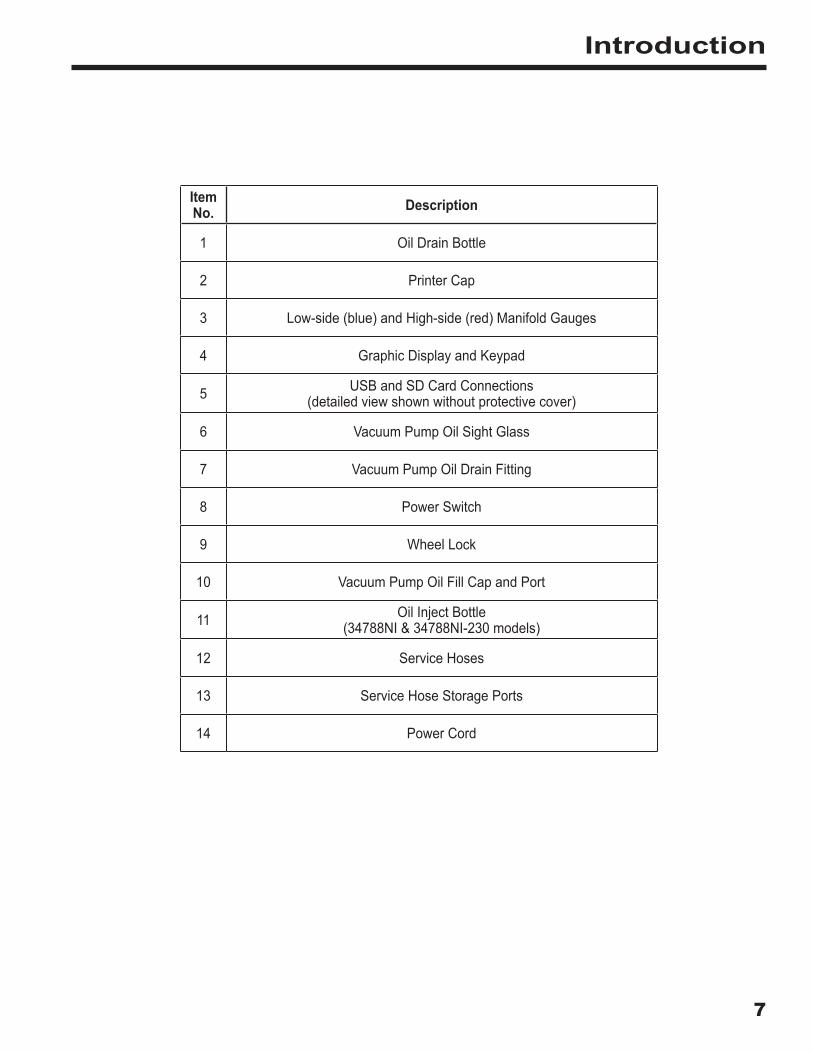
ItemNo . Description
1 Oil Drain Bottle
2 Printer Cap
3 Low-side (blue) and High-side (red) Manifold Gauges
4 Graphic Display and Keypad
5 USB and SD Card Connections(detailed view shown without protective cover)
6 Vacuum Pump Oil Sight Glass
7 Vacuum Pump Oil Drain Fitting
8 Power Switch
9 Wheel Lock
10 Vacuum Pump Oil Fill Cap and Port
11 Oil Inject Bottle (34788NI & 34788NI-230 models)
12 Service Hoses
13 Service Hose Storage Ports
14 Power Cord
8
Introduction
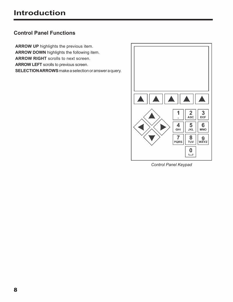
Control Panel Functions
ARROW UP highlights the previous item.ARROW DOWN highlights the following item.ARROW RIGHT scrolls to next screen.ARROW LEFT scrolls to previous screen.SELECTION ARROWS make a selection or answer a query.
Control Panel Keypad

9
Introduction
Icon Legend
AUTOMATIC ICON Pressing the key under this icon will enter the automatic refrigerant recovery, vacuum, and charge process.
RECOVER ICON Pressing the key under this icon will enter the refrigerant recovery process.
VACUUM ICON Pressing the key under this icon will enter the system vacuum process.
CHARGE ICON Pressing the key under this icon will enter the refrigerant charge process.
NEXT/FORWARD ICON Pressing the key under this icon will proceed to additional menu selection options, or proceed to an additional step in a function or process.
BACK ICON Pressing the key under this icon will return to previously seen menu selection options, or return to the previous screen within a function or process.
HELP ICON Pressing the key under this icon will provide help and information corresponding to the current screen and/or function being viewed or performed.
DATABASE ICON Pressing the key under this icon will enter the vehicle database retrieval process.
SETUP MENU ICON Pressing the key under this icon will enter the Setup Menu.
YES/ACCEPT ICON Pressing the key under this icon will ac-cept any choices made on the current screen and proceed to the next step of the function.
NO/CLOSE ICON Pressing the key under this icon will reject any choices made on the current screen and return to the previous step of the function or the Main Menu.
RETRY ICON Pressing the key under this icon will retry the current process or function.
CHARGE PATH SELECTION ICON Pressing the key under this icon will toggle the desired path of refrigerant charge between high side, low side, and both side.
OIL INJECT BOTTLE SELECTION ICON Pressing the key under this icon will toggle which bottle will be utilized to inject oil during the subsequent charge. (Applicable only on machines with more than one oil inject bottle.)
ON/OFF ICON Pressing the key under this icon will toggle the highlighted function on or off as desired.
BACKSPACE ICON Pressing the key under this icon will delete a text character to the left of the current selection.
PAUSE ICON Pressing the key under this icon will pause the current process.
RESUME ICON Pressing the key under this icon will resume a process that has been paused.
PRINT ICON Pressing the key under this icon will print a summary corresponding to the current completed process.
DELETE ICON Pressing the key under this icon will delete a selected entry from the memory of the machine.
CHANGE UNITS ICONS Pressing the key under one of these icons will toggle the unit of measurement for the current entry field.

10
Introduction
Setup Menu FunctionsAccess the following functions by pressing the Menu key and selecting Setup.
Select UnitsProgram the machine to display units of measure in kilograms or pounds. The default display is kilograms. Date and TimeProgram the machine for current date and time. System FlushProvides a method of removing oil by forcing liquid refrigerant through an A/C system or components of an A/C system. After flushing, the refrigerant is recovered by the machine and filtered by the recycling circuit.System InformationDisplays the revision level of the software in the machine.Tank FillUse this Setup Menu item to transfer refrigerant from a source tank to the ISV. The tank fill value may be adjusted up or down to suit the user’s needs. Refer to Tank Fill in the Maintenance section. Unit ActivationFailure to register and activate the machine within 30 days of initial startup will cause the machine to lock out and no longer function. Select this Setup Menu item and follow the prompts before the trial period expires. View Service DataDisplays vehicle information that was entered into the Enter Service Data screen. Vehicles are displayed by date of service and VIN number. The database stores 25 VIN entries.Hose EqualizeUse this Setup Menu item to recover refrigerant from the service hoses back into the vehicle A/C system. This item is useful after performing diagnostics which do not require the need to recover the A/C system into the RRR machine. The user will be prompted to connect the low side service hose to the appropriate port and to start the vehicle’s A/C system on max.
Calibration CheckUse to verify internal scale calibration. Refer to Calibration Check in the Maintenance section of this user manual.Edit Print HeaderPrograms information that will appear on the printout each time a print function is used. Filter MaintenanceThe filter removes acid, particulates, and moisture from the refrigerant. To meet requirements, it is mandatory to replace the filter after 68 kg (150 lb) of refrigerant has been filtered. This menu item displays the filter capacity remaining until the machine locks down and no longer functions. Refer to Filter Maintenance in the Maintenance section.Flush HosesFlushes residual oil from the machine’s service hoses to prepare for service of next vehicle.Production MenuFor Robinair production use only.Pump MaintenanceDisplays the amount of time remaining until the next vacuum pump oil change is needed. For maximum vacuum pump performance, change vacuum pump oil every time the filter is replaced. Refer to the Change Vacuum Pump Oil in the Maintenance section.Refrigerant ManagementDisplays the amount of refrigerant recovered, charged, and replenished (for the life of the machine), and filtered since the last filter change.Select LanguageSelect a language for screen prompts. English is the default language.Service MenuFor Robinair service center use only.

11
Initial Setup
WARNING: To prevent personal injury while working with refrigerant, read and follow the instructions and warnings in this manual, and wear protective equipment such as goggles and gloves .
Unpack the Machine1. Remove the bandings from the box.2. Remove the top carton infold, the molded pulp tray, and
the angle boards.3. Remove the sleeve from the bottom carton infold.4. Gently roll the unit forward and off the pallet, avoiding
any sudden shocks to the machine.
Unpack the Accessory KitUnpack the accessory kit from the box, and remove the plastic packaging.
Calibration Check Weight
533 g (1.18 lb)
Pouch containing the user manual, warranty card to be filled out and mailed, Safety Data Sheets (SDSs), and
service center list.
Power Up the Machine1. Unwind the power cord from the handle, and plug it into
a correct voltage, grounded outlet.2. Position the machine so the plug and the power switch
are of easy access for the operator. Verify the fan ventson the rear of the machine are not obstructed.
3. Lock the front wheels.4. Toggle the power switch on the control panel to turn the
machine ON.The machine launches into the initial Setup mode.

12
Initial Setup
Select LanguageThe operator selects the language for the screen prompt displays. English is the default language. 1. Use the UP or DOWN arrow key to toggle through the
available languages one line at a time.2. Select to set the selected language.Note: To update an existing language or to add a new language, refer to Load Language in the Maintenance section of this manual.
Select UnitsThe operator sets the display for units of measure. Metric is the default.3. Use the ARROW UP or ARROW DOWN key to toggle
Imperial or Metric units.4. Select to choose the displayed unit of measure.
Set Date and TimeUse the arrow keys to move the cursor. Use the keypad to modify the information displayed.5. Use the ARROW UP and ARROW DOWN keys to select
which item to change: day, month, year, or time. Select to toggle between AM and PM.
6. Use the multi-tap interface on the numeric keypad tomodify the information.
7. Select to save.
Edit Print HeaderThis machine has the capability to store recovery, vacuum, charge, and flush information for up to 25 vehicles. The information loaded into Edit Print Header will appear on each printout.1. Enter text by using the arrows and the multi-tap interface
on the numeric keypad:• ARROW LEFT and key act as backspace key.• ARROW RIGHT moves the cursor to the right.• 0 (ZERO) acts as a spacebar when pressed twice.• ARROW UP and DOWN navigate between the rows.
2. Select to save/exit the function; select to return to the previous header without saving data.

13
Initial Setup
Service VacuumAt this point the machine clears its internal plumbing before proceeding with setup. 1. Check the vacuum pump oil level sight glass and verify
the oil level is at the center of the sight glass.2. When prompted, connect the service hoses from the
machine to their storage ports as shown in Figure 1.Select to continue.
3. The machine enters a 5-minute vacuum and will automaticallyenter the next set-up process when complete.
Select Oil Viscosity (N/A for 34788NI-H)
The oil inject functionality in this machine is automatic and timing based. The viscosity of the oil being injected significantly affects the accuracy.1. Using the arrow keys, highlight your desired PAG oil
viscosity (46, 100, 125, or 150). Once highlighted, select to accept.
2. The unit is now ready to accurately inject the chosen oil.
Adjust Background Fill TargetThis machine possesses a background tank fill feature. An external refrigerant storage vessel can be fluidly connected to the machine (using the black tank fill hose) for a continuous topping off of the internal storage vessel. Drawing from the refrigerant within the connected external storage vessel, the machine will periodically charge the ISV tank to the desired fill target.Using the arrows and the numeric keypad, enter the desired fill target (default amount is 4.54 kg).
Tank FillThis procedure transfers refrigerant from a source tank to the internal storage vessel (ISV) in the machine. The maximum capacity of the ISV is 10 kg (22 lb). Use arrow keys to move the cursor; use the keypad to enter a value.1. The machine displays fields for desired tank fill amount,
charge capacity, and the amount of recoverable refrigerant(recover capacity) within the internal storage vessel. Enterthe desired tank fill amount.Note: Add at least 3.6 kg of refrigerant to ensure enoughis available for charging.
Figure 1
Service Hoses Connected to Storage Ports
Note:Charge Capacity: The amount of refrigerant in the ISV that can be charged into a vehicle A/C system.Recover Capacity: The amount of additional refrigerant that could be recovered into the ISV.
WARNING: To prevent personal injury while working with refrigerant, read and follow the instructions and warnings in this manual, and wear protective equipment such as goggles and gloves .

14
Initial Setup
2. Connect the tank fill (black) hose to the liquid connectoron the source tank.
3. Open the source tank valve.4. Position the source tank in such a way that liquid refrigerant
is supplied to the connection.5. Select to start the tank fill process. The machine begins
filling the internal storage vessel (ISV). Add at least 3.6 kgof refrigerant to ensure enough is available for charging.This process takes 15–20 minutes.
6. The machine stops when the designated amount ofrefrigerant has been transferred to the ISV or when thesource tank is empty. Follow the messages on the display.
7. Close the source tank valve.8. Select to return to the Setup Menu.The machine is ready for operation.Note: • There is no need to calibrate the scale; it is calibrated at
the factory.• After the tank fill process is complete, the display does
not show the same amount as the programmed fill level.The display shows the amount of refrigerant that is available for charging, which is approximately 0.67 kg (1.4 lb) less than the total amount of refrigerant in the tank.

15
Initial Setup
Unit ActivationFailure to register and activate the machine within 30 days of initial startup will cause the machine to lock out and no longer function. 1. Select Unit Activation from the Setup Menu. The
machine displays
XX Days Left on Trial Period to activate unit. Activate Now?
2. Select to start the activation process. The machinedisplays
Product Activation
Personal product code: XXXXXXXXXXX
Enter code: XXXXXXXXXXXX
3. Open a web browser on a personal computer andenter https://register.servicesolutionsportal.com.
4. Enter the user name and password, and log in to thewebsite.Note: If a first-time user, select REGISTER to createa user name and password.
5. On the personal computer, enter the Personal ProductCode of the machine into the Product Activation keybox on the website to receive an activation code.
6. On the machine, enter the activation code into thecorrect field. Note: Enter the code exactly as received.Capitalization is required.
7. Record the activation code on a piece of paper andfile it in a secure place. Select .
8. The machine displays
Activation successful.
Select . The machine has been activated.

16
Operating Instructions
Enter Service DataAfter selecting any service function, information about the vehicle may be entered into and stored in the machine’s database.The machine displays
Enter service data new
1. Select to enter a new record, or scroll to select apreviously serviced vehicle and then select . Thehighlighted selection will be in red. The machine displays
Enter service data VIN: _____________________________ Mileage: _______________________ Make: ___________________________ Model: _________________________
2. Use the arrow keys to move between rows and the multi-tap keypad to enter text.Information entered on this screen is stored by date andvehicle identification number (VIN). The database storesthe latest 25 entries, with the most recent at the top ofthe list.The information will also appear on service summaryprintouts.

17
Recover Refrigerant from a Vehicle1. Empty the oil drain bottle before starting a recovery.
Remove the oil drain bottle from the machine by pullingthe bottle straight down—do not use a twisting or rockingmotion. Reinstall the oil drain bottle. See Figure 2.
2. Connect the high-side (red) and low-side (blue) servicehoses to the vehicle A/C system.
3. Open the coupler valves on the hoses by turning thecollars clockwise.
4. Select RECOVER from the MAIN MENU.5. The machine will enter the service data entry form. Enter
all applicable data and select to continue.The machine begins the recovery process. A clickingnoise indicates the solenoid is opening and closing —this is normal.The machine runs a self-clearing cycle to clear any internalrefrigerant from its internal plumbing.System recovery begins and includes a timed vacuum,deep recovery process.After recovery, the machine will perform an oil drain, whichmay require up to 90 seconds to complete.
6. After the oil drain is complete, a summary is displayedshowing the total amount of refrigerant recovered. Theuser is prompted to “Check Oil Drain Bottle” to noteamount of oil drained. Recovery information can beprinted by selecting on machines equipped with aprinter.
7. Select to return to the Main Menu.Note: The displayed recovered weight can vary dependingon ambient conditions and should not be used as anindicator of scale accuracy.Note: The amount of oil that was removed from the A/Csystem is the amount of new oil that should be chargedinto the A/C system after evacuation is complete.• Use only new oil to replace the oil removed during
the recycling process.• Dispose of used oil according to government
regulations.
Figure 2
Operating Instructions
WARNING: To prevent personal injury while working with refrigerant, read and follow the instructions and warnings in this manual, and wear protective equipment such as goggles and gloves .
Oil Drain Bottle

18
Operating Instructions
Evacuate the Vehicle A/C System1. Connect the service hoses to the vehicle’s service ports.2. Open the service hose coupler valves by turning the
collars clockwise.3. Select VACUUM from the MAIN MENU.4. Select Vacuum Leak Check, if desired, to automatically
perform a 5-minute pressure rise leak check after the vacuum.
5. Select to accept the 10-minute default evacuation time, or enter a desired vacuum time using the number keys.Note: The vacuum process will halt if pressure rises above .35 bar (5 psi). Recover refrigerant before proceeding.The machine pulls a vacuum on the A/C system for the programmed amount of time.Vacuum information can be printed by selecting on machines equipped with a printer.
6. Select to return to the Main Menu.
WARNING: To prevent personal injury while working with refrigerant, read and follow the instructions and warnings in this manual, and wear protective equipment such as goggles and gloves .

19
Operating Instructions
Flushing the HosesIf the next vehicle to be serviced contains a different type of oil than the previous vehicle serviced, it is recommended the service hoses be flushed of residual oil to prevent contamination.1. Select FLUSH HOSES from the SETUP MENU. The
machine displays
Connect service hoses to storage ports and open coupler valves.
2. Connect the service hoses to the machine’s storage port connections as shown in Figure 3.
3. Open the service hose coupler valves by turning the collars clockwise.
4. Select to begin the hose flush process, which runs for three minutes, followed by a recovery.When the hose flushing process is compete, the display reads
FLUSH HOSES Complete
5. Select to return to the Setup Menu.6. Close the coupler valves by turning the collars
counterclockwise.
Figure 3
Storage Port
Connections

20
Recharge the Vehicle A/C System (N/A for 34788NI-H)
1. Connect both service hoses to the vehicle’s service ports.2. Select CHARGE from the MAIN MENU.3. The user will be prompted to enter service data. Select
once complete to continue. The display shows Charge: XX.XXX kg on High Side Oil Amount: XXX ml Min Charge quantity 10g
4. Use the arrow keys and the numeric keypad to enter thedesired charge amount. Select to change units.
5. Using the arrow keys, maneuver to the charge pathselection. High Side is default. To change, selecton the control panel. This will allow the user to togglebetween high, low, and both side charge paths. Thecurrent selection is indicated on the display.
6. Oil can also be injected into the system during thecharge. Use the numeric keypad to enter the desiredoil inject amount. Select to change units. Makesure there is available oil in the oil/dye inject bottlelocated on the rear of the machine and verify thecorrect oil viscosity is selected. See “Select Oil Viscosity(N/A for 34788NI-H)” on page 13.
7. Select to start the charge process. Moving or bumpingthe machine at this point may result in an inaccuratecharge. When the charge cycle approaches the desiredweight value, the machine slows down. It will charge,settle, charge again, settle, etc.
8. When prompted, select to perform hose equalization.Select to perform hose compensation.Note: Hose equalization requires the user to start the vehicle. Hose compensation adds a preset amount of refrigerant to the chart to compensate for service hose volume.
9. When the CHARGE COMPLETE screen appears, itincludes a summary of charge results. The user may select
to print the summary, if a printer is installed. Select to proceed to clear the service hoses.
10. The user will be prompted to close the coupler valves anddisconnect the hoses from the vehicle. Select to recoverany remaining refrigerant from the hoses. Once the hoseclear is complete, the machine will return to the Main Menu.
The vehicle A/C system is now ready for use.
WARNING: To prevent personal injury while working with refrigerant, read and follow the instructions and warnings in this manual, and wear protective equipment such as goggles and gloves .
Note: The charging process differs from vehicle to vehicle. Charge function for vehicles equipped with a single service fitting should be carried out manually. Refer to the vehicle service manual for specific instructions.
CAUTION: If the low-side (blue) or high-side (red) coupler valve is left open during the hose clearing process, the system will pull refrigerant back out of the vehicle .
Operating Instructions

21
Operating Instructions
Recharge the Vehicle A/C System (34788NI-H model)
1. Select CHARGE from the MAIN MENU.The display shows
Is the service being performed on a system with an electric compressor using POE oil?
2. If the system does NOT have an electric compressor withPOE oil, select to continue. If the system has an electriccompressor with POE oil, select to flush all residualoil from the hoses. The user will be prompted to “Connectservice hoses to storage ports and open coupler valves.”See “Figure 3” on page 19. Continuing will begin theprocess of flushing the hoses. Once complete, selectto continue through the Charge process.
3. The user will be prompted to enter service data. Select once complete to continue. The display shows
Charge: XX.XXX kg on High Side
4. Connect both service hoses to the vehicle’s service portsand open coupler valves.
5. Use the arrow keys and the numeric keypad to enter thedesired charge amount. Select to change units.
6. Using the arrow keys, maneuver to the charge pathselection. High Side is default. To change, selecton the control panel. This will allow the user to togglebetween high, low, and both side charge paths. Thecurrent selection is indicated on the display.
7. Select to start the charge process. Moving or bumpingthe machine at this point may result in an inaccuratecharge. When the charge cycle approaches the desiredweight value, the machine slows down. It will charge,settle, charge again, settle, etc.
8. When prompted, select to perform hose equalization.Select to perform hose compensation.Note: Hose equalization requires the user to start the vehicle. Hose compensation adds a preset amount of refrigerant tothe chart to compensate for service hose volume.
9. When the CHARGE COMPLETE screenappears, it includes a summary of chargeresults. The user may select to print thesummary, if a printer is installed. Selectto proceed to clear the service hoses.
10. The user will be prompted to close thecoupler valves and disconnect the hosesfrom the vehicle. Select to recover anyremaining refrigerant from the hoses. Oncethe hose clear is complete, the machine willreturn to the Main Menu.
The vehicle A/C system is now ready for use.
22
Operating Instructions
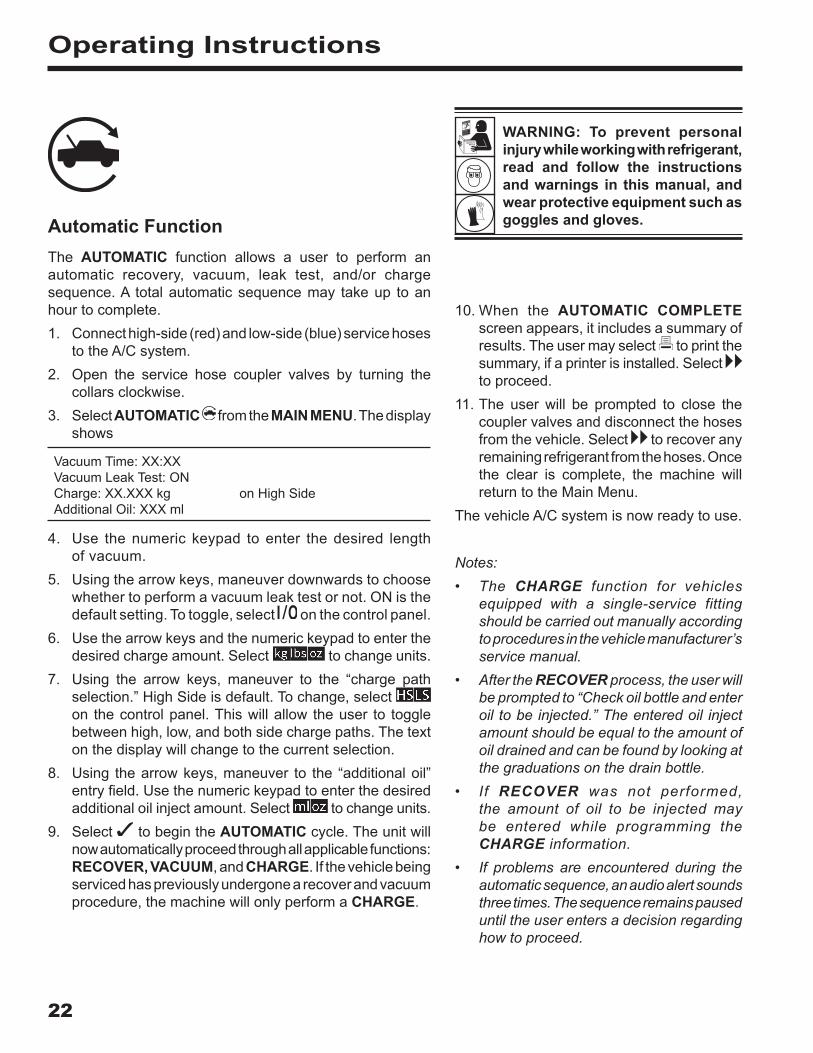
Automatic FunctionThe AUTOMATIC function allows a user to perform an automatic recovery, vacuum, leak test, and/or charge sequence. A total automatic sequence may take up to an hour to complete.1. Connect high-side (red) and low-side (blue) service hoses
to the A/C system.2. Open the service hose coupler valves by turning the
collars clockwise.3. Select AUTOMATIC from the MAIN MENU. The display
shows
Vacuum Time: XX:XX Vacuum Leak Test: ON Charge: XX.XXX kg on High Side Additional Oil: XXX ml
4. Use the numeric keypad to enter the desired lengthof vacuum.
5. Using the arrow keys, maneuver downwards to choosewhether to perform a vacuum leak test or not. ON is thedefault setting. To toggle, select on the control panel.
6. Use the arrow keys and the numeric keypad to enter thedesired charge amount. Select to change units.
7. Using the arrow keys, maneuver to the “charge pathselection.” High Side is default. To change, selecton the control panel. This will allow the user to togglebetween high, low, and both side charge paths. The texton the display will change to the current selection.
8. Using the arrow keys, maneuver to the “additional oil”entry field. Use the numeric keypad to enter the desiredadditional oil inject amount. Select to change units.
9. Select to begin the AUTOMATIC cycle. The unit willnow automatically proceed through all applicable functions:RECOVER, VACUUM, and CHARGE. If the vehicle beingserviced has previously undergone a recover and vacuumprocedure, the machine will only perform a CHARGE.
10. When the AUTOMATIC COMPLETEscreen appears, it includes a summary ofresults. The user may select to print thesummary, if a printer is installed. Selectto proceed.
11. The user will be prompted to close thecoupler valves and disconnect the hosesfrom the vehicle. Select to recover anyremaining refrigerant from the hoses. Oncethe clear is complete, the machine willreturn to the Main Menu.
The vehicle A/C system is now ready to use.
Notes:• The CHARGE function for vehicles
equipped with a single-service fittingshould be carried out manually accordingto procedures in the vehicle manufacturer’s service manual.
• After the RECOVER process, the user will be prompted to “Check oil bottle and enter oil to be injected.” The entered oil injectamount should be equal to the amount ofoil drained and can be found by looking atthe graduations on the drain bottle.
• If RECOVER was not performed,the amount of oil to be injected maybe entered while programming theCHARGE information.
• If problems are encountered during theautomatic sequence, an audio alert sounds three times. The sequence remains paused until the user enters a decision regardinghow to proceed.
WARNING: To prevent personal injury while working with refrigerant, read and follow the instructions and warnings in this manual, and wear protective equipment such as goggles and gloves .
23
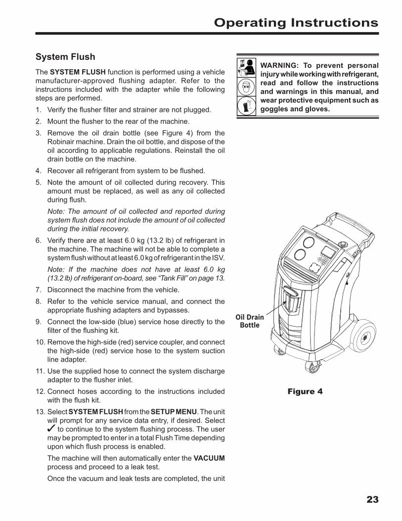
System FlushThe SYSTEM FLUSH function is performed using a vehicle manufacturer-approved flushing adapter. Refer to the instructions included with the adapter while the following steps are performed.1. Verify the flusher filter and strainer are not plugged.2. Mount the flusher to the rear of the machine.3. Remove the oil drain bottle (see Figure 4) from the
Robinair machine. Drain the oil bottle, and dispose of the oil according to applicable regulations. Reinstall the oil drain bottle on the machine.
4. Recover all refrigerant from system to be flushed.5. Note the amount of oil collected during recovery. This
amount must be replaced, as well as any oil collected during flush. Note: The amount of oil collected and reported during system flush does not include the amount of oil collected during the initial recovery.
6. Verify there are at least 6.0 kg (13.2 lb) of refrigerant in the machine. The machine will not be able to complete a system flush without at least 6.0 kg of refrigerant in the ISV.Note: If the machine does not have at least 6.0 kg (13.2 lb) of refrigerant on-board, see “Tank Fill” on page 13.
7. Disconnect the machine from the vehicle.8. Refer to the vehicle service manual, and connect the
appropriate flushing adapters and bypasses.9. Connect the low-side (blue) service hose directly to the
filter of the flushing kit.10. Remove the high-side (red) service coupler, and connect
the high-side (red) service hose to the system suction line adapter.
11. Use the supplied hose to connect the system discharge adapter to the flusher inlet.
12. Connect hoses according to the instructions included with the flush kit.
13. Select SYSTEM FLUSH from the SETUP MENU. The unit will prompt for any service data entry, if desired. Select
to continue to the system flushing process. The user may be prompted to enter in a total Flush Time depending upon which flush process is enabled.The machine will then automatically enter the VACUUM process and proceed to a leak test.Once the vacuum and leak tests are completed, the unit
Operating Instructions
Figure 4
WARNING: To prevent personal injury while working with refrigerant, read and follow the instructions and warnings in this manual, and wear protective equipment such as goggles and gloves .
Oil Drain Bottle

24
Operating Instructions
will enter the actual system flushing process, followed by an oil drain.
14. When the Flush Complete screen appears, it includesa system flush result summary. The user may selectto print the summary, if a printer is installed. Select toreturn to the SETUP MENU.
The vehicle A/C system has been flushed.
WARNING: Do NOT disconnect service couplers during the flushing process. Refrigerant could spray out of the fittings, and exposure may cause personal injury .
CAUTION: The flushing kit has a replaceable filter as well as a debris strainer, both of which can get plugged . At the end of the flush cycle, check the high-side (red) gauge for system pressure, and check the adapter for complete removal of refrigerant .
If pressure exists or refrigerant remains, exit the flushing cycle and enter the recovery mode to recover refrigerant through both the high-side (red) and low-side (blue) hoses. Then service the filters and repeat the flush process.
25
Maintenance Schedule
Maintenance Task Recommended Interval
Change filterAfter 68 kg (150 lb) of refrigerant has been filtered. Refer to Filter Maintenance in the Maintenance section of this manual.
Change vacuum pump oilWhen the filter is replaced. Refer to Change Vacuum Pump Oil in the Maintenance section of this manual.
Check casters and wheels for ease of operation Monthly.
Check internal scale calibration Monthly. Refer to Calibration Check in the Maintenance section of this manual.
Check machine for leaks
Monthly. Check hoses and connections for leakage. Disconnect power, remove the shroud, and use an electronic leak detector to check fittings.
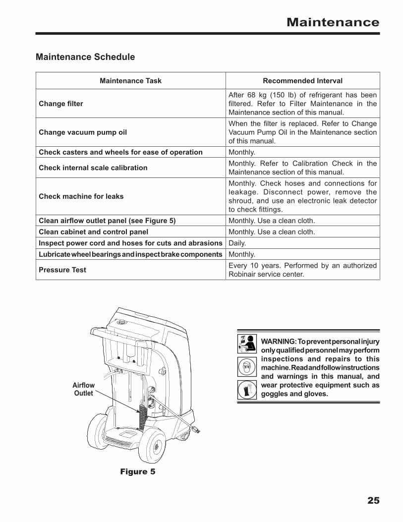
Clean airflow outlet panel (see Figure 5) Monthly. Use a clean cloth.Clean cabinet and control panel Monthly. Use a clean cloth.Inspect power cord and hoses for cuts and abrasions Daily.Lubricate wheel bearings and inspect brake components Monthly.
Pressure Test Every 10 years. Performed by an authorized Robinair service center.
Maintenance
Figure 5
Airflow Outlet
WARNING: To prevent personal injury only qualified personnel may perform inspections and repairs to this machine . Read and follow instructions and warnings in this manual, and wear protective equipment such as goggles and gloves .
26
Maintenance
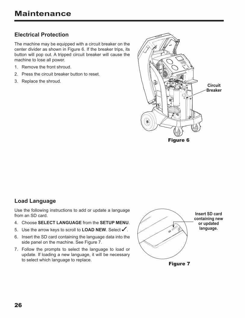
Electrical ProtectionThe machine may be equipped with a circuit breaker on the center divider as shown in Figure 6. If the breaker trips, its button will pop out. A tripped circuit breaker will cause the machine to lose all power.1. Remove the front shroud.2. Press the circuit breaker button to reset.3. Replace the shroud.
Insert SD card containing new
or updated language .
Load LanguageUse the following instructions to add or update a language from an SD card.4. Choose SELECT LANGUAGE from the SETUP MENU.5. Use the arrow keys to scroll to LOAD NEW. Select .6. Insert the SD card containing the language data into the
side panel on the machine. See Figure 7.7. Follow the prompts to select the language to load or
update. If loading a new language, it will be necessaryto select which language to replace.
Circuit Breaker
Figure 6
Figure 7

27
Maintenance
Adjust Background Fill TargetThis machine possesses a background tank fill feature. An external refrigerant storage vessel can be fluidly connected to the machine (using the black tank fill hose) for a continuous topping off of the internal storage vessel. Drawing from the refrigerant within the connected external storage vessel, the machine will periodically charge the ISV tank to the desired fill target.1. Select ADJUST BACKGROUND FILL TARGET in the
SETUP MENU.2. Using the arrows and the numeric keypad, enter the
desired fill target. Select to save the new value andexit. Select to exit and continue to use the previouslyentered amount.
Tank FillThis menu item is used to transfer refrigerant from a source tank to the ISV. The maximum capacity of the internal storage vessel (ISV) is 10 kg. Use the arrow keys to move the cursor; use the keypad to enter a value.Note: Add at least 3.6 kg of refrigerant to ensure sufficient refrigerant is available for charging.1. Connect the tank fill (black) hose to the liquid connector
on a full source tank.2. Position the source tank in such a way that liquid refrigerant
is supplied to the connection. Open the source tank valve.3. Select TANK FILL from the SETUP MENU. The machine
displays
Tank Fill Fill Amount: XX.XYY Charge Capacity: XX.XXYY Recover Capacity: XX.XXYY
4. Enter the quantity to recover, and select .Note: Add at least 3.6 kg of refrigerant to ensure sufficient refrigerant is available for charging.5. The machine begins filling the ISV and automatically
stops when the preset tank fill level is reached. To stopthe tank fill before the preset level is reached, select .An option to exit will appear on the display.
6. Once complete, remove the hose from the source tank.
WARNING: To prevent personal injury while working with refrigerant, read and follow the instructions and warnings in this manual, and wear protective equipment such as goggles and gloves .
28
Maintenance
Filter MaintenanceThe filter is designed to trap acid and particulates, and to remove moisture from refrigerant. To meet the mandate for adequate moisture and contaminant removal, the filter must be replaced after 68 kg (150 lb) of refrigerant has been filtered.The machine gives a warning when 57 kg (125 lb) of the filter capacity has been used; the machine locks down when the 68 kg (150 lb) filter capacity has been reached and will no longer function.
Check Remaining Filter Capacity
1. Select FILTER MAINTENANCE from the SETUP MENUor when the machine prompts. The machine displays
Remaining Filter Capacity: XXX.XO kg Replace filter now?
The machine displays the amount of filter capacity remaining until the machine locks down.
2. Select to change the filter; select to resume usingthe machine.
WARNING: The components in the machine are under high pressure . To prevent personal injury, change the filter only when the machine prompts.
WARNING: To prevent personal injury while working with refrigerant, read and follow the instructions and warnings in this manual, and wear protective equipment such as goggles and gloves .

29
Maintenance
Replace the Filter
1. If was selected to change the filter, the machine promptsfor the new filter code to be entered.
Enter new filter serial number
Use the keypad to enter the serial number that appears on the new filter, and select to continue.Note: If “Invalid serial number” is displayed, the serial number has been incorrectly entered, or the filter has already been used in this machine.
2. The machine clears the existing filter and displays
Serial number accepted. Turn power off and replace filter.
Turn off the machine. Remove the oil bottle. Remove the four screws holding the shroud. See Figure 8.
3. Hang the shroud on the back of the machine as shownin Figure 9.
4. Remove the filter by turning it counterclockwise (as viewedfrom the bottom of the filter).
5. Look at the new filter. Verify both o-rings are lubricatedand correctly located in the grooves.
6. Install the new filter by threading it clockwise into place.Verify the filter is positioned correctly as shown in Figure9. Tighten the filter to 20 Nm.
7. Power the machine on. The Change Vacuum Pump Oiloperation will begin, and the screen will display
Warming oil for drain XX:XX
See “Change Vacuum Pump Oil” on page 31 for more information.The machine will then begin the Leak Check operation. See “Leak Check” on page 32 for more information.
Caution: To prevent equipment damage, use only authentic Robinair No. 34724 filters in this machine. All performance tests and claims are based on using this specific filter.
Figure 8
Figure 9
Remove the four screws holding the shroud.
Hang Shroud Here
Filter

30
Maintenance
Calibration CheckThis function is used to ensure the machine’s internal scale is always calibrated. During this test, use only the calibration weight that is provided with the machine.1. Refer to Figure 10, and verify the magnet on the bottom
of the machine is clean.2. Select CALIBRATION CHECK from the SETUP MENU.
The machine displays
Place calibration weight onto the magnet located on the bottom of the machine.
3. Attach the calibration weight to the magnet on the bottomof the machine. Select to continue.
4. The machine displays
Remove calibration weight from the magnet located on the bottom of the machine.
Remove the calibration weight from the magnet. Select to continue.
• If the display shows
Calibration check passed
the scale is in calibration. Select to return to the Setup Menu.• If the display shows
Calibration check failed. Retry?
the scale is out of calibration. To retry, select . If calibration continues to fail, contact an authorized Robinair service center for assistance.
Magnet
Figure 10

31
Maintenance
Change Vacuum Pump Oil1. Select PUMP MAINTENANCE from the SETUP MENU or
when prompted. The display shows how long the vacuumpump has operated since the last oil change.
Remaining oil life: XXX:XX (hhh:mm) Change oil now?
2. Select to change vacuum pump oil. If the machinedisplays
Warming oil for drain XX:XX
allow the vacuum pump to run for two minutes to warm up the oil. If the oil is already warm, the display shows
Drain used oil from pump and replace with 150 ml of new oil Remove fill cap to speed draining of oil
3 . Slowly open the oil fill cap to verify there is no pressure in the machine. Then carefully remove the cap. See Figure 11.
4. Remove the oil drain fitting cap and drain the oil into asuitable container for disposal. Replace the cap and closetightly. Select to continue.
5. The machine displays
Fill vacuum pump to the center of the sight glass Reinstall fill cap
Slowly add vacuum pump oil to the pump through the oil fill port until the oil reaches the center of the sight glass. Install the cap on the oil fill port and close tightly. Select
to return to the SETUP MENU.Note: For proper oil level, ensure the machine is on a flat, level surface.
WARNING: To prevent personal injury, do NOT operate the machine at any other time without the oil fill port cap installed, because the vacuum pump is pressurized during normal operation .
Figure 11
Oil Fill Cap and Port
Oil Drain Fitting
Sight Glass
CAUTION: It is the responsibility of the user to monitor vacuum pump oil level and clarity . If contaminated oil is not removed from the vacuum pump and replaced, the vacuum pump will be permanently damaged .

32
Maintenance
WARNING: To prevent personal injury while working with refrigerant, read and follow the instructions and warnings in this manual, and wear protective equipment such as goggles and gloves .
Leak CheckA leak test may be performed on the machine at any time. During this test, components containing refrigerant are pressurized and monitored for pressure decay, which could indicate a leak.1. Select LEAK CHECK from the SETUP MENU. The
machine displays
Connect service hoses to storage ports and open coupler valves
2. Connect the service hose couplers to the storage portsat the rear of the machine. Open the couplers by turningthe collars clockwise.
3. Select to start. The machine performs a self-recoveryand displays
Recover in progress
The machine performs a 30-second vacuum test and displays
Vacuum leak check in progress
If the vacuum test fails, the machine will prompt to check for leaks.Once the machine passes the vacuum test, a controlled pressure is applied to its internal components. The machine displays
Pressure leak check in progress
Pressure is held for five minutes and monitored for decay. Minutes and seconds count down on the display.• If an acceptable pressure decay is detected, the
machine recovers refrigerant and returns to the SetupMenu, ready for normal operation.
• If an unacceptable pressure decay is detected, themachine will prompt to check for leaks. Take themachine to an authorized Robinair service centerfor repair. WARNING: To prevent personal
injury should the machine require transport to a local Robinair service center, fo l low loca l government regulations regarding transportation of equipment containing R-134a .

33
Maintenance
Select Oil Viscosity (N/A for 34788NI-H)
The oil inject functionality in this machine is automatic and timing-based. The viscosity of the oil being injected significantly affects the accuracy.1. Select SET OIL INJECT VISCOSITY from the SETUP
MENU.2. Using the arrow keys, highlight the desired PAG oil viscosity
(46, 100, 125, or 150). Select to accept.The unit is now ready to accurately inject the selected oil.
Edit Print HeaderTo make changes to text that appears in this screen:3. Select EDIT PRINT HEADER from the SETUP MENU.4. The cursor is in the first field. Update the text by using the
arrows and the multi-tap interface on the numeric keypad:• ARROW LEFT and act as a backspace key.• ARROW RIGHT moves the cursor to the right.• ZERO (0) key acts as a spacebar.• ARROW UP and DOWN navigate between the rows.
5. Select to save the changes and return to the SetupMenu; select to return to the previous header and exitto the Setup Menu.
Replace Printer PaperTo install a new paper roll in the printer:1. Remove the cover on the printer by pulling out on the tab
as shown in Figure 12.2. Remove the paper core.3. Install the new roll of paper with the end of the paper at
the top of the roll.4. Assemble the cover onto the printer with the leading edge
of the paper over the roller.
Tab
Leading Edge of Paper Over Roller
Figure 12
34
Maintenance
Install a PrinterA printer may be purchased and installed on any model not containing a printer. All models of the machine already contain a printer connection harness that is ready for use. To install a printer:1. Turn OFF the machine and disconnect it from its power
source.2. Remove the four screws holding the shroud. See Figure 8.3. Hang the shroud on the back of the machine as shown
in Figure 9.4. Remove the two screws on the top corners of the control
panel, allowing the control panel to swivel forward.5. The printer connection harness is fastened to the back
of the cap that is in the printer location cut-out. Removethe zip tie, freeing the harness. The harness will be usedin a later step.
6. Remove the cap from the printer location cutout by pressingon the cap’s tabs from the back of the control panel andpushing the cap out of the panel.
7. Remove the two locking arms from the printer by insertingthe face of a flathead screwdriver under each tab near theback of its locking arm. Pry the tab outward while slidingthe entire arm away from the printer.
8. Place the printer into the cut-out area on the control panel.Press the face of the printer flush to the panel, orientedwith the paper coming out at the top of the printer asshown in Figure 12.
9. Replace the printer locking arms from within the insideof the control panel. Push them forward until they comeinto firm contact with the inside face of the control panel.
10. Locate the free end of printer connection harness whichwas detached from the cap in Step 5.
11. Attach the two free connectors to the appropriateconnectors on the back of the printer.
12. Swivel the control panel back into place and fasten itusing the two screws removed in Step 4.
13. Assemble the shroud back onto the machine and installthe four screws removed in Step 2.
The printer is now ready for use.

35
A/C Service Function
Replacement Parts
Component Replacement Part No .
Calibration Weight 16214Filter 34724Oil Drain Bottle 19100Oil Inject Bottle 19867Printer 30038Printer Paper (3 rolls) 34214LP Service Coupler 18190AHP Service Coupler 18191AService Coupler Set (high-side [red] and low-side [blue] couplers)
18192
Hose Set without Couplers (high-side [red] and low-side [blue])
71789
Service Hose without Coupler (low-side, blue) 70020Service Hose without Coupler (high-side, red) 70021Vacuum Pump Oil (pint) 13119Vacuum Pump Oil (quart) 13203Vacuum Pump Oil (gallon) 13204Vinyl Dust Cover (optional) 17499
Glossary
A/C System : The vehicle air conditioning system being serviced.Evacuation : Moisture and other non-condensables are removed from an A/C system by a vacuum pump.Internal Storage Vessel (ISV) : The refillable refrigerant storage tank designed specifically for this machine; 10 kg (22 lb) capacity.Leak Test (Vacuum) : Components containing refrigerant are evacuated and monitored for pressure rise, which could indicate a leak.Machine : Model No. 34788NI, 34788NI-H, or 34788NI-230.Leak Check : Components containing refrigerant are pressurized and monitored for pressure decay, which could indicate a leak.Recovery / Recycling : Refrigerant is recovered from an A/C system, filtered, and stored in the ISV.Refrigerant : R-134a.
WARNING: To prevent personal injury, use only those repair parts called out in this parts list . Items found in this parts list have been carefully tested and selected by Robinair .
36
Troubleshooting
Display Cause Solution
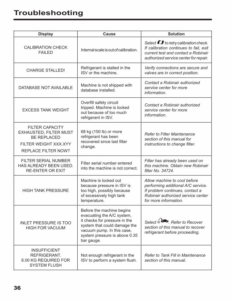
CALIBRATION CHECK FAILED Internal scale is out of calibration.
Select to retry calibration check. If calibration continues to fail, exit current test and contact a Robinair authorized service center for repair.
CHARGE STALLED! Refrigerant is stalled in the ISV or the machine.
Verify connections are secure and valves are in correct position.
DATABASE NOT AVAILABLE Machine is not shipped with database installed.
Contact a Robinair authorized service center for more information.
EXCESS TANK WEIGHT
Overfill safety circuit tripped. Machine is locked out because of too much refrigerant in ISV.
Contact a Robinair authorized service center for more information.
FILTER CAPACITY EXHAUSTED, FILTER MUST
BE REPLACEDFILTER WEIGHT XXX.XYYREPLACE FILTER NOW?
68 kg (150 lb) or more refrigerant has been recovered since last filter change.
Refer to Filter Maintenance section of this manual for instructions to change filter.
FILTER SERIAL NUMBER HAS ALREADY BEEN USED.
RE-ENTER OR EXIT
Filter serial number entered into the machine is not correct.
Filter has already been used on this machine. Obtain new Robinair filter No. 34724.
HIGH TANK PRESSURE
Machine is locked out because pressure in ISV is too high, possibly because of excessively high tank temperature.
Allow machine to cool before performing additional A/C service. If problem continues, contact a Robinair authorized service center for more information.
INLET PRESSURE IS TOO HIGH FOR VACUUM
Before the machine begins evacuating the A/C system, it checks for pressure in the system that could damage the vacuum pump. In this case, system pressure is above 0.35 bar gauge.
Select . Refer to Recover section of this manual to recover refrigerant before proceeding.
INSUFFICIENT REFRIGERANT.
6.00 KG REQUIRED FOR SYSTEM FLUSH
Not enough refrigerant in the ISV to perform a system flush.
Refer to Tank Fill in Maintenance section of this manual.
37
Troubleshooting
Display Cause Solution
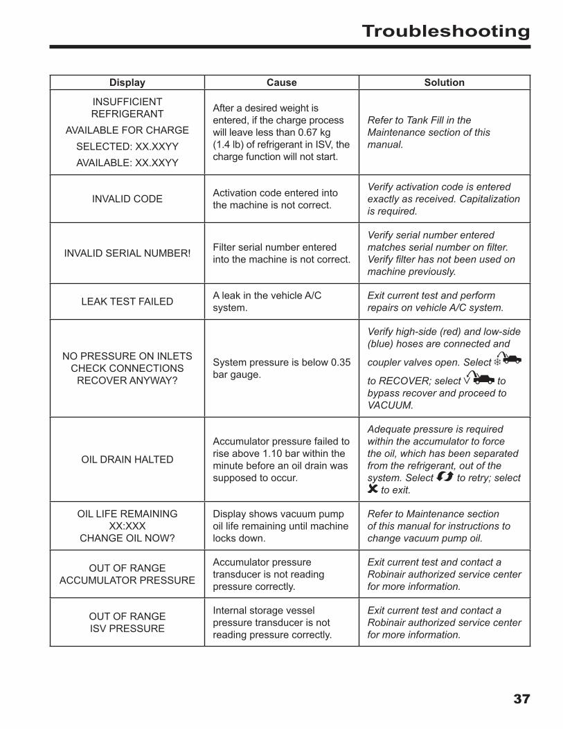
INSUFFICIENT REFRIGERANT
AVAILABLE FOR CHARGESELECTED: XX.XXYYAVAILABLE: XX.XXYY
After a desired weight is entered, if the charge process will leave less than 0.67 kg (1.4 lb) of refrigerant in ISV, the charge function will not start.
Refer to Tank Fill in the Maintenance section of this manual.
INVALID CODE Activation code entered into the machine is not correct.
Verify activation code is entered exactly as received. Capitalization is required.
INVALID SERIAL NUMBER! Filter serial number entered into the machine is not correct.
Verify serial number entered matches serial number on filter. Verify filter has not been used on machine previously.
LEAK TEST FAILED A leak in the vehicle A/C system.
Exit current test and perform repairs on vehicle A/C system.
NO PRESSURE ON INLETS CHECK CONNECTIONS
RECOVER ANYWAY?
System pressure is below 0.35 bar gauge.
Verify high-side (red) and low-side (blue) hoses are connected and
coupler valves open. Select
to RECOVER; select to bypass recover and proceed to VACUUM.
OIL DRAIN HALTED
Accumulator pressure failed to rise above 1.10 bar within the minute before an oil drain was supposed to occur.
Adequate pressure is required within the accumulator to force the oil, which has been separated from the refrigerant, out of the system. Select to retry; select
to exit.
OIL LIFE REMAINING XX:XXX
CHANGE OIL NOW?
Display shows vacuum pump oil life remaining until machine locks down.
Refer to Maintenance section of this manual for instructions to change vacuum pump oil.
OUT OF RANGE ACCUMULATOR PRESSURE
Accumulator pressure transducer is not reading pressure correctly.
Exit current test and contact a Robinair authorized service center for more information.
OUT OF RANGE ISV PRESSURE
Internal storage vessel pressure transducer is not reading pressure correctly.
Exit current test and contact a Robinair authorized service center for more information.
38
Troubleshooting
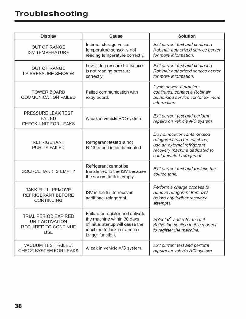
Display Cause Solution
OUT OF RANGE ISV TEMPERATURE
Internal storage vessel temperature sensor is not reading temperature correctly.
Exit current test and contact a Robinair authorized service center for more information.
OUT OF RANGE LS PRESSURE SENSOR
Low-side pressure transducer is not reading pressure correctly.
Exit current test and contact a Robinair authorized service center for more information.
POWER BOARD COMMUNICATION FAILED
Failed communication with relay board.
Cycle power. If problem continues, contact a Robinair authorized service center for more information.
PRESSURE LEAK TEST FAILED
CHECK UNIT FOR LEAKSA leak in vehicle A/C system. Exit current test and perform
repairs on vehicle A/C system.
REFRIGERANT PURITY FAILED
Refrigerant tested is not R-134a or it is contaminated.
Do not recover contaminated refrigerant into the machine; use an external refrigerant recovery machine dedicated to contaminated refrigerant.
SOURCE TANK IS EMPTYRefrigerant cannot be transferred to the ISV because the source tank is empty.
Exit current test and replace the source tank.
TANK FULL. REMOVE REFRIGERANT BEFORE
CONTINUING
ISV is too full to recover additional refrigerant.
Perform a charge process to remove refrigerant from ISV before any further recovery attempts.
TRIAL PERIOD EXPIRED UNIT ACTIVATION
REQUIRED TO CONTINUE USE
Failure to register and activate the machine within 30 days of initial startup will cause the machine to lock out and no longer function.
Select and refer to Unit Activation section in this manual to register the machine.
VACUUM TEST FAILED. CHECK SYSTEM FOR LEAKS A leak in vehicle A/C system. Exit current test and perform
repairs on vehicle A/C system.
39
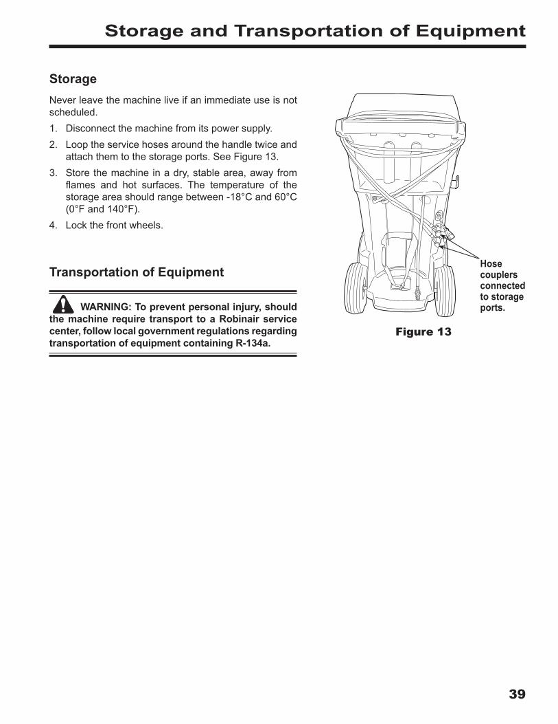
StorageNever leave the machine live if an immediate use is not scheduled.1. Disconnect the machine from its power supply.2. Loop the service hoses around the handle twice and
attach them to the storage ports. See Figure 13.3. Store the machine in a dry, stable area, away from
flames and hot surfaces. The temperature of thestorage area should range between -18°C and 60°C(0°F and 140°F).
4. Lock the front wheels.
Transportation of Equipment
WARNING: To prevent personal injury, should the machine require transport to a Robinair service center, follow local government regulations regarding transportation of equipment containing R-134a .
Storage and Transportation of Equipment
Figure 13
Hose couplers connected to storage ports .

40
Disposal of Equipment
At the end of its useful life, dispose of the R-134a machine according to current government regulations.• Public administration and producers of electrical / electronic equipment (EEE) are involved
in facilitating the processes of the re-use and recovery of waste electrical / electronicequipment through the organization of collection activities and the use of appropriateplanning arrangements.
• Do not dispose of this equipment as miscellaneous solid municipal waste. Arrange to haveit collected separately. Unauthorized disposal of waste electrical / electronic equipment ispunishable by law with appropriate penalties.
• The reuse and correct recycling of electrical / electronic equipment (EEE) is required forthe protection of the environment and the well-being of humans.
Disposal of Recycled MaterialsIt is the responsibility of the user to determine if a material is a hazardous waste at the time of disposal. The user must ensure compliance with all applicable laws and regulations.1. Deliver the refrigerant recovered from A/C systems to gas suppliers for recycling or disposal.2. Deliver the lubricants extracted from A/C systems to used oil collection centers.3. Review the laws in your jurisdiction to determine correct disposal procedures for pump oil.
Disposal of the Machine1. Detach and vent the gas from the machine circuit. Completely discharge the refrigerant tank in compliance
with current government regulations.2. Deliver the machine to an appropriate disposal center.
Disposal of BatteriesAt the end of their useful life, dispose of batteries according to current government regulations. Batteries must be recycled or disposed of correctly. Do not throw away batteries as part of normal refuse disposal.
WARNING: To prevent personal injury, do not throw batteries into open flame.