Embed Size (px)
Citation preview

1REV 6 - 0803111555 No.L-A2-21508
Models
C.S.A. CERTIFIED GLOWING EMBERS GAS FIREPLACE
LOG SET
Owner’s Manual
ROBERT H. PETERSON CO.
®
ROBERT H. PETERSON CO. • 14724 East Proctor Avenue • City of Industry, CA 91746
G46 BURNER SERIES
Do not store or use gasoline or other fl ammable vapors and liquids in the vicinity of this or any other appliance.WHAT TO DO IF YOU SMELL GAS:• Open a window.• Do not try to light any appliance.• Do not touch any electrical switch; do
not use any phone in the building.• Immediately call the gas supplier from
a neighbor’s phone and follow the gas supplier’s instructions.
• If you cannot reach the gas supplier, call the fi re department.
WARNING If the information in this manual is not followed exactly, a fi re or explosion may result, causing property damage, personal injury, or loss of life.
Installation and service must be performed by an NFI Certifi ed or other qualifi ed professional installer, service agency, or the gas supplier.
Important: Read these instructions carefully before starting installation of the log set.
The Peterson Real-Fyre® gas log set is to be installed only in a solid-fuel-burning fi replace with a working fl ue constructed of noncombustible material. Solid fuels shall not be burned in a fi replace where this gas log set is installed. The installation, including provisions for combustion, ventilation air, and required minimum permanent vent opening, must conform with the National Fuel Gas Code (ANSI Z223.1/NFPA 54) and applicable local building codes. In Canada, the installation must conform with the Natural Gas and Propane Storage and Handling Installation Code (CSA-B-149.1). A damper stop clamp is included to maintain the minimum permanent vent opening and to prevent full closure of the damper blade. The chimney damper must be fi xed fully opened when burning this log set. This log set is designed to burn with yellow fl ames; thus, adequate ventilation is absolutely necessary.
INSTALLER & CONSUMERThese instructions MUST be retainedwith this appliance.
Important: To comply with certifi cation, listings, and building code acceptances, and for safe operation and proper performance of this log set, use ONLY Peterson Real-Fyre® parts and accessories. Use of other controls, parts, or accessories that are not approved for use with Real-Fyre® gas log sets is prohibited and will void all warranties, certifi cations, listings, and building code approvals, and may cause property damage, personal injury, or loss of life.
G46-18/20-01(P)G46-18/20-11(M)(P)G46-18/20-15(M)(P)G46-18/20-17(M)(P)
G46-18/20(P)
G46-24-01(P)G46-24-11(M)(P)G46-24-15(M)(P)G46-24-17(M)(P)
G46-24(P)
G46-30-01(P)G46-30-11(M)(P)G46-30-15(M)(P)G46-30-17(M)(P)
G46-30(P)

2REV 6 - 0803111555 No.L-A2-21508
Le Real-Fyre® ensemble de notation de gaz de Peterson doit être installé seulement dans une cheminée brûlante de plein-carburant avec une conduite de cheminée fonctionnante construite avec du matériel non-combustible. Des combustibles solides ne seront pas brûlés dans une cheminée où cet ensemble de notation de gaz est installé. L’installation, y compris des dispositions pour la combustion, air de ventilation et ouverture permanente minimum exigée de passage, doit se conformer au code national de gaz de carburant (norme ANSI Z223.1/NFPA 54) et aux codes de bâtiment locaux applicables. Au Canada, l’installation doit se conformer au stockage de gaz naturel et de propane et à manipuler le code d’installation (CSA-B-149.1). Une bride plus humide d’arrêt est incluse pour maintenir l’ouverture permanente minimum de passage et pour empêcher la pleine fermeture de la lame plus humide. L’amortisseur de cheminée devrait être entièrement ouvert en brûlant l’ensemble de notation. L’ensemble de notation est conçu pour brûler avec les fl ammes jaunes; ainsi à ventilation proportionnée est absolument nécessaire.
Important: Lisez des directives de l'installation avec soin avant de commencer installation d'ensemble de la grosse buche.
AVERTISSEMENT: Si les informations dans ce manuel ne sont pas suivies exactement, un feu ou explosion peut résulter cause propriété endommage, blessure personnelle ou perte de vie.
Ne mettez pas en réserve ou utilisez de l'essence ou autre vapeurs infl ammables et liquides dans le voisinage de celui-ci ou tout autre appareil.CE QUI Faire Si VOUS avez SENTI le GAZ
• Ouvrez une fenêtre.• N'essaie pas d'allumer de l'appareil.• Ne touche pas de changement électrique; ne
utilisez pas du téléphone dans votre bâtiment.• Appelle Immédiatement votre fournisseur du gaz
du téléphone d'un voisin et suit les directives des fournisseur du gaz.
• Si vous ne pouvez pas atteindre votre fournisseur du gaz, appelle le département du feu.
L’installation et service doivent être exécutés par un NFI Certifi ed ou autre installateur qualifi é professionnel, agence du service ou le fournisseur du gaz.
INSTALLATEUR & CONSOMMATEURCes directives doivent être retenues avec
cet appareil.
MANUELMANUELOWNERSOWNERS
G46 BRÛLEUR SÉRIE
C.S.A. ENSEMBLE DE LA GROSSE BÛCHE
DE LA CHEMINÉE DU GAZ DES
CENDRES ARDENTES ENTHOUSIASTE
CERTIFIÉ
Models
ROBERT H. PETERSON CO.
®
Important: Pour se conformer à la certifi cation, les listes et les acceptations de code de bâtiment, et pour l’exploitation sûre et l’exécution appropriée de cet ensemble de notation, utilisent SEULEMENT de Real-Fyre® pièces et accessoires de Peterson. L’utilisation d’autres commandes, pièces, ou accessoires qui ne sont pas approuvés pour l’usage avec de Real-Fyre® ensembles de notation de gaz est interdite et videra toutes les garanties, certifi cations, listes, et approbations de code de bâtiment, et peut causer des dégats matériels, des blessures, ou la perte de la vie.
G46-18/20-01(P)G46-18/20-11(M)(P)G46-18/20-15(M)(P)G46-18/20-17(M)(P)
G46-18/20(P)
G46-24-01(P)G46-24-11(M)(P)G46-24-15(M)(P)G46-24-17(M)(P)
G46-24(P)
G46-30-01(P)G46-30-11(M)(P)G46-30-15(M)(P)G46-30-17(M)(P)
G46-30(P)
3REV 6 - 0803111555 No.L-A2-21508
TABLE OF CONTENTSPARTS LIST (REMOTE UNITS) 4PARTS LIST (MANUAL UNIT) 5SAFETY CONTROL SYSTEM FOR G46 MANUAL 6SAFETY CONTROL SYSTEM FOR G46-11(M)(P) 6SAFETY CONTROL SYSTEM FOR G46-01(P) 7SAFETY CONTROL SYSTEM FOR G46-15(M)(P) 7SAFETY CONTROL SYSTEM FOR G46-17(M)(P) 8PRE-INSTALLATION AND FIREPLACE PREPARATION SAFETY 9IMPORTANT INFORMATION 11DAMPER STOP CLAMP INSTRUCTIONS 12INSTALLING THE GAS LOG SET 12
DAMPER CLAMP INSTRUCTIONS 12CONNECTING THE IGNITION PACK TO THE G46-01(P) VALVE 14INSTALLING OR REPLACING BATTERIES FOR IGNITION MODULE PACK 14SECURING THE BURNER 15GRANULE PLACEMENT 15EMBER PLACEMENT 15GRATE PLACEMENT 15
WOODLAND OAK LOG PLACEMENT 16EMBER BED SETUP 18WESTERN CAMPFYRETM LOG PLACEMENT 19LIGHTING INSTRUCTIONS - MANUAL PILOT AND SERIES 17 VALVE 21LIGHTING INSTRUCTIONS - SERIES 11 VALVE 23LIGHTING INSTRUCTIONS - 01 VALVE 25LIGHTING INSTRUCTIONS - SERIES 15 VALVE 27PILOT BURNER ADJUSTMENT (G46 MANUAL) 28PILOT BURNER ADJUSTMENT (G46-11) 28PILOT BURNER ADJUSTMENT (G46-17) 28FLAME PATTERN ADJUSTMENT (ALL MODELS) 29AVAILABLE ACCESSORIES FOR THE GAS BURNER SYSTEM 30WARRANTY 32
This appliance may be installed in an aftermarket, permanently located, manufactured (mobile) home, where not prohibited by local codes.
Installation of appliances designed for manufactured homes or mobile homes must conform with Manufactured Home Construction and Safety Standard, Title 24 CFR, Part 3280 in the U.S. and CAN/CSA Z240 MH in Canada or by ANSI/NCSBCS A225.1/NFPA 501A, Manufactured Home Installations Standard when such standard is not applicable.

4REV 6 - 0803111555 No.L-A2-21508
PARTS LIST (REMOTE UNITS)Log styles, sizes, and parts will vary depending upon the G46 Series model ordered. When ordering replacement parts, be sure to indicate your log set model.
Note: Only the logs for the WO-24 Woodland Oak 24" set are illustrated and listed below.
16
15
2
15
6
3
4
7
14
13Note: Photos not to scale.
Actual parts may differ.
8
G46-15 burner(top view)
G46-01 electronic burner(top view)
G46-11 burner(top view)
Item no.
Description
1. 20" rear log2. 24" front log3. 15" top left log4. 15" top right log5. 9" top left log6. 8" top log7. Grate8. Log locators with screws (2)9. Burner pan assembly
10. G46 safety control system (see p. 6-8)11. Piezo ignitor assembly (series 11 & 17 valve)12. Pilot assembly (natural)or Pilot assembly (propane)13. Sand granules (natural gas)or Vermiculite granules (propane gas)14. Glowing embers15. Damper clamp16. Connector kit17. Ember bed (supplied with charred log sets)
17
10
12911
Order parts through your local Real-Fyre®
dealer.
G46-17 burner(top view)

5REV 6 - 0803111555 No.L-A2-21508
PARTS LIST (MANUAL UNIT)
16
15
2
15
6
3
4
7
1413
Note: Photos not to scale.
Actual parts may differ.
12
9
11
G46 burner with manual control (top view)
8
Item no.
Description
1. 20" rear log2. 24" front log3. 15" top left log4. 15" top right log5. 9" top left log6. 8" top log7. Grate8. Log locators with screws (2)9. Burner pan assembly
10. G46 safety control system (see p. 6)11. Piezo ignitor assembly12. Pilot assembly (natural)or Pilot assembly (propane)13. Sand granules (natural gas)or Vermiculite granules (propane gas)14. Glowing embers15. Damper clamp16. Connector kit17. Ember bed (supplied with charred log sets)
17
Log styles, sizes, and parts will vary depending upon the G46 Series model ordered. When ordering replacement parts, be sure to indicate your log set model.
Note: Only the logs for the WO-24 Woodland Oak 24" set are illustrated and listed below.
Order parts through your local Real-Fyre® dealer.
10
6REV 6 - 0803111555 No.L-A2-21508
SAFETY CONTROL SYSTEM FOR G46 MANUAL
SAFETY CONTROL SYSTEM FOR G46-11(M)(P)
G46 burner showing valve layout under heat shield
22
24
18
20
19
21
Pilot assembly(rear view)
Location of orifi ce
Pilot assembly
Ceramic electrode
DO NOT REMOVE HEAT SHIELD
G46 burner showing valve layout under heat shield (rear view)
DO NOT REMOVE HEAT SHIELD
Item no.
Description
18. Safety control valve assembly (regulated)19. Pilot assembly20. Handle assembly21. Adapter elbow
Item no.
Description
22. Safety control valve23. Pilot assembly24. Brass elbow 1/2" fl are x 3/8" MIP
23
Regulator

7REV 6 - 0803111555 No.L-A2-21508
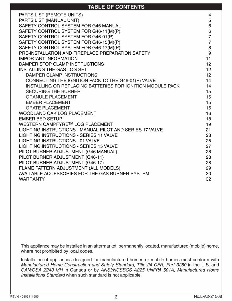
SAFETY CONTROL SYSTEM FOR G46-01(P)
SAFETY CONTROL SYSTEM FOR G46-15(M)(P)
Flame height control knob
VR-1A remote with receiver, heat shield, batteries, & wiring (if equipped)
ON/OFF IGN/PILOT knob
Connection terminals for VR-1A wiring to receiver
26
25
27
28
Without heat shield
G46 burner showing remote-control valve layout under heat shield
DO NOT REMOVE HEAT SHIELD
G46 burner showing 15 valve layout under heat shield
DO NOT REMOVE HEAT SHIELD
Item no.
Description
25. Safety control valve26. Pilot assembly
Item no.
Description
27. Safety control valve28. Pilot assembly29. VR-1A Remote kit
29

8REV 6 - 0803111555 No.L-A2-21508
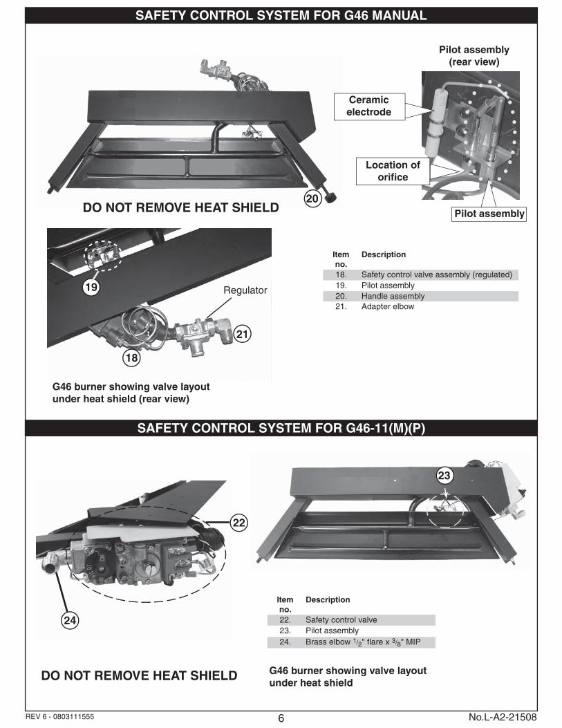
SAFETY CONTROL SYSTEM FOR G46-17(M)(P)G46 burner showing 17 valve layout under heat shield
DO NOT REMOVE HEAT SHIELD
Item no.
Description
30. Safety control valve31. Pilot assembly32. VR-1A Remote kit
30
Pilot assembly(rear view)
Optional manual system or upgrade to VR-2 remote system.
VR-1A remote with receiver, heat shield, batteries, & wiring (if equipped)
31
32
To remote receiver
To remote receiver
Regulator
Input from gas supply
Pilot gas line
Thermocouple line
Thermocouple
Electrode

9
PRE-INSTALLATION AND FIREPLACE PREPARATION SAFETY
A. This appliance is designed as an attended appliance. Adults must be present when this gas appliance is operating. Do not leave this unit burning when unattended or while anyone is sleeping.
B. This appliance is only for use with the type of gas indicated on the rating plate. This appliance is NOT FIELD CONVERTIBLE for use with other gasses.
C. BE CAREFUL: If not installed, serviced, and used correctly per these instructions, this product can cause serious personal injury, property damage, or loss of life.
PRE-INSTALLATION AND FIREPLACE PREPARATION SAFETY GUIDELINES
D. WARNING: Before installing in a solid-fuel-burning fi replace, the chimney fl ue, damper, and fi rebox must be thoroughly CLEANED of soot, creosote, ashes, and loose paint, and must be inspected by a qualifi ed chimney cleaner. Some older fi replaces may need repair prior to installing this appliance.
E. CHECK GAS TYPE (natural or propane): The gas supply must be the same as stated on your burner system rating plate. If gas supply is different, DO NOT INSTALL. Contact your dealer for immediate assistance.
F. Any outside air ducts and/or ash dumps located on the fl oor or walls of the fi replace must be permanently sealed shut before the installation. Use a heat-resistant sealant. Do not seal the chimney fl ue damper.
G. INSUFFICIENT GAS PRESSURE WILL KEEP THE PILOT FROM OPERATING PROPERLY. DO NOT USE IF GAS PRESSURE IS LOWER THAN THE MINIMUM REQUIREMENT.
H. The minimum inlet gas-supply pressure for purposes of input adjustment is 5" water column (w.c.) on natural gas and 11" w.c. on propane gas. Insuffi cient gas pressure will affect proper operation of the pilot. Do not install this gas appliance if minimum pressure is not available. The maximum inlet gas-supply pressure is 10.5" w.c. on natural gas and 13" w.c. on propane gas. The propane source must be regulated. (Do not connect this appliance directly to an unregulated propane gas tank - this can cause an explosion.)
I. The gas piping system must be sized to provide minimum inlet pressure at the maximum fl ow rate (BTU/hr). Undue pressure loss will occur if the pipe is too small, or the run is too long.
J. Input ratings shown in BTU per hour are for elevations up to 2,000 ft. For elevations above 2,000 ft., refer to the National Fuel Gas Code or contact the Robert H. Peterson Company before installing this product.
K. This gas appliance and its main gas valve must be disconnected from the gas-supply piping system during any pressure testing of that system at test pressures in excess of 1/2 psig.
L. This gas appliance must be isolated from the gas-supply piping system by closing the equipment shutoff valve connected to the gas-supply line during any pressure testing of the gas-supply piping system at test pressures equal to or less than 1/2 psig.
M. Do not use this appliance if any part has been underwater. Immediately call a qualifi ed service technician to inspect the appliance and to replace any part of the control system and any gas control that has been underwater.
CAUTION: Installation and repair must be done by an NFI Certifi ed or other qualifi ed professional installer.
Installer: Carefully read these instructions before installing this gas burner system. Be sure you understand all safety precautions and warnings contained in this manual.
10
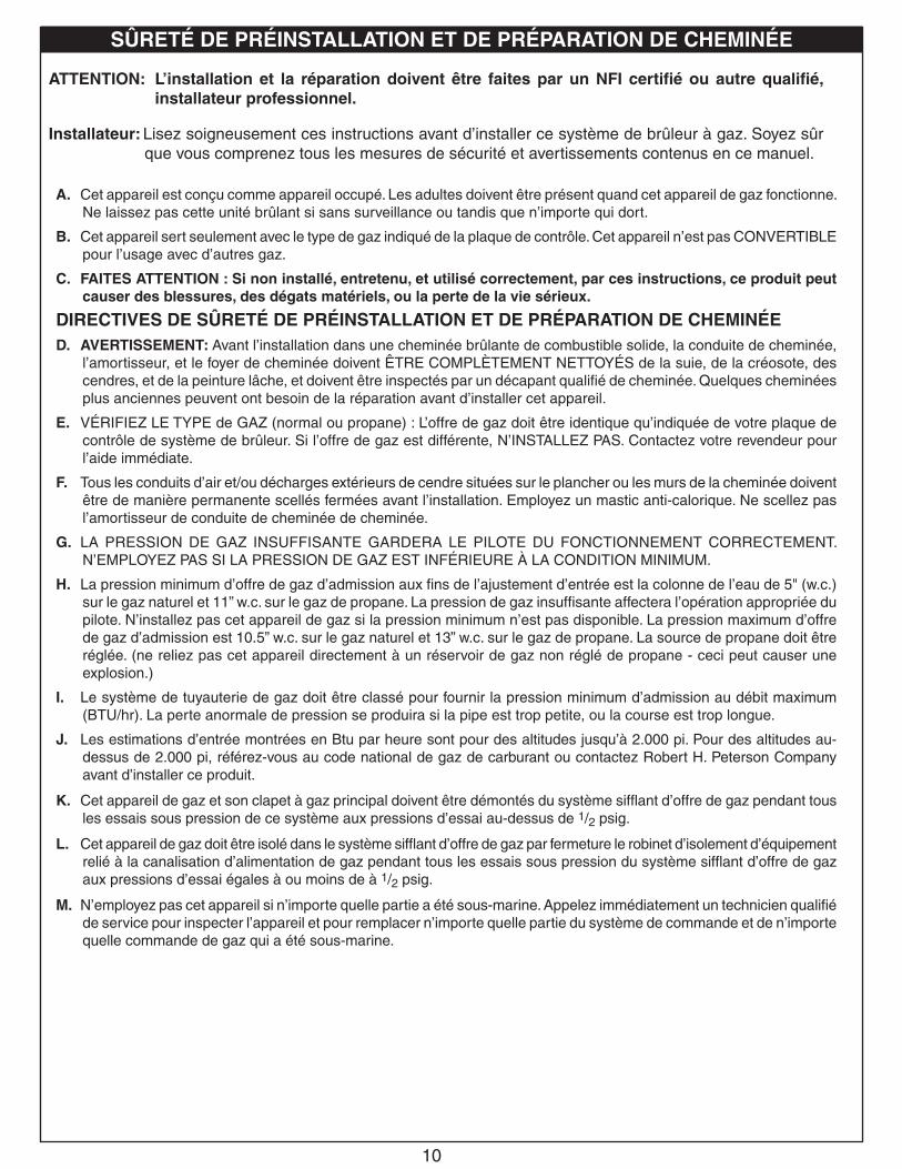
SÛRETÉ DE PRÉINSTALLATION ET DE PRÉPARATION DE CHEMINÉE
A. Cet appareil est conçu comme appareil occupé. Les adultes doivent être présent quand cet appareil de gaz fonctionne. Ne laissez pas cette unité brûlant si sans surveillance ou tandis que n’importe qui dort.
B. Cet appareil sert seulement avec le type de gaz indiqué de la plaque de contrôle. Cet appareil n’est pas CONVERTIBLE pour l’usage avec d’autres gaz.
C. FAITES ATTENTION : Si non installé, entretenu, et utilisé correctement, par ces instructions, ce produit peut causer des blessures, des dégats matériels, ou la perte de la vie sérieux.
DIRECTIVES DE SÛRETÉ DE PRÉINSTALLATION ET DE PRÉPARATION DE CHEMINÉED. AVERTISSEMENT: Avant l’installation dans une cheminée brûlante de combustible solide, la conduite de cheminée,
l’amortisseur, et le foyer de cheminée doivent ÊTRE COMPLÈTEMENT NETTOYÉS de la suie, de la créosote, des cendres, et de la peinture lâche, et doivent être inspectés par un décapant qualifi é de cheminée. Quelques cheminées plus anciennes peuvent ont besoin de la réparation avant d’installer cet appareil.
E. VÉRIFIEZ LE TYPE de GAZ (normal ou propane) : L’offre de gaz doit être identique qu’indiquée de votre plaque de contrôle de système de brûleur. Si l’offre de gaz est différente, N’INSTALLEZ PAS. Contactez votre revendeur pour l’aide immédiate.
F. Tous les conduits d’air et/ou décharges extérieurs de cendre situées sur le plancher ou les murs de la cheminée doivent être de manière permanente scellés fermées avant l’installation. Employez un mastic anti-calorique. Ne scellez pas l’amortisseur de conduite de cheminée de cheminée.
G. LA PRESSION DE GAZ INSUFFISANTE GARDERA LE PILOTE DU FONCTIONNEMENT CORRECTEMENT. N’EMPLOYEZ PAS SI LA PRESSION DE GAZ EST INFÉRIEURE À LA CONDITION MINIMUM.
H. La pression minimum d’offre de gaz d’admission aux fi ns de l’ajustement d’entrée est la colonne de l’eau de 5" (w.c.) sur le gaz naturel et 11” w.c. sur le gaz de propane. La pression de gaz insuffi sante affectera l’opération appropriée du pilote. N’installez pas cet appareil de gaz si la pression minimum n’est pas disponible. La pression maximum d’offre de gaz d’admission est 10.5” w.c. sur le gaz naturel et 13” w.c. sur le gaz de propane. La source de propane doit être réglée. (ne reliez pas cet appareil directement à un réservoir de gaz non réglé de propane - ceci peut causer une explosion.)
I. Le système de tuyauterie de gaz doit être classé pour fournir la pression minimum d’admission au débit maximum (BTU/hr). La perte anormale de pression se produira si la pipe est trop petite, ou la course est trop longue.
J. Les estimations d’entrée montrées en Btu par heure sont pour des altitudes jusqu’à 2.000 pi. Pour des altitudes au-dessus de 2.000 pi, référez-vous au code national de gaz de carburant ou contactez Robert H. Peterson Company avant d’installer ce produit.
K. Cet appareil de gaz et son clapet à gaz principal doivent être démontés du système siffl ant d’offre de gaz pendant tous les essais sous pression de ce système aux pressions d’essai au-dessus de 1/2 psig.
L. Cet appareil de gaz doit être isolé dans le système siffl ant d’offre de gaz par fermeture le robinet d’isolement d’équipement relié à la canalisation d’alimentation de gaz pendant tous les essais sous pression du système siffl ant d’offre de gaz aux pressions d’essai égales à ou moins de à 1/2 psig.
M. N’employez pas cet appareil si n’importe quelle partie a été sous-marine. Appelez immédiatement un technicien qualifi é de service pour inspecter l’appareil et pour remplacer n’importe quelle partie du système de commande et de n’importe quelle commande de gaz qui a été sous-marine.
ATTENTION: L’installation et la réparation doivent être faites par un NFI certifi é ou autre qualifi é, installateur professionnel.
Installateur: Lisez soigneusement ces instructions avant d’installer ce système de brûleur à gaz. Soyez sûr que vous comprenez tous les mesures de sécurité et avertissements contenus en ce manuel.

11
IMPORTANT INFORMATIONDo not use this log set if any part has been underwater. Immediately call a qualified professional service technician to inspect the appliance and to replace any part of the control system and any gas control that has been underwater.
The appliance and its individual shutoff valve must be disconnected from the gas-supply piping system when testing the system at test pressures in excess of ½ psig. This is accomplished by closing the gas-supply line valve.
Keep the area of the gas log set clear and free from combustible materials, gasoline, and other fl ammable vapors and liquids.
The minimum inlet gas-supply pressure for the purpose of input adjustment is 5" for natural gas and 11" for propane gas. The maximum inlet gas-supply pressure for this burner is 14" for natural and propane gas.
A fi replace screen must be in place when the log set is burning. Provisions for adequate combustion air must be maintained. Unless other provisions for combustion air are provided, the screen shall have an opening(s) for introduction of combustion air.Combustion air is adequate when all fl ames curl into the fi replace and away from the screen.
When glass fi replace doors are used, operate the gas log set with the doors open.
The minimum-size fi replace in which the log set is to be installed is listed in the technical data table below. The minimum chimney height from the hearth to the top of the chimney is 15'..
THIS GAS LOG SET CONFORMS TO THEANSI Z21.60b -2004 STANDARD.
Note: A damper stop clamp is provided as a means to prevent full closure of the damper blade. Fully open the damper when burning the log set (see the next page for details on the damper clamp).
The log set is designed to burn with yellow fl ames; adequate ventilation is absolutely necessary.
The chimney damper must be fi xed in a manner to maintain the permanent free opening at all times. To accomplish this, you may install a screw or bolt in the edge of the damper to prevent closing, drill holes in the damper, or remove the damper.
Important: To comply with certifi cation, listings, and building code acceptances, and for safe operation and proper performance of this log set, use ONLY Peterson Real-Fyre® parts and accessories. Use of other controls, parts, and accessories that are not designed for use with Real-Fyre® gas log sets is prohibited and will void all warranties, certifi cations, listings, and building code approvals, and may cause property damage, personal injury, or loss of life.
Log setsize
Minimum fi rebox dimensions BTU Rating
Front opening
Depth Height Natural Propane
18" 24" 15" 18" 40,000 40,000
20" 26" 15" 18" 40,000 40,000
24" 30" 15" 18" 55,000 55,000
30" 36" 15" 18" 65,000 65,000
Minimum permanent free opening area of chimney damper for venting
For factory-built fi replaceslog set sizes
For masonry-built fi replaceslog set sizes
Chimney height
18" 20" 24" 30" 18" 20" 24" 30"
15' 15 sq. in. 15 sq. in. 21 sq. in. 29 sq. in. 23 sq. in. 23 sq. in. 31 sq. in. 40 sq. in.
20' 14 sq. in. 14 sq. in. 18 sq. in. 24 sq. in. 21 sq. in. 21 sq. in. 28 sq. in. 36 sq. in.
30' 10 sq. in. 10 sq. in. 15 sq. in. 19 sq. in. 19 sq. in. 19 sq. in. 26 sq. in. 33 sq. in.

12
DAMPER CLAMP INSTRUCTIONS
The damper clamp with hex bolt (Fig. 12-1) is provided as a means to prevent full closure of the damper blade. The clamp is easily attached to most damper blades with pliers or a wrench, and must be permanently installed. The clamp is designed to prevent accidental closure of the damper when installed as illustrated (Fig. 12-2 & Fig. 12-3). Should the clamp not fi t or provide the permanent vent opening listed on the table found on the previous page, have a permanent stop installed, remove the damper blade, or have the damper cut to provide the minimum permanent opening required.
DAMPER STOP CLAMP INSTRUCTIONS
The Peterson Real-Fyre® gas log set must be installed by an NFI Certifi ed or other qualifi ed professional installer. Instructions must be followed carefully to ensure proper performance and an aesthetically pleasing product. Check to be sure the log set is designed and labeled for the type of gas (natural or propane gas) supplied to the fi replace. Never use a log set designed for natural gas with propane gas, or a log set designed for propane gas with natural gas. Real-Fyre® gas logs must be installed only in a wood-burning fi replace with the minimum venting requirements met (see the previous page). Fireplace fl oor must be level, clean, and smooth. Check PARTS LIST to be sure all parts are included. Gas-supply pipe inside diameter (I.D.) must be 1/2" or larger. 3/4" I.D. may be necessary if gas line is longer than 20'.
You should adjust and align the pilot prior to installing by using the fl ex connector kit (Item 16). Attach the connector kit to the gas supply and the burner outside the fi replace. This will allow you to move the burner at an angle in order to access the pilot adjustment screw on the valve (see the relevant PILOT BURNER ADJUSTMENT section).
WARNINGThis appliance is equipped for either natural or propane gas as indicated on the back cover. Field conversion is
not permitted.
INSTALLING THE GAS LOG SET
Damper clamp
Fig. 12-1
Set screw
Fig. 12-2 Fig. 12-3
Open Closed
Position of burner gas inlet valve on G46-11 model
Fig. 12-4 Large adapter
Gas supply
Elbow
Connector kit
Burner valve gas inlet

13
1. The burner gas inlet is located in front of the gas valve (Fig. 12-4). Use Tefl on tape or pipe compound on all pipe thread male connections, except where brass to brass.
FOR THE G46 AUTOMATIC MILLIVOLT VALVE Attach the connector kit 3/8" adapter to the brass elbow (Item 24) on the valve. The log set user should make themselves familiar with the valve control layout before installing the burner into the fi replace.
2. Next, clamp the log locators onto the outside grate fi ngers. The log locators will fi t on either side of the grate fi nger (see Fig. 13-1 & 13-2). Align the locator screw so that it projects down into the locator holes on the burner. Attach nuts to screws and fi nger-tighten only. Place the bottom log on the grate (see Fig. 13-3) and align the log against the locator. Fully tighten the screws and then remove the logs and grate until completing the gas connection and granule placement.
3. Position the burner in the center rear of the fi replace.
Connect the connector kit tubing (Item 16) to the gas supply. Be sure that the burner assembly and the valve remain in alignment. If the valve shifts position during installation, the burner assembly may not sit fl at in the fi replace, causing improper gas fl ow. It may also cause interference with the control knob operation.
• Make sure that the safety control system is in the OFF position.
• Turn on the gas to the fi replace and check for leaks at all connections by using a soapy water solution.
Never use an open fl ame to check for leaks. • Light the pilot (see the relevant LIGHTING
INSTRUCTIONS section) and check for proper adjustment. If the pilot needs to be adjusted, follow the relevant PILOT BURNER ADJUSTMENT section. Turn the pilot off.
• Position the grate on the burner (Fig. 13-3). Push the burner grate assembly as far as possible to the rear of the fi replace, then remove the grate.
Note: Refer to the PARTS LIST when following these instructions.
CAUTION: Turn off the gas to the fi replace before beginning this procedure.
Important: Log locators may be installed in either confi guration (A or B), depending on burner size. Adjust as necessary to ensure screws fi t in locator holes in burner. This secures the burner and grate from movement, and keeps the logs in place for optimum log set operation.
INSTALLING THE GAS LOG SET (Cont.)
Note: If the log set is a G46-01(P) model, continue following the instructions on p. 14. For all other models, proceed to p. 15.
Fig. 13-3
Log locator screw
Heat chamber
Burner
Grate
Log locators
Front bottom
log
Rear bottom
log
B
A
Note: Manual grate shown.
Fig. 13-1
Fig. 13-2
WARNINGFailure to position the parts in accordance with these diagrams or failure to use only parts specifi cally approved with this appliance may result in property damage or personal injury.

14
CONNECTING THE IGNITION PACK TO THE G46-01(P) VALVEThe G46-01-xx(P) valve comes complete with the wiring harness connected to the pine cone switch. You may wish to ensure it is correctly connected before fi nally connecting the three wires to the valve, as below.
PINE CONE PLACEMENT
The designer pine cone incorporating the control switch is aesthetically designed and is an integral part of the operation of the log set. The pine cone can be placed as close to the valve as you desire, but never closer than 4" from the fl ame.CAUTION: THE PINE CONE MAY
BE HOT DURING AND D I R E C T LY A F T E R OPERATION OF THE GAS LOG SET.
O(Drawings not to scale)
Wiring diagram for 01 remote switch
INSTALLING THE GAS LOG SET (Cont.)SPECIAL INSTRUCTIONS FOR G46-01-xx(P) MODELS
Installing pine cone with switch for 01M models
TO CHECK THE WIRING ASSEMBLY:
A. Check that the wiring harness is fi tted tightly into the connector on the green ignitor pack in the rear of the pine cone (Fig. 14-1).
B. Check that the female connectors on the two black wires from the pilot assembly (wires marked "I" and "S") are inserted fully into the male connectors on the ignitor pack (Fig. 14-2).
C. Check the connection of the red and black wires of the wire harness to the respective counterpart wires from the battery holder (red-red and black-black). The two brown wires should be connected to the switch.
Note: The two spare brown wires with coated male connectors are used to connect a remote system (if equipped).
D. Connect the wires to the valve in the following order (see Fig. 14-2):
Orange wire marked THTP - to THTP connector on valve Black wire marked TP - to TP connector on valveGreen wire marked TH - to TH connector on valveThe diagram below shows the wiring layout for the complete unit.
CHECK CONNECTIONS
“I” WIRE “S” WIRE
WIRE HARNESSCONNECT OR
IGNITOR PACK
AFig. 14-1
INSTALLING OR REPLACING BATTERIES FOR IGNITION MODULE PACK
Two 1.5-volt (D-cell) alkaline batteries are supplied with the log set. To install or replace batteries, remove the green ignition module pack, held in place with a Velcro strip, from the rear of the pine cone receiver (Fig. 14-3). Remove the battery holder and old batteries from the pine cone. Replace (or install) batteries into the battery holder, making sure they are installed according to the diagram in the battery holder. Replace the holder, pressing it fi rmly against the Velcro strip. Replace the ignition pack and press it fi rmly into place. The ignition system is now ready to operate.
Note: For the system to work properly, it is suggested that you replace the batteries annually with fresh batteries. Always replace all the batteries at the same time.
D
Fig. 14-2
Fig. 14-3
"S" wire
Velcro strips
Pine cone cover with switch
Battery holderwith batteries
Ignition module packSwitch
Pine cone2 wires to
switch(brown)
Ignitor pack
To battery holder (red)
Orange wire
marked THTP
Blackwire
markedTP
Green wire
marked THTP
To battery holder (black)
To pilot assembly probes Valve magnet
wire (black)(Do not remove)
G46electronic
valve
Orange (THTP)
I
SS
I
Green (TH)
Wire harness
Black (TP)
"I" wire
B
Check Connections
Wire harness connector
Ignitor pack
Fig. 14-4

15
SECURING THE BURNERThe gas log set has two securing holes at the front of the burner pan heat shield (see PARTS LIST and Fig. 15-1 for location). Mark the center point of each hole and drill a 3/16" pilot hole (one for each side) into the fi replace fl oor. Secure with 1/4" anchor bolts.
GRANULE PLACEMENTFill the burner pan completely with granules (Item 13). Slope the granules at the same angle as the burner pan. Do not allow granules to spill over the front lip, sides, or back of the burner. DO NOT PLACE GRANULES ON IGNITOR SHIELD OR KNOB SHIELD.
EMBER PLACEMENT
After breaking up any clumps, sprinkle embers (Item 14) lightly and evenly over the entire surface of the granules. You may sprinkle the embers (not the granules) over the knob and ignitor shields, making sure to keep the embers clear of the pilot assembly.
Embers around the pilot will block airfl ow, causing the pilot to overheat and shut down the system.
To check operation, light the pilot and burner (see the relevant LIGHTING INSTRUCTIONS section).
IMPORTANTFor all valves, the air MUST be purged from the gas line before the pilot will light and burn properly. The time needed to purge will depend on the length of the gas line to the unit and the amount of time since the unit or gas line was last used. It may take several minutes before all the air is purged and the pilot will light and burn properly. Follow the relevant LIGHTING INSTRUCTIONS in this manual.
INSTALLING THE GAS LOG SET (Cont.)
Fig. 15-124" unit shown
(11 valve)See parts list for grate differences
EmbersIgnitor shield
Log locator bolts
Pilot assembly
Burner securing
hole
GRATE PLACEMENT
Carefully center the grate (left to right) over the burner. The burner pipe should be behind (not directly under) the front bar of the grate. This will help prevent sooting. Next proceed to LOG PLACEMENT.
WARNINGFailure to position the parts in accordance with these diagrams or failure to use only parts specifi cally approved with this appliance may result in property damage or personal injury.
16
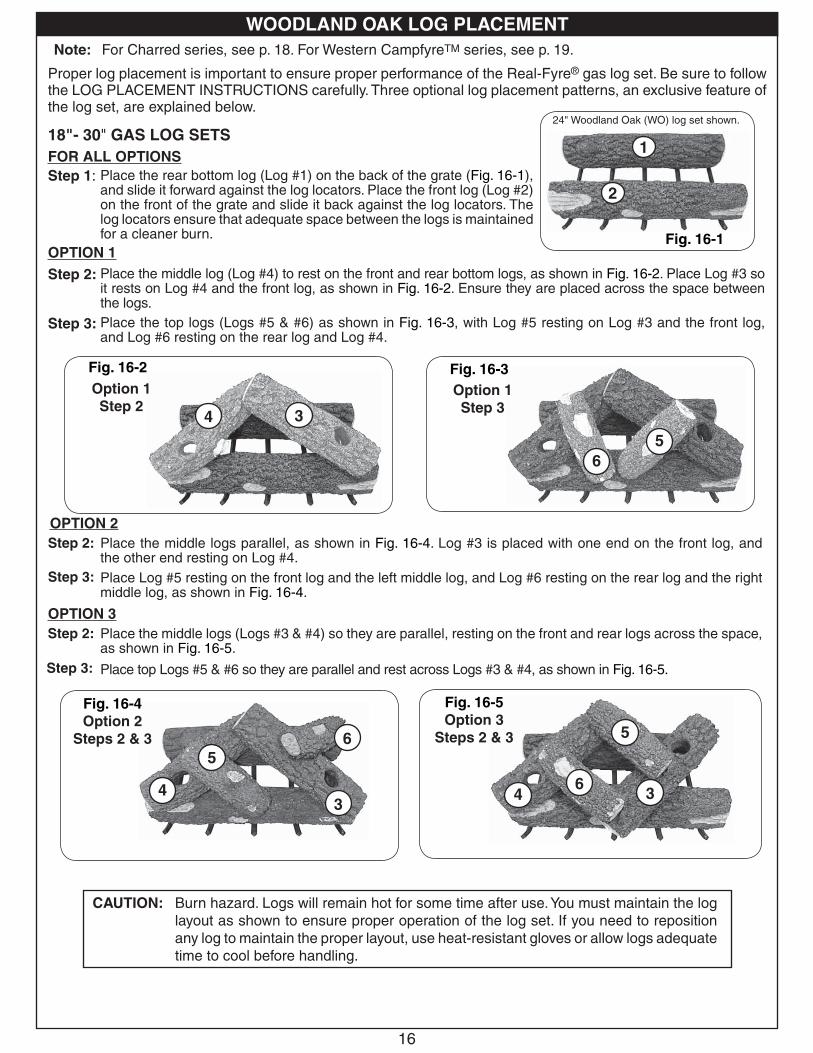
Note: For Charred series, see p. 18. For Western CampfyreTM series, see p. 19.
Proper log placement is important to ensure proper performance of the Real-Fyre® gas log set. Be sure to follow the LOG PLACEMENT INSTRUCTIONS carefully. Three optional log placement patterns, an exclusive feature of the log set, are explained below.
18"- 30" GAS LOG SETS FOR ALL OPTIONS
WOODLAND OAK LOG PLACEMENT
Fig. 16-4 Option 2
Steps 2 & 3
43
65
CAUTION: Burn hazard. Logs will remain hot for some time after use. You must maintain the log layout as shown to ensure proper operation of the log set. If you need to reposition any log to maintain the proper layout, use heat-resistant gloves or allow logs adequate time to cool before handling.
Fig. 16-5 Option 3
Steps 2 & 3
4
65
3
Option 1Step 2
Fig. 16-2
Option 1Step 3
Fig. 16-3
6
5
34
Fig. 16-1
2
1
24" Woodland Oak (WO) log set shown.
Step 1: Place the rear bottom log (Log #1) on the back of the grate (Fig. 16-1), and slide it forward against the log locators. Place the front log (Log #2) on the front of the grate and slide it back against the log locators. The log locators ensure that adequate space between the logs is maintained for a cleaner burn.
OPTION 1Step 2: Place the middle log (Log #4) to rest on the front and rear bottom logs, as shown in Fig. 16-2. Place Log #3 so
it rests on Log #4 and the front log, as shown in Fig. 16-2. Ensure they are placed across the space between the logs. Place the top logs (Logs #5 & #6) as shown in Fig. 16-3, with Log #5 resting on Log #3 and the front log, and Log #6 resting on the rear log and Log #4.
Step 3:
OPTION 2Step 2: Place the middle logs parallel, as shown in Fig. 16-4. Log #3 is placed with one end on the front log, and
the other end resting on Log #4.Step 3: Place Log #5 resting on the front log and the left middle log, and Log #6 resting on the rear log and the right
middle log, as shown in Fig. 16-4.
OPTION 3Place the middle logs (Logs #3 & #4) so they are parallel, resting on the front and rear logs across the space, as shown in Fig. 16-5.
Step 2:
Step 3: Place top Logs #5 & #6 so they are parallel and rest across Logs #3 & #4, as shown in Fig. 16-5.

17
WOODLAND OAK LOG PLACEMENT (Cont.)
The illustrations below (Fig. 17-2 through 17-4 and Fig. 17-5 through 17-7 for Split Oak) show the three basic log placement patterns available for G46 Real-Fyre® C.S.A. Certifi ed gas log sets. The mirror image of each of the illustrations is also approved. These log placement patterns are the acceptable patterns for all other sets.
OPTIONAL BONUS LOG PLACEMENT
The optional bonus log (included with Golden Oak Designer Plus and Split Oak Designer Plus log sets) should be placed directly above the front or rear bottom logs (Logs #1 & #2), so it does not extend into the space between the front and rear logs, as shown in Fig. 17-1.
Fig. 17-7
Fig. 17-6
Log #7
Fig. 17-1
Fig. 17-2
Fig. 17-4
Fig. 17-3
Fig. 17-5
OPTIONAL LOG PLACEMENT PATTERNS SUMMARY

18
If you have purchased this style of log set, follow the instructions below.Note: The logs for the CHD Charred Oak Set are illustrated.
Log styles and sizes will vary depending upon the Charred Series log set ordered.Note: INSTRUCTIONS ON THE EMBER BED MAY NOT BE APPLICABLE.
The ember bed (see Fig. 18-1), supplied with the charred log set, fi ts onto the back of the burner pan. Place it centrally on the back so the outer front tabs hang over the pan (see Fig. 18-2). Set it so it is over the pilot assembly, but high enough that it does not interfere with the operation of the pilot (see Fig. 18-1). Cover the surface of the ember bed with the glowing embers, supplied with the Charred series log set, making sure to keep the Glowing Embers clear of the pilot assembly. For best glowing performance, they should be applied evenly and pulled slightly apart so the fi bers are somewhat loose. (It is not necessary to pile the entire bag of the glowing embers.) Center fl ame must be clearly visible, or excessive sooting could occur.
Fig. 18-3 Fig. 18-4 Fig. 18-5 Fig. 18-6
Fig. 18-1 Fig. 18-2
EMBER BED SETUP
Step 1. Place the long bottom rear log (Log #1) on the back of the grate with the fl at, hollow side facing the rear of the fi replace. Push the log up against the log locators.
Step 2. Place the two sections of the front log (Logs #2L & #2R) on the front of the grate and up against the log locators. The charred sections should be facing each other, approximately 1" apart at the top.
Step 3. Place the two top, knot-hole logs (Logs #3 & #4) so that one end rests on each front log section and the other end rests on the rear log, as shown in Fig. 18-4. The charred sections should be over the opening between the front and rear logs.
Step 4. Place the top logs (Logs #5 & #6) as shown in Fig. 18-5, with Log #5 resting on the left-hand knot-hole log (Log #3) and the left front log (Log #2L), and Log #6 resting across both knot-hole logs to the rear.
Step 5. Place the additional top log (Log #7) so it rests on the right-hand knot-hole log (Log #4) and on the right front bottom log section (Log #2R), as shown in Fig. 18-6.
CHARRED OAK SET LOG PLACEMENT
Slide the ember bed over the back center of the burner pan
Pilot
Ember bed
1
2L 2R3 4 5
6
7
Periodically observe the fl ames. Flames should be approximately 22"-24" above the fi replace fl oor, a little blue at the base mostly orange and yellow fl ames (see Fig. 19-1). The fl ames should impinge on the logs and grating as little as possible to avoid sooting the logs or the grating.
19
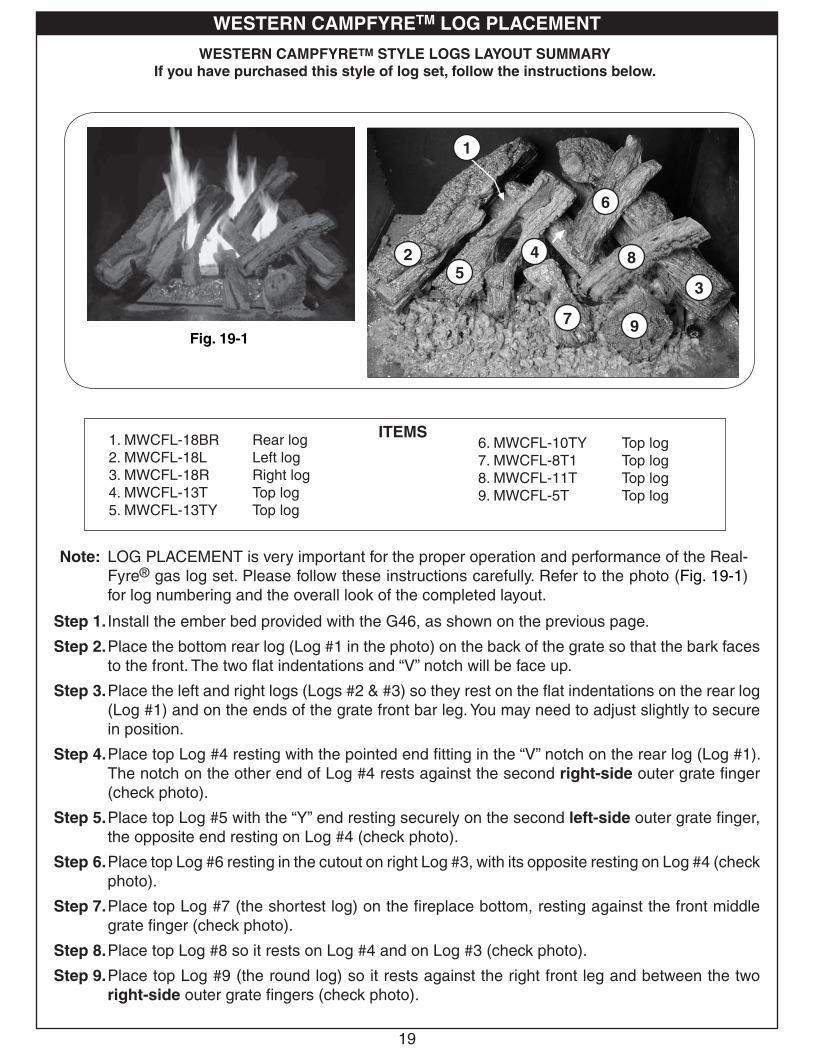
WESTERN CAMPFYRETM STYLE LOGS LAYOUT SUMMARYIf you have purchased this style of log set, follow the instructions below.
Note: LOG PLACEMENT is very important for the proper operation and performance of the Real-Fyre® gas log set. Please follow these instructions carefully. Refer to the photo (Fig. 19-1) for log numbering and the overall look of the completed layout.
Step 1. Install the ember bed provided with the G46, as shown on the previous page.
Step 2. Place the bottom rear log (Log #1 in the photo) on the back of the grate so that the bark faces to the front. The two fl at indentations and “V” notch will be face up.
Step 3. Place the left and right logs (Logs #2 & #3) so they rest on the fl at indentations on the rear log (Log #1) and on the ends of the grate front bar leg. You may need to adjust slightly to secure in position.
Step 4. Place top Log #4 resting with the pointed end fi tting in the “V” notch on the rear log (Log #1). The notch on the other end of Log #4 rests against the second right-side outer grate fi nger (check photo).
Step 5. Place top Log #5 with the “Y” end resting securely on the second left-side outer grate fi nger, the opposite end resting on Log #4 (check photo).
Step 6. Place top Log #6 resting in the cutout on right Log #3, with its opposite resting on Log #4 (check photo).
Step 7. Place top Log #7 (the shortest log) on the fi replace bottom, resting against the front middle grate fi nger (check photo).
Step 8. Place top Log #8 so it rests on Log #4 and on Log #3 (check photo).
Step 9. Place top Log #9 (the round log) so it rests against the right front leg and between the two right-side outer grate fi ngers (check photo).
1. MWCFL-18BR Rear log2. MWCFL-18L Left log3. MWCFL-18R Right log4. MWCFL-13T Top log5. MWCFL-13TY Top log
6. MWCFL-10TY Top log7. MWCFL-8T1 Top log8. MWCFL-11T Top log9. MWCFL-5T Top log
ITEMS
Fig. 19-1
WESTERN CAMPFYRETM LOG PLACEMENT
1
25
4
7
6
8
3
9

20
1. Tournez le cadran dans le sens des aiguilles d’une montre à OFF seulement quand l ’arrêt complet est nécessaire.
Fig. 20-11. S’ALLUMER - tournez le bouton de commande de brûleur à OFF
et attendez 5 minutes avant de s’allumer.
2. Tournez le cadran dans le sens contraire des aiguilles d’une montre
à la position PILOT. Avec le bouton prêt de pression d’allumette dedans et la prise pendant 60 secondes tout en allumant le pilote.
3. Tournez le bouton contre- dans le sens des aiguilles d’une montre à ON au brûleur léger.
����� �����
��
� ��
�����
���
��
���
��
���
��
����
�
Le Vrai-Fyre système de brûleur a un pilote qui peut être allumé à la main en utilisant une allumette ou un allumeur. En allumant le pilote, suivez ces instructions exactement. AVANT DE S’ALLUMER, sentez tous autour du secteur de brûleur pour le gaz. Soyez sûr de sentir à côté du plancher car un certain gaz est plus lourd que l’air et arrangerez sur le plancher. SI VOUS SENTEZ LE GAZ, SUIVEZ LES INSTRUCTIONS À LA P. 1. Utilisez seulement votre main pour enfoncer ou pour tourner le bouton de commande de gaz. N’utilisez jamais les outils. Si le bouton n’enfoncera pas ou ne tournera pas à la main, n’essayez pas de le réparer. Appelez un technicien de service professionnel qualifi é et. La force ou la réparation essayée peut avoir comme conséquence l’incendie ou l’explosion.
AVERTISSEMENT: Si vous ne suivez pas ces instructions exactement, une incendie ou une explosion peut résulter entraînant des dégats matériels, des blessures ou la perte de la vie.
N’employez pas cet appareil si n’importe quelle partie a été sous-marine. Réclamez immédiatement un technicien de service professionnel qualifi é et pour inspecter l’appareil et pour remplacer n’importe quelle partie du système de
commande et de n’importe quelle commande de gaz qui a été sous l’eau.
POUR VOTRE SÛRETÉ, LISEZ AVANT DE S’ALLUMER
ALLUMER LE PILOTE
1. Si le bouton de soupape de commande de brûleur n’est pas dans la position de OFF, enfoncez la poignée de commande de gaz légèrement et tournez-vous dans le sens des aiguilles d’une montre vers OFF (fi g. 20-1).
Note: Le bouton de commande de brûleur ne peut pas être tourné du PILOT au OFF à moins que la poignée soit enfoncée légèrement. Ne forcez pas.
Attendez cinq minutes pour dégager dehors n’importe quel gaz. Si vous sentez alors le gaz, ARRÊTEZ ! Informez votre fournisseur de gaz ou le département de feu immédiatement. Si vous ne sentez pas le gaz, passez dessus à l’étape 2.
2. Tournez le bouton de commande de brûleur dans le sens contraire des aiguilles d’une montre au PILOT (fi g. 20-1). Poussez la poignée de commande toute la manière dedans et tenez-la. Tenez une longue allumette de cheminée ou un proche plus léger le thermocouple pour allumer le pilote. Continuez à tenir le bouton de commande pour approximativement 30 secondes après que le pilote est allumé pour permettre au thermocouple de détecter la fl amme pilote, puis libérez le bouton. Le pilote restera s’est allumé.
• Si le pilote ne s’allumera pas, répétez les étapes 1. et 2.
• Si le pilote ne restera pas s’allumait après que plusieurs essais, tournent la poignée de commande de gaz à OFF et appellent votre fournisseur de technicien ou de gaz de service.
ALLUMAGE DU BRÛLEUR PRINCIPAL
1. Assurez-vous que le pilote brûle.
2. Tournez la poignée de commande de gaz dans le sens contraire des aiguilles d’une montre à ON (fi g. 20-1) pour mettre à feu le brûleur. Le brûleur mettra à feu.
Note: Examinez périodiquement la flamme pilote pour assurer le modèle approprié de fl amme (Fig. 20-1).
ASSUREZ-VOUS QUE LE THERMOCOUPLE ET L’ASSEMBLÉE PILOTE SONT EN ALIGNEMENT CORRECT AVEC L’UN L’AUTRE (FIG. 20-1).
ROTATION OUTRE DU BRÛLEUR PRINCIPAL
1. De la position de ON, tournez le bouton de commande dans le sens des aiguilles d’une montre à la position PILOT. Le brûleur s’éteindra et le pilote restera s’est allumé.
S’ÉTEINDRE LE PILOTE1. Si complet l’arrêt est désiré, de la position PILOT,
de l’enfoncer le bouton de commande légèrement et du tour dans le sens des aiguilles d’une montre
à la position de repos. Ne forcez pas le bouton. NE FORCEZ PAS LE BOUTON. Ceci exigera du pilote d’être re-s’est allumé avant d’utiliser le brûleur encore.
Thermocouple
INSTRUCTIONS D’ÉCLAIRAGE - PILOTE ET VALVE MANUELS DE LA SÉRIE 17
Le SPK-17 est capable de l’éclairage à distance. Si votre unité est équipée d’un extérieur, lisez et suivez les instructions à distance séparées d’actionner le brûleur à distance.
(valve manuelle montrée)
Le Vrai-Fyre® système de brûleur a un pilote qui peut être allumé en utilisant construit dans le passage d’ignitor de piezo sur le brûleur, ou employer à la main une allumette ou désirer ardemment allumeur étranglé. En allumant le pilote, suivez ces instructions exactement.
2. Tournez le bouton de commande de brûleur dans le sens contraire des aiguilles d’une montre au PILOT(Fig. 20-1). Poussez la poignée de commande toute la manière dedans et tenez-la. Enfoncez le bouton d’ignitor de piezo plusieurs fois jusqu’aux lampes témoin. Continuez à tenir le bouton de commande pour approximativement 30 secondes après que le pilote est allumé pour permettre au thermocouple de détecter la fl amme pilote, puis libérez le bouton. Le pilote restera s’est allumé.

The Real-Fyre® burner system has a pilot that can be lit by hand using a match or lighter. When lighting the pilot, follow these instructions exactly.
BEFORE LIGHTING, smell all around the burner area for gas. Be sure to smell next to the fl oor, as some gas is heavier than air and will settle on the fl oor. IF YOU SMELL GAS, FOLLOW THE INSTRUCTIONS ON P. 1.
Use only your hand to push in or turn the gas control knob. Never use tools. If the knob will not push in or turn by hand, don't try to repair it. Call a qualifi ed professional service technician. Force or attempted repair may result in fi re or explosion.
WARNINGIf you do not follow these instructions exactly, a fi re or explosion may result, causing property
damage, personal injury, or loss of life.
Do not use this appliance if any part has been underwater. Immediately call for a qualifi ed professional service technician to inspect the appliance and to replace any part of the control system and any gas control that has been underwater.
FOR YOUR SAFETY, READ BEFORE LIGHTING
LIGHTING THE PILOT
1. If the burner control valve knob is not in the OFF position, push in the gas control handle slightly and turn clockwise to OFF (Fig. 21-1). Refer to the PARTS LIST for the location of the burner control valve knob.
Note: The burner control knob cannot be turned from PILOT to OFF unless the handle is pushed in slightly. Do not force.
Wait fi ve minutes to clear out any gas. If you then smell gas, STOP! Notify your gas supplier or the fi re department immediately. If you don’t smell gas, go on to step 2.
2. Turn the burner control knob counter-clockwise to PILOT (Fig. 21-1). Push the control
handle all the way in and hold it. Hold a long fi replace match or lighter near the thermocouple to light the pilot. Continue to hold the control knob for approximately 30 seconds after the pilot is lit to allow the thermocouple to detect the pilot fl ame, then release the knob. The pilot will remain lit.
• If the pilot will not light, repeat steps 1 and 2.
• If the pilot will not stay lit after several tries, turn the gas control handle to OFF and call your service technician or gas supplier.
IGNITING THE MAIN BURNER
1. Make sure the pilot is burning.
2. Turn the gas control handle counterclockwise to ON (Fig. 21-1) to ignite the burner. The
burner will ignite.
Note: Periodically check the pilot fl ame for the proper fl ame pattern (Fig. 21-1).
MAKE SURE THE THERMOCOUPLE AND PILOT ASSEMBLY ARE IN CORRECT ALIGNMENT WITH EACH OTHER (Fig. 21-1).
TURNING OFF THE MAIN BURNER
1. From the ON position, turn the control knob clockwise to the PILOT position. The burner will extinguish, and the pilot will remain lit.
EXTINGUISHING THE PILOT
1. If complete shutdown is desired, from the PILOT position, push in the control knob slightly and turn clockwise to the OFF position. Do not force the knob. This will require the pilot to be relit before using the burner again.
21
1. Turn the knob c l o ck w i s e t o OFF only when complete s h u t d o w n i s desired.Fig. 21-1
1. Lighting -Turn the burner control knob to OFF and wait 5 minutes before lighting.
2. Turn knob counterclockwise to PILOT position. With match ready, press knob in and hold for 60 seconds while lighting pilot.
3. Turn the knob counterclockwise to ON to light the burner.
����� �����
��
� ��
�����
���
��
���
��
���
��
����
�
Thermocouple
LIGHTING INSTRUCTIONS - MANUAL PILOT AND SERIES 17 VALVE
The SPK-17 is capable of remote lighting. If this unit was shipped with a remote, or if a remote system was installed later, read and follow the separate remote instructions to operate the burner remotely.
(Manual valve shown)
The Real-Fyre® burner system has a pilot that can be lit using the built-in piezo ignitor switch on the burner, or by hand using a match or long-necked lighter. When lighting the pilot, follow these instructions exactly.
2. Turn the burner control knob counterclockwise to PILOT (Fig. 21-1). Push the control
handle all the way in and hold it. Push in the piezo ignitor button several times until the pilot lights. Continue to hold the control knob for approximately 60 seconds after the pilot is lit to allow the thermocouple to detect the pilot fl ame, then release the knob. The pilot will remain lit.

22
AJUSTANT LE PILOTE1. La fl amme pilote devrait encercler le bout de générateur,
et est préréglée à l’usine (Fig. 22-2).
2. Si l’ajustement est nécessaire, (Fig. 22-1) tournez la vis d’approche de gaz dans le sens contraire des aiguilles d’une montre pour augmenter la fl amme pilote, ou pour diminuer dans le sens des aiguilles d’une montre
la fl amme pilote.
ENTRETIENVotre brûleur à casserole est équipé d’un pilote de sûreté qui coupera l’offre de gaz au cas où le pilote serait ne brûlant pas ou ne fonctionnant pas correctement. Assurez-vous que le pilote est ajusté correctement et que les agrafes de cosse de générateur sont étroitement reliées aux vis terminales sur la valve. Si le pilote ne restera pas allumait, appelle votre utilité de gaz ou fournisseur locale de gaz.
Un contrôle périodique du suivant devrait être exécuté au moins annuellement par un représentant qualifi é de service professionnel.
1. Valves et commande d’interrupteur à levier pour l’opération appropriée.
2. Système de conduite de cheminée pour la rouille, les dommages ou les fuites.
3. Une opération plus humide.
4. Orifi ces pour la saleté ou d’autres corps étrangers.
5. Contrôle visuel sur le brûleur.
Si cette unité était embarquée avec un extérieur, ou si un système à distance était installé plus tard, lisez et suivez les instructions à distance séparées d’actionner le brûleur à distance.
ALLUMANT LE PILOTE
Pour lire le bouton de commande de soupape de sûreté (Fig. 22-1) lisez l’indicateur formé par larme la plus proche en métal d’inscription.
1. Si le bouton de commande de soupape de sûreté est en position PILOT, enfoncez légèrement sur le bouton et tournez-le dans le sens des aiguilles d’une montre
jusqu à la position de OFF.
2. Libérez le bouton et attendez cinq minutes.
3. Tournez le bouton de soupape de sûreté dans le sens contraire des aiguilles d’une montre à la position PILOT (seulement le gaz pilote coulera quand le bouton est enfoncé).
4. Placez une longue allumette ou un allumeur de butane au brûleur pilote et en même temps, poussent le bouton de soupape de sûreté entièrement dedans. Le pilote s’allumera.
5. Tenez le bouton de soupape de sûreté dedans pendant approximativement 60 secondes avant de libérer.
6. Si le pilote ne reste pas s’allumait, la position de OFF de bouton de soupape de sûreté dans le sens des aiguilles d’une montre entièrement. Attendez cinq minutes, puis répétez les étapes 3. à 5.
METTANT À FEU LE BRÛLEUR PRINCIPAL
Avec lampe témoin, tournent le bouton de soupape de sûreté dans le sens contraire des aiguilles d’une montre à la position de ON. Commutez la commande d’interrupteur à levier à la position de ON et le brûleur s’allumera.
COUPANT LE BRÛLEUR PRINCIPAL
Commutez la commande d’interrupteur à levier à la position de OFF. Le pilote restera s’est allumé.
COUPANT LE PILOTESoyez sûr que commande d’interrupteur à levier est éteint et enfonce et tourne le bouton de soupape de sûreté dans le sens des aiguilles d’une montre à la position de OFF.
IN
THTPTH
TP
INO
UT
Fig. 22-1
AVERTISSEMENT : Si vous ne suivez pas ces instructions exactement, une incendie ou une explosion peut résulter entraînant des dégats matériels, des blessures ou la perte de la vie.
N’employez pas cet appareil si n’importe quelle partie a été sous-marine. Réclamez immédiatement un technicien de service professionnel qualifi é et pour inspecter l’appareil et pour remplacer n’importe quelle partie du système de
commande et de n’importe quelle commande de gaz qui a été sous l’eau.
POUR VOTRE SÛRETÉ, LISEZ AVANT DE S’ALLUMER
INTERRUPTEUR À LEVIERINTERRUPTEUR À LEVIER
HARNAIS DE CÂBLAGE
VIS PILOTE DE CAP
BOUTON DE
COMMANDE
DE VALVE
DE SAFTEY
PORT PILOTE DE GAZ
INSTRUCTIONS D’ÉCLAIRAGE - VALVE DE LA SÉRIE 11
Le Vrai-Fyre système de brûleur a un pilote qui peut être allumé à la main en utilisant une allumette ou un allumeur. En allumant le pilote, suivez ces instructions exactement. AVANT DE S’ALLUMER, sentez tous autour du secteur de brûleur pour le gaz. Soyez sûr de sentir à côté du plancher car un certain gaz est plus lourd que l’air et arrangerez sur le plancher. SI VOUS SENTEZ LE GAZ, SUIVEZ LES INSTRUCTIONS À LA P. 1. Utilisez seulement votre main pour enfoncer ou pour tourner le bouton de commande de gaz. N’utilisez jamais les outils. Si le bouton n’enfoncera pas ou ne tournera pas à la main, n’essayez pas de le réparer. Appelez un technicien de service professionnel qualifi é et. La force ou la réparation essayée peut avoir comme conséquence l’incendie ou l’explosion.
Note: La fl amme pilote devrait encercler le dessus du générateur
Fig. 22-2Generator
Pilot
Le Vrai-Fyre® système de brûleur a un pilote qui peut être allumé en employant construit dans le passage d’ignitor de piezo sur le brûleur, ou employer à la main une allumette ou désirer ardemment allumeur étranglé. En allumant le pilote, suivez ces instructions exactement.
4. Poussez et tenez le bouton de soupape de sûreté entièrement dedans et enfoncez le bouton d’ignitor de piezo plusieurs fois jusqu’aux lampes témoin.
IN
THTPTH
TP
INO
UT
Fig. 22-1
INTERRUPTEUR À LEVIERINTERRUPTEUR À LEVIER
HARNAIS DE CÂBLAGE
VIS PILOTE
BOUTON DE
COMMANDE
DE VALVE
DE SAFTEY
PORT PILOTE DE GAZ
Generator
Pilot
Electrode

ADJUSTING THE PILOTa. The pilot fl ame should encircle the generator tip,
and is preset at the factory (Fig. 23-2).
b. If adjustment is necessary (Fig.23-1), turn the gas adjustment screw counterclockwise to increase the pilot fl ame, or clockwise to decrease the pilot fl ame.
MAINTENANCEYour pan burner is equipped with a safety pilot that will shut off the gas supply in the event that the pilot is not functioning properly. Make sure the pilot is adjusted properly and that the generator spade clips are tightly connected to the terminal screws on the valve. If the pilot will not stay lit, call your local gas utility or gas supplier.
A periodic check of the following should be performed at least annually by a qualifi ed professional service representative:
1. Valves and toggle switch control for proper operation.
2. Flue system for rust, damage, or leaks.
3. Damper operation.
4. Orifi ces for dirt or other foreign matter.
5. Visual check on the burner.
If this unit was shipped with a remote, or if a remote system was installed later, read and follow the separate remote instructions to operate the burner remotely.
WARNINGIf you do not follow these instructions exactly, a fi re or explosion may result, causing property
damage, personal injury, or loss of life.
Do not use this appliance if any part has been underwater. Immediately call for a qualifi ed professional service technician to inspect the appliance and to replace any part of the control system and any gas control that has been underwater.
FOR YOUR SAFETY, READ BEFORE LIGHTING
LIGHTING THE PILOTTo read the safety valve control knob (Fig. 23-1), read the marking nearest the teardrop-shaped metal pointer.
1. If the safety valve control knob is in the PILOT position, push in slightly on the knob and rotate it clockwise to the OFF position.
2. Release knob and wait fi ve (5) minutes.
3. Turn safety valve knob counterclockwise to the PILOT position. (Only the pilot gas will fl ow when the knob is pushed in.)
4. Place a long match or a butane lighter at the pilot burner, and at the same time, push the safety valve knob fully in. The pilot will light.
5. Hold the safety valve knob in for approximately 60 seconds before releasing.
6. If the pilot does not stay lit, turn the safety valve knob clockwise to the full OFF position. Wait fi ve (5) minutes, then repeat steps 3 through 5.
IGNITING THE MAIN BURNERWith the pilot lit, turn the safety valve knob counterclockwise
to the ON position. Switch the toggle switch control to the ON position, and the burner will light. Refer to the PARTS LIST for the toggle switch location.
SHUTTING OFF THE MAIN BURNERSwitch the toggle switch control to the OFF position. The pilot will remain lit.
SHUTTING OFF THE PILOTBe sure the toggle switch control is OFF and depress and turn the safety valve knob clockwise to the OFF position.
Fig. 23-1
Wiring harness
Toggle switch
Pilot screw Pilot gas port
control knob
Safety valve
IN
THTPTH
TP
INO
UT
23
LIGHTING INSTRUCTIONS - SERIES 11 VALVE
The Real-Fyre® burner system has a pilot that can be lit by hand using a match or lighter. When lighting the pilot, follow these instructions exactly.
BEFORE LIGHTING, smell all around the burner area for gas. Be sure to smell next to the fl oor, as some gas is heavier than air and will settle on the fl oor. IF YOU SMELL GAS, FOLLOW THE INSTRUCTIONS ON P. 1.
Use only your hand to push in or turn the gas control knob. Never use tools. If the knob will not push in or turn by hand, don't try to repair it. Call a qualifi ed professional service technician. Force or attempted repair may result in fi re or explosion.
Generator
Pilot
Note: Pilot fl ame should encircle top of the generator.Fig. 23-2 Lighting the pilot
The Real-Fyre® burner system has a pilot that can be lit by using the built-in piezo ignitor switch on the burner, or by hand using a match or long-necked lighter. When lighting the pilot, follow these instructions exactly.
4. Push and hold the safety valve knob fully in and push in the piezo ignitor button several times until the pilot lights.
Fig. 23-1
Wiring harness
Toggle switch
Pilot screw Pilot gas port
control knob
Safety valve
IN
THTPTH
TP
INO
UT
Generator
PilotElectrode

24
COMMUTATEUR DU CÔNE DU PIN DANS SUR
POSITION
CETTE UNITÉ (G46-01) A UN PILOTE DE LA NON-POSITION.
Allumer le brûleur pilote et principal.
1. ARRÊTEZ! Lisez l'information de la sécurité au-dessus.
2. Tour "FERMÉ" tout appareil électrique (tel que le Peterson système du circulator de l'air chaud) si usagé avec l'ensemble de la grosse bûche.
3. Placez le 'Changement' (a marqué " je" = allumez; "O" = "Fermé", Représentez-en 24-1) dans "FERMÉ" place.
4. Attendez cinq (5) minutes éclaircir dehors tout gaz. Si vous alors gaz de l'odeur, ARRÊT! Suivez les directives sur page 1.
5. Pressez le changement sur le cône du pin au "je" place ("je" = Allumez, voyez le Chiffre 24-2). Une série rapide d'étincelles au pilote (cobra) tête. Ces étincelles cessent quand la fl amme pilote est allumée et est logée dans une sécurie. Quand le pilote devient stable la valve électronique ouvrira et allumer le brûleur principal.
POUR VOTRE SECURITE, LISEZ AVANT D’ALLUMER
PRÉVENIR: Si vous ne suivez pas ces instrucions exactement, un feu ou explosion peuvent résulter, en causant dégât de la propriété, blessure personnelle ou perte de vie.
* Nous recommandons qu’avant que vous installiez votre grosse bûche mise vous vous familiarisez avec la disposition de la valve du contrôle. Cela vous aidera pour être opérer plus confi ant la grosse bûche mise quand a complètement installé.
Fig. 24-2 Fig. 24-3
COMMUTATEUR DU CÔNE DU PIN DANS 'FERMÉ'
POSITION
Le l’ensemble de la grosse bûche du gaz a un pilote qui doit être allumé à la main. Quand allumer le pilote, suivez ces directives exactement
AVANT d’ALLUMER, sentez autour de la grosse bûche du gaz mis la région pour le gaz. Soyez sûr de sentir à côté du sol parce qu’un peu de gaz est plus lourd qu’air et résoudra par terre. SI VOUS SENTEZ DU GAZ, SUIVEZ LES DIRECTIVES SUR pAGE 1.
Utilisez seulement votre main pousser dans ou tourner le bouton de réglage du gaz. N’utilisez jamais des outils. Si le bouton ne poussera pas dans ou tourner à la main, n’essayez pas de le réparer. Appelez un technicien du service quali-fi é, professionnel. force ou a tenté la réparation peut résulter en feu ou explosion.
INSTRUCTIONS D’ÉCLAIRAGE - VALVE DE LA SÉRIE 01
PINE CONE SWITCHFig. 24-1
PRUDENCE: SI L'ENSEMBLE du GAZ N'ALLUME PAS DANS 20 SECONDES, ARRÊTEZ, ATTENDEZ ALORS 5 MINUTES RÉPÉTITION "ALLUMER LE BRÛLEUR PILOTE ET PRINCIPAL".
ÉTEINDRE LE G46-01 ENSEMBLE DE LA GROSSE BÛCHE DU GAZ ÉLOIGÉ
1. Pressez le changement sur le cône du pin au O place (O = FERMÉ, Représentez-en 24-3). Le courant du gaz cessera et toutes les fl ammes (brûleur principal et pilote) sortira.
Si cette unité était embarquée avec un extérieur, ou si un système à distance était installé plus tard, lisez et suivez les instructions à distance séparées d’actionner le brûleur à distance.

25
* We recommend that before you install your log set, you familiarize yourself with the control valve layout. This will help you to be confi dent operating the log set when fully installed.
WARNING
If you do not follow these instructions exactly, a fi re or explosion may result, causing property damage, personal injury, or loss of life.
TO LIGHT THE PILOT AND MAIN BURNER
1. STOP! Read the safety information above.
2. Turn OFF any electrical appliance (such as the Peterson warm air circulator system) if used with the log set.
3. Place the switch (marked I = IGNITE; O = OFF, Fig. 25-1) in the OFF position.
4. Wait fi ve (5) minutes to clear out any gas. If you then smell gas, STOP! Follow the instructions on page 1.
5. Press the switch on top of the pine cone to the I position (see Fig. 25-2). There will be a rapid series of sparks at the pilot (cobra) head. These sparks cease when the pilot fl ame is lit and stable. When the pilot becomes stable, the electronic valve will open and light the main burner.
CAUTION: If the gas set does not ignite within 20 seconds, stop, wait 5 minutes, and then repeat TO LIGHT THE PILOT AND MAIN BURNER.
LIGHTING INSTRUCTIONS - 01 VALVE
THIS UNIT (G46-01) HAS A NON-STANDING PILOT.
TO TURN OFF THE G46-01 REMOTE GAS LOG SET
1. Press the switch on top of the pine cone to the O position (O = OFF, Fig. 25-3). The gas fl ow will cease, and all fl ames (main burner and pilot) will go out.
If this unit was shipped with a remote, or if a remote system was installed later, read and follow the separate remote instructions to operate the burner remotely.
Pine cone switch
Fig. 25-1 Fig. 25-2 Fig. 25-3
Pine cone switch in ON position
Pine cone switch in OFF position
FOR YOUR SAFETY, READ BEFORE LIGHTING
The Real-Fyre® G46 Series gas log set has a pilot that can be lit by hand using the piezo ignitor. When lighting the pilot, follow these instructions exactly.
BEFORE LIGHTING, smell all around the gas log set area for gas. Be sure to smell next to the fl oor as some gas is heavier than air and will settle on the fl oor. IF YOU SMELL GAS, FOLLOW THE INSTRUCTIONS ON PAGE 1.
Use only your hand to push in or turn the gas control knob. Never use tools. If the knob will not push in or turn by hand, don't try to repair it. Call a qualifi ed professional service technician. Force or attempted repair may result in fi re or explosion.

26
AVERTISSEMENT : Si vous ne suivez pas ces instructions exactement, une incendie ou une explosion peut résulter entraînant des dégats matériels, des blessures ou la perte de la vie.
INSTRUCTIONS D’ÉCLAIRAGE - VALVE DE LA SÉRIE 15
N’employez pas cet appareil si n’importe quelle partie a été sous-marine. Réclamez immédiatement un technicien de service professionnel qualifi é et pour inspecter l’appareil et pour remplacer n’importe quelle partie du système de
commande et de n’importe quelle commande de gaz qui a été sous l’eau.
POSITIONS D’OPÉRATION DE CLAPET À GAZ
OFF IGNITION PILOT ON
Fig. 26-1
BOUTON DE COMMANDE DE TAILLE DE FLAMME
Fig. 26-4
Fig. 26-3
ALLUMER LE PILOTE1. Tournez le bouton de commande d’Ignitor (Fig. 26-1) de la
soupape de commande de brûleur au côté de la casserole de brûleur dans le sens contraire des aiguilles d’une montre de sorte que la partie de rétrécissement du bouton se déplace de la position de OFF, légèrement vers IGN jusqu’à atteindre l’arrêt.
2. Serrez le bouton de commande d’ignitor dedans et tenez dedans pendant 5 secondes (seulement le gaz pilote coulera).
3. Continuez d’enfoncer tout en tournant le dans le sens contraire des aiguilles d’une montre supplémentaire de bouton de commande d’ignitor, vers la position PILOT, jusqu’à ce que vous entendiez un clic. Le clic est une indication que l’ignitor de pizio a été activé.
Note: Si l’étincelle de l’ignitor de pizio n’allume pas le pilote, répétez les étapes 2 et 3 jusqu’au pilote lights.
4. Continuez à tenir le bouton de commande d’ignitor en position PILOT pour 60 secondes après que le pilote a été allumé pour permettre au thermocouple de détecter la fl amme pilote.
Note: La fl amme pilote devrait toujours être présent quand le système de brûleur est en fonction, et devrait juste envelopper le bout du thermocouple.
ALLUMAGE DU BRÛLEUR PRINCIPAL1. Quand la flamme pilote est stable, libérez le bouton de
commande d’ignitor et tournez-vous dans le sens contraire des aiguilles d’une montre vers la position de ON pour permettre le brûleur principal.
2. Tournez le bouton de commande de taille de fl amme (Fig. 26-3) entièrement dans le sens contraire des aiguilles d’une montre pleinement la position de fonctionnement (Fig. 26-4) pour mettre à feu le brûleur chez BTUs maximum.
Après que le brûleur principal mette à feu, ajustez la taille de fl amme comme indiqué ci-dessous.
AJUSTEMENT DE LA TAILLE DE FLAMMET1. Pour ajuster la fl amme, tournez le bouton de commande de taille
de fl amme (Fig. 26-3) dans le sens contraire des aiguilles d’une montre à la taille de fl amme d’augmentation et dans le sens des aiguilles d’une montre à la taille de fl amme de diminution jusqu’à ce que les fl ammes aient les caractéristiques désirées.
2. Quand vous êtes fi ni appréciant votre feu, tournez le bouton de commande de taille de fl amme à OFF. Le pilote restera s’est allumé. Le système de brûleur peut être relit en tournant le bouton de commande de taille de fl amme vers ON.
COUPER LE PILOTESi vous ne projetez pas sur employer votre système de brûleur pendant une période prolongée vous pouvez choisir de vous éteindre le pilote. Pour faire ceci, tournez le bouton de commande de taille de fl amme jusqu à la position de OFF et puis tournez le bouton de commande d’ignitor jusqu à la position de OFF (Fig. 26-1).
Important: En fermant le système de brû leur complètement, tournez le bouton de control/ignition à la position de repos (Fig. 26-1). Si vous désirez tourner l’unité en arrière dessus, attendez une minute au minimum avant de commencer le procédé de rallumer (ALLUMANT LE PILOTE). Ceci permet à la soupape de sûreté de remettre à zéro en vue de rallumer.
Si cette unité était embarquée avec un extérieur, ou si un système à distance était installé plus tard, lisez et suivez les instructions à distance séparées d’actionner le brûleur à distance.
POUR VOTRE SÛRETÉ, LISEZ AVANT DE S’ALLUMER
BOUTON DE COMMANDE/ D’ALLUMAGE
BOUTON DE COMMANDE
DE TAILLE DE FLAMME
OFF ON
Fig. 26-2
Thermocouple
Le Vrai-Fyre® système de brûleur a un pilote qui peut être allumé à la main en utilisant une allumette ou un allumeur. En allumant le pilote, suivez ces instructions exactement. AVANT DE S’ALLUMER, sentez tous autour du secteur de brûleur pour le gaz. Soyez sûr de sentir à côté du plancher car un certain gaz est plus lourd que l’air et arrangerez sur le plancher. SI VOUS SENTEZ LE GAZ, SUIVEZ LES INSTRUCTIONS À LA P. 1. Utilisez seulement votre main pour enfoncer ou pour tourner le bouton de commande de gaz. N’utilisez jamais les outils. Si le bouton n’enfoncera pas ou ne tournera pas à la main, n’essayez pas de le réparer. Appelez un technicien de service professionnel qualifi é et. La force ou la réparation essayée peut avoir comme conséquence l’incendie ou l’explosion.
Fig. 26-2
Thermocouple

WARNINGIf you do not follow these instructions exactly, a fi re or explosion may result, causing property
damage, personal injury, or loss of life.
LIGHTING INSTRUCTIONS - SERIES 15 VALVE
Do not use this appliance if any part has been underwater. Immediately call for a qualifi ed professional service technician to inspect the appliance and to replace any part of the control system and any gas control that has been underwater.
Gas valve operating positions
OFF IGNITION PILOT ON
Fig. 27-1
Flame-height control knob
Fig. 27-4
Fig. 27-3
LIGHTING THE PILOT1. Turn the ignitor control knob (Fig. 27-1) on the burner
control valve assembly to the side of the burner pan counterclockwise so that the narrowing part of the knob moves from the OFF position, slightly toward IGN, until reaching the stop.
2. Press the ignitor control knob in and hold in for fi ve (5) seconds (only pilot gas will fl ow).
3. Continue pressing in while turning the ignitor control knob further counterclockwise toward the PILOT position until you hear a click. The click is an indication that the piezo ignitor has been activated.
Note: If the spark from the piezo ignitor does not light the pilot, repeat steps 2 & 3 until the pilot lights.
4. Continue to hold the ignitor control knob in the PILOT position for 60 seconds after the pilot has been lit to allow the thermocouple to detect the pilot fl ame.
Note: The pilot fl ame should always be present when the burner system is in operation, and should just envelop the tip of the thermocouple.
IGNITING THE MAIN BURNER1. When the pilot fl ame is stable, release the ignitor control
knob and turn counterclockwise to the ON position to enable the main burner.
2. Turn the flame-height control knob (Fig. 27-3) counterclockwise to the fully ON position
(Fig. 27-4) to ignite the burner at maximum BTUs. After the main burner ignites, adjust the fl ame height as indicated below.
ADJUSTING THE FLAME HEIGHT1. To adjust the fl ame, turn the fl ame-height control knob
(Fig. 27-3) counterclockwise to increase the fl ame height, or clockwise to decrease the fl ame height, until the fl ames have the desired characteristics.
2. When you are fi nished enjoying your fi re, turn the fl ame-height control knob to OFF. The pilot will remain lit. The burner system can be relit by rotating the fl ame-height control knob toward ON.
SHUTTING OFF THE PILOTIf you do not plan on using your burner system for an extended period, you may elect to extinguish the pilot. To do this, rotate the fl ame-height control knob to the OFF position and then rotate the ignitor control knob to the OFF position (Fig. 27-1).
Important: When shutting the burner system down completely, turn the control/ignition knob to the OFF position (Fig. 27-1). If you desire to turn the unit back on, wait a minimum of one (1) minute before starting the relight procedure (LIGHTING THE PILOT). This allows the safety valve to reset in preparation for relighting.
If this unit was shipped with a remote, or if a remote system was installed later, read and follow the separate remote instructions to operate the burner remotely.
FOR YOUR SAFETY, READ BEFORE LIGHTING
Control/ignition knob
Flame-height control knob
OFF ON27
Fig. 27-2
Thermocouple
The Real-Fyre® burner system has a pilot. When starting the pilot, follow these instructions exactly.
BEFORE LIGHTING, smell all around the gas burner system area for gas. Be sure to smell next to the fl oor, as some gas is heavier than air and will settle on the fl oor. IF YOU SMELL GAS, FOLLOW THE INSTRUCTIONS ON P. 1.
Use only your hand to push in or turn the gas control knob. Never use tools. If the knob will not push in or turn by hand, don't try to repair it. Call a qualifi ed professional service technician. Force or attempted repair may result in fi re or explosion.
Fig. 27-2
Thermocouple

28
The pilot burner is preset at the factory and normally should not require adjustment. However, if adjustment is necessary, the following steps should be taken:
With the pilot burner lit and the control knob in the pilot position, use a long, narrow screwdriver to turn the pilot adjustment screw (located on front of valve). Turn the adjustment screw slowly clockwise to reduce the fl ame, or counterclockwise to increase the fl ame. The adjustment screw can be turned so that the pilot fl ame is completely extinguished. The pilot fl ame should be a quiet, soft blue fl ame with yellow tipping that encircles the thermocouple tip.
Turn the control knob to the ON position to ensure proper ignition of the log set.
PILOT BURNER ADJUSTMENT (G46 MANUAL)
The pilot burner is preset at the factory and should normally not require any adjustment. However, if adjustment is necessary, the following steps should be taken:1. Pull the burner forward so that you can access the
pilot burner adjustment screw. 2. Light the pilot burner (see the LIGHTING
INSTRUCTIONS).
3. With the control knob in the PILOT position, carefully remove the cap screw and gasket covering the safety pilot adjustment screw on the control valve.
4. Using a long, narrow screwdriver, turn the pilot adjustment screw (Fig. 28-2) slowly clockwise to
reduce the fl ame, or counterclockwise to increase the fl ame. The adjustment screw can be turned so that the pilot fl ame is completely extinguished. The pilot fl ame should be a quiet, soft blue fl ame with yellow tipping that encircles the tip of the thermopile (Fig. 28-3).
5. Reassemble the cap screw and gasket to the valve body, ensuring that the cap screw and gasket are fi rmly seated on the valve body. Turn the control knob to the ON position to ensure proper ignition of the log set.
PILOT BURNER ADJUSTMENT (G46-11)
Example of proper pilot burner fl ame and proper pilot/thermocouple alignment
Fig. 28-1
ThermocouplePilot adjustment
ON
OFF
PILOT
Fig. 28-2Position of pilot adjustment screw
Pilot adjustment screw
Thermocouple
Fig. 28-3Example of proper pilot burner fl ame and
proper pilot/thermopile alignment
PILOT BURNER ADJUSTMENT (G46-17)
Fig. 28-4
Pilot adjustThermocouple
The pilot burner is preset at the factory and normally should not require adjustment. However, if adjustment is necessary, the following steps should be taken:With the pilot lit and the control knob in the pilot position, use a long narrow screw driver and turn the pilot adjustment screw slowly clockwise to reduce the pilot fl ame or counter clockwise to increase the fl ame (Fig. 28-4). The adjustment screw can be turned so that the pilot fl ame is completely extinguished. Some tightening of the screw may occur during adjustment; this is normal. The pilot fl ame should be a soft blue color with slightly yellow tipping which encircles the thermocouple tip.After adjustment turn the control knob to the 'ON' position to assure proper ignition of the log burner.
Thermopile

29
To adjust the fl ame pattern, take a long-blade screwdriver or similar tool and stir the granules until the desired pattern is achieved. DO NOT REMOVE GRANULES FROM THE BURNER PAN.
FLAME PATTERN ADJUSTMENT (ALL MODELS)
Insert blade into sand and stir granules in various places until desired fl ame pattern is achieved.
Long-bladed screwdriver(or similar)
MAINTENANCE
Periodically remove the logs and examine the burner assembly. If dirty, clean with a stiff brush. Also examine the area around the pilot. Any dirt or lint in this area should be removed. This will ensure long life and trouble-free operation. An annual inspection and cleaning of the vent system (chimney and damper) by a qualifi ed agency is recommended. For safe operation and proper performance, use only Peterson Real-Fyre® parts and accessories.
Periodically observe the fl ames. Flames should be approximately 22"-24" above the fi replace fl oor, a little blue at the base mostly orange and yellow fl ames (see Fig. 19-1). The fl ames should impinge on the logs and grating as little as possible to avoid sooting the logs or the grating.

30
AVAILABLE ACCESSORIES FOR THE GAS BURNER SYSTEMThe following accessories are available for burner systems as indicated, and can be purchased separately from your local Peterson Real-Fyre® dealer. Before purchasing, make sure the accessory you desire is compatible with your specifi c model (for example, VR-2A is used with the Series 15 systems). To install and operate any accessory, simply follow the instructions supplied with your accessory kit.
Note: Photos not to scale
FOR SERIES 15: WS-3 WALL SWITCHTHE WS-3 SWITCH OPERATES FLAME-HEIGHT CONTROL KNOB ON SERIES 15 VALVES
FOR SERIES 15: REMOTE TRANSMITTERS AND RECEIVERSFOR VARIABLE FLAME-HEIGHT CONTROL
(FOR USE WITH SERIES 15 VALVES) AND FOR NATURAL OR PROPANE GAS
VR-1A
Transmitter handset, receiver, handset holder, and wiring
RVF-1
Transmitter handset, receiver, and wiring
Switch to valve wiring
Wall switch cover
Cover screws
Battery holder
VR-2A
Transmitter handset, receiver, handset holder, wall switch, and wiring
FOR SERIES 16: WS-4 WALL SWITCH
Switch to valve wiring
Wall switch cover
Cover screws
Battery holder
Press OFF to extinguish the main burner.
Press ON to ignite the main
burner.
THE WS-4 SWITCH OPERATES THE FLAME-HEIGHT CONTROL KNOB
Press HI/ON to turn unit on or increase fl ame height.
= =
Flame-height control knob wi l l ro ta te counterclockwise.
Press LOW/OFF to decrease fl ame height or turn unit off.
Flame-height control knob w i l l ro ta te clockwise.

31
AVAILABLE ACCESSORIES FOR THE GAS BURNER SYSTEM (Cont.)
FOR SERIES 01, 10, 11, and 12: WS-1 AND WS-2 WALL SWITCHESWS-1 SWITCH: CONTROLS BURNER SYSTEM LIGHTING AND SHUTDOWNWS-2 TIMER WALL SWITCH: CONTROLS OPERATING TIME (UP TO 60 MIN.)
PC-105/PC-106 PINE CONE REMOTE
BATTERY-OPERATED REMOTE LIGHTING SYSTEM WITH DECORATIVEPINE CONE RECEIVER FOR USE WITH NATURAL OR PROPANE GAS
RUS-1
FOR SERIES 01, 10, 11, and 12: ON/OFF REMOTES AND RECEIVERSBATTERY-OPERATED REMOTE LIGHTING SYSTEMS FOR USE WITH
NATURAL OR PROPANE GAS
Transmitter handset, receiver.
RR-2A
Transmitter handset, receiver,handset holder, wall switch, and wiring.
Mechanical timer (WS-2)Wall switch (WS-1)
PC-105 Remote transmitter(for use with Series 01,
10, 11, and 12),, ,, ))
Pine cone receiver
PC-106 Remote transmitter(for use with Series 16)
RR-2A
Transmitter handset, receiver, handset holder, wall switch, and wiring
RR-1A
Transmitter handset, receiver, wall switch, and wiring
RUS-1
Transmitter handset, receiver

32
PETERSON VENTED GAS LOG SETSLIMITED WARRANTY
All Peterson gas logs are WARRANTED for as long as you own them (lifetime).All Peterson burner assemblies are WARRANTED for TEN (10) YEARS.SPK-26 controls are covered by a THREE (3) YEAR “All Parts” Warranty.All other Peterson valves, pilots, and controls are covered by a ONE (1) YEAR Limited Warranty (excluding batteries).
This warranty applies only to the original purchaser from the date of purchase, and to Peterson products purchased for residential purposes.This warranty does not cover parts becoming defective by misuse, accidental damage, electrical damage, improper handling, and/or installation or service (log sets must be installed as outlined in the enclosed instructions by a qualifi ed professional installer and with only Peterson parts, control valves, remotes, and accessories). It does not cover labor or labor-related charges. It specifi cally excludes liability for indirect, incidental, or consequential damages. Some states do not allow the exclusion or limitation of incidental or consequential damages, so the above exclusion or limitation may not apply to you. This warranty gives you specifi ed legal rights, and you may have other rights that may vary from state to state.
For additional information regarding this warranty, or information on how to place a warranty claim, contact your Peterson dealer or the Robert H. Peterson Company.
Robert H. Peterson Co. • 14724 East Proctor Avenue • City of Industry, CA 91746
WARRANTY
FOR USE IN THE COMMONWEALTH OF MASSACHUSETTS
INSTALLATION OF THIS APPLIANCE MUST BE PERFORMED BY A
MASSACHUSETTS LICENSED PLUMBER OR GAS FITTER ONLY.
CONNECTOR KITS USED FOR INSTALLATION AND OPERATION OF THIS APPLIANCE MUST NOT BE MORE THAN 36" IN LENGTH.
FIREPLACE DAMPER MUST BE REMOVED OR PERMANENTLY FIXED/WELDED IN FULL OPEN POSITION PRIOR TO
INSTALLING THIS PRODUCT.
ROBERT H. PETERSON CO.Quality Check Date:___________
Orifi ce # (Main):__________Orifi ce # (Other):__________ Model #: ___________Leak Test: ___________ Serial #: ___________Burn Test: ___________ Air Shutter: ___________Gas Type: NAT. / PROPANE Inspector: ___________