Embed Size (px)
DESCRIPTION
Soft
Citation preview

RoadRunner Quick Guide
May, 2005 System 1200 This guide describes how to export road jobs from Microstation to use with RoadRunner.

RoadRunner Quick Guide May, 2005 Page 2/37
RoadRunner Quick Guide 1.0 Quick Guide Introduction
Description This quick guide addresses three main elements of a road design that can be
exported from MicroStation into a RoadRunner job format: horizontal alignments, vertical profiles, and cross sections. The developers at Bentley have created an export function within the GEOPAK software suite that will export all of these at once into a RoadRunner format Unfortunately at this moment (May 2005) this exportation function within MicroStation does not address the common issue of when there are two consecutive cross sections that have a different number of vertices. In order to deal with this issue, Leica’s Design to Field converter within LGO (LEICA Geo Office) has the functionality to let you join these cross sections using stringlines. The only way to join these vertices is to import GSI road files into the Design to Field converter. This quick guide first describes the steps necessary to export out of GEOPAK horizontal alignments, vertical profiles, and cross sections into a GSI format. This is a two-step process. First horizontal alignments and vertical profiles are exported and then cross sections are exported. Then the conversion and editing of these files is addressed in the Design to Field converter within LGO. The last section of this quick guide describes exporting road designs straight out of MicroStation into RoadRunner’s job format.
Requirements The most current versions of MicroStation and GEOPAK (as of May, 2005) are
required (see below).
Continued on next page
RoadRunner Quick Guide May, 2005 Page 3/37
RoadRunner Quick Guide 1.0 Quick Guide Introduction
Contents This quick guide is divided into six sections.
Section Page 1.0 Introduction 1 2.0 Exporting Vertical profiles And Horizontal Alignments Into A GSI Format
4
3.0 Exporting Cross Sections Into a GSI Format 8 4.0 Using Design To Field To Convert GSI Files Into A Roadrunner Format
15
5.0 Exporting Alignments and Profiles Using the Leica (DBX) Exporter in GEOPAK
27
6.0 Acknowledgements 30

RoadRunner Quick Guide May, 2005 Page 4/37
RoadRunner Quick Guide 2.0 Exporting Vertical Profiles And Horizontal Alignments Into a GSI Format
Introduction Although GEOPAK version 08.05.01.60 now can export horizontal alignments and
vertical profiles into a format that is compatible with RoadRunner, at this time there is no way of dealing with consecutive cross sections that have different number of vertices. To deal with this issue, we must export Leica GSI files out of GEOPAK and then convert them into a RoadRunner job format using the Design to Field function within LGO. This section of the quick guide describes how to export horizontal alignments and vertical profiles out of GEOPAK into GSI files.
Step Action Display
1
From the main menu of MicroStation: • Open the project that contains the
horizontal alignments and vertical profiles that you wish to export and use with RoadRunner.
• Open the Applications drop down menu
and select GEOPAK SURVEY. • Select Survey from the next menu that
opens up. This opens the Survey menu bar.
Continued on next page

RoadRunner Quick Guide May, 2005 Page 5/37
RoadRunner Quick Guide 2.0 Exporting Vertical Profiles And Horizontal Alignments Into a GSI Format
Step Action Display
2 Within the Survey menu bar: • Click on the Geometry menu selection. From within the menu that opens: • Click on the Export menu choice and
then select Alignments and Profiles in the next menu that opens.
This opens the Coordinate Geometry and Export Alignments and Profiles windows.
Continued on next page

RoadRunner Quick Guide May, 2005 Page 6/37
RoadRunner Quick Guide 2.0 Exporting Vertical Profiles And Horizontal Alignments Into a GSI Format
Step Action Display
3 In the Coordinate Geometry window:
• Press the button to open the Job Number list box to browse a listing of job numbers.
This opens the Job Number list box. • Select the job number you wish to export. In this example there is only the one job file called job200.gpk. • Press the OK button when you are
finished selecting a job number. This closes the Job Number window and opens the Coordinate Geometry Job: window.
Continued on next page

RoadRunner Quick Guide May, 2005 Page 7/37
RoadRunner Quick Guide 2.0 Exporting Vertical Profiles And Horizontal Alignments Into a GSI Format
Step Action Display
4 In the Coordinate Geometry Job: window: • Minimize this window so that the Export
Alignments and Profiles window is displayed.
In the Export Alignments and Profiles window: • Press the Export Format Button. • Change the output format to Leica Road
Plus. • Press the GSI Format button and select
GSI-16. • Press the Chain button and select the
proper chain (horizontal alignment) to export.
Note: In this example we are exporting the “MAINRD” chain. • Press the Profile button to select the
correct profile. Note: In this example we are exporting the “MAINDES” profile. This step continues on the following page.
Continued on next page

RoadRunner Quick Guide May, 2005 Page 8/37
RoadRunner Quick Guide 2.0 Exporting Vertical Profiles And Horizontal Alignments Into a GSI Format
Step Action Display
4 This step continues from the previous page: • Enter a name for the alignment and
profile by entering a name in the Output File field.
Note: In this example we are calling the job I-25. • Press the Apply button when finished. This opens an Information message box.
5
In the Information message box: • Press the OK button to acknowledge the
creation of the new GSI horizontal alignment file.
This closes this information box and opens another. • Press the OK button to acknowledge the
creation of the new GSI vertical profile file.
• Browse using Windows Explorer to where
your job.gpk files are stored to see your newly created files.
You should see two GSI files: one starting with “prf” and the other starting with “aln”.

RoadRunner Quick Guide May, 2005 Page 9/37
RoadRunner Quick Guide 2.0 Exporting Vertical Profiles And Horizontal Alignments Into a GSI Format
Conclusion Congratulations you have just exported a horizontal alignment and vertical profile
from GEOPAK into a GSI format. In the following section we will export the cross sections related to this alignment into a GSI format.

RoadRunner Quick Guide May, 2005 Page 10/37
RoadRunner Quick Guide 3.0 Exporting Cross Sections Into a GSI Format
Introduction Although GEOPAK version 08.05.01.60 now can export cross sections into a format
that is compatible with RoadRunner, at this time (May 2005) there is no way of dealing with consecutive cross sections that have different number of vertices. To deal with this problem, we must export GSI files out of GEOPAK and convert them using the Design to Field function within LGO. This section of the quick guide describes how to export cross sections out of GEOPAK into GSI files.
Continued on next page

RoadRunner Quick Guide May, 2005 Page 11/37
RoadRunner Quick Guide 3.0 Exporting Cross Sections Into a GSI Format
Step Action Display
1 From the main menu of MicroStation: • Open the project that contains cross
sections. We must zoom in on an individual cross section. Note: You may not have to do this step if your display looks like the cross section display on the following page. • In the lower left-hand side of the main
MicroStation screen, press on the Window Area button.
This changes the curser to a large cross. • Use this to draw a rectangle around an
individual cross section. This zooms in on the cross section. • Repeat this procedure until you have a
cross section that occupies a good portion of the screen.
This step is continued on the following page.
Continued on next page

RoadRunner Quick Guide May, 2005 Page 12/37
RoadRunner Quick Guide 3.0 Exporting Cross Sections Into a GSI Format
Step Action Display
1 This step is continued from the following page. Once you have zoomed in enough on a cross section: • Press the Update View button to get you
out of zoom mode.
Continued on next page

RoadRunner Quick Guide May, 2005 Page 13/37
RoadRunner Quick Guide 3.0 Exporting Cross Sections Into a GSI Format
Step Action Display
2 At the top of the MicroStation screen: • Click on the Applications pull-down
menu. • Select GEOPAK ROAD. This opens another menu. • Select Cross Sections. This opens another menu.

RoadRunner Quick Guide May, 2005 Page 14/37
RoadRunner Quick Guide 3.0 Exporting Cross Sections Into a GSI Format
Step Action Display
3 Continuing in the pull down menus: • Select Reports. This open the XS Report window.
4
From within the XS Report window: • Press the Multi-Line button. This opens the Multi-Line Report window.
Continued on next page

RoadRunner Quick Guide May, 2005 Page 15/37
RoadRunner Quick Guide 3.0 Exporting Cross Sections Into a GSI Format
Step Action Display
5 Within the Multi-Line Report window: • Enter the job number in the Job field. • Select the chain to export in the Chain
field. In this example, we are using the “MAINRD” chain and the job “200”. • Notice the beginning and end of
stationing values. • If you wish to change the stationing to
values different from the selected values, this is where to do it.
You would want to do this if you did not want to export all of the cross sections of this job but maybe just a smaller subset of this job. In this example we will accept the default stationing values. • Click on the Output Format button and
change the format to Leica Road Plus. This step is continued on the following page.
Continued on next page
RoadRunner Quick Guide May, 2005 Page 16/37
RoadRunner Quick Guide 3.0 Exporting Cross Sections Into a GSI Format
Step Action Display
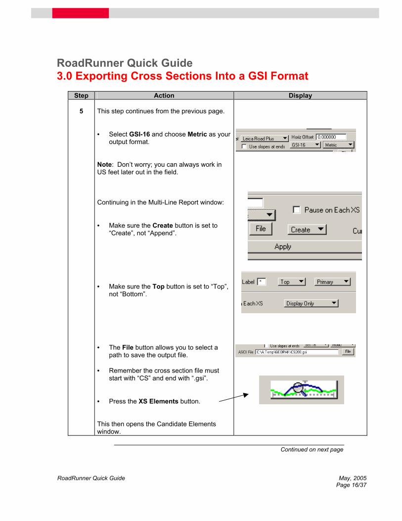
5 This step continues from the previous page. • Select GSI-16 and choose Metric as your
output format. Note: Don’t worry; you can always work in US feet later out in the field. Continuing in the Multi-Line Report window: • Make sure the Create button is set to
“Create”, not “Append”. • Make sure the Top button is set to “Top”,
not “Bottom”. • The File button allows you to select a
path to save the output file. • Remember the cross section file must
start with “CS” and end with “.gsi”. • Press the XS Elements button. This then opens the Candidate Elements window.
Continued on next page

RoadRunner Quick Guide May, 2005 Page 17/37
RoadRunner Quick Guide 3.0 Exporting Cross Sections Into a GSI Format
Step Action Display
6 In the Candidate Elements window: • Click on each element’s check box. • Press the Match button. • Move the Candidate Elements window
and the other menus out of the way in order so that you can see the cross section displayed on the screen.
• Left click on the cross section. • Notice the cross section has turned to a
purple colour. • If you have selected the correct line, left
click on it again to confirm the selection. This populates the fields in the Candidate Elements window. Don’t worry if your values do not match this example’s display. Note: If you have selected an incorrect line, you can deselect it by right clicking on it. • Close the Candidate Elements dialog
box. This step is continued on the following page.
Continued on next page
RoadRunner Quick Guide May, 2005 Page 18/37
RoadRunner Quick Guide 3.0 Exporting Cross Sections Into a GSI Format
Step Action Display
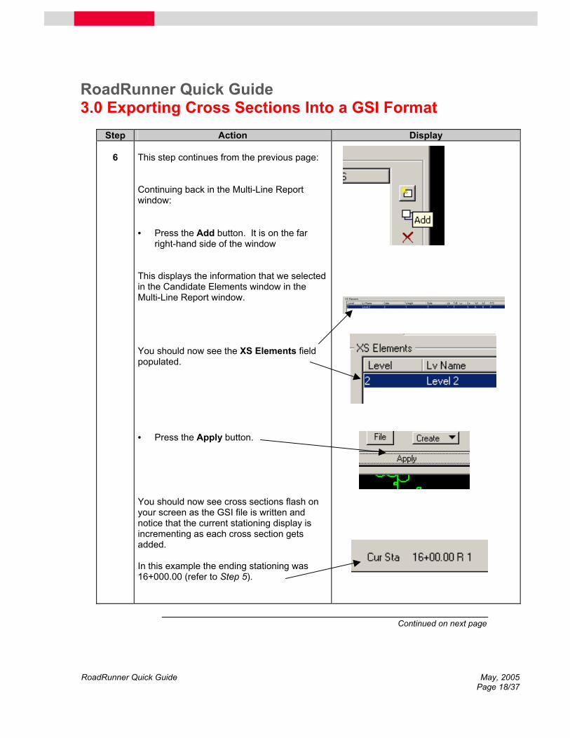
6 This step continues from the previous page: Continuing back in the Multi-Line Report window: • Press the Add button. It is on the far
right-hand side of the window This displays the information that we selected in the Candidate Elements window in the Multi-Line Report window. You should now see the XS Elements field populated. • Press the Apply button. You should now see cross sections flash on your screen as the GSI file is written and notice that the current stationing display is incrementing as each cross section gets added. In this example the ending stationing was 16+000.00 (refer to Step 5).
Continued on next page

RoadRunner Quick Guide May, 2005 Page 19/37
RoadRunner Quick Guide 3.0 Exporting Cross Sections Into a GSI Format
Step Action Display
7 Using Windows explorer, • Navigate to the folder where the cross
section files were written. You should now see three new GSI files.
Conclusion Congratulations you have just exported cross section information into a GSI format.
In the following section we will use the Design to Field tool within LGO to convert these GSI files into a RoadRunner Job format and connect the consecutive cross sections that have different numbers of vertices.

RoadRunner Quick Guide May, 2005 Page 20/37
RoadRunner Quick Guide 4.0 Using Design To Field To Convert GSI Files Into A Roadrunner Format
Step Action Display
1 From the main menu of LGO: • Click on the Tools pull-down menu at the
top of the screen. • Select Design to Field…. This opens the Design to Field Window.
2
From within the Design to Field window: • Press the New job button. This opens the Create Job window.
Continued on next page

RoadRunner Quick Guide May, 2005 Page 21/37
RoadRunner Quick Guide 4.0 Using Design To Field To Convert GSI Files Into A Roadrunner Format
Step Action Display
3 In the Create Job window: • Select a folder to store this job in using
the Create in field. • Enter a Job name in the Job Name field. Note: In this example we are calling the job “Center Line Stakeout”. • Select Road Importer from the Importer
Type field. • Press the OK button when finished. You have just created a road job. Now you must add the GSI data to this job. This closes the Create Job window and brings us back to the Design to Field window.
4
In the Design to Field window: • Select the GSI Importer in the Importer
field. • Press the Import… button. This starts the GSI-Import wizard.
Continued on next page

RoadRunner Quick Guide May, 2005 Page 22/37
RoadRunner Quick Guide 4.0 Using Design To Field To Convert GSI Files Into A Roadrunner Format
Step Action Display
5 In the GSI-Import wizard: • Press the Next button. This takes you to the Select GSI Files page of the wizard.
6
In the Select GSI Files page of the wizard: Here you select the GSI files that you wish to convert. For a full road design, four GSI files are required:
1. a horizontal alignment file (aln*.gsi) 2. a vertical profile file (prf*.gsi) 3. a cross section file (crs*.gsi) and a 4. a station assignment file (sta*.gsi).
• Place a check in each file inclusion
check box. Note: In this example we are including all road design files except station equations.
• Press the button next to each file field to navigate to where these files are stored and select them.
• Press the Next button when finished. This takes you to the Data Details page of the wizard.
Continued on next page
RoadRunner Quick Guide May, 2005 Page 23/37
RoadRunner Quick Guide 4.0 Using Design To Field To Convert GSI Files Into A Roadrunner Format
Step Action Display
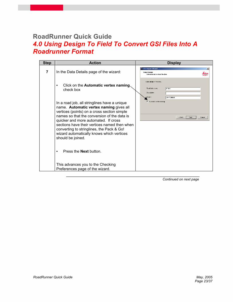
7 In the Data Details page of the wizard: • Click on the Automatic vertex naming
check box In a road job, all stringlines have a unique name. Automatic vertex naming gives all vertices (points) on a cross section simple names so that the conversion of the data is quicker and more automated. If cross sections have their vertices named then when converting to stringlines, the Pack & Go! wizard automatically knows which vertices should be joined. • Press the Next button. This advances you to the Checking Preferences page of the wizard.
Continued on next page

RoadRunner Quick Guide May, 2005 Page 24/37
RoadRunner Quick Guide 4.0 Using Design To Field To Convert GSI Files Into A Roadrunner Format
Step Action Display
8 In the Checking Preferences page of the wizard: • Examine the stationing and deflection
tolerances. These tolerances can be used as an additional tool to quality control your design. Sometimes the design distance of the stationing and the distance that Design to Field converter computes may differ (mostly due to different methodologies of rounding numbers or spiral computations). Although using these tolerances are optional, if there is a huge error in between the design chainages and what Design to Field determines, the road files cannot be created. • Press the Next button. This advances you to the Importing GSI Data page of the wizard.
Continued on next page
RoadRunner Quick Guide May, 2005 Page 25/37
RoadRunner Quick Guide 4.0 Using Design To Field To Convert GSI Files Into A Roadrunner Format
Step Action Display
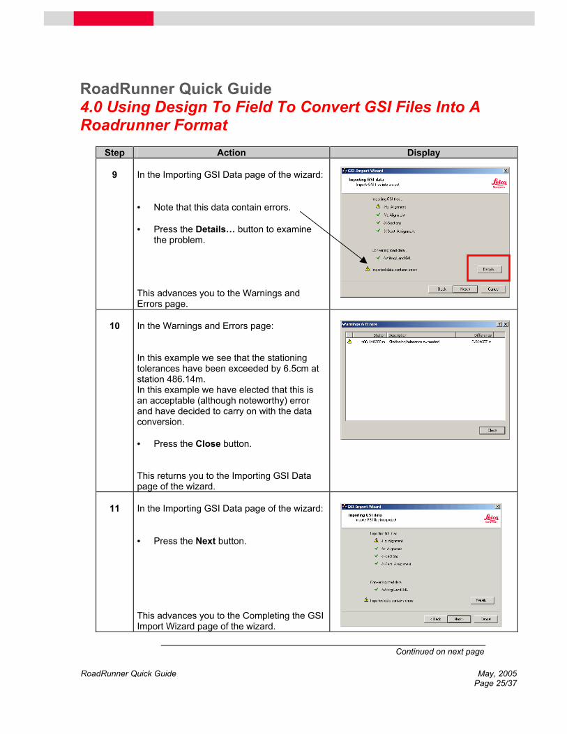
9 In the Importing GSI Data page of the wizard: • Note that this data contain errors. • Press the Details… button to examine
the problem. This advances you to the Warnings and Errors page.
10
In the Warnings and Errors page: In this example we see that the stationing tolerances have been exceeded by 6.5cm at station 486.14m. In this example we have elected that this is an acceptable (although noteworthy) error and have decided to carry on with the data conversion. • Press the Close button. This returns you to the Importing GSI Data page of the wizard.
11
In the Importing GSI Data page of the wizard: • Press the Next button. This advances you to the Completing the GSI Import Wizard page of the wizard.
Continued on next page

RoadRunner Quick Guide May, 2005 Page 26/37
RoadRunner Quick Guide 4.0 Using Design To Field To Convert GSI Files Into A Roadrunner Format
Step Action Display
12 In the Completing the GSI Import Wizard page of the wizard: • Notice an alert box appears alerting us
that the alignment chainage will be updated.
Note: Your data may not contain errors thus you will not see this alert box. • Press the OK button in the alert box. The Completing the GSI Import Wizard page of the wizard appears. • Examine the summary of imported data. • Press the Finish button when finished. This closes the wizard and returns you to the Design to Field window.
Continued on next page

RoadRunner Quick Guide May, 2005 Page 27/37
RoadRunner Quick Guide 4.0 Using Design To Field To Convert GSI Files Into A Roadrunner Format
Step Action Display
13 In the Design to Field window: We are now ready to convert the data. • Press the Pack & GO!… button. This advances you to the Pack & GO! wizard.
14
In the Pack & GO! wizard: • Press the Next button. This advances you to the Settings page of the Pack & GO wizard.
Continued on next page

RoadRunner Quick Guide May, 2005 Page 28/37
RoadRunner Quick Guide 4.0 Using Design To Field To Convert GSI Files Into A Roadrunner Format
Step Action Display
15 In the Settings page of the Pack & GO wizard: • Ensure that you have all the check boxes
checked as the display on the right. Interpolation between cross (X) sections allows you to choose how the stringlines between each of the cross sections should look like. They can run parallel to the center line or they can be interpolated out (or in) to the next cross section. Interpolation between cross sections is by far the most common method and therefore it is selected by default. Show only conflicts allows you to skip past cross sections that are identical. Only cross sections that are different (i.e. have a different number of vertices or the vertex has a different offset) are shown. Use Auto Solve for all vertex conflicts is a useful tool to make conversion more automated. Auto Solve connects any new vertices on the ahead cross section that have a greater offset than the back cross section’s widest vertices. Without this selected a conflict would only be shown and you would have to manually connect vertices. Note: this only works with named vertices. • Press the Next button. This advances you to the Name Vertices page of the Pack & GO wizard.
Continued on next page

RoadRunner Quick Guide May, 2005 Page 29/37
RoadRunner Quick Guide 4.0 Using Design To Field To Convert GSI Files Into A Roadrunner Format
Step Action Display
16 In the Name Vertices page of the Pack & GO wizard: In this example we see that the vertices have names that are not that intuitive to us so we will rename them. This will also give names to the stringlines. Note: You may not need to do this and you can skip this step but remember the vertices must have names. • Click on the first vertex (L3:1 in this
example) and rename it (in this example we are renaming it to “Lcatch” ).
• Press the button to advance to the next vertex.
• Continue naming the vertices. • Press the Next button when you have
finished naming the vertices. The Pack & GO wizard begins to build the stringlines.
Continued on next page

RoadRunner Quick Guide May, 2005 Page 30/37
RoadRunner Quick Guide 4.0 Using Design To Field To Convert GSI Files Into A Roadrunner Format
Step Action Display
17 In this example we have a cross section issue. The Vertex Management screen is displayed so we know there is a conflict and we must resolve this to continue. We can see question marks (?) at the vertices in question. In this example the RCatch and LCatch vertices in the ahead (or “forward”) cross section are not connected to those of the back cross section. We must connect these. • Click on the RCatch vertex in the top
cross section view. • Click on the vertex with the in lower
cross section view. • Press the Connect button. • Notice that the vertex in the lower view
(ahead cross section) is automatically given the same name as the vertex in the upper view (back cross section).
• Continue connecting conflicts until all the
question marks are gone. • Press the OK button. The wizard will continue to form stringlines until another conflict arises. This step continues on the following page.
Continued on next page

RoadRunner Quick Guide May, 2005 Page 31/37
RoadRunner Quick Guide 4.0 Using Design To Field To Convert GSI Files Into A Roadrunner Format
Step Action Display
17 This step continues from the previous page: • Continue resolving conflicts until all the
question marks are gone. Once the conflicts have been resolved, the Vertex Management wizard closes and the road job is created. This advances you to the Creating on-board data page of the Pack & GO wizard.
18
In the Creating on-board data page of the Pack & GO wizard: We are presented with a “Converting Completed” message. • Press the Next button. This advances you to the Completing the Pack & GO wizard page.
Continued on next page

RoadRunner Quick Guide May, 2005 Page 32/37
RoadRunner Quick Guide 4.0 Using Design To Field To Convert GSI Files Into A Roadrunner Format
Step Action Display
19 In the Completing the Pack & GO wizard page: We are presented with a summary of the completed tasks. • Press the Finish button. This closes the Pack & GO wizard and returns us to the Design to Field window in LGO.
20
In the Design to Field window in LGO: • Press the Close button and shut down
LGO.
Continued on next page

RoadRunner Quick Guide May, 2005 Page 33/37
RoadRunner Quick Guide 4.0 Using Design To Field To Convert GSI Files Into A Roadrunner Format
Step Action Display
21 From within Windows: • Use Windows explorer to browse to
where you told the exporter to store the RoadRunner job.
• Remember from Step 3 we called this job
“Center Line Stakeout”. • Copy these files onto the System 1200
CF (compact flash) card into the DBX folder.
Conclusion Congratulations you have just converted GSI files into a RoadRunner job. You also
learned how to deal with cross section conflicts. In the following section we will export horizontal and vertical profiles using GEOPAK’s Leica (DBX) exporter.

RoadRunner Quick Guide May, 2005 Page 34/37
RoadRunner Quick Guide 5.0 Exporting Alignments and Profiles Using the Leica (DBX) Exporter in GEOPAK
Introduction In the previous 4 sections we explored exporting horizontal alignments, vertical
profiles, and cross sections out of GEOPAK in a GSI format. We then used the Design to Field Importer in LGO to convert these GSI files into a RoadRunner job. In this section we will explain how to use the Leica (DBX) exporter in GEOPAK to export horizontal alignments and vertical profiles straight into a RoadRunner job. Remember currently we cannot use this exporter to export cross sections because there is no way of handling cross section conflicts.
Step Action Display
1
From the main menu of MicroStation: • Open the project that contains the
horizontal alignments and vertical profiles that you wish to export into a RoadRunner job.
• Click on the Geometry pull-down menu
and select Export. • Click on Leica (DBX) from the next menu
that opens up. This opens the Export Leica (RoadRunner DBX) window.
Continued on next page

RoadRunner Quick Guide May, 2005 Page 35/37
RoadRunner Quick Guide 5.0 Exporting Alignments and Profiles Using the Leica (DBX) Exporter in GEOPAK
Step Action Display
2 In the Export Leica (RoadRunner DBX) window: • Enter a job name in the Project (Job)
Name field. In this example we are calling the job “Center Line”. • Press the button to select a folder to
store the job. Once completed the folder path will be listed in the Output Dir field.
• Press the Element Type button and
select Chains. • Notice that more fields appear. • Decide if you would like to export one or
all the chains. • Place a check in the Export Profile(s)
check box to export a profile with the alignment.
• Notice that the profile associated with this
project is then listed in the Profile list box.
• Press the Export button. You have just exported a horizontal alignment and a vertical profile straight into a RoadRunner job!
Continued on next page

RoadRunner Quick Guide May, 2005 Page 36/37
RoadRunner Quick Guide 5.0 Exporting Alignments and Profiles Using the Leica (DBX) Exporter in GEOPAK
Step Action Display
3 From within Windows: • Use Windows Explorer to browse to
where you told the exporter to store the RoadRunner job.
• Notice that all the file names begin with
the job name we entered in Step 2. • Copy these files onto the System 1200
CF (compact flash) card into the DBX folder.
Congratulations You have just exported a horizontal alignment and a vertical profile out of
GEOPAK and straight into a RoadRunner job. Remember that at this time (May 2005) cross section data with cross sections that contain different numbers of vertices must be dealt with using GSI files and the Design to Field Importer in LGO (see sections 1-4).

RoadRunner Quick Guide May, 2005 Page 37/37
6.0 Acknowledgements
Special Thanks Without the gracious generosity of Bentley Systems in letting us use their software,
this quick would never have been written. Special thanks goes to Rod Levengood for supplying me with the license files allowing me to use Bentley’s software during the writing of this quick guide. An extra special mention of appreciation goes to Fernando Abad of Bentley Systems for providing me with instructions on how to export alignments, profiles, and cross sections out of MicroStation using GEOPAK. He also provided me with MicroStation alignment files and cross section files that I used as examples to write this paper. Without his patience, knowledge, and wonderful instructions, this quick guide would never have been written.