Embed Size (px)
Citation preview

DRAFT KENYA STANDARD DKS 372: 2010
Road vehicles — Passenger vehicle body construction — Specification
PUBLIC REVIEW DRAFT, SEPTEMBER 2010
ICS 43.100
KEBS 2010 Third Edition 2010©

DKS 372: 2010
TECHNICAL COMMITTEE REPRESENTATION
REVISION OF KENYA STANDARDS
©
© Kenya Bureau of Standards, 2010
Copyright: Users are reminded that by virtue of section 6 of the Copyright Act, Cap. 130 of the Laws of Kenya, copyright subsists in all Kenya Standards and except as provided under section 7 of this Act, no Kenya Standard produced by Kenya Bureau of Standards may be reproduced, stored in a retrieval system in any for or transmitted by any means without prior permission in writing from the Managing Director.
KEBS 2010 — All rights reservedii
The following organizations were represented on the Technical Committee:
Ministry of Roads and Public Works — Mechanical Engineering Department Automobile Association of KenyaOffice of the President — Vehicle Inspection UnitKenya Vehicle Manufacturers Ltd.Kenya Industrial Research and Development Institute (KIRDI)General Motors (K) Ltd.Association of Vehicle Assemblers Ltd (AVA)Kenya Auto Bazaar Association (KABA)Kenya Used Motor Parts Importers Association (KUMPIA)Kenya Automotive Repairers Association (KARA)Mutsimoto Motor Company LtdKenya Bus Services LtdKenya Bureau of Standards — secretariat
In order to keep abreast of progress in industry, Keny Standards shall be regularly reviewed. Suggestions for improvements to published standards, addressed to the Managing Director, Kenya Bureau of Standards, are welcome.
ISBN 9966-07-324-8

DRAFT KENYA STANDARD DKS 372: 2010
Road vehicles — passenger vehicle body construction — Specification
K E N Y A B U R E A U O F S T A N D A R D S ( K E B S )
Head Office:
Coast Region Lake Region North Rift Region
© KEBS 2010 — All rights reserved iii
ICS 43.100
P.O. Box 54974, Nairobi-00200, Tel.: (+254 020) 605490, 602350, Fax: (+254 020) 604031E-Mail: [email protected], Web:http://www.kebs.org
P.O. Box 99376, Mombasa-80100 P.O. Box 2949, Kisumu-40100 P.O. Box 2138, Nakuru-20100
Tel.: (+254 041) 229563, 230939/40 Tel.: (+254 057) 23549, 22396 Tel.: (+254 051) 210553, 210555Fax: (+254 041) 229448 Fax: (+254 057) 21814

DKS 372: 2010
Foreword
©
Following the approval of this standard the body building industry shall be given upto 1st July 2011 to implement the use of Q345 material or it’s equivalent.
KEBS 2010 — All rights reservediv
This Kenya Standard was prepared by the Road Vehicle Technical Committee under the guidance of the Standards Projects Committee and it is in accordance with the procedures of the Bureau.
This standard was formulated to be of guidance to the rapid growing passenger vehicle transport system, for safety and comfort of passengers and general road safety requirements. This standard will help harmonize the various sizes of passenger vehicles.
During the development of this standard, reference was made to the following documents:
KS 649: 1989 Specification for automobile windscreens.
KS 376: 1999 Specification for flexible polyurethane (polyester) foams.
KS 1515:2000 Code of practice for inspection of road vehicles.
KS ISO 898 Mechanical properties of fasteners.
KS ISO 7165 Fire fighting — Portable fire extinguishers.
E/ECE/324: 2002 United Nations Agreement concerning the adoption of un technical prescriptions for wheeled vehicles, equipment and parts, which can be fitted and/or be used on wheeled vehicles and the conditions or reciprocal recognition of approvals granted on the basis of these prescriptions.
KS 664:1999 Specification for seat belt assemblies for motor vehicles.
KS 822:1999 Specification for anchorages for seat belts for automobiles.
KS 1017 Specification for approval testing of welders working approved welding procedures.
KS 376: 1999 Specification for flexible polyurethane foams.
TZS – 598:1999
Acknowledgement is made for the assistance derived fro these sources.

DRAFT KENYA STANDARD DKS 372: 2010
Road vehicles — Passenger vehicle body construction — Specification
1 Scope
2 Definition and field of application
2.1vehicle
2.2articulated bus or coach
2.3low floor vehicle
2.4vehicle type
2.5approval of a vehicle
2.6service door
2.7double door
2.8emergency door
© KEBS 2010 — All rights reserved 1
This Kenya Standard specifies requirements for passeng vehicles body construction.
This standard applies to vehicles with bodies designed and constructed for carriage of persons. This standard does not include provisions for persons of re uced mobility.
This standard does not apply to saloon cars, station w gons and other public transport vehicles other than those specified in 2.1.
For the purpose of this Kenya Standard the following d ions shall apply:
a bus designed and equipped for the transport of passengers. (See Clause 3 for vehicle classification)
a vehicle, which consists of two or more rigid sections, which articulate relative to one another. The passenger compartments of each section intercommunicate so that passengers can move freely between them. The rigid sections are permanently connected so hat they can only be separated by an operation involving facilities which are normally only found in a workshop
a vehicle in which at least 35 % of the area available for standing passengers (or of its forward ection in the case of articulated vehicles) forms a single area without steps, reached through at least one service door by a single step from the ground
a vehicle, which do not differ essentially with regard to the constructional features specified in this standard
the approval of a vehicle type with regard to the constructional features specified in this standard
a door used by passengers in normal circumstances providing access to and from vehi le
a door affording two, or the equivalent of two access ages
a door additional to the service door(s) intended for use as an exit by passengers in an emergency only

© KEBS 2010 — All rights reserved2
a window, not necessarily glazed, intended for use as exit by passengers in an emergency only
an emergency window which, when divided into two by an imaginary vertical line (or plane), exhibits two parts each of which complies as to dimensions and acce with the requirements applicable to a normal emergency window
a roof provision intended for use as an exit by passen s in an emergency only
an emergency door, emergency window or escape hatch
means a service door or emergency exit
that part of the bodywork whose upper surface supports standing passengers, the feet of seated passengers and the driver, and the seat mountings
the passage providing access by passengers from any se row of seats to any other seat or row of seats or to any access passage from or to any service door; it does not include:
a) the space extending 30 cm in front of any seat;
b) the space above the surface of any step or staircase; or
c) any space, which affords access solely to one seat or one row or seats.
the space extending inwards into the vehicle from the ervice door up to the outermost edge of the upper step (edge of the gangway). Where there is no step at the door, the space to be considered as access passage shall be up to a distance of 30 cm from the st ng position of the inner face of a dual panel.
the space intended for the driver’s exclusive use and containing the driver’s seat, the steering wheel, controls, instruments and other devices necessary for the vehicle.
the mass of the vehicle in running order unoccupied and un-laden
the maximum mass declared by the manufacturer of the vehicle. (This mass may be greater than the “permissible maximum mass” to be prescribed by national administrations)
2.9emergency window
2.10double emergency window
2.11escape hatch
2.12emergency exit
2.13exit
2.14floor or deck
2.15gangway
2.16access passage
2.17driver’s compartment
2.18tare mass (MK) (kg)
2.19technically permissible maximum mass

DKS 372: 20102.20technically permissible maximum axle mass
2.21passenger
2.22passenger with reduced mobility
2.23passenger compartment
2.24automatically operated service door
2.25starting prevention device
2.26driver operated service door
2.27RHS
2.28M.S
2.29cant rail
2.30MIG
© KEBS 2010 — All rights reserved 3
that part of the technically permissible maximum mass of the vehicle, d red by the manufacturer, which results in the vertical force at the road surface in the contact area on the wheel/wheels of an axle. This mass may be greater than the maximum permissible axle mass authorized by national administrations. The sum of all technically permissible maximum axle masses of he vehicle may be greater than the technically permissible maximum mass of that vehicle
a person other than the driver or a member of the crew
a passenger who has a special difficulty when using pu lic transport, especially elderly and disabled person. Reduced mobility does not necessarily imply any form of medical impairment
the space intended for passengers use excluding any space occupied by fixed appliances such as bars, kitchenettes or toilets
a power-operated service door which can be opened (other than by means of emergency controls) only after a control is operated by a passenger, and after activation of the controls by the driver, and which closes again automatically
a device, which prevents the vehicle from being driven away from rest when a door is not fully closed;
a service door, which normally is opened and closed by the driver
NOTE 1: Unless otherwise stated, all measurements shall be mad when the vehicle is at its unladen kerb mass (MK) (kg) and it is standing on a smooth and horizontal ground surface. If a kneeling system is fitted to the vehicle, i t shall not be in operation.
NOTE 2: Wherever there is a requirement in this standard for a surface in the vehicle to be horizontal or at a specific angle when the vehicle is at its unladen kerb mass (MK) (kg), in the case of a vehicle with mechanical suspension, the surface may exceed this slope or possess a slope when the vehicle is in the loading con on declared by the manufacturer. If a kneeling system is fitted to the vehicle, it shall not be in operation.
rectangular hollow section
mild Steel
longitudinal stiffeners that provide support over the windows of the vehicle
metal inert gas

© KEBS 2010 — All rights reserved4
tungsten inert gas
For the purpose of this standard, passenger vehicles shall be classified into the following five classes:
Class I Micro-buses with a seating capacity of up to 14 passengers;
Class II Mini-buses with a seating capacity of 15 — 25 passengers;
Class III Medium-buses with a seating capacity of 26 — 40 passengers;
Class IV Buses with a seating capacity of over 40 passengers;
Class V Urban buses with a capacity of over 40 seated passenge s;
Class VI Double decker buses with a capacity of over 40-seated passengers.
NOTE 1 Each of the above classifications shall be separated into:
A Urban type;
B Interurban type.
NOTE: 2 The carrying capacity shall be as permitted by the tra ic act.
All body builders shall be accredited by Kenya National Accreditation Services (KENAS).
Approvals for vehicle designs shall be authorized by relevant registered engineer(s) to specific vehicle type as registered with KENAS and shall ensure that vehicle bodies are constructed t manufacturers specifications and safety.
Application for approval of a vehicle type, with regar to its constructional features, shall be submitted by the vehicle body builder to KENAS
The application shall include a detailed description of the vehicle type, its structure, dimensions, configuration, and constituent materials. The followi g shall also be submitted:
a) drawings of vehicle and its interior arrangements;
b) the unladen mass of the vehicle in kg;
c) the technical maximum mass of each axle;
d) the intended total number of passengers (N) as calculated in Annex A;
e) the class for which approval is requested.f) KENAS Type approval Number i.e
2.31 TIG
3 Vehicle classification
3.1
4 Requirements
4.1 Conformity of production
4.1.1 Accreditation of body builders
4.1.2 Authorization of vehicle designs
4.1.3 Application for approval
4.1.3.1

DKS 372: 2010
4.2
4.3 Drilling and welding of chassis
4.3.1 Vehicle chassis welding
4.3.2 Welding of body structure and cladding
4.3.3 Arc welding
4.3.4 MIG and TIG equipment
4.3.5 Vehicle chassis drilling
4.4 Body sections
© KEBS 2010 — All rights reserved 5
Vehicles shall be built by approved body builders and accordance with requirements of this standard and shall conform to 4.1.
The body structures shall not be welded to the chassis. Brackets shall be b ed to the chassis, on which the body structure can be welded, and in line with vehicle manufacture’s specifications.
Welders shall be approved in accordance with KS 1017, Specifications for testing of welders working to approved welding procedures.
Arc welding shall be limited to the welding of angle iron or channel iron sections in excess of 6 mm, to chassis mounting brackets.
The MIG and TIG equipment shall be employed for welding all other material including RHS, lip channel and cladding sheets.
Chassis drilling shall follow manufacturer’s recommendations and shall achieve a "push fit" with the fixings employed.
The materials used shall be Q345 or equivalent and dimensions of body sections shall be as specified in Table 1, or may be different if a finite element analysis is submitted to KENAS at approval stage, which shows that an alternate is safe.

© KEBS 2010 — All rights reserved6
Body cross members RHS 100 mm x 50 mm x 3 mm Channel 100 mm x 50 mm x 6 mm
Seat anchorageContinuous oval or circular tubular 40 mm x 40 mm x 4.5 mm
Continuous oval or circular tubular 40 mm x 40 mm x 4.5 mm
Floor covering M.S. chequer plate 3.0 mm orM.S. (flat) plate 2.5 mm with anti-skid covering or marine ply 10.0 mm with floor covering
M.S. chequer plate 3.0 mm or M.S. (flat) plate 2.5 mm with anti-skid covering
Side verticles RHS 40 mm x 40 mm x 2.0 mm RHS 60 mm x 40 mm x 2.5 mm or Lip channel 80 mm x 40 mm x 2.5 mm
Side horizontals RHS 40 mm x 40 mm x 2.0 mm, and shall be diagonally braced.
RHS 60 x 40 mm x 2.5 mm orLip channel 80 mm x 40 mm x 2.5 mm, and shall be diagonally braced.
Window spacings
min. 940 mm 940 mmmax. 1 150 mm 1 150 mm
Window height
Sliding 600 mm 600 mmFixed 430 mm 430 mm
Sliding window position Top position for all school buses and either position for other applications (see Figure 2)
Top position for all school buses and either position for other applications (see Figure 2)
Cant rail Angle iron 40 mm x 40 mm x 3 mm, with strip of 3mm flat bar to form continuous triangular section
Angle iron 60 mm x 40 mm x 3 mm or 80 mm x 40 mm x 3 mm, with strip of 3mm flat bar to form continuous triangular section
Roof sticks To be formed into even radius and raised to 200 mm over cant rail, and following line of side verticals 60 mm x 40 mm x 1.5 mm and fit intermediate roof sticks. Weld angle iron to roof sticks for the attachment of roof rack fixings
To be formed into even radius and raised to 200 mm over cant rail, and following line of vertical side rails. 80 mm x 40 mm x 2.0 mm or fit intermediate roof sticks. Weld angle iron to roof sticks for the attachment of roof rack fixings
Roof longitudinals Material as for roof sticks. Weld in four equally spaced to support the centre cladding (48")
Material as for roof sticks. Weld in four equally spaced to support the centre cladding (48")
Outer cladding M.S., galvanized 0.5 mm(for glued skin) and 0.8mm (for welded skin), or aluminium 1 mm
M.S., galvanized 0.5 mm(for glued skin) and 0.8mm (for welded skin), or aluminium 1 mm
Inner cladding M.S., galvanized 0.5 mm(for glued skin) and 0.8mm (for welded skin),, or aluminium 0.8 mm
NOTE: Shall be full coverage inside with no sharp edges.
M.S., galvanized 0.5 mm(for glued skin) and 0.
um 0.8 mm
NOTE Shall be full coverage inside with no sharp edges.
Front and rear sections
Must have strong supporting structure as for side frames (braced), for either metal sheeting (18 guage) or fibreglass
Must have strong supporting structure as for side frames (braced), for either metal sheeting (18 guage) or fibreglass
Table 1 — Material and dimensions of body sections
Body sections Class II, III Class IV, V, VI
8mm (for welded skin),,or alumini

DKS 372: 2010
4.5 Gangways
4.5.1 Floor to roof height
4.5.2 Gangway measurements
Table 2 — Gangway measurements in mm
Dimensions Class II Class III Class IV, V and VI
© KEBS 2010 — All rights reserved 7
The minimum inside floor to roof height for vehicle classes II and III shall be minimum 1 700 mm, while for vehicles of classes IV, V and VI shall be minimum 1 800 mm. The maximum (overall) height shall be 1 900 mm.
The gangway for public service vehicle shall be so designed and constructed as to permit the free passage of gauging devices whose dimensions are as specified in Table 2 and as illustrated in Figure 1.
Diameter of lower cylinder 300 350 450Height of lower cylinder 900 900 900Diameter of upper cylinder 450 550 550Height of upper cylinder 500 500 500Overall height 1 700 1 800 1 900

© KEBS 2010 — All rights reserved8
The recommended windows design for vehicles of class I IV, V and VI shall be made of three parts, as shown in the Figure 2. Window dimensions shall be as s ied in Table 1.
Figure 1 — Gangway gauging device
4.6 Windows
4.6.1 Window design and construction

DKS 372: 2010
Figure 2 — Typical window design
4.6.2
4.6.3
4.6.4
4.6.5 Compliance of window glass and windscreens
4.6.6 Front windscreen
4.6.6.1
4.6.6.2
4.7 Hand-rails and hand-holds
4.8 Emergency exits/entrances
© KEBS 2010 — All rights reserved 9
The windows shall be fixed to the vertical pillars firmly.
Window fittings shall be of good quality and weather proof.
The windows shall be so designed and constructed as to allow proper view and ventilation.
Window glass and windscreens shall comply with KS 649, Specification for automotive windscreens.
The windscreen and side-windows of the driver’s compartment shall be construct as to give the driver adequate view ahead and to either side at an angle of at least 90o from the centre line of the vehicle.
The corner posts and pillars supporting the windshield shall be 100 mm max. and 50 mm max. respectively. They shall be so designed and constructed such that they do not impair driver’s visibility as in 4.6.6.1.
Every public service passenger vehicle shall be provided with hand-rails and hand-holds which are of adequate strength and so designed and installed as to resent no risk of injury to passengers. Every hand-rail shall provide a length of at least 10 cm to accommodate a hand. The hand-rails shall have a diameter greater than 20 mm and less than 45 mm except for hand-rails on doors and seats.
All vehicles shall be provided with an unhindered emer ncy exit with a clearly marked direction of opening at the back of the vehicle of height not less than 1 2 0 mm and width not less than 457 mm.
© KEBS 2010 — All rights reserved10
Emergency doors shall be capable of being easily opened from inside and from outside when the vehicle is stationery.
Emergency doors shall not be of the power-operated or the sliding type.
The driver shall make sure that all emergency doors ar securely closed.
Entrance and exits of the vehicle shall be through ser ice door(s) or double door(s) situated on the left side of the vehicle, whose minimum height for class II, III and IV shall be 1 650 mm, and for class V, 1 800 mm while the minimum width for single door shall be 450 mm and for double shall be 1 200 mm.
The minimum number of service doors required is as fol s:
a) class V and VI vehicle shall have minimum two double doors;
b) class III and IV shall have minimum one service doors.
Entrance and service doors shall not be deemed to be a gency door.
Emergency windows shall be rectangular, measuring 700 mm x 500 mm minimum.
Every hinged emergency window shall open outwards.
Every emergency window shall be capable of being easil and instantaneously operated from inside and from outside the vehicle by means of a device recognized as satisfactory by the authority, or shall be made of readily breakable safety glass. This shall pre the possibility of using panes of laminated glass or plastic material.
Every vehicle shall be fitted with a suitable ventilat r constructed such that it shall under normal use, not leak rainwater into the vehicle.
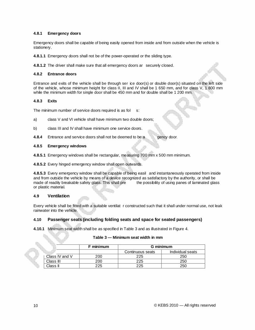
Minimum seat width shall be as specified in Table 3 and as illustrated in Figure 4.
Continuous seats Individual seatsClass IV and V 200 225 250Class III 200 225 250Class II 225 225 250
4.8.1 Emergency doors
4.8.1.1
4.8.1.2
4.8.2 Entrance doors
4.8.3 Exits
4.8.4
4.8.5 Emergency windows
4.8.5.1
4.8.5.2
4.8.5.3
4.9 Ventilation
4.10 Passenger seats (including folding seats and space for seated passengers)
4.10.1
Table 3 — Minimum seat width in mm
F minimum G minimum

DKS 372: 2010
Figure 3 — Doors
© KEBS 2010 — All rights reserved 11

© KEBS 2010 — All rights reserved12
The minimum seat spacing for legroom shall be 660 mm f r class V and VI, while for other classes the minimum seat spacing shall be 680 mm, when the seats are arranged one behind the other.
The seats shall be firmly bolted on the floor steel fr k and not on floor sheets with bolts complying with KS ISO 898. The general seat construction shall be as strated in Figure 5. The tubes used in the construction of seats shall be round or oval shaped and of minimum 25 mm diameter and minimum 2 mm thickness and of grade A.
WhereH = seat spacingI = Cushion height
Figure 4 — Width of passenger seats
4.10.2 Seat spacing and cushion height
4.10.3 Seat anchorage
Figure 5 — Seat spacing and cushion height

DKS 372: 20104.10.4 Seat belts anchorage
4.10.4.1
Figure 6 — Seat belt anchorage for vehicles
4.10.4.2
4.11
4.12
4.13 Cushions
4.14
4.15 Interior lighting
4.16 Height above ground and steps for passengers
© KEBS 2010 — All rights reserved 13
The seat belts and their anchorage fitted in vehicles ll meet the requirements specified in KS 664, Specification for seat belt assemblies for motor vehicles and KS 822, Specification for anchorages for seat belts — Automobiles.
All vehicles shall be provided with 3-point seat belts for the driver’s seat, and all other osed seats as shown in Figure 6. The other seats may be provided with 2-point seat belts.
All other classes of vehicles shall be provided with seat belts for each seat.
The minimum clearance from the roof to the head for cl sses III, IV, V and VI of a standard height passenger 1.95 m shall be 0.3 m.
Each seat shall have a height difference of 25 mm between the front and rear legs to facilitate inclination.
If used, cushions for the seat and backrest shall be made of high-density foam conforming to KS-376, Specification for flexible polyurethane foams.
The combination of the plywood and foam must be reinforced with steel sections or flat bar of 25 mm x 3 mm.
All vehicles shall have interior lights operated by the driver and two bell switches, operated by the passengers to alert the driver to stop. The bell switches shall be on the inside roof one at about 610 mm from the rear emergency door and the other switch at a dist ce of about 300 mm from the driver’s partition.
The lowest step for entering into the vehicle shall not exceed a eight of 460 mm from the ground.

© KEBS 2010 — All rights reserved14
D shall be the height above the ground of vehicle unla . D, for class V shall be maximum 360 mm, while for other classes, D shall be 400 mm maximum. Mechanical suspensions shall solely be maximum 430 mm.
Space shall be provided for fitting one or more fire extinguishers, such that one is near the driver’s seat and the space provided for each measuring not less than 600 mm x 200 mm x 200 mm.
Class III, IV and V vehicle shall be provided with dry hemical powder type of fire extinguisher for general purpose use (ABC) ranging from 1.5 kg to 2.0 k . Fire extinguisher complying with KS ISO 7165, Fire fighting — Portable fire extinguishers — Performance and construction. While classes I, II shall use fire extinguisher type 0.6 kg minimum complying with KS ISO 7165.
Space shall be provided for fitting one or more first aid The space provided shall be not less than 7 dm3; the minimum dimension shall be not less than 80 mm.
Every vehicle shall be provided with a fully equipped st aid box.
Vehicles shall be constructed such that engine noise shall be limited to 90 decibels inside the vehicles.
Figure 7 — Height above ground and steps for passengers
4.17 Fire extinguisher
4.17.1
4.17.2
4.18 Emergency first aid equipment
4.18.1
4.18.2
4.19

DKS 372: 2010
4.20 Locks
4.21 Maneuvorability
4.21.1
4.21.2
© KEBS 2010 — All rights reserved 15
Every vehicle shall be fitted with quality passenger d or locks, boot locks and window locking devices shall hold the window firmly preventing it from sliding.
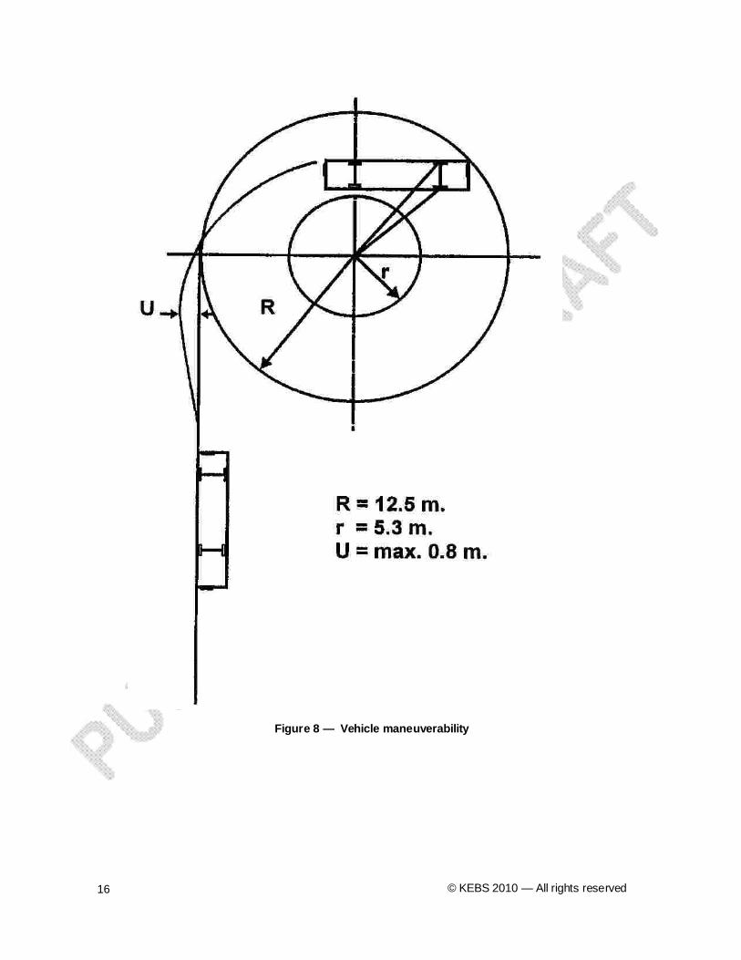
The vehicle shall be able to maneuver on either lock, inside a circle of 12.5 m radius, without any of its outermost points projecting outside the circumference of the circle.
When the outer points of the vehicle are moving on either lock on a circle of 12.5 the vehicle shall be able to move within the limits of a circular ck 7.2 m wide (see Figure 8).
© KEBS 2010 — All rights reserved16
Figure 8 — Vehicle maneuverability

DKS 372: 2010
4.22 Engine noise reduction
4.23 Protection against fire risks
4.23.1 Fuel tanks
4.23.1.1
4.23.1.2
4.23.1.3
4.23.2 Fuel-feed systems
4.23.2.1
4.23.2.2
4.23.2.3
4.23.2.4
4.23.3 Fuel filler holes
4.23.1
4.23.3.2
4.23.4 Fuel filler hole caps
4.24 Electrical equipment and wiring
4.24.1
© KEBS 2010 — All rights reserved 17
Non-flammable sound-proof material or materials, which are not liable to be impregnated with fuel or lubricant, shall be used in the engine compartment.
A partition of heat-resistant material shall be fitted between the engine compartment or other source of heat and rest of the vehicle.
Fuel system assembly shall be in accordance with KS 13 , Recommendation for fuel tank assembly for automotive.
Every fuel tank shall be securely fixed. No part of a fuel tank shall be less than 600 mm from the front of the vehicle or less than 300 mm from the rear vehicle so as to provide protection in the event of front or rear impact.
No part of the fuel tank shall project beyond the overall width of the bodywork.
Fuel tanks shall be made so as to be corrosion resistant.
No apparatus used for the fuel feed shall be placed in the driver’s compartment or the passenger compartment.
Fuel lines and all other parts of the fuel-feed system shall be accommodated in the positions on the vehicle where they have the fullest reasonable protect .
Twisting or bending movements and vibrations of the vehicle structure or the power unit shall not subject the fuel lines to abnormal stress.
Fuel leaking from any part of the system shall be able to flow away freely to the road surface, but never onto the exhaust system.
Fuel filler holes shall be accessible only from outside the vehicle.
Fuel filler holes shall be not less than 500 mm from any door aperture when the fuel tank is intended to contain petrol, and not less than 250 mm when it is intended to contain diesel fuel; they shall moreover not be in the passenger compartment, nor in the driver’s compartment.
Fuel filler hole caps shall be so designed and constru d that they cannot be opened accidentally.
All cables shall be well insulated and all cables and electrical equipment shall be able to withstand the temperature and humidity conditions to which they are exposed. Cables used in the engine compartment shall be able to withstand the environmental temperature, oil and vapour.

© KEBS 2010 — All rights reserved18
All cables shall be well protected and shall be held securely in position in such a way that they cannot be damaged by cutting, abrasion or chafing.
There shall be at least two internal lighting circuits such that failure of one will not affect the other.
Every electrical circuit feeding an item of equipment other than the starter, the ignition circuit (positive ignition), the glow-with, the engine-stopping device, the battery-charging circuit and the battery, shall include a fuse or a circuit breaker.
All batteries shall be secured and easily accessible.
The battery compartment shall be separated from the passenger compartment and driver’s compartment and ventilated to outside air.
The overall length of class — Classes IV, V and VI including any parts projecting from front to rear shall not exceed 12.5 metres.
The overall width of class — Classes IV, V and VI shall not exceed 2.65 m.
Every vehicle shall have an approval mark as prescribed in this standard after undergoing sufficient random inspection in the form of plate specified in annex C. Approval granted shall be withdrawn if this requirement is not complied with and production discon inued.
Every vehicle shall be inspected in accordance with re ts of KS 1515, code of practice for inspection of road vehicles. Dimension inspections shall ensure that vehicle external dimensions are in accordance with this standard and the design authorized by KENAS. A vehicle shall be inspected with all parts and accessories in place.
The following information shall be legibly and indelib marked on a plate permanently affixed on the side of the vehicle body:
a) manufacture/body builder’s name, address and trade mark;
b) year of manufacture;
c) capacity;
d) batch number;
4.24.2
4.24.3
4.24.4
4.25 Batteries
4.25.1
4.25.2
5 External dimensions
5.1 Overall length
5.2 Overall width
6 Inspection and criteria of conformity
6.1 During Production
Every vehicle shall be inspected by an engineer accredited by KENAS at end of the framing stage, for the integrity of the welding and materials used in the building of the frame. They will sign for conformity of this frame, using the form in annex B.
6.2. Final Inspection
6.2.1
6.2.2
The accredited engineer shall sign for conformity, using the form in annex B, which shall be a requirement for registering this PSV vehicle.
7 Marking

DKS 372: 2010
© KEBS 2010 — All rights reserved 19
e) reference to this standard.
© KEBS 2010 — All rights reserved20
(informative)
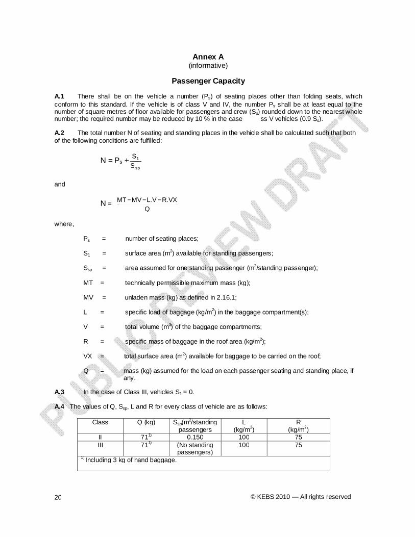
There shall be on the vehicle a number (Ps) of seating places other than folding seats, which conform to this standard. If the vehicle is of class V and IV, the number Ps shall be at least equal to the number of square metres of floor available for passengers and crew (So) rounded down to the nearest whole number; the required number may be reduced by 10 % in the case ss V vehicles (0.9 So).
The total number N of seating and standing places in the vehicle shall be calculated such that both of the following conditions are fulfilled:
N = Ps +sp
1
S
S
and
N = Q
R.VXL.VMVMT
where,
Ps = number of seating places;
S1 = surface area (m2) available for standing passengers;
Ssp = area assumed for one standing passenger (m2/standing passenger);
MT = technically permissible maximum mass (kg);
MV = unladen mass (kg) as defined in 2.16.1;
L = specific load of baggage (kg/m2) in the baggage compartment(s);
V = total volume (m3) of the baggage compartments;
R = specific mass of baggage in the roof area (kg/m2);
VX = total surface area (m2) available for baggage to be carried on the roof;
Q = mass (kg) assumed for the load on each passenger seating and standing place, if any.
In the case of Class III, vehicles S1 = 0.
The values of Q, Ssp, L and R for every class of vehicle are as follows:
Class Q (kg) Ssp(m2/standing
passengersL
(kg/m3)R
(kg/m2)II 711) 0.150 100 75III 711) (No standing
passengers)100 75
1) Including 3 kg of hand baggage.
Annex A
Passenger Capacity
A.1
A.2
A.3
A.4
−−−