Embed Size (px)
Citation preview

Road & Bridge Design Publications
Monthly Update – May 2017
1
Revisions for the month of May are listed and displayed below. E-mail road related questions on these changes to [email protected]. E-mail bridge related questions to [email protected]. Special Details R-49-G: Concrete Barrier: Revised barrier design to the “single slope” shape with a 42” height, 16” top, and 32” bottom. R-50-G: Light Standard Foundation: Revised design to include: the new single slope shape, decreased steel spacing (more steel) in the barrier and the foundation, and revised bar shapes while retaining the previous anchor bolt details and spread footing foundation. R-51-E: Sign Support Foundation: Revised design to include: the new single slope shape, decreased steel spacing (more steel) in the barrier and the foundation, “C” bars replacing “D” bars, while retaining the previous anchor bolt details and spread footing foundation. R-54-I: Concrete Barrier, Single Face: Revised design for the single slope shape. R-71-C: Guardrail Anchorage, Median: Revised anchorage for the single slope shape. R-76-E: Concrete Glare Screen: Revised glare screen dimensions to fit single slope shape. Since the new barrier uses concrete with a compressive strength of 5000 psi, a frequently used special provision is required for standard concrete barrier pay items. (A FUSP has been submitted and is pending approval.) The new barrier details are required in all projects beginning with the January 2018 letting. Until then, any projects not using the new barrier should reference the outdated standard plans unless project specific details and pay items are used. Please note that it may be necessary to retain a copy of the outdated standard plans until all projects using these plans have been completed.

Road & Bridge Design Publications
Monthly Update – May 2017
2
Road Design Manual 3.11.01: Freeway 3R/4R: A paragraph was modified to reflect a recent clarification in FHWA policy which indicates that design values for all controlling criteria on 3R freeway projects which match the standards approved at the time of original construction or a subsequent reconstruction, whichever is most recent, do not require a design exception if a crash concentration is not present. 7.01.03 & 7.01.56B: Minor revisions were made to these sections regarding the use of the single slope barrier. 7.01.56D: Single Slope: This is a new section discussing the single slope barrier. 7.01.65: Concrete Median Barrier Between Roadways of Differing Elevations: This section (details and text) was updated for the single slope barrier. Bridge Design Manual 8.07.07 F. & 8.09.02 H (LFD & LRFD): Clarified notes. Updates to MDOT Cell Library, Bridge Auto Draw Program, etc., may be required in tandem with some of this month's updates. Until such updates to automated tools can be made, it is the designer's/detailer's responsibility to manually incorporate any necessary revisions to notes and plan details to reflect these revisions.

Index to Special Details
5-22-2017
SPECIAL DETAIL
NUMBER
NUMBER
OF SHEETS
TITLE
CURRENT
DATE
21
2 GUARDRAIL AT INTERSECTIONS 3-14-16
24
8
GUARDRAIL ANCHORED IN BACKSLOPE TYPES 4B, 4T, & 4MGS-8 4-25-16
99
2
CHAIN LINK FENCE WITH WIRE ROPE 9-22-14
R-1-G 9
DRAINAGE STRUCTURES 6-15-16
R-28-J 7
SIDEWALK RAMP AND DETECTABLE WARNING DETAILS 3-31-17
R-35-D 2
CONCRETE SHOULDER GUTTER AND SPILLWAY 10-28-16
R-39-J 5
TRANSVERSE PAVEMENT JOINTS 7-13-16
*R-49-G 9
CONCRETE BARRIER 2-24-17
*R-50-G 6
LIGHT STANDARD FOUNDATION 4-21-17
*R-51-E 6
SIGN SUPPORT FOUNDATION 4-21-17
R-53-A 22
TEMPORARY CONCRETE BARRIER LIMITED DEFLECTION 8-14-15
*R-54-I 4
CONCRETE BARRIER, SINGLE FACE 3-22-17
R-56-F 8
GUARDRAIL MEDIAN OBJECT PROTECTION 9-8-16
R-60-J 16
GUARDRAIL TYPES A, B, BD, T, TD, MGS-8, & MGS-8D 4-22-16
R-61-H 20
GUARDRAIL APPROACH TERMINAL TYPES 1B & 1T (SKT, FLEAT, & X-Lite) 2-2-17
R-62-H 14
GUARDRAIL APPROACH TERMINAL TYPES 2B & 2T (SKT, ET-Plus, & X-Lite) 4-3-17
R-63-C 16
GUARDRAIL APPROACH TERMINAL TYPES 3B & 3T 3-15-16
R-66-E 4
GUARDRAIL DEPARTING TERMINAL TYPES B, T, & MGS 4-27-16
R-67-G 7
GUARDRAIL ANCHORAGE, BRIDGE, DETAILS 3-15-16
*R-71-C 1
GUARDRAIL ANCHORAGE, MEDIAN 3-22-17
R-72-D 11
W-BEAM BACKED GUARDRAIL & GUARDRAIL LONG SPAN INSTALLATIONS 5-11-16
R-73-F 6
GUARDRAIL OVER BOX OR SLAB CULVERTS 3-15-16
*R-76-E 3
CONCRETE GLARE SCREEN 3-22-17
R-83-C 5
UTILITY TRENCHES 2-8-16
R-112-I 9
SHOULDER AND CENTER LINE CORRUGATIONS 12-12-16
R-126-I 5
PLACEMENT OF TEMPORARY CONCRETE & STEEL BARRIER 8-25-15
* Denotes New or Revised Special Detail to be included in projects for (beginning with) the January 2018 letting.
Note: Former Standard Plans IV-87, IV-89, IV-90, and IV-91 Series, used for building cast-in-place concrete head walls for elliptical and circular pipe culverts, are now being replaced with plans that detail each specific size. The Special Structures Unit will provide these full sized special details for inclusion in construction plans for MDOT jobs. To assure prompt delivery, requests must be made in advance.
Former Standard Plans IV-93 and IV-94 series have been replaced with precast concrete box & three-sided culverts as per the 2012 Standard Specifications for Construction.

Index to Bridge Detail Sheets
5-22-2017
DETAIL NUMBER
NUMBER
OF SHEETS
TITLE
CURRENT
DATE
B-22-E
4 BRIDGE RAILING, THRIE BEAM RETROFIT (R4 TYPE RAILING) 3-15-16
B-23-F
4 BRIDGE RAILING, THRIE BEAM RETROFIT (OPEN PARAPET RAILING) 3-15-16
B-101-G
2 DRAIN CASTING ASSEMBLEY DETAILS 2-8-16
EJ3AB
1 or 2
EXPANSION JOINT DETAILS 2-10-16
EJ4O
1 or 2
EXPANSION JOINT DETAILS 2-10-16
PC-2G
1
70" PRESTRESSED CONCRETE I-BEAM DETAILS 3-31-06
PC-4E
1
PRESTRESSED CONCRETE 1800 BEAM DETAILS 3-31-06
PC-1L
1
PRESTRESSED CONCRETE I-BEAM DETAILS 7-12-06
* Denotes New or Revised Special Detail to be included in projects for
(beginning with) the August letting. Note: Details EJ3AA & EJ4N are interactive, i.e. designers and detailers choose details
based upon railing type and angle of crossing. Place all details appropriate for the project, structure specific information, and the Expansion Joint Device quantity on the sheet. The sheet shall then be added to the plans as a normal plan sheet.
Detail PC-1L, PC-2G and PC-4E shall have structure specific information and quantities added to the sheet. The sheet shall then be added to the plans as a normal plan sheet.

B.L.T.
W.K.P. R-49-G
DEPARTMENT DIRECTOR MICHIGAN DEPARTMENT OF TRANSPORTATION
OF
SHEET
PLAN DATEF.H.W.A. APPROVALCHECKED BY:
DRAWN BY:
Michigan Department of Transportation
BUREAU OF DEVELOPMENT STANDARD PLAN FOR
APPROVED BY:
APPROVED BY:
Kirk T. Steudle
BY
PREPARED
DESIGN DIVISION
DIRECTOR, BUREAU OF FIELD SERVICES
DIRECTOR, BUREAU OF DEVELOPMENT
CONCRETE BARRIER
8'-0" TAPERED SECTION
(SEE NOTES)
20'-0" MAXIMUM BETWEEN JOINTS
CONCRETE BARRIER CONCRETE BARRIER - SPLIT
40"
SEE EXPANSION JOINT DETAIL
AND END OF SPLIT SECTIONS
1" EXPANSION JOINT AT BEGINNING
6"
PLAN
A
A B
B
PAVEMENT STENCILS IMPRINTED ‚" DEEP.
BOTH SIDES OF THE BARRIER. USE 3" TO 4"
CONSTRUCTION STATIONING SHALL BE PLACED ON
7 + 00
2'-4"
< 1"
SEE STANDARD SPECIFICATIONS
BARRIER REFLECTIVE MARKER
ELEVATION
‚" FIBER JOINT FILLER
HATCHED AREA INDICATES
TYPE A BARRIER
E5 JOINT (TYP)
91
1
24
1
24
2-24-2017

MICHIGAN DEPARTMENT OF TRANSPORTATION
OF
SHEET
PLAN DATEF.H.W.A. APPROVAL
BUREAU OF DEVELOPMENT STANDARD PLAN FOR
R-49-G
CONCRETE BARRIER
SEE EXPANSION JOINT DETAIL
AT BRIDGE PIERS
1" EXPANSION JOINT
D
DC
C
WEAKNESS JOINT
PLANE OF
FILLER (TYP)
•" FIBER JOINT
MIN.
1'-6"
AND CONCRETE FILLER WALL SLAB
BETWEEN BACK OF CONCRETE BARRIER
PLACE ‚" x 4" FIBER JOINT FILLER
SLIP-FORMING (TYP)
2"< CLEARANCE FOR
20'-0" MAXIMUM BETWEEN JOINTS 20'-0" MAXIMUM BETWEEN JOINTS
IN CONCRETE FILLER SLAB
6'-0" TYPICAL JOINT SPACING
CONCRETE BARRIER SPLIT
PLAN
ELEVATION
TYPE A BARRIER
E5 JOINT (TYP)
92
1
24
24
1
‚" FIBER JOINT FILLER
HATCHED AREA INDICATES
PIER COLUMNS
2-24-2017

MICHIGAN DEPARTMENT OF TRANSPORTATION
OF
SHEET
PLAN DATEF.H.W.A. APPROVAL
BUREAU OF DEVELOPMENT STANDARD PLAN FOR
8" 16" 8"
32"
42"
1" R, (TYP)
•" BEVEL OR
SECTION A-A
8" 8"
42"
1" R, (TYP)
•" BEVEL OR
SECTION B-B
32" MIN. - 40" MAX.
R-49-G
CONCRETE BARRIER
VARIES
TYPE A BARRIER
93
1"
1"
RUBBER-ASPHALT
HOT POURED
JOINT FILLER
1" FIBER
E5 JOINT DETAIL
1"
JOINT FILLER
1" FIBER
EXPANSION JOINT DETAIL
TOP AND SIDES
•" R
3", WHICHEVER IS GREATER
VALLEY GUTTER/SHOULDER OR
THICKNESS OF ADJACENT
3", WHICHEVER IS GREATER
VALLEY GUTTER/SHOULDER OR
THICKNESS OF ADJACENT
CONCRETE SHOULDER (TYP)
CONCRETE VALLEY GUTTER OR
E5 JOINT (TYP)
CONCRETE SHOULDER (TYP)
CONCRETE VALLEY GUTTER OR
E5 JOINT (TYP)
2-24-2017
MICHIGAN DEPARTMENT OF TRANSPORTATION
OF
SHEET
PLAN DATEF.H.W.A. APPROVAL
BUREAU OF DEVELOPMENT STANDARD PLAN FOR
8" 8"
42"
1" R, (TYP)
•" BEVEL OR
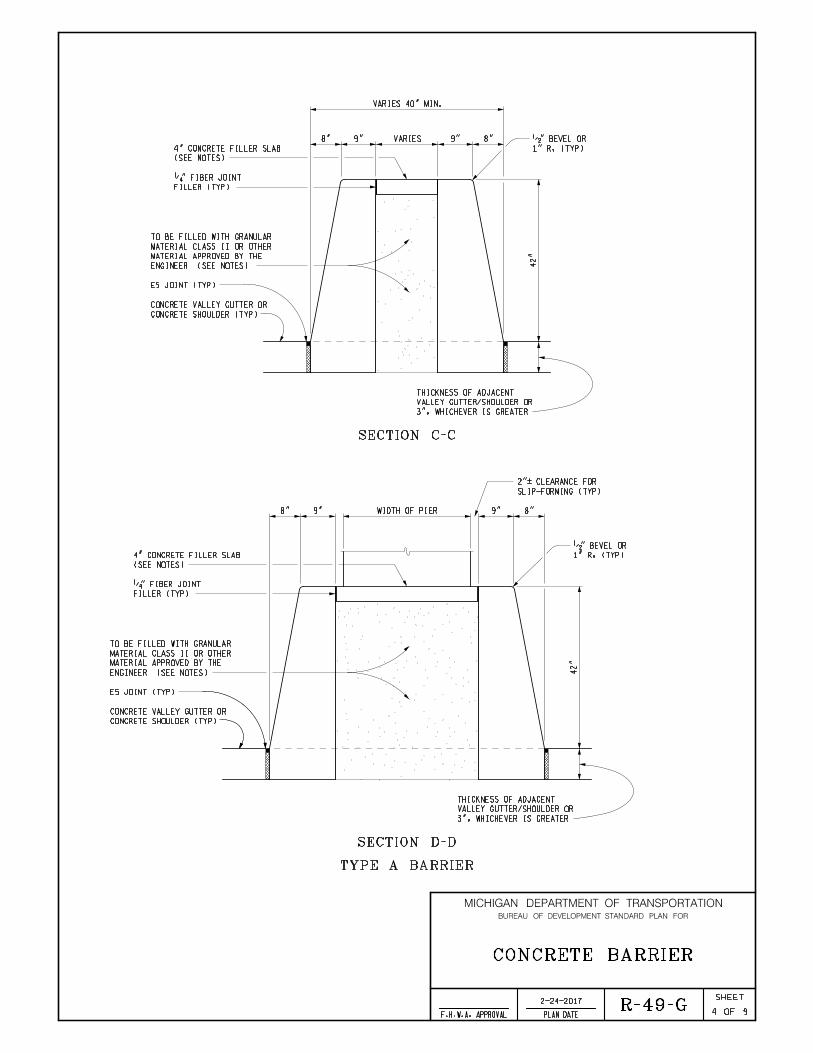
SECTION C-C
SECTION D-D
9" 9"VARIES
VARIES 40" MIN.
ENGINEER (SEE NOTES)
MATERIAL APPROVED BY THE
MATERIAL CLASS II OR OTHER
TO BE FILLED WITH GRANULAR
(SEE NOTES)
4" CONCRETE FILLER SLAB
FILLER (TYP)
‚" FIBER JOINT
8" 8"
42"
1" R, (TYP)
•" BEVEL OR
9" 9"
ENGINEER (SEE NOTES)
MATERIAL APPROVED BY THE
MATERIAL CLASS II OR OTHER
TO BE FILLED WITH GRANULAR
(SEE NOTES)
4" CONCRETE FILLER SLAB
FILLER (TYP)
‚" FIBER JOINT
WIDTH OF PIER
SLIP-FORMING (TYP)
2"< CLEARANCE FOR
R-49-G
CONCRETE BARRIER
TYPE A BARRIER
94
CONCRETE SHOULDER (TYP)
CONCRETE VALLEY GUTTER OR
E5 JOINT (TYP)
3", WHICHEVER IS GREATER
VALLEY GUTTER/SHOULDER OR
THICKNESS OF ADJACENT
CONCRETE SHOULDER (TYP)
CONCRETE VALLEY GUTTER OR
E5 JOINT (TYP)
3", WHICHEVER IS GREATER
VALLEY GUTTER/SHOULDER OR
THICKNESS OF ADJACENT
2-24-2017

MICHIGAN DEPARTMENT OF TRANSPORTATION
OF
SHEET
PLAN DATEF.H.W.A. APPROVAL
BUREAU OF DEVELOPMENT STANDARD PLAN FOR
R-49-G
CONCRETE BARRIER
PAVEMENT STENCILS IMPRINTED ‚" DEEP.
BOTH SIDES OF THE BARRIER. USE 3" TO 4"
CONSTRUCTION STATIONING SHALL BE PLACED ON
7 + 00
2'-4"
< 1"
SEE STANDARD SPECIFICATIONS
BARRIER REFLECTIVE MARKER
ELEVATION
‚" FIBER JOINT FILLER
HATCHED AREA INDICATES
TYPE B BARRIER
8'-0" TAPERED SECTION
(SEE NOTES)
20'-0" MAXIMUM BETWEEN JOINTS
CONCRETE BARRIER CONCRETE BARRIER - SPLIT
40"
6"
PLAN
E F
FE5 JOINT (TYP)
E
95
1
24
SEE EXPANSION JOINT DETAIL
AND END OF SPLIT SECTIONS
1" EXPANSION JOINT AT BEGINNING
1
24
2-24-2017

MICHIGAN DEPARTMENT OF TRANSPORTATION
OF
SHEET
PLAN DATEF.H.W.A. APPROVAL
BUREAU OF DEVELOPMENT STANDARD PLAN FOR
R-49-G
CONCRETE BARRIER
ELEVATION
‚" FIBER JOINT FILLER
HATCHED AREA INDICATES
TYPE B BARRIER
SEE EXPANSION JOINT DETAIL
AT BRIDGE PIERS
1" EXPANSION JOINT
H
HG
G
WEAKNESS JOINT
PLANE OF
FILLER (TYP)
•" FIBER JOINT
MIN.
1'-6"
AND CONCRETE FILLER WALL SLAB
BETWEEN BACK OF CONCRETE BARRIER
PLACE ‚" x 4" FIBER JOINT FILLER
SLIP-FORMING (TYP)
2"< CLEARANCE FOR
20'-0" MAXIMUM BETWEEN JOINTS 20'-0" MAXIMUM BETWEEN JOINTS
IN CONCRETE FILLER SLAB
6'-0" TYPICAL JOINT SPACING
CONCRETE BARRIER SPLIT
PLAN
96
PIER COLUMNS
OUTSIDE PIER COLUMNS
AT 10'-0" MAX. SPACING
PLACE 4" DRAIN HOLES
4" DRAIN HOLE (TYP)
1
24
1
24
E5 JOINT (TYP)
2-24-2017

MICHIGAN DEPARTMENT OF TRANSPORTATION
OF
SHEET
PLAN DATEF.H.W.A. APPROVAL
BUREAU OF DEVELOPMENT STANDARD PLAN FOR
8" 16" 8"
32"
42"
1" R, (TYP)
•" BEVEL OR
SECTION E-E
8" 16" 8"
1" R, (TYP)
•" BEVEL OR
SECTION F-F
32" MIN. - 40" MAX.
3"
MIN.
3"
MIN.
8"
(TYP)
6"
(T
YP)
8"
(TYP)
6"
(T
YP)
9"
MI
N.
9"
MI
N.
9"
MI
N.
R-49-G
CONCRETE BARRIER
97
SEE NOTES
DOWEL (TYP)
SEE NOTES
DOWEL (TYP)
E5 JOINT (TYP)
CONCRETE SHOULDER (TYP)
CONCRETE VALLEY GUTTER OR
E5 JOINT (TYP)
CONCRETE SHOULDER (TYP)
CONCRETE VALLEY GUTTER OR
42"
9"
MI
N.
9"
MI
N.
9"
MI
N.
2-24-2017

MICHIGAN DEPARTMENT OF TRANSPORTATION
OF
SHEET
PLAN DATEF.H.W.A. APPROVAL
BUREAU OF DEVELOPMENT STANDARD PLAN FOR
8" 8"
1" R, (TYP)
•" BEVEL OR
SECTION G-G
SECTION H-H
9" 9"VARIES
VARIES 40" MIN.
(SEE NOTES)
4" CONCRETE FILLER SLAB
FILLER (TYP)
‚" FIBER JOINT
8" 8"
1" R, (TYP)
•" BEVEL OR
9" 9"
ENGINEER (SEE NOTES)
MATERIAL APPROVED BY THE
MATERIAL CLASS II OR OTHER
TO BE FILLED WITH GRANULAR
(SEE NOTES)
4" CONCRETE FILLER SLAB
FILLER (TYP)
‚" FIBER JOINT
WIDTH OF PIER
SLIP-FORMING (TYP)
2"< CLEARANCE FOR
3"
MIN.
3"
MIN.
8"
(TYP)
6"
(T
YP)
8"
(TYP)
6"
(T
YP)
E5 JOINT (TYP)
R-49-G
CONCRETE BARRIER
98
SEE NOTES
DOWEL (TYP) 4" DRAIN HOLE
4" DRAIN HOLE
SEE NOTES
DOWEL (TYP)
CONCRETE SHOULDER (TYP)
CONCRETE VALLEY GUTTER OR
CONCRETE SHOULDER (TYP)
CONCRETE VALLEY GUTTER OR
ENGINEER (SEE NOTES)
MATERIAL APPROVED BY THE
MATERIAL CLASS II OR OTHER
TO BE FILLED WITH GRANULAR
E5 JOINT (TYP)
42"
9"
MI
N.
9"
MI
N.
9"
MI
N.
42"
9"
MI
N.
9"
MI
N.
9"
MI
N.
2-24-2017

MICHIGAN DEPARTMENT OF TRANSPORTATION
OF
SHEET
PLAN DATEF.H.W.A. APPROVAL
BUREAU OF DEVELOPMENT STANDARD PLAN FOR
FOR VALLEY GUTTER DETAILS, SEE STANDARD PLAN R-33-SERIES.
BARRIER REFLECTOR MARKERS SHALL MATCH COLOR OF EDGE LINE.
2) 25'-0" ON CURVES WITH A RADIUS LESS THAN 1150'.
OR MORE.
1) 5O'-0" ON TANGENT SECTIONS AND CURVES WITH A RADIUS OF 1150'
BARRIER REFLECTOR MARKERS ARE TO BE SPACED AT THE FOLLOWING INTERVALS:
ADJACENT TO THE BARRIER WALL OR THE BASE FOR THE CONCRETE BARRIER.
INCLUDED IN THE PAYMENT FOR THE VALLEY GUTTER OR SHOULDER WHICH IS
E5 LONGITUDINAL JOINT WILL NOT BE PAID FOR SEPARATELY BUT SHALL BE
OF AT LEAST 4" AND SHALL BE EDGED.
MINIMUM. PLANE OF WEAKNESS JOINTS IN THE BARRIER SHALL BE TO A DEPTH
PLANE OF WEAKNESS JOINT SPACING SHALL BE 20'-0" MAXIMUM AND 10'-0"
ALIGNED WITH EXPANSION JOINTS IN BARRIER.
FOUNDATION). PLACE 1" EXPANSION JOINTS IN 4" CONCRETE FILLER SLAB,
LIGHT STANDARD FOUNDATIONS, BRIDGE PIERS, OR ANY STRUCTURE WITH A
ON BOTH ENDS OF ALL STRUCTURES (INCLUDING SIGN SUPPORT FOUNDATIONS,
BARRIERS. ALSO PLACE 1" EXPANSION JOINTS AT SPLIT SECTIONS AND
PLACE 1" EXPANSION JOINTS AT 400' INTERVALS IN BOTH TYPE A AND TYPE B
R-49-G
CONCRETE BARRIER
99
WILL BE PAID FOR AS "CONC BARRIER BACKFILL, CIP".
THE CLASS II GRANULAR MATERIAL USED IN FILLING SPLIT BARRIER SECTIONS
"SIDEWALK, CONC, 4 INCH".
INCH". THE ‚" FIBER JOINT FILLER SHALL BE INCLUDED IN THE PAY ITEM
THE CONCRETE FILLER SLAB SHALL BE PAID FOR AS "SIDEWALK, CONC, 4
SPLIT ARE INCLUDED IN THE PAY ITEM "CONC BARRIER, SPLIT, TYPE ".
THE TAPERED SECTIONS AT THE BEGINNING AND END OF CONCRETE BARRIER,
CURVES, AND SHALL BE FREE OF HUMPS, SAGS, AND OTHER IRREGULARITIES.
WHEN CHECKED WITH A 10' STRAIGHTEDGE, EXCEPT AT GRADE CHANGES AND
THE TOP AND FACES OF THE BARRIER SHALL NOT VARY MORE THAN •" IN 10'
ATTENUATION DEVICE.
THE CLEAR ZONE, BY ENDING AT A STRUCTURE, OR BY UTILIZING AN IMPACT
TRAFFIC, SUCH AS BY CURVING IT AWAY FROM A TARGET POSITION BEYOND
BARRIER SHALL BE ENDED SO AS NOT TO PRESENT A HAZARD TO APPROACHING
ETC.).
SEPARATELY (FOR EXAMPLE: AS CONCRETE SHOULDER, CONCRETE BASE COURSE,
BASE FOR "CONCRETE BARRIER, DOUBLE FACE, TYPE B" WILL BE PAID FOR
INCLUDED IN THE PAY ITEM "CONC BARRIER, DOUBLE FACE, TYPE B". THE
SPACING MAY BE ADJUSTED TO AVOID CONFLICT WITH JOINTS. DOWELS ARE
DOWELS SHALL BE PLACED 3'-0" C-C ALONG EACH SIDE OF THE BARRIER.
THE PAY ITEM "CONC BARRIER, DOUBLE FACE, TYPE B". ON SPLIT SECTIONS,
SIDE TO SIDE (6'-0" C-C ALONG EACH SIDE). DOWELS ARE INCLUDED IN
DOWELS SHALL BE PLACED EVERY 3'-0" ALONG THE BARRIER ALTERNATING FROM
DOWEL PLACEMENT SHALL START 1'-6" FROM END OF STANDARD SECTION.
SHOULDER AND DOWELED WITH EPOXY COATED #6 DEFORMED BARS 1'-3" LONG.
PLANS, THE BARRIER SHALL BE CONSTRUCTED ON AN EXISTING BASE OR
WHEN "CONCRETE BARRIER, DOUBLE FACE, TYPE B" IS DESIGNATED ON THE
INCLUDED IN THE PAY ITEM "CONC BARRIER, DOUBLE FACE, TYPE A".
THE DOWELS, EXTRA WIDTH OF BASE, OR ANY EXTRA WORK REQUIRED WILL BE
BASE AS SPECIFIED FOR THE "CONCRETE BARRIER, DOUBLE FACE, TYPE B".
PLANS, THE BARRIER MAY BE CONSTRUCTED USING DOWELS AND A WIDENED
WHEN "CONCRETE BARRIER, DOUBLE FACE, TYPE A" IS DESIGNATED ON THE
NOTES:
2-24-2017

DEPARTMENT DIRECTOR MICHIGAN DEPARTMENT OF TRANSPORTATION
OF
SHEET
PLAN DATEF.H.W.A. APPROVALCHECKED BY:
DRAWN BY:
Michigan Department of Transportation
BUREAU OF DEVELOPMENT STANDARD PLAN FOR
APPROVED BY:
APPROVED BY:
Kirk T. Steudle
BY
PREPARED
DESIGN DIVISION
DIRECTOR, BUREAU OF FIELD SERVICES
DIRECTOR, BUREAU OF DEVELOPMENT
12'-0" 8'-0"
6'-0"6'-0"
1'-8"
6'-0"
2'-8"
1'-4"
8"
A
A
PLAN
SIDE
1'-0"
8'-0"
8"
1'-8"
BOLT CIRCLE
1'-1" DIA.
1" EXPANSION JOINT (TYP)
(SEE STANDARD PLAN R-72-SERIES)
1" EXPANSION JOINT
END THE GLARE SCREEN AT THE
IS SPECIFIED ON THE PLANS,
WHERE CONCRETE GLARE SCREEN
(SEE STANDARD PLAN R-72-SERIES)
1" EXPANSION JOINT
END THE GLARE SCREEN AT THE
IS SPECIFIED ON THE PLANS,
WHERE CONCRETE GLARE SCREEN
ELEVATION
12'-0"
TRANSITION SECTION TRANSITION SECTION
B
B
C
C
B.L.T.
W.K.P. 1 6
LIGHT STANDARD FOUNDATION
R-50-G
28'-2"
VERTICAL WALL BARRIER SECTION
D
D
TY
PE
A
BA
RRI
ER
TY
PE
B
BA
RRI
ER
AND CONDUIT
\ OF BOLT CIRCLE
3'-6"
8"
R-49-SERIES
SEE STANDARD PLAN
E5 JOINT (TYP)
6'-0"
1'-6" R
1'-8" 1'-8"8"8" 1'-4"
1" R (TYP)
•" BEVEL OR
R-33-SERIES
SEE STANDARD PLAN
GUTTER (TYP)
CONCRETE VALLEY
CONDUIT
3" DIAMETER
1'-6"
MI
N.
1'-0"
3'-6"
8"
R-49-SERIES
SEE STANDARD PLAN
E5 JOINT (TYP)
6'-0"
1'-6" R
1'-8" 1'-8"8"8" 1'-4"
1" R (TYP)
•" BEVEL OR
R-33-SERIES
SEE STANDARD PLAN
GUTTER (TYP)
CONCRETE VALLEY
CONDUIT
3" DIAMETER
1'-6"
MI
N.
(TYPE A BARRIER)
SIDE(TYPE B BARRIER)
(CONCRETE BARRIER, DOUBLE FACE)
4-21-2017

MICHIGAN DEPARTMENT OF TRANSPORTATION
OF
SHEET
PLAN DATEF.H.W.A. APPROVAL
BUREAU OF DEVELOPMENT STANDARD PLAN FOR
A1 BARS3•
"
3•
"
3'-6"
1'-0"
4•
"4•
"1'-0"
1'-0"
1'-0"
1'-1•
"1'-1•
"
8"
6" 6"
3"
IN
BA
RRI
ER
WA
LL
A1
BA
RS
AT 5
EQ
UA
L
SP
AC
ES
3"
A1
BA
RS I
N
FO
OTI
NG
3"
3"
BA
RRI
ER
WA
LL
A1
BA
RS I
N
6" 6"
12'-0"6'-0"
SHOWING STEEL REINFORCEMENT
PLAN
SHOWING STEEL REINFORCEMENT
ELEVATION
6R-50-G
2
1'-0"
6" 6"1'-0"
1'-0"
6" 6"1'-0"A2 BARS AT 6" SPACING IN FOOTING A2 BARS AT 6" SPACING IN FOOTING
A2 BARS AT 6" SPACING IN FOOTING A2 BARS AT 6" SPACING IN FOOTING
D BARS AT 6" SPACING IN BARRIER WALL D BARS AT 6" SPACING IN BARRIER WALL
D BARS AT 6" SPACING IN BARRIER WALL D BARS AT 6" SPACING IN BARRIER WALL
LIGHT STANDARD FOUNDATION(CONCRETE BARRIER, DOUBLE FACE)
4-21-2017

MICHIGAN DEPARTMENT OF TRANSPORTATION
OF
SHEET
PLAN DATEF.H.W.A. APPROVAL
BUREAU OF DEVELOPMENT STANDARD PLAN FOR
8" 8"1'-4"
2'-8"
3'-6"
SECTION A-A
1" R (TYP)
•" BEVEL OR
8" 8"1'-4"
2'-8"
3'-6"
SECTION A-A
1" R (TYP)
•" BEVEL OR
(TYPE A BARRIER)
(TYPE B BARRIER)
3"
MIN.
SEE STANDARD PLAN R-33-SERIES
CONCRETE VALLEY GUTTER (TYP)
SEE STANDARD PLAN R-33-SERIES
CONCRETE VALLEY GUTTER (TYP)
SEE STANDARD PLAN R-49-SERIES
E5 JOINT (TYP)
MI
N.
9"
8"
(TYP)
6"
(T
YP)
DOWEL (TYP)
SEE STANDARD PLAN R-49-SERIES
E5 JOINT (TYP)
6R-50-G
3
LIGHT STANDARD FOUNDATION(CONCRETE BARRIER, DOUBLE FACE)
4-21-2017

MICHIGAN DEPARTMENT OF TRANSPORTATION
OF
SHEET
PLAN DATEF.H.W.A. APPROVAL
BUREAU OF DEVELOPMENT STANDARD PLAN FOR
2'-8"
1'-4" TO 2'-8"
VARIES
SECTION B-B
1" R (TYP)
•" BEVEL OR
3'-6"
FROM SINGLE SLOPE SHAPE TO VERTICAL WALL
UNIFORMLY TRANSITION THE BARRIER FACES
2'-8"
1'-4" TO 2'-8"
VARIES
1" R (TYP)
•" BEVEL OR
3'-6"
(TYPE A BARRIER)
SECTION B-B(TYPE B BARRIER)
FROM SINGLE SLOPE SHAPE TO VERTICAL WALL
UNIFORMLY TRANSITION THE BARRIER FACES
SEE STANDARD PLAN R-33-SERIES
CONCRETE VALLEY GUTTER (TYP)
SEE STANDARD PLAN R-33-SERIES
CONCRETE VALLEY GUTTER (TYP)
SEE STANDARD PLAN R-49-SERIES
E5 JOINT (TYP)
SEE STANDARD PLAN R-49-SERIES
E5 JOINT (TYP)
6"
(T
YP)
MI
N.
9"
8"
(TYP)
DOWEL (TYP)
6R-50-G
4
3" TO 0 (TYP)
* VARIES
OVER THE LENGTH OF THE TRANSITION SECTION
TO FLUSH WITH THE VERTICAL WALL BARRIER SECTION
THE FACE OF THE CONCRETE BARRIER, DOUBLE FACE
* UNIFORMLY TRANSITION E5 JOINT FROM 3" OUTSIDE
LIGHT STANDARD FOUNDATION(CONCRETE BARRIER, DOUBLE FACE)
4-21-2017

MICHIGAN DEPARTMENT OF TRANSPORTATION
OF
SHEET
PLAN DATEF.H.W.A. APPROVAL
BUREAU OF DEVELOPMENT STANDARD PLAN FOR
6R-50-G
5
GROUNDING ROD
8"
1'-6"
1'-6"
\ OF ANCHOR BOLT TIES
ANCHOR BOLT (TYP)
CONDUIT
3" DIAMETER
2'-8"
1" R (TYP)
•" BEVEL OR
3"
3"
A1
BA
RS
AT 5
EQ
UA
L
SP
AC
ES
3•
"
3•
"
1'-0"
4•" 4•"1'-0" 1'-0"1'-1•"1'-1•" 1'-0"
A1 BARS
SEE STANDARD PLAN R-33-SERIES
CONCRETE VALLEY GUTTER (TYP)
SEE STANDARD PLAN R-49-SERIES
E5 JOINT (TYP)
3" 3"
SECTION C-C
A2 BARS AT 6" SPACING
2'-8"
1" R (TYP)
•" BEVEL OR
3"
3"
D BARS AT 6" SPACING
A1
BA
RS
AT 5
EQ
UA
L
SP
AC
ES
3•
"
3•
"
1'-0"
4•" 4•"1'-0" 1'-0"1'-1•"1'-1•" 1'-0"
A1 BARS
SEE STANDARD PLAN R-33-SERIES
CONCRETE VALLEY GUTTER (TYP)
SEE STANDARD PLAN R-49-SERIES
E5 JOINT (TYP)
3" 3"
SECTION D-D
A2 BARS AT 6" SPACING
1'-6" SLACK ABOVE TOP OF BARRIER.
AS SPECIFIED IN THE STANDARD SPECIFICATIONS. LEAVE
CONNECT THE GROUNDING CABLE TO THE GROUNDING ROD
LIGHT STANDARD FOUNDATION(CONCRETE BARRIER, DOUBLE FACE)
4-21-2017

MICHIGAN DEPARTMENT OF TRANSPORTATION
OF
SHEET
PLAN DATEF.H.W.A. APPROVAL
BUREAU OF DEVELOPMENT STANDARD PLAN FOR
BARSIZE
BARLENGTH
REQUIRED
NUMBER
(LBS)
WEIGHT
A1
A2
#5
#5
11'-6"
5'-6"
24
44
288
TOTAL WEIGHT OF STEEL = 730 LBS
STEEL REINFORCEMENT (EPOXY COATED)
252
D #4 6'-5" 44 190
4'-9"
D BAR
10"
(TYP)
6R-50-G
6
LENGTH
A BAR
MI
N.
2•
"
5•
"
MI
N.
2•
"
MI
N.
PR
OJ
EC
TI
ON
5•
"
1‚" DIAMETER STUD
FLUSH WITH TOP OF BARRIER
•" THICK WASHER (TYP.)
HEAVY HEX NUT (TYP.)
3"
MI
N.
TH
RE
AD
S
4'-2"
5…"
HEAT BEND 90° < 5°
R= 1"MIN. 3" MAX.
ANCHOR BOLT DETAIL
CONCRETE QUANTITIES
FOOTING 2.7 CYD
(TYPE A)
TRANSITION SECTIONS
4.9 CYD
5.9 CYD
6.2 CYD
LIGHT STANDARD FOUNDATION(CONCRETE BARRIER, DOUBLE FACE)
(TYPE B)
TRANSITION SECTIONS
VERTICAL WALL SECTION
4-21-2017
MATERIAL AS THE ANCHOR NUTS.
COUPLING MUST BE OF THE SAME
THIS PLAN.
TO THE STANDARD SPECIFICATIONS UNLESS OTHERWISE SPECIFIED ON
MATERIALS FOR THE ELECTRICAL GROUNDING SYSTEM SHALL BE ACCORDING
APPLICABLE R-33-SERIES.
WORK THIS STANDARD WITH STANDARD PLAN R-49-SERIES AND WHEN
PLAN.
STANDARD FOUNDATION SHALL BE CONSTRUCTED AS DETAILED ON THIS
THE CONCRETE VALLEY GUTTER USED IN CONJUNCTION WITH THE LIGHT
TEMPLATE.
AT THE PROPER HEIGHT WITH THE ƒ" PLYWOOD (OR APPROVED EQUAL)
CAREFULLY SET AND HELD VERTICAL AT THE CORRECT LOCATION AND
(OR APPROVED EQUAL) TEMPLATE. THE ANCHOR BOLT BASKET SHALL BE
CIRCLES (OR APPROVED EQUAL) ALONG WITH SECURING A ƒ" PLYWOOD
BOLTS SHALL BE TIED TOGETHER INTO A BASKET BY WELDING #6 BAR
PRIOR TO BEING APPROVED FOR SHIPMENT, EACH SET OF FOUR ANCHOR
CURRENT STANDARD SPECIFICATIONS.
ANCHOR BOLTS, NUTS, AND WASHERS SHALL BE ACCORDING TO THE
1" RADIUS.
ALL EXPOSED EDGES ON THE BARRIER SHALL HAVE A •" BEVEL OR
"SINGLE SLOPE" SHAPE.
THE SIDE CONFIGURATION SPECIFIED ON THIS PLAN CONFORMS TO THE
NOTES:

DEPARTMENT DIRECTOR MICHIGAN DEPARTMENT OF TRANSPORTATION
OF
SHEET
PLAN DATEF.H.W.A. APPROVALCHECKED BY:
DRAWN BY:
Michigan Department of Transportation
BUREAU OF DEVELOPMENT STANDARD PLAN FOR
APPROVED BY:
APPROVED BY:
Kirk T. Steudle
BY
PREPARED
DESIGN DIVISION
DIRECTOR, BUREAU OF FIELD SERVICES
DIRECTOR, BUREAU OF DEVELOPMENT
8"1'-4" 8"8"8"
8"
1'-2"
3'-6"
R-49-SERIES
SEE STANDARD PLAN
E5 JOINT (TYP)
R-33-SERIES
SEE STANDARD PLAN
GUTTER (TYP)
CONCRETE VALLEY
1" R (TYP)
•" BEVEL OR
8"
1'-2"
3'-6"
R-49-SERIES
SEE STANDARD PLAN
E5 JOINT (TYP)
8"1'-4" 8"8"8"
1" R (TYP)
•" BEVEL OR
R-33-SERIES
SEE STANDARD PLAN
GUTTER (TYP)
CONCRETE VALLEY
K J K
N16'-0"
TRANSITION SECTION
16'-0"
TRANSITION SECTION2'-8"
GU
TT
ER
VA
LL
EY
CO
NC
RE
TE
GU
TT
ER
VA
LL
EY
CO
NC
RE
TE
2'-
0"
2'-
0"
VALLEY GUTTER (TYP)
FLOW LINE IN CONCRETE
MAINTAIN UNIFORM DEPTH OF
SUPPORT FOUNDATION (TYP)
SIDE APPROACHING THE SIGN
PLACE GLARE SCREEN ON THE
EDGE OF SHOULDER
EDGE OF SHOULDER
JOINT (TYP)
CONTRACTION
ANCHOR BOLTS (TYP)
SEE STANDARD PLAN R-49-SERIES
E5 JOINT (TYP)
(SEE STANDARD PLAN R-76-SERIES)
1" EXPANSION JOINT
END THE GLARE SCREEN AT THE
IS SPECIFIED ON THE PLANS,
WHERE CONCRETE GLARE SCREEN
PLAN
SIGN SUPPORT SECTION
L = LENGTH OF SIGN SUPPORT FOUNDATION
JOINT (TYP)
1 " EXPANSION
(SEE STANDARD PLAN R-76-SERIES)
1" EXPANSION JOINT
END THE GLARE SCREEN AT THE
IS SPECIFIED ON THE PLANS,
WHERE CONCRETE GLARE SCREEN
BA
RRI
ER
TY
PE
A
BA
RRI
ER
TY
PE
B
55'-2"
58'-2"
C
D
TYPE
SUPPORTJ K L N
6'-11"
8'-8" 8'-8"
8'-0•"
DIMENSIONS FOR SIGN SUPPORT FOUNDATIONS
23'-0"
26'-0"
GUTTER
VALLEY
CONCRETE
TOP OF
ELEVATION
10'-0" 10'-0"
(TYPE B BARRIER)(TYPE A BARRIER)
SIDE SIDE
N
SIGN SUPPORT SECTION
A B
A B
C
C
6R-51-E
1
(CONCRETE BARRIER, DOUBLE FACE)
SIGN SUPPORT FOUNDATION
4-21-2017
OF TRAVEL
DIRECTION
OF TRAVEL
DIRECTION

MICHIGAN DEPARTMENT OF TRANSPORTATION
OF
SHEET
PLAN DATEF.H.W.A. APPROVAL
BUREAU OF DEVELOPMENT STANDARD PLAN FOR
10'-0"
6"
6" 6"
D BARS 50 SPACES AT 6" = 25'-0" IN BARRIER WALL FOR SIGN SUPPORT D6" 6"
D BARS 44 SPACES AT 6" = 22'-0" IN BARRIER WALL FOR SIGN SUPPORT C
6"
6" 6"
6" 6"
A2 BARS 44 SPACES AT 6" = 22'-0" IN FOOTING FOR SIGN SUPPORT C
A2 BARS 50 SPACES AT 6" = 25'-0" IN FOOTING FOR SIGN SUPPORT D
3"
3"
WA
LL
IN
BA
RRI
ER
A1
BA
RS
6"
8"
12"
12"
12"
BA
RRI
ER
WA
LL
A1
BA
RS I
N
6" 6"
6" 6"
A2 BARS 44 SPACES AT 6" = 22'-0" IN FOOTING FOR SIGN SUPPORT C
A2 BARS 50 SPACES AT 6" = 25'-0" IN FOOTING FOR SIGN SUPPORT D
6" 6"
D BARS 50 SPACES AT 6" = 25'-0" IN BARRIER WALL FOR SIGN SUPPORT D6" 6"
D BARS 44 SPACES AT 6" = 22'-0" IN BARRIER WALL FOR SIGN SUPPORT C
A1 BARS
1'-2"
8"
3'-6"
4"
4"
SHOWING STEEL REINFORCEMENT
PLAN
SHOWING STEEL REINFORCEMENT
ELEVATION
6R-51-E
2
(CONCRETE BARRIER, DOUBLE FACE)
SIGN SUPPORT FOUNDATION
4-21-2017
A1
BA
RS
AT 1'-6"
SP
ACI
NG I
N
FO
OTI
NG

MICHIGAN DEPARTMENT OF TRANSPORTATION
OF
SHEET
PLAN DATEF.H.W.A. APPROVAL
BUREAU OF DEVELOPMENT STANDARD PLAN FOR
6R-51-E
3
(CONCRETE BARRIER, DOUBLE FACE)
SIGN SUPPORT FOUNDATION
(TYPE B BARRIER)
TRANSITION SECTION PLAN
CONCRETE BARRIER, DOUBLE FACE 16'-0"
TRANSITION SECTION
1'-4"
8"
8"
3"
VA
LL
EY
GU
TT
ER
CO
NC
RE
TE
2'-0"
2'-8"
VA
LL
EY
GU
TT
ER
CO
NC
RE
TE
2'-0"
SUPPORT FOUNDATION (TYP)
SIDE APPROACHING THE SIGN
PLACE GLARE SCREEN ON THE
EDGE OF SHOULDER
EDGE OF SHOULDER
JOINT (TYP)
1 " EXPANSION
JOINT (TYP)
CONTRACTION
SEE STANDARD PLAN R-49-SERIES
E5 JOINT (TYP)
THE LENGTH OF THE TRANSITION SECTION
TO FLUSH WITH THE SIGN SUPPORT SECTION OVER
THE FACE OF THE CONCRETE BARRIER, DOUBLE FACE
UNIFORMLY TRANSITION E5 JOINT FROM 3" OUTSIDE
4-21-2017
VALLEY GUTTER (TYP)
FLOW LINE IN CONCRETE
MAINTAIN UNIFORM DEPTH OF
SIGN SUPPORT SECTION
8" 1'-4"
2'-8"
8"
SEE STANDARD PLAN R-49-SERIES
E5 JOINT (TYP)
1" R (TYP)
•" BEVEL OR
3'-6"
SECTION A-A(TYPE A BARRIER)
SEE STANDARD PLAN R-33-SERIES
CONCRETE VALLEY GUTTER (TYP)

MICHIGAN DEPARTMENT OF TRANSPORTATION
OF
SHEET
PLAN DATEF.H.W.A. APPROVAL
BUREAU OF DEVELOPMENT STANDARD PLAN FOR
6R-51-E
4
(CONCRETE BARRIER, DOUBLE FACE)
SIGN SUPPORT FOUNDATION
4-21-2017
8" 1'-4"
2'-8"
8"1" R (TYP)
•" BEVEL OR
3'-6"
3"
MIN.
SEE STANDARD PLAN R-49-SERIES
E5 JOINT (TYP)DOWEL (TYP)8"
(TYP)
SEE STANDARD PLAN R-33-SERIES
CONCRETE VALLEY GUTTER (TYP)
MI
N.
9"
6"
(T
YP)
SECTION A-A(TYPE B BARRIER)
1'-4" TO 2'-8"
VARIES
1" R (TYP)
•" BEVEL OR
2'-8" TO 4'-0"
VARIES
2'-0" (TYP)
FLOW LINE
SEE STANDARD PLAN R-49-SERIES
E5 JOINT (TYP)
3'-6"
SECTION B-B(TYPE A BARRIER)
1'-4" TO 2'-8"
VARIES
1" R (TYP)
•" BEVEL OR
2'-8" TO 4'-0"
VARIES
3'-6"
DOWEL (TYP)8"
(TYP)
6"
(T
YP)
MI
N.
9"
SEE STANDARD PLAN R-49-SERIES
E5 JOINT (TYP)
SECTION B-B(TYPE B BARRIER)
3" TO 0 (TYP)
* VARIES
THE LENGTH OF THE TRANSITION SECTION
TO FLUSH WITH THE SIGN SUPPORT SECTION OVER
THE FACE OF THE CONCRETE BARRIER, DOUBLE FACE
* UNIFORMLY TRANSITION E5 JOINT FROM 3" OUTSIDE
2'-0" (TYP)
FLOW LINE
4
21
4
21
4
21
4
21
THE TRANSITION SECTION.
OF THE BARRIER THROUGHOUT THE ENTIRE LENGTH OF
MAINTAIN CONSTANT BARRIER SLOPE ON BOTH SIDES
NOTE:

6" 6"
4"
6"
4"
A2 BARS AT 6" SPACING
8"
12"
12"
12"
6"
A1
BA
RS I
N
BA
RRI
ER
WA
LL
1" R (TYP)
•" BEVEL OR
D BARS AT 6" SPACING
3" 3"
E E
ANCHOR BOLT (TYP)
FLOW LINE
2'-0" (TYP)
SEE STANDARD PLAN R-49-SERIES
E5 JOINT (TYP)
#6 BAR CIRCLE (TYP)
MICHIGAN DEPARTMENT OF TRANSPORTATION
OF
SHEET
PLAN DATEF.H.W.A. APPROVAL
BUREAU OF DEVELOPMENT STANDARD PLAN FOR
2'-8" 8"8"
4'-0"
SECTION C-C
F
F
E E
ANCHOR BOLT ALIGNMENT
ANCHOR BOLTS
TYPE
SUPPORT
SIGN
C
D
E F
9•"
9•"
2‚"
3"
ANCHOR BOLT ALIGNMENT
DIMENSIONS FOR
5'-3‚
"
5‚"
HEAT BEND 90° < 5°
R= 1"MIN. 3" MAX.
3"
MI
N.
2†
"8"
PR
OJ
EC
TI
ON
HEAVY HEX NUT (TYP)
1•" DIAMETER ANCHOR BOLT
WASHER (TYP)
TOP OF BARRIER
TH
RE
AD
S
8•
"
MI
N.
2'-7"
MUST BE SECURED IN PLACE.
ƒ" PLYWOOD TEMPLATE OR APPROVED EQUAL
TO ANCHOR BOLTS TO HOLD ALIGNMENT. A
#6 BAR CIRCLE OR APPROVED EQUAL WELDED
1•" DIAMETER ANCHOR BOLT
ANCHOR BOLT DETAIL6
R-51-E5
(CONCRETE BARRIER, DOUBLE FACE)
SIGN SUPPORT FOUNDATION
4-21-2017
A1 BARS AT 1'-6" SPACING IN FOOTING

MICHIGAN DEPARTMENT OF TRANSPORTATION
OF
SHEET
PLAN DATEF.H.W.A. APPROVAL
BUREAU OF DEVELOPMENT STANDARD PLAN FOR
BARSIZE
BARLENGTH
REQUIRED
NUMBER
(LBS)
WEIGHT
A1
A2
#5
#5
22'-2"
9'-2"
22
90
509
STEEL REINFORCEMENT (EPOXY COATED)
861
D #4 5'-6•" 90 334
TOTAL WEIGHT OF STEEL = 1,704 LBS
BARSIZE
BARLENGTH
REQUIRED
NUMBER
(LBS)
WEIGHT
A1
A2
#5
#5
25'-2"
9'-2"
22 578
976
D #4 5'-6•" 378
102
102
TOTAL WEIGHT OF STEEL = 1,932 LBS
(TYPE B)
SECTIONS
TRANSITION
SECTION
SUPPORT
SIGN
(TYPE A)
SECTIONS
TRANSITION
FOOTING
SUPPORT
SIGN
TYPE
SUPPORT
SIGN
14.5 CYD
14.5 CYD
13.7 CYD
13.7 CYD
12.3 CYD10.0 CYDC
13.9 CYD11.3 CYDD
CONCRETE QUANTITIES
3'-1"
D BAR
10‚"
LENGTH
A BAR
1'-6•
"
7‚"
3'-1ƒ"
6R-51-E
6
(CONCRETE BARRIER, DOUBLE FACE)
SIGN SUPPORT FOUNDATION
4-21-2017
SIGN SUPPORT TYPE C SIGN SUPPORT TYPE D
APPLICABLE R-33-SERIES AND R-76-SERIES.
WORK THIS STANDARD WITH STANDARD PLAN R-49-SERIES AND WHEN
IN FULL FOR ALL WORK AND MATERIALS.
THE CONTRACT UNIT PRICE PER LINEAR FEET, WHICH INCLUDES PAYMENT
PLAN, AND INCLUDED IN THEIR RESPECTIVE ITEMS AND PAID FOR AT
SUPPORT FOUNDATION SHALL BE CONSTRUCTED AS DETAILED ON THIS
THE CONCRETE GLARE SCREEN USED IN CONJUNCTION WITH THE SIGN
MODIFICATIONS TO THE CONCRETE VALLEY GUTTER AND LOCATION OF
BEING PLACED AS SPECIFIED ON THIS PLAN.
ENDS WITH THE 1" EXPANSION JOINTS USED TO GAP FOR STRUCTURES
SIGN SUPPORT FOUNDATION INCLUDES THE TRANSITION SECTION ON BOTH
BEING APPROVED FOR SHIPPING (SEE ANCHOR BOLT DETAIL).
A ƒ" PLYWOOD (OR APPROVED EQUAL) TEMPLATE IN PLACE PRIOR TO
WITH #6 BAR CIRCLES (OR APPROVED EQUAL) ALONG WITH SECURING
OF FOUR BOLTS SHALL BE TIED TOGETHER BY WELDING INTO A BASKET
(OR APPROVED EQUAL) TEMPLATE UNTIL CONCRETE IS SET. EACH SET
CORRECT LOCATION AND AT THE PROPER ELEVATION WITH ƒ" PLYWOOD
ANCHOR BOLTS SHALL BE CAREFULLY SET AND HELD VERTICAL AT THE
CURRENT STANDARD SPECIFICATIONS.
ANCHOR BOLTS, NUTS, AND WASHERS SHALL BE ACCORDING TO THE
RADIUS.
ALL EXPOSED EDGES ON THE BARRIER SHALL HAVE A •" BEVEL OR 1"
"SINGLE SLOPE" SHAPE.
THE SIDE CONFIGURATION SPECIFIED ON THIS PLAN CONFORMS TO THE
NOTES:

CONCRETE BARRIER, SINGLE FACE
SECTION B - B SECTION C - C
A
A
BC
C
(AT CIRCULAR COLUMN)
CONCRETE BARRIER, SINGLE FACE
(AT SQUARE COLUMN OR ABUTMENT)
CONCRETE BARRIER, SINGLE FACE
B
CONCRETE BARRIER, SINGLE FACE, TYPE A
(IN LINE WITH BRIDGE COLUMNS OR ABUTMENT)
SECTION A - A
R-54-I3-22-2017B.L.T.
W.K.P. 1 4
2'-4"
< 1"
2'-4"
< 1"
2'-4"
< 1"
3'-6"
8"
*
VARIES
3'-6"
*
ON PLANS
SPECIFIED
SLOPE AS
STANDARD SPECIFICATIONS
MARKER SEE CURRENT
BARRIER REFLECTOR
FILLER WALL
3"
NA
RR
OW
SH
OU
LD
ER
CONCRETE BARRIER, SINGLE FACE
(NORMAL SECTION)
CONTRACTION JOINT
CONCRETE BARRIER, SINGLE FACE, TYPE A
EDGE OF TRAVELED LANE (PAINT LINE)
1
12'-0" TRANSITION SECTION
(L
ES
S
TH
AN 12'-0")
1" EXPANSION JOINT
12'-0" TRANSITION SECTION
*3'-6"
OR ABUTMENT
BRIDGE COLUMN
8"1'-4"
2'-0"
(SEE PLANS)
SLOPE PAVING
GROUND SURFACE
ORIGINAL
OR ABUTMENT
COLUMN
BRIDGE
FOR MAXIMUM FLARE RATE
SEE CHART
FILLER WALL
COLUMN
BRIDGE
1" EXPANSION JOINT
STANDARD SPECIFICATIONS
MARKER SEE CURRENT
BARRIER REFLECTOR
(SEE NOTES)
UNDERDRAIN
(SEE NOTES)
UNDERDRAIN
(SEE NOTES)
UNDERDRAIN E5 JOINT
E5 JOINT E5 JOINT
DEPARTMENT DIRECTOR MICHIGAN DEPARTMENT OF TRANSPORTATION
OF
SHEET
PLAN DATEF.H.W.A. APPROVALCHECKED BY:
DRAWN BY:
Michigan Department of Transportation
BUREAU OF DEVELOPMENT STANDARD PLAN FOR
APPROVED BY:
APPROVED BY:
Kirk T. Steudle
BY
PREPARED
DESIGN DIVISION
DIRECTOR, BUREAU OF FIELD SERVICES
DIRECTOR, BUREAU OF DEVELOPMENT
1'-4"VARIES 8" 16" 8"
32"
1" RADIUS (TYP)
•" BEVEL OR
3" WHICHEVER IS GREATER
VALLEY GUTTER/SHOULDER OR
* THICKNESS OF ADJACENT
ON PLANS
SPECIFIED
SLOPE AS
STANDARD SPECIFICATIONS
MARKER SEE CURRENT
BARRIER REFLECTOR
BARRIER FACE TO VERTICAL
UNIFORMLY TRANSITION

CONCRETE BARRIER, SINGLE FACE, TYPE B
(IN LINE WITH BRIDGE COLUMNS OR ABUTMENT)
(IN FRONT OF BRIDGE COLUMNS OR ABUTMENTS)
D
D
E
E
PLAN VIEW
SECTION E - ESECTION D - D
CONCRETE BARRIER, SINGLE FACE, TYPE B (SHOWN)
CONCRETE BARRIER, SINGLE FACE
2 4
* EPOXY COATED DOWEL BAR
BRIDGE COLUMNS
TOE OF SLOPE
CONCRETE BARRIER, SINGLE FACE
EDGE OF TRAVELED LANE (PAINT LINE)
1
12'-0"
MA
X.
8'-0"
MI
N.
TO
E
OF
SL
OP
E
7'-0" FOR 1:2 SLOPE
FOR MAXIMUM FLARE RATE
SEE CHART
NONREINFORCED CONCRETE SHOULDER (AS SPECIFIED ON PLANS)
8"
9"
3'-6"
(AS SPECIFIED ON PLANS)
8'-0" MIN. 12'-0" MAX.
OR ABUTMENT
BRIDGE COLUMN
OR ABUTMENT AND BARRIER
BETWEEN BRIDGE COLUMN
1" FIBER JOINT FILLER
2'-4"
+ 1"
DOWEL BAR
* EPOXY COATED
AVOID ANY CONFLICT.
FROM ANY TRANSVERSE JOINT: SPACING MAY BE ADJUSTED TO
OF THE BARRIER. SPACING SHALL BE NO CLOSER THAN 1'-6"
CONCRETE SHOULDER STARTING AT 1'-6" FROM THE BEGINNING
LONG SPACED AT 1'-6" WITH 6" EMBEDMENT IN FOOTING OR
EPOXY COATED DOWEL BARS SHALL BE #6 DEFORMED BARS 1'-3"
* NOTE:
(SEE NOTES)
UNDERDRAIN
BD JOINT
14'-0"
LA
NE
SH
OW
N
(P
AI
NT
LI
NE)
ED
GE
OF
TR
AV
EL
ED
LA
NE
12'-0"
LA
NE
SH
OW
N
(P
AI
NT
LI
NE)
ED
GE
OF
TR
AV
EL
ED
LA
NE
BD JOINT
9"
3"
E5 JOINT
E5 JOINT
R-54-H3-22-2017
MICHIGAN DEPARTMENT OF TRANSPORTATION
OF
SHEET
PLAN DATEF.H.W.A. APPROVAL
BUREAU OF DEVELOPMENT STANDARD PLAN FOR
2'-4"
< 1"
3'-6"
ON PLANS
SPECIFIED
SLOPE AS
STANDARD SPECIFICATIONS
MARKER SEE CURRENT
BARRIER REFLECTOR
8" 16" 8"
32"
1" RADIUS (TYP)
•" BEVEL OR
SPECIFI
ED ON
PLANS
1:2
OR AS
16" 8"
32"
SPECIFICATIONS
CURRENT STANDARD
MARKER SEE
BARRIER REFLECTOR
3"3"
16" 16"
32"

CONCRETE BARRIER, SINGLE FACE, TYPE C
(IN LINE WITH BRIDGE COLUMNS OR ABUTMENT)
FLARE CHART
CONCRETE BARRIER, SINGLE FACE, TYPE C
(WITH GUARDRAIL ENDING)
ELEVATION VIEW
CROSS SECTION VIEW
POST FOOTING
SECTION F - F
CONCRETE BARRIER, SINGLE FACE
F F
3'-0" MINIMUM8'-0" CENTERS (TYP.)
POST FOOTING (TYP.)
1'-0" DIAMETER CONCRETE
GUARDRAIL ANCHORAGE, BRIDGE, DETAIL T2 WITH GUARDRAIL APPROACH TERMINAL TYPE 1B
* GUARDRAIL ANCHORAGE, BRIDGE, DETAIL T1 WITH GUARDRAIL APPROACH TERMINAL TYPE 1T OR
1:20
1:18
1:16MAXIMUM 15' OFFSET.
DESIGN SPEED. THE FLARE RATE OF THE CONCRETE BARRIER IS LIMITED BY ITS LENGTH AND
THE MAXIMUM FLARE RATE IS THE LARGEST ALLOWABLE DEPARTURE ANGLE FOR THE SPECIFIED
TRANSITION CONCRETE BARRIER, SINGLE FACE TO MATCH SHAPE OF BRIDGE BARRIER RAILING.
SH
OU
LD
ER
1
EXPANSION JOINT
SEE CHART
FOR MAXIMUM FLARE RATE,
CONCRETE BARRIER, SINGLE FACE, TYPE C
(SEE STANDARD PLAN R-61-SERIES)
* GUARDRAIL APPROACH TERMINAL
(SEE STANDARD PLAN R-67-SERIES)
* GUARDRAIL ANCHORAGE, BRIDGE
EDGE OF TRAVELED LANE (PAINT LINE)
CONCRETE BARRIER, SINGLE FACE
FLARE RATE SAME AS
(SEE STANDARD PLAN R-32-SERIES)
BRIDGE APPROACH CURB & GUTTER DETAIL 1, 2, OR 3
(115' MINIMUM)
15'
MA
X.
RAILING
BRIDGE
< 1"
2'-4"
SHOULDER
TOP OF
JOINT SEE NOTES
DIA.
1'-0" DIA.
6‚"
(6) #3 TIE BARS
(5) #6 BARS
SEE CURRENT STANDARD SPECIFICATIONS
BARRIER REFLECTOR MARKER
1" RADIUS (TYP.)
•" BEVEL OR
8"
(P
AI
NT
LI
NE)
ED
GE
OF
TR
AV
EL
ED
LA
NE
3"
6"
5"
(5) #6 BARS 7'-0" LONG
SEE SECTION F - F
EQUALLY SPACED
(6) #3 TIE BARS
OR AS SPECIFIED ON PLANS
1:2 SLOPE
STANDARD SPECIFICATIONS
MARKER SEE CURRENT
BARRIER REFLECTOR
1:14
1:12
1:10
1:8
FLARE
MAXIMUM
(MPH)
DESIGN SPEED
70
60
55
50
45
40
30
3 4
DISTANCE AS SPECIFIED ON PLANS
R-54-I3-22-2017
MICHIGAN DEPARTMENT OF TRANSPORTATION
OF
SHEET
PLAN DATEF.H.W.A. APPROVAL
BUREAU OF DEVELOPMENT STANDARD PLAN FOR
8" 16"
2'-4"
< 1"
3'-6"
ON 8'-0" CENTERS FILLED WITH CONCRETE
1'-0" DIAMETER HOLE x 6'-0" DEEP

CURVES, AND SHALL BE FREE OF HUMPS, SAGS, AND OTHER IRREGULARITIES.
WHEN CHECKED WITH A 10' STRAIGHTEDGE, EXCEPT AT GRADE CHANGES AND
THE TOP AND FACES OF THE BARRIER SHALL NOT VARY MORE THAN •" IN 10'
IN THE SIDE SLOPE.
IN A CUT SECTION, THE CONCRETE BARRIER SHALL BE ENDED BY BURYING IT
2•" DEEP AND SHALL BE EDGED.
PLANE OF WEAKNESS JOINTS IN THE CONCRETE BARRIER SHALL BE AT LEAST
THE CONCRETE BARRIER.
JOINTS IN THE CONCRETE FOOTING SHALL COINCIDE WITH THE JOINTS IN
R-32-SERIES.
SPECIFIED ON THE PLANS AND CONSTRUCTED ACCORDING TO STANDARD PLAN
APPROACH CURB & GUTTER WILL BE EITHER DETAIL 1, 2, OR 3, AS
BE BUILT ACCORDING TO STANDARD PLAN R-61-SERIES. THE BRIDGE
TO STANDARD PLAN R-67-SERIES. THE GUARDRAIL APPROACH TERMINAL SHALL
TERMINAL TYPE 1B. THE GUARDRAIL ANCHORAGES SHALL BE BUILT ACCORDING
OR GUARDRAIL ANCHORAGE, BRIDGE, DETAIL T2 AND GUARDRAIL APPROACH
ANCHORAGE, BRIDGE, DETAIL T1 AND GUARDRAIL APPROACH TERMINAL TYPE 1T
IN FILL SECTIONS, THE CONCRETE BARRIER SHALL BE ENDED WITH GUARDRAIL
CONCRETE BARRIER, SINGLE FACE
BARRIER REFLECTOR MARKERS SHALL MATCH COLOR OF EDGE LINE.
THE SHOULDER.
OF WEAKNESS JOINT SPACING SHALL COINCIDE WITH CONTRACTION JOINTS IN
MINIMUM, EXCEPT WHEN THE BARRIER IS ON A CONCRETE SHOULDER. PLANE
PLANE OF WEAKNESS JOINT SPACING SHALL BE 20' MAXIMUM AND 10'
SHOULD BE ADJUSTED TO MATCH EXPANSION JOINTS IN THE SHOULDER.
OR ANY STRUCTURE WITH A FOUNDATION). LOCATION OF EXPANSION JOINTS
(INCLUDING SIGN SUPPORTS, LIGHT STANDARD FOUNDATIONS, BRIDGE PIERS,
400' INTERVALS. ALSO PLACE 1" EXPANSION JOINTS AT STRUCTURES
PLACE 1" EXPANSION JOINTS IN THE CONCRETE BARRIER AT APPROXIMATELY
44R-54-I3-22-2017
IT. THE REMAINDER OF THE FILL CAN BE TYPICAL BACKFILL MATERIAL.
MATERIAL MUST BE PLACED AROUND THE UNDERDRAIN AND AT LEAST 12" ABOVE
FOUNDATION UNDERDRAIN WRAPPED WITH GEOTEXTILE. CLASS IIAA GRANULAR
ELEVATION OF THE TOP OF SHOULDER, IS A MINIMUM 4" DIAMETER
THE UNDERDRAIN, LOCATED BEHIND THE CONCRETE BARRIER AND AT THE
SLOPE SHAPE AS SPECIFIED ON STANDARD PLAN R-49-SERIES.
THE SIDE CONFIGURATION SPECIFIED ON THIS PLAN CONFORMS TO THE SINGLE
NOTES:
2) 25'-0" ON CURVES WITH A RADIUS LESS THAN 1150'.
OR MORE.
1) 5O'-0" ON TANGENT SECTIONS AND CURVES WITH A RADIUS OF 1150'
INTERVALS:
BARRIER REFLECTOR MARKERS ARE TO BE SPACED AT THE FOLLOWING
INCLUDED IN THE PAY ITEM "CONC BARRIER, SINGLE FACE, TYPE A".
THE DOWELS, EXTRA WIDTH OF BASE, OR ANY EXTRA WORK REQUIRED WILL BE
BASE AS SPECIFIED FOR THE "CONCRETE BARRIER, SINGLE FACE, TYPE B".
PLANS, THE BARRIER MAY BE CONSTRUCTED USING DOWELS AND A WIDENED
WHEN "CONCRETE BARRIER, SINGLE FACE, TYPE A" IS DESIGNATED ON THE
THE ROAD PLANS.
FOR DETAILS OF THE SHOULDER SECTION, SEE TYPICAL CROSS-SECTIONS IN
NO BACKFILL TO SUPPORT THE BACK SIDE OF THE BARRIER WALL.
TYPE C IS CONCRETE BARRIER PLACED ON CONCRETE POST FOOTINGS, WITH
DOWELED TO NONREINFORCED CONCRETE SHOULDERS OR TO A SEPARATE BASE;
MONOLITHIC WITH CONCRETE FOOTINGS; TYPE B IS CONCRETE BARRIER
"CONCRETE BARRIER, SINGLE FACE, TYPE A" IS CONCRETE BARRIER CAST
MICHIGAN DEPARTMENT OF TRANSPORTATION
OF
SHEET
PLAN DATEF.H.W.A. APPROVAL
BUREAU OF DEVELOPMENT STANDARD PLAN FOR
1"
1"
RUBBER-ASPHALT
HOT POURED
JOINT FILLER
1" FIBER
E5 JOINT DETAIL

DEPARTMENT DIRECTOR MICHIGAN DEPARTMENT OF TRANSPORTATION
OF
SHEET
PLAN DATEF.H.W.A. APPROVALCHECKED BY:
DRAWN BY:
Michigan Department of Transportation
BUREAU OF DEVELOPMENT STANDARD PLAN FOR
APPROVED BY:
APPROVED BY:
Kirk T. Steudle
BY
PREPARED
DESIGN DIVISION
DIRECTOR, BUREAU OF FIELD SERVICES
DIRECTOR, BUREAU OF DEVELOPMENT
SECTION A-A
3'-6"
2'-8"
1'-4"8" 8" 2'-0"
3'-6"
TRANSITION SECTION.
CONNECT GUARDRAIL TO CONCRETE BARRIER, DOUBLE FACE
ROUND WASHERS FRONT AND BACK SHALL BE USED TO
BOLTS WITH 2" MINIMUM THREAD LENGTH AND NUTS WITH
HIGH STRENGTH ‡" DIAMETER x 26" LONG HEX HEAD
3'-6"
2'-4"
1'-8"
SURFACE
SHOULDER
SURFACE
SHOULDER
SURFACE
SHOULDER
SECTION B-B SECTION C-C
IN THE PAY ITEM "CONCRETE BARRIER, DOUBLE FACE, TYPE __".
CONCRETE BARRIER, DOUBLE FACE TRANSITION SECTION SHALL BE INCLUDED
CONCRETE BARRIER.
CURRENT GUARDRAIL HARDWARE, AND STANDARD PLAN R-49-SERIES FOR
SEE STANDARD PLANS R-60-SERIES AND R-67-SERIES, FOR DETAILS OF
NOTES:
DETAILS FOR CONNECTING GUARDRAIL TO CONCRETE BARRIER, DOUBLE FACE
15"
4 SPACES
POST SPACING
1'-6ƒ"
3 SPACES
POST SPACING
3'-1•"
1 SPACE
POST SPACING
6'-3"
25'-0"
3'-6"
GUARDRAIL ANCHORAGE, MEDIAN
BA C
BA C
4'-0"
(TYP)
•" MAX.
TRANSITION SECTION
CONCRETE BARRIER, DOUBLE FACE
ELEVATION VIEW
ELEVATION VIEW
GUARDRAIL ANCHORAGE, MEDIAN
1 1R-71-C
12'-0"
TRANSITION SECTION
CONCRETE BARRIER, DOUBLE FACE
SEE STANDARD PLAN R-49-SERIES
CONCRETE BARRIER
3-22-2017
FROM SINGLE SLOPE SHAPE TO VERTICAL WALL
UNIFORMLY TRANSITION THE BARRIER FACES
(SEE STANDARD PLAN R-67-SERIES)
THRIE BEAM TERMINAL CONNECTOR
(SEE STANDARD PLAN R-67-SERIES)
THRIE BEAM EXPANSION SECTION
* GUARDRAIL TYPE, MGS-8D
GUARDRAIL ANCHORAGE, MEDIAN.
GUARDRAIL, TYPE MGS-8D TO
LAYOUT TO TRANSITION FROM
FOR POST SPACING AND GUARDRAIL
* SEE STANDARD PLAN R-60-SERIES
4'-0"4'-0"
HEIGHT INFORMATION)
FOR TYPE MGS-8D GUARDRAIL
(SEE STANDARD PLAN R-60-SERIES
34" TYPE TD
GUARDRAIL, TYPE TD
6'-3" TYPICAL POST SPACING
34"
B.L.T.
W.K.P.

B.L.T.
W.K.P. R-76-E
DEPARTMENT DIRECTOR MICHIGAN DEPARTMENT OF TRANSPORTATION
OF
SHEET
PLAN DATEF.H.W.A. APPROVALCHECKED BY:
DRAWN BY:
Michigan Department of Transportation
BUREAU OF DEVELOPMENT STANDARD PLAN FOR
APPROVED BY:
APPROVED BY:
Kirk T. Steudle
BY
PREPARED
DESIGN DIVISION
DIRECTOR, BUREAU OF FIELD SERVICES
DIRECTOR, BUREAU OF DEVELOPMENT 1
CONCRETE GLARE SCREEN
BA
RRI
ER
CO
NC
RE
TE
GL
AR
E
SC
RE
EN
CO
NC
RE
TE
1'-0"1'-0"1'-0"1'-0"
2'-6"
4 "D" BARS EQUALLY SPACED WHEN JOINT SPACING IS LESS THAN 20'
5 "D" BARS EQUALLY SPACED WHEN JOINT SPACING IS LESS 20' OR GREATER
MATCH JOINTS IN CONCRETE BARRIER (SEE NOTES)
CONCRETE GLARE SCREEN REINFORCED WITH "D" BARS
ELEVATION VIEW OF
BA
RRI
ER
CO
NC
RE
TE
GL
AR
E
SC
RE
EN
CO
NC
RE
TE
1'-0" 6 DOWEL BARS EQUALLY SPACED WHEN JOINT SPACING IS 20' OR LESS
MATCH JOINTS IN CONCRETE BARRIER (SEE NOTES)
CONCRETE GLARE SCREEN REINFORCED WITH DOWELS AND LONGITUDINAL BARS
ELEVATION VIEW OF
1'-1"
7 DOWEL BARS EQUALLY SPACED WHEN JOINT SPACING IS GREATER THAN 20'
3"
3"
1'-0" 1'-0"
1'-0"
3"
3"
EPOXY COATED #4 "D" BAR (TYP)
EPOXY COATED #4 BAR 1'-1" LONG (TYP)
EPOXY COATED #4 BAR
8"
5"
9"
12†"
9"
12†"
1" R, (TYP)
•" BEVEL OR
CONCRETE BARRIER
SLOPE THE SAME AS
CONCRETE GLARE SCREEN
PORTION
CONCRETE BARRIER
1" R, (TYP)
•" BEVEL OR
CONCRETE BARRIER
CENTER OF
CONCRETE BARRIER
EXISTING
8"
5"
9"
12†"
1" R, (TYP)
•" BEVEL OR
CONCRETE BARRIER
CENTER OF
AND GROUTING
#4 BARS BY DRILLING
PLACE EPOXY COATED
CONCRETE BARRIER
EXISTING
AND GROUTING
"D" BARS BY DRILLING
PLACE EPOXY COATED
CONCRETE GLARE SCREEN CROSS - SECTION
REINFORCED WITH "D" BARS
CONCRETE GLARE SCREEN
AND LONGITUDINAL BARS
REINFORCED WITH DOWELS
CONCRETE GLARE SCREEN
3
3-22-2017
(SEE NOTES ON SHEET 3 OF THIS PLAN.)
IS REQUIRED.)
CONCRETE BARRIER. (NO STEEL REINFORCEMENT
IS PROPOSED AND POURED MONOLITHICALLY WITH
CONSTRUCTION WHERE CONCRETE GLARE SCREEN
THIS CROSS-SECTION SHALL BE USED ON ALL NEW
#4 BAR
LONGITUDINAL
EPOXY COATED

MICHIGAN DEPARTMENT OF TRANSPORTATION
OF
SHEET
PLAN DATEF.H.W.A. APPROVAL
BUREAU OF DEVELOPMENT STANDARD PLAN FOR
R-76-E2
CONCRETE GLARE SCREEN
1" R, (TYP)
•" BEVEL OR
ENGINEER (SEE NOTES)
MATERIAL APPROVED BY THE
MATERIAL CLASS II OR OTHER
TO BE FILLED WITH GRANULAR
FILLER (TYP)
‚" FIBER JOINT
WIDTH OF PIER
SLIP-FORMING (TYP)
2"< CLEARANCE FOR
9ƒ" 7‚" 9ƒ"7‚"
CONCRETE, SPLIT
GLARE SCREEN
CO
NC
RE
TE
BA
RRI
ER,
SP
LI
TFILLER SLAB
4" CONCRETE
SECTION A-A
A
A
CONCRETE BARRIER
8'-0" TAPERED SECTION
DIRECTION OF TRAFFIC
DIRECTION OF TRAFFICBARRIERS AT PIERS
THROUGH WIDENED PORTIONS OF MEDIAN
LOCATION OF CONCRETE GLARE SCREEN
PLAN VIEW AT BRIDGE PIERS
3
3-22-2017
CONCRETE BARRIER - SPLIT AND CONCRETE GLARE SCREEN - SPLIT

MICHIGAN DEPARTMENT OF TRANSPORTATION
OF
SHEET
PLAN DATEF.H.W.A. APPROVAL
BUREAU OF DEVELOPMENT STANDARD PLAN FOR
REINFORCEMENT IN CONCRETE GLARE SCREEN SHALL BE GRADE 40 STEEL.
KINKED LONGITUDINAL BARS SHALL NOT BE USED.
CONCRETE GLARE SCREEN WITH EXPANSION JOINTS IN CONCRETE BARRIER.
WEAKNESS JOINTS IN CONCRETE BARRIER, AND MATCH EXPANSION JOINTS IN
MATCH CONTRACTION JOINTS IN CONCRETE GLARE SCREEN WITH PLANE OF
OMITTED.
OF WHERE THE NORMAL JOINT WOULD BE LOCATED, THE NORMAL JOINT SHALL BE
THE STEEL IS REQUIRED). IF THE JOINT OVER THE CRACK IS WITHIN 4'-0"
THROUGH THE JOINT, THE STEEL BAR SHALL BE CUT AT THE JOINT (NO GAP IN
SCREEN DIRECTLY OVER THE CRACK, AND IF STEEL REINFORCEMENT GOES
AS A JOINT, A CONTRACTION JOINT SHALL BE PLACED IN THE CONCRETE GLARE
WHERE A CRACK IN THE EXISTING CONCRETE BARRIER APPEARS TO BE WORKING
STEEL, AFTER CONCRETE HAS BEEN ALLOWED TO HARDEN.
THE DOWEL BAR, CONTRACTION JOINTS SHALL BE SAWED, CUTTING REINFORCING
WHEN THE LONGITUDINAL BAR IS FED IN CONTINUOUSLY IN LIEU OF TYING TO
1" ON BOTH SIDES.
CONTRACTION JOINTS SHALL BE FORMED AND EDGED TO A DEPTH OF AT LEAST
NOTES:
THAN THE WIDTH OF THE CONCRETE BARRIER.
EDGES AND JOINTS SHALL BE ROUNDED, EXCEPT THE BASE WHEN IT IS LESS
FILLER IN LINE WITH EXPANSION JOINTS IN THE CONCRETE BARRIER. ALL
EXPANSION JOINTS SHALL BE CONSTRUCTED BY INSERTING A 1" FIBER JOINT
BA
RRI
ER
CO
NC
RE
TE
GL
AR
E
SC
RE
EN
CO
NC
RE
TE
1'-2"
#4 "D" BAR
EPOXY COATED
BA
RRI
ER
CO
NC
RE
TE
GL
AR
E
SC
RE
EN
CO
NC
RE
TE
1'-2"
3"
#4 BAR 1'-2" LONG
EPOXY COATED
#4 BAR
EPOXY COATED
ELEVATION WHEN "D" BARS ARE USED
AND DOWEL BARS ARE USED
ELEVATION WHEN LONGITUDINAL BAR
CONCRETE GLARE SCREEN ENDINGS
(USE SAME ENDING WHEN REINFORCEMENT IS OMITTED)
R-76-E
CONCRETE GLARE SCREEN
3-22-2017
3 3
ADJOINING CONCRETE BARRIER.
SIDE SLOPE OF THE CONCRETE GLARE SCREEN SHALL MATCH SIDE SLOPE OF
GLARE SCREEN WILL BE REINFORCED AS SPECIFIED ON SHEET 1 OF THIS PLAN.
CASTING MONOLITHICALLY OR SEPARATELY. WHEN CAST SEPARATELY, THE
HAVING VARIABLE HEIGHT, THE CONTRACTOR WILL HAVE THE OPTION OF
WHEN CONCRETE GLARE SCREEN IS TO BE PLACED ON CONCRETE BARRIERS
SHALL BE CAST MONOLITHICALLY; NO STEEL REINFORCEMENT IS REQUIRED.
CONCRETE BARRIER AND CONCRETE BARRIER, SPLIT, THE TWO STRUCTURES
WHEN CONCRETE GLARE SCREEN IS INCLUDED IN THE SAME CONTRACT WITH

MICHIGAN DESIGN MANUAL ROAD DESIGN 3.11 (revised 2006) FREEWAY RESURFACING, RESTORATION, REHABILITATION AND RECONSTRUCTION / NEW CONSTRUCTION (3R/4R) DESIGN CRITERIA 3.11.01 (revised 5-22-2017) General The 3R/4R program applies to freeways, which are defined as divided arterial highways with grade separated intersections and full control of access. Design criteria for Interstate freeways are established in the AASHTO publication, A Policy on Design Standards-Interstate System, 2005. Design criteria for non interstate freeways are established in the AASHTO publication A Policy on Geometric Design of Highways and Streets, 2011 6th Edition. Current freeway standards for new construction and reconstruction are shown in Appendix 3A. 3R freeway projects, without crash concentrations, must meet or exceed the minimum standards in effect at the time of the last reconstruction (or original construction if not reconstructed) for any of the ten controlling criteria. Otherwise, if the 3R freeway project reduces the existing value of any of the ten controlling design elements below the existing value of the feature, a design exception will be required for each element reduced. See Section 3.08.01C for information on combined 3R and 4R work. 3R/4R freeway projects should be reviewed to determine need for safety improvements such as: alignment modifications, superelevation modifications, sight distance improvements, lengthening ramps, widening shoulders, flattening slopes, increasing underclearances, upgrading guardrail and bridge railings, shielding of obstacles, and removing or relocating obstacles to provide a traversable roadside. (Also see Section 3.08.01F.)
3.11.02 (revised 2-21-2017) Freeway 3R/4R Checklist A. Section Deleted B. Geometrics and Signing The Project Manager should also contact the Geometrics Unit in the Design Division and the Region Traffic and Safety Engineer to identify desirable enhancements prior to refining the project cost estimate. The Design Division – Traffic Sign Unit should be consulted to identify and coordinate plan preparation for sign upgrading needs. C. Section Deleted D. Design Exceptions / Design Variances Design Exceptions / Design Variances are required whenever the design criteria given in Section 3.11.01 cannot be met for controlling design elements (See Section 3.08.01E.)

MICHIGAN DESIGN MANUAL
ROAD DESIGN
CHAPTER 7 APPURTENANCES INDEX (continued) 7.01.34 Guardrail in Conjunction with Curb 7.01.40 Guardrail Posts for Roadside Control 7.01.41 Upgrading and Replacement of Guardrail A. Guidelines for Upgrading or Replacing Guardrail B. Upgrading Guardrail Terminals C. Intermixing Wood and Steel Posts D. Guardrail Posts at or near the Shoulder Hinge Line E. Allowable Variation from Standard Height F. Unpainted Corrosion Resistant Beam Elements G. Thick Shoulder Lifts H. Type A Guardrail Parallel to Continuous Abutment, Twin Overpassing Structures I. Replacing with Thrie Beam Guardrail 7.01.43 Guidelines for Bridge Railing Replacement and Attached Approach and Trailing Guardrails 7.01.44 Guardrail Upgrading on Local Roads A. Guardrail Upgrading Guidelines on Local Roads (In Conjunction with Freeway Work) B. Cul-de-sacs C. Guardrail at Urban Service Road “T” D. Cable on Chain Link Fence 7.01.45 Alternative Barrier End Treatments A. X-Tension / X-MAS B. X-TENuator C. QuadTrend D. BEAT-SSCC 7.01.50 Temporary Beam Guardrail 7.01.54 Warrants for Median Barriers for Freeways 7.01.55 Median Barriers Types A. Concrete Median Barrier B. Double Steel Beam Guardrail C. Cable Barrier 7.01.56 Concrete Median Barrier A. GM Shape B. New Jersey Shape C. Innovative Concrete Median Barriers D. Single Slope 7.01.57 Ending Concrete Barrier 7.01.58 Two Types of Concrete Median Barrier Footings

MICHIGAN DESIGN MANUAL
ROAD DESIGN
CHAPTER 7
APPURTENANCES 7.01 ROADSIDE SAFETY BARRIERS 7.01.01 (revised 10-21-2013) References A. Guide for Selecting, Locating, and
Designing Traffic Barriers, AASHTO 1977
B. A Guide to Standardized Highway
Barrier Rail Hardware, AASHTO-AGC-ARTBA Joint Committee, 1995
C. A Supplement to A Guide for Selecting,
Designing and Locating Traffic Barriers, Texas Transportation Institute and FHWA, March 1980
D. Roadside Design Guide, AASHTO,
2011, 4th edition In addition, there are a number of National Cooperative Highway Research Program (NCHRP) research publications and reports of the major research and testing agencies that are available either within the Design Division or in the Transportation Library.
7.01.02 (revised 10-22-99) Application of Section 7.01 In writing this portion of Chapter 7 it should be noted that the concepts presented will not necessarily be considered as absolutes to be rigidly adhered to, but will be considered as an aid to enhance the engineering judgement of the designer. Even when the word "should" is used, it is recognized that there may be circumstances unique to a situation that will suggest, or even dictate, alteration of a recommended treatment. It is also intended that the barrier treatments recommended will be applicable to state trunkline projects and not necessarily to local government projects, except as local agencies wish to incorporate them. 7.01.03 (revised 5-22-2017) History of Guardrail and Barrier in Michigan The practice of placing an artificial obstruction to prevent an errant vehicle from going down a steep embankment or into an area of water probably originated in the 1920's in the form of a line of posts placed at the edge of the shoulder. At some point in time the system was improved by the addition of connecting planks, which in turn were replaced by a more maintenance-free system of two steel cables. This design is illustrated on the old E-4-A-75 Series of standard plans. Following World War II some metal beam designs were introduced. One that found limited use in Michigan was the Tuthill Highway Guard, a convex smooth steel beam, 12" wide, fastened to spring steel supports, which were mounted on either wood or steel posts. In the early 1950's the concept of a metal beam was further refined with the introduction of the W-beam with the two corrugations that are essentially what we are familiar with today.

MICHIGAN DESIGN MANUAL
ROAD DESIGN
7.01.03 (continued) History of Guardrail and Barrier in Michigan Initially, the W-beam was not galvanized and had to be painted. The next step was to galvanize it for more economical maintenance. The first installations of W-beam rail involved attaching the beam element directly to posts placed 12'-6" on centers, at a top of rail height of 24". This design later became known as our Beam Guardrail - Type A. Research and crash testing in the late 1950's and early 1960's, principally by the state of California and by General Motors at its Milford Proving Grounds, produced the recommendations of closer post spacing, (6'-3"), blocking out the beam from the post, and a higher top of rail mounting height. This resulted in Michigan's development of our Beam Guardrail - Type C in 1965, and Beam Guardrail - Type B in 1966. The most recent significant change in guardrail type in Michigan occurred in 1984 with the adoption of thrie beam, now called Guardrail, Type T. Until 1995, four basic end treatments had been used in conjunction with steel beam guardrail. Initially, a curved end shoe was placed on both ends of the run. The concept of turning down or burying the ending to form an anchorage was developed about 1966. The first standard plan to be approved by what was then the Federal Bureau of Public Roads was issued in 1968. A variation of the turned down ending, featuring the elimination of the first two posts (so the ending would collapse under impact) appeared in 1971 with the issuance of Standard Plan III-65A. The Breakaway Cable Terminal (BCT) ending was adopted in 1973 with the issuance of Standard Plan III-58A. After 22 years as the standard guardrail terminal in most states, the FHWA disallowed further installation of the BCT on the National Highway System (NHS) after December 31, 1995. This, along with the adoption of new crash testing criteria (NCHRP 350) ended the use of the BCT as well as other traditional un-patented endings.
7.01.03 (continued) This initiated the development and use of a number of proprietary terminals. The Department has divided these terminals into two basic categories of flared gating terminals and tangent terminals. Current standard designs are described in Section 7.01.25 along with other designs previously used. Development of concrete barrier in this country, principally concrete median barrier having the concave safety shape, is generally attributed jointly to General Motors and to the state of New Jersey, both of whom conceived shapes that bear their names. Michigan's first concrete barrier was on the DeQuindre Yard bridge, on I-94 in Detroit, in 1965. Although the New Jersey shape was used in this initial installation, the GM shape was adopted as standard. In 1976 the New Jersey shape became the standard and was used until 2017 when the single slope shape was adopted. 7.01.04 Section deleted

ROAD DESIGN MANUAL
ROAD DESIGN 7.01.56 (revised 5-22-2017) Concrete Median Barriers A. GM Shape The first concrete barrier shape used in Michigan was developed by General Motors. Sections of the GM barrier shape still remain in use, but is no longer being built on new construction projects. It was replaced by the New Jersey shape on Standard Plan II-49D in 1976. The key design parameter for a safety shape barrier is the distance from the ground to the slope break point because this determines how much the vehicle suspension will be compressed. The higher slope break (1'-1") of the GM shape causes less sheet metal damage, but it has more potential for an impacting vehicle to ride up on the barrier. There would be nothing wrong with a vertical-faced barrier except that the slightest vehicle contact will result in sheet metal damage. A vertical wall, of course, is more difficult to construct if slip-form methods are used. At it’s June 2, 2000 meeting, the Engineering Operations Committee approved a Department policy that calls for replacement of existing GM barrier as warranted by the condition of the existing barrier and crash history. B. New Jersey Shape The New Jersey shape was the second barrier shape used in Michigan. It has a 3" high vertical face at the toe. This is an allowance for future resurfacing. The 10" radius at the change in vertical slope has no safety purpose; it is for aesthetic purposes only. The standard 10" top width was determined as necessary to provide the same overturning moment as the previously used G.M. barrier, and to reduce the probability of fracture under heavy impact. It should be emphasized that the New Jersey shaped barrier should not be built with a 6" top width and, in fact, has never been standard in Michigan.
7.01.56 (continued)

ROAD DESIGN MANUAL
ROAD DESIGN 7.01.56 (continued) Concrete Median Barriers C. Innovative Concrete Median Barriers The Intermodal Surface Transportation Efficiency Act of 1991 (ISTEA) required that each State Transportation Agency construct innovative median barrier (IMB) amounting to at least 2½ percent of their total yearly installation for each of the next six calendar years. Shown below and on the right side of this page are two concrete median barriers used in Michigan that FHWA approved as qualified IMB.
7.01.56 (continued)

ROAD DESIGN MANUAL
ROAD DESIGN 7.01.56 (continued) Concrete Median Barriers D. Single Slope The single slope is Michigan's current standard shape. It has a 32" base and a 16" top which are connected by single 21:4 slopes on each side of the barrier. This single slope design provides the potential for several future overlays, since the single slope shape will not be impacted by future overlays. However, designers must ensure that the barrier is at least 36” tall after an overlay in order to meet the minimum barrier height requirement for MASH, TL-4 conditions. The single slope is also common to a majority of the states in the country and is easier to slip form than the New Jersey shape.
7.01.57 (revised 10-22-99) Ending Concrete Barrier Concrete barrier normally can be ended by attaching a combination of a bridge guardrail anchorage (Standard Plan R-67-Series), conventional guardrail, and a guardrail approach terminal (see Standard Plans R-61 & R-62-Series). The same criteria for calculating the length of need should be used with the concrete barrier included in the length of need. The minimum length of anchorage and ending guardrail are specified on Standard Plan R-54-Series. In the case of ending a concrete median barrier, the approach side can be ended with guardrail as long as the barrier is ended with all portions of the barrier system being located outside the clear zone area for the opposing traffic. Where the minimum length and lateral clearance cannot be obtained, a more expensive alternative for ending the concrete barrier would be to use a QuadTrend system or some type of impact attenuator. (See Sections 7.01.45C and 7.02.)

ROAD DESIGN MANUAL
ROAD DESIGN 7.01.58 (revised 10-22-99) Two Types of Concrete Median Barrier Footings Designers should note that the standard plan for concrete median barrier (R-49-Series) specifies a Type A and a Type B. Type A has an integrally cast footing whereas Type B is doweled to a separately cast footing or concrete shoulder. When Type A barrier is called for on the plans the contractor has the option of casting the base integrally with footing or constructing the barrier in the same manner as Type B without any extra payment. Type B is payment for the upper portion of the barrier and is doweled onto an existing separately cast footing or concrete shoulder. If the designer wants to designate that the barrier be cast on a separate footing, they should note this on the plans or in a special provision, but still pay for it as Type A barrier. 7.01.59 (revised 10-22-99) Concrete Glare Screen Concrete glare screen, as opposed to glare screen made of other materials, is now used exclusively in Michigan when a glare screen is needed in conjunction with a concrete median barrier. Glare screen is called for routinely whenever the concrete median barrier is on a curve and whenever the concrete median barrier is used on new urban type construction. See Section 7.03. 7.01.60 Retrofitting Concrete Median Barrier It is usually difficult and costly constructing a concrete median barrier where no median barrier had existed previously and especially where the median is drained by open ditch. Factors which the designer must consider are: 1. Where will the median barrier be placed?
If located at the center of the median, the clear recovery area remaining is equal for both roadways; if constructed adjacent to one shoulder, recovery area is unequal for the two directions.
7.01.60 (continued) 2. Is the median ditch shallow enough and
the slopes gentle enough to permit safe traversal? If the open ditch must be filled in and enclosed drainage provided, then the median must be completely reconstructed.
3. If enclosed drainage is decided upon, are
roadway grades sufficient to drain surface water?
When flat (0 - 0.1%) grades are encountered, it may be necessary to use metal slotted drain adjacent to concrete median barrier. When slotted drain is used, only about 50% of the length of flat grade actually needs the slotted drain (placed intermittently). 7.01.65 (revised 5-22-2017) Concrete Median Barrier Between Roadways of Different Elevations Superelevation on divided highways may cause the median shoulders to be at different elevations. When this occurs, one side will be higher than normal resulting in the median barrier being asymmetrical. The barrier must be specially detailed on the plans. The single slope shape should be used, and the high side should be created by extending the upper slope as high as necessary to match the other, normal, side. The plans should not refer to the single slope shape as such, except in the context that it is modified. A 2'-0" difference in elevation is the maximum the barrier can accommodate without the use of steel reinforcement. Elevation differences exceeding 2'-0" will require structural steel reinforcement in the barrier, and slip-forming should not be permitted when constructing reinforced barrier sections. Contact the Geometric Design Unit, Design Division for assistance with designing barriers with a grade separation exceeding 2'-0".

ROAD DESIGN MANUAL
ROAD DESIGN 7.01.65 (continued) Concrete Median Barrier Between Roadways of Different Elevations

MICHIGAN DESIGN MANUAL BRIDGE DESIGN
8.07.07 Structural Steel Notes
A. Field connections shall be bolted with ¾” high-strength bolts (except as noted).
B. The beams (in span ) shall have a
parabolic camber with ordinates as shown on the camber diagram. Heating is to be used, if necessary, to provide the camber within a tolerance of +¼” at the center. The camber shown is to be measured with the beam lying on its side. [Use for rolled beams.] (8-6-92)
C. The girders (in span ) shall be
cambered with ordinates as shown on the camber diagram. Heating is to be used, if necessary, to provide the camber within the tolerance specified in the AWS Specifications. The camber shown is to be measured with the girder lying on its side. [Use for plate girders.] (12-5-2005)
D. The quantity Structural Steel includes: Steel lbs. Bronze lbs. Total lbs.
Elastomeric bearing pads(1/8") used under steel masonry plates shall not be paid for separately but included in the quantity for Structural Steel. (9-2-2003)
E. Anchor bolt lengths shown are minimum.
Bolts longer than those shown may be furnished at no additional cost.
F. The structural steel to be coated shall be
coated according to Subsection 716 of the Standard Specifications. The color of the urethane protective coat shall be light gray. Federal Standard 595C color number 16440. [Use with shop or field coating. Check with Roadside Development Unit if other color is desired.]
(5-1-2000) (11-28-2011) (5-22-2017) G. Structural steel shall conform to AASHTO
M270, Grade 50, or AASHTO M270, Grade 50W. (AASHTO M270, Grade 36, steel may be used in lieu of these steels for bearings, diaphragms, and cross frames.) (9-18-98)
8.07.07 (continued) H. The steel for cross frames shall meet the
Charpy test requirements for main structural members shown in Subsection 906.04 of the Standard Specifications. [Use when bridge has horizontally curved girders.]
I. Changes in the number and location of
field splices shown will be permitted, subject to approval by the Engineer and at no additional cost to the project. The design of these splices will also be subject to approval by the Engineer.
J. Field splice(s) , if used, is (are)
optional and will not be paid for. K. The protection of work and environment
during blast cleaning of existing painted faying surfaces (and structural steel exposed during deck slab removal) shall be according to Subsection 715 of the Standard Specifications. (Included in the bid item, (“Steel Structure, Cleaning, Type 4 (Structure No.)") (“Structures, Rem Portions (Structure No.)”*) (“Structures, Rehabilitation, Rem Portions (Structure No.)”*). [Use when widening steel bridges, even where the contract includes overall field coating.] [*Use when coating is not included in the contract.] (12-5-2005)
L. The following steel bridge members and
member components have been designated as fracture critical, regardless of the direction of stress: ___*. Steel and fabrication procedures must conform to the requirements of the Special Provision for Fracture Critical Members. [*Identify component] [Use for structures that have fracture critical members other than pins and link plates.] (8-6-92) (11-23-2015)
M. End diaphragms shall be field drilled and
bolted to the existing beams prior to pouring the deck. Intermediate diaphragms shall be field drilled and bolted to the existing beams after pouring the deck. [Use when widening structural steel bridge with diaphragms.] (9-18-98)

MICHIGAN DESIGN MANUAL BRIDGE DESIGN - CHAPTER 8: LRFD
8.07.07 Structural Steel Notes
A. Field connections shall be bolted with ¾” high-strength bolts (except as noted).
B. The beams (in span ) shall have a
parabolic camber with ordinates as shown on the camber diagram. Heating is to be used, if necessary, to provide the camber within a tolerance of +¼” at the center. The camber shown is to be measured with the beam lying on its side. [Use for rolled beams.] (8-6-92)
C. The girders (in span ) shall be
cambered with ordinates as shown on the camber diagram. Heating is to be used, if necessary, to provide the camber within the tolerance specified in the AWS Specifications. The camber shown is to be measured with the girder lying on its side. [Use for plate girders.] (12-5-2005)
D. The quantity Structural Steel includes: Steel lbs. Bronze lbs. Total lbs.
Elastomeric bearing pads (1/8") used under steel masonry plates shall not be paid for separately but included in the quantity for Structural Steel. (9-2-2003)
E. Anchor bolt lengths shown are minimum.
Bolts longer than those shown may be furnished at no additional cost.
F. The structural steel to be coated shall be
coated according to Subsection 716 of the Standard Specifications. The color of the urethane protective coat shall be light gray. Federal Standard 595C color number 16440. [Use with shop or field coating. Check with Roadside Development Unit if other color is desired.]
(5-1-2000) (11-28-2011) (5-22-2017) G. Structural steel shall conform to AASHTO
M270, Grade 50, or AASHTO M270, Grade 50W. (AASHTO M270, Grade 36, steel may be used in lieu of these steels for bearings, diaphragms, and cross frames.) (9-18-98)
8.07.07 (continued) H. The steel for cross frames shall meet the
Charpy test requirements for main structural members shown in Subsection 906.04 of the Standard Specifications. [Use when bridge has horizontally curved girders.]
I. Changes in the number and location of
field splices shown will be permitted, subject to approval by the Engineer and at no additional cost to the project. The design of these splices will also be subject to approval by the Engineer.
J. Field splice(s) , if used, is (are)
optional and will not be paid for. K. The protection of work and environment
during blast cleaning of existing painted faying surfaces (and structural steel exposed during deck slab removal) shall be according to Subsection 715 of the Standard Specifications. (Included in the bid item, (“Steel Structure, Cleaning, Type 4 (Structure No.)") (“Structures, Rem Portions (Structure No.)”*) (“Structures, Rehabilitation, Rem Portions (Structure No.)”*). [Use when widening steel bridges, even where the contract includes overall field coating.] [*Use when coating is not included in the contract.] (12-5-2005)
L. The following steel bridge members and
member components have been designated as fracture critical, regardless of the direction of stress: ___*. Steel and fabrication procedures must conform to the requirements of the Special Provision for Fracture Critical Members. [*Identify component] [Use for structures that have fracture critical members other than pins and link plates.] (8-6-92) (11-23-2015)
M. End diaphragms shall be field drilled and
bolted to the existing beams prior to pouring the deck. Intermediate diaphragms shall be field drilled and bolted to the existing beams after pouring the deck. [Use when widening structural steel bridge with diaphragms.] (9-18-98)

MICHIGAN DESIGN MANUAL BRIDGE DESIGN
8.09 REHABILITATION PROJECTS 8.09.01 Anchoring Bolts or Reinforcement in Existing Concrete A. Mechanical expansion anchors shall be
chosen from the Qualified Products List in the current MDOT Materials Source Guide. (12-5-2005)
B. Systems for anchoring horizontal or
vertical (reinforcement) (bolts) in existing concrete shall be chosen from the Qualified Products List in the current MDOT Materials Source Guide. (12-5-2005)
C. All concrete anchors shall be installed
according to manufacturer’s recommendations, except as modified in these plans. (5-1-2000)
D. Adhesive anchors shall use a non-shrink
grout (which is cementitious) listed in MDOT’s Qualified Products List. [Use for adhesive anchors in sustained, tensile-load-only overhead applications such as traffic signals/sign supports.]
(11-28-2011)
8.09.02 Bridge Deck Repair Notes A. The work covered by these plans
includes resurfacing the existing bridge deck and maintaining traffic.
B. The work covered by these plans
includes replacing the existing curb or sidewalk with Bridge Barrier Railing, Type 4 (Modified), resurfacing the existing bridge deck, and maintaining traffic.
C. The volume of “Concrete, (Bridge Deck
Ovly) (Silica Fume Modified)” is based on the overlay and an estimated quantity to replace unsound concrete and to make (crown) (superelevation) (grade) adjustments as determined by the Engineer. (12-5-2005)
D. Note Deleted. (3-20-2017) E. The plan quantity of scarifying involves
an amount for the approaches which assumes an area equivalent to five passes over the entire surface, ¼” deep, to obtain a maximum depth of 1¼”. [Use where the deck will be hydrodemolished and the existing concrete approach slab will remain.] (9-18-98)
F. The contractor shall remove and replace
only that portion of the (barrier) (sidewalk)(brush block) that is necessary for installation of the deck joint.
G. The bid item "Deck Joint, Rem" includes
hand chipping within limits required for removal. (12-5-2005)
H. Before overlaying, sound concrete to
determine whether the removal at either side of transverse joints will be adequate. Increase the removal limits as approved by the Engineer. (5-22-2017)
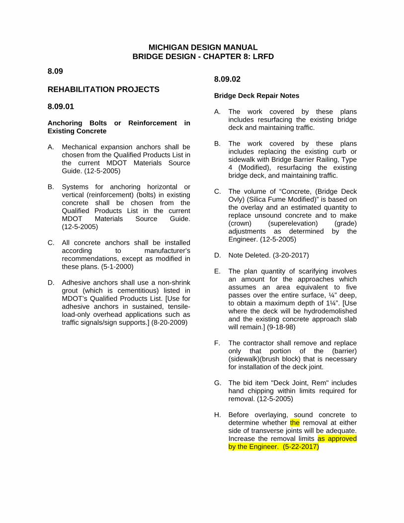
MICHIGAN DESIGN MANUAL BRIDGE DESIGN - CHAPTER 8: LRFD
8.09 REHABILITATION PROJECTS 8.09.01 Anchoring Bolts or Reinforcement in Existing Concrete A. Mechanical expansion anchors shall be
chosen from the Qualified Products List in the current MDOT Materials Source Guide. (12-5-2005)
B. Systems for anchoring horizontal or
vertical (reinforcement) (bolts) in existing concrete shall be chosen from the Qualified Products List in the current MDOT Materials Source Guide. (12-5-2005)
C. All concrete anchors shall be installed
according to manufacturer’s recommendations, except as modified in these plans. (5-1-2000)
D. Adhesive anchors shall use a non-shrink
grout (which is cementitious) listed in MDOT’s Qualified Products List. [Use for adhesive anchors in sustained, tensile-load-only overhead applications such as traffic signals/sign supports.] (8-20-2009)
8.09.02 Bridge Deck Repair Notes A. The work covered by these plans
includes resurfacing the existing bridge deck and maintaining traffic.
B. The work covered by these plans
includes replacing the existing curb or sidewalk with Bridge Barrier Railing, Type 4 (Modified), resurfacing the existing bridge deck, and maintaining traffic.
C. The volume of “Concrete, (Bridge Deck
Ovly) (Silica Fume Modified)” is based on the overlay and an estimated quantity to replace unsound concrete and to make (crown) (superelevation) (grade) adjustments as determined by the Engineer. (12-5-2005)
D. Note Deleted. (3-20-2017) E. The plan quantity of scarifying involves
an amount for the approaches which assumes an area equivalent to five passes over the entire surface, ¼” deep, to obtain a maximum depth of 1¼”. [Use where the deck will be hydrodemolished and the existing concrete approach slab will remain.] (9-18-98)
F. The contractor shall remove and replace
only that portion of the (barrier) (sidewalk)(brush block) that is necessary for installation of the deck joint.
G. The bid item "Deck Joint, Rem" includes
hand chipping within limits required for removal. (12-5-2005)
H. Before overlaying, sound concrete to
determine whether the removal at either side of transverse joints will be adequate. Increase the removal limits as approved by the Engineer. (5-22-2017)