Embed Size (px)
Citation preview

AD
(P
'D ^
MAR U 068
Reproduced by the CLEARINGHOUSE
(or Federal Scientific & Technical Information Springfield Va 22151
tertow^Massochusetts 021 %

AMMRC TR 68-02
THE FINE MICROSTRUCTURE OF PYROLYTIC GRAPHITE AS INFLUENCED BY BORON
Technical Report by
R.NATHAN KATZ AND CHARLES P. GAZZARA
January 1%8
This document has been approved for public release and sale; its distribution is unlimited.
D/A Project 1C024401A330 AMCMS Code 5025.11.29600
Ceramic Materials Research for Army Materiel Subtask 35512
ARMY MATERIALS AND MECHANICS RESEARCH CENTER WATERTOWN. MASSACHUSETTS 02172

ARMY MATERIALS AND MECHANICS RESEARCH CENTER
THE FINE MICROSTRUCTURE OF PYROLYTIC GRAPHITE AS INFLUENCED BY BORON
ABSTRACT
A study of the fine rnicrostructure of boronated pyrolytic graphite was made utilizing optical and X-ray diffraction techniques. The influence of boron content on the laminar structure, the lattice parameter, the lattice strain, the particle size, and the flexural strength of pyrolytic graphite were studied. Significant changes in the behavior of all investigated parameters were observed in the 0.50 to 0.75 percent boron range. A mechan- ism relating these changes to the appearance of B^C deposit is hypothesized.

CONTENTS
Paqe
ABSTRACT
INTRODUCTION 1
MATERIALS AND TEST PROCEDURES 1
RESULTS 3
Mechanical Properties 3
X-Ray Diffraction Analysis 4
Discussion of Results 8
SUMMARY 10
APPENDIX A 11
APPENDIX B 12
LITERATURE CITED 14

INTRODUCTION
It has been known that the nature of the growth cone structure of pyro- lytic graphite bears a strong relationship to the mechanical properties.*»2
It is conceivable, however, that other microstructural features of a finer nature may also exert some influence on these properties. For example, there are some indirect indications in the work of Kotlensky3 and Kotlensky and Martens'* that the X-ray crystallite size nay relate to the tensile strength of pyrolytic graphite. Tarpinian5 has suggested that the laminar structure of pyrolytic graphite, as revealed by cathodic Hg ion bombardment, may be related to the X-ray crystallite size. It is not unreasonable to assume that the size and spacing of such laminar features may influence the mechanical properties of the material.
This finer scale microstructure is investigated here. The influence of boron content will be shown on the following parameters: growth cone structure; the laminar features which are revealed by Hg ion bombardment etching; the magnitude of X-ray strain broadening; the lattice parameter in the "cM direction; and the X-ray crystallite size. In addition, an attempt will be made to correlate the above phenomena with the flexural strength observed on these materials. An hypothesis which rationalizes the observed behavior will be presented.
MATERIALS AND TEST PROCEDURES
The pyrolytic graphite used in this investigation was obtained from the Raytheon Company, Waltham, Massachusetts. Five plates of boronated pyrolytic graphite were deposited at 1850 C. The boron contents (in weight percent) of four of the plates were 0.25, 0.50, 0.75, and 1 percent. The fifth plate had a nearly linear compositional gradient along one direction ranging from approximately 1.2 to 3.3% B. One plate of pyrolytic graphite, deposited under the same conditions with 0% B, was obtained as a control. For mechanical tests bend specimens of dimensions 2-1/2" by 3/8" by 1/4" were cut from each plate, the 1/4" dimension correspondinj» to the "c" or growth direction. The specimens from the first four plates had compositions which were 0.25, 0.50, 0.75, and 1% boron respectively throughout the bar. The bars taken from the fifth plate were cut so that they gave compositions of approximately 1.3, 2.3, and 3.3% in the middle of the 2-1/2" length of the bar. This insured that each bar cut from the fifth plate had the same boron content in the portion of the bar which bore the maximum load during a four-point loading flexural test. Therefore, the flexural strengths obtained were representative of the compositions quoted. One can have confidence that the effects noted on the 1.3, 2.3, and 3.3% boron specimens are due to increasing boron content even though the actual boron content may have differed by as much as 0.25%. (These specimens which are nominally 1,3%, nominally 2.3%, and nominally 3.3% boron will be referred to as 1.3?6, 2.3%, and 3.3% throughout the report). The density of all of the materials, within the sensitivity of the measurements, was 2.21 to 2.22 g/cc or 98.5* of the theoretical.
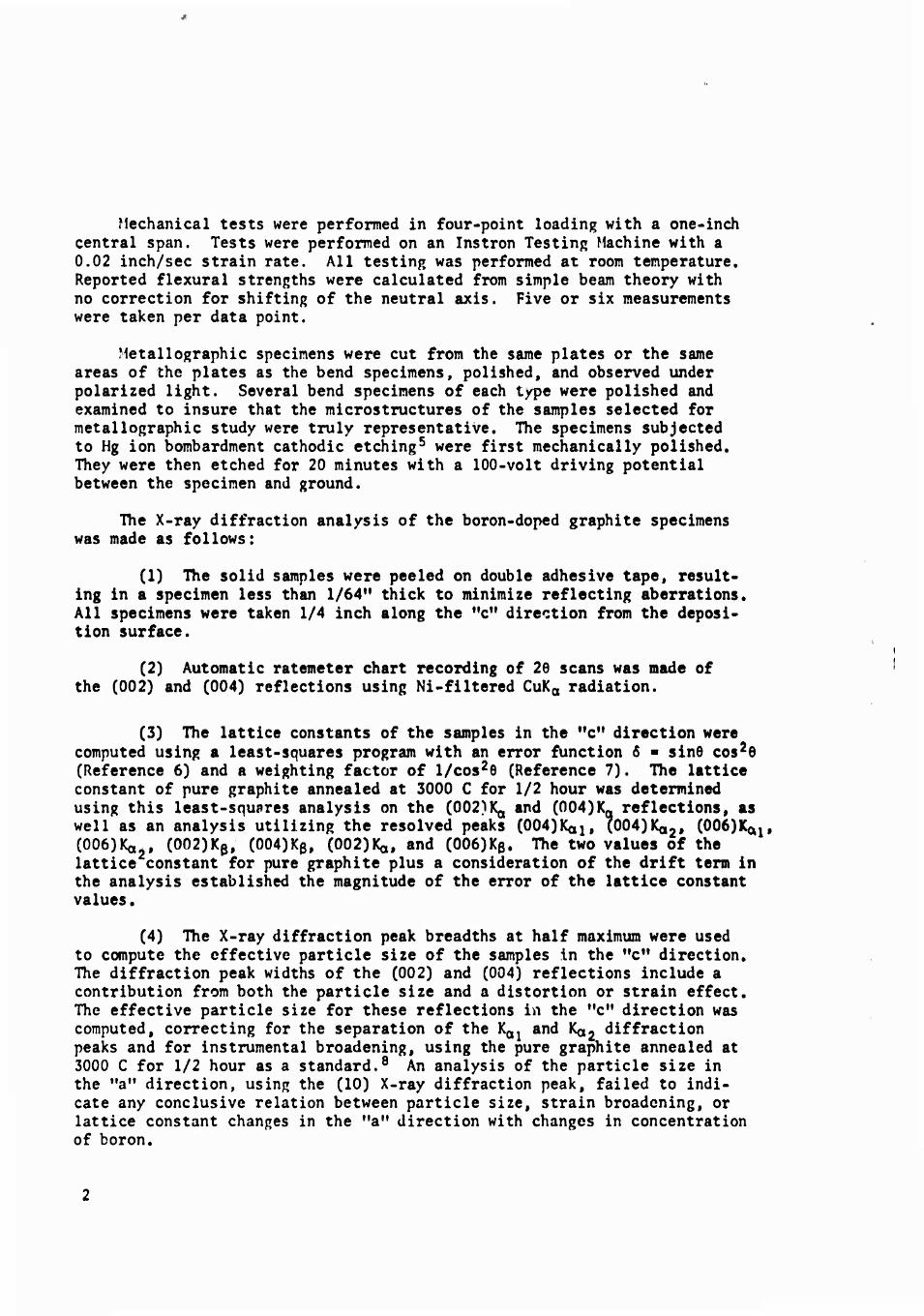
Mechanical tests were performed in four-point loading with a one-inch central span. Tests were performed on an Instron Testing Machine with a 0.02 inch/sec strain rate. All testing was performed at room temperature. Reported flexural strengths were calculated from simple beam theory with no correction for shifting of the neutral axis. Five or six measurements were taken per data point.
Metallographic specimens were cut from the same plates or the same areas of the plates as the bend specimens, polished, and observed under polarized light. Several bend specimens of each type were polished and examined to insure that the microstructures of the samples selected for metallographic study were truly representative. The specimens subjected to Hg ion bombardment cathodic etching5 were first mechanically polished. They were then etched for 20 minutes with a 100-volt driving potential between the specimen and ground.
The X-ray diffraction analysis of the boron-doped graphite specimens was made as follows:
(1) The solid samples were peeled on double adhesive tape, result- ing in a specimen less than 1/64" thick to minimize reflecting aberrations. All specimens were taken 1/4 inch along the "c" direction from the deposi- tion surface.
(2) Automatic ratemeter chart recording of 26 scans was made of the (002) and (004) reflections using Ni-filtered CuKa radiation.
(3) The lattice constants of the samples in the "c** direction were computed using a least-squares program with an error function 6 ■ sine cos26 (Reference 6) and a weighting factor of l/cos2e (Reference 7). The lattice constant of pure graphite annealed at 3000 C for 1/2 hour was determined using this least-squares analysis on the (002)Ka and (004)1^ reflections, as well as an analysis utilizing the resolved peaks (004)1^!, (004)Ka«, (006)Kap (006)1^ , (002)Kß, (004)Kß, (002)1(0, and (006)Kß. The two values of the lattice constant for pure graphite plus a consideration of the drift term in the analysis established the magnitude of the error of the lattice constant values.
(4) The X-ray diffraction peak breadths at half maximum were used to compute the effective particle size of the samples in the "c" direction. The diffraction peak widths of the (002) and (004) reflections include a contribution from both the particle size and a distortion or strain effect. The effective particle size for these reflections in the "c" direction was computed, correcting for the separation of the K01 and Koj diffraction peaks and for instrumental broadening, using the pure graphite annealed at 3000 C for 1/2 hour as a standard.8 An analysis of the particle size in the "a" direction, using the (10) X-ray diffraction peak, failed to indi- cate any conclusive relation between particle size, strain broadening, or lattice constant changes in the "a" direction with changes in concentration of boron.

RESULTS
Mechanical Properties
Figure 1 shows the flexural strength of boron-doped pyrolytic graphite as a function of boron content. It will be noted that in going from 0 to 0.50% B the strength falls off; from 0.75 to 1.3% B, it increases rapidly with boron content; to 2.3% B, it increases gradually; and at 3.3% B, it falls slightly. The uniformity of composition among specimens in the 1.3 to 2.3% B range was shown by the small amount of scatter encountered.
Optical Metallonraphy
The structures observed in mechanically polished specimens viewed in polarized light at 100X showed that all the material was singularly nucle- ated coarse cone material. This technique revealed no difference in microstrueture with boron content. A typical microstrueturc is presented in Figure 2. By contrast, the laminar structure produced by mercury ion bombardment revealed that considerable differences occur with increasing boron content of the samples.
25 L T
♦ ♦
Specimens tested in above orientation
t "c" Direction
_L
0.5 1 1.5 2.0 2.5
Percent Boron
3.0 3.5
Figure 1. FLEXURAL STRENGTH OF BORONATED PYROLYTIC GRAPHITE VERSUS BORON CONTENT IN WEIGHT PERCENT
Figure 2. SINGULARLY NUCLEATED COARSE CONE STRUCTURE BORONATED PYROLYTIC GRAPHITE Typical Microstructure 0 to 3.3% B. Mag. 100X, Polarized Light.
19-066-i47VAM( -67

Figures 3a, 3b, and 3c show the nature of the laminar features which were present in the 0, 0.25, and 0.50% B samples. The size of the laminar features that were present in compositions between 0 and 0.75% B were essentially the same. At 0.50% B these laminar features were approximately 20 to 60u long and 2 to 3u thick, and they were continuous across the pri- mary cone boundary. When the boron content changed to 1%, the laminar features decreased in length very markedly to about 10 to 20y and did not exceed 2\i in width. These lamellar features also lost, to a large degree, their continuity across the primary cone boundary as shown in Figure 3d, At a nominal 1.3% boron, the laminar features were further reduced in size to ti.9 5 to 15u range and were only ly thick. Again there was a general lack of continuity across the boundary (Figure 3e). As the boron content is increased further to 2.3%, the trend evident above continued (Figure 3f). However, when the boron content reached the level of 3.3%, extremely long, thick laminar features appeared throughout the structure. These features were longer and thicker than those in the 0.50% B material and they were less closely spaced, as shown in Figure 3g. Such features were also evi- dent in one portion of a 2.3% boron sample. In this particular sample, they were associated with a band, similar to banding in alloy steels, which ran across the entire specimen. However, this banding was not a general feature in the 2.3% B sample, whereas the heavy laminar features were quite general in the 3.3% B sample.
X-Ray Diffraction Analysis
The variation of the lattice constants in the "c" direction of the boron-doped pyrolytic graphite is presented in Figure 4. This variation in lattice parameter is consistent with the effects of boron content on the graphitization of boronated pyrolytic graphites measured by Kotlensky* although the region increase in "c" spacing is shifted to lower boron additions.
The procedure of Williamson and Hall9 for computing the root-mean- squared strain in the "c" direction, (n2)1/2, was followed, assuming large strain values having a Gaussian strain distribution.
The values for (n2)1/2 were calculated from the expression:
^2)1/2 . ßcose(ao) /27(0.89)U
d**^7 /JiT
where ß = corrected peak breadth 6 = Bragg angle
a0 = lattice constant I ■ Miller index X ■ wave length
0.89 « shape constant (Ref. 10) e ■ slope of ß* versus d* curve for (002) and (004) peakst
fThe absolute particle size is taken from this curve as Vß* at d* • 0,

T ^>^~ * • m i mim ii
11 • . us--^. ;««»iiS!BafiSLL_i-H
a. 0% B
e. 0.5% B u (i h.
-5
II
b. 0.25% B
Figur« 3. LAMINAR STRUCTURE OF BORONATED PYROLYTIC GRAPHITE REVEALED BY Hg ION BOMBARDMENT ETCH. Mag 500X, Polarized Light
19-066-l476'AM( «1
g. 3.3% B

o^
T O
.X-
I o
1
T •O"
1
Percent Boron
Figure 4. LATTICE PARAMETER IN THE "c" DIRECTION VERSUS WEIGHT PERCENT BORON
Applying the equation to the (002) and (004) X-ray diffraction peaks, the maximum value of (n2)1'2 computed for the boronated samples is 0.0072 and the minimum value is 0.0046. The maxiumum value of (n2)1/2 is not as high as that reported for thoria, 0.10, (obtained using a similar analysis pro- cedure)11 but is considerably higher than those obtained for metals, i.e. (n2)1/2 « 0.001 for Al and w'.9
Figures 5 and 6 show the results of refined calculations yielding the variation with boron content of strain and particle size (in absolute, not normalized, units) in the "c" direction. Figure 6 shows that the absolute particle size maximizes for specimens containing approximately 0.75% B and then slowly decreases to a level considerably above the pure graphite par- ticle size value. The particle size for 0.50% B is given as two values outside the limits of error of the X-ray diffraction results. This is probably due to a difference in the boron content of these two specimens in the region of steepest ascent of the curve.

0.009
0.008 -
CM
0.007 o
0.006
0.005
0.004
Percent Boron
Figures. LATTICE STRAIN VERSUS WEIGHT PERCENT BORON
Percent Boron
Figure 6. X-RAY CRYSTALLITE SIZE IN "c" DIRECTION VERSUS WEIGHT PERCENT BORON

The error bars shown in Figures 5 and 6 were calculated on the basis of a 5% experinental error limit in the peak width of the (002) and the (004) reflections. It should be emphasized that the absolute values of particle size and strain are correct to the extent of the validity of the assumptions made, namely, the shape constant, the size, and the distribution functions of crystallite size and strain. The curves are unchanged, however, regard- less of the assumptions made, since no changes in the curves could be observed in changing from normalized to absolute units.
Discussion of Results
The results presented in the preceding section have indicated that the boron content exerts a large influence on the laminar features, the X-ray strain broadening, the crystallite size, and the flexural strength, A coin- cidence of inflections in Figures 1, 4, 5, and 6, is also apparent. Clearly some major change is occurring in this material as the composition changes from the 0.25 to 0.50% B region to the 0.75 to 1% B region. Smaller effects are also occurring at other compositions. To briefly summarize, some of the effects noted are listed.
1. On introducing boron into the graphite lattice, the flexural strength apparently rises slightly, then at 0.5% B falls to a minimum after which it rapidly increases above the strength level attained with 0% B. At 3.3% B the strength again falls off slightly.
2. Upon crossing the region between 0.5% and 1% B there is a large diminution of laminar features (until a banding phenomenon becomes present at 3,3% B),
3. The "c" lattice spacing undergoes a decrease (that is, graph- itization is enhanced) on adding boron up to 0.5%. Additions of boron beyond this amount results in an increased "c" spacing.
4. A large amount of lattice strain appears at approximately 1% boron.
The problem of finding a mechanism or rationale to explain the simul- taneous occurrence of these seemingly diverse phenomena now presents itself,
Arai and Kanter12 have observed that boron in graphite up to 4000 ppm is essentially in solid solution, although at 4000 ppm some may be present as I^C, Lowell13 has recently determined the boron-Bj^C solvus line on the boron-carbon phase diagram. He found that the maximum solubility of boron in natural graphite at 1850 C is approximately 1%, and that substitutional boron in the graphite decreased the lattice parameter.
Kotlensky,11* for boronated pyrolytic graphite deposited at 2000 C, has also noted a reduction of lattice spacing with substitutional boron up to approximately 1%, after which the lattice parameter starts to increase, but within the compositions studied did not regain its original value. He attributes the increase to the presence of interstitial boron,
8

This interstitial boron is most likely present as B^C, based on the findings of Arai and Kanter12 and Lowell.13 Thus, the variation in "c" spacing with boron content shown in Figure 4 is essentially in agreement with the findings of Kotlensky, namely that the substitutionally added boron (up to O.S% B) enhances graphitization (that is, decreases the "c" spacing) and interstitial boron present as Bj+C increases "c" spacing. Due to the difference in deposi- tion conditions and the nature of the graphites involved, one cannot be exact in stating the solubility limit of boron in the graphite tested in this investigation based on the above solubility studies. However, on the basis of all available evidence, the solubility limit must be between 0.4% and 1% - the very region in which large changes of behavior were observed in the investigated parameters. It therefore seems likely that the results listed above are related to the appearance of B^C,
The presence of B»^ can be used to explain both the appearance and dis- appearance of microstrains in the lattice and the transitions noted above in the laminar features revealed by Mg ion etching. If the B^C deposits pyrolytically with the carbon, it is possible that small regions of B^C will form a coherent interface with the graphite lattice. Coherent interfaces are known to produce severe volume microstrains in the matrix.15 As the boron concentration increases, it is likely that the size of B^C deposits increases. If this were the case, eventually they would "lose" coherency and become a second phase with a noncoherent boundary. Such a loss in coherency should be observable by a relief of the microstrains that were present because of the coherent boundary. On increasing boron content beyond 0%, X-ray strain broadening behavior indicates only small strains present at 0.50% B, severe strains present at 1 and 1.3% B, and small strains again at compositions of 2.3 and 3.3% B, This can be understood in terms of no or very little BjjC deposits present at 0.5% B, coherent deposits of B^C present at 1 and 1.3% B, and noncoherent deposits of B^C present at 2.3% and 3.3% B.
The presence of B^C deposits also provides a rationale for the behavior of the laminar structure of the boronated pyrolytic graphite with increasing boron content. To understand this effect, no claim need be made for the exact nature of the microfeatures, other than to state tha they are truly boundaries between regions in the graphite and not microcracks. That these features are not microcracks has been substantiated by ekitron Microscopy5
and studies of cracks in the material*. Although the features are not themselves cracks, there are often microcracks associated with the features as shown in the electron micrograph in Figure 7 (see also Appendix A). The laminar features are most probably plate-shaped which was determined from the fact that their appearance is not altered by changing the angle of the observed surface with regard to the "a11 axis, and that these features are observed only on the surface parallel and not perpendicular to the "c" axis. The features are present in the as-deposited material and so must be a result of the deposition process. Also, these features are present in mate- rial with 0% B and hence are not second phase. If Bi,C is depositing with
*Katz, R, N,t and Aaouaviva, S, F. Amy Materials and Mechanics Fesearch Centert unpublished data.

.Cracksv the pyrolytic graphite, it is possible that the B^C deposits will limit the extent of the laminar features, i.e., the greater the amount of Bi+C dispersed the greater the restriction on the extent of the laminar features. This behavior is observed in the composition range 0.50% to 2.3% B. The banding effect in the 3.3% material may result from favored areas of deposition for Bi^C, but the authors have no substan- tive evidence to validate this.
The microscopic and X-ray evidence which indicates a Bi^C deposit but does not conclusively prove it (see Appendix B) is analogous to a coherent-noncoher-
. ent precipitation phenomenon typically tf ff / / encountered in age-hardened metals.
On this basis, the improved flexural strengths obtained in going from 0.50% to 2.3% B and the slight drop in strength at 3.3% B can be understood. It is in- teresting to note that the presence of boron in excess of 0.50% inhibits the shear mode of failure. Most specimens
of these compositions did not fracture but rather lost their ability to carry a load. This resulted from the generation of one or more dclaminations per- pendicular to the "c" axis of the specimen. The slight increase in the strength of the 0.25% B specimens with regard to the 0% specimens is probably a conse- quence of the lower magnitude of lattice strains in these specimens.
Figur« 7. MICROCRACKS ASSOCIATED WITH LAMINAR FEATURES IN 0.5% BORON PYROLYTIC
GRAPHITE. Mag. 7000X, Cr-Shodowed Replica. 19-066-1477/AMC-67
SUMMARY
The authors have presented some of the effects of boron on the fine microstructure of pyrolytic graphite. The relationship of these features to the flexural strength of boronated pyrolytic graphite has shown that these fine microfeatures and not the usually examined growth cone structure cor- relate with the observed properties. A coherent-noncoherent Bi^C deposition mechanism to explain the observed results was advanced. It is hoped that more work relating the fine microstructure of pyrolytic graphite and other layered materials will ensue.
10

APPENDIX A. ELECTRON MICROGRAPHIC EVIDENCE OF THE NATURE OF THE LAMINAR FEATURES
In the main body cf the report it was stated that the laminar features were not cracks and various evidence was cited to support the contention. An additional piece of direct evidence is presented here. Figure A-l, an electron micrograph of a scratch on the Hg ion etched surface of 0.5% B sample, shows that the laminar features have been deflected by a scratch. An enlarged view of such a deflected feature is also shown. If the lamimar features were not true structural features but were cracks, one would expect that they should be filled in rather than deflected as shown by these micrographs.
'* ^»J^jW^^n 5 •■ ^
r
*'*«-i<t >- ■ . H ■ *■ ■■A..' ' *
' l ■ '
■ [
7,000X 54,000 X Figure A-l. SCRATCH DEFLECTING LAMINAR FEATURES IN 0.5% BORON PYROLYTIC GRAPHITE SAMPLE
19-066-1479/AMC:-67 19-066-1480/AMC-67
11

APPENDIX B. ELECTRON DIFFRACTION ANALYSIS OF SECOND-PHASE PARTICLES EXTRACTED FROM A 2.3% BORON SAMPLE
While examining Cr-shadowed replicas of the Hg ion bombarded surfaces of boronated pyrolytic graphite under the electron microscope (see Figure 7), several "pulled-out" particles of a second phase were encountered. These particles were principally located at the interface between the laminar features and the matrix and were first observed at the 2.3% B level. One of the particles studied is delineated by the arrow in Figure B-l; this par- ticle is situated on the boundary of a large laminar feature and the matrix. The significance of observing a second phase at the 2.3% B level is that if the coherent-noncoherent B^C deposit hypothesis advanced in the report is correct, one would not expect to observe a second phase (by other than X-ray diffraction techniques) until the second phase becomes noncoherent and this noncoherence would be predicted to occur between 1.3 and 2.3% B. Electron diffraction patterns of these particles were taken. An analysis of the spots in these patterns (Figure B-2) revealed that after eliminating the spots which could have been caused by the Cr shadowing and graphite matrix, the patterns could have been produced by either rhombohedral boron16 or Bi,C (Reference 17).
Although the electron diffraction data cannot distinguish whether boron or BttC is the second phase, a strong thermodynamic argument may be made for Bi^C, since it has a negative free energy of formation at the deposition temperature.18 Regardless of the exact second phase involved, its appearance at the composition predicted provides strong support for the advanced hypothesis
The authors would like to express their thanks to M. Dumais for his help with this portion of the work.
Figur« B-l. ELECTRON MICROGRAPH OF 2.3% BORON PYROLYTIC GRAPHITE SAMPLE SHOWING SECOND PHASE PULL OUT USED FOR ELECTRON DIFFRACTION STUDY
19-066-1481/AM C-67 Ma«. 21,000X
12

Figure 6-2. ELECTRON DIFFRACTION PATTERN OBTAINED FROM SECOND PHASE PARTICLE.
19-06 6-1478/AM C-67
13

LITERATURE CITED
1. DONADIO, R. N., and PAPPIS, J. The Mechanical Properties of Pyrolytic Graphite, Raytheon Tech. Memo T-574, 1964.
2. GEBMART, J. J., and BERRY, J. M, Mechanical Properties of Pyrolitic Graphite, AIAA Journal, v, 3 (2), 1965, p. 302-308.
3. KOTLENSKY, W. V., and MARTENS, H, E. Structural Changee Accompanying Deformation in Pyrolitic Graphite. Journal of American Ceramics Society, March 1965, p. 135,
4. KOTLENSKY, W. V., and MARTENS, H. E. Mechanical Propertiee of Pyrolitic Graphite to 2800 C, Proceedings 5th Carbon Conference, Pergamon Press, v. 1, p. 631.
5. TARPINIAN, A. The Metallography of Pyrolytic Graphite, Army Materials and Mechanics Research Center, Watertown, Massachusetts, AMRA TR 64-41, December 1964; also Electrochemical and Ion Bombardment Etching of Pyrolitic Graphite, Journal of American Ceramics Society, v. 47 (10), 1964.
6. KLUG, H. P., and ALEXANDER, L. E. X~Ray Diffraction Proceduree, J. Wiley and Sons, New York, 1954.
7. HESS, J. B. A Modification of the Cohen Procedure for Computing Precision Lattice Constants from Powder Data, Acta Cryst., v. 4, 1951, p. 209.
8. RAU, R. C. Measurement of Crystallite Size by Means of X-Ray Diffraction Line-Broadening, Norelco Reporter, v. 10, no. 3, 1963, p. 114.
9. WILLIAMSON, G. K., and HALL, W. H. X~Ray Line Broadening from Filed Aluminum and Wolfram, Acta Met,, v. 1, 1953, p. 22.
10. RANDAL, J. T., ROOKSBY, H. P., and COOPER, B. S. X-Ray Diffraction and the Structure of Vitreous Solids - I, Z, Krist., v. 75, 1930, p. 196,
11. LEWIS, D., and LINDLEY, M. W. Strain Induced Activity in Thoria and Its Relief With Temperature, Journal of Nuclear Mat., v. 17, 1965, p. 347.
12. ARAI, G, J., and KANTER, M. A. On the Lattice Parameters of Graphite Containing Boron as an Impurity, Abstract No. 158, Carbon V., v. 2, 1964.
13. LOWELL, C. E. Solid Solution of Boron in Graphite, Journal of American Ceramics Society, v. 50 (3), 1967, p, 142.
14. KOTLENSKY, W. V. The Effect of Boron on the Level of Graphitization of BPG, Carbon, v. 5 (4), 1967, p. 109,
15. BARRETT, C, and MASSALSKI, T, B, Structure of Metals, 3rd Edition, McGraw-Hill Book Company, Inc., 1966.
16. ASTM, X-Ray Diffraction Data Cards, Card No, 12-377,
17. ASTW, X-Ray Diffraction Data Cards, Card No. 6-0555.
18. WICKS, C. E., and BLOCK, F. E. Thermodynmic Properties of 65 Elements ~ Their Oxides, Carbides, and nitrides. Bureau of Mines Bulletin 605, 1963.
14

UNCLASSIFIED Security Claisification
DOCUMENT CONTROL DATA • R&D (Saeurily claatUlcmHon ol Utlm, body ol abatrmel and InduHing annotation muat be ontarad whan lha ovarall rapott ia claaalllad)
I ORICINATINO ACTIVITY (Cotpormta author)
Army Materials and Mechanics Research Center Watertown, Massachusetts 02172
2a NCPOMT SECURITY CLASSIFICATION
Unclassified 2 6 GROUP
3 RfPOUT TITLE
THE FINE MICROSTRUCTURE OF PYROLYTIC GRAPHITE AS INFLUENCED BY BORON
4 DESCRIPTIVE NOTES (Typa ol rapott and Incluaiva data»)
S AUTHORfSJ (Laat name, lint name. Initial)
Katz, R. Nathan, and Cazzara, Charles P.
6. REPORT DATE
January 1968 7« TOTAL NO OF PACF?
11 76. NO OF REFS
1L ta. CONTRACT OR 6RANT NO.
b. PROJECT NO. D/A1C024401A330
c AMCMS Code 5025.11.29600
d. Subtask 35512
9a ORIGINATOR'S REPORT NUMBERfS;
AMMRC TR 68-02
9b OTHER REPORT NOCSJ Mny ofhar numbara that may ba atalfiad thii raport)
tO AVAILABILITY/LIMITATION NOTICES
This document has been approved for public release and sale; its distribution is unlimited.
II SUPPLEMENTARY NOTES 12 SPONSORING MILITARY ACTIVITY
U. S, Army Materiel Command Washington, D. C. 20315
13 ABSTRACT A study of the fine microstructure of boronated pyrolytic graphite was
made utilizing optical and X-ray diffraction techniques. The influence of boron content on the laminar structure, the lattice parameter, the lattice strain, the particle size, and the flexural strength of pyrolytic graphite were studied. Significant changes in the behavior of all investigated parameters were observed in the 0.50 to 0.75 percent boron range. A mechanism relating these changes to the appearance of B^C deposit is hypothesized. (Authors)
DD Mi'.. 1473 UNCLASSIFIED
Security Classification

UNCLASSIFIEÜ Security Classification
14 KEY WORDS
Pyrolytic graphite Microstructure X-ray analysis Mechanical properties Boron doping Ion-Bombardment etching Lattice strains Alloying
.INK A
ROLE »VT
LINK B
ROLE WT
LINK C
ROLE
INSTRUCTIONS
1. ORIGINATING ACTIVITY: Enter the name and address of the contractor, subcontractor, grantee. Department of De- fense activity or other organization (corporate author) issuing the report.
2a. REPORT SECUHTY CLASSIFICATION: Enter the over- alt security classification of the report. Indicate whether "Restricted Data" is included. Marking is to be in accord- ance with appropriate security regulations.
2b. GROUP: Automatic downgrading is specified in DoD Di- rective 5200.10 and Armed Forces Industrial Manual. Enter the group number. Also, when applicable, show that optional markings have been used for Group 3 and Group 4 as author- ized.
3. REPORT TITLE: Enter the complete report title in all capital letters. Titles in all cases should be unclassified. If a meaningful title cannot be selected without classifica- tion, show title classification in all capitals in parenthesis immediately following the title.
4. DESCRIPTIVE NOTE:<- If appropriate, enter the type of report, e.g., interim, progress, summary, annual, or final. Give the inclusive dates when a specific reporting period is covered.
5. AUTHOR(S): Enter the name(s) of authoKa) as shown on or in the report. Enter last name, first name, middle initial. If military, show rank and branch of service. The name of the principal author is an absolute minimum requirement.
6. REPORT DATE: Enter the date of the report a* day, month, year; or month, year. If more than one date appears on the report, use date of publication.
7a. TOTAL NUMBER OF PAGES: The total page count should follow normal pagination procedures, i.e., enter the number of pages containing information.
76. NUMBER OF REFERENCES: Enter the total number of references cited in the report.
8a. CONTRACT OR GRANT NUMBER: If appropriate, enter the applicable number of the contract or grant under which the report was written.
86, 8c, & bd. PROJECT NUMBER: Enter the appropriate military department identification, such as project number, subproject number, system numbers, task number, etc.
9«. ORIGINATOR'S REPORT NUMBER(S): Enter the offi- cial report number by which the document will be identified and controlled by the originating activity. This number must be unique to this report.
96. OTHER REPORT NUMBER(S): If the report has been assigned any other report numbers (either by the originator or by the sponsor), also enter this numberf s).
10. AVAILABILITY/LIMITATION NOTICES: Enter any lim- itations on further dissemination of the report, other than those imposed by security classification, using standard statements such as:
(1) "Qualified requesters may obtain copies of this report from DDC"
(2) "Foreign announcement and dissemination of this report by DDC is not authorized."
(3) "U. S. Government agencies may obtain copies of this report directly from DDC. Other qualified DDC users shall request through
it
(4) "U. S. military agencies may obtain copies of this report directly from DDC Other qualified users shall request through
(S) "All distribution of this report is controlled. Qual- ified DDC users shall request through
If the report has been furnished to the Office of Technical Services, Department of Commerce, for sale to the public, indi cate this fact and enter the price, if known.
11. SUPPLEMENTARY NOTES; Use for additional explana- tory notes.
12. SPONSORING MILITARY ACTIVITY: Enier the name of the departmental project office or laboratory sponsoring (pay- ing tor) the research and development. Include address. 13. ABSTRACT: Enter an abstract giving a brief and factual summary of the document indicative of the report, even though it may also appear elsewhere in the body of the technical re- port. If additional space is required, a continuation sheet shall be attached.
It is highly desirable that the abstract of classified re- ports be unclassified. Each paragraph of the abstract shall end with an indication of the military security classification of the information in the paragraph, represented as (TS), <S), (C). or (V).
There is no limitation on the length of fb<» abstract. How- ever, the suggested length is from 150 to 225 words.
14. KEY WORDS: Key words are technically meaningful terms or short phrases that characterize a report and may be used as index entries for cataloging the report. Key words must be selected so that no security classification is required. Iden- fiers, such as equipment model designation, trade name, "nlli- fary project code name, geographic location, may be used as key words but will be followed bv an indication of technical context. The assignment of links, rules, and weights is optional.
UNCLASSIFIED Security Classification