Embed Size (px)
Citation preview

Digital process transmitter for monitoring andvisualizing analog measured values
Application
• Plant and apparatus engineering and construction• Control rooms and cabinets• Laboratories• Process recording and supervision• Process control• Signal adjustment and signal conversion• WHG compliant limit signal transmitter
Your benefits
• 5-digit, 7-segment backlit LC display• User-configurable dot matrix display range for bar graph, units and tag name• 1 or 2 universal inputs• 2 relays (optional)• Min./max. value saved• 1 or 2 calculated values• One linearization table with 32 points for each calculated value• 1 or 2 analog outputs• Digital status output (open collector)• Operation using 3 keys• Configuration via interface and FieldCare or DeviceCare software
Products Solutions Services
Technical InformationRMA42Process transmitter with control unit
TI00150R/09/EN/05.1671315973

RMA42
2 Endress+Hauser
Function and system design
Measuring principle
Analog in 1
Analog in 2
A0011762
1 Example for "differential pressure" application
The RMA42 process transmitter powers the transmitter and processes analog signals fromtransmitters, particularly from the area of process instrumentation. These signals are monitored,evaluated, calculated, saved, separated, linked, converted and displayed. The signals, intermediatevalues and the results of calculations and analysis are transmitted by digital or analog means.
Measuring system The RMA42 is a process transmitter, which is controlled by a microcontroller, and exhibits a display,analog inputs for process and status signals, analog and digital outputs, as well as an interface forconfiguration.
Connected sensors (e.g. temperature, pressure) can be powered by the integrated transmitter powersupply system. The signals to be measured are converted from analog to digital signals, processeddigitally in the device, and then converted from digital to analog signals and made available to thevarious outputs. All measured values, and values calculated in any way, are available as a signalsource for the display, all outputs, relays and the interface. It is possible to make multiple use of thesignals and results (e.g. a signal source as an analog output signal and limit value for a relay).
Mathematics functions The following mathematics functions are available in RMA42:• Sum• Difference• Multiplication• Mean• Linearization
Linearization function
Up to 32 user-definable points are available in the device per calculated value to linearize the input,e.g. for tank linearization. In the case of the two-channel device (option), mathematics channel M2can be used to linearize mathematics channel M1.
Linearization is also available in the FieldCare configuration software.
RMA42
Endress+Hauser 3
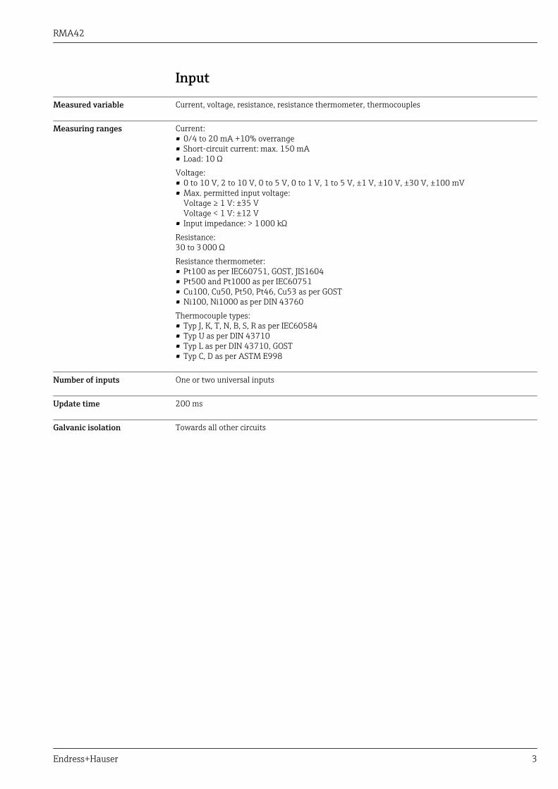
Input
Measured variable Current, voltage, resistance, resistance thermometer, thermocouples
Measuring ranges Current:• 0/4 to 20 mA +10% overrange• Short-circuit current: max. 150 mA• Load: 10 ΩVoltage:• 0 to 10 V, 2 to 10 V, 0 to 5 V, 0 to 1 V, 1 to 5 V, ±1 V, ±10 V, ±30 V, ±100 mV• Max. permitted input voltage:
Voltage ≥ 1 V: ±35 VVoltage < 1 V: ±12 V
• Input impedance: > 1 000 kΩResistance:30 to 3 000 ΩResistance thermometer:• Pt100 as per IEC60751, GOST, JIS1604• Pt500 and Pt1000 as per IEC60751• Cu100, Cu50, Pt50, Pt46, Cu53 as per GOST• Ni100, Ni1000 as per DIN 43760Thermocouple types:• Typ J, K, T, N, B, S, R as per IEC60584• Typ U as per DIN 43710• Typ L as per DIN 43710, GOST• Typ C, D as per ASTM E998
Number of inputs One or two universal inputs
Update time 200 ms
Galvanic isolation Towards all other circuits

RMA42
4 Endress+Hauser
Output
Output signal One or two analog outputs, galvanically isolated
Current/voltage output
Current output:• 0/4 to 20 mA• Overrange up to 22 mAVoltage:• 0 to 10 V, 2 to 10 V, 0 to 5 V, 1 to 5 V• Overrange: up to 11 V, short-circuit proof, Imax < 25 mA
HART®
HART® signals are not affected
Loop power supply • Open-circuit voltage: 24 VDC (+15% /-5%)Ex version: > 14 V at 22 mANon-hazardous operation: > 16 V at 22 mA
• Maximum 30 mA short-circuit-proof and overload-proof• Galvanically isolated from system and outputs
Switching output Open Collector for monitoring of the device state and alarm notification. The OC output is closed innormal state. In error state, the OC output is opened.
• Imax = 200 mA• Umax = 28 V• Uon/max = 2 V at 200 mAGalvanic isolation towards all other circuits; test voltage 500 V
Relay output Relay output for limit function
Relay contact Changeover
Maximum contact burden DC 30 V / 3 A (permanent state, without destruction of the input)
Maximum contact burden AC 250 V / 3 A (permanent state, without destruction of the input)
Minimum contact load 500 mW (12 V/10 mA)
Galvanic isolation towards all other circuits Test voltage 1 500 VAC
Switching cycles > 1 million

RMA42
Endress+Hauser 5
Power supply
Terminal assignment
A0011798
2 Terminal assignment of the process transmitter (relays (terminals Rx1-Rx3) and channel 2 (terminals21-28 and O25/O26) optional)
Supply voltage Wide-area power supply unit 24 to 230 V AC/DC (-20 % / +10 %) 50/60 Hz
Power consumption Max. 21.5 VA / 6.9 W
Connection data interface Commubox FXA291 PC USB interface
• Connection: 4-pin connector• Transmission protocol: FieldCare• Transmission rate: 38,400 Baud
Interface cable TXU10-AC PC USB interface
• Connection: 4-pin connection• Transmission protocol: FieldCare• Delivery scope: Interface cable incl. FieldCare Device Setup DVD with all Comm DTMs and Device
DTMs

RMA42
6 Endress+Hauser
Performance characteristics
Reference operatingconditions
Power supply: 230 VAC, 50/60 Hz
Ambient temperature: 25 °C (77 °F) ± 5 °C (9 °F)
Humidity: 20 %...60 % rel. humidity
Maximum measured error Universal input:
Accuracy Input: Range: Maximum measured error ofmeasuring range (oMR):
Current 0 to 20 mA, 0 to 5 mA, 4 to 20 mA; Overrange: up to22 mA
±0.05%
Voltage ≥ 1 V 0 to 10 V, 2 to 10 V, 0 to 5 V, 1 to 5 V, 0 to 1 V, ±1 V,±10 V, ±30 V
±0.1%
Voltage < 1 V ±100 mV ±0.05%
Resistance measurement 30 to 3 000 Ω 4-wire: ± (0.10% oMR + 0.8 Ω)3-wire: ± (0.10% oMR + 1.6 Ω)2-wire: ± (0.10% oMR + 3 Ω)
RTD Pt100, –200 to 850 °C (–328 to 1 562 °F) (IEC60751,α=0.00385)Pt100, –200 to 850 °C (–328 to 1 562 °F) (JIS1604,w=1.391)Pt100, –200 to 649 °C (–328 to 1 200 °F) (GOST,α=0.003916)Pt500, –200 to 850 °C (–328 to 1 562 °F) (IEC60751,α=0.00385)Pt1000, –200 to 600 °C (–328 to 1 112 °F) (IEC60751,α=0.00385)
4-wire: ± (0.10% oMR + 0.3 K (0.54 °F))3-wire: ± (0.10% oMR + 0.8 K (1.44 °F))2-wire: ± (0.10% oMR + 1.5 K (2.7 °F))
Cu100, –200 to 200 °C (–328 to 392 °F) (GOST,w=1.428)Cu50, –200 to 200 °C (–328 to 392 °F) (GOST, w=1.428)Pt50, –200 to 1 100 °C (–328 to 2 012 °F) (GOST,w=1.391)Pt46, –200 to 850 °C (–328 to 1 562 °F) (GOST,w=1.391)Ni100, –60 to 250 °C (–76 to 482 °F) (DIN43760,α=0.00617)Ni1000, –60 to 250 °C (–76 to 482 °F) (DIN43760,α=0.00617)
4-wire: ± (0.10% oMR + 0.3 K (0.54 °F))3-wire: ± (0.10% oMR + 0.8 K (1.44 °F))2-wire: ± (0.10% oMR + 1.5 K (2.7 °F))
Cu53, –50 to 200 °C (–58 to 392 °F) (GOST, w=1.426) 4-wire: ± (0.10% oMR + 0.3 K (0.54 °F))3-wire: ± (0.10% oMR + 0.8 K (1.44 °F))2-wire: ± (0.10% oMR + 1.5 K (2.7 °F))
Thermocouples Typ J (Fe-CuNi), –210 to 1 200 °C (–346 to 2 192 °F)(IEC60584)
± (0.10% oMR +0.5 K (0.9 °F))from –100 °C (–148 °F)
Typ K (NiCr-Ni), –200 to 1 372 °C (–328 to 2 502 °F)(IEC60584)
± (0.10% oMR +0.5 K (0.9 °F))from –130 °C (–202 °F)
Typ T (Cu-CuNi), –270 to 400 °C (–454 to 752 °F)(IEC60584)
± (0.10% oMR +0.5 K (0.9 °F))from –200 °C (–328 °F)
Typ N (NiCrSi-NiSi), –270 to 1 300 °C (–454 to 2 372 °F)(IEC60584)
± (0.10% oMR +0.5 K (0.9 °F))from –100 °C (–148 °F)
Typ L (Fe-CuNi), –200 to 900 °C (–328 to 1 652 °F)(DIN43710, GOST)
± (0.10% oMR +0.5 K (0.9 °F))from –100 °C (–148 °F)
Typ D (W3Re/W25Re), 0 to 2 495 °C (32 to 4 523 °F)(ASTME998)
± (0.15% oMR +1.5 K (2.7 °F))from 500 °C (932 °F)
Typ C (W5Re/W26Re), 0 to 2 320 °C (32 to 4 208 °F)(ASTME998)
± (0.15% oMR +1.5 K (2.7 °F))from 500 °C (932 °F)
Typ B (Pt30Rh-Pt6Rh), 0 to 1 820 °C (32 to 3 308 °F)(IEC60584)
± (0.15% oMR +1.5 K (2.7 °F))from 600 °C (1 112 °F)

RMA42
Endress+Hauser 7
Accuracy Input: Range: Maximum measured error ofmeasuring range (oMR):
Typ S (Pt10Rh-Pt), –50 to 1 768 °C (–58 to 3 214 °F)(IEC60584)
± (0.15% oMR +3.5 K (6.3 °F))für –50 to 100 °C (–58 to 212 °F)± (0.15% oMR +1.5 K (2.7 °F))from 100 °C (212 °F)
Typ U (Cu-CuNi), –200 to 600 °C (–328 to 1 112 °F) (DIN43710)
± (0.15% oMR +1.5 K (2.7 °F))from 100 °C (212 °F)
AD converter resolution 16 bit
Temperature drift Temperature drift: ≤ 0.01%/K (0.1%/18 °F) oMR≤ 0.02%/ K (0.2%/18 °F) oMR for Cu100, Cu50, Cu53, Pt50 and Pt46
Analog output:
Current 0/4 to 20 mA, overrange bis 22 mA ±0.05% of measuring range
Max. load 500 Ω
Max. inductivity 10 mH
Max. capacity 10 µF
Max. ripple 10 mVpp at 500 Ω, frequency < 50 kHz
Voltage 0 to 10 V, 2 to 10 V0 to 5 V, 1 to 5 VOverrange: up to 11 V, shortcircuit proof, Imax < 25 mA
±0.05% of measuring range±0.1 % of measuring range
Max. ripple 10 mVpp at 1 000 Ω, frequency < 50 kHz
Resolution 13 bit
Temperature drift ≤ 0.01%/K (0.1%/18 °F) of measuring range
Galvanic isolation Testing voltage of 500 V towards all other circuits
Installation
Mounting location Mounting on top-hat rail as per IEC 60715.
Orientation Vertical or horizontal.
NOTICEHeat accumulation when installing several devices on a vertically mounted top-hat rail‣ Keep sufficient gaps between the individual devices.
Environment
Ambient temperature range NOTICEThe life-time of the display is shortened when operated in the upper temperature range.‣ To avoid heat accumulation, always make sure the device is sufficiently cooled.
Non-Ex/Ex devices: –20 to 60 °C (–4 to 140 °F)
UL devices: –20 to 50 °C (–4 to 122 °F)
Storage temperature –40 to 85 °C (–40 to 185 °F)
Operating height < 2 000 m (6 560 ft) above MSL
RMA42
8 Endress+Hauser
Climate class As per IEC 60654-1, Klasse B2
Degree of protection Top-hat rail housing IP 20
Electrical safety Protection class II, overvoltage category II, pollution degree 2
Condensation Not permitted
Electromagneticcompatibility (EMC)
• Interference immunity:To IEC 61326 industrial environments / NAMUR NE 21
• Interference emissions:To IEC 61326 Class A
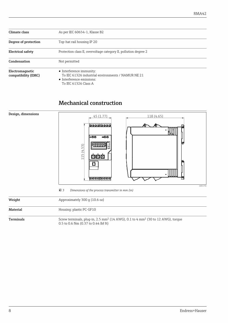
Mechanical construction
Design, dimensions
11
5 (
4.5
3)
45 (1.77) 118 (4.65)
A0011792
3 Dimensions of the process transmitter in mm (in)
Weight Approximately 300 g (10.6 oz)
Material Housing: plastic PC-GF10
Terminals Screw terminals, plug-in, 2.5 mm2 (14 AWG), 0.1 to 4 mm2 (30 to 12 AWG), torque0.5 to 0.6 Nm (0.37 to 0.44 lbf ft)

RMA42
Endress+Hauser 9
Operability
Local operation
1
2
3
4
5
6
7
8
A0011767
4 Display and operating elements of the process transmitter
1 HART® connection sockets2 Display3 Operating keys4 PC interface connection port5 Green LED; on = supply voltage applied6 Red LED; on = error/alarm7 Yellow LED; on = relay 1 energized8 Yellow LED; on = relay 2 energized
3
5
4 6
2
1
A0011765
5 Display of the process transmitter
1 Channel display: 1: analog input 1; 2: analog input 2; 1M: calculated value 1; 2M: calculated value 22 Measured value display3 Dot matrix display for TAG, bar graph and unit4 Limit value indicators in the bar graph5 "Operation locked" indicator6 Minimum/maximum value indicator
• Display5-digit, 7-segment backlit LC displayDot matrix for text/bar graph
• Display range-99999 to +99999 for measured values
• Signaling– Setup security locking (lock)– Measuring range overshoot/undershoot– 2 x status relay (only if relay option was selected)
Operating elements
3 keys: -, +, E
Remote operation Configuration
The device can be configured with the PC software or on site using the operating keys. FieldCareDevice Setup is delivered together with the Commubox FXA291 or TXU10-AC (see ’Accessories’) orcan be downloaded free of charge from www.endress.com.

RMA42
10 Endress+Hauser
Interface
4-pin socket for the connection with a PC via Commubox FXA291 or TXU10-AC interface cable (see'Accessories')
Certificates and approvals
CE mark The measuring system meets the legal requirements of the applicable EC guidelines. These are listedin the corresponding EC Declaration of Conformity together with the standards applied. Endress+Hauser confirms successful testing of the device by affixing to it the CE mark.
EAC mark The product meets the legal requirements of the EEU guidelines. The manufacturer confirms thesuccessful testing of the product by affixing the EAC mark.
Ex approval Information about currently available Ex versions (ATEX, FM, CSA, etc.) can be supplied by your E+HSales Center on request. All explosion protection data are given in a separate documentation whichis available upon request.
Overfill prevention WHG-compliant limit signal transmitter (optional)
Functional safety SIL2 (optional)
Marine approvals German Lloyd (GL, optional)
UL UL recognized component (see www.ul.com/database, search by keyword "E225237")
CSA CSA General Purpose (CSA GP)
Power station Seismic test according to KTA3505 (optional)
Other standards andguidelines
• IEC 60529:Degrees of protection provided by enclosures (IP code)
• IEC 61010-1:Safety Requirements for Electrical Equipment for Measurement, Control and Laboratory Use
• EN 60079-11:Explosive atmospheres - Part 11: Equipment protection by intrinsic safety "I" (optional)
Ordering informationDetailed ordering information is available from the following sources:• In the Product Configurator on the Endress+Hauser website: www.endress.com -> Click "Corporate"
-> Select your country -> Click "Products" -> Select the product using the filters and search field ->Open product page -> The "Configure" button to the right of the product image opens the ProductConfigurator.
• From your Endress+Hauser Sales Center: www.addresses.endress.comProduct Configurator - the tool for individual product configuration• Up-to-the-minute configuration data• Depending on the device: Direct input of measuring point-specific information such as
measuring range or operating language• Automatic verification of exclusion criteria• Automatic creation of the order code and its breakdown in PDF or Excel output format• Ability to order directly in the Endress+Hauser Online Shop

RMA42
Endress+Hauser 11
AccessoriesVarious accessories, which can be ordered with the device or subsequently from Endress+Hauser, areavailable for the device. Detailed information on the order code in question is available from yourlocal Endress+Hauser sales center or on the product page of the Endress+Hauser website:www.endress.com.
Communication-specificaccessories
Designation
Interface cable
Commubox TXU10 incl. FieldCare Device Setup and DTM Library
Commubox FXA291 incl. FieldCare Device Setup and DTM Library
Supplementary documentation• System components and data manager - solutions to complete your measuring point:
FA00016K/09• Operating Instructions for process transmitter RMA42: BA00287R/09• Ex-related additional documentation:
ATEX II (1)G [Ex ia] IIC, ATEX II (1)D [Ex ia] IIIC: XA00095R/09• SIL Safety Manual:
SD00025R/09

www.addresses.endress.com


![Q ;¤CeW27m[oRek¨Uì]Ë. .÷ Endress+Hauser * 2Ý...Endress+Hauser 中国 鸟瞰图 Endress+Hauser 工程师在现场 4 Q ;£CdW17l[nRdk Uë]Ê. .ö Endress+Hauser * 2Ý5 Endress+Hauser](https://img.dokumen.tips/doc/110x75/61269abbaa2e0357dc52fda9/q-cew27moreku-endresshauser-2-endresshauser-ec.jpg)