Embed Size (px)
Citation preview

Version 17.03.2021 RL-PCM3-2-TF
r.LiNK-Interface
RL-PCM3-2-TF
Rear and front camera input
incl. video-in-motion compatible with Porsche vehicles with PCM 3 and PCM 3.1 navigation systems
Product features • Plug and play interface • Integrated into the vehicle infotainment • Rear-view camera input (+ coding) • Front camera input • Rear-view and front camera power (+12V max. 1A) • Video-in-motion • Automatic switching to rear-view camera input • Optionally coding of ParkAssist to retrofit factory PDC

Version 17.03.2021 RL-PCM3-2-TF
Page1
Contents
1. Prior to installation
1.1. Delivery contents 1.2. Check compatibility of vehicle and accessories 1.3. Setting the DIP-switches of the Interface-Box RLC-M40-2 1.4. Pin-assignments
2. Connection schema
3. Installation
3.1. Interconnecting interface-Box, harness and factory head unit 3.2. Connections to after market rear-view camera 3.3. Connections to OEM rear-view camera 3.4. Connections to front camera
4. Coding of the camera function
4.1. Coding of the rear-view camera (only PCM3.1) 4.1.1. Decoding of the rear-view camera (only PCM3.1) 4.2. Optionally coding of ParkAssist to retrofit factory PDC (only PCM3.1) 4.2.1. Decoding of the ParkAssist (only PCM3.1) 4.3. Alternatively coding and decoding of rear-view camera and ParkAssist (e.g.
if steering-wheel buttons not existing, only PCM3.1) 4.4. Coding and decoding of rear-view camera (only Porsche Cayenne with PCM3) 4.5. LED information
5. Manually front camera activation
6. Specifications
7. Technical support
Legal Information
By law, watching moving pictures while driving is prohibited, the driver must not be distracted. We do not accept any liability for material damage or personal injury resulting, directly or indirectly, from installation or operation of this product. This product should only be used while standing or to display fixed menus or rear-view-camera video when the vehicle is moving, for example the MP3 menu for DVD upgrades.
Changes/updates of the vehicle’s software can cause malfunctions of the interface. We offer free software-updates for our interfaces for one year after purchase. To receive a free update, the interface must be sent in at own cost. Labor cost for and other expenses involved with the software-updates will not be refunded.

Version 17.03.2021 RL-PCM3-2-TF
Page2
1. Prior to installation
Read the manual prior to installation. Technical knowledge is necessary for installation. The place of installation must be free of moisture and away from heat sources. 1.1. Delivery contents
1.2. Check compatibility of vehicle and accessories
Take down the SW-version and HW-version of the interface boxes, and store this manual for support purposes.
Requirements
Vehicle Porsche Cayenne, Panamera, 911, Boxster, Cayman, Macan
Navigation PCM 3 (only Cayenne version) , PCM 3.1 (911, Boxster and Cayman only from software version 4.xx)
Limitations
Video-in-motion Internal DVD video cannot be watched!
Harness RLC-POR03-2
Interface-box RLC-M40-2 HW_____ SW_____

Version 17.03.2021 RL-PCM3-2-TF
Page3
1.3. Setting the DIP switches of the interface-box RLC-M40-2
Vehicle/ navigation DIP 1 DIP 2 DIP 3 DIP 4 DIP 5 DIP 6 PCM 3 with video-in-motion activated ON ON OFF OFF OFF OFF PCM 3 with video-in-motion deactivated OFF ON OFF OFF OFF OFF PCM 3.1 with video-in-motion activated ON ON OFF OFF OFF ON PCM 3.1 with video-in-motion deactivated OFF ON OFF OFF OFF ON
Note: DIP switch functions of the interface-box RLC-M40-2 DIP 1 – Activation video in motion DIP 2 – OEM- or aftermarket- rear view camera existing DIP 3 – Coding rear-view camera in conjunction with DIP 5 DIP 4 – Coding ParkAssist in conjunction with DIP 5 (only PCM3.1, PCM3 no function) DIP 5 – Camera / ParkAssist coding (DIP switch for 5 sec. in ON position) DIP 6 – CAN-bus termination
1.4. Pin-assignments Pin-assignment factory connector
No liability for vehicle wire colors and pin definition! Possible changes by the vehicle manufacturer. The given information must be verified by the installer. Pin-assignment of the interface-box RLC-M40-2 (Molex 12pin) Cable colour Pin-No. Assignment ● Yellow Pin 6 CAN-HIGH – connection to the head-unit ● Blue Pin 5 CAN-LOW – connection to the head-unit ●● Yellow/Black Pin 12 CAN-HIGH – connection to the vehicle ●● Blue/Black Pin 11 CAN-LOW – connection to the vehicle ● Red Pin 1 +12V permanent ● Black Pin 7 Ground ● Green Pin 2 +12V rear view camera output (max. 1A) ● White Pin 3 +12V front camera output (max. 1A) ● Blue Pin 4 No function ● Yellow Pin 8 Rear view camera video signal input ● Yellow Pin 10 Front camera video signal input ● Transparent Pin 9 Camera video signal output
Cable colour Assignment Pin No. ● Red +12V battery Pin 15 ● Black Ground Pin 12 ●● Orange/brown CAN-low Pin 9 ●● Orange/purple CAN-high Pin 11

Version 17.03.2021 RL-PCM3-2-TF
Page4
2. Connection schema
Version 17.03.2021 RL-PCM3-2-TF
Page5
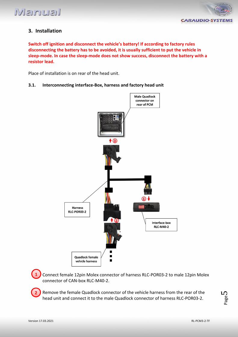
3. Installation Switch off ignition and disconnect the vehicle’s battery! If according to factory rules disconnecting the battery has to be avoided, it is usually sufficient to put the vehicle in sleep-mode. In case the sleep-mode does not show success, disconnect the battery with a resistor lead. Place of installation is on rear of the head unit. 3.1. Interconnecting interface-Box, harness and factory head unit
Connect female 12pin Molex connector of harness RLC-POR03-2 to male 12pin Molex connector of CAN-box RLC-M40-2. Remove the female Quadlock connector of the vehicle harness from the rear of the head unit and connect it to the male Quadlock connector of harness RLC-POR03-2.
2
1
Version 17.03.2021 RL-PCM3-2-TF
Page6
Connect female Quadlock connector of harness RLC-POR03-2 to the male Quadlock connector of the head unit.
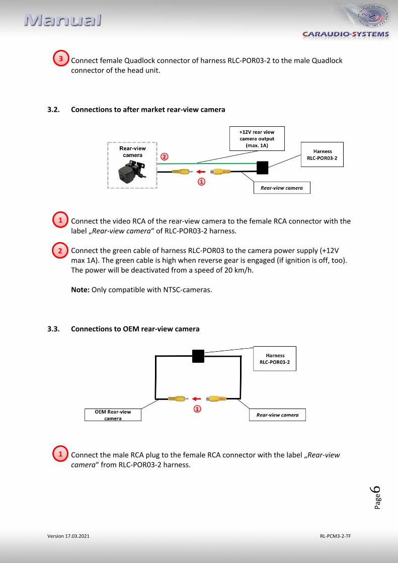
3.2. Connections to after market rear-view camera
Connect the video RCA of the rear-view camera to the female RCA connector with the label „Rear-view camera“ of RLC-POR03-2 harness. Connect the green cable of harness RLC-POR03 to the camera power supply (+12V max 1A). The green cable is high when reverse gear is engaged (if ignition is off, too). The power will be deactivated from a speed of 20 km/h. Note: Only compatible with NTSC-cameras.
3.3. Connections to OEM rear-view camera
Connect the male RCA plug to the female RCA connector with the label „Rear-view camera“ from RLC-POR03-2 harness.
1
3
2
1

Version 17.03.2021 RL-PCM3-2-TF
Page7
3.4. Connections to front camera
Connect the video RCA of the front camera to the female RCA connector with the label „Front-view camera“ of RLC-POR03-2 harness. Connect the white cable of harness RLC-POR03-2 to the camera power supply (+12V max 1A). The white cable is high when reverse gear is engaged (if ignition is off, too). The power will be deactivated from a speed of 20 km/h. Note: Only compatible with NTSC-cameras.
2
1

Version 17.03.2021 RL-PCM3-2-TF
Page8
4. Coding of the camera function 4.1. Coding of the rear-view camera (only PCM3.1) It is necessary to code the rear-view camera input of the PCM 3.1 to use it for an after-market rear-view camera.
1. Turn on ignition 2. Wait until the head-unit has booted 3. Press and hold steering-wheel button HASH KEY/MODE 4. Press and hold steering-wheel button ACCEPT (observe the sequence!) 5. Hold both buttons. During configuration the red and
blue LED are blinking short inside the CAN-box (visible at the male 8pin Molex connector). The PCM makes a reset after 5-10 sec.
6. Disengage both steering-wheel buttons 7. The red and the blue LED inside the CAN-Box are
glowing and the menu „Rear-view camera“ appears in the menu OPTION after a successful coding
4.1.1. Decoding of the rear-view camera (only PCM3.1) It is possible to decode the coding of the rear-view camera input as follows:
1. Turn on ignition 2. Wait until the head-unit has booted 3. Press and hold steering-wheel button HASH KEY/MODE 4. Press and hold steering-wheel button HANG UP (observe the sequence!) 5. Hold both buttons. During configuration the red and blue LED are blinking inside the
CAN-box (visible at the male 8pin Molex connector). The PCM makes a reset after 5-10 sec.
6. Disengage both steering-wheel buttons 7. The red and the blue LED inside the CAN-Box are glowing and the menu „Rear-view
camera“ disappears in the menu OPTION after a successful decoding
Steering-wheel buttons left Steering-wheel buttons right
BACK
HANG UP
HASH KEY/MODE
ACCEPT
Version 17.03.2021 RL-PCM3-2-TF
Page9
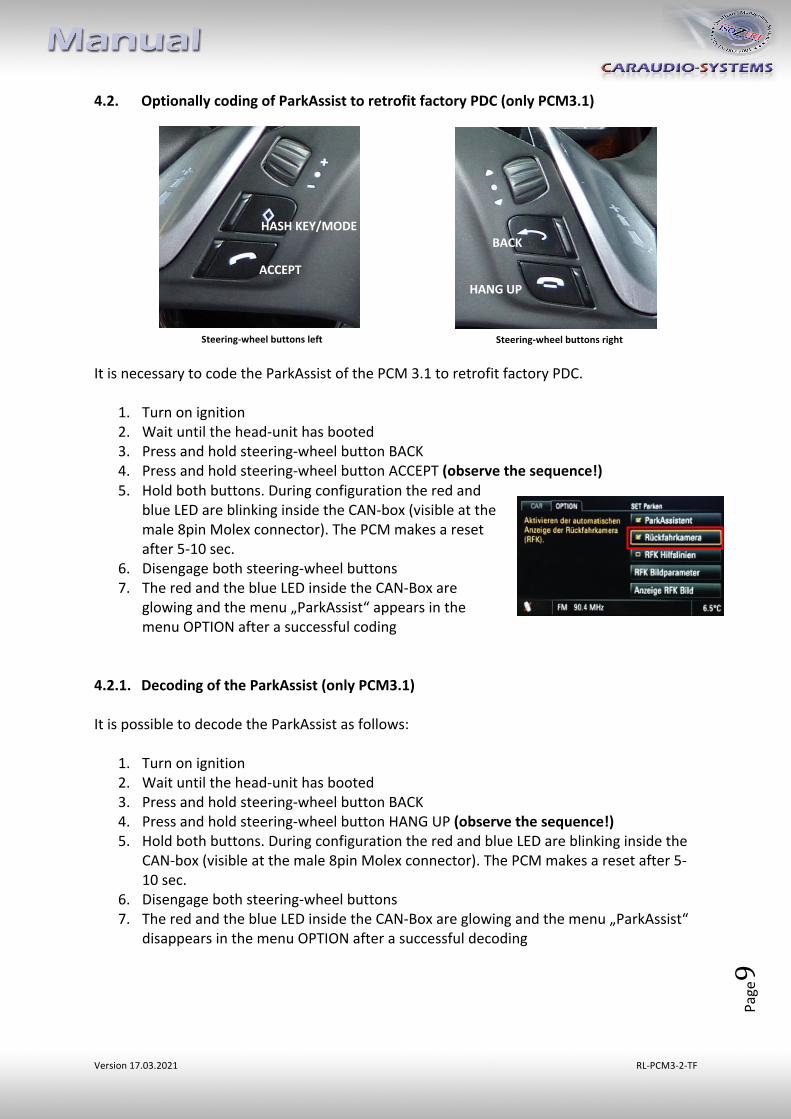
4.2. Optionally coding of ParkAssist to retrofit factory PDC (only PCM3.1) It is necessary to code the ParkAssist of the PCM 3.1 to retrofit factory PDC.
1. Turn on ignition 2. Wait until the head-unit has booted 3. Press and hold steering-wheel button BACK 4. Press and hold steering-wheel button ACCEPT (observe the sequence!) 5. Hold both buttons. During configuration the red and
blue LED are blinking inside the CAN-box (visible at the male 8pin Molex connector). The PCM makes a reset after 5-10 sec.
6. Disengage both steering-wheel buttons 7. The red and the blue LED inside the CAN-Box are
glowing and the menu „ParkAssist“ appears in the menu OPTION after a successful coding
4.2.1. Decoding of the ParkAssist (only PCM3.1) It is possible to decode the ParkAssist as follows:
1. Turn on ignition 2. Wait until the head-unit has booted 3. Press and hold steering-wheel button BACK 4. Press and hold steering-wheel button HANG UP (observe the sequence!) 5. Hold both buttons. During configuration the red and blue LED are blinking inside the
CAN-box (visible at the male 8pin Molex connector). The PCM makes a reset after 5-10 sec.
6. Disengage both steering-wheel buttons 7. The red and the blue LED inside the CAN-Box are glowing and the menu „ParkAssist“
disappears in the menu OPTION after a successful decoding
Steering-wheel buttons left Steering-wheel buttons right
BACK
HANG UP
HASH KEY/MODE
ACCEPT

Version 17.03.2021 RL-PCM3-2-TF
Page10
4.3. Alternatively coding and decoding of rear-view camera and ParkAssist (e.g. if
steering-wheel buttons not existing, only PCM3.1) Alternatively to coding by steering-wheel buttons the coding and decoding of rear-view camera and ParkAssist can be done by DIP 5 in conjunction with DIP 3 and 4 of interface-box RLC-M40-2.
1. Set DIP switch “5” to OFF position 2. Turn on ignition 3. Wait until the head-unit has booted 4. Set DIP “3” and DIP “4” of CAN-box (depending on the desired coding/decoding) 5. Set DIP switch “5” for 5 sec. to ON position 6. During configuration the red and blue LED are blinking
short inside the CAN-box (visible at the male 8pin Molex connector). The PCM makes a reset after 5-10 sec.
7. The red and the blue LED inside the CAN-Box are glowing and the menu „Rear-view camera“ respectively “ParkAssist” appears in the menu OPTION after a successful coding (or disappears after successful decoding)
Note: After a coding or decoding another coding isn’t possible within the next 60 seconds! If there are factory-PDC existing in the car you have to set DIP 4 to ON while coding. If not the factory PDC will be decoded!
DIP Function ON OFF DIP 3 Rear-view camera Coding Decoding DIP 4 ParkAssist Coding Decoding DIP 5 Activation of the coding/decoding process 5 sec. = start Default setting
BACK

Version 17.03.2021 RL-PCM3-2-TF
Page11
4.4. Coding and decoding of rear-view camera (only Porsche Cayenne with PCM3)
The rear-view camera coding and decoding can be done by DIP 5 in conjunction with DIP 3 of interface-box RLC-M40-2.
1. Set DIP switch “5” to OFF position 2. Turn on ignition 3. Wait until the head-unit has booted 4. Set DIP “3” of CAN-box (depending on the desired coding/decoding) 5. Set DIP switch “5” for 5 sec. to ON position 6. During configuration the red and blue LED are blinking short inside the CAN-box
(visible at the male 8pin Molex connector). The PCM makes a reset after 5-10 sec.
7. The red and the blue LED inside the CAN-Box are glowing and the menu „Rear-view camera“ appears in the menu OPTION after a successful coding (or disappears after successful decoding)
Note: After a coding or decoding another coding isn’t possible within the next 60 seconds!
4.5. LED information
5. Manually front camera activation Press the HANG UP button on the steering wheel for 3 sec. for manually front camera activation / deactivation.
DIP Function ON OFF DIP 3 Rear-view camera Coding Decoding DIP 5 Activation of the coding/decoding process 5 sec. = start Default setting
LED Status Explication
Blue Lights CAN bus communication OK Flashes CAN bus search
Red Lights - Interface active
- Rear-view camera/ParkAssist successfully coded / decoded
Off - Interface sleep - Error in the Rear-view camera/ParkAssist coding process
HANG UP
Version 17.03.2021 RL-PCM3-2-TF
Page12
6. Specifications Operation voltage 10.5 – 14.8V Stand-by power drain <2mA Operation power drain ~60mA Power consumption ~0,08W Temperature range -30°C to +80°C Weight 44g Measurements (box only) W x H x D 70 x 20 x 47 mm/ 76 x 27 x 54 mm 7. Technical support
Caraudio-Systems Vertriebs GmbH manufacturer/distribution
In den Fuchslöchern 3 D-67240 Bobenheim-Roxheim
email [email protected]
Legal disclaimer: Mentioned company and trademarks, as well as product names/codes are registered trademarks ® of their corresponding legal owners.