Embed Size (px)
Citation preview

OUTLIHE15-115-2
15-315-415-515ÿG
Review of simple R and L circuitsUsing vectors to describe and determine magnitudeand directionIntroduction to basic ac circuit analysis techniquesFundamental analysis of series RL circuitsFundamental analysis of parallel RL circuitsExamples of practical applications for inductorsand RL circuits
OBJECTIVES
After studying this chapter, you should be able to:
]. Use vectors to determine magnitude anddirection
2. Determine circuit impedance using thePythagorean theorem
3. Determine VT and IT using the Pythagoreantheorem
4. Determine ac circuit parameters usingtrigonometry
5. Calculate ac electrical parameters for seriesRL circuits
6. Calculate ac electrical parameters for parallelRL circuits
7. List at least three practical applications ofinductive circuits
8. Use the computer to solve circuit problems9. Use the SIMPLER troubleshooting sequence to
solve the Troubleshooting Challenge problem
CHAPTER 15
RL Circuits in AC
L .....
403

PREVIEW
n the preceding chapters, you have studied the circuit characteristics of both dc and accircuits containing only inductance. You have learned basic concepts related to induc-
tors, such as inherent opposition to current changes, the seff-induced back-emf, phaserelationships of V and I, and other characteristics of inductance.
The purpose of this chapter is to introduce you to basic facts and circuit analysis tech-niques used to examine ac circuits containing both resistance and inductance (RL cir-cuits). Impedance, a combination of resistance and reactance, will be discussed andanalyzed. Further considerations about phase angle will be given. Primary methodsof using vectors and other simple math techniq.ues to analyze RL circuit parameters wialso be introduced. Later in the text, you will study vector analysis techniques that involvepolar and rectangular coordinate systems, and methods of expressing electrical quanti-ties using these systemsl For this chapter, however, we simply want to introduce you tobasic concepts related to analyzinq RL circuits in ac.
The concepts discussed in this chapter are important because they provide valuableknowledge far all your future ac circuit analvses endeavors This chaoter beains a seriesof chapters in whic" h you will be performing'calculator operations such as square roots,squares, trigonometric functions, and so on. We want to remind you that different mod-els of scientific calculators may use slightly different keystrokes for certain operations. Asyou get involved in this chapter, study and/or refer back to the "Special Notations Re-garding Scientific Calculators" chart found on the CD provided with t'his text, as required.
I(EY TERMS
Cosine functionImpedancePhase angle (8)Pythagorean theorem
ScalarSine functionTangent functionVector
] 5-1 Review of Simple R and L Circuits
Simple R CircuitThe ac current through a resistor and the ac voltage across a resistor are in phase, as you havealready learned. You know this may be shown by a waveform display or phasor diagram, Fig-ure 15-1.
In the purely resistive series ac circuit, Figure 15-2a, you simply add the individual seriesresistances to find total circuit opposition to current. Or you add voltage drops across resis-tors to find total circuit voltage, since all voltage drops are in phase with each other.
In purely resistive parallel circuits, Figure 15-2b, total resistance is found by using theproduct-over-the-sum or reciprocal methods. The total circuit current is found by adding thebranch currents, because all branch currents are in phase with each other.
FIGURE ! 5-1simple R circuit
V and I in a
Z
avefo m dis ayl Circuit diagram
V I
i
i

CHAPTER 15 . RL Circuits in AC 405
FIGUR[ 15-2- Purely resistivecircuits
(a)
IT= Ii÷ I2 i
(b)
V I
iWaveform displayI
(a)
i ÿi:Ctiit aiaÿam-i ÿpfi&or-ai-agramI
(b)
FIGURE 15-3 V and I in asimple L circuit
VT
(a) (b)
i LT=LI+L2 !+ xL2i
! vr=v,+v2 i
FIGIJR[ 15-4 Purely inductivecircuits
Simple L CircuitIn a purely inductive ac circuit, you know that current through the inductor and voltage acrossthe inductor are 90° out of phase with each other. Again, this is illustrated by a waveform dis-play, Figure 15-3a, or a phasor diagram, Figure 15-'3b.
You know that in purely inductive series circuits, total inductance is the sum of the indi-vidual inductances; total inductive reactance (Xÿ) is the sum of all Xrs; and total voltageequals the sum of all VLs, since each Vr is in phase with the other VLs although they are notin phase with the current, Figure 15-4a. In purely inductive parallel circuits, total circuit op-position to current (X!r) is found by using redprocal or product-over-the-sum approaches.Also, total circuit current equals the sum of the branch currents, since branch currents are inphase with each other although not in phase with the circuit voltage, Figure 15-4b.

406 PART IV • Reactive Components
] 5-2 Using Vectors to Describe and Determine Magnitude and Direction
Background
When ac ch'cuits contain both reactances and resistances, their voltage(s) and cun'ent(s) arenot in phase with each other. In this case, we cannot add these quantities together to find re-sultant totals as we did with dc circuits or ac circuits that are purely resistive or reactive. There-fore, other methods are used to analyze ac circuit parameters.
One of these methods is to represent circuit parameters using vectors. A vector quantity ex-presses both magn&fde and direction. Examples of quantities having both magnitude and dflec-tion that are illustrated using vectors include mechanical forces, the force of gravity, wind velocityand dh'ection, and magnitudes and relative angles of electrical voltages and cmTents in ac.
Scalars, on the other hand, define quantities that exhibit only magnitude. Units of mea-sure, such as the henry or the ohm, are scalar quantities. Even dc circuit parameters, o1" in-stantaneous values of ac electrical quantities are treated as scalar quantities, since there areno time differences or angles involved. Simple addition is used to add scalar quantities, butthis is not true for vector quantities.
Plotting and Measuring Vectors
Vectors can be plotted to scale to determine both magnitude and direction of given quanti-ties, Figure 15-5. If a force of 10 pounds is exerted on Rope i and a force of 10 pounds is exertedon Rope 2, what is the total force exerted on the weight, and in which direction is this total force?The resultant force is 14.14 pounds in a direction that is 45° removed from either rope's direction.
Look at Figure 15-6. Notice these vectors are plotted to scale so you can then measureboth the magnitude and direction of the resultant force. Measure the length of the resultantvector to find magnitude, and measure the angle between the original forces and the resul-tant force by a protractor to find direction.
FIGURE 15-5 Vectors showboth magnitude and direction.
01bs
Rope 1
Weight
/45o ;Rope 2
114' 14 l bs ..... :
10 lbs
10 units
unitsÿ
FIGURE 15-6 Plotting vectorsto scale
(10 units)
Protractor
0 = As?
j 10 units

CHAPTER 15 . RL Circuits in AC 407
Head-tp-ta!iI ;ParaHeiqgrmÿ14.14
14.14 10 10
>110 10
(a) (b)
FIGURE 15-7 Methods offormatting vectors
Observe Figure 15-7a, which illustrates how vectors are laid end-to-end or head-to-tail todetermine resultant values. Also, notice in Figure 15-7b that a parallelogram is drawn thatprojects the same magnitudes as the end-to-end approach. Although either method can beused to find resultant values, we will use the parallelogram approach most frequently.
Later in the chapter you will see how this plotting and measuring technique is used to an-alyze RL circuit parameters. Although it is not always convenient to have graph paper andprotractor handy, or to draw circuit parameters to scale when analyzing a circuit, the plottingapproach can be used. Also, it is a useful tool to help introduce you to vectors.
Even when not plotted to scale for the direct measurement method, vectors are usefulto illustrate ac circuit parameters and show relative magnitudes and angles. Sketching thisdiagram helps you understand the situation and verify your computations.
Practical Notes
PRACTICE PROBLEMS 1Assume the forces on the ropes in Figure 15-5 are 3 pounds for Rope 1 and 4 pounds forRope 2. What are the magnitude and direction of the resultant force on the weight? (NOTE:Use the plotting-to-scale approach and remember to keep things relative to the scale you use.)
Even when not preciselymeasuring vectors todetermine resultant values,get in the habit ofapproximating the relativelengths and directions ofvectors when you drawthem to solve ac problems.This allows you to visuallydetermine if yourcomputations are makingsense! A good practice is todraw simple vectordiagrams whenever you areanalyzing ac circuits theyhelp visualize the situation.
[] IN-PROCESS LEARNING CHECK 1
1. In a purely resistive ac circuit, the circuit voltage and current are __ phase.
2. In a purely inductive ac circuit, the current through the inductance and the voltage acrossthe inductance are __ degrees out of phase. In this case, the __ leads the __.
3. A quantity expressing both magnitude and direction is a__ quantity.
4. The length of the vector expresses the __ of a quantity.[]
] 5-3 Introduction to Basic AC Circuit Analysis Techniques
Most ac circuit analyses solve for quantities that are illustrated with vectors in right-triangleform. Recall fi'om our previous discussions that a right triangle has one angle forming 90°and two angles that total another 90°, Figure 15-8. Many electrical parameters have this 90°phase difference between quantities. For example, in perfect inductors and capacitors, thevoltages and currents are 90° out of phase. Also, ac circuit resistive and reactive voltage dropsor currents are often represented as 90° out of phase with each other.
p oactica NotesNOTE: The calculations are easy if you have a commonly used scientific calculator withsquare, square root, and "trig" function keys. You probably own or presently have access tosuch a calculator. If not, you might want to gain access to one and learn to use these functionsas you proceed through the remainder of the chapter. If this device is not available, paper andpencil will work just fine! NOTE: Be aware that some calculators only accept radianmeasure! Therefore, to convert degrees to number of radians, divide the number of degrees by57.3; and to convert radians to number of degrees, multiply the number of radians by 57.3.Recall that 27t radians equal 360°; that is, 6.28 times 57.3° equals 360°.

408 PART IV • Reactive Components
FIGURE 15-8 Examples offight triangles
60° 90°
We will discuss two basic techniques used to analyze these fight-triangle problems. Thefirst method is the Pythagorean theorem, which is useful to determine the magnitude ofquantities. The other method briefly addressed in this chapter is trigonometric functions thatdetermine the circuit phase angles. Also, tfigonometry can be used to find the magnitude ofvarious electrical quantities, if the phase angle is known.
Pythagorean TheoremThe Pythagorean theorem states that the square of the hypotenuse of a fight triangle equalsthe sum of the squares of the other two sides.
FORMULA 15-1 c2 = a2 + b2
bc2 = a2 + b2
:c = ÿff+ b2}
V2 --I
FIGURE 15-10
v125 Vi
t--!svl Vo/ÿJ -ÿ[/ÿ [!
_-
V >1
= r5 V
FIGURE 15-11
iVs= ?
FIGURE 15-9 Pythagoreantheorem
Refer to Figure 15-9 and review the equations related to the fight triangle and Pythagoreantheorem.
Now, let's transfer this information into finding the resultant value, or magnitude, oftwo voltages that are displaced from each other by 90° and vectorially added.
[] EXAMPLE Refer to Figure 15-10 and observe the following steps: In the diagramshown,
1. Vs represents the hypotenuse of the right triangle.
2. !71 represents one of the other two sides of the fight triangle.
3. V2 represents the remaining side of the right triangle.
4. TransfeiTing this information into the Pythagorean formula:
Vs = ÿ!-VÿI2 + v22
Vs = a/252 +25z
Vs = -]1,,250 = 35.35 V []PRA(II(E PROBLENS 2
Refer to Figure 15-11. Use the Pythagorean theorem and solve for the magnitude of side Vs.
igonolnetric FunctionsTrigonometric functions result from special relationships existing between the sides and an-gles of right triangles. "Trig" is a common shortened term for trigonometry or trigonomet-
L

CHAPTER 15 ', RLCircuitsinAC 409
tic. We will only discuss three basic trig functions used for your study of ac circuits--sine,cosine, and tangent functions.
Notice the side opposite (opp), the side adjacent (adj), and the hypotenuse (hyp) in Fig-ure 15-12. As you can see, the relationship of each side to the "angle of interest," 0, deter-mines whether it is called the opposite or the adjacent side. The hypotenuse is always thelongest side of the triangle.
Refer to Figure 15-12 to review the basic trig functions.If we assume a rotating vector with a unit length of one starts at 0° and rotates counter-
clockwise to the 90° position, the values of sine, cosine, and tangent vary within limits.That is:
sin 0 increases from 0 to 1.0 (with angles from 0° to 90°)cos 0 decreases from 1.0 to 0 (with angles from 0° to 90°)tan 0 increases from 0 to ÿo (with angles from 0° to 90°)
See if you can relate this to the sine and cosine waves in Figure 15-13. Assume the maxi-mum (peak) value is one volt for each waveform, Relate the zero points and the maximumpoints to the angles. Do they compare?
Figure 15-14 carries this idea one step further. Notice how these functions vary in the fourquadrants of the coordinate system we discussed in an earlier chapter. Again, try relating thesine and cosine waves in Figure 15-13 to the statements in Figure 15-14.
Hypotenuse
ic
bÿSide adjacent to 0i
Side sin 0 opp......... i - hyp
2/i 01iopposite--J2
cos 0 =
tan 0- oppadj FIGURE 15-12 Labeling sides
of a right trianglea a
sin 0 = c;a= csinO;c= sinO
cos 0=O'b=ccos0;c=b
C ' COS 0
a atan 0 = 7:a=btanO;b= 0O" tan
Cosine
\
Sine
0.5
-1
0oI I I
45°
\\
I:i
--0.5 -
\\\\'\\\\\\\\\
\
I I I I I90° 135°
1I
iI!
I I I I I180° 225°
t/
/
/
//
//
!/
I I I I I270° 315° 360°
FIGURE 15-13 Sine andcosine waves
410 PART IV • Reactive Components
[] EXAMPLE What is the described angle if the side opposite is 2 units and the hypotenuseis 2.828 units?
Referring to the trig formulas for sine, cosine, and tangent, the trig formula containing theside opposite and the hypotenuse is the formula for the sine of the angle. Therefore,
2sin 0 = -- = 0.7072.828
The sin-1 of 0.0707 = 45°.Now try the following practice problems. []
PRh(TKE PROBLEMS 31. What is the described angle if the side adjacent has a magnitude of 5 units and the hy-
potenuse has a magnitude of 10 units?
2. What is the tangent of 45°?
3. What is the sine of 30°?
9'
15-4 Fundamental Analysis of Series RL Circuits
Now we will take the knowledge you have acquired and apply it to some practical situationsand problems, so you can see the benefit of this knowledge!
Refer to Figure 15-15. Notice that if you added the voltages across the series resistor andthe inductor to find total applied voltage, you would get 20 V. This answer is wrong ! The ac-tual applied voltage]s 14.14 V.
Let's see why 20 V is the wrong value! Recall in series circuits, the current is the samethrough all components. Again referring to Figure 15-15 and from our previous discus sions,we know the voltage across the resistor is in phase with the current. We also know the volt-age across the inductor leads the current by about 90°, which means the voltages across theresistor and the inductor are not in phase with each other. Since the current through both isthe same current, one voltage is in phase with the current (VR), and one voltage is not inphase with the current. Therefore, we cannot add the voltages across R and L to find total
QUADRANT
I (0° to 90°)II (90° to 180°)III (180° to 270°)1V (270° to 360°)
COS 0 .... TAN'0
FROM TO : FROM : TO
1.0 0 !: 0 ; • 0o {0 -1.0 ? :2ÿ ÿ 0 J-1.o o io 1.o 0 ]
f
FIGURE 15-14 Variations in values of trig functions
14.14V ,)
R '10 V
FIGURE 15-15 Series RL circuit voltages

CHAPTER 15 * RL Circuits in AC 411
voltage, as we would do in a simple dc circuit. Rather, we must use a special method of ad-dition called vector addition to find the correct answer. The voltages must be added "vecto-rially," not "algebraically."
Let's try the two methods previously discussed to find total voltage in series RL circuits.
Using the Pythagorean Theorem to Analyze Voltagein Series RL Circuits
Figure 15-16 illustrates how VR, VL, and Vr are typically represented in a fight triangle byphasors or vectors.
[] EXAMPLE Let's transfer the Pythagorean theorem formula in Figure 15-9,c = ÿ + b2 , to this situation. As you can see, the longest side is Vr. This is equivalent tothe c in the original Pythagorean formula. The other two quantities (VR and VL) are the otherquantities in the formula. Thus, the formula to solve for Vr becomes:
FORMULA 15-2 Vr = ÿ/V2 + VZ
Therefore, Vr = la/iO;+10z =a/2ÿ=14.14 volts. []
[] EXAMP[[ Assume the voltage values in Figure 15-15 change so that VR is 30 volts andVL is 40 volts. What is the new V applied value?Answer." The Vris 50 volts, Figure 15-17. []
, PRA¢TI(:[ PROBL[MS 4
In a simple series RL ch'cuit, VR is 120 V and VL is 90 V. What is the V applied value? SUG-GESTION: Use your calculator.
You can see that, using the Pythagorean theorem, it is easy to find the magnitude of totalvoltage in a series RL circuit--simply substitute the appropriate values in the formula. Weare not able to find the resultant angular direction by this method. However, the trig functionshelp us.
Practical NotesFor series circuits, since current is common to all parts, current is commonly the referencephasor and is plotted on the reference phasor 0° axis.
...... I
il°v!l/0 I__.2_._+f
10V
VT= 14.14 V
....... ÿ Vr = 50 V ! ......
I /I IVT='VÿVR2q- VL2 i: ' kv .= vgoo + 1,6ooivLÿ (vL = 4ov)[
¢ !vr = 5o vVR : .....
130 Vÿ(NOTE: VTiS notequal to the sumof VR and VL. It is greater than eitherone alone, but not equal to their sum.)
FIGURE 15-16 Voltage vector diagram FIGURE 15-17

412 PART IV * Reactive Components
Using Trig to Solve for Angle Information in Series RL Circuits
Look at Figure 15-18 as you study the following statements.
1. To find the desired angle information using trig functions, identify the sides of the righttriangle in terms of the circuit parameters of interest. Note in Figure 15-18 that VL is inthe upward (+90°) direction, and VR is at the 0° reference direction. In series circuits, thecurrent is the same throughout the circuit and is in phase with the resistive voltage. There-fore, I is also on the 0° axis.
Because these directions are important, let's restate them! They are general rules ofthumb that you will use from now on! VL is vertical (up), VR is horizontal to the right, andI is in phase with VR.
2. Referring to the values in Figure 15-18, let's find the circuitphase angle that is defined as thephase angle between cilvuit applied voltage and circuit total current.
a. Consider the angle between Vr and Ir the angle of interest. Thus, the side opposite tothis angle is the VL value and the hypotenuse is Vr.
b. Use the information relating these two sides in the sine function formula to find the an-gle. (Recall that sin O= opp/hyp.) Therefore, in our example, sin O= 30/50 = 0.60.
c. Using a calculator, computer, or trig table, to find the angle having a sine function valueof 0.60, we find that it is 36.9°.
Practica Notes ÿn ac circuits containing both resistance and reactance, thephase difference in degrees between applied voltage and total current must fall between 0°(indicating a purely resistive circuit) and 90° (indicating a purely reactive circuit). Since bothresistance and reactance are present, the circuit cannot act purely resistive or purely reactive.
PiCa CtiCa ÿ N Ores Rather than having to say in words "the angle having a tangentvalue equal to . . . ," it is common to use the mathematical term "arc tangent," or "arctan." Inother words, if I find the arctan of 0.75, it is an angle of 36.9°. You will also see arctan written as"tan-l.'' To find the arctan on a calculator, input the ratio of the opposite side to the adjacent side.That is: (opposite side value, E], adjacent side value, E]), then press the ÿ and [rAN-,] functionkeys (in that order). You will then see the tan-1 (arctan, or angle value) displayed in the readout.
Naturally, you can find the arc sine or arc cosine using the same technique. For the sine,the values to input are the opposite side divided by the hypotenuse. For the cosine, the valuesto input are the adjacent side divided by the hypotenuse. Once you have the sine or cosinevalue, use the ÿ and [SIN-1] function keys or the [ghÿ and [¢0S-ÿ] function keys as appropriateto find the arc sine or arc cosine, respectively. (NOTE: This gives you the angle value.)
3ov 136"9° ) I
T adj VRiPhase angle
)
40 V
VT= 50V , ...........
Sin 0 = ÿ-ÿ OR VLVT
( VL) 30opp Sin 0 = 5-0 OR 0.60
Angle whose sine equalsIT 0.60 = 36.9°
o ÿ- g6:9o
NO;rE: Phase angle is considered the angular difference in phasebetween circuit total Voltage and circuit total currenL Get in ÿehabit of looking at the sketch to see if the answer is logical. !ÿisobvious that the angle in this case must be less than 45° becausethe vertical leg is shorter than the horizontal leg. The answer looksand seems logical!
FIGURE 15-18 Using trig to find angle information

CHAPTER i 5 ,, RL Circuits in AC 4 ] 3
d. In this example, since we know all sides, we can also use the other two trig functions.That is,
cos o= adj = -- = -- =VR 40 0.8hyp Vr 50
The angle with a cosine value of 0.8 is 36.9°.
tan 0 = °P-2 = =__3° = 0.75adj VR 40
The angle with a tangent value of 0.75 is 36.9°.
e. Use the sine, cosine, or tangent functions to solve for the unknown angle depending onthe information available. Obviously, when you know the values for the opposite sideand the hypotenuse, use the sine function. When you know the values for side adjacentand the hypotenuse, use the cosine function. When you know only the values for sideopposite the angle of interest and the side adjacent to the angle of interest, use the tan-gent function.
Stated another way, select and use the formula containing the two known values and the valueyou are solving for.
PRAUKE PR01ÿtEOaS 51. Draw the vector diagram for the voltages in Figure 15-19.
2. Use trig and solve for the phase angle of the circuit in Figure 15-19.
3. Which trig function did you use in this case?
4. If the voltages had been reversed (i.e., VR = 20 V and VL = 30 V), would the phase anglehave been greater, smaller, or the same?
Using Trig to Solve for Voltages in Series RL CircuitsYou have seen how trig helps find angle information. You have also learned that thePythagorean theorem is useful to find magnitude or voltage value in series RL circuits. Cantrig also be used to find magnitude? Yes, it can[ Let's see how[
[] EXAMPLE If the angle information is known, determine the sine, cosine, or tangent val-ues for that angle. Next, use the appropriate, available sides information, and find the value ofthe unknown side. Look at Figure 15-20 and let's see how to do this.
1. Start by making sm'e the formula for the trig function used includes the unknown side ofinterest, plus a known side. This allows us to solve for the unknown by using equationtechniques.
,9RtVR=30V I °°V i
IX0 = 60°IV\ ,ÿJ
.ÿ.ZrVR
Sin0 - V:r
VzSin 0 - 100
VLSin 60° = i06
VL0.866 =
86.6V = VLvRCos 0 = --,VrVR
0.5 = lo-ÿ
5ov = ÿ
FIGURE 15-19 ÿIÿIuILÿSIM FIGURE 15-20

414 PART IV • Reactive Components
2. To solve for VL, use the sine function since sin Ouses the opposite side divided by the hy-poteuuse. VL is the unknown side of interest and is the side opposite the known angle.Since we know the hypotenuse value, we have our starting point.
3. Sin 0= opp/hyp, thus sin 60° = VL/IO0. Now we determine the sine of 60° and substitutein the equation. Use the trig table, calculator, or computer and find the sine of 60° is 0.866.(NOTE: Round off to 0.87) Put this in the formula, 0.87 = VL/IO0. Transpose and solve:VL = 100 X 0.87 = 87 V.
4. To solve for VR, use either the cosine or tangent functions with the information nowknown. Cosine uses the adjacent divided by the hypotenuse, and tangent uses the oppo-site divided by the adjacent. In either case, a known and the desired unknown (the adja-cent) values appear in the formulas.
5. Assuming we do not know the VL value, we use the cosine function. Cos 0 = adj/hyp, there-fore cos 60° - VR/100. Next, determine the cosine of 60°, which equals 0.5. Substitute inthe formula, 0.5. = VR/100. Transpose and solve: VR = 100 X 0.5 = 50 V.
?
Now, let's see if these results make sense with respect to our vector diagram in Figure 15-20.Since the angle is greater than 45°, we know VL must be greater than VR and it is!
Now we can use the tangent function to check our results, since it uses the opposite di-vided by the adjacent sides. Insert the values found for VL and VR into thetan 0 = opp/adj formula to find that 86.6/50 = 1.732. The angle whose tangent is 1.732 is 60°;that is, the arc tan (tan-1) of 1.732 = 60°. It checks out! Now, you try some problems. []
PI1/KTI(E PROBL[IÿS 61. A series RL circuit has one resistor and one inductor. What is the VR value if the applied
voltage is 50 V and the circuit phase angle is 45°?
2. A series RL circuit composed of a single resistor and inductor has an applied voltage valueof 65 V and the circuit phase angle is 60°.
a. What is the value of VR?
b. What is the value of VL?
3. A series RL circuit composed of a single resistor and inductor has values where VL = 36 Vand VR = 24V.
a. What is the value of the angle between VR and VT?
b. What is the value of VT?
Analyzing Impedance in Series RL CircuitsYou have learned how to analyze various voltages in series RL circuits by measuring vectors,using the Pythagorean theorem, and applying basic trig functions. Now, let's look at anotherimportant ac circuit consideration: impedance.
Impedance is the total opposition a circuit offers to ac current flow at a given frequency. Thismeans impedance is the combined opposition of all resistances and reactances in the circuit.Since impedance is sensitive to frequency, there must be some reactance-pure resistance is notsensitive to frequency. The symbol for impedance is "Z," and the unit of impedance is the ohm.
Before discussing impedance, let's review some important facts you already know,Figure 15-21.
1. The voltage drop across the resistor is in phase with the circuit current through the resistor,and VR equals IR. Note that this is a series circuit. Since current is the common factor in se-ries circuits, the current is the reference vector and is at the 0° position of the coordinatesystem. Also, VR is at 0° since it is in phase with/.
2. The voltage drop across the inductor leads the circuit current by 90° (assuming a perfectinductor with no resistance), and VL equals !XL. Since VL leads I by 90°, the !XL vector isleading the I vector by 90°.
3. As you know, total circuit voltage is the vector resultant of the individual series voltages.Since the circuit is not purely resistive, nor purely inductive, the resultant circuit phase an-

CHAPTER 15 * RLCircuitsinAC 415
=ZZ
R
I
Phaseangle
0
vR= m"IT
FIGURE 15-21 SeriesRLcircuit quantities
FIGURE 15-22 An impedancediagram
0
gle between circuit Vand circuit !is between 0° and 90°. Also, as you can see from the di-agram, total circuit voltage equals IZ, where Z is the total opposition to ac current from thecombination of resistance and reactance. Since Iis at 0° and IZis at an angle between 0° and90°, when we plot Z, it also will be between 0° and 90°.
Let's pursue these thoughts. Refer to Figure 15-22 as you study the following discussionabout how to plot a diagram of R, XL, and Z (impedance diagram) for series RL circuits.
1. The VR equals IR, and I is plotted at the 0° reference vector position. Also, since the resis-tor voltage is in phase with the current through the resistor, R is plotted at the 0° referenceposition when plotting an impedance diagram of R, XL, and X
2. Since VL equals IXL and VL is plotted at 90° from the reference vector position, it is logi-cal that XL is plotted at the 90° position when plotting R, XL, and Z on an impedance dia-gram. Thus, the result of I times Xr is plotted at 90°.
3. The VT equals IZ, and VT is plotted at an angle (depending on the vector resultant of VRand VL) between 0° and 90°. Then it is logical to plot Z at the same angle in an impedancediagram where VT is plotted in the voltage diagramof the same series RL circuit. In fact,the angle between Z and R is the same as the circuit phase angle between VT and IT.
Knowing all this, how can the techniques to analyze voltages in series RL circuits be appliedto impedance? As you can see by comparing the diagrams of Figures 15-21 and 15-22, thelayout of the impedance diagram looks just like the diagram used in the voltage vector dia-gram analysis. This implies the techniques,used to find impedance (Z) are those techniquesused to find Vr. Recall that these methods include:
1. Draw to scale and measure to find magnitude and direction.
2. Apply the Pythagorean theorem to find magnitudes.
3. Apply trig functions to find angles or magnitudes.

416 PART IV * Reaclive Components
[] EXAMPLE Figure 15-23 illustrates the drawing-to-scale approach. Figure 15-24 showsthe Pythagorean theorem version used for impedance solutions as shown in Formula 15-3. []
j,'
FORMULA 15-3 Z = ÿ!R2 + X[
Finally, Figure 15-25 solves for the angle using the simple trig technique. Now you try ap-plying these techniques in the following situation.
2ÿ
?Q;
PI]A(II([ PROBKg'IS 7
1. Draw the schematic diagram of a series RL circuit containing 15 ÿ of resistance and20 g) of inductive reactance.
2. Draw an impedance diagram for the circuit described in question 1 (to scale). Measureand record the impedance value. Use a protractor and measure the angle between R andZ. Label this angle on the diagram.
3. Use the Pythagorean theorem formula where Z = x/R2 + XLz and calculate and recordthe Z value. Does the answer agree with your measurement results?
4. Use appropriate trig formula(s) and solve for the angle where Z should be plotted. Showyour work. Does this answer agree with the angle you measured using the protractor inquestion 2?
...... ;10 scale units
[ .... ÿ (Z= 10 g)
8.66 scale unitsl(XL = 8.66 1-ÿ)
g'x° ,',
g-scale units!(R = 5 a)
FIGURE 15-23
/>-
R5ÿ
Z= lOll
(XL) Z = ÿ¢/52 + 8.662
z = ÿ/25 + 75Z= 10ÿ
:(NOTE: Zis not equal to the sum of Rand XL. Itis greater than either Oneÿ Ial0ne but not equal tO their sum.)
FIGURE 15-24
I I I
R5ÿ
Z=101"ÿ Tan0:=ÿ;, -" tj!
XLTan 0 - R
Tan 0 = 1.73Angle with tan equalto 1.73 = 60°.
That is:iTan-ÿi-= 60°:
FIGURE 15-25
Summary of Analyses of series RL Circuits
1. The larger the R value compared with the XL value, the more resistive the circuit will act.Conversely, the larger theXr compared with the R, the more inductive the circuit wit1 act.
2. The more resistive the circuit, the closer the circuit phase angle is to 0% The more induc-tive the circuit, the closer the circuit phase angle is to 90° because circuit voltage is lead-

CHAPTER 15 * RL Circuits in AC 417
ing circuit current, which is the 0° reference vector in series circuits. Recallin a purely re-sistive series circuit, phase angle equals 0°. In a purely inductive series circuit, phase an-gle equals 90°. Refer to Figure 15-26 for some examples of R, XL, Z, VR, VL, Vr, and phaseangle (0) relationships for series RL circuits.
3. Since current (I) is the same through all parts of a series circuit, the ratio ofR and XL is the same as the relationship (or ratio) of VR and VL. That is, VR = IR and VL = !XL.For example, when the R value is 2 times the XL value, the VR Value is twice the VL value.
4. Total circuit impedance is the result of both factors, resistance and reactance. Impedanceis greater than each factor but not equal to their sum. Right-triangle methods are used tofind its value. Refer again to Figure 15-24.
g. Total circuit voltage is the vector resultant of the resistive and reactive voltages in series.This voltage is greater than each factor but not equal to their sum. Right-triangle meth-ods are used. Refer again to Figure 15-17.
6. Phase angle for series RL circuits is found using sine, cosine, or tangent functions. Forexample:
sin0 = VL
COS 0 = VR
mo= VLVR
NOTE." The tangent function is usefid for many ac circuit problems because it does notrequire knowing the hypotenuse value.
For the impedance diagram:
sin 0 = XLZR
COS 0 = --z
tan O =XL,R
7. A greater R or XL value results in greater circuit impedance and lower current value fora given applied voltage.
8. The circuit current value is found by using Ohm's law, where
Ir = VrZr
VT1ÿ VR XL VL Z.O, : : ( IZ)42 (!R) 42 (!XL) (ÿ/R2 + XL2) VOLTS
0 (PHASE ANGLE)
Arc Tan of -ÿ-
10 10V 5 5V 11.18 11.18 26.56°10 10V 10 10V 14.14 14.14 45°5 5 V 10 10 V 11.18 11.18 63.43°
100 100V 10 10V 100.5 100.5 5.71°10 10V 100 100V 100.5 100.5 84.29°
Assume an ITvalue of one ampere in each case, (This means Vapplied is changing,)
FIGIJll[ 15-26 Examples of parameter relationships in series RL circuits

4 ] 8 PART IV • Reactive Components
9. hnpedance diagrams can only be drawn and used to analyze series ac circuits! Also, theycan be used to analyze series portions of more complex circuits but should not be drawnto analyze parallel circuits.
10. An impedance diagram is not a phasor diagram, since the quantities shown are not sinu-soidally varying quantities. However, because Z is the vector resulting from R and X, itcan be graphed.
S:
15-5 Fundamental Analysis of Parallel RL Circuits
Basically, the same strategies we have been using in the series circuit V,,/, and 0 solutionscan be applied to parallel circuits. That is, we can use vectors, the Pythagorean theorem, andtrig functions. The differences are in which parameters are used on the diagrams and in theformulas.
Because voltage is the common factor in parallel circuits, it becomes the reference vectorat the 0° position on our diagrams. Since IT equals the vector sum of the branch currents inparallel circuits, our diagrams illustrate the branch currents in appropriate right-triangleform. (Recall that in series circuits, current was the reference and voltages are plotted inright-triangle format.)
Another contrast between parallel RL circuit analysis and series RL circuit analysis is thatwe do not use impedance diagrams to analyze parallel RL circuits.
With these facts in mind, let's apply the principles you have learned to some parallel RL cir-cuit analysis. Refer to Figure 15-27 as you study the following comments.
,
3.
o
5.
Since IR (resistive branch current) is in phase with VR (or VT), it is also at the 0° position.
We know the current through a coil lags the voltage across the coil by 90°. Thus, IL is lag-ging Vr (or VL) by 90°. (Remember in the four-quadrant system that -90° is shown asstraight down.)
The total current is the vector resultant of the resistive and the reactive branch currents.Thus, it is between 0° and -90°.
The higher the resistive branch current relative to the reactive branch current, the moreresistive the circuit will act. This means that the phase angle is smaller between VT andIT. Also, the greater the inductive branch current relative to the resistive branch current,the more inductive the circuit will act. This means the phase angle is greater between Vrand IT.
1. Vris at the reference vector position because it is common to both the resistive and the re-active branches.
FIGURE 15-27
R
Parallel RL circuit analysis
!R vr>l >
I
:___ ÿ_rrr
F- --zÿ ]
NOTE: 0 = angle whose_rL
tan---- ÿR

CHAPTER 15 . RLCircuitsinAC 419
6. In a parallel RL circuit, total impedance is the resultant opposition offered to current bythe combined circuit resistance and reactance. That is,
IT
Because of the phase relationships in a circuit with both resistance and reactance, the im-pedance is less than the impedance of any one branch. However, the shortcut methods usedin purely resistive or reactive circuits will not work. For example, if there are 10 ÿ of re-sistance in parallel with 10 ÿ of reactance, the impedance will not be 5 ÿ but 7.07 ÿ. Thisis because the total current is not the simple arithmetic sum of the branch currents, as it isin purely resistive or reactive circuits. Rather, total current is the vector sum.
7. Branch currents are found using Ohm's law, where
IR=VR andIL= VLR XL
8. Total current is found using the Pythagorean formula, where:
FORMULA 15-4 Ir = ÿ + Iÿ
[] EXAMPLE Parameters for the circuit in Figure 15-28 are VT = 150 V, R = 50 ÿ, andXL = 30 ÿ2. Find Iv, Z, and the circuit phase angle (0).
1. Label the known values on the diagram, Figure 15-29.
2. Determine the branch currents:
Vr 150 VIR -- - -3A
R 50Vr 150 VIL =--= -5 AXL 30 U2
3. Draw a current vector diagram and label knowns, Figure 15-30.
tR50 12 I IÿO t21
FIGURE 15-28 FIGURE 15-29 ÿCnLIItisIM
VT = 150 VfIR= 3A:
!T=?
FIGURE 15-30

420 PART IV * Reactive Components
xx xT z 0 (PHASE ANGLE)
Arc Tan ofIR
10 5A 5 10A 11.18A 4.47 S'l10 5 A 10 5 A 7.07 A 7.07 115 10A 10 5A 11.18A 4.47ll
100 0.5 A 10 5 A 5.02 A 9.96 1110 5 A 100 0.5 A 5.02 A 9.96 11
-63.43°--45°
-26.56°
-84.29°-5.7°
NOTE: The largerthe (-) phase angle,the more inductivethe circuit is acting.
Assume a voltage applied (VT) ofS0 Vfor each case. (This means ITwill be changing.)
FIGURE 15-31 Examples of parameter relationships in parallel RL circuits
4. Use the Pythagorean theorem and solve for IT:
5. Use Ohm's law and solve for Z:
150 VZ-5.83 A
Z = 25.73
6. Use the trig formula and solve for the magnitude of the phase angle:
tan O = I-Li.
tan 0 = 1.666
Angle whose tangent = 1.666 is 59° (i.e., Tanq 1.666 = 59°)
Answers: IT = 5.83 A, Z = 25.73 ÿ2, and O= -59°(NOTE: The angle is considered a negative angle because the circuit current is lagging the
reference circuit voltage by 59°.)Now you try the following practice problem. []
PRh(TI(E PROBtEOaS 8A circuit similar to the one in Figure 15-28 has the following parameters: Vr= 300V, R = 60 ÿ,and XL = 100 ÿ2. Perform the same steps previously shown and find (1) It, (2) Z, and (3) thephase angle (0).
The chart in Figure 15-31 shows several examples of parameter relationships in parallel RLcircuits using calculation techniques described thus far.
A Formula to Find Z without Knowing ITo find the impedance (Z) of a simple parallel RL circuit, you can use the following formula:
FORMULA 15-5 Z = RXLR + XL2
z vÿIr
Ir =ÿ/IR2 +IL2
= 9,/g725
Ir = af34Ir = 5,83 A

CHAPTER 15 . RL Circuits in AC 421
[] EXAMPLE Using the same values of R and XL just used in our preceding example:
Z.-- RXL 50×30 1,500 25.72+ X? a/502 + 30z @400
As you can see, it checks out with our previous solution in which we used Ohm's law to solvefor Z. Now you try one using this Z formula technique. []
PRACTICE PROBLEhÿS 9Assume a simple parallel RL circuit in which the resistance equals 47 gÿ and the inductive re-actance equals 100 ÿ. What is the impedance value of this circuit?
Another Method for Finding Parallel RL Circuit Parameters
Recall that a conductance-related method for calculating the circuit parameters in purely re-sistive parallel circuits was introduced in an earlier chapter in the text. Another method,somewhat similar to the conductance approach, can also be used for determining circuit pa-rameters in parallel RL ac circuits.
Conductance
As you will remember, conductance is the ease with which current can flow through a resis-tive circuit, and is the reciprocal of a circuit's opposition to current. The symbol for conduc-tance is G. The unit of measure for conductance is siemens. The formula to find conductancevalue is:
1FORMULA 15-6 G = --
R
where: G is conductance in siemensR is resistance in ohms
Inductive Suseeptance
A similar concept to that of resistive component conductance (G) is the concept of a reactivecomponent's susceptance. For inductors in ac circuits this is called inductive susceptance, Thegeneral symbol for susceptance is B. The specific symbol for inductive susceptance is BL. Theunit of measure for susceptance is the siemens. The formula to find inductive susceptance is:
1FORMULA 15-7 BL = --Xl.
where: XL is inductive reactance in ohmsBL is inductive susceptance in siemens
As you can see, inductive susceptance is the reciprocal of inductive reactance, even as con-ductance is the reciprocal of resistance.
Admittance
When an ac circuit is composed of both resistive and reactive components, it is called ad-mittance. In parallel circuits, this is the vector resultant of both conductance and susceptance.The symbol for admittance is Y. The unit used for admittance is also the siemens.
The basic formula for admittance is:
1FORMULA 15-8 Y :-Z
From this formula you see that admittance is the reciprocal of impedance. It follows then thatimpedance is the reciprocal of admittance (Z = 1/i7). Other Ohm's law formulas derived from

422 PART IV * Reactive Components
FIGURE |5-32 15 V rmsf = 1, 600 Hz n 100 mH
these admittance formulas include: To find total circuit current: (I = VY) and to find circuitvoltage: (V =//10.
As you know, in seÿ'ies ac circuits containing both resistance and reactance, circuit im-pedance is a vector resultant of R and X. Likewise, admittance for parallel ac circuits con-taining both resistive and reactive branches is computed as the vector resultant of resistivebranch conductance (G) and reactive branch susceptance. In a parallel RL circuit, then:
FORMULA 15-9 y = ÿG2 + BL2
[] EXAMPLE Calculate the conductance, susceptance, admittance, impedance, and totalcurrent for the circuit of Figure 15-32.
Conductance: of the R branch, (G) = 1/R = 1/1500 = 0.000666 S or 0.666 mSXL: of the inductive branch = 2'rrfL = 6.28 × 1600 × 0.1 = 1005 ohms, therefore:Inductive susceptance: BL = 1/XL = 1/1005 ohms = 0.000995 S or 0.995 mS
Admittance: (Ytot) = ÿG2 +BL2 = X/(0.666 mS)2 + (0.995 mS)2 = 1.197 mS
Using the Ohm's law formulas, from the admittance data:
Z = l/Y= 1/1.197 mS = approximately 835 ohmsIT= VYorIT= 15V × 1.197 mS = 17.95 mAV= I/Y= 17.95 mA!1.197 mS = 14.99 VY=I/V= 17.95 mA/15 V = 1.197 mS
Comparing these results with the ones that we can get by using the approaches discussed ear-lier in the chapter:
IR = WR = 15 W1500 ohms = 10 mAIz= V/XL = 15 W1005 ohms = 14.93 mA
Ir = ÿ + IL2 = x/(10 mA)2 + (14.93 mA)2 = 17.96 mA
Z= V/It = 15 W17.96 mA = 835 ohmsV= I × Z = 17.95 mA × 0.835 kl2 = 14.99 V
As you can see, the answers from the two approaches correlate well!
Another Method to Find Phase Angle ((9) for Parallel RL CircuitsRecall that we have been solving for the magnitude of phase angles in parallel RL circuitsby using the arc tangent function (tan-l). We use the inductive branch current to representthe opposite side and the resistive branch cmTent to represent the adjacent side for the tangentfunction formula. So, to find the magnitude of the phase angle value, we have been using:0 (magnitude) = tan-1 (IxL/IR). Since the current through each branch of a parallel circuit is in-versely related to the opposition of that branch to current, the result of R over XL, that is R/XLturns out to be the same result as the IXL over IR. This means that the arc tangent (tan-1) ofR/XL will also give us the magnitude of the circuit phase angle.
RFORMULA 15-10 0(magnitude) = tan-ÿ --
XL

CHAPTER 15 . RL Circuits in AC 423
Equivalent series RL circuit Z diagram:
XL (equiv.) = ÿ --//ÿttlÿ
693.9 ohms 156.2°II
R (equiv.) = 464.3 ohms
Z= 834.9 ohms
FIGURE 15-33
In our previous example: IXL/IR = 14.93 mA/10 mA = 1.49 and the tan1 of IXL/IR = 56,18°,which also represents the angle between circuit voltage and total current. In this case, thevoltage leads circuit current 56,18°.
R/XL = 1500 1211005 &2 = 1.49 and the tan1 of R/Xr = 56.18°
Conversion from a Parallel RL Circuit to an Equivalent Series RL Circuit
Objective of conversion:
To find a series RL circuit whose parameters wilt present the same impedance and magnitudeof phase angle to the circuit source as the parallel RL circuit.
Step 1: Find the Z and Oof the parallel circuit.
Step 2: Construct the equivalent series circuit Z diagram, where:
Equivalent series circuit R = parallel circuit Z × cos 0and the equivalent series circuit XL =parallel circuit Z × sin O.
[] EXAMPLE Using the parameters from our previous parallel RL circuit admittance cal-culations (where the parallel RL circuit Z = 835 ohms and the parallel RL circuit magnitudeof phase angle (0) = 56.18°): (see Figure 15-33)Equivalent series RL circuit R = parallel circuit Z × cos 56.18 °
R = 835 ohms × 0.556R = 464.3 ohms
Equivalent series RL circuit XL = parallel circuit Z × sin 56.18°XL = 835 ohms × 0.831XL = 693.9 ohms
Verification that conversion works to present a series circuit having the same Z and magni-tude of phase angle (0) as the parallel RL circuit.
Using series RC circuit analysis:
Z = x/R2 +XL2 = x/464.32 + 693.92 = 834.9ohms
O(equiv. series RL circuit) = tan-10fXL/R = tan-1 693.9 12/464.3 12 = 56.2° []
___, PÿtAGICE PROBtfNS 10
Referring to Figure 15-28 (where R = 60 12, XL = 100 12, Vr= 300V):
1. Determine the value of conductance (G) in this circuit.
2. Determine the value of inductive susceptance (BL) in this circuit.
3. Determine the value of circuit admittance (10.
4. Determine the value of Z for this circuit using the Z= 1/Y formula.
5. Determine the value of Ir for this circuit, using the IT = V × Y formula.
6. Confirm the value of Vr using the V= I/Y formula.
7. Confirm the value of Yusing the Y= I/V folTnula.
8. Use the R/XL approach to solve for the magnitude of the circuit phase angle.

424 PART IV ,ÿ Reactive Components
Summary of Analysis of Parallel RL Circuits
1. The greater the resistive branch current compared with the inductive branch current, themore resistive the circuit acts. Conversely, the greater the inductive branch current com-pared with the resistive branch current, the more inductive the circuit acts.
2. The more resistive the ch'cuit is, the closer the circuit phase angle is to 0°. The more induc-tive the circuit is, the closer the circuit phase angle is to -90°. These situations result from cir-cuit current lagging behind the circuit voltage, which is the 0° reference vector in parallelcircuits. Recall in a purely resistive pm'alM circuit O = 0°, but in a purely inductive parallelcircuit 0 =-90°. Refer to Figure 15-31 to see some examples of the relationships of R, XL,Z, IR, IL, It, and phase angle (0) with selected circuit parameters purposely varied.
3. Branch current is inverse to the resistance or reactance of a given branch. For example,when R is two times XL, current through the resistive branch is half the current ttu'oughthe reactive branch.
4. Total circuit impedance of a given parallel RL circuit is less than the opposition of anyone branch. However, impedance cannot be found with product-over-the-sum or recip-rocal formulas used in dc circuits. Neither can impedance be found using an impedancediagram approach. Ohm's law, admittance, or other methods can be used.
S. Total circuit cun'ent is the vector resultant of the resistive and reactive branch currents.Current is greater than any one branch cun'ent but not equal to their sum. Right-trianglemethods are used. Refer again to Figure 15-27.
6. Phase angle for parallel RL circuits is found using sine, cosine, or tangent trig functions.For example:
sin0 = IL
cos 0 -- I-An
IT
tan0 ILIR
NOTE: The tangent function is useful for many ac cimuit plvblems because it does not re-quire knowing the hypotenuse value.
7. A greater R orXr value results in greater circuit impedance and lower circuit current valuefor a given applied voltage.
8. The circuit impedance value is found by using Ohm's law, or admittance, where
9. hnpedance diagrams can only be drawn and used to analyze series ac cilvuits! Also,they can be used to analyze series portions of more complex circuits but SHOULDNOT be drawn to analyze parallel circuits. Obviously, since the impedance of a par-allel RL circuit is smaller than any one branch, the hypotenuse cannot be shorter thanone of the sides when using the right-triangle techniques. Therefore, an impedancediagram cannot be drawn for parallel RL circuits.
15-6 Examples of Practical Applications for Inductors and RL Circuits
Inductors and inductances have a variety of applications. Some of these applications use theproperty of inductance or mutual inductance. Other applications involve using inductance

CHAPTER 15 . RL Circuits in AC 425
with resistance or capacitance, or both. Inductance can be used in circuits operating at power-line (low) frequencies; circuits operating in the andio-frequency range; and circuits operat-ing at higher frequencies, known as radio frequencies.
The following is a brief list of applications.
1. Power-frequency applications, Figure 15-34.
a. Power transformers
b. Filter circuits (both powerline and power-supply filters)
e. Electromagnets, solenoids, relays
Primaryÿ
;Powei transiÿ0rmers t(step voltages up or down)
SecondaryL
iFilter circuits !help smooth pulsatingvoltages and line surges
R
Electromagnets m meters'
(a);Solenoidsi
(b)
FIGURE 15-34 Examples ofapplications at low ac (orpulsating dc) frequencies(Photo a courtesy of B & KPrecision; photos b and ccourtesy of Guardian ElectricMfg. Co.)
iRelays!(often used to cause switching actions)
(c)

426 PART IV • Reactive Components
2. Audio-frequency applications, Figure 15-35.
a. Audio transformers (used for coupling and Z-matching)
b. Audio chokes (as loads for amplifiers)
e. Filter circuits
3. Radio-frequency applications, Figure 15-36.
a. Tuning circuit applications
b. Radio frequency chokes/filters
c. Waveshaping applications (using L/R time-constant characteristics)
Typically, inductance values used at powerline frequencies are in the hem'ys range. For au-dio frequencies, values are often in the tenths of a hemy, or millihenry ranges. For radio-frequency (RF) applications, values are typically in the microhenrys range.
One key characteristic of inductors allowing them to be used in these applications is theirsensitivity to frequency. (Recall, XL varies with frequency.) Their relationship to creating andreacting to magnetic fields is another very useful characteristic.
You have already studied the basic principles of inductors, which make the varied appli-cations shown in Figures 15-35 and 15-36 possible. For example, you know inductive reac-tance varies with frequency. The application of inductors in filter and tuning circuits depends
amplifier h .ÿ
Audio transformer(coupling and/or Z-matching)
11Output
lAMP stage ]
J_ = =
Choke asa load', Filter circuits;for an amplifier stage
FIGURE 15-35 Examples of applications at audio frequencies
RFapplicadons
U?Tuning circui[(to select desired frequencies)
iRFchokel(to rejectundesiredfrequencies)
Other applications
iTiming or waveshaping circuits,
FIGURE 15-36 Examples of radio-frequency (RF) and other applications

CHAPTER 15 . RL Circuits in AC 427
on this principle. Also, you studied the principle for waveshaping when you studied L/R timeconstants.
As you can see, inductors, the property of inductance, and inductive reactance are valu-able tools in the field of electronics. Your understanding of inductors will be of great help inyour career.
Summary. Phase angle is the difference in phase between the circuit
applied voltage (Vr) and the circuit current (It).
° Circuit current and voltage are in phase in purely resistiveac circuits; 90° out of phase in purely inductive circuits; andbetween 0° and 90° out of phase in circuits containing bothresistance and inductance.
• For series ac circuits containing both resistance and induc-tive reactance, total circuit voltage and impedance cannotbe found by adding voltage values or oppositions to cur-rent, as is done in dc circuits. Rather, values must be de-termined by vectors or right-triangle techniques.
• For voltage-current vector diagrams relating to series RLcircuits, currant is the reference vector positioned at the 0°location since it is common throughout the circuit. Resis-tive voltage drop(s) are also at the 0° position, since theyare in phase with current. Inductive voltages are shown at90° (since VL leads I by 90°). Total circuit voltage is plot-ted as the vector resultant of the resistive and inductivevoltages.
. For impedance diagrams (used only for series circuits), theR values are plotted at the 0° reference position. The XLvalue is plotted vertical (up) at 90° (assuming a perfect in-ductor). Impedance is plotted at a position that is the vec-tor resultant of the R and XL vectors.
° The Pythagorean theorem applied to series RL circuits isused to calculate the total voltage value where
Vr = x/Vÿ + VZ . It is also useful to determine the
r
branch currents, as is done in dc circuits. Right-triangle meth-ods are again used.
• For voltage-current vector diagrams relating to parallel RLcircuits, voltage is the reference vector at the 0° locationsince it is common throughout the circuit. Resistive branchcurrent(s) are also at the 0° position, since they are in phasewith the voltage. Inductive branch currents are at-90° sinceIL lags Vby 90°. Total circuit current is plotted as the vec-tor resultant of the resistive and inductive branch currents.
• The Pythagorean theorem applied to parallel RL circuits isused to calculate the total current value where
It= ÿ/Iÿ2 +ILÿ.
• A formula that may be used to find Z in a simple parallelRL circuit is:
impedance (Z) value where Z = a/R2 + XZ •
o The trig functions of sine, cosine, and tangent are used todetermine phase angle, if two sides are known. Also, thesefunctions can be used to determine voltage and impedancevalues of series RL circuits, if the phase angle and one sideare known.
• ForparaIlel ac circuits containing both resistance andinduc-tive reactance, total circuit current cannot be found by adding
Z = RXL
/Rz + XL2
• The trig functions (sine, cosine, and tangent) are also usedto determine phase angle in parallel circuits, as well as se-ries circuits, if two sides are known. They can be used todetermine current values in parallel RL circuits, if thephase angle and one side are known.
• Plotting vectors to scale and then measuring lengths andangles is one method to determine parameters of interest inRL circuits. For series RL circuits, the resistive and induc-tive voltage values are plotted to find Vr and 8 For paral-lel RL circuits, the resistive and inductive branch currentvalues are plotted to find Ir and O.
• Impedance is the total opposition offered to ac current bya combination of resistance and reactance. The symbol forimpedance is "Z," and the unit of impedance is the ohm.
• Inductors, either alone o1" in conjunction with other com-
ponents (R or C), are used in many applications. Generaluses include transformers, tuning circuits, filter circuits,and waveshaping circuits.

428 PART IV ,, Reactive Components
Formulas and Sample Calculator Sequences
FORMULA 15-1(To find the valueof the hypotemtse,squared)
c2 = a2 + b2
a value, [;-q, [], b value, Fq, []
FORMULA 15-2 VT = ÿ + VL2(To find the valueof total voltage in Vr value, I-ill, [-+-], VL value, [], [], []a series RL circuit).................................
FORMULA 15-3(To find the value ofcircuit hnpedaneehz a seHes RLcircuit)
FORMULA 15-5 Z =__RXL (forpamllel circuits)(To find the value of X/ÿ + XL2circuit impedance in R value, [}ÿ, XL value, E], [7"], R value, nil], [ÿ], XL value, I-ill, [ÿ], [--ÿ], []a simple parallel RLcircuit)
Formula 15-6 G = 1 (Parallel RL circuits)(To find Reonductance of aresistive branch) R value, [ÿ....................................................................................
Formula 15-7(To find hÿductivesusceptance of anhMuctive branch)
Formula 15-8(Ohm's law styleformula to findadmittance value)
Formula 15-9(To find admittance ofa parallel RL circuit)
1BL =ÿ-L (ParallelRL circuits)
XL value, []
1y=--Z
Y = ÿ + BLz (parallel RL circuits)
G value, [ÿN, ÿ, Bc value, [ÿ-q, D, []
Formula 15-10 0 (magnitude) = tan-1 R (parallel RL circuits)(To find magnitude of XLthe phase angle using R value, [-+], XL value, I-g], [ÿ, [TAN-1]resistance andreactance values)
EXCEL AUTOMATED FORMULAS
Helpful problem-solving tools, such as the Excel automated formulas available on the CD, allow automaticcalculations of formulas.
FORMULA 15-4 Ir = ÿ + IL2 (for parallel circuits)(To find the value oftotal circuit current in IR value, [fi], El, IL value, Fq, [], []a parallel RL circuit)
Z = ÿR2 + XLz (for series circuits)
R value, [Yÿ], [] XL value, [-ill, [], []

CHAPTER 15 ° RL Circuits J, AC 429
Using ExcelRL Circuits in AC Formulas(Excel file reference: FOE15_01 .xls)
DON'T FORGET! It is not neces-sary to retype formulas once theyare entered on the worksheet! Justinput new parameters data for eachnew problem using that formula, asneeded.
Use the Formula 15-2 spread-sheet sample and solve for thevalue of total circuit voltage in aseries RL circuit with the para-meters given in Practice Prob-lems 4. Check your answeragainst the answer given in theAppendix for this problem.
Use the Formula 15-5 spread-sheet sample and solve for thevalue of impedance of a sim-ple parallel RL circuit havingthe parameters described inPractice Problems 9. Checkyour answer against the an-swer given in the Appendixfor this problem.
!J A a ; :C I D ! E ! F I e I H t I I Normulat5-2: VT= ÿ j i ! _ ] ..... J ..... L ÿil2-Tuÿqii-p-ÿimoYiNÿu ;ÿ?ÿ-&-=-ÿ-a-ng-ÿ?figoÿaiÿ-{g:i-2 ÿniaÿF-T ......... -I-- t -i_ii] ;I
Formula'16..6: Z= RXt/iÿlÿ i i 1 l l Ai-uÿii-ii-rÿÿtÿ-i66ii;;ÿ6 ÿ-6;i;ÿ-=&Wÿormui-=-{ÿ-:ÿ-i-rÿ-i;:iiÿ ......... -ÿ ............... i ......... I----ÿ
..... ! 1 _i ........... I ............ _ÿ ............. I ............. i ............. 1 ............... I,__
@-51 ...... i ............. i ........ I .......... 1 .......... i ....... N ......... r ........... [ ..... ]--.
iL-- 7 ............ iI .......... -T_ii ......... ÿ]iii]--S_--2--k1ÿii---_ÿ_ __--_Iÿ]]-LL__
sheeÿ Isÿta / ]N.- ....... - ........... T ...... ] ÿ ?

430 PART IV ,, Reactive Components
Review Questions1. Phase angle can be described as:
a. the phase difference between circuit current and cir-cuit impedance.
b. the phase difference between circuit cm:rent and cir-cuit applied voltage.
e. the phase difference between circuit impedance andcircuit applied voltage,
d. none of the above,
2. If the phase angle of a series RL circuit is 36°, the circuit is:
a. more resistive than reactive.
b. more reactive than resistive,
e. equally resistive and reactive.
d. none of the above.
3. If the phase angle of a parallel RL circuit is -36°, the cir-cuit is:
a. more resistive than reactive.
b. more reactive than resistive,
e. equally resistive and reactive.
d. none of the above,
4. Impedance vector diagrams should not be used foranalyzing:
a. series RL circuits.
b. parallel RL circuits.
e. series-parallel RL circuits.
d. can be used for all the above circuits,
g. For analyzing series RL circuits, the reference vector is:
a. current.
b. voltage.
e. impedance.
d. none of the above,
6. For analyzing paralM RL circuits, the reference vector is:
a. current.
b. voltage.
e. impedance.
d. none of the above.
7. In series RL circuit analysis, resistive voltage drops areconsidered to be at:a. +90°.
b. -90°.
c. 0°,
d. none of the above.
8. In series RL circuit analysis, reactive voltage drops areconsidered to be at:a. +90°.
b. -90°.
c. 0°.
d. none of the above.
9. In paralM RL circuit analysis, resistive branch cun'entsare considered to be at:
a. +90°.
b. -90°.
c. 0°.
d. none of the above.
10. In paralM RL circuit analysis, reactive branch cun'entsare considered to be at:a. +90°.
b. -90°.
c. 0°.
d. none of the above.
11. For impedance diagrams:
a. R is plotted at 0° and XL is plotted at -90°.
b. R is plotted at -90° and XL is plotted at 0%
c. R is plotted at 0° and XL is plotted at +90°.
d. R is plotted at +90° and XL is plotted at 0°.
12. What is the formula that can be used to find VT in a se-ries RL circuit?
13. What is the formula that can be used to find Z in a seriesRL circuit?
14. What is the formula that can be used to find IT in a par-allel RL circuit?
15. What is the formula that can be used to find Z for a sim-ple paralM RL circuit?
16. Impedance is the:
a. algebraic sum ofresistance and reactance in an ac circuit.
b. arithmetic sum of resistance and reactance in an accircuit.
e. vector sum of resistance and reactance in a series RLac circuit.
d. vector sum of resistance and reactance in a paralM RLac circuit,
17. For a series RL circuit:
a. the greater the resistance compared with the inductivereactance, the greater the circuit phase angle will be.
b. the greater the resistance compared with the inductivereactance, the smaller the circuit phase angle will be.
e. the greater the inductive reactance compared with theresistance, the smaller the circuit phase angle wilt be.
d. none of the above.
18. For a parallel RL circuit:
a. the greater the resistance compared with the inductivereactance, the greater the circuit phase angle will be.
b. the greater the resistance compared with the inductivereactance, the smaller the circuit phase angle will be.
e. the greater the inductive reactance compared with theresistance, the greater the circuit phase angle will be.
d. none of the above.
L/
}}

CHAPTER 15 . RL Circuits in AC 431
19. For an impedance diagram:
a. sin 0= XL/Z.
b. sin 0= R/Z.
c. sin O= XL/R.
d. none of the above.
20. For a parallel RL circuit:
a. cos 0= IL/IT.
b. cos O= IL/IR.
C. COS O=IR/Ir,
d. none of the above.
Problems1. A series RL circuit contains a resistance of 20 ÿ and an
inductive reactance of 30 ÿ2. Find the following parame-ters using the specified techniques.
a. Use the plot-and-measure technique to find Z (Roundoff to the nearest whole number.) Measure the 8witha protractor. (Round off to the nearest degree.)
b. Use the Pythagorean theorem to find Z.
c. Use trig to find the angle between R and Z,
2. A parallel RL circuit has one branch consisting of a 200-ÿresistance, and another branch consisting of an inductorwith XL equal to 150 ÿ, The applied voltage is 300 V. Findthe values for the following parameters. Draw and label theschematic and vector diagrams.
a.IR
b. IL
C.IT
d.O
e.Z
3. Draw the circuit diagram, voltage-current vector dia-gram, and impedance diagram for a series RL circuit hav-ing one R and one L. Voltage drop across the 10-kÿresistor is 5 V, and circuit phase angle is 45°. Label allcomponents and vectors, and show all calculations.
4. Draw the circuit diagram and voltage-current vector dia-gram of a parallel RL circuit having one R and one L. As-sume a total current of 12 A and a phase angle of -75LLabel all components and vectors in the diagrams, andshow all calculations. (Round answers to the nearestwhole number and the nearest degree values.)
5. Refer to Figure 15-37 and solve for the following:
a.Z
b. VR
C. 0
6. Refer to Figure 15-38 and solve for the following:
a. XL
b. VL
c. VR
d. 0
7. Refer to Figure 15-39 and solve for the following:
a.I
b.Z
C. VL
d. Xr
e.L
8. Draw the circuit diagram and all vector diagrams of theseries RL circuit described below to find and illustrate allvoltage, current, impedance, and phase-angle parame-ters. Show all calculations.
Given: Inductance = 10 H
Voltage leads current by 60°
Frequency = 1 kHz
Total voltage (Vr) = 72.5 V
200 V60 Hz
10mA ÿR
FIGURE 15-38
67 V1,060 Hz
10 kÿ
II3H
200 V60 Hz
IIL170V R
34 kÿ
FIGURE 15-37 FIGURE 15-39

432 PART IV • Reactive Components
9. Draw the circuit diagram and all vector diagrams for theparallel RL circuit described below to find and illustrateall voltage, current, and phase-angle parameters. Showall calculations.
(NOTE: Rounding off is acceptable for this problem.)Given: Inductance = 1.99 H
Frequency = 400 Hz
Resistance = 7 kÿ2
Vr=21V
10. Draw the circuit diagram for a series RL circuit containingtwo 4-mH inductances and two 5-k£ÿ resistors. The circuithas a frequency of 200 kHz. Find Ir if the applied voltageis 140 V. (Round off to the nearest kilohm, volt, and mil-liampere, as appropriate.)
Analysis QuestionsAnswer the following with 'T' for increase, "D" for decrease,and "RTS" for remain the same.
1. If the frequency applied to a paralM RL circuit is doubled,and the circuit has one branch consisting of a 200-£ÿ re-sistance, and another branch consisting of an inductorwith an XL of 150-fl, what will happen to the followingchcuit parameters?a. R will
b. L willc. XL will __d. Z wille. 0will
f. Ir will __g. Vr will
2. If the inductance in a series RL circuit consisting of a 10-L.QR and a 10-L.Q XL doubles while the circuit R remains thesame, what willhappen to the following circuit pm'ameters?
a. R will
b. L willc. XL will __d. Z wille. 0will
f. Ir will __g. Vr will __
3. For the same original circuit as described in question 2,if the R value doubles while XL remains the same, whatwill happen to the circuit parameters?
a. R will
b. L willc. XL will
d. Zwille. 0will
f. !Twill
g. VT will
4. For the parallel RL circuit you drew in Practice Prob-lems, question 4, if inductance doubles while R remainsthe same, what will happen to the circuit parameters?
a. R will
b. L willc. XL willd. Zwille. 0will
f. Ir will
g. Vr will5. For the parallel RL circuit you drew in Practice Prob-
lems, question 4, if the R value doubles while XL remainsthe same, what will happen to the circuit pm'ameters?
a. R will
b. L willt2. XL will
d. Z wille. Owill
f. IT will
g. Vr will6. For the parallel RL circuit you drew in Practice Prob-
lems, question 4, if both R and XL values m'e halved, whatwill happen to the circuit parameters?
a. R will
b. L wille. XL will
d. Z wille. 0will
f. Ir will
g. Vr will7. What calculator keystrokes would you use to find the
sine of 57°?
8. What calculator keystrokes would you use to find thetan-1 related to a ratio of 0.80?

CHAPTER 15 . RL Circuits in AC 433
9. What calculator keystrokes would you use to find the co-sine of 34°?
10. What calculator keystrokes would you use to find thearcsine for a ratio of 0.75?
11. What, if any, are the advantages of using the tangentfunction for ac circuit analysis?
12. How many radians are represented by 75°?
MultiSIM Exercise for RL Circuits in AC1. Use the MultiSIM program to set up a series RL circuit
with the following parameters: Source =fof 1,000 Hz,50-V rms; R = 10 k ÿ2; and L = 1.59 H. Don't forget to con-nect ground reference at the bottom of the source.
2. Measure and record the values of VL and VR1. Double thefrequency of the source; then measure and record the VLand VR1 parameters again.
3. Across which component did the voltage drop increase?Across which component did the voltage drop decrease?Since the source frequency was doubled, did the voltage
o
drop across the component with the increase have twiceits previous V drop? Explain this finding.Did the phase angle change from the original circuit45°? If so, is the phase angle greater or less with the2000-signal?With a dual trace scope simulator, determine the circuitphase angle when the circuit is operating at a frequency of2000 Hertz. (NOTE: Since circuit has a ground you do notneed to use the ground terminal on the scope simulator.)
Performance Projects Correlation ChartSuggested performance projects in the Laboratory Manual that correlate with topics in this chapter are:
Chapter TopicFundamental Analysis of Series RL Circuits
Fundamental Analysis of ParalM RL Circuits
Performance Project
V, I, R, Z, and 0Relationships in aSeries RL Circuit
V, I, R, Z, and 0Relationships in aParallel RL Circuit
Story Behind the Numbers: RL Circuits in AC:Series Circuit
Story Behind the Numbers: RL Circuits in AC:Parallel Circuit
Project Number43
44
NOTE: It is suggested that after completing the above projects, the student should be required to answer the questions in the "Summary" at the end ofthis section, of projects in the Laboratory Manual.

OUTLINE
16-1 Background information16-2 Coefficient of coupling16-3 Mutual inductance and transformer action16-4 Mutual inductance between coils other than
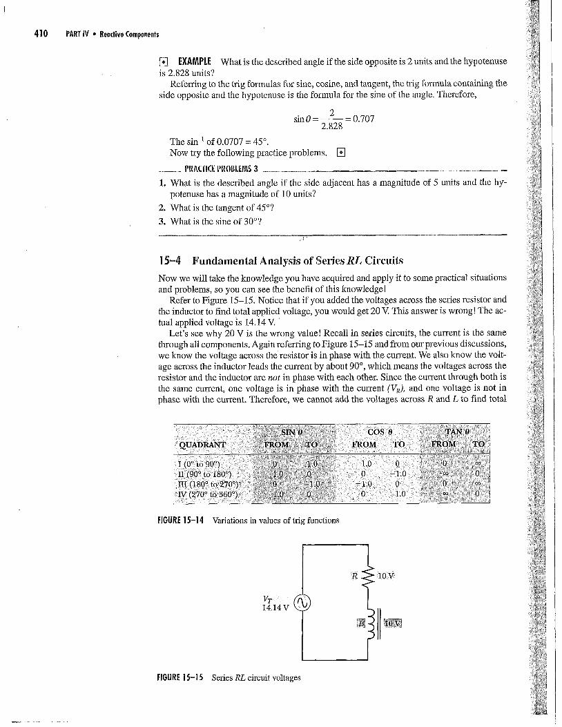
transformers16-5 Important transformer ratios16-6 Transformer losses16-7 Characteristics of selected transformers16-8 Troubleshooting hints
OBJECTIVES
After studying this chapter, you should be able to:
i. Define mutual inductance2. Calculate mutual inductance values3. Calculate coefficient of coupling values4. Calculate turns, voltage, current, and im-
pedance ratios5. List, draw, or explain physical, magnetic, electri-
cal, and schematic characteristics of varioustransformers
6. List common transformer color codes7. Define at least two types of core losses8. List common problems found in transformers9. List troubleshooting procedures
10. Use the computer to solve circuit problems
CHAPTER 16
439

PREVII:W
e stated earlier that one application of electromagnetic induction is the transformer. Fur-thermore, you know these devices have application in different frequency ranges and
for various purposes. That is, there are power transformers, audio transformers, and radio-frequency (rf) transformers, which all find various applications in many types of electroniccircuits and systems. Power supplies, audio amplifiers, radio and TV receivers, transmitters,and other systems and subsystems use the unique characteristics of these devices.
In this chapter, you will study the basic features and types of transformers that a tech-nician needs to understand. Practical information, such as schematic symbols and colorcodes, will be provided. Turns ratios, voltage ratios, current ratios, impedance ratios, andother major aspects about transformers will be studied. Finally, typical malfunctions andtroubleshooting techniques will be examined.
KEY TERMS
AutotransformerCoefficient of coupling (k)Copper lossCore loss
Current ratioImpedance ratioIsolation transformerMutual inductance (M or LM)
TransformersTurns ratio (TR)Voltage ratio
16-I Background Information
You know when a changing current passes through a conductor wire o1" a coil, an expandingor collapsing magnetic field is produced. This expanding or collapsing field, in turn, inducesa counter-emf (cemf). This process of producing voltage through a changing magnetic field isknown as electromagnetic induction. When the induced voltage is created across the cmTent-carrying conductor or coil itself, it is called self-induction. As you know, the symbol for thisself-inductance is L.
Another important kind of induction is mutual induction. The unit of mutual inductanceis the henry and the symbol is M. (NOTE: Sometimes you will also see the abbreviation LM.)
One definition for mutual inductance is the property of inducing voltage in one circuit byvarying the current in another circuit. Refer to Figure 16-1 and note that Coil A is connectedto an ac source. Coil B is not connected to any.source. However, it is located close to coil Aso that most of the flux produced in Coil A by current from the source cuts or "links" Coil B.Since a conductor, magnetic field, and relative motion will induce voltage, a voltage is in-duced in Coil B because of the changing current in Coil A. By definition, there must be mu-tual inductance. These two circuits (Coil A and Coil B) are positioned so that energy istransferred by magnetic linkage. This coupling between circuits is also sometimes called in-ductive coupling. Inductive coupling is due to flux linkages.
16-2 Coefficient of Coupling
. In Figure 16-2 you can see smaller and greater amounts of flux linkage between coils. A termexpressing this relationship by the fractional amount of total flux linking the two coils is
Source
A/ \B
LI
\ ',N-'|/ /h I'-ÿd i
\ /
( Voltmeter
FIGURE 16-1 Mutual induction by flux linkage

CHAPTER 16 " Basic Transformer Characteristics - 441
ii/ / /
(a) i Small amoÿi of flux linkage: lowi (b) i increased amount: laigtler i€oefficient of coupling (low k) i coefficient of coupling (high k)
FIGURE 16-2 Coefficient of coupling related to degree of flux linkage
Close proximity Greater distance Aligned windingsmeans more (less proximity) means morecoupling means less coupling
coupling
FIGURE 16-3 Factors influencing coefficient of coupling (k)
i Proximity! ,Reiative position} : Core material andhow it is wound
Perpendicularcoils havesmall amountof coupling
Windingson same ironcore havehigh degreeof coupling
Air core separatewindings have smallamount of coupling
coefficient of coupling, represented by the letter k. Coefficient of coupling and mutual in-ductance are not the same. However, they are related. Figure 16-2b shows the coils with thehigher coefficient of coupling. The coefficient of coupling is therefore computed as the frac-tionaI amount of the total flux linking the two circuits. When all the flux from one circuitlinks the other, coefficient of coupling (k) equals one. When two-thirds of the flux links theother circuit, k equals 0.66, and so forth.
See Figure 16-3 for examples of factors that influence the coefficient of coupling. These fac-tors include the proximity of coils (the closer they are the higher the k); the relative positionsof coils with respect to each other (parallel coils at a given distance have greater k than per-pendicular coils); and other factors, such as when the coils are wound on the same core. Coilswound on the same iron core have a coefficient of coupling almost equal to unity (1). Virtuallyall the flux produced by one coil links the other coil, with little leakage flux occurring. Air-corecoils (often used in rf circuits) have a k that indicates a percentage of coupling from less than5% (k = 0.05) to about 35% (k = 0.35). Obviously, air-core coils have more leakage flux.
[] IN-PROCESS LEARNING CHECK 1
Fill in the blanks as appropriate.
1. Producing voltage via a changing magnetic field is called electromagnetic __
2. Inducing voltage in one circuit by varying current in another circuit is called
3. The fractional amount of the total flux that links two circuits is called the __ ofcoupling, which is represented by the letter . When 100% of the flux links the twocircuits, the __ of coupling has a value of.
4. The closer the coils are, the __ the coupling factor produced. Compared with parallelcoils, perpendicular coils have a __ degree of coupling. []

442 PART IV * Reactive Cornpo,enls
16-3 Mutual Inductance and Transformer Action
As stated, when two circuits are coupled magnetically, they have mutual inductance. Suchis the case for transformers. Transformers are devices that transfer energy fi'om one circuitto another by electromagnetic induction (mutual induction). Typically, transformers havetheir primal7 and seconda17 windings wound on a single core.
Refer to Figure 16-4. Notice the winding connected to the source is the primary winding.The winding connected to the load is the secondary winding. Some transformers can havemore than one secondary winding. Also, observe the schematic symbol(s) used for varioustransformers.
PracticaH NotesMost transformers shift the phase of voltage by 180° from input to output due to theelectromagnetic induction process. That is, when the top of the primary winding is positive,the top of the secondary winding is negative, and vice versa. When it is desired to produce atransformer that does not shift the phase, the manufacturer can reverse the dh'ection the wireis wound on the iron core for one of the windings. In this case, the top of the secondary canbe positive at the same time the top of the pnmary is positive. As stated earlier, the "sensedots" are often used to communicate this information.
Another feature shown on some diagrams, Figure 16-4, are sense dots. Sense dots indi-cate the ends of the windings that have the same polarity at any given moment. Usually, whensense dots are not shown, there is 180° difference between the primary and secondary volt-age polarity.
Two circuits have a mutual inductance of 1 henry when a rate of current change of oneampere per second in the first circuit induces a voltage of one volt in the second circuit.
Basic transformer Multiple secondary windings Multiple taps
'Primary :! S econdaÿ j
Center tap Sense dots same polarity Sense dots opposite polarity
Aircore
Ironcore
Centerta
IJÿ ÿ ] MultipleFIGURE 16-4 Primary and secondary transformer windings
i

2-
CHAPTER 16 ° Basic Transformer Characteristics 443
Mutual inductance between windings is directly related to the inductance of each wind-ing and the coefficient of coupling. The formula is:
FORMULA 16-1 M = kÿfÿ1 X L2
where M = mutual inductance in henrysL1 = self-inductance of the primary and !-a = self-inductance of the secondary (for
transformers) where Ls are in henrys
[] EXAMPLE A transformer has a k of i (100% coupling of flux lines), and the primary andsecondary each have inductances of 3 H. The mutual inductance (M or LM) is computed asM= 1 3-,f3x3=la/9=l-ÿ=3 H. []
PRA(TI([ PROBL[MS 1What is the mutual inductance of a transformer where the coefficient of coupling is 0.95, theprimary inductance is 10 H, and the secondary inductance is 15 H?
] 6-4 Mutual Inductance between Coils Other Than Transformers
We have been discussing mutual inductance in transformers. How does mutual inductance(coupled inductance) affect the total inductance of coils other than transformers that are lo-cated where their fields can interact?
Series CoilsWhen two coils are connected in series so that their fields aid each other, total inductance iscalculated from the formula:
FORMULA 16-2 Lr = L1 + I-2 + 2M
where Lr = total inductance (H)LI = inductance of one coil (H)L2 = inductance of other coil (H)M--- mutual inductance (H)
When two coils are connected in series so their fields oppose each other, the folÿula becomes:
FORMULA 16-3 Lr = Lÿ + I4 - 2M
Therefore, the general formula for series inductors is:
FORMULA 16-4 Lr = L1 + I4 + 2M
[] EXAMPtE Two inductors are series connected so their fields aid one another. Inductor1 has an inductance of 8 H. Inductor 2 also has an inductance of 8 H. Their mutual induc-tance is 4 H. What is the total inductance of the circuit?
Lr=Lÿ +Lz+2M= 8 + 8 + 8 =24 H []
_ PIÿA(Ti(E P[ÿ0BLEÿS 2What is the total inductance of two series-connected 10-H inductors whose mutual induc-tance is 5 H and whose magnetic fields are opposing?

7
444 PART IV • Reactive Components
Parallel CoilsWhen two inductors are inparallel with theix fields aiding each other, the formula is:
FORMULA 16-5LT = 1 1
4:Lÿ +M L2 +M
When two inductors are in parallel with their fields opposing each other, the formula be-comes:
FORMULA 16-61
Lr= 1 1+
L1 - M L2 - M
PRAGICE PROBL[ÿIS 31. What is the total inductance of two parallel coils whose fields are aiding, if LI = 8 H,
La = 8 H, andM= 4 H?
2. What is the total inductance of two parallel coils whose fields are opposing, if Lÿ = 8 H,L2= 8 H, andM= 4 H?
Relationship of k and MThe coefficient of coupling and mutual inductance are related by the following formulas fork and M.
FORMULA 16-7M
k=a/ÿ x L2
Recall Formula 16-1 is M= kÿ!ÿ x L2. As you can see from these two formula, mutual in-ductance and coefficient of coupling are directly related.
16-5 Important Transformer Ratios
We will begin this section by making the following assumptions.
1. With no load connected to the secondary winding, the primary winding acts like a simpleinductor.
2. Current flowing in the primary depends on applied voltage and inductive reactance of theprimary.
VIp Xt,
3. The primary current produces a magnetic field that cuts both the primary and secondaryturns.
4. A cemf is produced in the primary.
5. A voltage is produced in each turn of the secondary, which tends to equal the voltage in-duced in each turn of the primary because of mutual inductance. This means when thereare equal turns on the secondary and the primary, their voltages are virtually equal.
Using these assumptions, let's look at the ratio between electrical output and input parame-ters under specified conditions. When 100% of the primary flux links the secondary winding

CHAPTER 16 . Basic Transformer Characteristics 445
(when k = 1), the ratio of the induced voltages (i.e., the ratio of primary voltage to the sec-ondary voltage) is the same as the ratio of turns on the primary compared with the turns onthe secondary. Thus,
V; Nÿ
Ys Ns
where Vp is primary induced voltage; Vs is secondary induced voltage; Np is the number ofturns on the primary winding; and Ns is the number of turns on the secondary winding.
Observe Figure 16-5 and notice how the terms step up and step down relate to transform-ers. When the secondary (output) voltage is higher than the primary (input) voltage, the trans-former is a step-up transformer. Conversely, when the secondary voltage is lower than theprimary voltage, the transformer is a step-down transformer.
Turns Ratio
You will often find the turns ratio (TR) of a transformer expressed in terms of the ratio ofprimary turns to secondary turns (Np/Ns). For example, when the primary has 250 turns andthe secondary has 1,000 turns, the turns ratio is:
Np 250- =1:4
Ns 1,000
NOTE: A number of texts also show the opposite approach (i.e., secondary-to-primary ra-tio). Either apptvach works as long as formulas are consistently set up using the same ap-proach. In any case, the technician should be careful in making transformer calculations! Beconsistent in the way you set up the various ratios. We will use both ratios to familiarize youwith both approaches.
Notice that in Figure 16-6a the turns ratio is shown for both approaches. Also, in Figure16-6b, the voltage ratio is shown for both approaches.
Voltage Ratio
As you learned with the ideal transformer, the voltage ratio has the same ratio as the turns ra-tio; again see Figure 16-6b. That is:
Vp NpFORMULA 16-8 -- = --Vs Ns
(
2 turnsprimary
'5'5(
8 turns 10 turnssecondary primary
2 turnssecondary
FIGURE 16-5 Step-up and siep-down transformers
i Step downlistep Up:

446 PART IV • Reactive Components
'ÿPrimary-to-secondary turns ratio = 1:41
Secondary-to-prhnary turns ratio = 4:11
Laminated core
\ 240 V Primary Mndingturns
(a)!Tur sra oi
FIGURE 16-6 Turns and voltage ratios
Flux/Primary Secondary
--------o
51o00t.-
"-------o
i
:ill,¸
+i 1+:+
Secondary winding150 turns
i Step-down jratio 2:1 (P-S)i
(b)!Voltage ratio
= vp Ns = VsNS Vs Np Vp300 240 150 a2015---0 = 12---6 OR 30---6 = 24---6
2=2 !=L1 1 2 2
[] EXAMPLE1. What is the primary-to-secondary turns ratio of a transformer having eight times as many
turns on the primary as on the secondary?
Np 8TR .... or 8:1Ns 1
2. What is the secondary voltage on a transformer having a (p-s) turns ratio of 1:14 if the ap-plied voltage is 20 V?
lip Np . 20 1- Ns Vs 14;Vÿ =20x14=280 V []vÿ
__ PRAUI(E PROBLEMS 41. What is the p-s turns ratio of an ideal transformer whose secondary voltage is 300 V when
100 V is connected to the primary?
2. What is the p-s turns ratio of an ideal transformer that steps up the input voltage six times?
3. What is the secondary voltage of an ideal transformer whose p-s turns ratio is 1:5 andwhose primary voltage is 50 V?
4. What is the voltage ratio of an ideal transformer whose p-s turns ratio is 4:1? Is this a step-up or a step-down transformer?

CHAPTER ]6 • Busic Transformer Characteristics 447
lip= IOOVZp= 0.4A
(j) Pp= 4ow
FIGURE 16-7 Current ratio ÿ-n)UltiSIM
/
Is=2APs= 40w
® ®0.4A 2A
_Np2 Vpi Voltage = stepped doxmi:Ip 7- Nsÿ-Vs] Current = stepped up i
Current Ratio
Up to now, our discussions have been about transformers with no load connected to the sec-ondary(ies). Notice in Figure 16-7 that when a load is connected to the secondary, currentflows through the load and the secondary. This current produces a magnetic field related tothe secondary current. The polarity produced by the secondary current cancels some of theprimary field. Hence, the cemf is reduced in the primary, which reduces the impedance ofthe primary to current flow. This reduced impedance causes primary current to increase. Theinteraction between the secondary and the primary is termed reflected impedance. In otherwords, the impedance reflected across the input or primary results from current in the out-put or secondary.
In Figure 16-7, the power available to the load from the transformer secondary must comefrom the source that supplies the primary, since a transformer does not create power, buttransfers power from the primary circuit to the secondary circuit. Transformers are not 100%efficient. Therefore, the power delivered to the primary by its source is slightly higher thanthe power delivered by the secondary to its load. Since transformers are highly efficient (gen-erally ranging from 90% to 98% efficient), Figure 16-7 has assumed 100% efficiency to il-lustrate this principle. Later in this chapter, we will look at some losses that prevent actual100% efficiency.
Also notice in Figure 16-7 that the power delivered to the load is 40 W, where Vs = 20 V,Rs = 10 FI, and Is = 2 A. The power delivered to the primary is 40 W, where Vj, = 100 V andIp = 0.4 A. This is a step-down transformer where the voltage has been stepped down fivetimes. That is,
Np = 5:1 and Vp = 5:1Ys
What about the current ratio? Observe that the current in the secondary is five timeshigher than the current in the primary. Using our primary-to-secondary principle, the currentratio is 1:5, or the inverse of the voltage ratio.
This makes sense, if we assume that the power in the secondary is the same as the powerin the primary. In other words, Vsls = VpIe. If voltage were decreased by five times, the cur-rent would have to be increased by five times so the V times I (or P) would be the same inboth primary and secondary.
(NOTE: Power supplied to the primary must equal power delivered to the secondaryplus the power lost.)
Now let's relate current ratio to the turns and voltage ratios. Thus,
Is Nÿ VÿIÿ Ns Vs
Note the inversion in the current ratio. Since quantities equaling the same thing are equal to eachother, we can list three useful equations from the preceding information.

448 PART IV * Reactive Components
FORMULA 16-9Np VÿNs Vs
FORMULA 16-10Np Is
Ns 1t,
FORMULA 16-11 Vp _ IsVs Ip
If you know any three of the quantities in any of these equations, you can solve for the un-known quantity, assuming 100% efficiency.
[] EXAMPLES1. A transformer has 250 turns on the primary, 1,000 turns on the secondary, and the primary
voltage is 120 V, What is the secondary voltage value?
Np Vÿ
Ns Vs250 120
1,o0o vs25ors = 12o,ooo
120,000vs-
250= 480 V
2. A transformer has a primary to secondary turns ratio of 5:1. What is the primary currentwhen the secondary load current is 0.5 A?
Nv = IsNs Ip
5 0,5
1 Ip5Ip =lx0.5
0.5Ip - -0.1 A
53. The primary-to-secondary current ratio of a transformer is 4:1, and the secondary voltage
is 60 V. What is the voltage on the primary?
Vp _ Is
Vs Ip
vÿ 160 4
4Vp =60xl
Vÿ 60 15 V []4
Impedance Ratio
The impedance ratio is related to the turns ratio, Figure 16-8. Also, since inductance andthus the inductive reactance of a coil, relates to the square of the turns, the impedance alsohas a similar relationship. A load of a given impedance connected to the transformer sec-

CHAPTER 16 . Basic Transformer Characteristics 449
Load
,ÿlliZ iÿ}, :jÿipÿ2] (Primary-to-secondary)Zp= 8 × (4)2 = 8 ×16 =128 gÿ
Source
[:ÿS- ÿiÿ-2ÿ (Secondary-to-primary)
FIGURE 16-8 Impedance ratio
ondary is transformed to a different value by what the source sees "looking into" the primary(unless the turns ratio is 1:1). In fact, for an ideal (zero loss) transformer, the impedance trans-formation (secondary-to-pfimmN) is proportional to the square of the secondary-to-primaryturns ratio. That is,
(+)2FORMULA 16-12 s ZsZÿ
where Zs ÿ- the impedance of the load connected to the secondaryZp = the impedance looking into the primary from source
Ns _ the secondary-to-primary turns ratioN+
Another way of thinking about impedance ratios and their relationship to turns ratios isto consider that impedance can be regarded as the ratio of V to/. That is Z = VII. For exam-ple, if we consider a step-up transformer that steps up voltage by two times, we understandthe current is "stepped down" by two times (or is one-half). Then our ratio of V/I has be-come 2V/0.5I, which translates to a ratio of 4. Thus, the impedance of the winding with thehigher turns is four times that of the winding with the lesser turns. Of course, the converseis true if the transformer is a step-down transformer. The winding with the lesser turnswould have half the voltage and twice the current; thus, the 0.5V/2Iratio would indicate thatthe winding with the lower number of turns has an impedance that is one-fourth that of thewinding with the greater number of turns. Therefore, we see again, that the impedance ra-tio is related to the square of the turns ratio.
[] [X/ffqiPLE When the Ns/Np (secondary-to-primary) turns ratio of a transformer is 1:4and the impedance connected to the secondary is 8 g), the primary impedance is relatedto the square of the turns ratio. Hence, Zp is 16 times Zs. That is Zp = 8 x 16 = 128 ÿ, Fig-ure 16-8. A practical formula expressing this in terms ofprimmy-to-secondaly turns ra-tio is:
Nv 12FORMULA 16-13 = []

450 PART IV • Reactive Components
[] EXAMPLE A transformer has a secondary-to-primary turns ratio of 0.5, and a load resis-tance of 2,000 ohms is connected to the seconda'y. What is the apparent primary impedance?
Since the secondary-to-primary turns ratio is 0.5, the secondary has half as many turns asthe primary, or the primary has twice as many turns as the secondary. Appropriately substi-tute in the formula:
Zp=Zs(NPI2
Zp =2,000 ÿX(2)2Zÿ, = 2,000 ÿ × 4 = 8,000 ÿ2 []
PllA(ll(fi PROBKNS 5In the prior example, suppose the turns ratio reverses. In other words, the secondary has twiceas many turns as the primay. What is the apparent pfima'y impedance?
These discussions indicate the primary impedance of a very efficient transformer (as it looksto the power source feeding the primary) is determined by the load connected to the secondaryand the turns ratio. Because this is true, transfoÿaners are often used to match impedances. Thatis, a transformer is used so that a secondary load of given value is transformed to the optimumimpedance value into which the primary source should be looking. (The source may be an am-plifier stage, another ac signal, or power source.) Therefore, a useful formula is:
FORMULA 16-14 N---Z-P=JZ-ÿsNs
where N--L = the requiredprimmy-to-secondaty turns ratioNsZp = the primary impedance desired (required)Z s = the impedance of the load connected to the secondary
[] EXAMPLE An amplifier requires a load of 1,000 ohms for best performance. The ampli-fier output is to be connected to a loudspeaker having an impedance of 10 ohms. What mustthe turns ratio (primary-to-secondaly) be for a transformer used for impedance matching?
Nÿ _ ZÿsÿNs
Np _ ./1,000 = la!fO0 = 10Nsÿ 10
This indicates the primary must have 10 times as many turns as the secondary. []
__ PR/KIIC[ PR011KIÿS 61. What is the primary-to-secondary impedance ratio of a transformer that has 1,000 turns
on its primary and 200 turns on its secondary?
2. What impedance would the primary source see looking into a transfoiÿer where the primary-to-secondary turns ratio is 16 and the load resistance connected to the secondary is 4 ÿ?
16-6 Transformer Losses
Because of energy losses, practical transformers do not meet all the criteria for the ideal,100% efficient devices we have been discussing. These transformer losses consist primarilyof two categories. One category is copper loss, caused by the I2R copper wire losses that
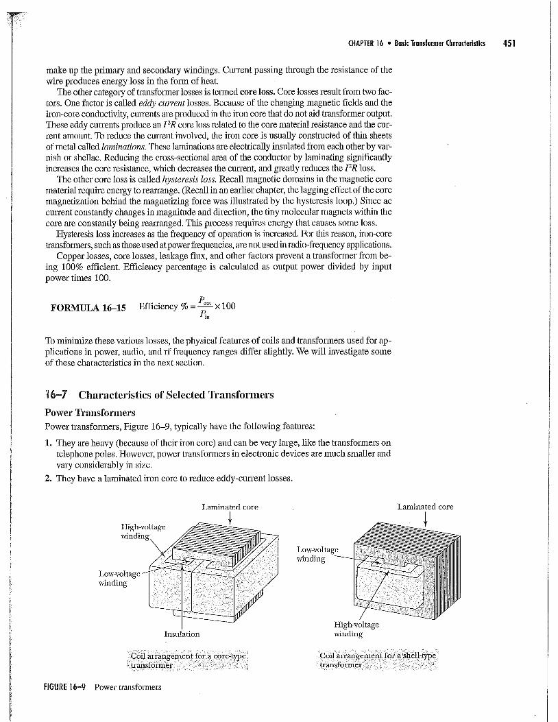
CHAPTER 16 . Basic Transformer Characteristics 451
make up the primary and secondary windings. Current passing through the resistance of thewire produces energy loss in the form of heat.
The other category of transformer losses is termed core loss. Core losses result from two fac-tors. One factor is called eddy current losses. Because of the changing magnetic fields and theiron-core conductivity, currents are produced in the iron core that do not aid transformer output.These eddy currents produce an I2R core loss related to the core material resistance and the cur-rent amount. To reduce the current involved, the iron core is usually constructed of thin sheetsof metal called laminations. These laminations are electrically insulated from each other by var-nish or shellac. Reducing the cross-sectional area of the conductor by laminating significantlyincreases the core resistance, which decreases the current, and greatly reduces the I2R loss.
The other core loss is called hysteresis loss. Recall magnetic domains in the magnetic corematerial require energy to rearrange. (Recall in an earlier chapter, the lagging effect of the coremagnetization behind the magnetizing force was illustrated by the hysteresis loop.) Since accurrent constantly changes in magnitude and direction, the tiny molecular magnets within thecore are constantly being rearranged. This process requires energy that causes some loss.
Hysteresis loss increases as the frequency of operation is increased. For this reason, iron-coretransformers, such as those used at power frequencies, are not used in radio-frequency applications.
Copper losses, core losses, leakage flux, and other factors prevent a transformer from be-ing 100% efficient. Efficiency percentage is calculated as output power divided by inputpower times 100.
FORMULA 16-15 Efficiency % = Pout x 100
To minimize these various losses, the physical features of coils and transformers used for ap-plications in power, audio, and rf frequency ranges differ slightly. We will investigate someof these characteristics in the next section.
] 6-7 Characteristics of Selected Transformers
Power Transforiners
Power transformers, Figure 16-9, typically have the following features:
1. They are heavy (because of their iron core) and can be very large, like the transformers ontelephone poles. However, power transformers in electronic devices are much smaller andvary considerably in size.
2. They have a laminated iron core to reduce eddy-current losses.
Laminated core
High-voltagewindingÿ
L.Cnÿ dlÿv°ÿtageÿ
Insulation
Laminated core
Low-voltagewinding
High-voltagewinding
Coil arrangement for a core-type;transformer
Coil arrangement for a shell-typetransformer
FIGURE 16-9 Power transformers

452 PART IV ° Reactive Components
3. The flux path is as short as possible to reduce leakage flux and minimize magnetizing en-ergy needed.
4. They use one of two core shapes--core type (primary and secondary windings on sepa-rate legs of the core) and shell type (both primary and secondary windings on the centerleg), again see Figure 16-9.
5. They have one or more primary and secondary windings.
6. They may have one tapped winding, such as the autotransformel; Figure 16-10. The au-totransformer is a special single-winding transfo:ÿer.
When the input source is connected from one end to the tap while the output is across thewhole coil, the voltage is stepped up. If the input voltage is applied across the whole coil andthe output taken from the tap to one end, the voltage is stepped down.
Variacs or Powerstats are trade names for autotransformers having a movable wiper-arm
tap that allows varying voltage from 0 V to the maximum level. They are often used as a vail-able ac source in experimental setups.
7. They isolate the circuitry connected to its secondary from the primary ac source (e.g.,the ac powerline). A 1:1 turns ratio transformer is specifically designed for isolation ap-plications, Figure 16-11. (NOTE: All standard transformers isolate secondary from pri-mary source regardless of turns ratios, except for autotransformers.)
acin
!acout
acin
=
" variableac out
Step downI
AutotransformerFIGURE 16-10
I a°lsource
Powercord
Input toisolation
transformer
Isolationtransformer
Knobfor settingvoltage out
ofvariac
Powerstator variac
variable-voltageautotransformer
FIGURE 16-11 Using an isolation transformer for safety when using a powerstat or variac-type variable voltage autotransformer

CHAPTER 16 . Basic Transformer Characteristics 453
When using this special 1:1 turns-ratio isolation transformer, the load on the secondaryhas no direct connection to the primary source. This provides a safety measure for peopleworking with the circuitry connected to the isolation transformer secondary.
8. They cannot operate at high frequency because of excessive losses that would be created.
9. Just two examples of the many color codes in use are shown in Figures 16-12a and b.
Safety HintsCaution: Bad shock can occur if no isolation transformer is used on the autotransformer inputside, because there is no isolation from the raw line voltage and ground connections in theautotransformer circuit. For this reason, do not use autotransforrners with a movable wiper-armtap unless you plug the autotransformer into an isolation transformer output, which isolates itfrom the raw ac power source. []
Practical NotesSome power transformers are used when it is necessary to be able to select either a 120- or240-V primary input source for the transformer. Therefore, there are transformers with twoprimary windings. These primary windings may be connected in series, when 240 V is thesource O.e., the end of one winding is connected to the beginning of the other winding, beingcareful to pay attention to phasing of the two windings). Alternatively, by connecting the twoprimaries in parallel (again being careful of phasing), the transformer primary can be fed froma 120-V source. By using these techniques, the secondary voltage output will be the samewith 120- or 240-V inputs, as appropriate.
Audio TransformersAudio transformers are similar to power transformers in their construction. They typically are:
1. smaller and lighter than most power transformers; and
2. unable to operate at frequencies above the audio range without excessive losses.
.------o Low-" voltage
"------O winding
High-======o voltage
- winding" (center-tapped)
-------o
LOW-voltagewinding
,' i!power transformer !Audio transformer!i
(a) (b)
FIGURE 16-12 Typical power and audio transformer color-coding systems

454 PART IV * Reactive Components
RF Transforlners and Coils
Because the flux is changing veiny rapidly, RF transformers or coils, Figures 16-13 and 16-14,have different features compared with power or audio transformers. Some features includethe following:
1. Cores are air core, or powdered iron core, depending on frequency and application. Air-core coils have virtually zero hysteresis or eddy-current losses. Powdered iron cores aremade by grinding metal matei'ials and nonconductive materials into granules, which arepressed into a cylindrical-shaped "slug." Each metal particle is therefore insulated, greatlyreducing losses such as eddy currents. See Figure 16-13a for examples of this coil.
Also, nonconductive ferrite materials can be used in RF coils or transformers. As you re-call, feÿTite materials are special magnetic materials that provide easy paths for magnetic flux
FIGURE 16-14 Example of an air-core RF coil
(a) (b)
fiGURE 16-13 Examples of various types of coils and cores: (a) powdered iron-core-type coils; (b) toroidal core
CHAPTER 16 * Basic Transformer Characteristics 455
but are nonconductive. Often, toroid-type cores are used in radio-frequency circuits andlower-frequency applications, Figure 16-13b.
2. RF coils and transformers typically have very low inductance values. Generally, these val-ues are in the microhenry or millihem'y ranges.
3. Figure 16-14 shows an example of an air-core coil found in transmitter applications.
Color Coding
Today, many power, audio, and RF transformers are designed and manufactured to be usedand mounted on printed circuit (PC) boards. Consequently, their connector terminals are de-signed for that technique. However, some transformers that have wire leads by which con-nection is made to the various windings are still available and in use. In that case, the leadsmay be color coded to identify the various windings and their connection points. Althoughthere may be variations from these, frequently the colors used include the following:
o Power tranffonners: Typically primary leads are black, high-voltage secondary is red, and ffcenter-tapped, the center-tap is red with yellow stripe; low-voltage windings may be yellow forone winding, green for another, brown for another and slate for another, depending on the num-ber of separate low-voltage windings the transformer has, and the type of circuitry involved.
o Audio transformers: Typically, one primary winding lead is blue and connects to the out-put electrode of the device feeding the transformer primary, the other end of the primarywinding is red, and connects to the circuit source; the secondary has one lead that is greenand feeds the input to the stage connected to the transformer secondary, the other secondarylead (return) is typically black.
, Radio fi'equency (RF) interstage transformers, such as intermediate-frequency (i.f.) trans-formers used in radio receivers, use colors similar to the audio transformers. That is, primaryleads are blue and red, and secondary leads are green and black.
Important Ratings to Consider When Replacing TransformersA listing of practical transformer ratings, which should be considered when replacing trans-formers, is shown below. Each of these parameters can be very important considerationswhen replacing a transformer.
Practical Transformer Ratings
i
POWER TRANSFORMERSInput volts
Output V,/, and kVA ratings
Insulation ratings
Size
Mounting dimensions
Weight
AUDIO TRANSFORMERSPrimary impedance
Secondary impedance
Maximum V, I, and P
Size
Mounting dimensions
16-8 Troubleshooting Hints
Transformer problems are virtually the same problems as those described in the chapter oninductance. Two basic problems are opens or shorts. The primary test to detect these defectsis the ohmmeter.
Safety HintsOnce again, we want to remind you that when checking large inductances (including transformerwindings) with an ohmmeter, take precautions not to get shocked by the "inductive kick" of thewinding's collapsing field when removing the ohmmeter leads from the winding under test.
[]

456 PART IV o Reactive Components
iopen windhl-g !
(a)
RÿO0
Short
R=0gÿ
Total winding shorted
(b)
FIGURE 16-15 Typicaltransformer troubles R
normal
I Il Short I' @ 'I ........ I
R=0gÿ
Rnormal R +normal
Short
I I
Low R
Rnormal
iWinding-to:core sbQrt)
(d)
Open Winding(s)With an open winding, the obvious result is zero secondary output voltage, even when sourcevoltage is applied to the primary. When the primary is not open and only one secondary of amultiple-secondary transformer is open, only the open winding shows zero output. To checkthese conditions, remove the power and use the ohmmeter.
Refer to Figure 16-15a to see an open winding. In this case, the ohmmeter registers an in-finite resistance reading, indicating the winding under test has an open. Both the primary andsecondary windings should be checked! Normal readings are the specified dc resistance val-ues for each winding.
Shorted Winding(s)Shorted turns or a shorted winding can cause a fuse in the primary circuit to blow (open) fromexcessive current. Another possible clue to this condition is if the transformer operates at ahotter than normal temperature. Also, another hint of shorted turns is lower-than-normal out-put voltage. Actually, partially shorted windings or windings with very low normal resistancesare hard to check when only using an ohmmeter. Therefore, watch for these clues when trou-bleshooting transformer problems.
However, the ohmmeter is useful to detect certain types of transformer short conditions. Fig-ure 16-15b shows a total-winding short condition. In this case, the ohmmeter reads virtually zeroohms when it should be reading the normal winding resistance value, if there were no short.
Figure 16-15c illustrates the condition when the primary and secondary windings areshorted together. In this case, each winding resistance might be normal; however, there wouldbe a low resistance reading between windings. When conditions are normal, "infinite ohms"is measured between primary and secondary windings.
Another possible short condition is when one or both windings are shorted to the metalcore, Figure 16-15d. Again, if things are normal, an infinite ohms reading will be present be-tween either winding and the core material.

CHAPTER 16 * Basic Transformer Characteristks 457
Light bulb
t llJl (No load connected) FIGURE 16-16 Onewaytofind shorted turns
NOTE: Use small bulb rating for small transformers;use larger bulb rating for large transformers.
*The requirements for bulb size and its electrical ratings are as follows:
1. The voltage rating should equal the same voltage rating as the transformer primary.
2. For small transformers, a small-wattage lamp should be used.
3. For large transformers, a large-wattage lamp should be used.
Be aware that choosing the correct bulb size and interpreting the results come only with ex-perience. This test is simply mentioned to show you some innovative ways technicians findout what they need to know, even in difficult situations.
PracticaB Notes*The following discussion describes one practical approach used to determine whether a short inapower transformer exists. This approach is a simple test involving the transformer in questionand a light bulb. In Figure 16-16, you can see a light bulb is placed in series with the transformerprimary winding. When a short is present in either the primary or secondary, the lamp glowsbrightly because of the higher-than-normal primary current. When no short exists, the lamp doesnot glow or may glow dimly.

458 PART IV • Reactive Components
Summaryo When the magnetic flux of two coils link and interact, nm-
tual inductance and inductive coupling occur between thetwo circuits.
° When mutual inductance is present, cun'ent changing inone circuit causes an induced voltage in the other circuit.The symbol for mutual inductance is M or LM, and the unitof measure is the henry.
o One henry of mutual inductance is present when a changeof 1 ampere per second in one circuit induces 1 volt in themutually coupled circuit.
• Expressing the fraction of total flux linking one circuit toanother circuit is called coefficient of coupling. The abbre-viation for coefficient of coupling is k. NOTE: Multiplyingk by 100 yields the percentage of total flux lines linking thecircuits.
° The relationship between mutual inductance and coeffi-cient of coupling is shown by the formulas:
• One key transformer parameter is the turns ratio. Turns ra-
tio is expressed either by the primary-to-secondary ratioNflNs, or secondary-to-primary ratio Ns/Np.
• The ratio of voltages between primary and secondary is thesame as the ratio of turns. That is,
Np Vÿ Nÿ Vs-- or -- = --N s Vs N p Vp
• The current ratio of a transformer is the inverse of the volt-age ratio. When voltage is stepped up from primary to sec-ondary, current is stepped down by a proportionate factor:
Vp Is Vs _ Ip-- 01"
Vÿ I ÿ, Y,, Is
M=k.,fÿ xL2 andk- M ,5/-ÿi × L2
where M = mutual inductance in henrys
k = coefficient of coupling
L1 = self-inductance of coil or transformerwinding 1
L2 = self-inductance of coil or transformerwinding 2
• Mutual inductance can exist between coils that are nottransformer windings but that are close enough for fluxlinkage to occur. This can affect total inductance for thecircuit.
• Transformers are composed of separate coils or windings,having inductive coupling. The primary winding is con-nected to an ac som'ce. The load(s) are connected to thesecondary winding(s).
• One feature of a two-winding transformer is that the pri-mary and secondary are magnetically coupled, yet electri-cally isolated from each other. This feature can keepcircuits and loads from being directly connected to thepower lines, which increases safety.
• The impedance ratio of a transformer is related to thesquare of the turns ratio. That is,
z__e_, =
Zs Ns2
When a transformer has 100% efficiency, the power deliv-ered to the load by the secondary equals the power suppliedto the primary by the ac source. The efficiency of iron-coretransformers is usually in the 90% to 98% range.
Two categories of transformer losses are copper losses andcore losses. Copper losses relate to the !ÿR losses of thecopper wire in the primary and secondary windings. Corelosses result from eddy currents being induced in the coreby the changing magnetic flux, and the energy wasted dueto hysteresis losses. Eddy currents in the core materialcause 12R losses.
• Transformers have various applications at different fre-quencies. Three transformer categories include powertransformers, audio transformers, and RF transformers.
• Power and audio transformers generally have laminated ironcores, for efficiency's sake. RF transformers usually use aircores, special powdered iron, or ferrite in their core material.
• Transformers can develop abnormal operations because ofopens or shorts. Opens are evident by lack of output. Shortsbetween rams, from winding-to-winding or from winding-to-core, can be seen by overheating, blown fuses, and so forth.

CHAPTER 16 . Basic Transformer Characteristics 459
Formulas and Sample Calculator Sequences
Formula 16-1(To find the vahteof mutualinductance)
M = kÿfÿl X L2
k value, [}ÿ], IT], L1 value, N,/4 value, [ÿ, [ÿ], []
Formula 16-2(To find the valueof tota! inductancefor two-seriesinductors havingaiding fields)
Lr=LI+/4 + 2M
L1 value, [¥],/4 value, [+], 2, N], M value, []
Formula 16-3(To find the valueof total inductancefor two-seriesinductors havingopposing fields)
Lr=L1 +/4- 2M
L1 value, [],/4 value, E], 2, [], M value, []
Formula 16-4(The general formulafor total inductance oftwo inductors havinginteracting fields)
Lzr = Lÿ +/4- 2M
L1 value, [¥],/4 value, [] or [] as appropriate, 2, N], M value, []
Formula 16-5(To find the totalinductance of twoparallel inductorshaving aiding fields)
1Lr= 1 1
+Lÿ +M L2 +M
/4 value, [], M value, [], ffÿ], [], IT],/4 value, E], M value, [3q, [ÿ, [], ff72
Formula 16-6(To find the totalinductance of nvoparallel inductorshaving opposingfields)
1Lr= 1 1
+L1 - M L2 - M
LI value, [-2], m value, [ÿ], [ÿ1, E], IT],/4 value, [], m value, El, [ÿ, [], [ÿ
MFormula 16-7 k =(To find the coefficient ÿ]L1 ×L2
of coupling between M value, [}], [T], L1 value, ÿ,/4 value, E], [ÿ], []two inductors)
Formula 16-8(To show therelationship of thevoltage ratio of atransformer to itsturns ratio)
Vp = Np
Vs Ns
Vÿ value, t-+-I, Vs value, [ÿ], (should equal) Np value, [-47, Ns value, []

460 PART IV • Reactive Components
Formula 16-9 N__y._p = V,,,
(To show the Ns Vsrelationship of thetarns ratio of a Nv value, [ÿ, Ns value, [] (should equal) Vp value, El, Vs value, []
transformer to itsvoltage ratio)
Formula 16-10(To show therelationship of thettl171s ratio of atransfolTner to itscurrent ratio)
Np Is
Ns Ip
Nt, value, I-+], Ns value, [] (should equal) Is value, IT], Ie value, []
Vp= I_LsFormula 16-11(To show the Vs Iprelationship of the Vp value, [], Vs value, [] (should equal) Is value, IT], lt, value, []voltage ratio of atransformer to itscurrent ratio)
Formula 16-12(To show therelationship of the
. turns ratio of atransfornzer to itshnpedance ratio)
Ns )2 Zsj : z-7
Ns value, ÿ, Np value, [], I-x-q, [] (should equal) Zs value, E], Zÿ value, []
Formula 16-13(To find apparentprimaly impedance ofa transfolwzer with aknown secondaryload hnpedance, whenthe transformer tulTlsratio is known)
Ze =Zs(NP ]2
Zs value, ÿ, [ÿ, Ne value, [-$], Ns value, E], [ÿ, []
Formula 16-14(To find the neededtransformer turnsratio to match givenimpedance conditions)
N.__.LP = Zÿs
NsNp value, ÿ, Ns value, [] (should equal), [-ÿ, Zp value, [+], Zs value, [], []
Formula 16-15(To find transformerefficiency)
Efficiency % = Pout × 100
Pout value, I-ÿ, Pi, value, [-x-I, 100, []
EXCEL AUTOMATED FORMULASHelpful problem-solving tools, such as the Excel automated formulas available on the CD, allow automaticcalculations of formulas.

CHAPTER 16 * Basic Transformer Characteristics 461
Using ExcelBasic TransformerCharacteristics Formulas(Excel file reference: FOE1601.xts)
DON'T FORGET! It is not neces-saJy to retype formulas once theyare entered on the worksheet! Justinput new parameters data for eachnew problem using that formula, asneeded.
Use the Formula 16-13spreadsheet sample and solvefor the value of primary im-pedance, assuming that theparameters are those calledfor in Practice Problems 5.Check your answer out againstthe answer given in the Appen-dix for this problem.
!;1: A I ! D E I F t G ! H I :ÿ I :ÿt;j.o.m,,,.,.-1.: z. = z,. (.¢N.ÿ' t J I I Iÿ! i---]
F27(Us ng parameter values given in Example under Formula 16-13 in text) " " [ _ : [zÿ-dh-dÿi--N-p .... ÿ ........ i-ip-Cÿ;!-ÿ=- Colu-ÿ-ÿ-ÿdÿ--to--dÿ--I ............. -i ......... ÿ I
Ii : : ........... ÿ .......... L__ ÿ ...... L ....... I .......... ISII............................. ÿ --: : I { I -
............................ : I i { ..... : ................
! .......... j .......... ÿ .... : ....... I ........................ I .................... :_.__I..7 ........... I " ] : I I ,
Iÿ .............. i ......... I ..... _ ................... L_
:14 ............ ' ..........................I ÿ ............ i .............. " .......... : ..................... i ....... I
....... I -I i ! ! .......... i ........ i ...............
il ÿ* [] ÿ "{i:ÿiÿ;-';;ÿwo;ÿ ....... ]irÿM,o,ooo. ÿ,o., jÿÿ ÿ PMÿ:!
Again, use the Formula 16-13spreadsheet sample and thesame turns ratio as used in theproblem above. What wouldthe primary impedance valuebe if the secondary load were16 ohms?

462 PART IV * Reactive Components
Review Questions1. When current changing in one circuit causes induced
voltage in another, it is called:
a. transformation.
b. mutual inductance.
e. decoupling.
d. flux leakage.
2. When a change of 1 A per second in one circuit induces1 V in another circuit:
a. there is no mutual inductance present.
b. there is 1 henry of mutual inductance present.
c. the coefficient of coupling is unity.
d. there must be a transformer involved.
3. Coefficient of coupling expresses:
a. a relationship to flux density and magnetizing force.
b. a fractional value of the total flux linking one circuitto another.
c. a percentage.
d. none of the above.
4. In a transformer:
a. the secondary is connected to the source.
b. the secondary is always connected to a load.
c° the primary is connected to the source,
d. none of the above.
5. In a transfotTner:
a. the primary and secondary are electrically connectedto each other.
b. the primary and secondary are only magnetically cou-pled.
c. the primary and secondary are both electrically andmagnetically coupled.
d. none of the above.
6. Turn ratios for transformers may be expressed:
a. only as a ratio of primary turns-to-secondary turns.
b. only as a ratio of secondary turns-to-primary turns.
e. either as primary-to-secondary or secondary-to-
primary ratios.
d. none of the above.
7. The voltage ratio of a transformer:
a. is equal to the turns ratio,
b. is not equal to the turns ratio.
c. has no relationship to the turns ratio.
d. none of the above,
8. The cmTent ratio of a transformer:
a. is directly related to the voltage ratio.
b. is inversely related to the voltage ratio,
c. is not related to the voltage ratio.
d. none of the above.
9. The impedance ratio of a transformer is equal to:
a. the voltage ratio.
b. the cm:rent ratio.
c. the square of the turns ratio.
d. none of the above.
10. The typical efficiency of iron-core transformers is ap-proximately:
a. 10% to 20%,
b. 80% to 88%.
c. 90% to 98%.
d. none of the above.
11. Copper losses in a transformer come from:
a. resistance of the iron in the core material.
b. eddy currents.
e. resistance of the wire in the windings.
d. none of the above.
12. Core losses in a transformer may come from:
a. hysteresis and eddy currents.
b. winding losses and metal core losses.
c. leakage flux alone.
d. all of the above.
13. Iron cores are typically laminated, rather than solid:
a. to decrease their resistance to current,
b. to increase their resistance to current.
c. to make the cores lighter in weight.
d. none of the above,

CHAPTER 16 . Basic Transformer Characteristics 463
14.
15.
C.
d.
16. A
a,
b.
C.
d.
Iron cores are usually used for:
a. audio and RF transformers.
b. power and RF transformers.
c. power and audio transformers.
d. power and large RF transformers.
The most common problems in transformers are:
a. shorted turns and lamination buzz.
b. shorted turns and overheating.
opens and shorts.
opens between windings and core.
blown fuse in a transformer circuit may indicate:
an open transformer winding.
a short between windings.
an open in a single winding.
none of the above.
17. A lack of output from a transformer may indicate:
a. a low resistance.
b. an open.
c. excessive leakage flux.
d. none of the above.
18. The ohmmeter can be used to find transformer trou-bles, such as:
a. open windings.
b. shorts between windings.
c. shorts between core and windings.
d. all of the above.
Problems1. What is the primary current of a transformer whose
source is 120 V and secondary is supplying 240 V at100 mA?
2. What is the secondary voltage of a transformer having asecondary-to-primary turns ratio of 5.5:1, if the sourcevoltage is 100 V?
3. What is the primary-to-secondary turns ratio of a trans-former whose primary voltage is 120 V and secondaryvoltage is 6 V?
4. If a transformer has a primary-to-secondary turns ratioof 5:1 and the load resistance connected to the sec-ondary is 8 ÿ, what impedance is seen looking into theprimary?
5. What is the mutual inductance of two coils having acoefficient of coupling of 0.6, if each coil has a self-inductance of 2 H?
6. What is the total inductance of two coils in series having a0.3 k, if each of the coils has a self-inductance of 10 mH?(Assume their fields are aiding.)
7. What is the total inductance of two coils in parallel hav-ing a 0.5 k, if each coil has a self-inductance of10 H. (Assume their fields are opposing.)
8. What is the secondary voltage of an ideal transformerwhose secondary-to-primary turns ratio is 15 and pri-mary voltage is 12 V?
9. How many volts per turn are in a transformer having a500-turn primary and a 100-turn secondary, if the pri-mary voltage is 50 V?
10. A 6:1 step-down transformer has a secondary current of0.1 A. Assuming an ideal transformer, what is the pri-mary current?
11. What is the number of turns in the primary winding ofthe transformer shown in Figure 16-177
12. Assuming an ideal transformer, what is the power deliv-ered to RL in Figure 16-187
l f°°Iturns 25 11I=3A
FIGURE 16-17
100 V RL10 kfÿ
FIGURE 16-18

464 PART IV ÿ, Reactive Components
13. What is the primary-to-secondary turns ratio in Figure16-197
14. What is the primary cmÿent in the transformer circuit inFigure 16-207 (Assume an ideal transformer.)
15. What is the voltage applied to the primary of the circuitin Figure 16-217
120 V jÿ 300 t -ÿ
FIGURE 16-20
V285 V
FIGURE 16-19 FIGURE 16-21
60 V
400 t t 40 kgÿ
Analysis Questions1. Research the termflyback transformer. Indicate where it
is used, and whether its output is a high or low voltage.Also, list the frequency at which a TV flyback trans-former is operating.
2. Why are the cores of transformers laminated iron ratherthan solid iron?
3. An amplifier having an output impedance of 5,000 ÿ2 isfeeding its output signal to a matching transformer. If thespeaker connected to the secondary is a 16-ÿ speakerand the number of turns on the secondary is 200 turns,what number of turns should the primary winding haveto provide the best impedance match? (Assume a perfecttransformer.)
4. The primary-to-secondary turns ratio of a transformer is8:1. What is the primary current, if the power delivered toa 200-ÿ load resistance is 405 mW?
,
6,
If the impedance ratio (primary-to-secondary) of an idealtransformer is 36:1 and the number of turns on the pri-mary is 1,200, how many turns are on the secondarywinding?A TV receiver contains a transformer in its power sup-ply. If you unplug the receiver from its 120-V, 60-Hz wallplug (ac source), turn the on/off switch to the on position,and connect an ohmmeter to each lead of the ac cord'splug, the ohmmeter reads 10 ÿ2. Using Ohm's law, youthink the current supplied to the transformer is 12 A, sinceI = V/R, or 120 V/10 ÿ. Explain why the circuit is fusedwith only a 5-A fuse, yet, when the TV receiver is turnedon, the fuse does not blow!
Fl'
Chapter TopicMutual Inductance and Transformer Action
Important Transformer Ratios
Performance Projects Correlation ChartSuggested performance projects in the Laboratory Manual that correlate with topics in this chapter are:
Performance Project
Turns, Voltage, and Current Ratios
Turns Ratio(s) versus Impedance Ratios
Story Behind the Numbers:Basic Transformer Characteristics
Project Number4546
NOTE: It is suggested that after completing the above projects, the student should be required to answer the questions in the "Summary" at the end ofthis section of projects in the Laboratory Manual.