Embed Size (px)
Citation preview

ILtOANGERI
ILtCAUTION]
ILt~~
ILt~~
bull Never adiust the knobs on the controller unit while driving as it is extremely dangerous
bull Never disassemble this product bull If any unusual engine characteristics arise during use of this unit
discontinue use immediately and contact our office bull Read this instruction lII8llual carefully before installation and
proceed setting after you obtain full inforll8tion of this unit and manual
bull If this unit is stalled erroneouslY the vehicle and its related equipement will be dwaaged
bull Manufacturer is not responsible to the vehicle and its related equipments damaged due to erroneous wiringS Also manuafacturer is out of responsibility for any damage andor aCCident if this unit is equiped and set with vehicle not specified on this lII8llusl
bull Be sure to complete necessary points on Application Form of Inspection and Repair when the unit need an inspection anltior repair APPlY the inspection andor repair to the dealers It takes longer time for inspection andor repair if the Application form is not attachelti
RJiWEXn APEX CO Ltd JAPAN
SUPER
bull SUPER ACTUATOR VALVE CONTROLLER TVPE-R
INSTRUCTION MANUAL
c=J[=J[=JcJcJc=J-A O B Ll c===- _-=J-I 0 D L-sEipoundcr---J L7 MODE UPII
IIi f 0 cJ~-- Ov SUPER ACTUATOR VALVE CONTROllER TYPE-R czgtAl1iXll
1LgtJUgtEXii
f I Introduction 2 I Warnings 3 Parts List 4 Part Names 5 Product Main Features 6 Installation Procedures [I Fundamental Piping I Actuator Type 2 Waste Gate Type [2 Wiring Unit Mounting
1 I 2 2 3 3 3 3 4 5
I Electrical Signal -Iarness Connection 5 2 Coupler Harness Connection 6 3 Main Connection Diagram 6 7 Product Functions 7 L Control Unit 7 2 Boost Pressure Regulating Solenoid Valve 3 Pressure Sensor 7
8 Operational Instructions 7 (l] Set Up Mode 7 I Engine Type Setting 8 2 Preset Boost Pressure Setting 8 3 Preset Boost Duty Setting 9 3-1 Actuator Type 9 3-2 Wastegate Type 10 4 Set Up Lock Function II [2] Monitor Mode 12 I Boost Pressure Display FUllction 12 2 Injector Pulse Display Function 12
7
Table ofContents
9 Vehicle Specific Installation Table L TOYOTA 13 2 NISSAN 14 3 MITSUBISHI 15 4 MAZDA 15 5 SUBARU 15 10 Vehicle Specific Computer Location Diagram 16 II Vehicle Specific Computer Wiring Diagram 17 I TOYOTA 17 2 NISSAN 18 3 MITSUBlSHI 18 4 MAZDA 19 5 SUBARU 19
bull Actuator Type Vehicle Specific Piping Diagram 20 I Vehicles With Boost Pressure Regulating 20 Solenoid Valve - I 2 Vehicles With Boost Pressure RegUlating 21 Solenoid Valve - 2 3 JZA 80 JZS 147 Specific Piping Diagram 22 4FD3S Specific Piping Diagram 23 5 BD5 BG5 Specific Piping Diagram 24
1 SUPER AVC-R
Super Actuator Valve Controller Type - R
1 lulroductioll Thank you for purcliasing the APEXi Super A VC-R This is a highly efficient boost
controUer excelling in rapid boost response and stability This unit can be installed on virtually any turbo vehicle ranging from nomlal engines to hard tuned engines with its self-learning function Furthermore the standard real time boost pressure display and real time injector pulse display have been included in this unit Please be sure to read this manual completely and use the ullit properly
2 WARNlNGS - Please be sure 10 readshybull Although this unit may be installed on virtually any turbo vehicle ranging from normal modified engines to turbo upgrades the unit utilizes the injector signal for its self learning function which limits its usage to Electronically Controlled Fuel Injection System Vehicles Running On Gasoline Please be aware that the Self- Learning mode cannot have an accurate reading irthe injector pulse display does not work and if the installation vehicle has an electrical current controller for the injector signal (For instance IZ 3 1 It 31 )
This unit may be programmed up to a maximum boost pressure of20 ( kglcm2) Raising the boost pressure above normal settings which exceeds the vehicles fuel supply margin lIIay lead to engine failure When raising boost pressure please raise the boost according to the margins of the injector air flow meter and fuel pump ofthe engine and turbo
bull Please be warned that our tompally is 1I0t respollsible for ANY damages incurred to the engine turbo alld all Ielated cOlllllOllents due to IInnecessary alld excessive boost presllJre levels bull
Some vehicles may have a fuel cut system when the boost pressure has been raised Please release the fuel cut system in these cases Please contact our company if there are lIny problems releasing the fuel cut system
bull Please use extra caution when proceeding with wiring or pilling procedures ollimiddot cOlllpany is 1101 responsible for any vehicle trouble resulting from falllty blstallaHoll
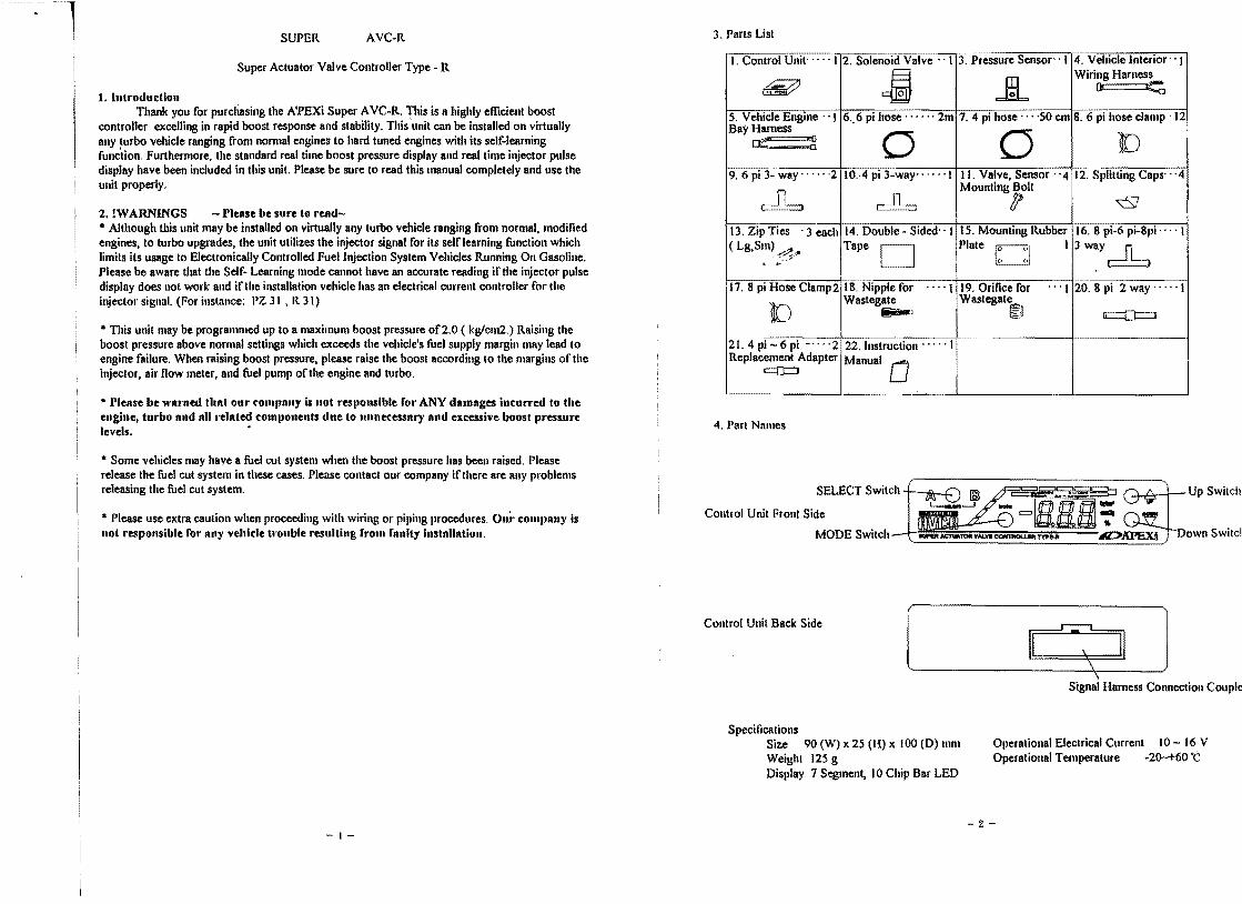
3 Parts List
I Control Unitmiddot I 4 Vehicle Interior I Wiring Harness
3 Pressure Sensor- 1 2 SolenoiifValve - I
~ [ll ~HL 86 pi hose clamp 12
Bay Harness 5 Vehicle Engine 1 6 6 pi hosemiddotmiddotmiddotmiddotmiddotmiddot 2m 74 pi hose middot50 cm
[)Cf----ii 0 0 9 6 pi 3- way middot2 10fpi 3-way- - 1 II Valve Sensor -4 12 Splitting Caps-
Moullting Bolt ltSJ
16 8pi-6 pi-Spi - _ I ( LgSIII) ~
IS Mounting Rubber13 Zip Ties 3 each 14 Double - Sided 1 PlateTape 13Wlly~
20 8 pi 2 way I Wastegate 18 Nipple for 17 8 pi Hose Clamp2 19 Orifice for
Wastegate[) ~l ~l oJ=J
214pi-6pi -middotmiddotmiddotmiddot2 22 Instruction Replacement Adapter Manual 0
c(Jl
4 ParI Names
SELECT Switchc II t fiIl ~ Jlsect5J I 1 Up Switch
Control Unit Front Side ~ 1ICIIotloltyend --~-- bullbull - Down Switci-t
MODE Switch
Control Unit Back Side [ GJ] Signal Harness Connection Couple
Specifications Size 90 (W) x 25 (H) x 100 (D) mill Ollerational Electrical Current 10 - 16 V Weight 125 g Operational Temperature -20-+60C Display 7 Segment 10 Chip Bar LED
-2shy1shy
-1 5 Froduct Main Features Boost response is extremely fast Excels in stabilizing boost levels ( Especially in higher RPMs) 2 Mode boost preset function Self -learning function maximizes use of a highly efficient CPU Achieves a level of perfect management of RPM specific boost management by combining the injector signal with the RPM signal Applies the best suited boost control even under high RPM levels Utilizes a wide- range absolute pressure sensor which accommodates high boost settings and changes in the air pressure Includes a high precision real time boost display and injector pulse display along with a digital and bar graph display (Includes a maximum injector pulse indicator) For extra safety a preset boost locking feature is included (set-up) Easy to mount 14 DIN case size
6 Inslnilation Frocedures Cautioll Please be sure that the engine has fully cooled down before attempting any piping installation Please be sure to disconnect the negative terminal of the battery before attempting any wiring installation Please mount this unit away from direct sunlight Please mount this unit where the driver cannot reach ( Approximately SO cm away from the drivers seal)
LIJ Fundnmentnl Filling I Actuator TYlle 1 Discollnectthe hose from the turbine compressor to the actuator 2 Cut the necessary length of6 pi hose and connect the compressor side to the NO side of the solenoid valve and the actuator side to the COM side of the valve as shown in the diagralll (Leave the NC side of the valve open) 3 Mount the solenoid valve away rrolll high telllllelllture areas with the included bolts and Rubber Mounting Flate Cantion Installing the solenoid valve near high temperature areas or monnting the valve withont the I1Ibber mOllnting Idate lIIay sholten the life span or the valve and in the wont cnses break the valve 4 Locate the hose frOI1l the surge tank to the fuel pressure regulator and insert the 4 pi 3 way into the 4 pi hose Connect another 4 pi hose to the open side cut an appropriate length and connect it to the pressure sensor 5 Mount the pressure sensor nwny flolll high tempernture nreas and use the included bolts to Illount the sensor with the connected hose facing downwards
-3shy
Cantion Installing the IIIesslIle senSUI neal high tellllelatUle aleas lIIay affect the accuracy or the sensol aud in the WOlSt cases blenl the SenSOI
6 Secure all hose connections with either a hose clamp or n zip tie and make sure that none of the hoses are crimped
NC to Atmosplu
~ nnecttoNO fi S-AVCR
Solenoid Valve
Actuator Type Piping Diagram Boost Controller Kit Piping Diagram
COM Connection NC to Atl1losph
13shy
Pressure Sensor Piping Diagram Twin Turbo Piping Diagram
Vehicles with boost pressure regulating solenoid valves and other vehicles which require special piping examples have been listed in the back or this manual
2 Wastegate Type ( Poppet Type) I Connect the included 6 pi wastegate nipple to the top nipple of the wastegate ( llease allilly sOllie sealing agent onto the tllleaded Ilart of the nipple) 2 Disconnect the nipple connected to the NO of the solenoid valve and connect it to the NC side of the solenoid valve ( Ilease nIY SOllie sealing agent OlltO the thleaded part ur the lIiIle) 3 Attach the included orifice to the open NO side ofthe solenoid valve 4 Connect the included 8 pi - 6 pi - 8 pi 3 -way in between the hose coming froll the surge tank to the lower side of tile w8stegate Cut and connect a 6 pi hose to the open side orthe 3 way and connect it to the NC side of the solenoid valve ( The NO side or the valve is open to the atmosphere ) COllnect a 6 pi hose to the nipple froll step I and hose it to the COM side orthe solenoid valve S Please rerer to steps 3 - 6 from the actuator type instructions
4shy
--1
frolll exhast wastegale connect an orifice to the NO side l1Ialllfold 16 pi nipple ( atmosphere) connect to COM1 ~ 1 ~S-AVCR
solenoid valve
J-t I 8-6-8 pi 3 way 4 connect to NC
compressor 8 pi hose turbine 6 pi hose
Wastegate type S-A VCR Piping Diagram
Caution ( Same for Actuator I Wastegate type) bull Some vehicles may come equipped with a boost pressure regulating solenoid valve lIe8se disconnect the hose frolll this unit and cap the unit olTwhen installing the S-AVCR ( Fallule to disconllect this solenoid valve lIIay calise extreme boost incrense) bull Crimps in the hoses lIIay cause the boost not to rise or in some cases the boost to rise too much) Some boost meters may include an orifice in their 3 -ways This unit will not operate correctly with those 3 ways Please keep all other piping separate from this unit 12) Wiring Unit Mounting 1 Elechmiddoticnll Sigllal lIamess Connection 1 Please disconnect the negative terminal of the battery (lease nole all radio and clock settings 011 a sheet of paper as Ihey may be erased when the terminal is disconnected 2 Please locate tlul vehicle engine control unit (Please refer to the Vehicle Specific Compuler Location Diagram) 3 While referring to the Vehicle Specific Computer Wiring Diagram use the included Harness Splitting Caps to connect the 1lead wires off of the Vehicle Interior Wiring Harness to the appropriate wires on the vehicle computer I Connect the orange lead wire to the constant power wire II Connect the red lead wire to the IG power wire III Connect the black wire to the ground wire IV Connect the blue wire to the injector signal wire ( Please be sure to connect these wires to the vehicle side of the harness when using subshycomputers such as the F MANAGE) I Cautioll The self learning lIIode of this boost controller will not ollernte alld prollel boost cOlltnl call1lot be achieved ulliess the injector sigllal wire is cOllnected Jlease be 5111e to connect the injector signnl wiJoe 4 Please be sure to cover all connections using the splitting caps with electrical tape
-5shy
2 Coupler llarness COllnection I Connect the 8 pin coupler (white) of the Vehicle Interior Wiring Harness to the control unit 2 Locate a hole suitable to run the 6 pin coupler of the Vehicle Engine Bay Wiring Harness into the vehicle interior Ifno suitable hole is found please drill a suitable hole (Be sure not to damage allY other existing wires or hoses when opening the hole) 3 Connect the 2 pin coupler of the Vehicle Engine Bay Wiring Harness to the 2 pill coupler of the Solenoid Valve and connect the other 3 pin coupler of the Vehicle Engine Bay Wiring Harness to the 3 pin coupler ofPressure Sensor 4 Connect the 6 pin coupler from step 2 and connect it to the 6 pin coupler of the Vehicle Interior Wiring Harness 5 Please secure all wiring with zip ties once the mounting location for the control unit and solenoid valve have been found 6 Use the double - sided tape to mount the control unit and be sure to wipe 01T any excess oil from the mounting surface ICaution be sure to monllt the nnit in II position which does IIOt illterrere with driving opelatioll Avoid mounting the unit nnder directmiddot sunlight alld beating ducts 7 After checking for proper wiring and piping connections reconnect the negative terluina of the battery to complete the installation process
3 Main COllnection Diagram
Vehicle Interior I Engine Room
~ 2 pili coupler solenoid valv
f~pressure senso
3 pin coupler
~~PI~ Super AVC-R control unit
-6
middot---1 I 7Plodnct FUlIction
1 Control U uit
Setup Mode Engine Type Setting ( Piston or Rotary)
Preset Boost Pressure Setting ( AlB 2 Memory)
L Preset Boost Duty Setting
Set Up locking Setting ( Personal Code Entry)
Boost Pressure Display Real Time Bar GraphMooo Mod L Injector Pulse Display Real Time Digital Display
2 Boost Pressure Regulating Solenoid This component receives its signal from the control unit and operates the valve either ON
OFF for a specified amount of time By managing and changing this ONOFF cycle (duty) in real time and monitoring the feedback information the unit is able to commence proper boost control The boost levels will proportionally become higher as the ON duration continues
3 Pressule Sensor The lInit lIIolli~ors the intnke nUlllilbld presslIc nlld uses this feedback to manage the
boost pressure and real time boost display Because this sensor is an absolute pressure sensor the sensor corrects its boost pressure
according to the existing outside atmosphere pressure The needle orsome boost meters may not read the specified boost levels at all times because the meters read off of relative boost pressure while this pressure sensor works off of absolute pressure
The needle ofsome boost meters may read higher than usual in areas of low atmospheric pressure and read lower in areas of higher atlllosphetic pressure
8 OpellltiollalinstlUctions 111 Set Up Mode Cantion Be silre that the nllit is properly set for the sllecified vehicle when installing for the fint time whell any of the COllllectolS have been disconnected 01 when the bnttel1 tenllinnl hlls been disconnected Failure to pIopel1y set the unit for the specified al1llliclltion nlllY lead to iUllllopel IIlIit operatioll and IIIlly lead to sedolls engille dllmage 111 the event that the vehicle slistains llllY damage our company willllsslllllc 110 responsibility
-7shy
1 Engine TYlle Selling Although this unit has a RPM separate selfleaming function it is necessary to set the
engine type (injector pulse type) because the unit uses the h~ector signal to read the engine RPM for the selflearning function t Turn on the Ignition ON key 2 When using for the first time all indicators will flash
f~middotA~~Yi-j7L6~I~~mii~~(o~~rmiddot1IIIiT o~_fL ~ O~ ~JL___- IIZgtAIiW
3 Press the SELECT switch First Time Display
4 Once the display has switched frolll the initial flashing the display will show the preset boost setting ( Initial preset A) and then the present boost pressure r~tiO-~~5~-rs~5iiS~r~Dog+l
____- -- IIZgtlDEIl) ~ --_- 1IZgt4IEX
Displays initial boost setting of preset A Displays present boost pressure 5 Press SELECT down along with the DOWN switch at this time 6 The E-I which appears on the screen denotes engine type setting E-I stands for all piston motors ( Vehicles h~ecting
fuel once every 2 engine cycles) tllYc6f~ Olti _____ 1IZgtMEXlIR 5~[V-
lJIsplays lruUal boost setting of preset A 7 Press UP or DOWN for Rotary Engines 8 The E-2 will appear in the display denoting rotary engines ( Vehicles injecting fuel once every engine cycle) 9 Press MODE once the engine type has been set JO This completes the engine type setting IMPORTANT Some piSlol engines lise s simultaneous injection system for Iheir fuel injection IYlle ( ex 513 etc) Ileue nse tile oIIlIY vehicle engine Iype setting fOI thesc vehicles 2 Preset Boost PICSSUIC Settillg
TIlis unit includes two settings in its memory for two differenl boost levels with the self learning function working for each setting Because this unit completes its self learning mode under normal driving conditions it requires only some simple steps unlike other systems which require a certain type of driving pattern I Press the SELECT switch and then press A or B ( Initial setting is at preset A) 2 Once the selection has been made press the UP or DOWN button to set the boost pressure The initial settings are 075 kglcm2 for preset A and 100 kglcm2 for preset B (Both presets A and B may be preset Iiorn 050 kglcm2 - 200 kglcm2 in 005 kglcm2 increments) CA UTION The booSI Ilressure IIIny not be set ullder tire fnctOl1 boost setting ( Tile operational actuator pressure Raising Ihe boost level to excessive levels IIIlIy lend to euginc dnlllage our cOlllllftny is not resllollsible rOI IIny damages dne to C1cessive boost levels)
-8shy
-1 3 Letting go ofthe button at the specified boost level will return the screen to the monitor mode completing the setting
tQjlcan ~ bullbull tiilc =rs ~Omiddot _____ AgtamplEJl AgtiIIim1
- - - _ shyIR 6~ L2Sov ____lID 5-568~ 0
hX I kgCOl for preset A Displays present OOOS[ pressure IMPORTANTmiddot Pressing the UPDOWN switch in succession aner pressing the SELECT switch allolVs those cOllllllands to remllin elTective Thus pressing the button only once will return the unit bacl to nionitor mode
3 Peset Boost Dnty Setting Although this unil uses feedback management and the selflearning function to
automatically control the boost pressure to the specified setting the valve driving power duty must stay within a certain limit Since this limit varies from vehicle to vehicle depending on engine tuning it is llecessary to set each and every individual vehicle 3-1 Actuator Type I Press the SELECT switch for longer than 3 seconds 2 Be sure to check that all ofthe LEDS other than the SUPER AVC-R logo and the digital bar graph have been turned OFF
~11fJ M-~~ 09nmt o-j21~ o~ __ MlIUtlaquoORocn IlgtJUIEXI
displays power OFF
3 Once the LEDS are turned on Ihis shows that the boost control management is OFF making the boost pressure only rise to the factory setting controlled by the factory actuator operation 4 Drive the vehicle with the power OFF At this point attempt to drive in the gear with the highest load and check the peak boost level 5 Normal actuators may range from 04-08 kgcm2 The higher the boost level the lower the duly cycle that is needed to reach the same boost level As for the actual duty setting the fundamental rule is if the boost setting is set for 100 kgcm2 and the actuator pressure is 04 kgcm2 the limit is 70 while a 08kgcm2 actuator pressure would denote a 4000 limit Of course if the boost pressure is higher than this the duty limits would be lower and if the boost pressure lower the duty limit higher 6 Using the actual driving data as a base set the duty setting corresponding to the actual boost pressure 7 Press the SELECT switch once again for longer than 3 seconds and turn the power back ON 8 Select one of the boost settings A or B 9 Press the MODE button for longer than 3 seconds 10 If the set boost level is A then the initial selling will Hash 30 ( B willllash 50)
_0+-y~iSo5jg I ___ AgtAPEIl HV v V d~7- o_ -_- AgtAPEIl
Displays the present boost level Displays the duty level for preset A
- 9 shy
II Press the UPIDOWN switch to adjust the duty setting to lhe necessary levels ( The duty level settings for AJD range from 2000-9010 in 2 increments) 12 Press the MODE switch again to set the duty setting 12 At this point drive the vehicle again to check the boost level While in third gear or above if the boost level stabilizes at a point Ilear the specified boost setting theunit will commence the self learning process to complete the setting 13 If the boost level does not rise enough or overshoots (by over 02 k) during step 12 or ifthe selflearning does not start please reset the duty settings to prevent miscalculations( return to step 9) eAUTlON Ir the boost level does not rise to the specilied level even aner the duty has beeu set to 90 a problelll with the turbo may exist In these cases please lower the preset boost level IMPORTANT Nonllally the set dllty level is meant to nid tile selrlenMling runction according to the corresllondillg boost level but ill vehicles whieh lose boost at higher IUMs the duty levellllay be set to a higher level ( A setting which wOllld lIonllnlly produce a boost ovelshooting charncteristic) to compensate ror the boost dlOII As the selr leantillg rnllction PIOglesSes the overshoot will gradually be SlIIpressed ( Please set vehicles which lose boost due to lack or injector capacity by tile uormalmethod) 3-2 Wastegnte Type IMl~ORTANT bull Wastegnte tYlle vehicles do 1I0t differ in the duty setting rrom actnator type vehicles bllt the amount or boost COil trol which is possible depellds npoll the tyle or sllring mte used by the wnstegate As rar as the duty setting is conceMled please choose a spring mte which allows the IIIl11illlllm boost IIIessure to be controlled by a 70 dllty setting I Set the desired boost pressure from preset A or B 2 Set the maximum set boost level at a 70 duty level 3 Drive the vehicle and check the boost level Adjust the wastegate spring or replace the wastegate spring so that the boost level reaches near the specified setting While in third gear or above if the boost level stabilizes at a point near the specified boost setting the unit will commence the self learning process to complete the setting 4 As for the other preset please set the preset to the same Ifnot a higher boost pressure setting thnn the one above Please change the duty level for the new boost pressure as well CAUTION ( Same for actuator and wastegate type) Although this unit has a RPM separate selflearning function vehicles maximizing their injectors by 6200 rpm will not be able to lise the self learning lunction during that period because the unil uses the injector signal to read the engine RPM for the selflearning function In order to have more precise boosl control the solution to this problem is to upgrade to higher capacitymiddot ir~ectors bull
-10shy
middotOur compliny can provide the proper upgrade injectors BC~Ip3IBNR32RNN 1~ 5sOccJmin Y20000p( _ (Part number404-NOO I) ECR33S 14PS 13bullbullA40cclminY24000pc (Part number404-N002) IMPORT ANT ( Same for actuator and wastegate type) Changes ill either the preset boost pressure or duty level will reset the self learning function (Even if the boost pressure was changed and then returned to its previous setting) As long as the basic requirements are fulfilled the selflearning function will automatically proceed under normal driving conditions Please follow the steps below to speed up the self learning function process I Drive the vehicle in as high of a gear as possible in order to get the boost pressure to match the specified boost level at the lowest possible RPM ( the intercept RPM) ( Running the vehicle from the intercept RPM + 1000 RPM is acceptable) 2 Ne)t run the vehicle in the mid and high RPM of a mid-range gear to match the specified boost level 3 Repeating steps I and 2 will speed up the self learning function 4 If the boost pressu re does IIOt rise properly please reset the self learning function or check the set boost pressure again Be sure to reset the duty level and repeat the programming sequence from the beginning when modifying either the actuator or wastegate 4 Set Up Locl( Fllnction
This lunction allows the user to lock the fUllctiollS nccessible on the nont part of the unit (The steps 1-3 when setting the presets in the set up mode)This safety feature has been designed to prevent the selfle1rning function from being reset by accident prevent others from modifying the boost pressures and damaging the engine and to prevent all other potential trouble I While the unit is ON press both the SELECT alld the Up switch immediately
2 The display will change from the norlllal screen to unL-OOO This mll-OOO denotes the lock function has been released
~cesecthkjbullbull ______ AgtJUEII
displays the unlocked situation
iM1 is = nL3 0shy ~ce~o _____ Agt1IIElIiifR 6=[(ID == O-fshy
displays the unlock code
3 Set the unlock code by pressing either UP or DOWN ( 000-999) (We recolllmend writing down the unlock code on a separate sheet of paper for reference) 4 Set the desired lock code by pressing the MODE switch The display will read Loc at this time
5 Follow the Sl1llle procedures to unlock the unit 6 When following step I now the screen will read Loc-OOO showing that the unit is locked 7 Enter the set lock code by using the UPDOWN button and press the MODE bulton If the correct code has been entered the display will read unL and release the lock IMPORTANT Plense stnrt nt step ( if the wrollg code hns been entered If tile lock code has been lost or forgotten discollnecting the conllector or the bnttery will relense the locking function This procedure however will ernse nil recorded dntn so plense stmmiddott the l)roglRllllllillg IWocess f6111 the beginning [21 MOllitol Mode 1 Boost Pessure Displny Function
This unit displays the absolute pressure of 760 mmllg as 0 kgcm2 and engine boost as kgcm2 Also the unit reads the absolute pressure of760 mmHg as OmlllHg and the engine vacuum as minus mmHg 2lnjector Pulse DiSl)lny Functioll The injector pulse display limctioll of this unit reads the mallimum injector capacity as 100 and displays the of injection from that point The display will begin to flash if the injectors reach over 98 capacity CAUTION Some vehicles JIIay experience n scattered injector reading ullder fulilond becnuse this IIl1it IIses the injector siglllli rOi its illjector pliise displny Vehicles eqnipI)ed with 1111 decldcnl ClIIIellt cOlltoller fomiddot ils injectolS cannot lise this fUliction ( PZ31 R31 etc ) I While the ignition key is ON whether the unit is turned OFF or ON the display feature will function for both the digital display and bar graph 2 Since the boost pressure display and injector pulse display is accompanied by the digital and bar graphs toggling between the two displays is possible The display limits for boost pressure is -760 mmHg-200 kgcm2 and 0 - 100 for injector pulse The bar gral)h reads 060-150 kglcm2 and 10-100 respectively within the 10 LEDs displnying increments of5 units 3 Use the MODE switch to toggle between the various displays For instance if the present display shows boost display in digital form the bar graph will denote the injector pulse Pressing the MODE bullon again will switch again to the other display
-EX The present display shows boost at 160 kgcm2 and the injector pulse at 98in bar and digital form
i and return to the monitor mode
~~~~Omiddot~~-ga O-fshy-0 Ij AgtJUEII-EX if the lock code is 890
~Yief a~0 _____ AgtJUEIIiifR- i =aci O-f-Begin the setup lock
-11- - 12
2NISSAN 9 Vehicle Specific Installation Table
1 TOYOTA
Vehicle Name Model Type Engine Year ECU Location ECU Wiring
Aristo JZS147 2JZ-GTE bull 9110 c T I
Soarer J Z Z 3 0 IJZ-GTE bull 91 5 c T 2
MZ20 7M-GTE bull 881 915
d
T4
bull861gt 881 T 7
G Z 2 0 IG-GTE bull891gt 915 T4
861gt 891 T7
Supra JZA80 2 J Z GTE 935 c T 1
J Z A 7 0 1 J l GTE 908 935
d
T 3
MA70 7M GTE 888908
861 888
T4
T 7
GA70 1 G GTE bull888 934 T4
861888 T 7
Mark II
Chaser
CTesta
JZX90 IJZ-GTE middot 9212 e T 2
J Z X 8 1 908 929 d T 3
G X 8 1 1 G GTE bull 888 929 T4
MR2 SW20 3 S GTE 8910 Trunk T4
Cellea S T 2 0 5
3 S GTE
942
e
T 4
S T 1 8 5 middot 8910 939
S T 1 6 5 858899 T8
Starlet E P 9 1
4E-FTE
9512 d T 5
EP82 (MIT)
(AIT)
bull 8912 9512
e
T 6
bull 921 9512 T 5
E P 7 1 2 E TE middot 861 8912 T 9
Vehicle Name Model Type Engine Year ECU Location ECU Wiring
Cima FHY33 VQ30DET bull 966
a
N3
FPY32
VG30DET
939 936 N 1
F P Y 3 I 898 91 7
N4881897
Fairlady Z Z 3 2 VG30DETT gt897 c N I
Leopard JHY33 VQ30DET 963
B
N3
U F 3 1 VG30DET 888 bull 926 N 1 I
G F 3 1 VG20DET N4
Cedric
Gloria
Y33 VQ30DET 956
a
N3
N 1 Y 3 2 VG30DET bull 916 956
Y 3 1 VG20DET 896 91 6
Cefiro A 3 1 RB20DET 889 94S N 1
Laurel C 3 4 RB25DET gt 941 B N 1
C 33 RB20DET 8812 931
Skyline R 3 3 RB26DETT middot 951
B N 1 RB25DET 938
R 3 2 R B 2 6 D E TT 898 bull 951
RB20DET 895 middot 938
Bluebird U 1 3 SR20DET 919 961
e
N2
N 1
U 1 2 8910 919
CA18DET 879 middot8910
Silvia S 1 4
SR20DET
966
B
N2
N 1
N 2
N 1
9310 966
PSI 3 911 9310
S 1 3 CA18DET 885-911
180SX R PSI 3 SR20DET middot 911 a N2
N 1R S 1 3 CA18DET bull 893 911
Pulsar N 1 4 SR20DET 90S 951 e N2
Avenir WI 0 SR20DET bull 95Sshy e N2
13- -14shy
3 MITSUBISHI 10 Vehicle Specific ComJluter Location Diagram
Vehicle Name Model Type Engine Year ECU Location ECU Wiring
GTO Z 1 6 A 607 2 90IO~ The back of radio M 1
Galant E84A 6 A 1 2 92 5~ e
b
M 1
E39A 4 063 871O~ 924 M2
Eclipse D32A 4 G 6 3 95 6~ The back of radio MIshyD 2 7 A 8911~ 956 M2
Lancer CM5A 4 G 9 3 95 IO~
M 1 CE9A 4 G 6 3 93 1O~ 95 10
bCD9A 921O~ 9310
CD5A 409 3 9110~ 9510
Libero CD5W 4 G 9 3 941~ b M 1
RVR N 23 W 4 G 6 3 94 9~ b M 1
4 MAZDA
Vehicle Name Model Type Engine Year ECU Location ECU Wiring
Cosmo JCES 20B-REW 90 3~ 9512 c Z 1
J C 3 S 13B-REW
RX-7 F D 3 S 13B-REW 9512~ a Z 5
9112~9512 Z 1
F C 3 S 1 3 B 88 9~ 91 12 c Z 2
851O~ 889 Z 3
Familia BG-8Z BP-ZET 92 1shy 946 e Z 4
5 SUBARU
Vehicle Name Model Type Engine Year ECU Location ECU Wiring
F3Legacy BD5
BG5
E J 2 0 R
966shy cE J 20 H(MT)
F4E J 20 H(AT)
E J 20 H 9310-966 F 1
BC5 E J 2 0 G 892-9310 h F2
BF5
Imprezza GC8 E J 2 0 G 9211shy c F2 i
GF8 9310shy
a PASSENGER SIDE LOWER DASH SIDE b LEFT OF GLOVE BOX cFLOOR OF PASSENGER d BEHIND GLOVE BOX e BEHrND CENTER CONSOLE r UNDER DRIVER SIDE g UNDER PASSENGER SlOE h NEAR STEERING COLUMN i RIGHT OF METER PANEL j DRIVER LOWER DASH SIDE k RIGHT OF CENTER CONSOLE
The Vehicle Specific Computer Wiring Diagram views the coupler form this angle Some vehicles may have the computer mounted backwards Please check the coupler pin numbers to be sure
-15shy -16shy
T 1
Injector Signal
Ground 18nltlon Power
T 2
Injector Signal
T 3
Ground IBnltlon Power
T4
Injector Signa Bettery Power
Ground IlInltlon Power
T 5
Injector Signal Bettery Power
Ground 18nllion Power
T6
Injector Signal Bettery Power I I
IitliiGroUnd IBnltlon Power
T7
Injector Signal Battery Power
Ground IBnlllon Power
T8 Injector Signal BettenPower
Ground Isnttlon Pawer
T 9
Injector Signal Battery Power
Ground IBnttlon Power
11 Vehicle Specific Computer Wiring Diagram
1 TOYOTA 2NISSAN
N 1 N3 Isnltlon Power
Injector Signal GroundIniii Battery Power
N2 N4
Injector Signal
Locale Battery Power from other place
3 MITSUBlSHI
Mt
Injector Signal
M3
M2
Bettary Power
Ground
M4 SanelY Power
12P 22P
- 17 shy - 18 shy
1 I
I4 MAZDA I--______________________-r________________________~ I
Z4
Injector Signal Ground Battery Power
IlInltion Power
IlInltlon Power
2 Z5
Injector Signal IgnItion Power
IlInllion Power Ground
3
lattery Power
5 SUBARU
F2
Injector Sillnal Betler Power Injector Signal
GrOUnd Ground Bettery Power lantllon Power IlInltlon Power
3 F4
Injector Signal 16nllion Power Injector Sillnal
Ground
Ground
Locale Battery Power from other place Locale Battery Power from other place
- 19shy
Actuator Type Vehicle Specific Piping Diagram ICAUTION For vehicles require special piping failure to pipe the hoses may cause the unit to function improperly
Vehicles With Boost Pressure Regulating Solenoid Valve ( NISSAN bull MlTSUBISHI type)
bull
~
1)
--Ii
)~~~~ From Air Clea_
--- Turbo Charger
Normal vehicle piping diagram
NC Open 10 Air
S-AVCR Solenoid Va1ve
CloseUp
~~~--~~--IL--ltl=gt-From AirClr
Super A VC-R piping diagram
-20shy
1 2 Vehicles with Boost Pressure Regulating Solenoid Valve 3 JZA80 Supra JZSI47 Aristo (2JZ-GTE) Specific Piping Diagram (TOYOTA MAZDA type)
The Front Vehicle ActUator
o
if
ActualOr
~FromAiCI
Turbo Charge
Normal vehicle piping diagram Norlllal vehicle piping diagralll
S~AVcR Soknoid Valve
Turbo Charge
---CiiiieuP
cent From Air CI
NC~toAir
fj)SAVCRSOlenoid Valve
CloseUp
Connect to COM
The Front Vehiltle
o ((1 i __n_ - 0 I
Charcoal Canis
Super A VC-R specific piping diagram Super AVC-R diagram
-2]shy-22shy
1 4 FDlS Ennui RX-7 (lJB-REW) Specific Piping Diagram
To lnwIooler 5 BDSBOS Legacy (EJ20H) specific piping diagram
Differential Pre s AcIuoIor for Replalins Exhaust Valve
Filter T Secondary Turbo Owpr Filler I Seconcwy Turbo
W_pteAct
AirBYP Valve
Duty Solenoid Val Connecror for Pnmary Turbo
II
IntJIke Manifold
Normal vehicle piping diagram
Normal vehide piping Diagram
Toller
1 Connect between primary an
Differential Presswe Sensor Actuator for Regulating Exhaust Valve
Seltondol) Turbo Charger SeltondoI) Turbo
SmiddotAVCR WiIlStegate Actuator Solenoid Valve
Primal) Turbo ~Ot-~ Valve Waslesate Valve Actuator
Air Bypass Valve Con_tto COMiid NCOpen 10 Au
_Close Up Duty Solenoid Con_tto NO Valve lor trimOl) Turbo
~ Surge Tank- secondary westegate actuatol hose moreover put 3-way I
- Disconnect and close two hoses up hose and connect tovalve CO wbich are connected to original 2 Connect between wastegate solenoid valve hose (pressure side) in front shy
intercooler and valve NO wit -Change to 6 pi hose using un
adaptor
Super A VC-R Piping Diagram
Super A VC-R specific piping diagram
-23shy-24

f I Introduction 2 I Warnings 3 Parts List 4 Part Names 5 Product Main Features 6 Installation Procedures [I Fundamental Piping I Actuator Type 2 Waste Gate Type [2 Wiring Unit Mounting
1 I 2 2 3 3 3 3 4 5
I Electrical Signal -Iarness Connection 5 2 Coupler Harness Connection 6 3 Main Connection Diagram 6 7 Product Functions 7 L Control Unit 7 2 Boost Pressure Regulating Solenoid Valve 3 Pressure Sensor 7
8 Operational Instructions 7 (l] Set Up Mode 7 I Engine Type Setting 8 2 Preset Boost Pressure Setting 8 3 Preset Boost Duty Setting 9 3-1 Actuator Type 9 3-2 Wastegate Type 10 4 Set Up Lock Function II [2] Monitor Mode 12 I Boost Pressure Display FUllction 12 2 Injector Pulse Display Function 12
7
Table ofContents
9 Vehicle Specific Installation Table L TOYOTA 13 2 NISSAN 14 3 MITSUBISHI 15 4 MAZDA 15 5 SUBARU 15 10 Vehicle Specific Computer Location Diagram 16 II Vehicle Specific Computer Wiring Diagram 17 I TOYOTA 17 2 NISSAN 18 3 MITSUBlSHI 18 4 MAZDA 19 5 SUBARU 19
bull Actuator Type Vehicle Specific Piping Diagram 20 I Vehicles With Boost Pressure Regulating 20 Solenoid Valve - I 2 Vehicles With Boost Pressure RegUlating 21 Solenoid Valve - 2 3 JZA 80 JZS 147 Specific Piping Diagram 22 4FD3S Specific Piping Diagram 23 5 BD5 BG5 Specific Piping Diagram 24
1 SUPER AVC-R
Super Actuator Valve Controller Type - R
1 lulroductioll Thank you for purcliasing the APEXi Super A VC-R This is a highly efficient boost
controUer excelling in rapid boost response and stability This unit can be installed on virtually any turbo vehicle ranging from nomlal engines to hard tuned engines with its self-learning function Furthermore the standard real time boost pressure display and real time injector pulse display have been included in this unit Please be sure to read this manual completely and use the ullit properly
2 WARNlNGS - Please be sure 10 readshybull Although this unit may be installed on virtually any turbo vehicle ranging from normal modified engines to turbo upgrades the unit utilizes the injector signal for its self learning function which limits its usage to Electronically Controlled Fuel Injection System Vehicles Running On Gasoline Please be aware that the Self- Learning mode cannot have an accurate reading irthe injector pulse display does not work and if the installation vehicle has an electrical current controller for the injector signal (For instance IZ 3 1 It 31 )
This unit may be programmed up to a maximum boost pressure of20 ( kglcm2) Raising the boost pressure above normal settings which exceeds the vehicles fuel supply margin lIIay lead to engine failure When raising boost pressure please raise the boost according to the margins of the injector air flow meter and fuel pump ofthe engine and turbo
bull Please be warned that our tompally is 1I0t respollsible for ANY damages incurred to the engine turbo alld all Ielated cOlllllOllents due to IInnecessary alld excessive boost presllJre levels bull
Some vehicles may have a fuel cut system when the boost pressure has been raised Please release the fuel cut system in these cases Please contact our company if there are lIny problems releasing the fuel cut system
bull Please use extra caution when proceeding with wiring or pilling procedures ollimiddot cOlllpany is 1101 responsible for any vehicle trouble resulting from falllty blstallaHoll
3 Parts List
I Control Unitmiddot I 4 Vehicle Interior I Wiring Harness
3 Pressure Sensor- 1 2 SolenoiifValve - I
~ [ll ~HL 86 pi hose clamp 12
Bay Harness 5 Vehicle Engine 1 6 6 pi hosemiddotmiddotmiddotmiddotmiddotmiddot 2m 74 pi hose middot50 cm
[)Cf----ii 0 0 9 6 pi 3- way middot2 10fpi 3-way- - 1 II Valve Sensor -4 12 Splitting Caps-
Moullting Bolt ltSJ
16 8pi-6 pi-Spi - _ I ( LgSIII) ~
IS Mounting Rubber13 Zip Ties 3 each 14 Double - Sided 1 PlateTape 13Wlly~
20 8 pi 2 way I Wastegate 18 Nipple for 17 8 pi Hose Clamp2 19 Orifice for
Wastegate[) ~l ~l oJ=J
214pi-6pi -middotmiddotmiddotmiddot2 22 Instruction Replacement Adapter Manual 0
c(Jl
4 ParI Names
SELECT Switchc II t fiIl ~ Jlsect5J I 1 Up Switch
Control Unit Front Side ~ 1ICIIotloltyend --~-- bullbull - Down Switci-t
MODE Switch
Control Unit Back Side [ GJ] Signal Harness Connection Couple
Specifications Size 90 (W) x 25 (H) x 100 (D) mill Ollerational Electrical Current 10 - 16 V Weight 125 g Operational Temperature -20-+60C Display 7 Segment 10 Chip Bar LED
-2shy1shy
-1 5 Froduct Main Features Boost response is extremely fast Excels in stabilizing boost levels ( Especially in higher RPMs) 2 Mode boost preset function Self -learning function maximizes use of a highly efficient CPU Achieves a level of perfect management of RPM specific boost management by combining the injector signal with the RPM signal Applies the best suited boost control even under high RPM levels Utilizes a wide- range absolute pressure sensor which accommodates high boost settings and changes in the air pressure Includes a high precision real time boost display and injector pulse display along with a digital and bar graph display (Includes a maximum injector pulse indicator) For extra safety a preset boost locking feature is included (set-up) Easy to mount 14 DIN case size
6 Inslnilation Frocedures Cautioll Please be sure that the engine has fully cooled down before attempting any piping installation Please be sure to disconnect the negative terminal of the battery before attempting any wiring installation Please mount this unit away from direct sunlight Please mount this unit where the driver cannot reach ( Approximately SO cm away from the drivers seal)
LIJ Fundnmentnl Filling I Actuator TYlle 1 Discollnectthe hose from the turbine compressor to the actuator 2 Cut the necessary length of6 pi hose and connect the compressor side to the NO side of the solenoid valve and the actuator side to the COM side of the valve as shown in the diagralll (Leave the NC side of the valve open) 3 Mount the solenoid valve away rrolll high telllllelllture areas with the included bolts and Rubber Mounting Flate Cantion Installing the solenoid valve near high temperature areas or monnting the valve withont the I1Ibber mOllnting Idate lIIay sholten the life span or the valve and in the wont cnses break the valve 4 Locate the hose frOI1l the surge tank to the fuel pressure regulator and insert the 4 pi 3 way into the 4 pi hose Connect another 4 pi hose to the open side cut an appropriate length and connect it to the pressure sensor 5 Mount the pressure sensor nwny flolll high tempernture nreas and use the included bolts to Illount the sensor with the connected hose facing downwards
-3shy
Cantion Installing the IIIesslIle senSUI neal high tellllelatUle aleas lIIay affect the accuracy or the sensol aud in the WOlSt cases blenl the SenSOI
6 Secure all hose connections with either a hose clamp or n zip tie and make sure that none of the hoses are crimped
NC to Atmosplu
~ nnecttoNO fi S-AVCR
Solenoid Valve
Actuator Type Piping Diagram Boost Controller Kit Piping Diagram
COM Connection NC to Atl1losph
13shy
Pressure Sensor Piping Diagram Twin Turbo Piping Diagram
Vehicles with boost pressure regulating solenoid valves and other vehicles which require special piping examples have been listed in the back or this manual
2 Wastegate Type ( Poppet Type) I Connect the included 6 pi wastegate nipple to the top nipple of the wastegate ( llease allilly sOllie sealing agent onto the tllleaded Ilart of the nipple) 2 Disconnect the nipple connected to the NO of the solenoid valve and connect it to the NC side of the solenoid valve ( Ilease nIY SOllie sealing agent OlltO the thleaded part ur the lIiIle) 3 Attach the included orifice to the open NO side ofthe solenoid valve 4 Connect the included 8 pi - 6 pi - 8 pi 3 -way in between the hose coming froll the surge tank to the lower side of tile w8stegate Cut and connect a 6 pi hose to the open side orthe 3 way and connect it to the NC side of the solenoid valve ( The NO side or the valve is open to the atmosphere ) COllnect a 6 pi hose to the nipple froll step I and hose it to the COM side orthe solenoid valve S Please rerer to steps 3 - 6 from the actuator type instructions
4shy
--1
frolll exhast wastegale connect an orifice to the NO side l1Ialllfold 16 pi nipple ( atmosphere) connect to COM1 ~ 1 ~S-AVCR
solenoid valve
J-t I 8-6-8 pi 3 way 4 connect to NC
compressor 8 pi hose turbine 6 pi hose
Wastegate type S-A VCR Piping Diagram
Caution ( Same for Actuator I Wastegate type) bull Some vehicles may come equipped with a boost pressure regulating solenoid valve lIe8se disconnect the hose frolll this unit and cap the unit olTwhen installing the S-AVCR ( Fallule to disconllect this solenoid valve lIIay calise extreme boost incrense) bull Crimps in the hoses lIIay cause the boost not to rise or in some cases the boost to rise too much) Some boost meters may include an orifice in their 3 -ways This unit will not operate correctly with those 3 ways Please keep all other piping separate from this unit 12) Wiring Unit Mounting 1 Elechmiddoticnll Sigllal lIamess Connection 1 Please disconnect the negative terminal of the battery (lease nole all radio and clock settings 011 a sheet of paper as Ihey may be erased when the terminal is disconnected 2 Please locate tlul vehicle engine control unit (Please refer to the Vehicle Specific Compuler Location Diagram) 3 While referring to the Vehicle Specific Computer Wiring Diagram use the included Harness Splitting Caps to connect the 1lead wires off of the Vehicle Interior Wiring Harness to the appropriate wires on the vehicle computer I Connect the orange lead wire to the constant power wire II Connect the red lead wire to the IG power wire III Connect the black wire to the ground wire IV Connect the blue wire to the injector signal wire ( Please be sure to connect these wires to the vehicle side of the harness when using subshycomputers such as the F MANAGE) I Cautioll The self learning lIIode of this boost controller will not ollernte alld prollel boost cOlltnl call1lot be achieved ulliess the injector sigllal wire is cOllnected Jlease be 5111e to connect the injector signnl wiJoe 4 Please be sure to cover all connections using the splitting caps with electrical tape
-5shy
2 Coupler llarness COllnection I Connect the 8 pin coupler (white) of the Vehicle Interior Wiring Harness to the control unit 2 Locate a hole suitable to run the 6 pin coupler of the Vehicle Engine Bay Wiring Harness into the vehicle interior Ifno suitable hole is found please drill a suitable hole (Be sure not to damage allY other existing wires or hoses when opening the hole) 3 Connect the 2 pin coupler of the Vehicle Engine Bay Wiring Harness to the 2 pill coupler of the Solenoid Valve and connect the other 3 pin coupler of the Vehicle Engine Bay Wiring Harness to the 3 pin coupler ofPressure Sensor 4 Connect the 6 pin coupler from step 2 and connect it to the 6 pin coupler of the Vehicle Interior Wiring Harness 5 Please secure all wiring with zip ties once the mounting location for the control unit and solenoid valve have been found 6 Use the double - sided tape to mount the control unit and be sure to wipe 01T any excess oil from the mounting surface ICaution be sure to monllt the nnit in II position which does IIOt illterrere with driving opelatioll Avoid mounting the unit nnder directmiddot sunlight alld beating ducts 7 After checking for proper wiring and piping connections reconnect the negative terluina of the battery to complete the installation process
3 Main COllnection Diagram
Vehicle Interior I Engine Room
~ 2 pili coupler solenoid valv
f~pressure senso
3 pin coupler
~~PI~ Super AVC-R control unit
-6
middot---1 I 7Plodnct FUlIction
1 Control U uit
Setup Mode Engine Type Setting ( Piston or Rotary)
Preset Boost Pressure Setting ( AlB 2 Memory)
L Preset Boost Duty Setting
Set Up locking Setting ( Personal Code Entry)
Boost Pressure Display Real Time Bar GraphMooo Mod L Injector Pulse Display Real Time Digital Display
2 Boost Pressure Regulating Solenoid This component receives its signal from the control unit and operates the valve either ON
OFF for a specified amount of time By managing and changing this ONOFF cycle (duty) in real time and monitoring the feedback information the unit is able to commence proper boost control The boost levels will proportionally become higher as the ON duration continues
3 Pressule Sensor The lInit lIIolli~ors the intnke nUlllilbld presslIc nlld uses this feedback to manage the
boost pressure and real time boost display Because this sensor is an absolute pressure sensor the sensor corrects its boost pressure
according to the existing outside atmosphere pressure The needle orsome boost meters may not read the specified boost levels at all times because the meters read off of relative boost pressure while this pressure sensor works off of absolute pressure
The needle ofsome boost meters may read higher than usual in areas of low atmospheric pressure and read lower in areas of higher atlllosphetic pressure
8 OpellltiollalinstlUctions 111 Set Up Mode Cantion Be silre that the nllit is properly set for the sllecified vehicle when installing for the fint time whell any of the COllllectolS have been disconnected 01 when the bnttel1 tenllinnl hlls been disconnected Failure to pIopel1y set the unit for the specified al1llliclltion nlllY lead to iUllllopel IIlIit operatioll and IIIlly lead to sedolls engille dllmage 111 the event that the vehicle slistains llllY damage our company willllsslllllc 110 responsibility
-7shy
1 Engine TYlle Selling Although this unit has a RPM separate selfleaming function it is necessary to set the
engine type (injector pulse type) because the unit uses the h~ector signal to read the engine RPM for the selflearning function t Turn on the Ignition ON key 2 When using for the first time all indicators will flash
f~middotA~~Yi-j7L6~I~~mii~~(o~~rmiddot1IIIiT o~_fL ~ O~ ~JL___- IIZgtAIiW
3 Press the SELECT switch First Time Display
4 Once the display has switched frolll the initial flashing the display will show the preset boost setting ( Initial preset A) and then the present boost pressure r~tiO-~~5~-rs~5iiS~r~Dog+l
____- -- IIZgtlDEIl) ~ --_- 1IZgt4IEX
Displays initial boost setting of preset A Displays present boost pressure 5 Press SELECT down along with the DOWN switch at this time 6 The E-I which appears on the screen denotes engine type setting E-I stands for all piston motors ( Vehicles h~ecting
fuel once every 2 engine cycles) tllYc6f~ Olti _____ 1IZgtMEXlIR 5~[V-
lJIsplays lruUal boost setting of preset A 7 Press UP or DOWN for Rotary Engines 8 The E-2 will appear in the display denoting rotary engines ( Vehicles injecting fuel once every engine cycle) 9 Press MODE once the engine type has been set JO This completes the engine type setting IMPORTANT Some piSlol engines lise s simultaneous injection system for Iheir fuel injection IYlle ( ex 513 etc) Ileue nse tile oIIlIY vehicle engine Iype setting fOI thesc vehicles 2 Preset Boost PICSSUIC Settillg
TIlis unit includes two settings in its memory for two differenl boost levels with the self learning function working for each setting Because this unit completes its self learning mode under normal driving conditions it requires only some simple steps unlike other systems which require a certain type of driving pattern I Press the SELECT switch and then press A or B ( Initial setting is at preset A) 2 Once the selection has been made press the UP or DOWN button to set the boost pressure The initial settings are 075 kglcm2 for preset A and 100 kglcm2 for preset B (Both presets A and B may be preset Iiorn 050 kglcm2 - 200 kglcm2 in 005 kglcm2 increments) CA UTION The booSI Ilressure IIIny not be set ullder tire fnctOl1 boost setting ( Tile operational actuator pressure Raising Ihe boost level to excessive levels IIIlIy lend to euginc dnlllage our cOlllllftny is not resllollsible rOI IIny damages dne to C1cessive boost levels)
-8shy
-1 3 Letting go ofthe button at the specified boost level will return the screen to the monitor mode completing the setting
tQjlcan ~ bullbull tiilc =rs ~Omiddot _____ AgtamplEJl AgtiIIim1
- - - _ shyIR 6~ L2Sov ____lID 5-568~ 0
hX I kgCOl for preset A Displays present OOOS[ pressure IMPORTANTmiddot Pressing the UPDOWN switch in succession aner pressing the SELECT switch allolVs those cOllllllands to remllin elTective Thus pressing the button only once will return the unit bacl to nionitor mode
3 Peset Boost Dnty Setting Although this unil uses feedback management and the selflearning function to
automatically control the boost pressure to the specified setting the valve driving power duty must stay within a certain limit Since this limit varies from vehicle to vehicle depending on engine tuning it is llecessary to set each and every individual vehicle 3-1 Actuator Type I Press the SELECT switch for longer than 3 seconds 2 Be sure to check that all ofthe LEDS other than the SUPER AVC-R logo and the digital bar graph have been turned OFF
~11fJ M-~~ 09nmt o-j21~ o~ __ MlIUtlaquoORocn IlgtJUIEXI
displays power OFF
3 Once the LEDS are turned on Ihis shows that the boost control management is OFF making the boost pressure only rise to the factory setting controlled by the factory actuator operation 4 Drive the vehicle with the power OFF At this point attempt to drive in the gear with the highest load and check the peak boost level 5 Normal actuators may range from 04-08 kgcm2 The higher the boost level the lower the duly cycle that is needed to reach the same boost level As for the actual duty setting the fundamental rule is if the boost setting is set for 100 kgcm2 and the actuator pressure is 04 kgcm2 the limit is 70 while a 08kgcm2 actuator pressure would denote a 4000 limit Of course if the boost pressure is higher than this the duty limits would be lower and if the boost pressure lower the duty limit higher 6 Using the actual driving data as a base set the duty setting corresponding to the actual boost pressure 7 Press the SELECT switch once again for longer than 3 seconds and turn the power back ON 8 Select one of the boost settings A or B 9 Press the MODE button for longer than 3 seconds 10 If the set boost level is A then the initial selling will Hash 30 ( B willllash 50)
_0+-y~iSo5jg I ___ AgtAPEIl HV v V d~7- o_ -_- AgtAPEIl
Displays the present boost level Displays the duty level for preset A
- 9 shy
II Press the UPIDOWN switch to adjust the duty setting to lhe necessary levels ( The duty level settings for AJD range from 2000-9010 in 2 increments) 12 Press the MODE switch again to set the duty setting 12 At this point drive the vehicle again to check the boost level While in third gear or above if the boost level stabilizes at a point Ilear the specified boost setting theunit will commence the self learning process to complete the setting 13 If the boost level does not rise enough or overshoots (by over 02 k) during step 12 or ifthe selflearning does not start please reset the duty settings to prevent miscalculations( return to step 9) eAUTlON Ir the boost level does not rise to the specilied level even aner the duty has beeu set to 90 a problelll with the turbo may exist In these cases please lower the preset boost level IMPORTANT Nonllally the set dllty level is meant to nid tile selrlenMling runction according to the corresllondillg boost level but ill vehicles whieh lose boost at higher IUMs the duty levellllay be set to a higher level ( A setting which wOllld lIonllnlly produce a boost ovelshooting charncteristic) to compensate ror the boost dlOII As the selr leantillg rnllction PIOglesSes the overshoot will gradually be SlIIpressed ( Please set vehicles which lose boost due to lack or injector capacity by tile uormalmethod) 3-2 Wastegnte Type IMl~ORTANT bull Wastegnte tYlle vehicles do 1I0t differ in the duty setting rrom actnator type vehicles bllt the amount or boost COil trol which is possible depellds npoll the tyle or sllring mte used by the wnstegate As rar as the duty setting is conceMled please choose a spring mte which allows the IIIl11illlllm boost IIIessure to be controlled by a 70 dllty setting I Set the desired boost pressure from preset A or B 2 Set the maximum set boost level at a 70 duty level 3 Drive the vehicle and check the boost level Adjust the wastegate spring or replace the wastegate spring so that the boost level reaches near the specified setting While in third gear or above if the boost level stabilizes at a point near the specified boost setting the unit will commence the self learning process to complete the setting 4 As for the other preset please set the preset to the same Ifnot a higher boost pressure setting thnn the one above Please change the duty level for the new boost pressure as well CAUTION ( Same for actuator and wastegate type) Although this unit has a RPM separate selflearning function vehicles maximizing their injectors by 6200 rpm will not be able to lise the self learning lunction during that period because the unil uses the injector signal to read the engine RPM for the selflearning function In order to have more precise boosl control the solution to this problem is to upgrade to higher capacitymiddot ir~ectors bull
-10shy
middotOur compliny can provide the proper upgrade injectors BC~Ip3IBNR32RNN 1~ 5sOccJmin Y20000p( _ (Part number404-NOO I) ECR33S 14PS 13bullbullA40cclminY24000pc (Part number404-N002) IMPORT ANT ( Same for actuator and wastegate type) Changes ill either the preset boost pressure or duty level will reset the self learning function (Even if the boost pressure was changed and then returned to its previous setting) As long as the basic requirements are fulfilled the selflearning function will automatically proceed under normal driving conditions Please follow the steps below to speed up the self learning function process I Drive the vehicle in as high of a gear as possible in order to get the boost pressure to match the specified boost level at the lowest possible RPM ( the intercept RPM) ( Running the vehicle from the intercept RPM + 1000 RPM is acceptable) 2 Ne)t run the vehicle in the mid and high RPM of a mid-range gear to match the specified boost level 3 Repeating steps I and 2 will speed up the self learning function 4 If the boost pressu re does IIOt rise properly please reset the self learning function or check the set boost pressure again Be sure to reset the duty level and repeat the programming sequence from the beginning when modifying either the actuator or wastegate 4 Set Up Locl( Fllnction
This lunction allows the user to lock the fUllctiollS nccessible on the nont part of the unit (The steps 1-3 when setting the presets in the set up mode)This safety feature has been designed to prevent the selfle1rning function from being reset by accident prevent others from modifying the boost pressures and damaging the engine and to prevent all other potential trouble I While the unit is ON press both the SELECT alld the Up switch immediately
2 The display will change from the norlllal screen to unL-OOO This mll-OOO denotes the lock function has been released
~cesecthkjbullbull ______ AgtJUEII
displays the unlocked situation
iM1 is = nL3 0shy ~ce~o _____ Agt1IIElIiifR 6=[(ID == O-fshy
displays the unlock code
3 Set the unlock code by pressing either UP or DOWN ( 000-999) (We recolllmend writing down the unlock code on a separate sheet of paper for reference) 4 Set the desired lock code by pressing the MODE switch The display will read Loc at this time
5 Follow the Sl1llle procedures to unlock the unit 6 When following step I now the screen will read Loc-OOO showing that the unit is locked 7 Enter the set lock code by using the UPDOWN button and press the MODE bulton If the correct code has been entered the display will read unL and release the lock IMPORTANT Plense stnrt nt step ( if the wrollg code hns been entered If tile lock code has been lost or forgotten discollnecting the conllector or the bnttery will relense the locking function This procedure however will ernse nil recorded dntn so plense stmmiddott the l)roglRllllllillg IWocess f6111 the beginning [21 MOllitol Mode 1 Boost Pessure Displny Function
This unit displays the absolute pressure of 760 mmllg as 0 kgcm2 and engine boost as kgcm2 Also the unit reads the absolute pressure of760 mmHg as OmlllHg and the engine vacuum as minus mmHg 2lnjector Pulse DiSl)lny Functioll The injector pulse display limctioll of this unit reads the mallimum injector capacity as 100 and displays the of injection from that point The display will begin to flash if the injectors reach over 98 capacity CAUTION Some vehicles JIIay experience n scattered injector reading ullder fulilond becnuse this IIl1it IIses the injector siglllli rOi its illjector pliise displny Vehicles eqnipI)ed with 1111 decldcnl ClIIIellt cOlltoller fomiddot ils injectolS cannot lise this fUliction ( PZ31 R31 etc ) I While the ignition key is ON whether the unit is turned OFF or ON the display feature will function for both the digital display and bar graph 2 Since the boost pressure display and injector pulse display is accompanied by the digital and bar graphs toggling between the two displays is possible The display limits for boost pressure is -760 mmHg-200 kgcm2 and 0 - 100 for injector pulse The bar gral)h reads 060-150 kglcm2 and 10-100 respectively within the 10 LEDs displnying increments of5 units 3 Use the MODE switch to toggle between the various displays For instance if the present display shows boost display in digital form the bar graph will denote the injector pulse Pressing the MODE bullon again will switch again to the other display
-EX The present display shows boost at 160 kgcm2 and the injector pulse at 98in bar and digital form
i and return to the monitor mode
~~~~Omiddot~~-ga O-fshy-0 Ij AgtJUEII-EX if the lock code is 890
~Yief a~0 _____ AgtJUEIIiifR- i =aci O-f-Begin the setup lock
-11- - 12
2NISSAN 9 Vehicle Specific Installation Table
1 TOYOTA
Vehicle Name Model Type Engine Year ECU Location ECU Wiring
Aristo JZS147 2JZ-GTE bull 9110 c T I
Soarer J Z Z 3 0 IJZ-GTE bull 91 5 c T 2
MZ20 7M-GTE bull 881 915
d
T4
bull861gt 881 T 7
G Z 2 0 IG-GTE bull891gt 915 T4
861gt 891 T7
Supra JZA80 2 J Z GTE 935 c T 1
J Z A 7 0 1 J l GTE 908 935
d
T 3
MA70 7M GTE 888908
861 888
T4
T 7
GA70 1 G GTE bull888 934 T4
861888 T 7
Mark II
Chaser
CTesta
JZX90 IJZ-GTE middot 9212 e T 2
J Z X 8 1 908 929 d T 3
G X 8 1 1 G GTE bull 888 929 T4
MR2 SW20 3 S GTE 8910 Trunk T4
Cellea S T 2 0 5
3 S GTE
942
e
T 4
S T 1 8 5 middot 8910 939
S T 1 6 5 858899 T8
Starlet E P 9 1
4E-FTE
9512 d T 5
EP82 (MIT)
(AIT)
bull 8912 9512
e
T 6
bull 921 9512 T 5
E P 7 1 2 E TE middot 861 8912 T 9
Vehicle Name Model Type Engine Year ECU Location ECU Wiring
Cima FHY33 VQ30DET bull 966
a
N3
FPY32
VG30DET
939 936 N 1
F P Y 3 I 898 91 7
N4881897
Fairlady Z Z 3 2 VG30DETT gt897 c N I
Leopard JHY33 VQ30DET 963
B
N3
U F 3 1 VG30DET 888 bull 926 N 1 I
G F 3 1 VG20DET N4
Cedric
Gloria
Y33 VQ30DET 956
a
N3
N 1 Y 3 2 VG30DET bull 916 956
Y 3 1 VG20DET 896 91 6
Cefiro A 3 1 RB20DET 889 94S N 1
Laurel C 3 4 RB25DET gt 941 B N 1
C 33 RB20DET 8812 931
Skyline R 3 3 RB26DETT middot 951
B N 1 RB25DET 938
R 3 2 R B 2 6 D E TT 898 bull 951
RB20DET 895 middot 938
Bluebird U 1 3 SR20DET 919 961
e
N2
N 1
U 1 2 8910 919
CA18DET 879 middot8910
Silvia S 1 4
SR20DET
966
B
N2
N 1
N 2
N 1
9310 966
PSI 3 911 9310
S 1 3 CA18DET 885-911
180SX R PSI 3 SR20DET middot 911 a N2
N 1R S 1 3 CA18DET bull 893 911
Pulsar N 1 4 SR20DET 90S 951 e N2
Avenir WI 0 SR20DET bull 95Sshy e N2
13- -14shy
3 MITSUBISHI 10 Vehicle Specific ComJluter Location Diagram
Vehicle Name Model Type Engine Year ECU Location ECU Wiring
GTO Z 1 6 A 607 2 90IO~ The back of radio M 1
Galant E84A 6 A 1 2 92 5~ e
b
M 1
E39A 4 063 871O~ 924 M2
Eclipse D32A 4 G 6 3 95 6~ The back of radio MIshyD 2 7 A 8911~ 956 M2
Lancer CM5A 4 G 9 3 95 IO~
M 1 CE9A 4 G 6 3 93 1O~ 95 10
bCD9A 921O~ 9310
CD5A 409 3 9110~ 9510
Libero CD5W 4 G 9 3 941~ b M 1
RVR N 23 W 4 G 6 3 94 9~ b M 1
4 MAZDA
Vehicle Name Model Type Engine Year ECU Location ECU Wiring
Cosmo JCES 20B-REW 90 3~ 9512 c Z 1
J C 3 S 13B-REW
RX-7 F D 3 S 13B-REW 9512~ a Z 5
9112~9512 Z 1
F C 3 S 1 3 B 88 9~ 91 12 c Z 2
851O~ 889 Z 3
Familia BG-8Z BP-ZET 92 1shy 946 e Z 4
5 SUBARU
Vehicle Name Model Type Engine Year ECU Location ECU Wiring
F3Legacy BD5
BG5
E J 2 0 R
966shy cE J 20 H(MT)
F4E J 20 H(AT)
E J 20 H 9310-966 F 1
BC5 E J 2 0 G 892-9310 h F2
BF5
Imprezza GC8 E J 2 0 G 9211shy c F2 i
GF8 9310shy
a PASSENGER SIDE LOWER DASH SIDE b LEFT OF GLOVE BOX cFLOOR OF PASSENGER d BEHIND GLOVE BOX e BEHrND CENTER CONSOLE r UNDER DRIVER SIDE g UNDER PASSENGER SlOE h NEAR STEERING COLUMN i RIGHT OF METER PANEL j DRIVER LOWER DASH SIDE k RIGHT OF CENTER CONSOLE
The Vehicle Specific Computer Wiring Diagram views the coupler form this angle Some vehicles may have the computer mounted backwards Please check the coupler pin numbers to be sure
-15shy -16shy
T 1
Injector Signal
Ground 18nltlon Power
T 2
Injector Signal
T 3
Ground IBnltlon Power
T4
Injector Signa Bettery Power
Ground IlInltlon Power
T 5
Injector Signal Bettery Power
Ground 18nllion Power
T6
Injector Signal Bettery Power I I
IitliiGroUnd IBnltlon Power
T7
Injector Signal Battery Power
Ground IBnlllon Power
T8 Injector Signal BettenPower
Ground Isnttlon Pawer
T 9
Injector Signal Battery Power
Ground IBnttlon Power
11 Vehicle Specific Computer Wiring Diagram
1 TOYOTA 2NISSAN
N 1 N3 Isnltlon Power
Injector Signal GroundIniii Battery Power
N2 N4
Injector Signal
Locale Battery Power from other place
3 MITSUBlSHI
Mt
Injector Signal
M3
M2
Bettary Power
Ground
M4 SanelY Power
12P 22P
- 17 shy - 18 shy
1 I
I4 MAZDA I--______________________-r________________________~ I
Z4
Injector Signal Ground Battery Power
IlInltion Power
IlInltlon Power
2 Z5
Injector Signal IgnItion Power
IlInllion Power Ground
3
lattery Power
5 SUBARU
F2
Injector Sillnal Betler Power Injector Signal
GrOUnd Ground Bettery Power lantllon Power IlInltlon Power
3 F4
Injector Signal 16nllion Power Injector Sillnal
Ground
Ground
Locale Battery Power from other place Locale Battery Power from other place
- 19shy
Actuator Type Vehicle Specific Piping Diagram ICAUTION For vehicles require special piping failure to pipe the hoses may cause the unit to function improperly
Vehicles With Boost Pressure Regulating Solenoid Valve ( NISSAN bull MlTSUBISHI type)
bull
~
1)
--Ii
)~~~~ From Air Clea_
--- Turbo Charger
Normal vehicle piping diagram
NC Open 10 Air
S-AVCR Solenoid Va1ve
CloseUp
~~~--~~--IL--ltl=gt-From AirClr
Super A VC-R piping diagram
-20shy
1 2 Vehicles with Boost Pressure Regulating Solenoid Valve 3 JZA80 Supra JZSI47 Aristo (2JZ-GTE) Specific Piping Diagram (TOYOTA MAZDA type)
The Front Vehicle ActUator
o
if
ActualOr
~FromAiCI
Turbo Charge
Normal vehicle piping diagram Norlllal vehicle piping diagralll
S~AVcR Soknoid Valve
Turbo Charge
---CiiiieuP
cent From Air CI
NC~toAir
fj)SAVCRSOlenoid Valve
CloseUp
Connect to COM
The Front Vehiltle
o ((1 i __n_ - 0 I
Charcoal Canis
Super A VC-R specific piping diagram Super AVC-R diagram
-2]shy-22shy
1 4 FDlS Ennui RX-7 (lJB-REW) Specific Piping Diagram
To lnwIooler 5 BDSBOS Legacy (EJ20H) specific piping diagram
Differential Pre s AcIuoIor for Replalins Exhaust Valve
Filter T Secondary Turbo Owpr Filler I Seconcwy Turbo
W_pteAct
AirBYP Valve
Duty Solenoid Val Connecror for Pnmary Turbo
II
IntJIke Manifold
Normal vehicle piping diagram
Normal vehide piping Diagram
Toller
1 Connect between primary an
Differential Presswe Sensor Actuator for Regulating Exhaust Valve
Seltondol) Turbo Charger SeltondoI) Turbo
SmiddotAVCR WiIlStegate Actuator Solenoid Valve
Primal) Turbo ~Ot-~ Valve Waslesate Valve Actuator
Air Bypass Valve Con_tto COMiid NCOpen 10 Au
_Close Up Duty Solenoid Con_tto NO Valve lor trimOl) Turbo
~ Surge Tank- secondary westegate actuatol hose moreover put 3-way I
- Disconnect and close two hoses up hose and connect tovalve CO wbich are connected to original 2 Connect between wastegate solenoid valve hose (pressure side) in front shy
intercooler and valve NO wit -Change to 6 pi hose using un
adaptor
Super A VC-R Piping Diagram
Super A VC-R specific piping diagram
-23shy-24


![>> den=[1 10 20+Kp]; >> step(num,den,t); >> den=[1 10 20 ... · PDF file>> Kp=100; >> num=[Kp]; >> den=[1 10 20+Kp]; >> t=0:0.01:2; >> step(num,den,t); >> hold on; >> Kp=300; >> num=[Kp];](https://img.dokumen.tips/doc/110x75/5a814ad57f8b9aa24f8d2159/den1-10-20kp-stepnumdent-den1-10-20-kp100-numkp-den1-10.jpg)


![entgrenzt Ausgabe 10 · PDF file2hk=>k nl@>lm:emng@=>k>b @>gmebg':km>lheem>gpbkngl=:a>k#>=:g d>g];>k=>g n?;:n=>k/>bm> :elh];>k=b> 679,6](https://img.dokumen.tips/doc/110x75/5a785d047f8b9a77438bcf14/entgrenzt-ausgabe-10-a-2hkk-nllmemngkb-gmebgkmlheemgpbknglakg.jpg)