Embed Size (px)
Citation preview
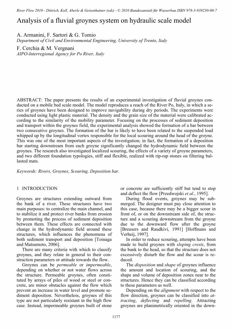
1 INTRODUCTION
Groynes are structures extending outward from the bank of a river. These structures have two main purposes: to centralize the main channel, and to stabilize it and protect river banks from erosion by promoting the process of sediment deposition between them. These effects are connected with change in the hydrodynamic field around these structures, which influences the phenomena of both sediment transport and deposition [Toinaga and Matsumoto, 2006].
There are many criteria with which to classify groynes, and they relate in general to their con-struction parameters or attitude towards the flow.
Groynes can be permeable or impermeable, depending on whether or not water flows across the structure. Permeable groynes, often consti-tuted by arrays of piles of wood or steel or con-crete, are minor obstacles against the flow which prevent an increase in water level and promote se-diment deposition. Nevertheless, groynes of this type are not particularly resistant in the high flow case. Instead, impermeable groynes built of stone
or concrete are sufficiently stiff but tend to stop and deflect the flow [Przedwojski et al., 1995].
During flood events, groynes may be sub-merged. The designer must pay close attention to this case, because there may be a bigger scour in front of, or on the downstream side of, the struc-ture and a scouring downstream from the groyne due to the downward flow after the groyne [Breusers and Raudkivi, 1991] [Hoffmans and Verheij, 1997].
In order to reduce scouring, attempts have been made to build groynes with sloping crests, from the bank to the head, so that the structure does not excessively disturb the flow and the scour is re-duced.
The disposition and shape of groynes influence the amount and location of scouring, and the shape and volume of deposition zones near to the structures. Hence they can be classified according to these parameters as well.
Depending on the alignment with respect to the flow direction, groynes can be classified into at-tracting, deflecting and repelling. Attracting groynes are planimetrically oriented in the down-
Analysis of a fluvial groynes system on hydraulic scale model
A. Armanini, F. Sartori & G. Tomio
Department of Civil and Environmental Engineering, University of Trento, Italy
F. Cerchia & M. Vergnani AIPO-Interregional Agency for Po River, Italy
ABSTRACT: The paper presents the results of an experimental investigation of fluvial groynes con-ducted on a mobile bed scale model. The model reproduces a reach of the River Po, Italy, in which a se-ries of groynes have been designed to improve navigability during dry periods. The experiments were conducted using light plastic material. The density and the grain size of the material were calibrated ac-cording to the similarity of the mobility parameter. Focusing on the processes of sediment deposition and transport within the groynes field, the experimental analysis showed the formation of a bar between two consecutive groynes. The formation of the bar is likely to have been related to the suspended load whipped up by the longitudinal vortex responsible for the local scouring around the head of the groyne. This was one of the most important aspects of the investigation; in fact, the formation of a deposition bar starting downstream from each groyne significantly changed the hydrodynamic field between the groynes. The research also investigated localized scouring, the effects of a variety of groyne parameters, and two different foundation typologies, stiff and flexible, realized with rip-rap stones on filtering bal-lasted mats.
Keywords: Rivers, Groynes, Scouring, Deposition bar.
River Flow 2010 - Dittrich, Koll, Aberle & Geisenhainer (eds) - © 2010 Bundesanstalt für Wasserbau ISBN 978-3-939230-00-7
1177

stream direction, but they are dangerous when they are submerged, because in this case the flow downstream from the crest of the groyne is di-rected towards the bank. Deflecting groynes are perpendicular to the mainstream and are mainly used when it is necessary to push the talweg away from the bank. Repelling groynes are planimetri-cally upstream-oriented: they deflect the flow to-wards the opposite bank also if they are sub-merged.
A further classification can be made in regard to groyne head shape, which is an important de-sign parameter. A groyne head is often inclined with respect to the vertical, and this angle influ-ences the shape and size of the scour. Groynes can be straight, rounded, L-head, T-head and hockey-stick shaped [Kuhnle et al., 1999 and 2002].
Once the right type of groyne has been chosen for the project (head shape, submersible or not, permeable or not), it is of great importance that all the following parameters are taken into account, because they characterize the design of a groyne’s field: − planimetric location; − groyne orientation αp relative to the river axis; − groyne length Bp (normally to the bank) and
height; − groyne spacing Lp and number; − angle αp of the crest relative to the horizontal.
Figure 1 Scheme of the parameters that characterize the as-set of groynes. The angle β is used to define the dimension-less distance between two consecutive groynes.
The distance between the groynes is one of the most important parameters in their design. Two different criteria are used in the literature to de-termine the optimal distance. The first is based on cinematic and energetic considerations (Jansen, et al., 1979): it is ( )6.02 2 <hgL p χ , where χ [L T-2] is the Chézy friction coefficient and h is the water depth in the central part of the river.
Figure 2 Scheme difining the lawering of the bed.
The second criterion is based on an empirical rule according to which the angle, β , between two
consecutive groynes must range between °9 and °14 . The angle, β , is defined in Figure 1. In the
project reported here, the distances were first de-signed according to the first criterion, and verified by means of the numerical model, but the an-gle, β , was then used as the dimensionless dis-tance between two groynes.
2 SCALE MODEL
When constructing a physical scale model, com-plete similarity between the prototype and its model requires fulfilment of three similarity crite-ria: geometric, kinematic, and dynamic.
The first criterion is satisfied when the ratios of all corresponding linear dimensions between pro-totype and model are the same. When a model’s vertical reduction scale, λy and horizontal length scales, λx are not the same, the model is geometri-cally distorted The main advantage of geometri-cally distorted physical models is flexibility in choosing the horizontal scale. Without geometric distortion, the water depth on the model may be very small, and the model may be severely af-fected by surface tension effects and bottom fric-tion (scale effects). On the other hand, a mobile bed model with geometric distortion may have problems with slopes and friction angles of the bed materials because also dimensionless geome-tric quantities like slope do not remain unaltered.
The kinematic criterion is satisfied when the ratios between components of all the kinematic quantities (velocity, acceleration, etc.) of the pro-totype and the model are the same in space and time. The dynamic criterion is satisfied when the ratios between the forces of the prototype and model are the same at all times. In a fluvial model these similarity criteria reduce to the Froude simi-larity.
2.1 Solid transport similarity Models with mobile beds are characterized by the fact that the riverbed is made of granular material subject to the effects of the hydrodynamic field produced by the flow. Models of this type are used in studies related to erosion or deposition of solid materials. The presence of solid transport complicates the choice of the material to be used in the model. In general, a mobile bed model should perfectly reproduce the hydrodynamics, and it should respect the scale factors of the quan-tities that regulate sediment behavior to the flow. But a model of this kind is impossible to con-struct.
For dynamic similarity, the following quanti-ties are introduced: density ρ and dynamic viscos-
1178

ity μ of fluid; the bed shear stress 0τ , and water depth h; density ρs and diameter d of bed materi-al; gravity acceleration g.
On applying dimensional analysis and choos-ing as independent quantities (ρ, h and *u ), one obtains the dimensionless relationship:
0;;; 00 =⎟⎟⎠
⎞⎜⎜⎝
⎛
μτ
ρτ
ρρ d
gdghuf s (1)
The first parameter is the ratio between the densities, which is preferably written as a function of the relative submerged density:
ρρρ
Δ−
= s (2)
The second parameter is the Froude number. The third parameter is the mobility parameter,
and it is often written in terms of relative density and of shear velocity ρτ 0* =u :
dguΔ
θ2*= (3)
The fourth parameter is the grain Reynolds number. This parameter is often substituted by the characteristic diameter:
3/1
2* ⎟⎠⎞
⎜⎝⎛=
νΔgdD (4)
Complete similarity between model and proto-type requires that all four of the dimensionless groups in the model are the same as the prototype:
1**
==== DFrFr rrrrΔ (5)
This condition is unfeasible, and it is normally accepted that similarity does not perfectly respect both the mobility parameter and the Reynolds number. It is attempted, however, to make the model flow as similar as possible to that of the prototype.
The role of the mobility parameter, θ , is of great importance because it is the main factor in the transport rate; that is, of the deposition and scouring processes and of the morphological time variations.
In mobile bed models, in fact, the time scale of the morphological process is generally different from the kinematic time scale. The morphological time scale can be deduced from the one-dimensional continuity equation of the solid phase (Exner equation):
0=∂∂
+∂∂
xq
tz bb (6)
where zb = bed elevation, qb = solid transport rate per unit width, t = time and x = longitudinal coordinate. We considered the material to be uni-form size and cohesionless. On introducing the scales ratios rz, rx, rtz, e rqb, respectively for bed elevation, longitudinal distances, morphological times and of solid transport rates into eq. (6), the following relationship is obtained:
x
q
tz
z
rr
rr b= (7)
where tzr is the scale of the morphological time.
( )( )prototype
model
b
bq q
qr
b= (8)
is the scale reduction factor for the sediment transport rate. For an undistorted model, rz = rx = λ, that is:
bqtz r
r2λ
= (9)
This scale depends on the solid transport for-mula adopted. In this context we may refer to the Meyer-Peter and Müller [1948] bed load formula, in which the solid discharge qb depends on the dif-ference between Shields parameters θ and the crit-ical mobility parameter of incipient motion, θcr:
( ) 238 crb dgdq θθΔ −= (10)
A major problem concerns the critical mobility parameter. In a scale model designed according to the Froude similarity, if the material used in the model to reproduce the sediments has the same density as that of the prototype, and the grain size is reduced according to the length scale, the mo-bility parameter of the prototype and that of the model is the same.
The situation is depicted in Figure 3, where with respect to the present case the mobility pa-rameters of both the prototype and the model are reported. It is evident that the mobility parameter in this case is less than the critical one.
Table 1 Case study parameters with the material reduced ac-cording to the geometrical scale but with the same density as the prototype. Δ d50 [mm]
50*D θcr θ proto-type
1.67 1 25.4 0.038 0.128
model 1.67 0.025 0.63 0.346 0.128
1179
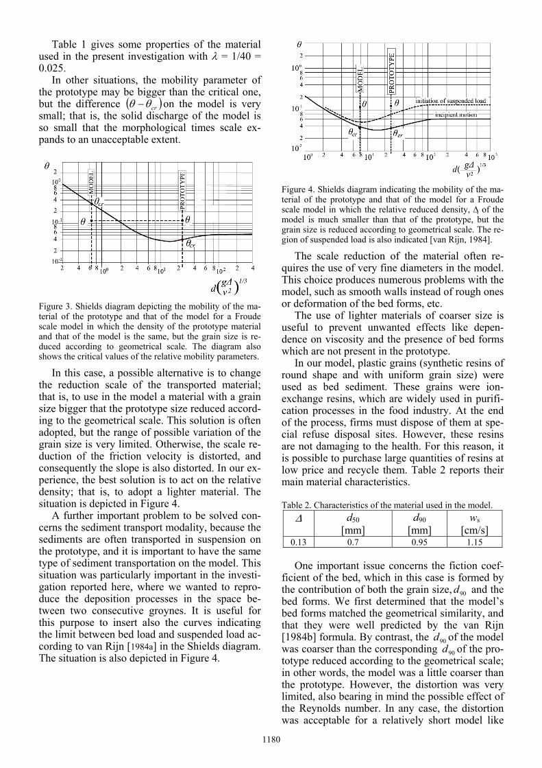
Table 1 gives some properties of the material used in the present investigation with λ = 1/40 = 0.025.
In other situations, the mobility parameter of the prototype may be bigger than the critical one, but the difference ( )crθθ − on the model is very small; that is, the solid discharge of the model is so small that the morphological times scale ex-pands to an unacceptable extent.
Figure 3. Shields diagram depicting the mobility of the ma-terial of the prototype and that of the model for a Froude scale model in which the density of the prototype material and that of the model is the same, but the grain size is re-duced according to geometrical scale. The diagram also shows the critical values of the relative mobility parameters.
In this case, a possible alternative is to change the reduction scale of the transported material; that is, to use in the model a material with a grain size bigger that the prototype size reduced accord-ing to the geometrical scale. This solution is often adopted, but the range of possible variation of the grain size is very limited. Otherwise, the scale re-duction of the friction velocity is distorted, and consequently the slope is also distorted. In our ex-perience, the best solution is to act on the relative density; that is, to adopt a lighter material. The situation is depicted in Figure 4.
A further important problem to be solved con-cerns the sediment transport modality, because the sediments are often transported in suspension on the prototype, and it is important to have the same type of sediment transportation on the model. This situation was particularly important in the investi-gation reported here, where we wanted to repro-duce the deposition processes in the space be-tween two consecutive groynes. It is useful for this purpose to insert also the curves indicating the limit between bed load and suspended load ac-cording to van Rijn [1984a] in the Shields diagram. The situation is also depicted in Figure 4.
Figure 4. Shields diagram indicating the mobility of the ma-terial of the prototype and that of the model for a Froude scale model in which the relative reduced density, Δ of the model is much smaller than that of the prototype, but the grain size is reduced according to geometrical scale. The re-gion of suspended load is also indicated [van Rijn, 1984].
The scale reduction of the material often re-quires the use of very fine diameters in the model. This choice produces numerous problems with the model, such as smooth walls instead of rough ones or deformation of the bed forms, etc.
The use of lighter materials of coarser size is useful to prevent unwanted effects like depen-dence on viscosity and the presence of bed forms which are not present in the prototype.
In our model, plastic grains (synthetic resins of round shape and with uniform grain size) were used as bed sediment. These grains were ion-exchange resins, which are widely used in purifi-cation processes in the food industry. At the end of the process, firms must dispose of them at spe-cial refuse disposal sites. However, these resins are not damaging to the health. For this reason, it is possible to purchase large quantities of resins at low price and recycle them. Table 2 reports their main material characteristics.
Table 2. Characteristics of the material used in the model.
Δ d50 [mm]
d90 [mm]
ws [cm/s]
0.13 0.7 0.95 1.15 One important issue concerns the fiction coef-
ficient of the bed, which in this case is formed by the contribution of both the grain size, 90d and the bed forms. We first determined that the model’s bed forms matched the geometrical similarity, and that they were well predicted by the van Rijn [1984b] formula. By contrast, the 90d of the model was coarser than the corresponding 90d of the pro-totype reduced according to the geometrical scale; in other words, the model was a little coarser than the prototype. However, the distortion was very limited, also bearing in mind the possible effect of the Reynolds number. In any case, the distortion was acceptable for a relatively short model like
1180

one such as this intended for the analysis of local-ized effects.
Comparisons between the hydraulic properties of the model material and that of the prototype are reported in Table 3.
Table 3. Case study parameters with light material and without geometric scale reduction. Δ d50
[mm] 50*D θcr θ
Proto-type
1.67 1 25.4 0.038 0.128
Model 0.13 0.7 7.59 0.035 0.115
2.2 Experimental setup The model was built in the Hydraulics Laboratory of the University of Trento, and it was 16 m long, 2 m wide and 0.5 m high. It represented a standard reach of the Po River in Italy, in which a series of groynes have been constructed. In order to avoid problems with slopes and material friction angles, in this model we adopted only a geometric scale λ = 1/40 = 0.025 valid for all directions (undistorted model). Once the geometric scale had been fixed, the other ratios were derived from the Froude si-milarity. In particular: ru = λ1/2 and rQ = λ5/2, where ru = velocities ratio and rQ = discharges ra-tio.
Figure 5 Sketch of the experimental set-up of the model (plant view). The model reproduced just one half width of the river.
The model reproduced just one half of the river containing the groynes. Two different types of groynes were made: one rigid and one flexible.
The foundation of the first type consisted of a plastic parallelepipedon resting on the model bot-tom. The groyne’s main structure was made of 1 cm angular stones glued together with cement (Figure 6).
The second type of groyne reproduced a spe-cial technology for groynes where the structure lies on a filtering ballasted mat made of geosyn-thetic material, ballasted with concrete cubes and coupled to the geosynthetic structure with special nails or three-dimensional geodesists. This mat-tress is located directly on the sandy soil of the river.
Figure 6. View of the rigid groynes.
The rockfill necessary to stabilize the bottom is placed on this foundation. Riprap is used for the structure of the groyne. In order to reproduce also the mechanism of the groyne’s collapse induced by local scouring on its head, the density of the material used to reproduce the structure in the model was the same as that of the bed material used in the model. This was achieved by using angular particles of Leka for the riprap superstruc-ture and Plexiglas cubes of 1 cm glued on canvas rectangles for the mats (Figure 7 ).
Figure 7. View of the flexible groynes reproduced in the model.
In the flexible groynes the foundation mattress extended for 15 cm all around the structure. The purpose of this extension was to adapt the founda-tion to the bed lowering when the localized scour-ing touched the groyne.
2.3 Configurations and tests
The tests analyzed the behavior of groynes rela-tive to changes in many parameters: − head shape: straight or rounded − foundation: stiff or flexible − spacing: 10°, 12° and 14° degrees (defined ac-
cording to Figure 2) − sloping crest: non-sloping, partially-sloping and
totally-sloping (Figure 8) − orientation angle αp: 90° or 60°
1181
0.00
0.05
0.10
0.15
0.20
0.25
0.30
1 2α p = 90° α p = 60°
°= 10α°= 12α °= 10α°= 12α
av
b
hz
⎟⎟⎠
⎞⎜⎜⎝
⎛ Δ
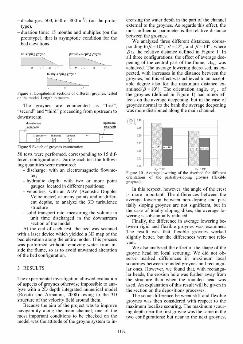
− discharges: 500, 650 or 800 m3/s (on the proto-type).
− duration time: 15 months and multiples (on the prototype), that is asymptotic condition for the bed elevations .
Figure 8. Longitudinal sections of different groynes, tested on the model. Length in meters.
The groynes are enumerated as “first”, “second” and “third” proceeding from upstream to downstream.
Figure 9 Sketch of groynes enumeration.
50 tests were performed, corresponding to 15 dif-ferent configurations. During each test the follow-ing quantities were measured:
- discharge: with an electromagnetic flowme-ter;
- hydraulic depth: with two or more point gauges located in different positions;
- velocities: with an ADV (Acoustic Doppler Velocimeter) at many points and at differ-ent depths, to analyze the 3D turbulence structure
- solid transport rate: measuring the volume in unit time discharged in the downstream section of the model.
At the end of each test, the bed was scanned with a laser device which yielded a 3D map of the bed elevation along the entire model. This process was performed without removing water from in-side the flume, so as to avoid unwanted alteration of the bed configuration.
3 RESULTS
The experimental investigation allowed evaluation of aspects of groynes otherwise impossible to ana-lyze with a 2D depth integrated numerical model (Rosatti and Armanini, 2008) owing to the 3D structure of the velocity field around them.
Because the aim of the project was to improve navigability along the main channel, one of the most important conditions to be checked on the model was the attitude of the groyne system to in-
creasing the water depth in the part of the channel external to the groynes. As regards this effect, the most influential parameter is the relative distance between the groynes.
We analyzed three different distances, corres-ponding to °= 10β , °= 12β , and °= 14β , where β is the relative distance defined in Figure 1. In all three configurations, the effect of average dee-pening of the central part of the flume, bzΔ , was achieved. The average lowering decreased, as ex-pected, with increases in the distance between the groynes, but this effect was achieved to an accept-able degree also for the maximum distance ex-amined )10( °=β . The orientation angle, pα , of the groynes (defined in Figure 1) had minor ef-fects on the average deepening, but in the case of groynes normal to the bank the average deepening was more distributed along the main channel.
Figure 10. Average lowering of the riverbed for different orientations of the partially-sloping groynes (flexible groynes).
In this respect, however, the angle of the crest is more important. The differences between the average lowering between non-sloping and par-tially sloping groynes are not significant, but in the case of totally sloping dikes, the average lo-wering is substantially reduced.
Finally, the difference in average lowering be-tween rigid and flexible groynes was examined. The result was that flexible groynes worked slightly better, but the differences were not rele-vant.
We also analyzed the effect of the shape of the groyne head on local scouring. We did not ob-serve marked differences in maximum local scourings between rounded groynes and rectangu-lar ones. However, we found that, with rectangu-lar heads, the erosion hole was further away from the structure than when the rounded head was used. An explanation of this result will be given in the section on the depositions processes.
The scour difference between stiff and flexible groynes was then considered with respect to the maximum localize scouring. The maximum scour-ing depth near the first groyne was the same in the two configurations; but near to the next groynes,
1182

the maximum scouring of the flexible groynes was more limited (Figure 11).
0.0
0.2
0.4
0.6
0.8
1.0
1.2
1.4
Groyne 1 Groyne 2
rigid
fexi
ble
rigid
fexi
ble
max⎟⎟⎠
⎞⎜⎜⎝
⎛hzbΔ
Figure 11. Maximum scouring with stiff and flexible foun-dations. With flexible groynes, the scour depth on the cen-tral spur was smaller than that at the rigid one.
The realization of rigid groynes in the river Po is rather problematic, while building up flexible groynes is easier and less expensive, so after an initial series of tests, the configuration with rigid groynes was abandoned. However, we have rea-son to believe that, apart from the differences shown in Figure 11, the most important considera-tions for the flexible groynes also apply for rigid groynes.
Figure 12. Maximum scouring at different spacings between flexible groynes. The increase of the spacing significantly influences the scouring depth near the central spur; the greatest maximum scour depth is recorded for β = 10° .
Comparison between tests with different spac-ings shows that the maximum scour was only in-fluenced by the distance with biggest relative dis-tance )10( °=β . In fact, the erosion hole near to the second groyne was considerably increased, whereas it remained the same near to the first one.
The inclination of the crest also significantly affected the local scouring.
In fact, the scour depth decreased with in-creases in the slope, as expected, ranging from a quite small effect, Δzb/h = 0.2, for the totally-sloping groynes, to a considerable effect, Δzb/h = 1.3, for the horizontal groynes (Figure 13).
0.0
0.2
0.4
0.6
0.8
1.0
1.2
1.4
Groyne 1 Groyne 2
slopi
ngno
slopi
ngto
tally
slopi
ngpa
rtial
ly
slopi
ngno
slopi
ngto
tally
slopi
ngpa
rtial
ly
max⎟⎟⎠
⎞⎜⎜⎝
⎛hzbΔ
Figure 13. Maximum scour with non-sloping, totally-sloping and partially-sloping groynes. The inclination of the crest significantly affects the scour depth; scour depth de-creases with increases in the structure slope (flexible groynes).
The last aspect analyzed was the groyne orien-tation αp. The scour size did not vary appreciably between °= 60pα , °= 90pα , but the position of the scouring hole changed significantly for
°= 60pα . In this case, in fact, the local scouring began in the upstream corner of the groynes, re-ducing its safety.
3.1 Deposition processes One of the advantages of using light material was the model’s ability to reproduce the suspended load. The correct similarity of suspended load en-abled accurate reproduction of the deposition process between groynes.
Figure 14. Mechanics of formation of the intergroyne bars.
We observed, in fact, the formation of a depo-sition bar starting downstream from each groyne and which significantly changed the hydrody-namic field between the groynes.
The formation of such a bar is likely related to the suspended load whipped up by the longitudi-nal vortex responsible for the local scouring around the head of the groin. The process is sketched in Figure 14.
The localized scouring starts in the proximity of the head of the groyne because of the stretching of the longitudinal vorticity due to longitudinal acceleration. When the bed starts being eroded, the material is brought upwards mainly as sus-pended load. The vertical secondary circulation
0.0
0.2
0.4
0.6
0.8
1.0
1.2
1.4
Groyne 1 Groyne 2
°= 10β°= 12β°= 14β
°= 10β°= 12β°= 14β
max⎟⎟⎠
⎞⎜⎜⎝
⎛hzbΔ
1183

between the groynes brings this material towards the bank and the material tends progressively to deposit in this zone. The result is the creation of a bar (Figure 14, Figure 15 and Figure 16).
The bar tends to grow in volume and in eleva-tion and to move toward the bank with discharge increasing.
0 m 50 m 100 m 150 m 200 m 250 m 300 m 350 m 400 m 450 m0 m
20 m
40 m
60 m
-13m-11m-9m-7m-5m-3m-1m1m3m5m7m Figure 15 Example of the bed elevation pattern at the end of a test on rigid groynes (Q= 800 m3/s).
The groyne’s head shape noticeably affects the shape of the bar. In fact, if the scouring hole moves toward the bank (as in the case of rounded head groynes) so does the bar, which shifts to-wards the downstream groyne and leaves the bank near the upstream groyne dangerously exposed (Figure 15). This mechanism explains why in the case of a rounded head the localized scouring is closer to the groyne.
0 m 50 m 100 m 150 m 200 m 250 m 300 m 350 m 400 m 450 m0 m
20 m
40 m
60 m
-9m-7m-5m-3m-1m1m3m5m7m Figure 16 Example of the bed elevation pattern at the end of a test on flexible upstream-oriented groynes (Q = 800 m3/s).. The angle between the groynes defined according to Figure 2 is β=10° (flexible groynes).
The effect of increasing the distance between the groynes up to a certain value is positive with respect to the bar, because the bar grows in area and volume and tends to take up all the space be-tween the groynes. However if the distance be-tween the groynes is too long )10( °≥β the bar does not reach the second groyne, which in this case is directly exposed to the main flow and is subject to deeper local scouring.
One important point concerns the effect of groyne crest inclination on the bar. We have ob-served that in the case of totally-sloping groynes (see Figure 8 for the definition) the bar disap-pears, leaving the bank unprotected. Moreover with partially-sloping groynes there is a small re-duction in the bar planimetric distribution, with a shift towards the bank.
Finally, to be stressed is that this study was performed on a straight flume, and that in the presence of a curve the results may be substantial-ly different. For this reason, the next step will be to build a flume with one or two curves and to test it.
ACKNOWLEDGEMENTS
This research is part of an applied investigation developed by CUDAM for AIPO (Realization of a mobile bed physical model for the analysis of fluvial groynes functional to improving navigation along the River Po. 09-10-2007)
REFERENCES
Breusers H.N.C., Raudkivi A.J., ”Scouring”, 1991, Ed. A.A. Balkema
Hoffmans G.J.C.M., Verheij H.J., “Scour Manual”, 1997, Ed. A.A. Balkema
Jansen, P.Ph., L. van Bendegom, J. van den Berg, M. de Vries & A. Zanen , 1979 . Principles of River Engineer-ing; The Non-Tidal Alluvial River. Pitman, London (1979) [ISBN 0-273-01139-1]
Kadota A., Suzuki K., Uijttewaal W.S.J, The shallow flow around a single groyne under submerged and emerged conditions, River Flow 2006 Vol.1
Kuhnle RA, Alonso CV, Shields FD Jr. 1999. Geometry of scour holes associated with 90° spur dikes. Journal of Hydraulic Engineering 125(9): 972-978
Kuhnle RA, Alonso CV, Douglas Shields F Jr. 2002. Local scour associated with angled spur dikes. Journal of Hy-draulic Engineering 128(12): 1087-1093
Meyer-Peter, E., and Müller, R., 1948, Formulas for bed-load transport. Proc. 2nd Meeting IAHSR, Stockholm, Sweden:1-26.
Przedwojski B., Błazejewski R., Pilarczyk K.W., River training techniques, 1995, A.A. Balkema (Rotterdam, Brookfield, Vt).
Rijn, L.C. van, 1984a, Sediment Transport, Part II: Sus-pended Load Transport, J. of Hydr. Engn., Vol. 110, No. 11: 1613-1641.
Rijn, L.C. van, 1984b, Sediment Transport, Part III: Bed forms and alluvial roughness, J. of Hydr. Engn., Vol. 110, No. 12: 1733-1754
Rosatti G. and Armanini A., 2008, A 2D numerical model for the morphological evolution in river. Proc. 31° Conv. Naz- di Idr. e C.I., Perugia, 9-12 sett. 2008. (in Italian).
Toinaga A., Matsumoto D., Diverse riverbed figuration by using skew spur-dike groups”, River Flow 2006 Vol.1.
1184