Embed Size (px)
Citation preview

RISH Ducer P11 Transducer for active or reactive power
1
in housing E16 for rail and wall mounting
Application
The transducer RISH Ducer (Figs. 1 and 2) converts to active or reactive power of a single-phase AC or three-phase system with balanced or unbalanced loads. The output signal is proportional to the measured value of the active or reactive power and is either a load-independent DC current or a load-independent DC voltage.
Input and output are electrically isolated from each other. The output is ungrounded, short and open-circuit proof and may be operated for any length of time in the open and shorted states. The output signal is limited to approx. 1.3 ´ IAN. The unit is designed to withstand impulse voltages to IEC and ANSI/IEEE regulations.
Features / Benefits
• Measuring inputs: Sine or distorted wave-forms of nominal input currents and nominal
input voltages
Meas. variables Nominal input current Nominal input voltage
Active
or reactive power
0.01 to 10 A
10 to 660 V
• Measuring output: DC current signal (load-independent) or DC voltage signal
• Measuring principle: TDM system
• 3 wattmeter method
• Narrow housing, 70 mm / Saves space and therefore costs
• Snaps onto a DIN rail or screws onto a wall or panel / Adaptable to the
circumstances at the place of installation
• Manufactured in SMD technology / Compact and reliable
• Screw terminals suitable for multistoried or solid wires / Easy wiring
without problems
•Two isolated outputs ( Optional)
• Electric isolation between output 1 and output 2 is 500V.
Fig. 1. RISH Ducer P11 transducer in housing E16
clipped onto a top-hat rail.
Overload capacity:
1 But max.250 A
Measured
quantity IN, UN
Number of
applications
Duration
of one application
Interval
between two successive applications
2 x IN continuously --- ---
10 x IN 5 15 s 5 min.
40 x IN1 1 1 s ---
1.5 x UN continuously --- ---
2 x UN 10 10 s 10 s
4 x UN 1 2 s ---
Measuring output A
Output signals:
Standard ranges of UA 10 to 13
Standard ranges of IA 14 to 17
Voltage limit under
Rext = ∞: Current limit under overload:
Span adjustment:
Output current ripple 18 : Response time:
Load-independent DC voltage UA
or load-independent DC current IA 0...10 / 1...5 / –10...0...10 V Load capacity 20 mA
External resistance Rext[kΩ] > UA [V] for one output 20 mA Rext[kΩ] > UA /V for one output
0...1/0...5/ 0...10/0...20/4...20 mA –1...0...1 / –2.5...0...2.5 / –5...0...5/ –10...0...10 / –20...0...20 mA Burden voltage ± 15 V for one output
Burden voltage ± 12 V for two output External resistance Burden voltage Rext max. [kΩ] ≤ IAN [mA]
IAN = Full output value Approx. 40 V
Approx. 1.3 ´ IAN with current output Approx. 30 mA with voltage output Approx. ± 2% < 1% p.p.
< 300 ms
Technical data
General Measured quantity:
Measuring principle: Admissible measuring range end values (calibration
factor c) to :
Measuring input E Nominal frequency fN 7 : Nominal input voltage UN :
Nominal input current IN 9: Own consumption:
Sensitivity:
Active power, reactive power Time-Division-Multiplication (pulse duration modulation) all-
electronic, input and output isolated
≥ 0.75 to 1.3 · UN · IN (single-phase AC
power) ≥ 0.75 to 1.3 · 3 · UN · IN (three-phase power) Calculation of “c” in a single-phase system:
c = unipolar range end value UN · IN Calculation of “c” in a three-phase system:
c = unipolar range end value UN · IN \ 3 When input connections are via a transformer, the primary values of UN
and IN should be used in the calculation.
50 or 60 Hz
100/ 3 , 110/ 3 , 100, 110, 200, 230, 400 or 500 V 1, 2 or 5 A < 0.1 VA per current circuit
UN · 1 mA per voltage circuit < 0.05% of range end value
8
7
1 6

RISH Ducer P11 Transducer for active or reactive power
2
Characteristic a Input E1...EN
Output A1...AN
Accuracy (according to DIN/IEC 688-1) Reference value:
Basic accuracy: Reference conditions Ambient temperature
Characteristic h
Input E1...EN Output A1...AN
Output span Exception:
Characteristic e: The largest of the 2 unipolar output levels Characteristic b: The output according to characteristic h
Class 0.5
23 °C, ± 5 K
Characteristic b
Input E1...EN Output A1...AN Given better resolution at top of range
Characteristic c Input E1...EN Output A1...AN
Live-zero output signal
Input current 0...120% IN · c
Input voltage 0...120% UN
Power factor cos φ 0...1...0
Frequency fN ± 10%
Distortion factor < 10%
Power supply UHN ± 10% (AC) UHN –15 / + 33% (DC)
External resistance 0...Rext max. with current output
Influence effects (maxima) Rext min. … ∞ with voltage output
Included in basic error
Characteristic d Input E1...EN ± 10% Output A1...AN
Variable sensitivity
Linearity error current, voltage, cosφ Frequency influence fN ±5%
Dependence on external resistance (∆Rext max.) Power supply influence UHN ± 15%
Additional errors Temperature influence (–25...+ 55°C)
Frequency influence 45 – 65 Hz Stray field influence 0.5 mT Power supply influence
UHN ± 20% Influence of common mode voltage 220 V, 50 Hz or 10 V, 1 MHz HF surge voltage influence
acc. to IEC 255-4 Class III, 2.5 kV, 1 kV, 200 Ω 1 MHz, 400 Hz acc. to ANSI/IEEE C37.90-1978
2.5 kV, 150 Ω 1 MHz, 50 Hz
Power supply
AC voltage 19 and 20:
DC voltage:
Installation data Mechanical design:
Material of housing:
± 0.2 % for one output ± 0.4 % for two o utput ± 0.05%
± 0.05% ± 0.05%
± 0.2% / 10 K for one output ± 0.3% /10 k for two outputs
± 0.5% ± 0.2%
± 0.2% ± 0.2%
± 2.0%
± 1.0%
24, 115, 120, 230 or 240 V, ± 15%,
42 to 70 Hz Power consumption approx. 5 VA for one o/p Power consumption approx. 8 VA for two o/p 24...90 (24...60V for Two output) or
90...240 V, –15 / + 33%, Power consumption approx. 5 W for one o/p Power consumption approx. 8W for two o/p
Housing type E16 Dimensions see Section “Dimensional drawings”
Lexan 940 (polycarbonate), flammability Class V-0 according to UL 94, self-extinguishing, no dripping, free of halogen
Characteristic e
Input E1...0...EN Output A1...0...AN
Characteristic f
Input E1...EN Output A1...AN
Characteristic g
Input E1...EN Output A1...AN Live-zero output signal
AN
A1
E1 EN
+E
+A
AN
A1
EN
+E
+A
E1
AN
A1
EN
+E
+A
E1
AN
-E E1
EN
+E
+A
0
A1 -A
AN
-E
EN
+E
+A
-A
E 1
AN
-E
EN
+E
+A
-A
E 1
A1=0.2x AN
A1
AN
-E
EN
+E
+A
-A
A1
AN
A1=0.2 X AN
EN
+E
+A
E1
Output characteristic
A1
A1-
E1
RISH Ducer P11 Transducer for active or reactive power
3
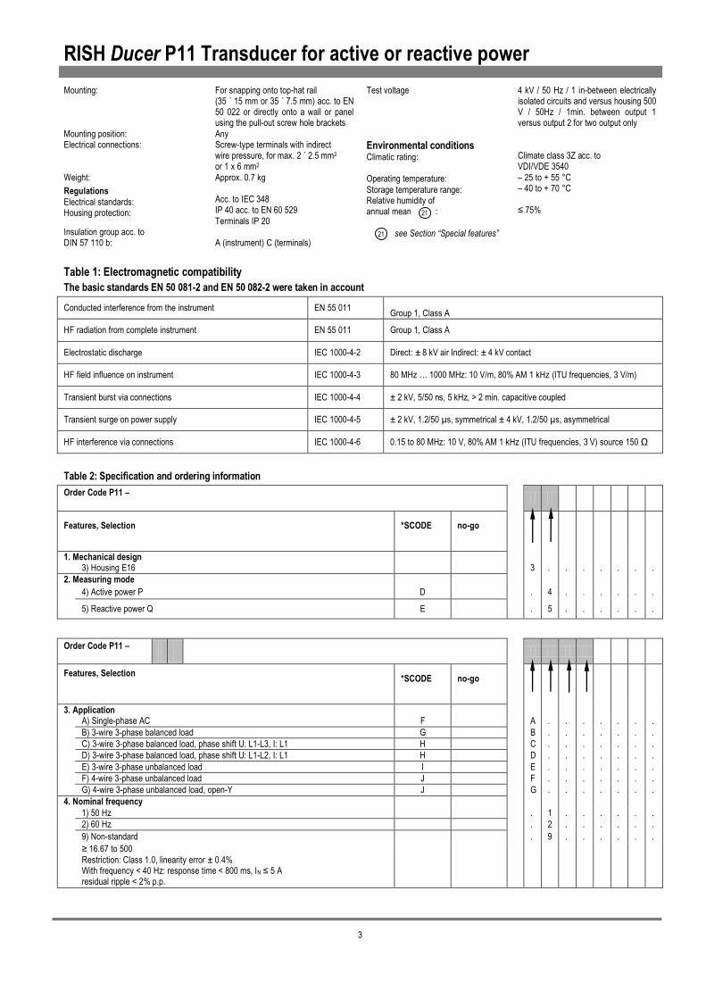
Mounting:
Mounting position: Electrical connections:
Weight:
Regulations
Electrical standards: Housing protection:
Insulation group acc. to DIN 57 110 b:
For snapping onto top-hat rail (35 ´ 15 mm or 35 ´ 7.5 mm) acc. to EN 50 022 or directly onto a wall or panel using the pull-out screw hole brackets
Any Screw-type terminals with indirect wire pressure, for max. 2 ´ 2.5 mm2 or 1 x 6 mm2
Approx. 0.7 kg Acc. to IEC 348 IP 40 acc. to EN 60 529
Terminals IP 20 A (instrument) C (terminals)
Test voltage
Environmental conditions Climatic rating: Operating temperature:
Storage temperature range: Relative humidity of annual mean :
see Section “Special features”
4 kV / 50 Hz / 1 in-between electrically isolated circuits and versus housing 500 V / 50Hz / 1min. between output 1 versus output 2 for two output only
Climate class 3Z acc. to VDI/VDE 3540
– 25 to + 55 °C – 40 to + 70 °C ≤ 75%
Table 1: Electromagnetic compatibility
The basic standards EN 50 081-2 and EN 50 082-2 were taken in account
Conducted interference from the instrument EN 55 011 Group 1, Class A
HF radiation from complete instrument EN 55 011 Group 1, Class A
Electrostatic discharge IEC 1000-4-2 Direct: ± 8 kV air Indirect: ± 4 kV contact
HF field influence on instrument IEC 1000-4-3 80 MHz … 1000 MHz: 10 V/m, 80% AM 1 kHz (ITU frequencies, 3 V/m)
Transient burst via connections IEC 1000-4-4 ± 2 kV, 5/50 ns, 5 kHz, > 2 min. capacitive coupled
Transient surge on power supply IEC 1000-4-5 ± 2 kV, 1.2/50 µs, symmetrical ± 4 kV, 1.2/50 µs, asymmetrical
HF interference via connections IEC 1000-4-6 0.15 to 80 MHz: 10 V, 80% AM 1 kHz (ITU frequencies, 3 V) source 150 Ω
Table 2: Specification and ordering information
Order Code P11 –
Features, Selection
*SCODE
no-go
1. Mechanical design 3) Housing E16 3 . . . . . . .
2. Measuring mode
4) Active power P D . 4 . . . . . .
5) Reactive power Q E . 5 . . . . . .
Order Code P11 –
Features, Selection
*SCODE
no-go
3. Application A) Single-phase AC F
A . . . . . . .
B) 3-wire 3-phase balanced load G B . . . . . . .
C) 3-wire 3-phase balanced load, phase shift U: L1-L3, I: L1 H C . . . . . . .
D) 3-wire 3-phase balanced load, phase shift U: L1-L2, I: L1 H D . . . . . . .
E) 3-wire 3-phase unbalanced load I E . . . . . . .
F) 4-wire 3-phase unbalanced load J F . . . . . . .
G) 4-wire 3-phase unbalanced load, open-Y J G . . . . . . .
4. Nominal frequency
1) 50 Hz . 1 . . . . . .
2) 60 Hz . 2 . . . . . .
9) Non-standard . 9 . . . . . .
≥ 16.67 to 500
Restriction: Class 1.0, linearity error ± 0.4% With frequency < 40 Hz: response time < 800 ms, IN ≤ 5 A residual ripple < 2% p.p.
21
21
RISH Ducer P11 Transducer for active or reactive power
4
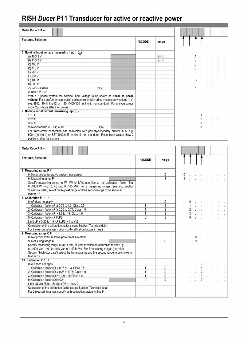
Order Code P11 –
Features, Selection
*SCODE
no-go
5. Nominal input voltage (measuring input)
A) 100/ 3 V; GHIJ
. . A . . . . .
B) 110/ 3 V; GHIJ . . B . . . . .
C) 100 V; . . C . . . . .
D) 110 V; . . D . . . . .
E) 200 V; . . E . . . . .
F) 230 V; . . F . . . . .
G) 400 V; . . G . . . . .
H) 500 V; . . H . . . . .
Z) Non-standard [V;V] . . Z . . . . .
≥ 10.00; to 660;
With a 3 phase system the nominal input voltage to be shown as phase to phase voltage. For transformer connection add semicolon with primary/secondary voltage in V,
e.g. 6600/110 (in line D) or 120;14400/120 (in line Z, non-standard). For uneven values show 2 positions after the comma
6. Nominal input current (measuring input) 9
1) 1 A; . . . 1 . . . .
2) 2 A; . . . 2 . . . .
3) 5 A; . . . 3 . . . .
9) Non-standard ≥ 0.01; to 10; [A;A] . . . 9 . . . .
For transformer connection add semicolon with primary/secondary current in A, e.g. 500/1 (in line 1) or 6.67;1600/6.67 (in line 9, non-standard). For uneven values show 2 positions after the comma
Order Code P11 –
Features, Selection
*SCODE
no-go
7. Measuring range P 6
0) Not provided for active power measurement D 0 . . . . . . .
9) Measuring range P E 9 . . . . . . .
Specify measuring range in W, kW or MW; attention to the calibration factor. E.g. 0...1000 W, –40...0...40 kW, 0...100 MW. For 2 measuring ranges (see also Section
“Technical data”) select the highest range and the second range to be shown in feature 18
8. Calibration P 1 2
0) cP does not apply D . 0 . . . . . .
1) Calibration factor cP ≥ 0.75 to 1.3; Class 0.5 T E . 1 . . . . . .
2) Calibration factor cP ≥ 0.25 to 0.74; Class 1.0 T E . 2 . . . . . .
3) Calibration factor cP > 1.3 to 1.5; Class 1.0 T E . 3 . . . . . .
9) Calibration factor cP1/cP2 U E . 9 . . . . .
Limit cP ≥ 0.25 to 1.5; cP1:cP2 > 1 to ≤ 2
Calculation of the calibration factor c sees Section “Technical data”. For 2 measuring ranges specify both calibration factors in line 9
9. Measuring range Q 6 0) Not provided for reactive power measurement E . . 0 . . . . .
9) Measuring range Q D . . 9 . . . . .
Specify measuring range in Var, k Var, M Var; attention do calibration factor! E.g.
0...1000 Var, –40...0...40 k Var, 0...100 M Var. For 2 measuring ranges (see also Section “Technical data”) select the highest range and the second range to be shown in feature 19
10. Calibration Q 1 2 0) cQ does not apply E . . . 0 . . . .
1) Calibration factor cQ ≥ 0.75 to 1.3; Class 0.5 T D . . . 1 . . . .
2) Calibration factor cQ ≥ 0.25 to 0.74; Class 1.0 T D . . . 2 . . . .
3) Calibration factor cQ > 1.3 to 1.5; Class 1.0 T D . . . 3 . . . .
9) Calibration factor cQ1/cQ2 U D . . . 9 . . . .
Limit cQ ≥ 0.25 to 1.5; cQ1:cQ2 > 1 to ≤ 2
Calculation of the calibration factor c sees Section “Technical data”.
For 2 measuring ranges specify both calibration factors in line 9
8
RISH Ducer P11 Transducer for active or reactive power
5
Order Code P11 –
Features, Selection
*SCODE
no-go
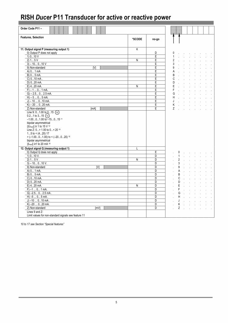
11. Output signal P (measuring output 1) K 0) Output P does not apply D 0 . . . . . . .
1) 0...10 V E 1 . . . . . . .
2) 1... 5 V N E 2 . . . . . . .
3) – 10... 0...10 V E 3 . . . . . . .
9) Non-standard [V] E 9 . . . . . . .
A) 0... 1 mA E A . . . . . . .
B) 0... 5 mA. E B . . . . . . .
C) 0...10 mA . E C . . . . . . .
D) 0...20 mA. E D . . . . . . .
E) 4...20 mA. N E E . . . . . . .
F) – 1 ... 0... 1 mA. E F . . . . . . .
G) – 2.5... 0... 2.5 mA. E G . . . . . . .
H) – 5 ... 0... 5 mA. E H . . . . . . .
J) – 10 ... 0...10 mA. E J . . . . . . .
K) – 20 ... 0...20 mA. E K . . . . . . .
Z) Non-standard [mA] E Z . . . . . . .
Line 9: 0...1.00 to 0...15 0.2...1 to 3...15
–1.00...0...1.00 to –15...0...15 11 bipolar asymmetrical ||Umax|| ≥ 1 to 15 V 12 Line Z: 0...> 1.00 to 0...< 20 14
1...5 to < (4...20) 17 > (–1.00...0...1.00) to < (–20...0...20) 15
bipolar asymmetrical ||Imax|| ≥1 to 20 mA 16
12. Output signal Q (measuring output 1) L
0) Output Q does not apply E . 0 . . . . . .
1) 0...10 V. D . 1 . . . . . .
2) 1... 5 V . N D . 2 . . . . . .
3) – 10... 0...10 V. D . 3 . . . . . .
9) Non-standard [V] D . 9 . . . . . .
A) 0... 1 mA. D . A . . . . . .
B) 0... 5 mA. D . B . . . . . .
C) 0...10 mA. D . C . . . . . .
D) 0...20 mA. D . D . . . . . .
E) 4...20 mA. N D . E . . . . . .
F) –1 ... 0... 1 mA. D . F . . . . . .
G) –2.5... 0... 2.5 mA . D . G . . . . . .
H) –5 ... 0... 5 mA . D . H . . . . . .
J) –10 ... 0...10 mA . D . J . . . . . .
K) –20 ... 0...20 mA. D . K . . . . . .
Z) Non-standard [mV] D . Z . . . . . .
Lines 9 and Z: Limit values for non-standard signals see feature 11
10 to 17 see Section “Special features”
10
13

RISH Ducer P11 Transducer for active or reactive power
6
Order Code P11 –
Features, Selection
*SCODE
no-go
13. Power supply
0) Internal from voltage measuring input 0 . . . . . . .
(≥ 24 to 500 V AC) 20
1) 24 V, 50/60 Hz 1 . . . . . . .
3) 115 V, 50/60 Hz 3 . . . . . . .
4) 120 V, 50/60 Hz 4 . . . . . . .
6) 230 V, 50/60 Hz 6 . . . . . . .
7) 240 V, 50/60 Hz 7 . . . . . . .
9) Non-standard 50/60 Hz [V] 9 . . . . . . .
> 24 to 500 19
A) 24… 90 V DC, –15/+33% M
B) 90...240 V DC, –15/+33%
C) 24…60 V DC ,-15/ +33% KL
14. Special features 0) Without Y . 0 . . . . . .
1) With . 1 . . . . . .
Without special features (line 0): Order Code complete. With special feature (line 1): The features to be omitted must be marked hereafter with / (slant line) in the order code until reaching the required feature
15. Zero displacement 3 A) Zero displacement, P-output N EY . . A . . . . .
B) Zero displacement, Q-output N DY . . B . . . . .
10 to 125% in positive or negative direction, e.g. –20...0...20 MW into 0...10 mA or 4...20 mA
16. Smaller residual ripple in measuring output 18
A) ≤ 0.5% p.p. instead of < 1% p.p. Y . . . A . . . .
Restriction: Time response < 800 ms instead of < 300 ms
(not possible for nominal frequencies < 50 Hz) (for current signals only)
17. Measuring range adjustable (variable sensitivity) 4 5
A) Approx. ± 5% NY . . . . A . . .
B) Approx. ± 10% NY . . . . B . . .
Restriction: Accuracy class 1.0. Not possible with zero displacement or live-zero output
18. Second measuring range P 6
Z) Measuring range ETY . . . . . Z . .
Specify measuring range in W, kW or MW.
Specify calibration factor in feature 8, line 9
19. Second measuring range Q 6
Z) Measuring range DTY . . . . . . Z .
Specify measuring range in Var, kVar or MVar.
Specify calibration factor in feature 10, line 9
20. Improved climatic rating (DIN 40 040) 21
A) Application class HVR instead of HVE (standard) Y . . . . . . . A
21.Output Signal P or Q (measuring output 2) M
Refer Sr. No. 11 or 12

RISH Ducer P11 Transducer for active or reactive power
7
Special features
Nature of special features Nature of special features
Admissible measuring range end value
16 Bipolar asymmetrical load-independent DC current Ranges
Calibration factor ≥0.25 to 0.74 Limitation: Class 1, linearity error±0.4%
– IA + IA IA total
min. – 1.0 V min. + 1 V min. 2 V
max. – 15 V max. + 15 V max. 30 V Calibration factor ≥1.3 to 1.5Limitation: Class 1, linearity error±0.4%
Zero displacement 10 to 125% in positive or negative direction
Variable sensitivity ±5% of full scale value 17 Live-zero Ranges between 1...5 and 4...20 mA, other than the standard range 4...20 mA
Variable sensitivity ±10% of full scale value Limitation: Class 1 (not possible with zero displacement or live-zero output)
Two calibration factors (c min. 0.25; c max. 1.5) imitation: The sensitivity ratio should not exceed 1 : 2. Circuit change is achieved by soldering a wire link on the PCB
Residual ripple in output current ( for one output ) 18 ≤ 0.5% p.p. instead of < 1% p.p.
Limitation: Response time < 800 ms instead of < 300 ms (not possible for nominal frequency < 50 Hz )
Characteristic Input E1…EN
Output A1…AN interchangeable sensitivity 1 ≤ k ≤ 2
Power supply 19 with AC voltage
any voltage between 24 and 500 V, for one output & 24 and 240 for two outputs, ± 15%, 42 to 70 Hz Power consumption approx. 5VA for one output & 8VA
for two outputs apart from the standard voltages 24, 115, 120, 230 and 240 V
Example: 1. Measuring
range: 0...10 MW 3 ´ 50 000 / 100 V 2 ´ 100 / 5 A c1 = 1.154 Output 0...20 mA 2. Measuring range:
0...5 MW c2 = 0.577 Output 0...20 mA
20 without separate power supply connection Power supply from voltage
input signal *) (24 V ≤ H ≤ 500 V, fN 50 or 60 Hz for one output) (24 V ≤ H ≤ 500 V, fN 50 or 60 Hz for one output) Limitation: Reference condition: input voltage UN ± 15% Overload capacity of the input 1.2 · UN continuous 1.5 · UN 1 s With UN
≥170 V Impulse withstand voltage acc. to IEC 255-4, Cl. II: 1 kV, 1.2/50 µs, 0.5 Ws or overload capacity of the voltage input max. 680 V~, 2 s The additional power taken from the input voltage signal is approx. 5 VA*) Standard connection between: L1 and N with single phase AC current and
Open-Y connection. Others between L1 and L2 (24 V £ H £ 240 V, fN 50 or 60 Hz for two output)
Nominal frequency fN between 16 2/3 Hz and 500 Hz, other than the standard
frequencies 50 or 60 Hz Limitation: Class 1, linearity error ±0.4% With frequency < 40 Hz: Response time < 800 ms, IN ≤5 A Residual ripple < 2% p.p. Climatic rating
Nominal input voltage UN Climate class 3Z acc. to VDI/VDE 3540, but temperature continuously – 25 to + 55 °C. Relative humidity ≤ 90% annual mean (application class HVR acc. to DIN 40 040)
between 10 and 660 V, other than the standard values
100/ 3, 110/ 3, 100, 110, 200, 230, 400 or 500 V. Limitation: with UN > 500 V overload capacity 2000 V, 2 s
Nominal input current IN
Type label
9 between 0.01 and 10 A, other than the standard values 1, 2 or 5 A
Limitations: With IN > 5 A Power consumption < 0.3 VA per current circuit Overload capacity of current circuits 2 xIN continuous 10 x IN for 10 s, max. 5 times at 5 min. intervals 40 x IN for 1 s, max. 250 A, once only fN ≥ 40 Hz With IN > 8.3 A
Reference conditions IE ≤10 A
Output signal A 10
11 12
13
14
Unipolar load-independent DC voltage*Ranges between 0...1 and 0...15 V, other than the standard range 0...10 V
Bipolar symmetrical load-independent DC voltage* Ranges between – 1...0...1 and – 15...0...15 V, other than the standard range – 10...0...10 V
Bipolar asymmetrical load-independent DC voltage* Ranges
– UA + UA UA total
min. – 1.0 V min. + 1 V min. 2 V
max. – 15 V max. + 15 V max. 30 V
Live-zero* Ranges between 0.2...1 and 3...15 V, other than the standard
range 1...5 V * Limitation: UAN < 4 V Additional error: Burden dependency ∆ Rext max. = 0.2% Reference condition: external resistance 2 ´ Rext min. ± 20%
Unipolar load-independent DC current Ranges between 0...1 and 0...20 mA, other than the standard
ranges 0...1 / 0...5 / 0...10 and 0...20 mA
15 Bipolar symmetrical load-independent DC current Ranges between –
1.0...0...1.0 and – 20...0...20 mA, other than the standard ranges – 1...0...1 / – 2.5...0...2.5/ – 5...0...5 / – 10...0...10 and – 20...0...20 mA
5 IL2 10
9 IL3 6
3 IL1 2
11 UL3 8
9 UL1 2
5 IL3 7
1 IL 1
1
2
3
4
5
6
7
8
RISHABH INSTRUMENTS PVT.LTD. F-31, MIDC, SATPUR NASHIK, INDIA
RISH Ducer P11
P11–34E1 C391 00K0 60//////K
SR.No.05/01/1008
15 16
230 V 50/60 Hz
150 000/100V
50 Hz
400/5A
13 -
7 -
14+
8+
-20…20mA Rmax 600 ohm
-20…20mA Rmax 600 ohm
-100… 100 MWatt
DIN
438
07
DIN
438
07
0.5 4
21
A
N
A1 E
N
+E
+A
E1
Type designation
Works No.
Power supply
Input Nominal voltage
Nominal frequency
Nominal current
Output Output signal
External resistance
Measuring range
RISH Ducer P11 Transducer for active or reactive power
8
9 10 11 12 13 14 15 16
1 2 3 4 5 6 7 8
9 10 1 2
X X
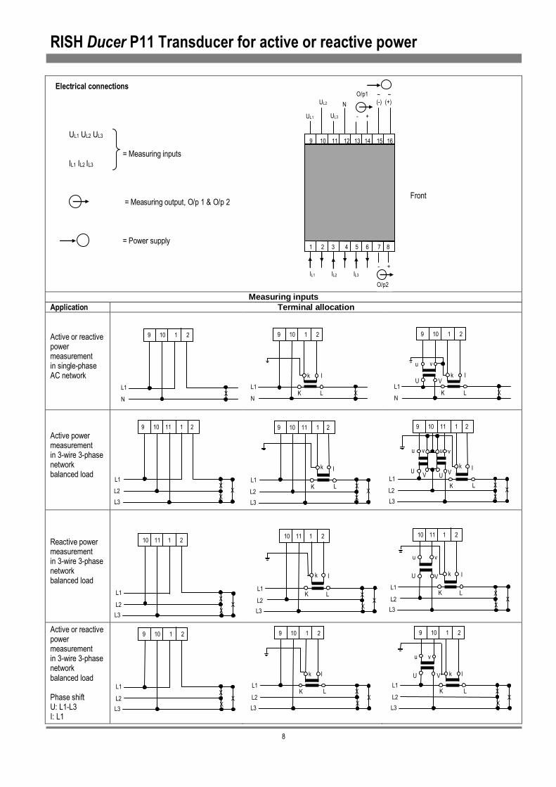
Electrical connections UL1 UL2 UL3 = Measuring inputs IL1 IL2 IL3 = Measuring output, O/p 1 & O/p 2 = Power supply
Measuring inputs Application Terminal allocation
Active or reactive power measurement in single-phase AC network
Active power measurement in 3-wire 3-phase network balanced load
Reactive power measurement in 3-wire 3-phase network balanced load
Active or reactive power measurement in 3-wire 3-phase network balanced load Phase shift U: L1-L3 I: L1
V
u
- +
O/p1
IL1 IL2 IL3
Front
UL1
UL2
UL3
N (-) (+) ~ ~
O/p2
- +
9 10 1 2
N
L1 X
9 10 1 2
N
L1 X K L
I k
N
L1 X K L
I k U V
u v
9 10 11 1 2
L2
L1 X
L3
K L
I k
U
U
u v v
U V
X X
10 11 1 2
L2
L1 X
L3
K L
I k
X X
10 11 1 2
L2
L1 X
L3
K L
I k U V
u v
X X
9 10 1 2
L2
L1 X
L3
X X
9 10 1 2
L2
L1 X
L3
K L
I k U V
v u
X X
9 10 1 2
L2
L1 X
L3
K L
I k
X
9 10 11 1 2
X L2
L1 X
L3 X
9 10 11 1 2
X L2
L1 X
L3
K L
I k
X X
10 11 1 2
L2
L1 X
L3

RISH Ducer P11 Transducer for active or reactive power
9
Measuring inputs
Application Terminal allocation
Active or reactive power measurement in 3-wire 3-phase
network balanced load Phase shift U: L1-L2
I: L1
Active or reactive power
measurement in 3-wire 3-phase network unbalanced load
Active power
measurement in 4-wire 3-phase network unbalanced load
Reactive power measurement in 4-wire 3-phase network
unbalanced load
Active or reactive Power
measurement in 4-wire 3-phase network unbalanced load
(special circuit)
Active or reactive power measurement
in 4-wire 3-phase network unbalanced load (special circuit)
X X
9 10 1 2
L2
L1 X
L3
X X
9 10 1 2
L2
L1 X
L3
K L
I k
X X
9 10 1 2
L2
L1 X
L3
K L
I k u v
U V
X X
9 10 11 1 2 5 6
L2
L1 X
L3
X X
9 10 11 1 2 5 6
L2
L1 X
L3
K L
K L
k I
I k
X X
X
X X
9 10 11 12 1 2 3 4 5 6
L2
L1
X L3
N
X X
X
X X
9 10 11 12 1 2 3 4 5 6
L2
L1
X L3
N
k I
K L
K L
k I
K L
k I
X X
X
X X
9 10 11 1 2 3 4 5 6
L2
L1
X L3
N
X X
X
X X
9 10 11 1 2 3 4 5 6
L2
L1
X L3
N
k I
K L
K L
k I
K L
k I
X X
X
X X
9 10 11 1 2 3 4 5 6
L2
L1
X L3
N
k I
K L
K L
k I
K L
k I
U U U
X X X
x x x
u u u
X X
X
X X
9 10 11 12 1 2 3 4 5 6
L2
L1
X L3
N
k I
K L
K L
k I
K L
k I
U U U
X X X
x x x
u u u
X X
X
X X
9 12 11 1 2 3 4 5 6
L2
L1
X L3
N
k I
K L
K L
k I
K L
k I
U U V V
v v u u
Delta connection using 2 VT’ s L1 –N and L3 – N open-Y connection 3 single-pole insulated voltage transformer in the high-voltage system
3 single-pole insulated voltage transformer in the high-voltage system
v
V
X X
9 10 11 1 2 5 6
L2
L1 X
L3
K L
K L
k I
I k V U U
u v u

RISH Ducer P11 Transducer for active or reactive power
10
Ø4.
5
Dimensional drawings Fig. 3.RISH Ducer P11 in housing E16 clipped onto a hat rail (35’15mm or 35’7.5 mm,acc. to EN 50 022)
Fig. 4. RISH Ducer P11 in housing E16 with the screw hole brackets pulled out for wall mounting.
9 10 11 12 13 14 15 16
70 126
125
130
1 2 3 4 5 6 7 8
19 6.5
70
125
12
125
140
154
1 2 3 4 5 6 7 8
9 10 11 12 13 14 15 16