Embed Size (px)
Citation preview

RIOC Sportspark Renovation Phase #3 June Daniel Architect PLLC
100% Submission Summary 01/29/2021 011000-1 - 1
EXHIBIT 1:
SPECIFICATIONS
DIVISION 01 - GENERAL REQUIREMENTS
• 011000– SUMMARY • 014000 - QUALITY REQUIREMENTS
DIVISION 02 – SELECTIVE DEMOLITION
SECTION NUMBER AND TITLE
• 024119 – SELECTIVE STRUCTURE DEMOLITION
DIVISION 03 – SELF LEVELING
SECTION NUMBER AND TITLE
• 035416 – SELF-LEVELING
DIVISION 04 – UNIT MASONRY
SECTION NUMBER AND TITLE
• 042000 – UNIT MASONRY
DIVISION 06 - WOOD, PLASTICS, AND COMPOSITES
SECTION NUMBER AND TITLE
• 061000 - ROUGH CARPENTRY • 062000 – FINISH CARPENTRY • 064100 – CUSTOM CASEWORK

RIOC Sportspark Renovation Phase #3 June Daniel Architect PLLC
100% Submission Summary 01/29/2021 011000-1 - 2
DIVISION 07 – THERMAL AND MOISTURE PROTECTION
SECTION NUMBER AND TITLE
• 074200 – METAL COMPOSITE MATERIAL WALL PANEL • 075200 – ROOF FLASHING AND RELATED ROOF REPAIR WORK • 076000 – FLASHING AND SHEET METAL • 079000 – JOINT SEALER
DIVISION 08 – OPENINGS
SECTION NUMBER AND TITLE
• 081100 – METAL DOORS AND FRAMES • 083100 – ACCESS DOORS • 084226 – ALUMINUM FRAMED ENTRANCE • 084413 – GLAZED ALUMINUM CURTAIN WALLS • 085113 – ALUMINUM WINDOWS • 087100 – FINISH HARDWARE • 087300 – THRESHOLD • 088000 - GLAZING
DIVISION 09 - FINISH
• 092000 - INTERIOR PLASTER PATCHING • 092900 - GYPSUM BOARD • 093100 - CERAMIC TILE • 095000 - WOOD PANEL CEILINGS • 095100 - ACOUSTICAL CEILINGS • 095900 - WOOD FLOORING • 096500 - RESILIENT FLOORING • 098600 - GRAFFITI COATING • 099000 - PAINTING FINAL
DIVISION 10 – SPECIALTIES
SECTION NUMBER AND TITLE
• 101410 – IDENTIFYING DEVICES • 102100 – TOILET COMPARTMENT • 102200 – DEMOUNTABLE PARTITION • 102800 – TOILET AND BATH ACCESSORIES • 104413 - FIER EXTINGUISHERS AND CABINETS • 105050 – METAL LOCKERS • 108400 - GRAB BARS

RIOC Sportspark Renovation Phase #3 June Daniel Architect PLLC
100% Submission Summary 01/29/2021 011000-1 - 3
DIVISION 11 – GYMNASIUM EQUIPMENT
SECTION NUMBER AND TITLE
• 114800 – GYMNASIUM EQUIPMENT
DIVISION 12 - WINDOW SHADES
SECTION NUMBER AND TITLE
• 124813 – ENTRANCE FLOOR MATS AND FRAMES • 125000 – WINDOW SHADES

RIOC Sportspark Renovation Phase #3 June Daniel Architect PLLC
100% Submission Summary 01/29/2021 011000-1
SUMMARY - SECTION 011000
PART 1 - GENERAL
1.1 SUMMARY
A. Section includes:
1. Project information. 2. Work covered by Contract Documents. 3. Phased construction. 4. Work under separate contracts. 5. Access to site. 6. Coordination with occupants. 7. Work restrictions. 8. Specification and drawing conventions.
1.2 ACCESS TO SITE
A. General: Contractor shall have limited use of Project site for construction operations as indicated on Drawings by the Contract limits and as indicated by requirements of this Section.
B. Condition of Existing Building: Maintain portions of existing building affected by construction operations in a weathertight condition throughout construction period. Repair damage caused by construction operations.
1.3 SPECIFICATION AND DRAWING CONVENTIONS
A. Specification Content: The Specifications use certain conventions for the style of language and the intended meaning of certain terms, words, and phrases when used in particular situations. These conventions are as follows:
1. Imperative mood and streamlined language are generally used in the Specifications. The words "shall," "shall be," or "shall comply with," depending on the context, are implied where a colon (:) is used within a sentence or phrase.
2. Specification requirements are to be performed by Contractor unless specifically stated otherwise.
B. Division 01 General Requirements: Requirements of Sections in Division 01 apply to the Work of all Sections in the Specifications.
C. Drawing Coordination: Requirements for materials and products identified on the Drawings are described in detail in the Specifications. One or more of the following are used on the Drawings to identify materials and products:
1. Terminology: Materials and products are identified by the typical generic terms used in the individual Specifications Sections.

RIOC Sportspark Renovation Phase #3 June Daniel Architect PLLC
100% Submission Summary 01/29/2021 011000-1
2. Abbreviations: Materials and products are identified by abbreviations scheduled on Drawings.
3. Keynoting: Materials and products are identified by reference keynotes referencing Specification Section numbers found in this Project Manual.
PART 2 - PRODUCTS (Not Used)
PART 3 - EXECUTION (Not Used)
END OF SECTION
RIOC Sportspark Renovation Phase #3 June Daniel Architect PLLC
100% Submission Quality Requirements 01/29/2021 014000 - 1
SECTION 014000 - QUALITY REQUIREMENTS
PART 1 - GENERAL
1.1 SUMMARY
A. Section includes administrative and procedural requirements for quality assurance and quality control.
B. Testing and inspecting services are required to verify compliance with requirements specified or indicated. These services do not relieve Contractor of responsibility for compliance with the Contract Document requirements.
1. Specified tests, inspections, and related actions do not limit Contractor's other quality-assurance and -control procedures that facilitate compliance with the Contract Document requirements.
2. Requirements for Contractor to provide quality-assurance and -control services required by Architect, Owner, or authorities having jurisdiction are not limited by provisions of this Section.
C. Related Sections:
1. Divisions 02 through 12 Sections for specific test and inspection requirements.
1.2 DEFINITIONS
A. Quality-Assurance Services: Activities, actions, and procedures performed before and during execution of the Work to guard against defects and deficiencies and substantiate that proposed construction will comply with requirements.
B. Quality-Control Services: Tests, inspections, procedures, and related actions during and after execution of the Work to evaluate that actual products incorporated into the Work and completed construction comply with requirements. Services do not include contract enforcement activities performed by Architect.
C. Mockups: Full size physical assemblies that are constructed on-site. Mockups are constructed to verify selections made under sample submittals; to demonstrate aesthetic effects and, where indicated, qualities of materials and execution; to review coordination, testing, or operation; to show interface between dissimilar materials; and to demonstrate compliance with specified installation tolerances. Mockups are not Samples. Unless otherwise indicated, approved mockups establish the standard by which the Work will be judged.
1. Laboratory Mockups: Full-size, physical assemblies constructed at testing facility to verify performance characteristics.
RIOC Sportspark Renovation Phase #3 June Daniel Architect PLLC
100% Submission Quality Requirements 01/29/2021 014000 - 2
D. Preconstruction Testing: Tests and inspections performed specifically for the Project before products and materials are incorporated into the Work to verify performance or compliance with specified criteria.
E. Product Testing: Tests and inspections that are performed by an NRTL, an NVLAP, or a testing agency qualified to conduct product testing and acceptable to authorities having jurisdiction, to establish product performance and compliance with specified requirements.
F. Source Quality-Control Testing: Tests and inspections that are performed at the source, i.e., plant, mill, factory, or shop.
G. Field Quality-Control Testing: Tests and inspections that are performed on-site for installation of the Work and for completed Work.
H. Testing Agency: An entity engaged to perform specific tests, inspections, or both. Testing laboratory shall mean the same as testing agency.
I. Experienced: When used with an entity or individual, "experienced" means having successfully completed a minimum of five previous projects similar in nature, size, and extent to this Project; being familiar with special requirements indicated; and having complied with requirements of authorities having jurisdiction.
1.3 CONFLICTING REQUIREMENTS
A. Referenced Standards: If compliance with two or more standards is specified and the standards establish different or conflicting requirements for minimum quantities or quality levels, comply with the most stringent requirement. Refer conflicting requirements that are different, but apparently equal, to Architect for a decision before proceeding.
B. Minimum Quantity or Quality Levels: The quantity or quality level shown or specified shall be the minimum provided or performed. The actual installation may comply exactly with the minimum quantity or quality specified, or it may exceed the minimum within reasonable limits. To comply with these requirements, indicated numeric values are minimum or maximum, as appropriate, for the context of requirements. Refer uncertainties to Architect for a decision before proceeding.
1.4 INFORMATIONAL SUBMITTALS
A. Testing Agency Qualifications: For testing agencies specified in "Quality Assurance" Article to demonstrate their capabilities and experience. Include proof of qualifications in the form of a recent report on the inspection of the testing agency by a recognized authority.
1.5 REPORTS AND DOCUMENTS
A. Test and Inspection Reports: Prepare and submit certified written reports specified in other Sections. Include the following:
1. Date of issue.

RIOC Sportspark Renovation Phase #3 June Daniel Architect PLLC
100% Submission Quality Requirements 01/29/2021 014000 - 3
2. Project title and number. 3. Name, address, and telephone number of testing agency. 4. Dates and locations of samples and tests or inspections. 5. Names of individuals making tests and inspections. 6. Description of the Work and test and inspection method. 7. Identification of product and Specification Section. 8. Complete test or inspection data. 9. Test and inspection results and an interpretation of test results. 10. Record of temperature and weather conditions at time of sample taking and testing and
inspecting. 11. Comments or professional opinion on whether tested or inspected Work complies with
the Contract Document requirements. 12. Name and signature of laboratory inspector. 13. Recommendations on retesting and reinspecting.
B. Manufacturer's Field Reports: Prepare written information documenting tests and inspections specified in other Sections. Include the following:
1. Name, address, and telephone number of representative making report. 2. Statement on condition of substrates and their acceptability for installation of product. 3. Summary of installation procedures being followed, whether they comply with
requirements and, if not, what corrective action was taken. 4. Results of operational and other tests and a statement of whether observed performance
complies with requirements. 5. Other required items indicated in individual Specification Sections.
C. Permits, Licenses, and Certificates: For Owner's records, submit copies of permits, licenses, certifications, inspection reports, releases, jurisdictional settlements, notices, receipts for fee payments, judgments, correspondence, records, and similar documents, established for compliance with standards and regulations bearing on performance of the Work.
1.6 QUALITY ASSURANCE
A. General: Qualifications paragraphs in this article establish the minimum qualification levels required; individual Specification Sections specify additional requirements.
B. Manufacturer Qualifications: A firm experienced in manufacturing products or systems similar to those indicated for this Project and with a record of successful in-service performance, as well as sufficient production capacity to produce required units.
C. Fabricator Qualifications: A firm experienced in producing products similar to those indicated for this Project and with a record of successful in-service performance, as well as sufficient production capacity to produce required units.
D. Installer Qualifications: A firm or individual experienced in installing, erecting, or assembling work similar in material, design, and extent to that indicated for this Project, whose work has resulted in construction with a record of successful in-service performance.
E. Professional Engineer Qualifications: A professional engineer who is legally qualified to practice in jurisdiction where Project is located and who is experienced in providing
RIOC Sportspark Renovation Phase #3 June Daniel Architect PLLC
100% Submission Quality Requirements 01/29/2021 014000 - 4
engineering services of the kind indicated. Engineering services are defined as those performed for installations of the system, assembly, or product that are similar to those indicated for this Project in material, design, and extent.
F. Specialists: Certain Specification Sections require that specific construction activities shall be performed by entities who are recognized experts in those operations. Specialists shall satisfy qualification requirements indicated and shall be engaged for the activities indicated.
1. Requirements of authorities having jurisdiction shall supersede requirements for specialists.
G. Testing Agency Qualifications: An NRTL, an NVLAP, or an independent agency with the experience and capability to conduct testing and inspecting indicated, as documented according to ASTM E 329; and with additional qualifications specified in individual Sections; and where required by authorities having jurisdiction, that is acceptable to authorities.
1. NRTL: A nationally recognized testing laboratory according to 29 CFR 1910.7. 2. NVLAP: A testing agency accredited according to NIST's National Voluntary
Laboratory Accreditation Program.
H. Manufacturer's Representative Qualifications: An authorized representative of manufacturer who is trained and approved by manufacturer to observe and inspect installation of manufacturer's products that are similar in material, design, and extent to those indicated for this Project.
I. Preconstruction Testing: Where testing agency is indicated to perform preconstruction testing for compliance with specified requirements for performance and test methods, comply with the following:
1. Contractor responsibilities include the following:
a. Provide test specimens representative of proposed products and construction. b. Submit specimens in a timely manner with sufficient time for testing and analyzing
results to prevent delaying the Work. c. Build laboratory mockups at testing facility using personnel, products, and
methods of construction indicated for the completed Work. d. When testing is complete, remove test specimens, assemblies, mockups; do not
reuse products on Project.
2. Testing Agency Responsibilities: Submit a certified written report of each test, inspection, and similar quality-assurance service to Architect, with copy to Contractor. Interpret tests and inspections and state in each report whether tested and inspected work complies with or deviates from the Contract Documents.
J. Mockups: Before installing portions of the Work requiring mockups, build mockups for each form of construction and finish required to comply with the following requirements, using materials indicated for the completed Work:
1. Build mockups in location and of size indicated or, if not indicated, as directed by Architect.

RIOC Sportspark Renovation Phase #3 June Daniel Architect PLLC
100% Submission Quality Requirements 01/29/2021 014000 - 5
2. Notify Architect seven days in advance of dates and times when mockups will be constructed.
3. Demonstrate the proposed range of aesthetic effects and workmanship. 4. Obtain Architect's approval of mockups before starting work, fabrication, or construction.
a. Allow seven days for initial review and each re-review of each mockup.
5. Maintain mockups during construction in an undisturbed condition as a standard for judging the completed Work.
6. Demolish and remove mockups when directed, unless otherwise indicated.
K. Laboratory Mockups: Comply with requirements of preconstruction testing and those specified in individual Specification Sections in Divisions 02 through 49.
1.7 QUALITY CONTROL
A. Owner Responsibilities: Where quality-control services are indicated as Owner's responsibility, Owner will engage a qualified testing agency to perform these services.
1. Owner will furnish Contractor with names, addresses, and telephone numbers of testing agencies engaged and a description of types of testing and inspecting they are engaged to perform.
2. Costs for retesting and reinspecting construction that replaces or is necessitated by work that failed to comply with the Contract Documents will be charged to Contractor.
B. Contractor Responsibilities: Tests and inspections not explicitly assigned to Owner are Contractor's responsibility. Perform additional quality-control activities required to verify that the Work complies with requirements, whether specified or not.
1. Where services are indicated as Contractor's responsibility, engage a qualified testing agency to perform these quality-control services.
a. Contractor shall not employ same entity engaged by Owner, unless agreed to in writing by Owner.
2. Notify testing agencies at least 24 hours in advance of time when Work that requires testing or inspecting will be performed.
3. Where quality-control services are indicated as Contractor's responsibility, submit a certified written report, in duplicate, of each quality-control service.
4. Testing and inspecting requested by Contractor and not required by the Contract Documents are Contractor's responsibility.
5. Submit additional copies of each written report directly to authorities having jurisdiction, when they so direct.
C. Manufacturer's Field Services: Where indicated, engage a manufacturer's representative to observe and inspect the Work. Manufacturer's representative's services include examination of substrates and conditions, verification of materials, inspection of completed portions of the Work, and submittal of written reports.

RIOC Sportspark Renovation Phase #3 June Daniel Architect PLLC
100% Submission Quality Requirements 01/29/2021 014000 - 6
D. Retesting/Reinspecting: Regardless of whether original tests or inspections were Contractor's responsibility, provide quality-control services, including retesting and reinspecting, for construction that replaced Work that failed to comply with the Contract Documents.
E. Testing Agency Responsibilities: Cooperate with Architect and Contractor in performance of duties. Provide qualified personnel to perform required tests and inspections.
1. Notify Architect and Contractor promptly of irregularities or deficiencies observed in the Work during performance of its services.
2. Determine the location from which test samples will be taken and in which in-situ tests are conducted.
3. Conduct and interpret tests and inspections and state in each report whether tested and inspected work complies with or deviates from requirements.
4. Submit a certified written report, in duplicate, of each test, inspection, and similar quality-control service through Contractor.
5. Do not release, revoke, alter, or increase the Contract Document requirements or approve or accept any portion of the Work.
6. Do not perform any duties of Contractor.
F. Associated Services: Cooperate with agencies performing required tests, inspections, and similar quality-control services, and provide reasonable auxiliary services as requested. Notify agency sufficiently in advance of operations to permit assignment of personnel. Provide the following:
1. Access to the Work. 2. Incidental labor and facilities necessary to facilitate tests and inspections. 3. Adequate quantities of representative samples of materials that require testing and
inspecting. Assist agency in obtaining samples. 4. Facilities for storage and field curing of test samples. 5. Delivery of samples to testing agencies. 6. Preliminary design mix proposed for use for material mixes that require control by testing
agency. 7. Security and protection for samples and for testing and inspecting equipment at Project
site.
G. Coordination: Coordinate sequence of activities to accommodate required quality-assurance and -control services with a minimum of delay and to avoid necessity of removing and replacing construction to accommodate testing and inspecting.
1. Schedule times for tests, inspections, obtaining samples, and similar activities.
1.8 SPECIAL TESTS AND INSPECTIONS
A. Special Tests and Inspections: Owner will engage a qualified testing agency to conduct special tests and inspections required by authorities having jurisdiction as the responsibility of Owner, and as follows:
B. Special Tests and Inspections: Conducted by a qualified testing agency as required by authorities having jurisdiction, as indicated in individual Specification Sections, and as follows:
RIOC Sportspark Renovation Phase #3 June Daniel Architect PLLC
100% Submission Quality Requirements 01/29/2021 014000 - 7
1. Verifying that manufacturer maintains detailed fabrication and quality-control procedures and reviewing the completeness and adequacy of those procedures to perform the Work.
2. Notifying Architect and Contractor promptly of irregularities and deficiencies observed in the Work during performance of its services.
3. Submitting a certified written report of each test, inspection, and similar quality-control service to Architect with copy to Contractor and to authorities having jurisdiction.
4. Submitting a final report of special tests and inspections at Substantial Completion, which includes a list of unresolved deficiencies.
5. Interpreting tests and inspections and stating in each report whether tested and inspected work complies with or deviates from the Contract Documents.
6. Retesting and reinspecting corrected work.
PART 2 - PRODUCTS (Not Used)
PART 3 - EXECUTION
3.1 REPAIR AND PROTECTION
A. General: On completion of testing, inspecting, sample taking, and similar services, repair damaged construction and restore substrates and finishes.
1. Provide materials and comply with installation requirements specified in other Specification Sections or matching existing substrates and finishes. Restore patched areas and extend restoration into adjoining areas with durable seams that are as invisible as possible. Comply with the Contract Document requirements for cutting and patching in Division 01 Section "Execution."
B. Protect construction exposed by or for quality-control service activities.
C. Repair and protection are Contractor's responsibility, regardless of the assignment of responsibility for quality-control services.
END OF SECTION 014000

RIOC Sportspark Renovation Phase #3 June Daniel Architect PLLC
100% Submission Selective Structure Demolition 01/29/2021 024119 - 1
SECTION 024119 - SELECTIVE STRUCTURE DEMOLITION
PART 1 - GENERAL
1.1 SUMMARY
A. This Section includes the following:
1. Demolition and removal of selected portions of building or structure.
1.2 DEFINITIONS
A. Remove: Detach items from existing construction and legally dispose of them off-site, unless indicated to be removed and salvaged or removed and reinstalled.
B. Remove and Salvage: Detach items from existing construction and deliver them to Owner.
C. Remove and Reinstall: Detach items from existing construction, prepare them for reuse, and reinstall them where indicated.
D. Existing to Remain: Existing items of construction that are not to be removed and that are not otherwise indicated to be removed, removed and salvaged, or removed and reinstalled.
1.3 SUBMITTALS
A. Schedule of Selective Demolition Activities: Indicate detailed sequence of selective demolition and removal work, with starting and ending dates for each activity, interruption of utility services, use of elevator and stairs, and locations of temporary partitions and means of egress.
B. Predemolition Photographs: Show existing conditions of adjoining construction and site improvements, including finish surfaces, that might be misconstrued as damage caused by selective demolition operations. Comply with Division 01 Section "Photographic Documentation." Submit before Work begins.
1.4 QUALITY ASSURANCE
A. Demolition Firm Qualifications: An experienced firm that has specialized in demolition work similar in material and extent to that indicated for this Project.
B. Regulatory Requirements: Comply with governing EPA notification regulations before beginning selective demolition. Comply with hauling and disposal regulations of authorities having jurisdiction.
C. Standards: Comply with ANSI A10.6 and NFPA 241.

RIOC Sportspark Renovation Phase #3 June Daniel Architect PLLC
100% Submission Selective Structure Demolition 01/29/2021 024119 - 2
1.5 PROJECT CONDITIONS
A. Notify Architect of discrepancies between existing conditions and Drawings before proceeding with selective demolition.
B. Hazardous Materials: It is not expected that hazardous materials will be encountered in the Work.
1. Hazardous materials will be removed by Owner before start of the Work. 2. If materials suspected of containing hazardous materials are encountered, do not disturb;
immediately notify Architect and Owner. Owner will remove hazardous materials under a separate contract.
C. Storage or sale of removed items or materials on-site is not permitted.
D. Utility Service: Maintain existing utilities indicated to remain in service and protect them against damage during selective demolition operations.
1.6 WARRANTY
A. Existing Warranties: Remove, replace, patch, and repair materials and surfaces cut or damaged during selective demolition, by methods and with materials so as not to void existing warranties.
PART 2 - PRODUCTS (Not Used)
PART 3 - EXECUTION
3.1 EXAMINATION
A. Verify that utilities have been disconnected and capped.
B. Survey existing conditions and correlate with requirements indicated to determine extent of selective demolition required.
C. Inventory and record the condition of items to be removed and reinstalled and items to be removed and salvaged.
D. When unanticipated mechanical, electrical, or structural elements that conflict with intended function or design are encountered, investigate and measure the nature and extent of conflict. Promptly submit a written report to Architect.
E. Engage a professional engineer to survey condition of building to determine whether removing any element might result in structural deficiency or unplanned collapse of any portion of structure or adjacent structures during selective demolition operations.

RIOC Sportspark Renovation Phase #3 June Daniel Architect PLLC
100% Submission Selective Structure Demolition 01/29/2021 024119 - 3
3.2 UTILITY SERVICES AND MECHANICAL/ELECTRICAL SYSTEMS
A. Existing Services/Systems: Maintain services/systems indicated to remain and protect them against damage during selective demolition operations.
3.3 PREPARATION
A. Site Access and Temporary Controls: Conduct selective demolition and debris-removal operations to ensure minimum interference with roads, streets, walks, walkways, and other adjacent occupied and used facilities.
1. Comply with requirements for access and protection specified in Division 01 Section "Temporary Facilities and Controls."
B. Temporary Facilities: Provide temporary barricades and other protection required to prevent injury to people and damage to adjacent buildings and facilities to remain.
C. Temporary Shoring: Provide and maintain shoring, bracing, and structural supports as required to preserve stability and prevent movement, settlement, or collapse of construction and finishes to remain, and to prevent unexpected or uncontrolled movement or collapse of construction being demolished.
3.4 SELECTIVE DEMOLITION
A. General: Demolish and remove existing construction only to the extent required by new construction and as indicated. Use methods required to complete the Work within limitations of governing regulations and as follows:
1. Neatly cut openings and holes plumb, square, and true to dimensions required. Use cutting methods least likely to damage construction to remain or adjoining construction. Use hand tools or small power tools designed for sawing or grinding, not hammering and chopping, to minimize disturbance of adjacent surfaces. Temporarily cover openings to remain.
2. Cut or drill from the exposed or finished side into concealed surfaces to avoid marring existing finished surfaces.
3. Do not use cutting torches until work area is cleared of flammable materials. At concealed spaces, such as duct and pipe interiors, verify condition and contents of hidden space before starting flame-cutting operations. Maintain fire watch and portable fire-suppression devices during flame-cutting operations.
4. Locate selective demolition equipment and remove debris and materials so as not to impose excessive loads on supporting walls, floors, or framing.
5. Dispose of demolished items and materials promptly.
B. Existing Items to Remain: Protect construction indicated to remain against damage and soiling during selective demolition. When permitted by Architect, items may be removed to a suitable, protected storage location during selective demolition and cleaned and reinstalled in their original locations after selective demolition operations are complete.

RIOC Sportspark Renovation Phase #3 June Daniel Architect PLLC
100% Submission Selective Structure Demolition 01/29/2021 024119 - 4
3.5 CLEANING
A. Clean adjacent structures and improvements of dust, dirt, and debris caused by selective demolition operations. Return adjacent areas to condition existing before selective demolition operations began.
END OF SECTION 024119
RIOC Sportspark Renovation Phase #3 June Daniel Architect PLLC
100% Submission Cement-Based Self-Leveling Underlayment 01/29/2021 035416 - 1
SECTION 035416 CEMENT-BASED SELF-LEVELING UNDERLAYMENT
PART 1 - GENERAL 1.01 SUMMARY OF WORK
A. The Work of this Section shall include, but not be limited to, installation of hydraulic cement-based self-leveling underlayment (SLU) on slabs to the elevation required to place finish material at the contract elevation. Prepare substrate to receive the SLU and install as per this Section and per manufacturer’s recommendations.
B. Provide on all slabs to provide a uniform surface to receive finish. C. Moisture content of the concrete slabs shall be checked and documented in writing by the
Contractor to ensure the moisture content is acceptable for all materials to be placed on the slab (SLU, finish flooring).
1. Slabs shall be tested utilizing the calcium chloride moisture test and, if required by
the floor finish manufacturer or SLU manufacturer, using in-situ test probe method for relative humidity or non-destructive moisture testing for surface moisture content using non-destructive Electronic Moisture.
D. Use of the various ancillary materials listed is dependant on approval of the SLU manufacturer for use in the system with their product. Contractor must have manufacturer’s approval for each item to be used.
E. Utilize moisture mitigation material for all slabs on grade.
1.02 RELATED SECTIONS
A. Resilient Flooring. . . . . . . .Section 096500
1.03 REFERENCES
A. ASTM International (ASTM), latest editions.
C31 Standard Testing Method How to Cast the In-Field cF and iF Test Cubes C94 Standard Specification for Ready-Mixed Concrete C109 Standard Test Method for Compressive Strength of Hydraulic Mortars Using 2-inch
or [50mm] Cube Specimens C157 Standard Test Method for Length Change of Change of Hardened Hydraulic-Cement
Mortar and Concrete

RIOC Sportspark Renovation Phase #3 June Daniel Architect PLLC
100% Submission Cement-Based Self-Leveling Underlayment 01/29/2021 035416 - 2
C191 Test Using Vicat Needle to Determine Final Setting Time of (SLU) Mix C596 Standard Test Method to Determine Amount of Water Content in Concrete and
Concrete Coatings of Hydraulic Cement Grout (Non-Shrink)
C1583 Test Method Standard for Tensile Strength of Concrete Surfaces and the Bond Strength or Tensile Strength of Concrete Surfaces
F1869 Standard Test Method for Measuring Moisture Vapor Emission Rate of Concrete
Subfloor Using Anhydrous Calcium Chloride F2170 Standard Test Method for Determining Relative Humidity in Concrete Floor Slabs
Using in situ Probes F2659 Standard Guide for Preliminary Evaluation of Comparative Moisture Condition of
Concrete, Gypsum Cement and Other Floor Slabs and Screeds Using Non-Destructive Electronic Moisture
1.04 SUBMITTALS
A. Product Data Submit manufacturer’s technical data for all materials, including repair material, primer, self-
leveling underlayment, epoxy, and moisture mitigation membrane. B. Shop Drawings
Plans indicating substrates, locations, and average depths of cement-based underlayment based on survey of substrate conditions.
C. Quality Control Submittals
1. Test Reports: a. Submit independent laboratory test reports for the performance criteria
specified in Part 2 for the SLU (For products not listed).
b. Moisture testing: 1) Calcium chloride moisture test indicating substrate moisture content
is within acceptable limits to receive SLU and finish flooring. 2) Relative Humidity moisture test indicating substrate moisture content
is within acceptable limits to receive SLU and finish flooring. 3) Non-destructive, instant surface moisture test indicating substrate
surface moisture is below the acceptable range prior to receive SLU and finish flooring.
2. Certificates

RIOC Sportspark Renovation Phase #3 June Daniel Architect PLLC
100% Submission Cement-Based Self-Leveling Underlayment 01/29/2021 035416 - 3
Furnish single-source Manufacturer's certification that materials meet or exceed Specification requirements.
3. Manufacturer's Instructions: Furnish manufacturer's printed material, specifications, and application instructions for installation of all component materials to complete the Work of this Section.
4. Written Repair Procedure Submit written copies of procedures of actual process to be utilized to install self-
leveling underlayment, including surface preparation and mixing procedures. Procedure is to be signed by manufacturer’s representative for locations where drawings require manufacturer’s representative to inspect and certify compatibility of manufacturer’s product with substrate.
5. Manufacturer's Field Reports Manufacturer’s representative of single-source cement-based self-leveling underlayment
shall submit field reports of surface preparation inspection and underlayment placement. 6. Qualifications Provide proof of Manufacturer and Installer qualifications and experience specified
under “Quality Assurance”.
D. Guarantee
1. Installer's installation guarantee and manufacturer’s material warranty. 2. Manufacturer’s labor and material warranty for systems with vapor mitigating
compound.
E. Mock-up
Provide mock-up of SLU installation. 1.05 QUALITY ASSURANCE
A. Qualifications
1. Installer/Applicator: An experienced installer/ applicator, trained by the manufacturer to install their system, who has completed cement-based underlayment applications similar in material and extent to that required for this Project, and whose work has resulted in construction with a record of successful continuous in-service performance for a minimum of three (3) years.
2. Manufacturer: A minimum of four (4) years successful continuous experience in the
manufacturer of hydraulic cement-based self-leveling underlayments capable of being applied over the varied substrates of existing buildings.

RIOC Sportspark Renovation Phase #3 June Daniel Architect PLLC
100% Submission Cement-Based Self-Leveling Underlayment 01/29/2021 035416 - 4
B. Mockups
1. Before installing self-leveling underlayment, apply mockups to demonstrate quantities of materials and execution. Comply with the following requirements, using materials indicated for the completed Work.
a. Architect will select one area or surface to represent surfaces and conditions
for application on each substrate required.
1) Mock-up of installed underlayment shall be no less than 3’-0” X 3’-0” and preferably shall be 6’-0” X 6’-0”.
2) Mock-up of installed underlayment shall be prepared in-situ and
shall be retained in-situ as example of quality of installation as well as underlayment mix.
3) Mock-up of installed underlayment will be inspected no less than 7
days old.
b. Notify Owner seven days (7) in advance of dates and times when mockups will be applied.
c. Obtain Owner's approval of mockups before starting underlayment
application.
d. Maintain mockups, during underlayment application and until installation of finish flooring, in an undisturbed condition as a standard for judging the complete work.
e. Approved mockups may become part of the completed work if undisturbed
when finish flooring is installed. 1.06 DELIVERY, STORAGE, AND HANDLING
A. Deliver materials in original packages and containers, with seals unbroken, bearing manufacturer's labels indicating brand name and directions for storage, mixing with other components, and application. Do not break open manufacturer’s factory seals of any component packaging until installation.
B. Store materials to comply with manufacturer's written instructions to prevent deterioration
from moisture or other detrimental conditions. C. Keep all self-leveling underlayment components on a clean dry pallet raised up from the floor
the pallet is sitting on in a temperature-controlled and humidity-controlled, secured and locked room until actual incorporation into the Work of this Section.

RIOC Sportspark Renovation Phase #3 June Daniel Architect PLLC
100% Submission Cement-Based Self-Leveling Underlayment 01/29/2021 035416 - 5
1.07 ENVIRONMENTAL REQUIREMENTS
A. Do not install self-leveling underlayment until floor penetrations and peripheral work is completed. Where placed on new concrete, concrete slab shall have cured a minimum of 28 days for normal weight concrete and 56 days for lightweight concrete and is dependant on results of moisture testing for both SLU and finish flooring. Testing shall be done under the conditions described in B below.
B. Maintain ambient conditions to which the floor will be maintained under in-situ conditions.
Buildings that are or will be air-conditioned shall have conditions maintained at a temperature of 78oF together with 50% relative humidity for seventy-two (72) hours continuously prior to installation of underlayment and for the same period after in the space below as well as the space in which the material is being placed. Provide temporary equipment to provide such conditions. Do not utilize forced cooling or heating that produces rapid air movement, which will result in premature wicking of moisture affecting setting and surface of the SLU setting for the first 24 hours after placement. Do not install in temperatures below 50oF or over 90oF. Comply with manufacturer's written recommendations for substrate temperature and moisture content, ambient temperature and humidity, ventilation, and other conditions affecting self-leveling underlayment material’s performance.
C. Close areas to traffic during underlayment application and for a minimum twenty-four (24)
hour period after installation-application (longer if needed due to actual installation conditions or material type as recommended in writing by manufacturer).
1.08 COORDINATION
A. Coordinate cement-based underlayment with requirements of finish flooring products, including adhesives, specified in Division 9 Sections.
1. Before installing surface sealers recommended by underlayment manufacturer, if any,
verify compatibility with finish installation adhesives. 2. For existing construction, coordinate use of ACM materials encapsulant used under
requirements of section 02081 with SLU manufacturer’s requirements for substrate preparation and use of primer/bonding agent.
1.09 GUARANTEE A. Provide Manufacturer’s five-year warranty covering defects in materials. B. Provide Contractor’s two-year guarantee covering materials and workmanship that self-
leveling material will not fail or cause failure of finish material. C. For surfaces receiving moisture mitigation membrane, manufacturer’s ten-year material and
labor warranty against failure of those materials placed on the material due to the affects of moisture migration or bond.
PART 2 - PRODUCTS 2.01 MANUFACTURERS
RIOC Sportspark Renovation Phase #3 June Daniel Architect PLLC
100% Submission Cement-Based Self-Leveling Underlayment 01/29/2021 035416 - 6
A. Self-leveling underlayment and repair material
1. Ardex Inc. 400 Ardex Park Dr, Aliquippa, Pennsylvania 15001
2. Dayton Superior Chemical Division
4226 Kansas Avenue, Kansas City, KS 66108.
3. Silpro LLC 2 New England Way, Ayer, MA 01432
4. CMP Specialty Products, Inc
1445 Ford Road, Bensalem, PA 19020 5. MAPEI Corp 1144 E Newport Center Dr, Deerfield Beach, FL 33442 6. LATICRETE DRYTEK Innovative Flooring Solutions 1 Laticrete Park North, Bethany, CT 06534
7. LATICRETE SUPERCAP LLC and LATICRETE INTERNATIONAL, Inc. 1 Laticrete Park North, Bethany, Ct, 06524
8. Sika Corporation 201 Polito Ave, Lyndhurst, NJ 07071 B. Moisture Mitigation Membrane 1. Koester American Corp.
2585 Aviator Drive, Virginia Beach, VA 23453 2. Sinak
1949 W. Walnut Ave, San Diego, CA 92101
3. Ardex 400 Ardex Park Dr, Aliquippa, Pennsylvania 15001 4. CMP 1445 Ford Road, Bensalem, PA 19020
5. Silpro LLC 2 New England Way, Ayer, MA 01432
6. MAPEI Corp 1144 E Newport Center Dr, Deerfield Beach, FL 33442
7. Drytek Innovative Flooring Solutions 1 Laticrete Park North, Bethany, CT 06534

RIOC Sportspark Renovation Phase #3 June Daniel Architect PLLC
100% Submission Cement-Based Self-Leveling Underlayment 01/29/2021 035416 - 7
8. LATICRETE SUPERCAP LLC and LATICRETE International, Inc. 1 Laticrete Park North, Bethany, Ct, 06524
9. Sika Corporation 201 Polito Ave, Lyndhurst, NJ 07071
C. Material Coordination
Contractor shall provide systems and materials compatible with and acceptable to the SLU manufacturer. Where moisture mitigation membrane is placed, the Contractor shall test the installation of the SLU on the moisture mitigation membrane with the moisture mitigation membrane manufacturer to ensure proper bond is achieved and ensure the warranty against failure will be received.
2.02 MATERIALS
A. General: All self-leveling underlayments are to be hydraulic cement based materials capable of being installed in spaces subject to moisture without degradation under wet conditions. The products listed have been tested by laboratory mock-ups utilizing ASTM testing or through successful field testing. No other products will be accepted without going through the testing procedure, which is to be at the manufacturer’s cost. Use of materials specified is also dependant on manufacturer’s requirements, in which they may not permit the installation on certain substrates due to their material properties. Moisture mitigation membranes, installed prior to application of the SLU, must be acceptable to the SLU manufacturer. Contractor shall be aware that drying times for products before which installation of finishes can be placed vary between products and thus shall take that time into account in the schedule when selecting products.
B. Material/Performance Testing to be performed for product not listed – Owner will compare
the following against accepted materials. Provide photographs at all stages including the petrographic testing.
1. Sulfate testing per ASTM C114
2. Compression strength test as per ASTM C109: For both specified amount of water and with additional 1 quart listing testing at 7 days and 28 days.
3. Shrinkage testing per ASTM C596: For both specified amount of water and with
additional 1 quart listing testing at 7 days, 14 days, 21 days, and 28 days. 4. Bond tensile pull in accordance with ASTM C1583.
5. Mixing and placement - For both specified amount of water and with additional 1
quart – Petrographic analysis in accordance with ASTM C1324 a. Material Segregation during mixing
b. Material segregation after placement and hardening. Sections taken shall clearly show the bond line and the aggregate within matrix.

RIOC Sportspark Renovation Phase #3 June Daniel Architect PLLC
100% Submission Cement-Based Self-Leveling Underlayment 01/29/2021 035416 - 8
6. In-situ testing - For both specified amount of water and with additional 1 quart: Placement on a 4x4 slab of lightweight structural concrete, with photographs. If
deemed appropriate by the Owner, photographic evidence from other projects may be acceptable.
B. Self-Leveling Underlayment for placement on Hard Concrete Surface (Minimum ƒ’c = 4,000
psi)
1. Primers:
a. Ardex Primer P-51 b. Dayton Superior J-42 Primer c. Silpro C-21, Silflo Primer d. CMP AS-100 Primer e. MAPEI Planiprep SC f. LATICRETE DRYTEK Levelex Primer g. LATICRETE SUPERCAP Primer Plus h. Sika SikaLevel-01 Primer (porous
substrate) SikaLevel-02 EZ Primer (non-porous substrate including Sika MB)
2. Flash Patch:
a. Ardex SD-F Feather Finish b. Dayton Superior Sure Finish c. Silpro Skim Pro d. CMP PrepStar e. MAPEI Mapecem Fine Finish f. LATICRETE DRYTEK Skimcoat g. LATICRETE SUPERCAP Skimcoat h. Sika SikaLevel Skimcoat
3. Self-Leveling Underlayment – Self-drying (can be covered in less than 16 hours regardless of thickness):

RIOC Sportspark Renovation Phase #3 June Daniel Architect PLLC
100% Submission Cement-Based Self-Leveling Underlayment 01/29/2021 035416 - 9
a. Ardex K-15 b. Dayton Superior Levelayer
c. Silpro Silflo 220
d. CMP LF-210 & H2-O
e. MAPEI Ultraplan 1 plus PlaniLevel 450 f. DRYTEK DRYTEK Levelex Plus
D. Aggregates: 1. Provide aggregates when recommended in writing by underlayment manufacturer for
underlayment thickness required. 2. Mixed with self-leveling material: Well-graded, washed 1/8” to 1/4" stone or coarse
sand as recommended by underlayment manufacturer. 3. Preplaced Stone: 3/8” or 3/4" clean, crushed, washed stone of a single gradation as
recommended by manufacturer.
E. Water: Shall be clean New York City (potable) water free of injurious foreign matter conforming to the requirements for water specified in ASTM C94 at a temperature of not less than 50˚F nor more than 70˚F.
F. Reinforcement: For underlayment applied to wood substrates, in stair tread and platform pans
provide galvanized metal lath or other corrosion-resistant reinforcement recommended in writing by underlayment manufacturer.
G. Primer: Product of underlayment manufacturer recommended in writing for substrate,
conditions, and application indicated.
2.03 PRE-INSTALLATION MEETING
A. Conduct a pre-installation meeting with the manufacturer’s representative to review the methods and procedures, including surface preparation, for a satisfactory self-leveling underlayment installation.
B. Meeting shall occur with sufficient time to have submittal, procedures, and test panels
completed prior to work progressing.

RIOC Sportspark Renovation Phase #3 June Daniel Architect PLLC
100% Submission Cement-Based Self-Leveling Underlayment 01/29/2021 035416 - 10
PART 3 - EXECUTION 3.01 EXAMINATION
A. Examine substrates, with Installer present for conditions affecting performance of underlayment including substrate moisture content. Begin underlayment application only after unsatisfactory conditions have been corrected and substrate condition inspected and approved by the manufacturer’s representative and by Architect/Engineer. SLU installer shall not proceed until above required environmental conditions can be verified and recorded on provided Schedules for a minimum of seventy-two (72) hours prior to SLU application in respective space.
B. Perform moisture tests on concrete subfloors to determine if surfaces are sufficiently cured
and dry by either of the three following test methods. Depending on ambient conditions, one test may be more appropriate than the other due to possibility of false positives. Coordinate with underlayment manufacturer. The values indicated shall be verified with the manufacturer of the actual floor finish material:
1. Tests in accordance with ASTM F1869: Moisture vapor transmission shall not
exceed 3 pounds per 1,000 square feet in 24 hours. 2. Tests in accordance with ASTM F2170: Relative Humidity shall not exceed 75%. 3. Tests in accordance with ASTM F2659: Surface moisture shall not exceed 4%
moisture content.
3.02 PROTECTION A. Protect substrate and materials from freezing before and after installation. B. Protect adjacent finish materials and previously poured concrete slabs and SLU against spatter
during SLU placement. 3.03 REMOVAL/DEMOLITION
A. The pattern and extent of the demolition and removal of the deteriorated materials shall be
per engineer’s recommendations. The following shall be followed:
1. Overcut: The removal of the deteriorated material shall extend laterally at least 6” into sound material. A pattern outlines the extent of removal shall be established so when removal is complete, there will be no loose material left. The new substrate will be built on and around sound materials.
2. Undercut: When metal, rebar or reinforcing mesh are encountered, at least 3/4” of
the substrate material under the reinforcing shall be removed to allow proper bond between the reinforcing bars and the new material.
3. Cutback: Residual mastic on old surface shall be removed.

RIOC Sportspark Renovation Phase #3 June Daniel Architect PLLC
100% Submission Cement-Based Self-Leveling Underlayment 01/29/2021 035416 - 11
3.04 SURFACE PREPARATION
A. Existing Substrates: The surface of the existing substrate where the new self-leveling underlayment is to be applied shall be thoroughly shot-blasted and cleaned to an ICRI CSP3-5 minimum surface preparation, or greater if required by SLU manufacturer. Machine grinders with HEPA attachments such as the Hilti DG150 are acceptable for those substrates that are subject to asbestos abatement or where shot blasting equipment use is not feasible, such as cinder fill concrete, and will be able to produce the profile required by the SLU manufacturer. Use of a scarifier or scabbler is prohibited. The surfaces that are to receive new substrate material shall be free of laitance, asphalt, old paint, mastic, etc. that may inhibit bond between the old and the new material. Chemical treatment of the substrate (acid etching, citrus cleaner) is prohibited. After shot blasting/grinding the surface, notify the engineer for inspection.
1. Prepare and clean substrate according to manufacturer's written instructions for
substrate indicated. Provide clean, dry, neutral-pH substrate for underlayment application.
2. Treat nonmoving substrate cracks to prevent cracks from telegraphing (reflecting)
through underlayment. Rout any cracks and fill the cracks with the epoxy, scraping smooth and level with the substrate while broadcasting sand to allow for bonding of the SLU. After set, remove all loose sand.
a. Sikadur 52 epoxy by Sika b. Sure-inject J-56 by Dayton Superior c. Ardex ArdiSeal 2C Semi-Rigid Epoxy d. CM-10 by CMP Specialty Products, Inc. e. LATICRETE Drytek Epoxy Primer f. LATICRETE SUPERCAP MVC
3. Fill substrate voids, holes and patch the low spots with the following products to
prevent underlayment from leaking:
a. Sika top 122 plus patching grout by Sika b. Ardex SD-P by Ardex c. HD-50 or Conspec Special Patch/Special Bond Acrylic by Dayton Superior d. Fastcrete, Mascrete, or Patchco by Silpro e. CMP RampStar f. Mapei Mapecem Quickpatch

RIOC Sportspark Renovation Phase #3 June Daniel Architect PLLC
100% Submission Cement-Based Self-Leveling Underlayment 01/29/2021 035416 - 12
g. LATICRETE Drytek Patch h. LATICRETE SUPERCAP Skimcoat
B. Soft/Weak Cementitious Substrates: Mechanically remove laitance, glaze, efflorescence,
curing compounds, form-release agents, dust, dirt, grease, oil, and other contaminants that might impair underlayment bond according to manufacturer's written instructions. Install strengthening membrane composed of primer, manufacturers mesh and cementitious material (repair mortar, underlayment) from 1/8” to 1/2” depending on material and manufacturer or epoxy strengthening membrane depending on manufacturer.
3.05 APPLICATION
A. General: Mix and apply underlayment components according to manufacturer's written instructions.
1. Coordinate application of components to provide optimum underlayment-to-substrate
and intercoat adhesion.
2. At substrate expansion, isolation, and other moving joints, allow joint of same width to continue through underlayment.
B. Mixing and installation of moisture mitigation membrane. Choice of material must be based
on compatibility to self-leveling material selected to provide the proper bond. 1. Mix material in accordance with manufacturer’s instructions. 2. Provide mix and applications to provide resistance up to 25 pounds per 1,000 square
feet in 24 hours, including application of materials to provide bond to the SLU. C. Mixing of SLU 1. Provide water of exact quantity as required by manufacturer. 2. Provide mechanical mixer for mixing SLU material with water at project site. Equip
mixer with a suitable water-measuring device. 3. Use only mixers that are capable of mixing the dry SLU mix and water (and
aggregate where required) into a uniform self-leveling mix.
D. Apply primer over prepared substrate at manufacturer's recommended spreading rate.
E. Installation
1. Apply self-leveling underlayment, in accordance with the manufacturer’s instructions, to a minimum thickness of 1/8" over high points. Utilize a gage rake and/or self-adhering cut-to-length LEVELPEGs (spacing as required to meet finish) to provide a uniform average thickness and finish with a smoother to provide a level,
RIOC Sportspark Renovation Phase #3 June Daniel Architect PLLC
100% Submission Cement-Based Self-Leveling Underlayment 01/29/2021 035416 - 13
smooth plane finish, free of score marks, grooves, depressions and ripples. Finish tolerance shall be as required for finish flooring:
a. Wood floors: Finish tolerance of FF=50 and FL=35, minimum. b. All other finishes: Finish tolerance of FF=40 and FL=25, minimum.
2. Where joints are required, construct to match and coincide with joints in base slab.
Provide other joints as shown. 3. Where depth of material will be over 3/4” deep (or less depending on manufacturer’s
printed literature for that product), place in two or more lifts by providing aggregate in the mix to extend the material of the first lift(s), followed by a finish pour of 1/4" without aggregate. The proportion of aggregate to SLU shall be as recommended by the manufacturer in writing. If acceptable and recommended in writing by the manufacturer, place uniform stone loose (after priming of substrate) and place self-leveling on stone. As an alternative, place non-extended mix in 3/4” maximum lifts (or less depending on manufacturer’s recommendations for that product). Allow time between lifts as recommended by manufacturer to allow for curing and shrinkage. Prepare surface of each lift as recommended by manufacturer.
4. Provide for transition between adjacent area not scheduled to receive underlayment.
3.06 PROTECTION
A. Cure underlayment according to manufacturer's written instructions. Prevent contamination during application and curing processes. Protect all freshly deposited underlayment from premature drying and excessively hot or cold temperatures and maintain it with minimal moisture loss at a relatively constant temperature for the period of time necessary for the hydration of the cement and proper hardening of the underlayment.
B. Protect underlayment against damage by covering with suitable protective materials such as
kraft building paper, plywood, masonite or similar or in accordance with manufacturer’s recommendations until installation of finish material.
C. Protect underlayment from concentrated and rolling loads for remainder of construction
period.
D. Do not walk on or install finish flooring over underlayment for a minimum of 24 hours after placement, or longer if required by the SLU manufacturer due to material type or environmental conditions.
E. Do not install floor coverings for a minimum of 7 days.

RIOC Sportspark Renovation Phase #3 June Daniel Architect PLLC
100% Submission Cement-Based Self-Leveling Underlayment 01/29/2021 035416 - 14
3.07 FIELD QUALITY CONTROL A. Field Samples
Periodically throughout placement as recommended by manufacturer, conduct “Patty” or “Flow Ring” test to confirm proper water/cement ratio. If requested, cast three brass-molded cubes in the presence of manufacturer’s representative for compressive strength documentation.
B. Inspection Notify the Owner of the beginning of each phase of work so the Engineer or Architect-of-Record
and other Owner Representatives can make inspections. Do not proceed with installation of materials until substrates have been prepared and approved by the Engineer/Architect-of-Record and the manufacturer’s representative. The Owner may also elect to engage a licensed laboratory to take samples of the material and witness the mixing.
D. Manufacturer's Field Service Obtain services of self-leveling underlayment manufacturer's representative to inspect and
supervise substrate preparation and placement of the material. The manufacturer’s representative is to inspect the substrate to ensure their material is appropriate for the application, that jobsite environmental conditions for placement are met, and to ensure the substrate preparation is adequate and shall provide a written report of such inspection.
3.08 ACCEPTANCE OF SELF-LEVELING UNDERLAYMENT WORK A. General 1. Completed underlayment work that meets all applicable requirements will be accepted
without qualification. 2. Completed underlayment work that fails to meet one or more requirements but which
has been repaired to bring it into compliance will be accepted without qualification. 3. Failure of self-leveling underlayment to bond to substrate (as indicated by a hollow
sound when tapped), or disintegration or other failure of underlayment to perform in accordance with product data, will be considered failure of materials and workmanship. Repair or replace underlayments in areas of such failures. Underlayment work judged inadequate or deemed unacceptable due to appearance shall be replaced if so directed by the Engineer at the Contractor's expense.
4. Pay all costs incurred by the Owner in providing additional testing and/or analysis
required by this Section. 5. The Owner will pay all costs of additional testing and analysis made at its own request
that is not required by this Section or which shows concrete is in compliance with the Contract Documents.

RIOC Sportspark Renovation Phase #3 June Daniel Architect PLLC
100% Submission Cement-Based Self-Leveling Underlayment 01/29/2021 035416 - 15
B. Dimensional Tolerances
Finished underlayment exceeding the tolerances may be repaired provided that strength, durability, or appearance is not adversely affected. High spots may be removed with a terrazzo grinder, low spots filled with a cement-based patching compound, or other remedial measures performed as permitted and as acceptable to the self-leveling underlayment manufacturer.
END OF SECTION

RIOC Sportspark Renovation Phase #3 June Daniel Architect PLLC
100% Submission Unit Masonry 01/29/2021 042000 - 1
SECTION 042000 - UNIT MASONRY PART 1 - GENERAL 1.01 DESCRIPTION OF WORK
A. This Section includes, but is not limited to, the following: Provide brick masonry, concrete unit masonry, structural facing tile masonry, glazed
concrete block masonry, acoustic block masonry, fireclay flue lining work, cavity wall insulation, and other masonry Work as specified herein, as shown on the Drawings, and as needed for a complete and proper installation. The terms Concrete Masonry Unit (CMU) and Concrete Block are inter-changeable.
1.02 WORK INSTALLED BUT NOT FURNISHED UNDER THIS SECTION
A. ........................................................... Flashing and Sheet Metal Section 076000 1.04 DESIGN REQUIREMENTS
A. No air-entraining admixtures or material containing such shall be permitted in the mortar. Also, no anti-freeze compounds, calcium chloride, or other compounds, unless expressly permitted otherwise, shall be permitted in the mortar.
B. Mortar types to be used at the following locations, unless otherwise stated:
1. Face brick a. Type N (default type):
2. Concrete Masonry Unit a. Type N unless otherwise noted.
b. Load bearing masonry: Type S
1.05 REFERENCES
References and industry standards listed in this Section are applicable to the Work. Unless more restrictive criteria or differing requirements are explicitly stated in the Specifications, or mandated by governing codes or regulations, the recommendations, suggestions, and requirements described in the referenced standards shall be deemed mandatory and applicable to the Work.
A. American Society of Testing and Materials (ASTM) standards, latest editions.
A153 Standard Specification for Zinc Coating (Hot-Dip) on Iron and Steel Products.

RIOC Sportspark Renovation Phase #3 June Daniel Architect PLLC
100% Submission Unit Masonry 01/29/2021 042000 - 2
A240 Standard Specification for Heat-Resisting Chromium and Chromium Nickel Stainless Steel Plate, Sheet, and Strip for Pressure Vessels.
A615 Standard Specification for Deformed and Plain Billet - Steel Bars for Concrete
Reinforcement. A706 Standard Specifications for Low-Alloy Steel Deformed and Plain Bars for
Concrete Reinforcement. A951 Standard Specification for Steel Wire for Joint Reinforcement.
C27 Standard Classification of Fireclay and High-Alumina Refractory Brick.
C33 Standard Specification for Concrete Aggregates.
C55 Standard Specification for Concrete Building Brick.
C67 Standard Methods of Sampling and Testing Brick and Structural Clay Tile.
C90 Standard Specification for Hollow, Load-Bearing Concrete Masonry Units.
C129 Standard Specification for Non-Load-Bearing Concrete Masonry Units.
C140 Standard Methods of Sampling and Testing Concrete Masonry Units.
C144 Standard Specifications for Aggregate for Masonry Mortar.
C145 Standard Specification for Solid Load-Bearing Concrete Masonry Units.
C150 Standard Specification for Portland Cement.
C207 Standard Specification for Hydrated Lime for Masonry Purposes.
C216 Standard Specification for Facing Brick (Solid Masonry Units made from Clay or Shale).
C270 Standard Specification for Mortar for Unit Masonry.
C331 Standard Specification for Lightweight Aggregates for Concrete Masonry Units.
C404 Standard Specifications for Aggregates for Masonry Grout.
C476 Standard Specification for Grout for Reinforced and Nonreinforced Masonry. C780 Standard Test Method for Preconstruction and Construction Evaluation of
Mortars for Plain and Reinforced Unit Masonry.
C979 Standard Specification for Pigments for Integrally Colored Concrete. C1019 Method of Sampling and Testing Grout

RIOC Sportspark Renovation Phase #3 June Daniel Architect PLLC
100% Submission Unit Masonry 01/29/2021 042000 - 3
C1232 Standard Terminology of Masonry.
C1405 Standard Specification for single-fired Glazed Brick
B. Industry Standards.
1. "Standard for Concrete Masonry Units" - UL 618- Underwriters Laboratory.
2. American Welding Society – AWS D1.4 – Structural Welding Code – Reinforcing Steel
1.06 SUBMITTALS
A. Submittals for Specified Items 1. For items that are specified herein by manufacturer's name and model number,
submit a Product Schedule indicating the item description, manufacturer name, model number and any other identifying nomenclature. The Schedule will be accepted by the Owner for record purposes only. Product Data and Samples are not required for such specified items except for selection of color or similar purpose. When submitting items that are not specified herein by manufacturer's name and model number, provide complete Product Data and Samples for each item for review and approval.
B. Product Data
Submit Product Data to show compliance with specified requirements.
1. Submit complete data for masonry units. Laboratory test reports for brick shall be no more than two years old. Submit a list indicating the maximum dry weight of each type and size of CMU to be used in the project.
2. Submit complete data for reinforcement and ties, of each type.
3. Portland Cement: Brand and manufacturer's name.
4. Lime: Brand and manufacturer's name.
5. Mortar Pigments: Brand and manufacturer's name.
6. Packaged Products: Manufacturer's specifications and application instructions.
7. Sand: Location of pit, name of owner, and previous test data.
8. Masonry reinforcement, anchors
9. Insulation
10. Insulation adhesive

RIOC Sportspark Renovation Phase #3 June Daniel Architect PLLC
100% Submission Unit Masonry 01/29/2021 042000 - 4
11. Acoustic Block (Sound Absorptive CMU), including fiberglass filler.
12. Masonry cleaner, including specific masonry manufacturer’s recommended cleaning procedure for the product selected.
C. Samples
1. Submit as many face brick of each color to show the entire color range and in
quantities sufficient to determine percentages. Submit samples of face brick of special sizes and shapes, including factory fabricated corners and lip brick.
E. Quality Control Submittals
1. Schedule of Uses: By mortar type.
2. Certificates
a. Submit lightweight CMU producer’s certificate stating aggregate used is
100% lightweight, expanded shale, clay, or slate (rotary kiln) aggregate, in accordance with ASTM C331. To provide the required recycled content, it is acceptable to provide up to 20% lightweight recycled aggregate that will maintain the same fire resistance equivalent thickness of 100% expanded shale, clay, or slate without a decrease in block strength.
b. Furnish notarized Building Department affidavit from masonry
manufacturer (Form 10H) stating materials delivered to project comply with the Specification requirements.
c. Furnish notarized Building Department affidavit from masonry supplier
(Form 10J) stating materials delivered to project comply with the Specification requirements.
1.07 QUALITY ASSURANCE
A. Qualifications
1. Company specializing in the Work of this Section shall have a minimum of three years experience and at least two projects with similar quantity of materials.
2. Adhesive Anchor Installer: Installer for adhesive anchors installed in a horizontal or
upwardly inclined position supporting sustained tension loads shall be certified per ACI Appendix D9.2.2 as per Section BC 1912 of the 2014 NYC Building Code.
B. Regulatory Requirements
1. Building Code: Work of this Section shall conform to all requirements of the NYC
Building Code and all applicable regulations of governmental authorities having jurisdiction, including safety, health, noise, and anti-pollution regulations. Where more severe requirements than those contained in the Building Code are given in this Section, the requirements of this Section shall govern.
RIOC Sportspark Renovation Phase #3 June Daniel Architect PLLC
100% Submission Unit Masonry 01/29/2021 042000 - 5
C. Certifications
Masonry construction shall conform to the material acceptance, certification and inspection requirements of Section BC 1701.
1.08 DELIVERY, STORAGE, AND HANDLING
A. Deliver materials to project site in undamaged condition per ASTM guidelines. Store in an enclosed location or off the ground with waterproof covering as needed to protect all materials from moisture, contaminants, corrosion, deleterious temperature changes, and other harmful conditions.
B. Packaged Products
1. Deliver materials to the site in manufacturer's original, sealed containers. Do not
deliver materials which have exceeded shelf life limitation set forth by the manufacturer. Material containers shall bear the manufacturer's label indicating manufacturer's name, trade name of product, lot number, shelf life of product, and mix ratio (if applicable). This includes individual bags of pre-bagged mortar mixes.
2. Comply with manufacturer's printed instructions for storing and protecting
materials. 1.09 ENVIRONMENTAL REQUIREMENTS
A. Cold Weather Construction Requirements
1. Per Section BC 2104.3, cold weather construction provisions of TMS 602/ACI 530.1/ASCE 6 Article 1.8C shall be implemented when either the ambient temperature falls below 40°F or the temperature of masonry units is below 40°F.
2. Salt or other chemicals for lowering the freezing temperature of the mortar shall not
be used. B. Hot Weather Construction Requirements
Per the requirements of Section BC 2104.4, hot weather construction provisions of TMS 602/ACI 530.1/ASCE 6 Article 1.8D shall be implemented when temperatures exceed 100°F, or 90°F with a wind velocity greater than 8 mph.
C. Wetting of Clay Masonry Units
Provide prewetting of masonry for units with initial rates of absorption that require their wetting before laying (21.42 grams per 30 square inches or 0.025 ounce psi).
RIOC Sportspark Renovation Phase #3 June Daniel Architect PLLC
100% Submission Unit Masonry 01/29/2021 042000 - 6
PART 2 - PRODUCTS 2.01 MANUFACTURERS
A. Aggregate for Concrete Masonry Units (CMU)
1. Northeast Solite Corporation, Mt. Marion, N.Y.
2. Norlite Corporation, Cohoes, N.Y.
B. Reinforcement and Ties
1. Hohmann & Barnard, Inc., Hauppage, N.Y.
2. Wire-Bond, Charlotte, NC 3. Other manufacturers for specific products as specified herein.
C. Insulation
1. Dow Chemical Co., Midland, Michigan.
2. UC Industries Inc., Parsippany, NJ D. Insulation Adhesive Adhesives, mastics, compatible with air barrier systems and other contacted materials: 1. Henry Company 2. W. R. Grace & Co. E. Mortar Dropping Collection Net 1. Advanced Building Products Inc., Springvale, Maine. 2. Mortar Net USA, Ltd., Gary, Indiana 3. Hohmann and Barnard, Inc., Hauppauge, NY 4. Wire-Bond, Charlotte, NC F. Mortar Weeps 1. Mortar Net USA, Ltd., Gary, Indiana 2. Hohmann and Barnard, Inc., Hauppauge, NY 3. Wire-Bond, Charlotte, NC

RIOC Sportspark Renovation Phase #3 June Daniel Architect PLLC
100% Submission Unit Masonry 01/29/2021 042000 - 7
2.02 MATERIALS
A. Base Materials
1. Portland Cement
a. Type I ASTM C150 2. Slag cement (only use for ASTM C989, Grade Manufacture of concrete block 100 or 120.
3. Sand for Mortar Mix ASTM C144 Sand shall be washed natural sand with 100% passing the No. 8 sieve. Mix shall not contain chlorides.
4. Aggregate for CMU - 100% light- ASTM C331 weight aggregate, expanded clay shale or slate (rotary kiln process). To meet recycled content, lightweight recycled aggregate of up to 20% of total material that will maintain the same fire resistance equivalent thickness of 100% expanded shale, clay, or slate without a decrease in block strength may be used.
5. Aggregate for Masonry Grout ASTM C404 6. Hydrated Lime ASTM C207
Type "S" 7. Water: Shall be clean potable water free of injurious foreign matter conforming to the
requirements of Section BC 1903.4.
8. Premixed sand and lime for mortar mixes is not permitted. The use of batched
material by Spec-Mix and factory-packaged cement-lime-pigment by major mortar manufacturers is permitted. Each individual bag of material shall have the manufacturer's label identifying the mortar type.
B. Brick
1. Modular Face Brick: Clay or shale, ASTM C216 (solid), grade SW, type FBX, or
ASTM C652 (hollow), grade SW, type HBX of size 35/8" x 2¼" x 75/8" (nominal dimensions 4" x 22/3" x 8"). Cores holes shall be a minimum of 1” from faces of brick. Colors and textures as selected by the Project Architect. Where indicated on the Drawings or in the Specifications, the manufacturer and brick are the Basis of Design. Special sizes and shapes as shown on the Drawings or specified herein. Brick shall be manufactured to special sizes and shapes for corners, brick arches/lintels, and other locations and are not to be cut in the field from the standard

RIOC Sportspark Renovation Phase #3 June Daniel Architect PLLC
100% Submission Unit Masonry 01/29/2021 042000 - 8
brick. Brick shall be tested for efflorescence in accordance with ASTM Test Methods C67 and the rating shall be ”Not Effloresced”.
a. Lipped brick, such as are used above relieving angles and lintels, shall be
manufactured with the lip portion having dimensions not less than 5/8" high and 3/4" deep. Provide brick with larger lip dimensions when recommended by brick manufacturer. When recommended by the manufacturer, lipped brick may be cut to the required dimensions from solid brick in the factory, provided that cuts are carefully made to a 90 degree interior angle and do not extend past this angle.
2. Building Brick (Common Brick): Clay or shale, ASTM C62 (solid), grade SW, or
ASTM C652 (hollow), grade SW, modular size unless indicated otherwise on Drawings. Special sizes and shapes as shown on the Drawings or specified herein.
C. Concrete Masonry Units (CMU)
1. Types
a. Hollow Load-Bearing: ASTM C90. Aggregate shall conform to ASTM
C331.
2. Size
a. Nominal face dimension 8" x 16" or 8"x18", except as noted otherwise.
3. Unit weight: Unit weight of concrete for CMU not to exceed 90 pcf when tested in accordance with ASTM C140 (105 pcf for the high strength CMU).
D. Joint Reinforcement and Ties
1. Material
a. Reinforcement and Ties for Exterior Walls (includes back-up walls of
cavity wall systems): Formed from stainless steel, 18-8, type 304.
1) Sheet steel: (No. 2B Finish), cold-rolled, annealed, ASTM A240.
2) Wire steel: ASTM A951.
b. Reinforcement and Ties for Interior Walls: ASTM A951, hot-dip galvanized (after fabrication), ASTM A153.
c. Provide factory-fabricated corners and tees at corners and intersecting walls
for continuous type reinforcing, such as truss type, except as indicated otherwise.
d. Width of truss and mesh reinforcement to place edge of reinforcement 1”
from each face of masonry.

RIOC Sportspark Renovation Phase #3 June Daniel Architect PLLC
100% Submission Unit Masonry 01/29/2021 042000 - 9
2. Manufactured Units. Units are listed by Hohmann & Barnard model number in
order to establish a standard for comparison. For some units model numbers are also listed for products by Wire-Bond, Charlotte, NC; and product descriptions shall be the same as for the Hohmann & Barnard products. Deliver all units with manufacturer’s printed installation instructions.
a. Exterior Walls - Brick with Concrete Backup -All items to be stainless steel
except for seismic clips:
Provide Flexible Channel Slot Brick Tie; channel slot end to be 16 gage minimum, 1" wide. Tie diameter 3/16" of length to provide 2" embedment in brick. Channel Anchor Slots, 14 gage minimum. Provide multi-grooved rigid PVC Seismiclips for seismic interlock system. Provide 3/16" diameter Type 304 stainless steel continuous joint reinforcement wire. H&B: #363-BT Vee Byna Brick tie, #362 Gripstay Channel, #187-A seismiclips and continuous joint reinforcement wire. Anchors for channel to be Type 304 stainless nail-in type. Wire-Bond: #2102-O with channel slot end offset triangular tie, #1302 channel slot, #3690 plastic seismiclips and continuous joint reinforcement wire. Anchors for channel to be Type 304 stainless nail-in type
b. Interior Concrete Masonry Unit Walls – All items to be hot-dip galvanized: LOX-ALL #120 Truss-Mesh, 9 gage, of proper width for wall thickness. Deformations along each longitudinal rod for mortar bonding. Wire-Bond Truss Type Series 300.
c. Interior Concrete Masonry Unit Walls (Non-Loading Bearing) - All items to
be hot-dip galvanized:
1) At Partition Junctures: #MWT, 1/2” square by 16 gage, of proper width for wall thickness. Wire-Bond #1900 Mesh Wall Tie.
2) For Wall Carried up Separately: #344 steel straps, 1/4" x 11/2" x 8”
with 2 bent ends (90 degrees). Wire-Bond #3000Z Rigid Steel Tie.
E. Miscellaneous Accessories
1. Weeps: High Density polyester, polypropylene, or polyethylene woven mesh, 90% open, full height of adjacent brick x full width of joint. Recessed 1/4" from face of brick, and extending to back of brick. Color to be selected by Architect from manufacturer’s standard colors.
a. “Weep Vent” by Mortar Net
b. “Mortar-Trap Weep Vent” by Hohmann & Barnard.

RIOC Sportspark Renovation Phase #3 June Daniel Architect PLLC
100% Submission Unit Masonry 01/29/2021 042000 - 10
2. Mortar Collection/Deflection Device: High density polyethylene, polyester, or polypropylene open woven mesh of width to fill entire cavity after installation of the insulation. Provide double layer of material to ensure cavity is filled. Mesh shall be installed to create an up and down effect.
a. "Mortar Break DT" by Advanced Building Products Inc. b. “Mortar Net” by Mortar Net, Inc. c. “Mortar Trap” by Hohmann & Barnard, Inc. d. “Cavity Net DT” # 3611 by Wire-Bond.
F. Reinforcing Steel
1. Deformed bars conforming to ASTM A615, Grade 60. Reinforcement to be welded shall conform to the requirements of ASTM A706, Grade 60.
2. Reinforcement in exterior construction, such as parapets, shall be galvanized in
accordance with ASTM A767 or epoxy coated in accordance with ASTM A775. Touch up coating for galvanized material shall be in accordance with ASTM A780. Touch-up epoxy coating in accordance with coating manufacturer’s instructions.
G. Insulation
1. Extruded polystyrene, rigid, ASTM C578 Type X with R-value (aged) of 5.0/inch at
75oF mean temperature when tested in accordance with ASTM C518.
a. Minimum compressive strength: 15 psi in vertical direction when tested in accordance with ASTM D1621.
b. Maximum water absorption: 0.3% by volume when tested in accordance
with ASTM C272.
c. Surface Burning Characteristics in accordance with UL tests): Flame Spread - 15, Smoke Developed - 165.
2. Product shall not be produced with or contain any of the U.S. EPA regulated CFC
compounds which are listed in the Montreal Protocol.
3. Provide Styrofoam Brand Cavity-mate by Dow Chemical.
Panel size: 16" x 96". Thickness: as shown on the Drawings. Provide each panel of full thickness indicated.
4. Adhesive: Type recommended by insulation manufacturer and air barrier
manufacturer. Compatible with insulation and substrates.
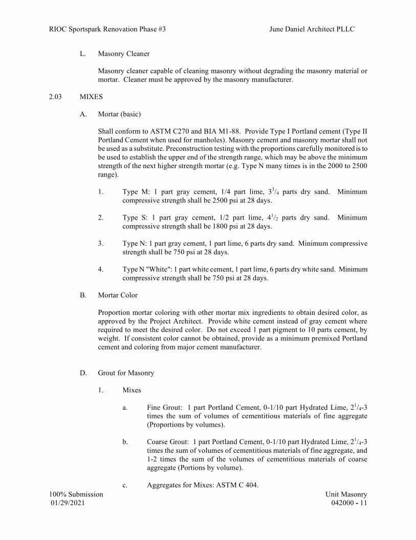
RIOC Sportspark Renovation Phase #3 June Daniel Architect PLLC
100% Submission Unit Masonry 01/29/2021 042000 - 11
L. Masonry Cleaner
Masonry cleaner capable of cleaning masonry without degrading the masonry material or mortar. Cleaner must be approved by the masonry manufacturer.
2.03 MIXES
A. Mortar (basic)
Shall conform to ASTM C270 and BIA M1-88. Provide Type I Portland cement (Type II Portland Cement when used for manholes). Masonry cement and masonry mortar shall not be used as a substitute. Preconstruction testing with the proportions carefully monitored is to be used to establish the upper end of the strength range, which may be above the minimum strength of the next higher strength mortar (e.g. Type N many times is in the 2000 to 2500 range).
1. Type M: 1 part gray cement, 1/4 part lime, 33/4 parts dry sand. Minimum
compressive strength shall be 2500 psi at 28 days.
2. Type S: 1 part gray cement, 1/2 part lime, 41/2 parts dry sand. Minimum compressive strength shall be 1800 psi at 28 days.
3. Type N: 1 part gray cement, 1 part lime, 6 parts dry sand. Minimum compressive
strength shall be 750 psi at 28 days.
4. Type N "White": 1 part white cement, 1 part lime, 6 parts dry white sand. Minimum compressive strength shall be 750 psi at 28 days.
B. Mortar Color
Proportion mortar coloring with other mortar mix ingredients to obtain desired color, as approved by the Project Architect. Provide white cement instead of gray cement where required to meet the desired color. Do not exceed 1 part pigment to 10 parts cement, by weight. If consistent color cannot be obtained, provide as a minimum premixed Portland cement and coloring from major cement manufacturer.
D. Grout for Masonry
1. Mixes
a. Fine Grout: 1 part Portland Cement, 0-1/10 part Hydrated Lime, 21/4-3 times the sum of volumes of cementitious materials of fine aggregate (Proportions by volumes).
b. Coarse Grout: 1 part Portland Cement, 0-1/10 part Hydrated Lime, 21/4-3
times the sum of volumes of cementitious materials of fine aggregate, and 1-2 times the sum of the volumes of cementitious materials of coarse aggregate (Portions by volume).
c. Aggregates for Mixes: ASTM C 404.

RIOC Sportspark Renovation Phase #3 June Daniel Architect PLLC
100% Submission Unit Masonry 01/29/2021 042000 - 12
d. Slump: 8" minimum, 11" maximum. e. Compressive Strength: At least equal to the strength of the masonry, and
not less than 2000 psi as determined by ASTM C1019 - Method of Sampling and Testing Grout.
2. Location
a. For spaces less than 2" in any direction, use fine grout.
b. For spaces 2" and more in any direction, use coarse grout.
2.04 SOURCE QUALITY CONTROL
A. The Owner will assign a Special Inspector who will inspect the masonry construction under the requirements of Section BC 1704.5.
B. Preconstruction Testing 1. Preconstruction testing of mortar properties will be done in accordance with ASTM
C780. The Contractor shall assist the Owner’s laboratory by any means necessary and shall provide the mock-up prior to beginning the installation work to allow for adjustments of the mix if necessary. Do not proceed with masonry work until the preconstruction testing is completed. Contractor shall mix mortar as it intends for the actual construction.
2. Compressive strength tests of field mixed mortar and factory batched/prepackaged
mortar are to be done during construction of the mock-up, or earlier if desired by the Contractor, to provide a benchmark for the strength based on actual field conditions and proportioning of the mortar. If mortar strengths are too high or too low, proportions and material source may be required to be modified if directed by the Architect or Engineer of Record.
3. Preconstruction testing of masonry grout properties will be done in accordance with
ASTM C1019. The Contractor shall assist the Owner’s laboratory by any means necessary and shall provide the mock-up prior to beginning the installation work to allow for adjustments of the mix if necessary. Do not proceed with masonry work until the preconstruction testing is completed. Contractor shall mix mortar as it intends for the actual construction.
PART 3 - EXECUTION 3.01 EXAMINATION
A. Examine all adjoining Work on which this Work is in anyway dependent for proper installation and workmanship. Report to the Owner any conditions that prevent the performance of this Work.

RIOC Sportspark Renovation Phase #3 June Daniel Architect PLLC
100% Submission Unit Masonry 01/29/2021 042000 - 13
3.02 PROTECTION
A. Cover top of masonry wall with waterproof plastic membrane at the end of the work period, when work is not in progress, and at other times when Work needs to be protected from rain and other precipitation. Extend cover down sides as needed to thoroughly protect the Work.
B. During cold weather, do not use wet masonry units and frozen masonry units.
C. Do not use frozen materials or lay masonry on frozen materials; remove frozen materials
from wall. Refer to Part 1 of this Section, "Environmental Requirements" for temperature restrictions.
D. Remove excess mortar from walls as soon after laying units as practicable to prevent staining
and to facilitate cleaning of wall.
E. Brace walls as needed until sufficiently set, or until intersecting walls provide lateral support. F. Prevent masonry cleaners from coming in contact with adjacent glass, metal, and other
masonry surfaces such as cast stone. Protect adjoining glass and metal surfaces and all other adjacent materials and property from masonry operations.
3.03 MIXING PROCEDURES FOR MORTAR
A. Measure material by volume or equivalent weight. In measuring by volume, measure ingredients by container. Do not measure by shovel.
B. Mix ingredients in a clean mechanical mixer for a minimum of 3 minutes, maximum of 5,
with the minimum amount of water to produce a workable consistency. Water rententivity must be appropriate for the IRA of the brick. Bricks of 3 grams per minute per 30 sq in require a lower water retentivity property to maintain production by allowing the mortar to give up the water easier to the brick.
C. Mortar that has stiffened because of evaporation of water from the mortar may be retempered
only once, and only during the first hour of placement to restore the required consistency. Do not over water to make mortar “soupy” as water retentivity must be appropriate for the IRA of the brick. Mortar shall be used within 21/2 hours after initial mixing. Limit amount of mortar batched at one time to stay within these requirements.
3.04 LAYING - GENERAL
A. Lay units true to dimensions, plumb and level, square; exterior and interior bond work in bond indicated on the Drawings or specified herein. Lay courses level and in plane with joints uniform; vertical joints spaced properly for plumb alignment. Provide masonry lines, plumb bobs, and utilize a 4-foot level to maintain wall within 1/4” of theoretical dimensions. Adjoining faces of brickwork sections, such as at expansion joints, relieving angles, etc., shall be flush with each other, unless specifically indicated otherwise on drawings.
B. Fill bed joints and cross joints solid with mortar. Furrowed bed and spotted cross joints not
permitted. For hollow block units, apply mortar full length on all bearing surfaces.

RIOC Sportspark Renovation Phase #3 June Daniel Architect PLLC
100% Submission Unit Masonry 01/29/2021 042000 - 14
C. "Tooth" temporary openings in exposed masonry walls, to maintain proper bond when closed.
D. Horizontal and Vertical Face Joints
1. Make joints uniform and 3/8" thick, unless otherwise indicated. Joints may be
slightly smaller or larger depending on brick coursing and brick fabrication tolerances.
2. Shove vertical joints tight.
3. Tool joints in exposed masonry with a concave smooth, non-staining tool, when
thumb print hard provide a neat, smooth, compacted surface.
E. Rough cut joints in masonry that are to receive plaster, to provide good plaster bond.
F. Remove excess mortar, leaving masonry surface clean.
G. Cut brick and concrete masonry units with circular masonry wet saw.
H. Build-in miscellaneous metal inserts and other items not furnished under this Section but specified to be installed under this Section.
I. Lay brick in bond patterns as shown on the Drawings. If bond is not indicated on Drawings,
use running bond, all stretchers. 3.04 FACE BRICK WORK
A. Lay face brick from scaffolding erected on face brick side of wall. Do not build or attach scaffolding into the brick face.
B. Use face brick for exterior walls, chimneys, bulkheads, and backs of parapets, except where
concrete parapets are indicated.
C. At exterior relieving angles/lintels or other brick projections on exterior face of building, brick shall be placed such that the cores are not visible. Ensure lintels and relieving angles are placed such that cores will not be visible when brick is placed at its correct location.
D. Wet clay and shale brick which have initial rates of absorption of more than 30 grams for
each 30 square inches per minute (ASTM C67). Wet brick sufficiently to prevent excess absorption of mortar moisture, but keep surface dry enough to obtain bond.
E. Lay with shoved joints, avoiding dry contacts between brick.
F. Lay not more than 5 courses before setting backup units.
G. Clean loose mortar from wall as brick is laid.
H. Leave openings for mechanical trades work, then close up solid after mechanical installations
are completed.
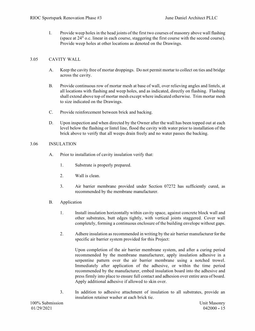
RIOC Sportspark Renovation Phase #3 June Daniel Architect PLLC
100% Submission Unit Masonry 01/29/2021 042000 - 15
I. Provide weep holes in the head joints of the first two courses of masonry above wall flashing (space at 24" o.c. linear in each course, staggering the first course with the second course). Provide weep holes at other locations as denoted on the Drawings.
3.05 CAVITY WALL
A. Keep the cavity free of mortar droppings. Do not permit mortar to collect on ties and bridge across the cavity.
B. Provide continuous row of mortar mesh at base of wall, over relieving angles and lintels, at
all locations with flashing and weep holes, and as indicated, directly on flashing. Flashing shall extend above top of mortar mesh except where indicated otherwise. Trim mortar mesh to size indicated on the Drawings.
C. Provide reinforcement between brick and backing.
D. Upon inspection and when directed by the Owner after the wall has been topped out at each
level below the flashing or lintel line, flood the cavity with water prior to installation of the brick above to verify that all weeps drain freely and no water passes the backing.
3.06 INSULATION
A. Prior to installation of cavity insulation verify that:
1. Substrate is properly prepared.
2. Wall is clean. 3. Air barrier membrane provided under Section 07272 has sufficiently cured, as
recommended by the membrane manufacturer.
B. Application
1. Install insulation horizontally within cavity space, against concrete block wall and other substrates, butt edges tightly, with vertical joints staggered. Cover wall completely, forming a continuous enclosure of the building envelope without gaps.
2. Adhere insulation as recommended in writing by the air barrier manufacturer for the
specific air barrier system provided for this Project: Upon completion of the air barrier membrane system, and after a curing period
recommended by the membrane manufacturer, apply insulation adhesive in a serpentine pattern over the air barrier membrane using a notched trowel. Immediately after application of the adhesive, or within the time period recommended by the manufacturer, embed insulation board into the adhesive and press firmly into place to ensure full contact and adhesion over entire area of board. Apply additional adhesive if allowed to skin over.
3. In addition to adhesive attachment of insulation to all substrates, provide an
insulation retainer washer at each brick tie.

RIOC Sportspark Renovation Phase #3 June Daniel Architect PLLC
100% Submission Unit Masonry 01/29/2021 042000 - 16
4. Fabricate insulation panels by means of saw, knife or other sharp tool to fit around
obstructions across cavity such as vents, louvers, piping, conduits, and other penetrations. Make insulation continuous, filling all voids. Use largest pieces of insulation possible to minimize joints. Fill cracks with material compatible with insulation, air barrier, and masonry.
3.07 BUILDING BRICK (COMMON BRICK) WORK
A. Use building brick or face brick for infilling walls of solid brick construction such as at piers, filling around structural members, solid brick parapets, and for all masonry where brick work is indicated, and for which face brick, SFT, concrete block, or other material is not shown or specified. All joints within the solid masonry construction shall be filled solid.
B. Lay up with Type N mortar, except when within 8" of cut stone work, use Type N "White"
mortar.
C. When exterior door frames are not in place at the time adjacent walls are being erected, set hot-dip galvanized steel anchors in masonry every sixth course to provide adequate anchorage for door frames to masonry when door frames are installed.
D. When brick is used for back-up wall for limestone, laying of brick shall not commence until
parging for limestone is dry.
E. Provide weep holes or open side joint as required. 3.08 CONCRETE MASONRY UNITS (CMU)
A. General
1. Lay blocks with cells vertical. Provide running bond unless shown otherwise on the Drawings or as indicated below, bonded at corner angles. Fill cores containing vertical reinforcement with masonry grout for full height, as the wall is erected.
2. Where interior partitions intersect other partitions or walls, bond together with metal
wall ties spaced 2'-0" o.c. min., vertically. Refer to Article on "Reinforcement".
3. Where interior walls are to be furred with soap units, secure furring with steel ties, spaced one for each 4-square feet.
4. Provide grout in cores of blocks at jambs, parapets, under lintels, and where
indicated on the Drawings.
5. Bond beam units shall be filled with lightweight concrete having a minimum compressive strength of 3000 psi and reinforced as shown on details.
C. Exposed and Painted Surfaces
1. Smooth, even texture, free of chips, cracks, or other imperfections and free from any
material that will stain paint.
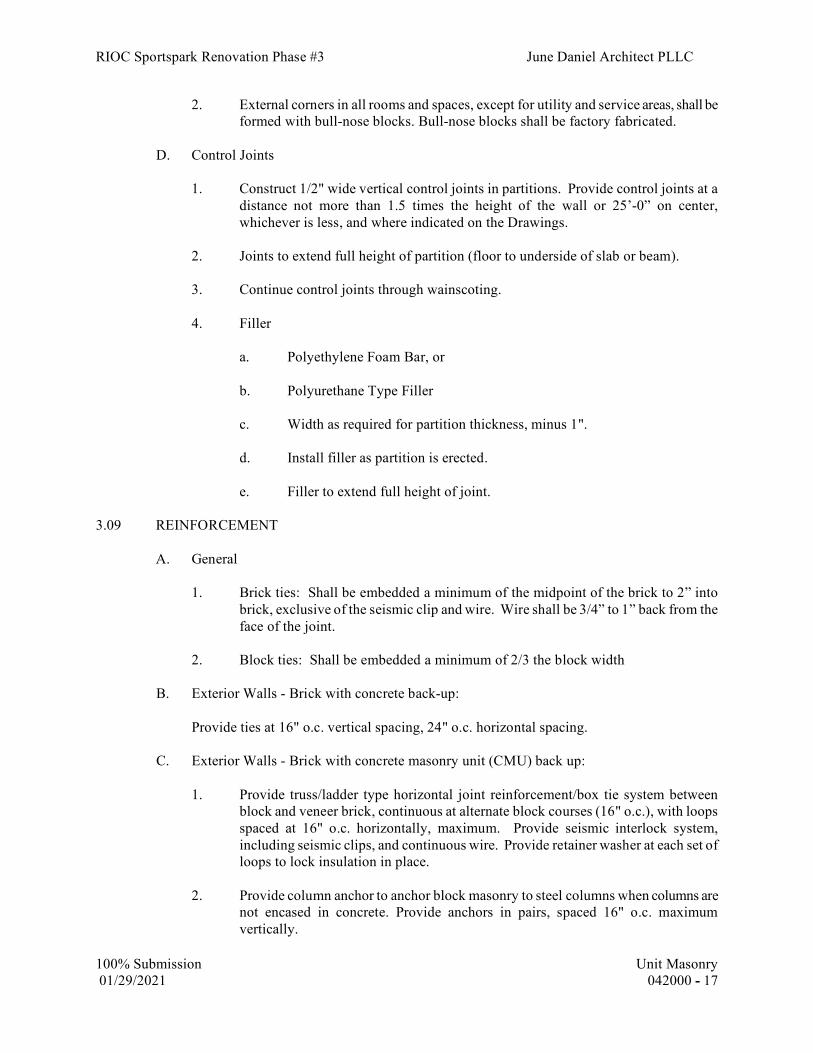
RIOC Sportspark Renovation Phase #3 June Daniel Architect PLLC
100% Submission Unit Masonry 01/29/2021 042000 - 17
2. External corners in all rooms and spaces, except for utility and service areas, shall be formed with bull-nose blocks. Bull-nose blocks shall be factory fabricated.
D. Control Joints
1. Construct 1/2" wide vertical control joints in partitions. Provide control joints at a
distance not more than 1.5 times the height of the wall or 25’-0” on center, whichever is less, and where indicated on the Drawings.
2. Joints to extend full height of partition (floor to underside of slab or beam). 3. Continue control joints through wainscoting.
4. Filler
a. Polyethylene Foam Bar, or
b. Polyurethane Type Filler
c. Width as required for partition thickness, minus 1".
d. Install filler as partition is erected.
e. Filler to extend full height of joint.
3.09 REINFORCEMENT A. General 1. Brick ties: Shall be embedded a minimum of the midpoint of the brick to 2” into
brick, exclusive of the seismic clip and wire. Wire shall be 3/4” to 1” back from the face of the joint.
2. Block ties: Shall be embedded a minimum of 2/3 the block width
B. Exterior Walls - Brick with concrete back-up:
Provide ties at 16" o.c. vertical spacing, 24" o.c. horizontal spacing.
C. Exterior Walls - Brick with concrete masonry unit (CMU) back up:
1. Provide truss/ladder type horizontal joint reinforcement/box tie system between block and veneer brick, continuous at alternate block courses (16" o.c.), with loops spaced at 16" o.c. horizontally, maximum. Provide seismic interlock system, including seismic clips, and continuous wire. Provide retainer washer at each set of loops to lock insulation in place.
2. Provide column anchor to anchor block masonry to steel columns when columns are
not encased in concrete. Provide anchors in pairs, spaced 16" o.c. maximum vertically.

RIOC Sportspark Renovation Phase #3 June Daniel Architect PLLC
100% Submission Unit Masonry 01/29/2021 042000 - 18
3. Provide ties with interior partitions at 16” o.c.
4. Provide spandrel anchor to anchor block masonry to steel spandrels. Provide anchors spaced 16” o.c. maximum vertically.
5. Install reinforcing bars in cells and bond beams at locations and spacing indicated
on Drawings.
D. Interior Concrete Masonry Units and Glazed Concrete Block Walls:
1. Provide mesh continuous at every third block course.
2. Provide ties at 24" o.c. vertical spacing. Embed in masonry 4" minimum each wall.
3. Provide straps at 48" o.c. vertical spacing.
L. Lap ends of adjoining strips of continuous reinforcement 6".
M. Size (width) of reinforcement as required for 4", 6", 8", 10" partitions.
N. In partitions where control joints are indicated, keep reinforcement 1" short of each end of blocks at control joint.
O. Install continuous reinforcement over all door openings in first and second mortar joints
above doorframe or lintels. P. Provide galvanized steel bent straps secured to slab, to brace tops of interior masonry
partitions. Installation shall permit vertical deflection of slab. Refer to Drawing details.
Q. For bonding of SFT or other facing materials to block construction: set ties and anchors at proper height to coincide with horizontal joints of facing materials.
R. Structural Reinforcement Installation 1. Where reinforcement is anchored to slab, drill hole 1/8” larger than bar diameter and
set in epoxy similar to Sikadur 31 by Sika Corp. Holes are to be brushed and air-blown clean prior to pouring of epoxy. Hole depths to be 3” minimum unless indicated otherwise in Contract Documents. Adhesive anchor systems with ICC certification in cracked concrete are acceptable and are to be installed in accordance with the ICC certification. Submit product data to Engineer of Record for approval
2. Provide a minimum 20” lap at splices, tying bars together or using mechanical
fasteners. 3. Cells of hollow masonry units containing reinforcing bars are to be filled completely
with masonry grout.
4. Install reinforcing bars in bond beam units at depths indicated on drawings. Bars are to be continuous lengths in bond beams over masonry openings.

RIOC Sportspark Renovation Phase #3 June Daniel Architect PLLC
100% Submission Unit Masonry 01/29/2021 042000 - 19
5. Where indicated, weld reinforcement to steel in accordance with AWS D1.4 and the manufacturer’s written instructions. Keep electrode dry. Oven dry electrode after exposing it for more than 6 hours. Touch-up damaged coatings and weld area upon completion.
6. For reinforcement in solid wythe brick, ensure bars are completely surrounded with
grout. Cut brick in inner wythe as required. 3.11 BUILT-IN WORK
A. Where sleeves are required in brick walls or in partitions, furnish standard wrought iron pipes of necessary sizes and lengths and build in where shown.
B. Maintain bucks, frames, and other built-in work in their proper position. Do not remove any braces or stays from these items until they are securely supported by and fastened to masonry.
C. Set all loose lintels (exterior and interior), bolts, plates, and other items to be installed in this
Section.
D. Build into partitions and walls: Frames for grilles, convectors, access doors, and boxes for electrical equipment.
E. Provide necessary special jamb blocks, regular and irregular angle blocks where required to
obtain smooth, evenly jointed and regular block patterns. 3.12 FIELD QUALITY CONTROL
A. The Owner will assign under the requirements of Section BC 1704.5 a Special Inspector who will inspect the masonry construction. Where post-installed anchors are utilized, the Special Inspector will perform Special Inspection on post-installed anchors as per Section BC 1704.32. Adhesive anchors installed in concrete in a horizontal or upwardly inclined position supporting sustained tension loads shall be installed under continuous Special Inspection as required by paragraph D9.2.4 of ACI 318-11.
B. The Special Inspector will make inspections and any testing deemed necessary. Testing of
mortar properties shall be in accordance with ASTM C780. Mortar suspected or tested to be too strong or too weak will be subject to petrographic analysis or other methods deemed necessary by the Engineer of Record and Special Inspector. Testing of masonry grout shall be in accordance with ASTM C1019. The Contractor shall pay for all tests if they verify improper work. Inspections will include, but not be limited to, the following:
1. Proper installation of reinforcement and placement of brick on angles.
2. Proper installation of mortar, including proportioning and mixing. Those mortar
properties listed in the Appendix of ASTM C780 are to be tested at the discretion of the Special Inspector or the Architect/Engineer of Record Mortar strengths, when tested, will be determined in accordance with ASTM C780 using cylinders.

RIOC Sportspark Renovation Phase #3 June Daniel Architect PLLC
100% Submission Unit Masonry 01/29/2021 042000 - 20
3. Proper installation of weeps, flashing, drip edges, mortar mesh, cleaning of cavity (if cavity wall construction), etc.
4. For cavity wall construction, all bed and head joints are filled completely. At solid
masonry construction, all bed, head, and collar joints are filled completely.
D. If any results are found to be not in conformance with the applicable ASTM, industry practice, and the Specifications the masonry in question shall be removed and redone. Pay for testing if results of testing verify improper workmanship or proportions not in conformance with the specifications and ASTM standards.
F. Cooperate with the Special Inspector and the Testing Laboratory performing Special
Inspection testing. 3.13 CLEANING
A. Before cleaning masonry walls, examine faces for holes, cracks, and other defects. If corrections cannot be made to provide an appearance acceptable to the Project Architect, replace defective units.
B. Exterior Masonry
1. After completion of laying and the completion of other adjacent work liable to soil
masonry, clean face work and point all open joints.
2. Start cleaning operations at top and proceed downward, using solution not detrimental to material or mortar.
3. Use only masonry cleaners approved by the manufacturer of the specific face brick
and follow the brick manufacturer's instruction for use of the product. Perform a mock-up of the cleaning procedure in the presence of the cleaner manufacturer’s representative and Owner’s field representative. The use of muriatic acid is not approved.
C. Concrete Masonry Units
1. Clean wall surfaces to be painted; rub with carborundum stone: remove mortar from
surfaces; remove rough edges from joints.
2. Point up holes and joints. Brush with stiff bristle brush. Leave surface in condition to receive paint.
3. Clean other wall surfaces with stiff-bristle brush.
4. Do not use wire brush.
END OF SECTION
* * *

RIOC Sportspark Renovation Phase #3 June Daniel Architect PLLC
100% Submission Rough Carpentry 01/29/2021 061000 - 1
SECTION 06100 - ROUGH CARPENTRY
PART 1 - GENERAL
1.01 DESCRIPTION OF WORK
A. Provide rough carpentry Work as indicated on the Drawings, as required for the completed Work of this Contract, and as specified herein, including, but not limited to, the following:
1. Wood Grounds, nailing strips, blocking, furring, nailers, and framing.
2. Rough hardware, including nails, screws, anchors, brackets, braces, bolts, nuts, fittings, and other devices required for the proper fitting, connecting, and erecting of the Work.
3. Rough frames for windows, cabinets, and for other items, as indicated on the Drawings.
4. Miscellaneous Lumber.
1.03 REFERENCES
A. References and industry standards listed in this Section are applicable to the Work. Unless more restrictive criteria or differing requirements are explicitly stated in the Specifications, or mandated by governing codes or regulations, the recommendations, suggestions, and requirements described in the referenced standards shall be deemed mandatory and applicable to the Work.
1. U.S. Department of Commerce.
American Softwood Lumber Standard PS 20
Product Standard PS 1 for Softwood Plywood
2. APA Engineered Wood Association. APA Design/Construction Guide
3. Western Wood Product Association (WWPA).
Grading Rules
4. Southern Pine Inspection Bureau (SPIB).
Grading Rules
5. Redwood Inspection Service (RIS).

RIOC Sportspark Renovation Phase #3 June Daniel Architect PLLC
100% Submission Rough Carpentry 01/29/2021 061000 - 2
Grading Rules
6. American Wood Preservers' Association (AWPA).
Standard UC1
7. American Society for Testing and Materials (ASTM).
A575 Standard Specification for Steel Bars, Carbon, Merchant Quality, M-Grades
E84 Standard Test Method for Surface Burning Characteristics of Building Materials
D226 Standard Specification for Asphalt-Saturated Organic Felt Used in Roofing and Waterproofing
8. Underwriters Laboratories, Inc. (UL).
UL Test 723
9. Federal Specifications (FS).
10. American Lumber Standards Committee (ALSC).
11. West Coast Lumber Inspection Bureau (WCLIB).
Grading Rules
12. National Fire Protection Association (NFPA).
Test 255 Method of Test of Surface Burning Characteristics of Building Materials
1.05 QUALITY ASSURANCE
A. Mill and Producers Mark
Each piece of lumber and plywood shall be grade stamped indicating type, grade, mill, and grading agency certified by the Board of Review of the American Lumber Standards Committee. Mark shall appear on unfinished surface, or ends of pieces with finished surfaces.

RIOC Sportspark Renovation Phase #3 June Daniel Architect PLLC
100% Submission Rough Carpentry 01/29/2021 061000 - 3
1. Pressure Preservative Treated Material: Accredited agency quality mark on each piece of wood including treatment.
2. Fire-Retardant Treated Material: Accredited testing agency mark on each piece of wood indicating compliance with the fire hazard classification.
B. Standards
Comply with the following unless otherwise specified or indicated on the Drawings:
1. Lumber: American Softwood Lumber Standard PS 20 by the U.S. Department of Commerce. Comply with applicable provisions by each indicated use.
2. Plywood: Product Standard PS 1 for Softwood Plywood, Construction and Industrial by the U.S. Department of Commerce.
3. Plywood Installation: APA Design/Construction Guide, by the American Plywood Association (APA), except as indicated otherwise.
4. Grading Rules:
. Douglas Fir, Hem-Fir, Idaho White Pine, and other Western Woods: Western Wood Products Association (WWPA) or West Coast Lumber Inspection Bureau (WCLIB).
b. Southern Pine: Southern Pine Inspection Bureau (SPIB).
c. Redwood: Redwood Inspection Service (RIS).
C. Regulatory Agencies
1. NYC Board of Standards and Appeals (BSA).
2. NYC Materials and Equipment Acceptance (MEA).
1.06 DELIVERY, STORAGE, AND HANDLING
A. Keep materials dry during delivery. Store materials 6" minimum above ground surface. Protect against exposure to weather and contact with damp or wet surfaces. Stack lumber and plywood, and provide air circulation between stacks.
B. Cover stored materials until ready for use for protection from moisture. Place and anchor covering in a manner which will assure good ventilation under the covering.
1.07 PROJECT CONDITIONS

RIOC Sportspark Renovation Phase #3 June Daniel Architect PLLC
100% Submission Rough Carpentry 01/29/2021 061000 - 4
A. Correlate location of supporting members to allow proper attachment of other Work as specified in this Section.
PART 2 - PRODUCT
2.01 LUMBER
A. General
Furnish seasoned dimensional lumber dressed to nominal sizes indicated with 19 percent maximum moisture content at time of dressing, marked "S-DRY". Comply with dry size requirements of PS 20.
1. Dress: Surfaced 4 sides (S4S) unless otherwise indicated.
B. Framing Lumber
Species: Douglas Fir (WWPA or WCLIB), or Southern Pine (SPIB), unless otherwise indicated.
Refer to Drawings
1. Light Framing; 2" through 4" thick, less than 6" wide:
a. Stud Framing Grade: Construction Grade.
b. Other Light Framing Grade: No. 2.
2. Structural Framing; 2" through 4" thick, 6" and wider:
a. Grade: No. 1.
C. Board Lumber; less than 2" thick:
1. Exposed Board Lumber, for Paint Finish: Southern Pine No. 1 (SPIB), Douglas Fir 2 Common (WWPA) or Select Merchantable (WCLIB), or Redwood Construction Common (RIS).
2. Exposed Board Lumber, for Transparent Finish: Redwood Clear (RIS).
3. Concealed Board Lumber: Southern Pine No. 3 (SPIB), any species No. 4 (WWPA) or any species Standard (WCLIB), or Redwood Merchantable (RIS).
D. Miscellaneous Lumber
Standard grade, No. 3 grade, or better grade of the following species unless otherwise indicated:
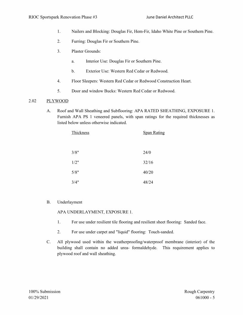
RIOC Sportspark Renovation Phase #3 June Daniel Architect PLLC
100% Submission Rough Carpentry 01/29/2021 061000 - 5
1. Nailers and Blocking: Douglas Fir, Hem-Fir, Idaho White Pine or Southern Pine.
2. Furring: Douglas Fir or Southern Pine.
3. Plaster Grounds:
a. Interior Use: Douglas Fir or Southern Pine.
b. Exterior Use: Western Red Cedar or Redwood.
4. Floor Sleepers: Western Red Cedar or Redwood Construction Heart.
5. Door and window Bucks: Western Red Cedar or Redwood.
2.02 PLYWOOD
A. Roof and Wall Sheathing and Subflooring: APA RATED SHEATHING, EXPOSURE 1. Furnish APA PS 1 veneered panels, with span ratings for the required thicknesses as listed below unless otherwise indicated.
Thickness Span Rating
3/8" 24/0
1/2" 32/16
5/8" 40/20
3/4" 48/24
B. Underlayment
APA UNDERLAYMENT, EXPOSURE 1.
1. For use under resilient tile flooring and resilient sheet flooring: Sanded face.
2. For use under carpet and "liquid" flooring: Touch-sanded.
C. All plywood used within the weatherproofing/waterproof membrane (interior) of the building shall contain no added urea- formaldehyde. This requirement applies to plywood roof and wall sheathing.

RIOC Sportspark Renovation Phase #3 June Daniel Architect PLLC
100% Submission Rough Carpentry 01/29/2021 061000 - 6
2.03 MISCELLANEOUS MATERIALS
A. Underlayment Patching Compound
Hardsetting, quicksetting type with latex or polyvinyl acetate binder.
B. Asphalt Felt
Asphalt-saturated felt, No. 15, without perforations, complying with ASTM D226.
C. Rosin Paper
Commercial, rosin-sized building paper, 0.010" thick.
D. Hardboard
PS 58, Class "Tempered, S1S, plainboard.
E. Adhesive
APA Specification AFG-01. For adhesive used on site and within the weatherproofing/waterproof membrane (interior) of the building, comply with V.O.C. requirements specified in Section G01600.
2.06 FRAMING HARDWARE
A. Fasteners and Anchoring Devices
Provide items of type, size, style, grade, and class as required for secure installation of the Work. Items shall be galvanized for exterior use. Unless shown or specified otherwise, comply with the following:
1. Nails and Staples: ASTM F1667
2. Wood Screws: FS FF-S-111D.
3. Bolts and Studs: FS FF-B-575C.
4. Nuts: FS FF-N-836E.
5. Washers: FS FF-W-92B.
6. Lag Bolts or Lag Screws: ASME/ANSI B18.2.1
7. Masonry Anchoring Devices: Expansion shields, masonry nails and drive screws: CIDS A-A-1925A, A-A-55614, A-A-55615
8. Bar or Strap Anchors: ASTM A575 carbon steel bars.

RIOC Sportspark Renovation Phase #3 June Daniel Architect PLLC
100% Submission Rough Carpentry 01/29/2021 061000 - 7
9. Wall Plugs: Corrugated type, galvanized steel, 24 USS gauge min, not less than 2" wide x 2½" deep.
10. Cross Bridging: Nailable type, galvanized steel, 16 USS gauge min, by 3/4" wide.
11. Metal Hangers and Framing Anchors: Size and type for intended use, galvanized finish, manufacturer's recommended fasteners.
12. Buck Anchors: Corrugated type, galvanized steel not lighter than 12 USS gauge min, 4" wide (except where partitions are less than 4" thick) by 8" long, punched for two 5/16" carriage bolts at buck end.
13. Sleeper Anchors: Approved type, galvanized steel not lighter than 20 USS gauge min, not less than 1¼" wide, designed to anchor into concrete not less than 1½" and permit height adjustment of sleeper.
PART 3 - EXECUTION
3.01 EXAMINATION
A. Verification of Conditions
Examine substrate and supporting structure on which rough carpentry is to be installed for defects that will adversely affect the execution and quality of the Work. Do not proceed with installation until unsatisfactory conditions are corrected.
3.02 INSTALLATION - GENERAL
A. Do not use units of material with defects which impair the quality of the Work and units which are too small to fabricate the Work with minimum joints or with optimum joint arrangement.
B. Install Work accurately to required lines and levels with members plumb and true, accurately cut and fitted and securely fastened. Closely fit rough carpentry to other associated construction.
C. Securely attach carpentry Work to substrates by anchoring and fastening as indicated, or, if not indicated, as required by the referenced standards. Select fasteners of size that will not penetrate through members where opposite side will be exposed to view or will receive finish materials. Make tight connections between members. Install fasteners without splitting wood; predrill as required. Set nail heads in exposed Work which is to be painted or stained and fill resulting holes.

RIOC Sportspark Renovation Phase #3 June Daniel Architect PLLC
100% Submission Rough Carpentry 01/29/2021 061000 - 8
3.03 WOOD NAILERS, BLOCKING, AND GROUNDS
A. Install required items where indicated and where required for support, attachment or screeding of other Work. Form to shapes indicated or required. Coordinate locations and cut and shim as required to provide items at true and level planes to receive Work to be attached. Install closure strips to nailers at all edges.
1. Attach to substrates as indicated; if not indicated, size and space fasteners as required to support applied loading. Maximum spacing of fasteners shall not exceed 16". Unless otherwise shown on the Drawings, install and secure material to non-wood construction as follows:
a. To Concrete: Attach material less than 1½" thick with screws and non-ferrous metal expansion shields. Attach materials 1½" and thicker with machine bolts and non-ferrous metal compound type anchors.
b. To Concrete Unit Masonry: Attach material to new masonry with annular ring nails driven into wall plugs where fastening occurs at joints of masonry or with special hardened steel masonry nails where fastening occurs in the masonry units. Attach material to existing masonry with machine screws and non-ferrous metal expansion shields where fastening occurs in solid portions of masonry. If fastening occurs at cells of masonry, secure material in place with toggle bolts.
c. To Brick Masonry: Attach material to new masonry with annular ring nails driven into wall plugs. Attach material to existing masonry with machine screws and non-ferrous metal expansion shields.
d. To Steel: Attach material with galvanized bolts and nuts or stainless steel machine screws tapped into the metal, as required by conditions.
e. To Non-Ferrous Metal: Attach material with stainless steel or other approved non-ferrous metal bolts and nuts or self-tapping screws, as required by conditions.
2. Counter-sink bolts and nuts flush with surfaces, unless otherwise shown. Build into masonry during installation of masonry Work. Where possible, anchor to formwork before concrete placement. Bevel both edges of members to be anchored in concrete. Shims shall be cedar shingles or redwood wedges.
3. Install permanent grounds of dressed, preservative treated, key beveled lumber not less than 1½" wide and of the thickness required to bring face of ground to exact thickness of finish material involved. Remove temporary grounds when no longer required.

RIOC Sportspark Renovation Phase #3 June Daniel Architect PLLC
100% Submission Rough Carpentry 01/29/2021 061000 - 9
4. The grounds for coat hook and bracket strips in wardrobe cabinets shall be attached to partitions with toggle bolts and to brick walls with expansion bolts before any plastering is done.
3.04 PLYWOOD SHEATHING, SUBFLOORING, AND UNDERLAYMENT
A. Comply with printed installation requirements of the APA Design/Construction Guide, for plywood application required, unless otherwise indicated.
B. Plywood Underlayment
Install underlayment just prior to installation of finish flooring. Stagger end joints between panels in relation to each other and stagger all joints in relation to substrate jointing. Allow 1/32" space between panel ends and edges for expansion. Fasten in accordance with APA recommendations. Prior to installation of finish flooring, patch damaged areas wider than 1/16". Set nails 1/16", but do not fill. Sand rough areas smooth, and uneven joints flush. Fasteners must be flush with the surface of the subfloor.
C. Wall Sheathing
Allow 1/16" spacing at panel ends and 1/8" spacing at edges.
Nail 6" o.c along panel edges and 12" o.c at intermediate supports.
D. Nails
Common.
For plywood thickness to 1/2": 6d.
For plywood thickness greater than 1/2": 8d.
3.07 WOOD FURRING
A. Install members plumb and level with closure strips at all edges. Shim with wood as required to achieve tolerance specified.
1. Fastening: Attach to substrates as indicated; if not indicated, attach material as specified for nailers and blocking.
2. Tolerance: Shim and level wood furring to a tolerance of 1/8" in 10'.
3. Furring to Receive Plywood Paneling: Unless otherwise indicated, 1" x 3" furring at 2' o.c, horizontally and vertically.
4. Furring to Receive Gypsum Drywall: Unless otherwise indicated, 1" x 2" furring at 16" oc, vertically.

RIOC Sportspark Renovation Phase #3 June Daniel Architect PLLC
100% Submission Rough Carpentry 01/29/2021 061000 - 10
3.12 ROUGH HARDWARE
A. Furnish and install all rough hardware, such as nails, bolts, buck anchors, clips, (including expansion and carriage bolts for wall seats, wardrobe brackets, etc.), and all other rough hardware required to secure the carpentry work in place, unless otherwise specified.
END OF SECTION

RIOC Sportspark Renovation Phase #3 June Daniel Architect PLLC
100% Submission Finish Carpentry 01/29/2021 062000 - 1
SECTION 062000 - FINISH CARPENTRY
PART 1 - GENERAL
1.01 DESCRIPTION OF WORK
A. Provide all finish carpentry Work as indicated on the Drawings and as specified herein.
1.02 REFERENCES
A. References and industry standards listed in this Section are applicable to the Work. Unless more restrictive criteria or differing requirements are explicitly stated in the Specifications, or mandated by governing codes or regulations, the recommendations, suggestions, and requirements described in the referenced standards shall be deemed mandatory and applicable to the Work.
1. Architectural Woodwork Institute (AWI)
Architectural Woodwork Quality Standards
2. American Society for Testing and Materials (ASTM)
E84 Standard Test Method for Surface Burning Characteristics of Building Materials
3. American National Standards Institute (ANSI)
ANSI A208.1
4. Underwriter's Laboratories, Inc. (UL)
1.03 SUBMITTALS
A. Product Data
Submit manufacturer's or supplier's product data for each product and process specified as work of this Section and incorporated into items of finish carpentry.
B. Quality Certification
Submit woodwork Manufacturer's (Fabricator's) certification, stating that fabricated woodwork complies with AWI quality grades and other requirements indicated herein.
C. Wood Treatment Data
Submit chemical treatment manufacturer's instructions for handling, storing, installation, and finish of treated material.

RIOC Sportspark Renovation Phase #3 June Daniel Architect PLLC
100% Submission Finish Carpentry 01/29/2021 062000 - 2
D. Fire-Retardant Treatment
Provide certification by treating plant that treated materials comply with requirements.
E. Shop Drawings
Submit Shop Drawings showing location of each fabricated item, dimensioned plans and elevations, large scale details and profiles, attachment devices and other components.
1. Identify woodwork item using same identification system shown on Architectural Drawings.
2. Coordinate details and cut-outs to accommodate accessories specified under other Sections.
F. Samples
1. Wood Trim: 12" length of each type and finish (e.g., base, casings, stools, aprons, chair rail, exercise barre).
2. Plywood Paneling: 12" x 12" for each type and finish.
1.04 QUALITY ASSURANCE
A. AWI Quality Standard
Comply with applicable requirements of the AWI "Architectural Woodwork Quality Standards", except where indicated otherwise.
Fabrication and Installation Qualifications
Firm which can demonstrate a minimum of 5 years of successful experience in fabricating and installing woodwork items similar in type and quality to those required for this project.
C. Submit name of firm to the Owner for approval.
E. All plywood, composite wood products and laminating adhesives used shall contain no added urea-formaldehyde.
1.05 DELIVERY, STORAGE, AND HANDLING
A. Protect woodwork during transit, delivery, storage and handling to prevent damage, soiling and deterioration.
B. Do not deliver woodwork until operations which could damage, soil or deteriorate woodwork have been completed in installation areas. If woodwork must be stored, store only in areas meeting requirements and conditions specified for installation areas.
1.06 PROJECT CONDITIONS

RIOC Sportspark Renovation Phase #3 June Daniel Architect PLLC
100% Submission Finish Carpentry 01/29/2021 062000 - 3
A. Conditioning
Woodwork Installer shall advise the Owner's Representative of temperature and humidity requirements, in writing for woodwork installation and storage areas. Do not install woodwork until required temperature and relative humidity have been stabilized.
B. Maintain temperature and humidity conditions in installation area as required to maintain moisture content of installed woodwork within 1.0 percent of optimum moisture content as follows:
1. Optimum moisture content of wood: 5-10%
2. Relative humidity required to be maintained in installation and storage areas: 25-55%
PART 2 - PRODUCT
2.01 MATERIAL
A. General
1. All interior wood finish shall be made up of thoroughly seasoned, kiln dried woods of the kinds specified.
2. All material shall be clear on all exposed faces and edges, free from checks, cracks or other blemishes that would mar the appearance of the finished wood.
3. In assembling interior woodwork, arrange so that variations in grain pattern are kept to a minimum.
4. All material shall be product of one mill.
5. All plywood and laminating adhesives used shall contain no added urea- formaldehyde.
B. Species and Grades (Lumber)
1. Plain Sawn Appalachian Red Oak, AWI Grade A1 (for transparent finish): interior wood finish throughout, except as otherwise specified or shown on Drawings.
2. Red or White Birch, AWI Grade B2, (for opaque finish): Interior window trim, all wood finish in Auditorium Cloak Rooms, Locker Rooms, Cafeterias, Lunch Room Rest Rooms, Toilets, Store Rooms, Supply Closets, all units in Medical Suite, Kitchen, Help's Locker Rooms, Receiving Room, Kindergarten Equipment Store Room.
Option: Maple, Yellow Poplar, or Basswood: AWI Grade B2.

RIOC Sportspark Renovation Phase #3 June Daniel Architect PLLC
100% Submission Finish Carpentry 01/29/2021 062000 - 4
3. White Birch, AWI Grade A1 (for transparent finish): Kindergarten, Early Childhood Rooms and Auditorium Platform.
C. Species, Grades, Types (Plywood)
1. Veneer: Oak and White Birch, as specified herein, AWI Grade A1.
2. Grain Appearance: Running Match.
3. Core: Particleboard or fiberboard, medium density M-1 grade, fire-retardant.
2.02 FABRICATION, GENERAL
A. Wood Moisture Content
Comply with requirements of referenced quality standard for moisture content of lumber at time of fabrication and for relative humidity in installation areas. (See Art. 1.07).
B. Fabricate woodwork to dimensions, profiles, and details indicated.
C. Complete fabrication, assembly, finishing, and other work before shipment to maximum extent possible. Disassemble components only as necessary for shipment and installation. Where necessary, provide ample allowance for scribing, trimming, and fitting.
D. Pre-Cut Openings
Provide woodwork with pre-cut openings, where possible, for hardware, appliances, plumbing fixtures, electrical work and similar items. Locate openings accurately and use templates or roughing-in diagrams for proper size and shape. Smooth edges of cutouts.
E. Measurements
Before fabrication of woodwork to be fitted to other construction, obtain field measurements and verify dimensions and shop drawings detail as required for accurate fit.
1. Where field measurements before fabrication would delay the project, fabricate without field measurements and provide ample borders and edges to allow for scribing and trimming of woodwork.
2.03 LUMBER THICKNESS
A. Finish thicknesses of members, and tolerances permitted:
Comply with AWI Section 3, 4.2.1.

RIOC Sportspark Renovation Phase #3 June Daniel Architect PLLC
100% Submission Finish Carpentry 01/29/2021 062000 - 5
PART 3 - EXECUTION
3.01 CONDITION OF SURFACES
A. Examine all grounds, stripping and blocking, to secure paneling and other items provided under this Section.
B. Do not install until all defects are corrected.
3.02 INSTALLATION
A. Install woodwork plumb and level without distortion.
B. Shim as necessary with concealed shims.
C. Accurately scribe and closely fit all face plates, filler strips and trim strips to irregularities of adjacent surfaces.
D. Do all Work in strict accordance with the details for the various portions of the Work.
E. For adjoining pieces of hardboard, carefully select to match the color and grain as closely as possible.
F. Interior finish
High-speed machine work, free from planing machine marks, sandpapered smooth, ready to receive paint or varnish.
G. Carefully fit woodwork and secure with finishing nails; countersink nails.
H. Do not allow kerfing on faces of trim or moldings.
I. Properly house stiles and rails into framework and properly nail and glue all parts together.
J. Miter, with miters doweled or clamped, all trim joints except window trim.
K. Install all trim, when applied to a surface less than 13 feet in length, in one length: no piecing will be accepted. Provide bevel joints, where joints are required; no butt joints will be accepted.
L. In addition to machine sanding, sand all interior woodwork by hand with 00 sandpaper to give trim a smooth surface for finishing.
3.03 APPLYING HARDWARE
A. Fasteners for Interior Finish Carpentry: Nails, screws, and other anchoring devices of type, size, material, and finish required for application indicated to provide secure attachment, concealed where possible.

RIOC Sportspark Renovation Phase #3 June Daniel Architect PLLC
100% Submission Finish Carpentry 01/29/2021 062000 - 6
1. Where finish carpentry materials are exposed in areas of high humidity, provide fasteners and anchorages with hot-dip galvanized coating complying with ASTM A153/A153M.
B. Apply all miscellaneous hardware not specified to be installed under Section 08710, Section 06410 and other Sections.
END OF SECTION

RIOC Sportspark Renovation Phase #3 June Daniel Architect PLLC
100% Submission Custom Casework 01/29/2021 064100 - 1
SECTION 064100 - CUSTOM CASEWORK
PART 1 - GENERAL 1.01 DESCRIPTION OF WORK
A. Provide wood casework and cabinets as indicated on the Drawings and as specified herein. All casework shall have wood finish except where laminate cladding is indicated on the Drawings.
1.02 REFERENCES
A. References and industry standards listed in this Section are applicable to the Work. Unless more restrictive criteria or differing requirements are explicitly stated in the Specifications, or mandated by governing codes or regulations, the recommendations, suggestions, and requirements described in the referenced standards shall be deemed mandatory and applicable to the Work.
1. Architectural Woodwork Institute (AWI):
Architectural Woodwork Quality Standards
2. American Society for Testing and Materials (ASTM)
3. American National Standards Institute (ANSI): ANSI 156.9 B43161, ANSI A208.1
4. National Electrical Manufacturers Association (NEMA):
NEMA LD3 High-Pressure Decorative Laminates
5. American Wood Preservers' Association (AWPA). Standard UC1
1.03 SUBMITTALS
A. Product Data: Submit manufacturer's product data for each product and process specified as work of this Section and incorporated into items of the casework.
B. Manufacturer’s AWI Certifications: Submit casework manufacturer's (fabricator's)
certification, stating that fabricated casework complies with AWI quality grades and other requirements indicated herein.
C. Wood Treatment Data: Submit chemical treatment manufacturer's instruction for handling,
storing, installation, and finish of treated material.
D. Fire-Retardant Treatment: Certification by treating plant stating treated material complies with AWPA specified use category UCFA standards and treatment will not bleed through specified finishes.
E. Hardware (for each type): Name, manufacturer, type, style, size, function, finish, and
information about fastenings.

RIOC Sportspark Renovation Phase #3 June Daniel Architect PLLC
100% Submission Custom Casework 01/29/2021 064100 - 2
F. Samples: Submit the following samples representative of quality to be provided in finished
work:
1. Hardwood veneer plywood.
2. Plastic laminate, 8" x 10" for each type, color, pattern and surface finish.
3. Hardware, one of each type and finish of each item to be used.
4. Counter tops and exposed shelving, 12" x 12" with wood edge and/or laminate edge as shown.
5. Stain Colors for selection
6. One Unit of Cabinet Work Each Shipment (If Requested)
G. Name of Cabinet Mfr/Fabricator of cabinetwork
1.04 QUALITY ASSURANCE
A. AWI Quality Standard: Comply with applicable requirements of the AWI "Architectural Woodwork Quality Standards", except where indicated otherwise.
B. Fabrication and Installation Qualifications: firm which can demonstrate a minimum of 5
years of successful experience in fabricating and installing casework items similar in type and quality to those required for this project.
C. Submit name of firm to the Owner for approval.
D. The Owner reserves the right to select at random one unit of cabinetwork in each shipment
and to dismantle and examine it for determination of compliance with the Specifications.
If, after examination, it is found that the unit does comply, the cost of the replacement unit will be paid for by the Owner. If, after examination, it is found that the unit does not comply, the entire shipment shall be removed from the Project Site and cabinetwork complying with the Specifications shall be provided. Expense of removal and replacement shall be borne by the Contractor.
E. Obtain each type of hardware from a single manufacturer.
F. All plywood, composite wood products and laminating adhesives used shall contain no
added urea-formaldehyde. 1.05 DELIVERY, STORAGE, AND HANDLING
A. Protect casework during transit, delivery, storage and handling to prevent damage, soiling and deterioration.

RIOC Sportspark Renovation Phase #3 June Daniel Architect PLLC
100% Submission Custom Casework 01/29/2021 064100 - 3
B. Do not deliver casework, until operations which could damage, soil or deteriorate casework have been completed in installation areas. If casework must be stored, store only in areas meeting requirements specified for installation areas.
1.06 PROJECT CONDITIONS
A. Casework Manufacturer and Installer shall advise the Owner's Representative of temperature and humidity requirements in writing for casework installation and storage areas. Do not install casework until building is enclosed, wet work and utility roughing-in are complete, and HVAC system is operating and required temperatures and relative humidity have been stabilized.
B. Maintain temperature and humidity in installation area as required to maintain moisture
content of installed woodwork within 1.0 percent of optimum moisture content as follows:
1. Optimum Moisture Content of Wood: 5-10%
2. Relative humidity required to be maintained in installation and storage areas: 25-55%
1.07 COLOR SELECTIONS
A. Stain colors and plastic laminate colors, patterns and textures: selected by the Project Architect from manufacturer’s standard colors.
PART 2 – PRODUCTS 2.01 FABRICATION, GENERAL
A. Wood Moisture Content: Comply with requirements of referenced quality standard for moisture content of lumber and plywood at time of fabrication and for relative humidity in installation areas.
B. Fabricate casework to dimensions, profiles, and details indicated with openings and
mortises precut, where possible, to receive hardware and other items and work.
C. Complete fabrication, assembly, finishing, hardware application, and other work before shipment to maximum extent possible. Disassemble components only as necessary for shipment and installation. Where necessary, provide ample allowances for scribing, trimming, and fitting.
D. Pre-Cut Openings: Provide casework with pre-cut openings, where possible, for hardware,
appliances, plumbing fixtures, electrical work and similar items. Locate openings accurately and use templates or roughing-in diagrams for proper size and shape. Smooth edges of cutouts and, where located in countertops, seal edges of cutouts with a water-resistant coating.
E. Measurements: Before fabrication of casework to be fitted to other construction, obtain
field measurements and verify dimensions and shop drawing details as required for accurate fit.

RIOC Sportspark Renovation Phase #3 June Daniel Architect PLLC
100% Submission Custom Casework 01/29/2021 064100 - 4
1. Where field measurements before fabrication would delay the project, fabricate without field measurements and provide ample borders and edges to allow for scribing and trimming of casework.
F. Cabinet work and paneling construction shall comply with the requirements of AWI
Architectural Cabinets and Paneling, Premium Grade, except where indicated herein and on the Drawings for more stringent requirements.
G. All plywood, composite wood products and laminating adhesives used shall contain no
added urea-formaldehyde. 2.02 WOOD SPECIES AND GRADES
A. Solid Wood and Hardwood Veneer Plywood
1. Where exposed to view, interior finish throughout Building, except as indicated in 2. below, and except as indicated otherwise on the Drawings: Plain Sawn Red Oak, AWI Grade A1.
2. Pre-Kindergartens, Kindergartens, Early Childhood Rooms and Auditorium
Platforms: White Birch, AWI Grade A1.
3. Plywood not exposed to view (tops and backs): AWI Grade B2.
4. Grain appearance: Running match; grain consistent for each cabinet.
5. Provide same species of veneer on both sides of plywood.
6. Shelving in Cabinets (exposed) and Backs of Open Book Shelves and Magazine Racks: Plain Sawn Red Oak, AWI Grade A1 for Oak Units; White Birch, AWI Grade A1 for Birch units. Solid wood shelving edge (Oak or Birch, to match cabinet species).
7. Shelving in Cabinets (unexposed): White or Red Birch, AWI Grade B2, with solid
wood edge (Oak or Birch, to match cabinet species). 2.03 TYPES OF PANELS
A. Particleboard core plywood: medium density particleboard core, with face and back veneers and cross bandings (5-ply). Use only for drawer sides or where covered by laminate. Not permitted for shelving.
B. Veneer Core Plywood: core of odd number of veneer plies, with face and back hardwood
veneers. Use veneer core plywood for all casework, except that other panel types are permitted for certain components where covered by plastic laminate. Use veneer core plywood, exterior grade, for all cabinet tops with sinks, and including the full sub-top beneath agglomerated quartz countertops.
2.04 TEMPERED HARDBOARD
A. Manufacturers

RIOC Sportspark Renovation Phase #3 June Daniel Architect PLLC
100% Submission Custom Casework 01/29/2021 064100 - 5
1. Masonite Corp. Towanda, PA 18848
2. Lousiana-Pacific Corp. Neenah, WI 3. Forestex Co. Division of Stimson Lumber Forest Grove, OR
B. Type: solid or perforated (holes spaced evenly at 1" o.c. in both directions, with even
borders around edges), as indicated on the Drawings.
C. Thickness: as indicated on the Drawings. 2.05 HIGH PRESSURE DECORATIVE PLASTIC LAMINATES
A. Manufacturers
1. Formica Corp.
2. Wilsonart LLC. 3. Panolam Surface Systems – Nevamar, Pionite decorative surfaces
B. Adhesives: as recommended by plastic laminate manufacturer. 2.06 ARCHITECTURAL CABINETS - LAMINATE CLAD
A. Comply with AWI requirements for Section 10 4.2.8 Laminate Clad Cabinets, Premium Grade.
B. Laminate Cladding: High pressure decorative laminate complying with the requirements of
AWI Section 4 4.2c and minimum test procedures and requirements of NEMA LD3:
1. Colors, Finishes, Patterns: as selected by the Project Architect.
2. Surfaces, Grades and Thicknesses:
a. Horizontal surfaces other than tops: HGS, nominal thickness 0.048".
b. Tops: HGS, nominal thickness 0.048".
c. Post-formed Surfaces: Horizontal HGP, nominal thickness, 0.039".
d. Post-formed Surfaces: Vertical VGP, nominal thickness, 0.028”
e. Vertical Surfaces: VGS, nominal thickness 0.028".
f. Edges: nominal thickness 0.048".

RIOC Sportspark Renovation Phase #3 June Daniel Architect PLLC
100% Submission Custom Casework 01/29/2021 064100 - 6
C. Surface Material of Panels
1. Exposed surfaces (other than edges): Grade II.
2. Semi-Exposed surfaces (other than edges): Grade III.
3. Edges: Grade II.
D. Types of Panels
See Art. 2.03.
E. Wood Laminate Grains
1. Long direction of panel, unless indicated otherwise on the Drawings.
F. Grades of Semi-exposed Components
1. Comply with AWI Section 10 4.2.8.3, Premium Grade, unless indicated otherwise on the Drawings.
G. Materials and Minimum Thickness for Cabinet Components
1. Body members: Panel: 3/4"
2. Rails: Panel or Lumber: 3/4" 3. Shelves: Veneer Core Plywood Panel: 3/4" for spans to 39" 1" for spans 39" to 48"
4. Backs: Panel: 1/2"
5. Drawer Sides: Particleboard core plywood Panel: 1/2"
6. Drawer Bottoms: Veneer Core Plywood:
For bottoms 12" wide or less: 1/4"
For bottoms 12" to 30" wide: 3/8"
For bottoms over 30" wide: 5/8"
7. Drawer Fronts: Panel: 3/4"
H. Core materials and Thickness for Hinged Cabinet Doors

RIOC Sportspark Renovation Phase #3 June Daniel Architect PLLC
100% Submission Custom Casework 01/29/2021 064100 - 7
1. Particleboard core plywood: Thickness dependent on size of door For doors 30" width, 60" height: 3/4"
For doors 36" width, 72" height: 1"
I. Edge Treatment of Exposed and Semi-exposed Components
1. Body Members and Shelves: Match face laminate
2. Doors: Match face laminate. 3. All edges: HDPL, banded; pressure-glued.
J. Construction: Comply with the following AWI requirements:
1. Drawer Construction: AWI Section 10 4.4.26.2.
2. Joinery and Case Body Member Fastening: Comply with AWI Section 10 4.4
Standards for Premium Grade. 2.07 CABINET TOPS
A. Comply with the requirements of AWI Section 10 4.4.9, for Premium Grade.
B. High Pressure Decorative Laminate Tops
Width: if exceeds 60", shop assembled. Length in one Piece: 12' Thickness of Top: 3/4" minimum. Balancing Sheet Requirements: Standard 0.02" backup sheet wherever unsupported area exceeds 4 sq. ft. and core is 3/4" thick; 6 sq. ft. and core is 1" thick; 8 sq. ft. and core is 11/8" thick or thicker.
2.08 FIXED PANELS
A. Wood paneling areas adjacent to cabinetwork and paneling at walls in other areas:
1. Comply with the requirements of AWI Section 6 Premium Grade.
2. Wood Species: Plain Sawn Red Oak, AWI Grade A1. 2.09 CASEWORK TYPES
A. Sink Countertops 1. Provide Countertops as indicated on the Drawings: 2. High-Pressure Decorative Laminate
RIOC Sportspark Renovation Phase #3 June Daniel Architect PLLC
100% Submission Custom Casework 01/29/2021 064100 - 8
3. Colors, Patterns, and Finishes: Provide materials and products that result in colors
and textures of exposed laminate surfaces complying with the following requirements:
a. As selected by Architect from manufacturer's full range.
4. Edge Treatment: edge for transparent finish matching wood species used on
cabinet surfaces 5. Core Material: a. Sink Countertop: Exterior-grade plywood
b. Security Desk: Particleboard
6. Backer Sheet: Provide plastic-laminate backer sheet, Grade BKL, on underside of
countertop substrate.
7. Supports: a. Sink Countertop: Minimum 3/4" exterior-grade plywood with plastic
laminate faced sides and exposed hardwood edge or as indicated on drawings.
8. Grommets for Cable Passage through Countertops 2” molded plastic grommets and
matching plastic caps with slot for wire passage. a. Product: Subject to compliance with requirements, provide grommets by
Doug Mockett & Company, Inc. or equal
2.10 HARDWARE - GENERAL
A. Manufacturers
1. Cylinders for Drawers, and Book cabinets
a. Sargent b. Corbin Russwin
2. Cabinet Hardware
a. Ives b. Stanley
3. Door Pulls
a. Ives b. Stanley

RIOC Sportspark Renovation Phase #3 June Daniel Architect PLLC
100% Submission Custom Casework 01/29/2021 064100 - 9
4. Drawer Pulls
a. Ives b. Stanley
5. Drawer Slides
a. Grant b. Knape & Vogt
6. Hinges
a. Ives b. Stanley c. Lawrence d. McKinney
B. Screws
1. Secure hardware with suitable screws and bolts of same material and finish as
hardware items unless otherwise specified. Provide Phillips head screws unless otherwise indicated.
2. Manufacturer of each hardware item shall provide the fastenings required for the
installation of that item.
C. Hardware Finish
Hardware finishes including the following shall comply with requirements of ANSI/BHMA standards:
BHMA Code Description
Base material U.S. Standards equivalent
605 Bright Brass
Brass US3
625 Bright Chromium Brass or Bronze US26 626 Satin Chromium Brass/Bronze base US26D 629 Bright Stainless Steel Stainless steel US32 630 Satin Stainless Steel Stainless steel US32D
2.11 HARDWARE REQUIREMENTS
A. Pin Tumbler Cylinder Lock for Drawers in Tables, Book Cabinets, Bookcases, Supply
Cabinets, and other locations indicated: Bronze. B. Pin Tumbler Cylinder Lock for Doors in Book Cabinets, Bookcases, Supply Cabinets, and
other locations indicated.

RIOC Sportspark Renovation Phase #3 June Daniel Architect PLLC
100% Submission Custom Casework 01/29/2021 064100 - 10
Cast bronze lock, size 2" x 15/8", with 3/16" x 7/8" bolt of not less than 1" throw, Sargent 1655.
Lock for Sliding Doors shall be cylinder push lock.
C. Cylinders Cylinders of locks shall be of proper length to fit doors or drawers for which they are
intended. Cylinders shall be solid brass with common standard diameter rotating plug. The keyway shall be paracentric type of single section with seven pins or multiple (four or more) sections with six pins capable of being masterkeyed and grand masterkeyed as specified without duplications or interchanges.
D. Magnetic Catches For doors over 3’-0” in height: Aluminum Case. Dual triple pole with self-aligning
magnets. Conform to ANSI 156.9 B43161. Ives Heavy Duty Magnetic Catch No. 327. For doors 3’-0” and under in height: Aluminum Case. Dual double pole with self-aligning
magnets. Conform to ANSI 156.9 B43161. Ives Heavy Duty Magnetic Catch No. 326.
E. Elbow Catch on Inactive leaf of Doors Under 3'-0" in Height Cast brass elbow catch with spring on plate not less than 2½" x 1", strike plate not less than
1½" x 1/2", six screws. Conform to ANSI 156.9.
F. Hinges for laminate clad doors with particleboard cores Provide Blum Modul Series hinges as manufactured by Julius Blum Inc. or equivalent by
Sugatsune America Inc. Provide quantity of hinges for door size and weight as recommended by the hinge manufacturer, as a minimum. Provide at least 3 hinges for doors less than 5'-0" and at least 4 hinges for doors between 5'-0" and 6'-0".
G. Drawer Pulls Approved cast-bronze, secured by two concealed screws. Clear finger space not less than
11/16" x 25/8", and 41/8" over all. Weight not less than 2 ounces. Unless otherwise specified, provide two pulls for drawers 20" wide or over and one pull for drawer less than 20" wide.
H. Slides: Powder coated metal slides, 100 lb. rating, bottom mount with self-closing action.
All drawers to open to three-fourths of the drawer length. I. Cabinet Shelf Rests Rests shall be of gray-plate metal supported by gray plate metal standards. Four (4) rests
for each shelf. Provide rests for adjustable wood and metal shelves in cases and cabinets indicated on Drawings.

RIOC Sportspark Renovation Phase #3 June Daniel Architect PLLC
100% Submission Custom Casework 01/29/2021 064100 - 11
2.12 INSTALLATION MATERIALS
A. Anchors: Select material, type, size, and finish required for each substrate for secure anchorage.
2.13 FACTORY FINISHING
A. Finish for Wood Cabinetwork: Comply with AWI Section 5- Factory Finishing System #11 Catalyzed Polyurethanes, Satin-medium rubbed sheen, as follows for Premium grade:
Oak: Filler, washcoat, stain, sealer, sand (220 grit stearated paper), topcoat.
Birch and Maple (and other closed grain woods): washcoat, stain, sealer, sand (220 grit stearated paper) topcoat.
2.14 KEYING FOR CABINETWORK
A. All casework/millwork – doors and drawers shall have locks and keys.
B. All casework/millwork in a room shall be individually keyed, mastered by room and grand
mastered.
C. Provide three (3) keys for each lock and three (3) master keys. PART 3 - EXECUTION 3.01 PREPARATION
A. Examine all areas to receive Work of this Section and correct conditions as required to accommodate the Work.
B. Do not deliver and install Work of this Section until wet work such as plastering, painting
and other finishes is completed; the HVAC system shall be operating and maintaining proper temperature and humidity conditions.
C. Condition cabinetwork and paneling to the average ambient humidity conditions prior to
installation.
D. Verify the location and condition of concrete inserts, and other built-in anchoring devices. 3.02 INSTALLATION
A. Install cabinetwork and paneling plumb, true, level and without distortion. Shim as needed with concealed wood or hard plastic shims.
Tolerances: 1/8" in 8'-0" for plumb and level (including tops); allow no variation in flushness of adjoining surfaces.

RIOC Sportspark Renovation Phase #3 June Daniel Architect PLLC
100% Submission Custom Casework 01/29/2021 064100 - 12
B. Scribe and cut cabinets, paneling, and tops to fit adjoining Work. Refinish cut surfaces to match adjacent surfaces; repair damaged finishes.
C. Provide filler strips; trim strips to irregularities of adjacent surfaces.
D. Secure and anchor fixed cabinetwork to substrates with concealed devices and fasteners of
sufficient sizes and strengths to support fully-loaded cabinets.
E. Anchor tops to cabinets and supports with concealed fasteners.
F. Full sub-tops for quartz agglomerate sink counters shall be flat, level, and completely supported.
G. Secure paneling to substrates or supports with concealed fasteners, where possible; where
nails are required, use countersunk finishing nails.
3.03 HARDWARE INSTALLATION
A. Secure hardware with screws, bolts and fasteners of the proper sizes, with finish to match hardware.
B. Secure hardware to metal with suitable tap screws.
C. Shop install hardware.
3.04 ADJUSTMENT, CLEANING, FINISHING, AND PROTECTION
A. Adjust cabinetwork units as required for proper and uniform appearance.
B. Clean and lubricate hardware; adjust hardware for proper operation.
C. Clean woodwork and glasswork on both exterior and interior surfaces.
D. Touch-up shop-applied finishes where damaged or soiled, to obtain a finished appearance to match that of adjacent surfaces. If not possible to obtain a suitable finish, provide a new surface or component.
3.05 CLEANING AND ADJUSTING
A. Clean hardware items thoroughly and adjust for proper operation. 3.06 KEY OPERATION AND INSPECTION
A. Upon completion of the building and after locks have been secured in proper positions, keys belonging thereto shall be fitted and made to work freely in respective locks in the presence of the Owner's Representative.
END OF SECTION

RIOC Sportspark Renovation Phase #3 June Daniel Architect PLLC
100% Submission Metal Composite Material Wall Panel 01/29/2021 074200 - 1
SECTION 074200 - METAL COMPOSITE MATERIAL WALL PANELS PART 1 - GENERAL
1.01 RELATED DOCUMENTS
A. Drawings and general provisions of the Contract, including General and Supplementary Conditions and Division 01 Specification Sections, apply to this Section.
1.02 SUMMARY
A. Section includes MCM wall panels.
1.03 DEFINITIONS
A. PER: Pressure equalized rainscreen system; rainscreen system designed for no water intrusion with equal pressure between interior system cavity and outside cladding barrier.
1.04 PREINSTALLATION MEETINGS
A. Preinstallation Conference: Conduct conference at Project site.
1. Meet with Owner, Architect, Owner's insurer if applicable, MCM panel Fabricator and Installer, MCM sheet manufacturer's representative, structural-support Installer, and installers whose work interfaces with or affects MCM panels, including installers of doors, windows, and louvers.
2. Review and finalize construction schedule and verify availability of materials, Installer's personnel, equipment, and facilities needed to make progress and avoid delays.
3. Review methods and procedures related to MCM panel installation, including manufacturer's written instructions.
4. Examine support conditions for compliance with requirements, including alignment between and attachment to structural members.
5. Review flashings, special siding details, wall penetrations, openings, and condition of other construction that affect MCM panels.
6. Review governing regulations and requirements for insurance, certificates, and tests and inspections if applicable.
7. Review temporary protection requirements for MCM panel assembly during and after installation.
8. Review procedures for repair of panels damaged after installation. 9. Document proceedings, including corrective measures and actions required, and furnish
copy of record to each participant.

RIOC Sportspark Renovation Phase #3 June Daniel Architect PLLC
100% Submission Metal Composite Material Wall Panel 01/29/2021 074200 - 2
1.05 ACTION SUBMITTALS
A. Product Data: For each type of product.
1. Include construction details, material descriptions, dimensions of individual components and profiles, and finishes for each type of panel and accessory.
B. Shop Drawings:
1. Include fabrication and installation layouts of MCM panels; details of edge conditions, joints, panel profiles, corners, anchorages, attachment assembly, trim, flashings, closures, and accessories; and special details.
2. Accessories: Include details of the flashing, trim and anchorage, at a scale of not less than 1-1/2 inches per 12 inches.
C. Samples for Initial Selection: For each type of MCM panel indicated with factory-applied color finishes.
1. Include similar Samples of trim and accessories involving color selection.
D. Samples for Verification: For each type of exposed finish required, prepared on Samples of size indicated below.
1. MCM Panels: 12 inches long by actual panel width. Include fasteners, closures, and other MCM panel accessories. Submit custom color samples in paint manufacturer's standard size.
1.06 INFORMATIONAL SUBMITTALS
A. Qualification Data: For Installer.
B. Product Test Reports: For each product, tests performed by a qualified testing agency.
1. MCM Manufacturer's Material Test Reports: Certified test reports showing compliance with specific performance or third-party listing documenting compliance to comparable code sections IBC 1407.14 and IBC 1703.5.
2. MCM System Fabricator's Certified System Tests Reports: Certified system test reports showing system compliance with specific performance or third-party listing documenting compliance code section. Base performance requirements on MCM system type provided. a. PER System: Tested to AAMA 508.
C. Field quality-control reports.
D. Sample Warranties: For special warranties.

RIOC Sportspark Renovation Phase #3 June Daniel Architect PLLC
100% Submission Metal Composite Material Wall Panel 01/29/2021 074200 - 3
1.07 CLOSEOUT SUBMITTALS
A. Maintenance Data: For MCM panels to include in maintenance manuals.
1.08 QUALITY ASSURANCE
A. Installer Qualifications: An entity that employs installers and supervisors who are trained and approved by MCM Fabricator.
B. Mockups: Build mockups to verify selections made under Sample submittals and to demonstrate aesthetic effects and set quality standards for MCM fabrication and installation.
1. Build mockup of typical MCM panel assembly as shown on Drawings, including corner, supports, attachments, and accessories.
2. Water-Spray Test: Conduct water-spray test of mockup of MCM panel assembly, testing for water penetration in accordance with AAMA 501.2.
3. Approval of mockups does not constitute approval of deviations from the Contract Documents contained in mockups unless Architect specifically approves such deviations in writing
4. Subject to compliance with requirements, approved mockups may become part of the completed Work if undisturbed at time of Substantial Completion.
1.09 DELIVERY, STORAGE, AND HANDLING
A. Deliver components, MCM panels, and other manufactured items so as not to be damaged or deformed. Package MCM panels for protection during transportation and handling.
B. Unload, store, and erect MCM panels in a manner to prevent bending, warping, twisting, and surface damage.
C. Stack MCM panels on platforms or pallets, covered with suitable weathertight and ventilated covering. Store MCM panels to ensure dryness, with positive slope for drainage of water. Do not store MCM panels in contact with other materials that might cause staining, denting, or other surface damage.
D. Retain strippable protective covering on MCM panels during installation.
1.10 FIELD CONDITIONS
A. Weather Limitations: Proceed with installation only when existing and forecasted weather conditions permit assembly of MCM panels to be performed in accordance with manufacturers' written instructions and warranty requirements.
RIOC Sportspark Renovation Phase #3 June Daniel Architect PLLC
100% Submission Metal Composite Material Wall Panel 01/29/2021 074200 - 4
1.11 COORDINATION
A. Coordinate MCM panel installation with rain drainage work, flashing, trim, construction of soffits, and other adjoining work to provide a leakproof, secure, and noncorrosive installation.
1.12 WARRANTY
A. Warranty on Panel Material: Manufacturer's standard form in which manufacturer agrees to replace MCM that fails within specified warranty period.
1. Warranty Period: Five years from date of Substantial Completion.
B. Special Warranty on Panel Finishes: Manufacturer's standard form in which manufacturer agrees to repair finish or replace MCM panels that show evidence of deterioration of factory-applied finishes within specified warranty period.
1. Finish Warranty Period: 20 years from date of Substantial Completion.
2 PRODUCTS
2.01 PERFORMANCE REQUIREMENTS
A. Structural Performance: Provide MCM panel systems capable of withstanding the effects of the following loads, based on testing in accordance with ASTM E330:
1. Wind Loads: 30 PSF 2. Other Design Loads: As indicated on Drawings. 3. Deflection Limits: For wind loads, no greater than 1/240
B. Air Infiltration: Air leakage of not more than 0.06 cfm/sq. ft. of wall area when tested in accordance with ASTM E283 at the following test-pressure difference:
1. Test-Pressure Difference: 6.24 lbf/sq. ft.
C. Water Penetration under Static Pressure: No water penetration to room side of assembly when tested for 15 minutes in accordance with ASTM E331 at the following test-pressure difference:
1. Test-Pressure Difference: 6.24 lbf/sq. ft.
D. Thermal Movements: Locate expansion and contraction points to allow for free and noiseless thermal movements from surface temperature changes.
1. Temperature Change (Range): minus 20 deg F to 180 deg F, material surfaces.
E. Fire Propagation Characteristics: MCM wall assembly passes NFPA 285 testing.

RIOC Sportspark Renovation Phase #3 June Daniel Architect PLLC
100% Submission Metal Composite Material Wall Panel 01/29/2021 074200 - 5
2.02 MANUFACTURER - MCM WALL PANELS
A. MCM Wall Panel Systems: Provide factory-formed and -assembled, MCM wall panels fabricated from two metal facings that are bonded to a solid, extruded thermoplastic core; formed into profile for installation method indicated. Include attachment assembly components , panel stiffeners and accessories required for weathertight system.
1. Basis-of-Design Product: Subject to compliance with requirements, provide ALUCOBOND®; 3A Composites USA Inc.; ALUCOBOND® PLUS or comparable product by one of the following:
1. Arconic Architectural Products (USA). 2. Mitsubishi Chemical Composites
2. Or Approved Equal.
B. Aluminum-Faced Composite Wall Panels Formed with 0.040-inch- thick, anodized aluminum sheet facings.
1. Panel Thickness: 0.157 inch 2. Core: Standard
a. Exterior Finish: clear anodized
b. Color: Native Copper Mettalic
3. Peel Strength: 22.5 in-lb/in. when tested for bond integrity in accordance with ASTM D1781.
4. Fire Performance: Flame spread less than 25 and smoke developed less than 450, in accordance with ASTM E84.
C. Attachment Assembly Components: Formed from extruded aluminum material compatible with panel facing.
2.03 MISCELLANEOUS MATERIALS A. Miscellaneous Metal Subframing and Furring: ASTM C645, cold-formed, metallic-coated steel
sheet ASTM A653/A653M, G90 coating designation or ASTM A792/A792M, Class AZ50 aluminum-zinc-alloy coating designation unless otherwise indicated. Provide Fabricator's standard sections as required for support and alignment of MCM panel system.
B. Panel Accessories: Provide components required for a complete, weathertight panel system including trim, copings, fasciae, mullions, sills, corner units, clips, flashings, sealants, gaskets, fillers, closure strips, and similar items. Match material and finish of MCM panels unless otherwise indicated.
C. Flashing and Trim: Provide flashing and trim formed from same material as MCM panels as
required to seal against weather and to provide finished appearance. Locations include, but are

RIOC Sportspark Renovation Phase #3 June Daniel Architect PLLC
100% Submission Metal Composite Material Wall Panel 01/29/2021 074200 - 6
not limited to, bases, drips, sills, jambs, corners, endwalls, framed openings, rakes, fasciae, parapet caps, soffits, reveals, and fillers. Finish flashing and trim with same finish system as adjacent MCM panels.
1. Basis-of-Design Product: Subject to compliance th requirements, provide ALUCOBOND®; 3A Composites USA Inc.; ALUCOBOND® Axcent™ Trim or comparable product by one of the following:
a. Arconic Architectural Products (USA). b. Mitsubishi Chemical Composites.
2. Aluminum Trim: Formed with 0.040-inch thick, coil-coated aluminum sheet facings. a. Color: Native Copper Mettalic
3. Or Approved Equal.
D. Panel Fasteners: Self-tapping screws designed to withstand design loads. Provide exposed fasteners with heads matching color of MCM panels by means of plastic caps or factory-applied coating. Provide EPDM or PVC sealing washers for exposed fasteners.
E. Panel Sealants: ASTM C920; elastomeric polyurethane or silicone sealant; of type, grade, class, and use classifications required to seal joints in MCM panels and remain weathertight; and as recommended in writing by MCM panel manufacturer.
2.04 FABRICATION
A. General: Fabricate and finish MCM panels and accessories at the factory, by manufacturer's standard procedures and processes, as necessary to fulfill indicated performance requirements demonstrated by laboratory testing. Comply with indicated profiles and with dimensional and structural requirements.
B. Fabricate MCM panel joints with factory-installed captive gaskets or separator strips that provide a weathertight seal and prevent metal-to-metal contact, and that minimize noise from movements.
C. Sheet Metal Flashing and Trim: Fabricate flashing and trim to comply with manufacturer's recommendations or recommendations in SMACNA's "Architectural Sheet Metal Manual" that apply to design, dimensions, metal, and other characteristics of item indicated.
1. Form exposed sheet metal accessories that are without excessive oil canning, buckling, and tool marks and that are true to line and levels indicated, with exposed edges folded back to form hems.
2. Seams for Aluminum: Fabricate nonmoving seams with flat-lock seams. Form seams and seal with epoxy seam sealer. Rivet joints for additional strength.
3. Seams for Other Than Aluminum: Fabricate nonmoving seams in accessories with flat-lock seams. Tin edges to be seamed, form seams, and solder.
4. Sealed Joints: Form non-expansion, but movable, joints in metal to accommodate sealant and to comply with SMACNA standards.
5. Conceal fasteners and expansion provisions where possible. Exposed fasteners are not allowed on faces of accessories exposed to view.

RIOC Sportspark Renovation Phase #3 June Daniel Architect PLLC
100% Submission Metal Composite Material Wall Panel 01/29/2021 074200 - 7
6. Fabricate cleats and attachment devices from same material as accessory being anchored or from compatible, noncorrosive metal recommended in writing by metal panel manufacturer.
a.Size: As recommended by SMACNA's "Architectural Sheet Metal Manual" or metal wall panel manufacturer for application but not less than thickness of metal being secured.
2.05 FINISHES
A. Protect mechanical and painted finishes on exposed surfaces from damage by applying a strippable, temporary protective covering before shipping.
B. Appearance of Finished Work: Variations in appearance of abutting or adjacent pieces are acceptable if they are within one-half of the range of approved Samples. Noticeable variations in same piece are not acceptable. Variations in appearance of other components are acceptable if they are within the range of approved Samples and are assembled or installed to minimize contrast.
C. Aluminum Panels and Accessories:
1. Exposed Anodized Finish:
a. Clear Anodic Finish: AAMA 611, AA-M12C22A41, Class I, 0.018 mm or thicker.
PART 3 - EXECUTION
3.01 EXAMINATION
A. Examine substrates, areas, and conditions, with Installer present, for compliance with requirements for installation tolerances, MCM panel supports, and other conditions affecting performance of the Work.
1. Examine wall framing to verify that girts, angles, channels, studs, and other structural panel support members and anchorage have been installed within alignment tolerances required by MCM wall panel manufacturer.
2. Examine wall sheathing to verify that sheathing joints are supported by framing or blocking and that installation is within flatness tolerances required by MCM wall panel manufacturer.
a. Verify that air- or water-resistive barriers have been installed over sheathing or backing substrate to prevent air infiltration or water penetration.
B. Examine roughing-in for components and assemblies penetrating MCM panels to verify actual locations of penetrations relative to seam locations of MCM panels before installation.

RIOC Sportspark Renovation Phase #3 June Daniel Architect PLLC
100% Submission Metal Composite Material Wall Panel 01/29/2021 074200 - 8
C. Proceed with installation only after unsatisfactory conditions have been corrected.
3.02 PREPARATION
D. Miscellaneous Supports: Install subframing, furring, and other miscellaneous panel support members and anchorages in accordance with ASTM C754 and MCM panel manufacturer's written recommendations.
3.03 MCM PANEL INSTALLATION
E. General: Install MCM panels in accordance with Fabricator's written instructions in orientation, sizes, and locations indicated on Drawings. Install panels perpendicular to supports unless otherwise indicated. Anchor MCM panels and other components of the Work securely in place, with provisions for thermal and structural movement.
1. Shim or otherwise plumb substrates receiving MCM panels. 2. Flash and seal MCM panels at perimeter of all openings. Fasten with self-tapping screws.
Do not begin installation until air- or water-resistive barriers and flashings that will be concealed by MCM panels are installed.
3. Install screw fasteners in predrilled holes. 4. Locate and space fastenings in uniform vertical and horizontal alignment. 5. Install flashing and trim as MCM panel work proceeds. 6. Locate panel splices over, but not attached to, structural supports. Stagger panel splices
and end laps to avoid a four-panel lap splice condition. 7. Align bottoms of MCM panels and fasten with blind rivets, bolts, or self-tapping screws.
Fasten flashings and trim around openings and similar elements with self-tapping screws. 8. Provide weathertight escutcheons for pipe- and conduit-penetrating panels.
F. Fasteners:
1. Aluminum Panels: Use aluminum or stainless steel fasteners for surfaces exposed to the exterior; use aluminum or galvanized-steel fasteners for surfaces exposed to the interior.
G. Metal Protection: Where dissimilar metals contact each other or corrosive substrates, protect against galvanic action as recommended in writing by MCM panel manufacturer.
H. Attachment Assembly, General: Install attachment assembly required to support MCM wall panels and to provide a complete weathertight wall system, including subgirts, perimeter extrusions, tracks, drainage channels, panel clips, and anchor channels.
1. Include attachment to supports, panel-to-panel joinery, panel-to-dissimilar-material joinery, and panel-system joint seals.
I. Panel Installation: Attach MCM wall panels to supports at locations, spacings, and with fasteners recommended by Fabricator to achieve performance requirements specified.
J. PER Installation: Install using Fabricator's standard assembly with vertical channel that provides support and secondary drainage assembly, draining at base of wall. Notch vertical

RIOC Sportspark Renovation Phase #3 June Daniel Architect PLLC
100% Submission Metal Composite Material Wall Panel 01/29/2021 074200 - 9
channel to receive support pins. Install vertical channels supported by channel brackets or adjuster angles and at locations, spacings, and with fasteners recommended by manufacturer. Attach MCM wall panels by inserting horizontal support pins into notches in vertical channels and into flanges of panels. Leave horizontal and vertical joints with open reveal.
1. Track-Support Installation: Install support assembly at locations, spacings, and with fasteners recommended by Fabricator. Use Fabricator's standard horizontal tracks and vertical drain channels that provide support and secondary drainage assembly, draining to the exterior at horizontal joints through drain tube. Attach MCM wall panels to tracks by interlocking panel edges with Fabricator's standard "T" clips.
2. Panel Installation:
a. Attach routed-and-returned flanges of wall panels to perimeter extrusions with Fabricator's standard fasteners.
b. Install wall panels to allow individual panels to "free float" and be installed and removed without disturbing adjacent panels.
3. Joint Sealing: Seal all joints in accordance with AAMA 508. Do not apply sealants to joints unless indicated.
K. Accessory Installation: Install accessories with positive anchorage to building and weathertight mounting, and provide for thermal expansion. Coordinate installation with flashings and other components.
1. Install components required for a complete MCM panel assembly including trim, copings, corners, seam covers, flashings, sealants, gaskets, fillers, closure strips, and similar items. Provide types indicated by MCM panel Fabricator; or, if not indicated, provide types recommended in writing by MCM system Fabricator.
L. Flashing and Trim: Comply with performance requirements, manufacturer's written installation instructions, or SMACNA's "Architectural Sheet Metal Manual." Provide concealed fasteners where possible, and set units true to line and level as indicated. Install work with laps, joints, and seams that are permanently watertight.
1. Install exposed flashing and trim that is without buckling and tool marks and that is true to line and levels indicated, with exposed edges folded back to form hems. Install sheet metal flashing and trim to fit substrates and to result in waterproof performance.
3.04 ERECTION TOLERANCES
M. Site Verifications of Conditions:
1. Verify conditions of substrate previously installed under other Sections are acceptable for the MCM system installation. Provide documentation indicating detrimental conditions to the MCM system performance.
2. Once conditions are verified, MCM system installation tolerances are as follows:

RIOC Sportspark Renovation Phase #3 June Daniel Architect PLLC
100% Submission Metal Composite Material Wall Panel 01/29/2021 074200 - 10
a. Shim and align MCM wall panel units within installed tolerance of 1/4 inch in 20, non-accumulative, on level, plumb, and location lines as indicated, and within 1/8-inch offset of adjoining faces and of alignment of matching profiles.
3.05 FIELD QUALITY CONTROL
A. Testing Agency: Owner will engage qualified independent testing agency to perform field tests and inspections.
B. Water-Spray Test: After installation, test area of assembly shown on Drawings for water penetration in accordance with AAMA 501.2.
C. Fabricator Fabricator's Field Service: Engage a factory-authorized service representative to test and inspect completed MCM wall panel installation, including accessories.
D. MCM wall panels will be considered defective if they do not pass test and inspections.
E. Additional tests and inspections, at Contractor's expense, are performed to determine compliance of replaced or additional work with specified requirements.
F. Prepare test and inspection reports.
3.06 CLEANING AND PROTECTION
A. Remove temporary protective coverings and strippable films, if any, as MCM panels are installed, unless otherwise indicated in manufacturer's written installation instructions. On completion of MCM panel installation, clean finished surfaces as recommended by MCM panel manufacturer. Maintain in a clean condition during construction.
B. After MCM panel installation, clear weep holes and drainage channels of obstructions, dirt, and sealant.
C. Replace MCM panels that have been damaged or have deteriorated beyond successful repair by finish touchup or similar minor repair procedures.
END OF SECTION

RIOC Sportspark Renovation Phase #3 June Daniel Architect PLLC
100% Submission Roof Flashing and Related Roof Repair Work 01/29/2021 075200 - 1
SECTION 075200 - ROOF FLASHING AND RELATED ROOF REPAIR WORK
PART 1 GENERAL 1.01 DESCRIPTION OF WORK
A. The Work of this Section consists of the following: 1. SBS Modified Bitumen Roof and repairs to an existing warranted or unwarranted
roof system including but not limited to pipe and duct penetrations, minor roof membrane repairs and installation of equipment curbs and rails.
2. The furnishing and installation of the following items:
a. Premanufactured Metal Curbs b. Cants c. Roof membranes and flashings
B. The Contractor has the option of providing a hot-applied system or a cold-applied system.
However, for warranted roofs approval is dependant on the manufacturer of the roof. 1.02 REFERENCES A. References and industry standards listed in this Section are applicable to the Work.
Unless more restrictive criteria or differing requirements are explicitly stated in the Specifications, or mandated by governing codes or regulations, the recommendations, suggestions, and requirements described in the referenced standards shall be deemed mandatory and applicable to the Work.
B. American Society for Testing and Materials (ASTM).
C. Underwriters Laboratories, Inc. (UL).
D. National Roofing Contractors Association (NRCA).
E. Thermal Insulation Manufacturers Association (TIMA).
F. Federal Specifications (FS)
G. Factory Mutual System (FMS)
H. United States Environmental Protection Agency (EPA)
1.03 SUBMITTALS A. Product Data: Catalog sheets, specifications, and installation instructions, for each
material specified or shown on drawing, except for the following: 1. Cants. 2. Wood nailers. 3. Gravel/crushed stone.

RIOC Sportspark Renovation Phase #3 June Daniel Architect PLLC
100% Submission Roof Flashing and Related Roof Repair Work 01/29/2021 075200 - 2
B. Applicators Certification:
1. For Unwarranted Roof Systems; submit a letter certifying that the job foreman or crew chief and at least one other member of the roofing crew have installed at least 3 built-up roof systems.
2. Material Certification: Letter from the existing roof system manufacturer
certifying that the materials used for the Work of this Section are approved for use with the existing system.
C. Contract Closeout Submittals
1. Contractor’s 2-year guarantee
2. For warranted systems, letter from manufacturer that the Work of this Section has not voided the existing warranty.
1.04 QUALITY ASSURANCE
A. Roofing Installation Qualifications
1. Roofing Firm Qualifications
a. Installation of a minimum of ten built-up roofing systems of 3-ply (or greater) membranes.
(List last five such jobs, including address, type of system and number of
plies, if applicable, square footage, date installed and owner/agent with whom contracted).
b. In continuous operation of installing such roofing systems for five years
or more.
c. Certified installer for nationally recognized roofing materials manufacturer.
B. Fire Department Regulations
Equipment and fuel shall meet the requirements of the New York State. Hot roof kettles may not be placed on the roof.
1.05 DELIVERY, STORAGE, AND HANDLING
A. Delivery: Deliver materials to the site in the manufacturer's labeled, unbroken containers.
B. Storage and Handling: Store materials in a dry, well ventilated place protected from the
weather.

RIOC Sportspark Renovation Phase #3 June Daniel Architect PLLC
100% Submission Roof Flashing and Related Roof Repair Work 01/29/2021 075200 - 3
1. Volatile liquids shall be stored in a separate storage building or trailer, or
removed from the Site at the end of each work day. 2. Store volatile liquids at temperatures recommended by the manufacturer. 3. Store adhesives at temperatures between 60°F and 80°F. 1.06 PROJECT CONDITIONS
A. Do not execute the Work of this section unless the Owner’s Representative is present, or unless the Representative directs that the Work be performed during the Representative's absence.
B. Temperature
Do not apply built-up roofing when the deck or air temperature is below 40oF.
C. Do not execute the Work of this Section unless the substrate is dry, and free from debris
and dust.
D. Moisture Protection
1. Cover, seal or otherwise protect the roof and flashings so that water cannot accumulate or flow under completed portions. When and where necessary to accomplish this, provide temporary water cut-offs in accordance with the membrane manufacturer's written specifications.
2. Limit the removal of existing materials to areas that can be completely re-roofed
or temporarily protected within the same day. 1.07 GUARANTEE AND WARRANTY
A. Contractor's Guarantee
Two year written guarantee covering defects in materials and/or workmanship. Performance Bond shall be for the entire two-year period. Also includes repair to all ancillary areas damaged due to leaks.
B. Manufacturer’s Warranty
Roofs under warranty shall have work done under the auspices of the roof manufacturer holding such warranty to maintain the existing warranty.
PART 2 PRODUCTS 2.01 MANUFACTURERS
A. Asphalt Primer and Asphalt

RIOC Sportspark Renovation Phase #3 June Daniel Architect PLLC
100% Submission Roof Flashing and Related Roof Repair Work 01/29/2021 075200 - 4
1. GAF Building Materials Corp., Wayne, NJ.
2. Johns Manville, Denver, CO.
3. CertainTeed Corporation, Valley Forge, PA 4. Trumbull/Owens Corning, Toledo, OH
B. Primer for cold repair system
1. Johns Manville PermaFlash™ Primer C. Base Sheet
1. GAF GAFGLAS #75 Base sheet.
2. Johns Manville GlasBase. 3. CertainTeed Glasbase Base Sheet 4. Firestone MB Base M.
D. Vent Base Sheet
1. GAF GAFGLAS Stratavent Eliminator Base Sheet.
2. Johns Manville Ventsulation. 3. CertainTeed Channel Vent Base Sheet 4. Firestone Venting Base
E. Ply Sheets, Vapor Barrier and Cover Strip
1. GAF GAFGLAS FlexPly 6.
2. Johns Manville GlasPly Premier. 3. CertainTeed FlintGlas Premium Ply Sheet Type VI.
4. Firestone Ply VI M.
F. Granule Surfaced Modified Bitumen Roofing Membrane Cap Sheet
1. White cap sheet a. GAF Ruberoid EnergyCap SBS 30 FR. b. Johns Manville Dynaglas FR CR
RIOC Sportspark Renovation Phase #3 June Daniel Architect PLLC
100% Submission Roof Flashing and Related Roof Repair Work 01/29/2021 075200 - 5
c. CertainTeed Flintlastic FR-P CoolStar
G. Modified Bitumen Base sheet 1. Johns Manville DynaBase Base sheet.
H. Insulation
1. Composite Insulation Board
a. GAF EnergyGuard Composite Board Insulation
b. Johns Manville Fesco Foam Polyisocyanurate
c. AC Foam II with 1/2" perlite on top, by Atlas Energy Products, Atlanta, GA.
d. CertainTeed Flintboard Iso Plus Composite e. Firestone ISO 95+ Composite
I. Base Flashing
1. Two base plies:
a. GAF GAFGLAS FlexPly 6.
b. Johns Manville GLasPly Premier. c. CertainTeed FlintGlas Premium Ply Type VI.
d. Firestone Ply VI M.
2. One ply cap sheet:
a. GAF Ruberoid EnergyCap SBS 30 FR.
b. Johns Manville Dynaflex CR. c. CertainTeed Flintlastic FR-P CoolStar. d. Firestone SBS Premium
J. Liquid flashing system for curb flashing and penetrations
1. Johns Manville, PermaFlash™ penetration flashing and low flashing system.
K. Two component, solvent free, elastomeric, cold application adhesive for repairs
1. Johns Manville, Bonding Adhesive
RIOC Sportspark Renovation Phase #3 June Daniel Architect PLLC
100% Submission Roof Flashing and Related Roof Repair Work 01/29/2021 075200 - 6
L. Emulsion and Aluminized Coating
1. GAF
2. Johns Manville 3. CertainTeed 4. Firestone
M. Flashing Cement
1. Johns Manville MBR two-part Flashing Cement or Type III Steep Asphalt (or equivalent by GAF, Firestone, or CertainTeed).
O. Elastomeric Cement
1. Tremco Manufacturing Co. "Poly roof".
2. Durok Bldg. Materials "Durok Rubber Cement".
3. Karnak Chemical Corp. "AR Elastomeric". 4. Firestone S-10 Pourable Sealer.
P. Perlite Cant Strip
1. GAF
2. Johns Manville
3. Atlas Q. Premanufactured Expansion Joint Flashing at Wall and Roof Expansion Joint 1. Johns Manville 2.02 MATERIALS – HOT-APPLIED SYSTEMS
A. In the case of an existing roof with warranty in effect, provide all the materials required to complete the Work of this Section. All materials shall be approved by the existing roof system manufacturer.
B. Asphalt Primer; Quick drying; ASTM D41.

RIOC Sportspark Renovation Phase #3 June Daniel Architect PLLC
100% Submission Roof Flashing and Related Roof Repair Work 01/29/2021 075200 - 7
C. Steep Asphalt: ASTM D312, Type III. D. Coatings:
1. Asphalt emulsion, fibrated; ASTM D1227, Type IV. 2. Aluminum roof coating, fibrated; ASTM D2824. 3. Urethane elastomer, single component, white or light grey. E. Modified Flashing Cement: MBR Flashing Cement - two-component, elastomeric, liquid
applied flashing material, consisting of an asphalt/urethane base material and an activator.
F. Elastomeric Cement: Urethane, Neoprene or Polysulfide elastomer, trowel grade, non-
sag with a minimum of 300 percent expansion and 95 percent recovery when cured. 1. “Polyroof” by Tremco. 2. “Durok Rubber Cement” by Durok. 3. “Polyseal” by Monroe. G. Felts: 1. Asphalt Fiberglass Felt: Asphalt impregnated glass mat, ASTM D2178, Type
VI. UL Classified. 2. Flashing Cap Sheet: Reinforced modified cap flashing sheet, specifically
designed by the manufacturer for use as the top ply of built-up flashings. UL Classified.
3. Asphalt Fiberglass Venting Base Sheet: One ply composed of glass mat with
coating asphalt and a coarse mineral surfacing on one side of sheet; ASTM D3672 or D4897, Type II
4. Mineral-Surfaced Modified Bitumen Cap Sheet: Fire resistant, coated granule
surfaced modified bitumen sheet containing a core of glass fiber or polyester mat coated with flexible SBS polymer-modified asphalt. Conforming to or exceeding the requirements of ASTM D6163, or D6164, Type I Grade G. UL Classified. Initial Solar Reflectance 0.75 minimum, in accordance with Cool Roof Rating Council. Solar Reflectance Index 79 minimum, in accordance with ASTM E1980.
H. Glass Fabric, 20/20 woven mesh, resin or asphalt coated; ASTM D1668. I. Polyisocyanurate roof insulation board. Thickness to match the existing roof insulation.
2.03 MATERIALS – COLD-APPLIED SYSTEMS
A. In the case of an existing roof with warranty in effect, provide all the materials required to complete the Work of this Section. All materials shall be approved by the existing
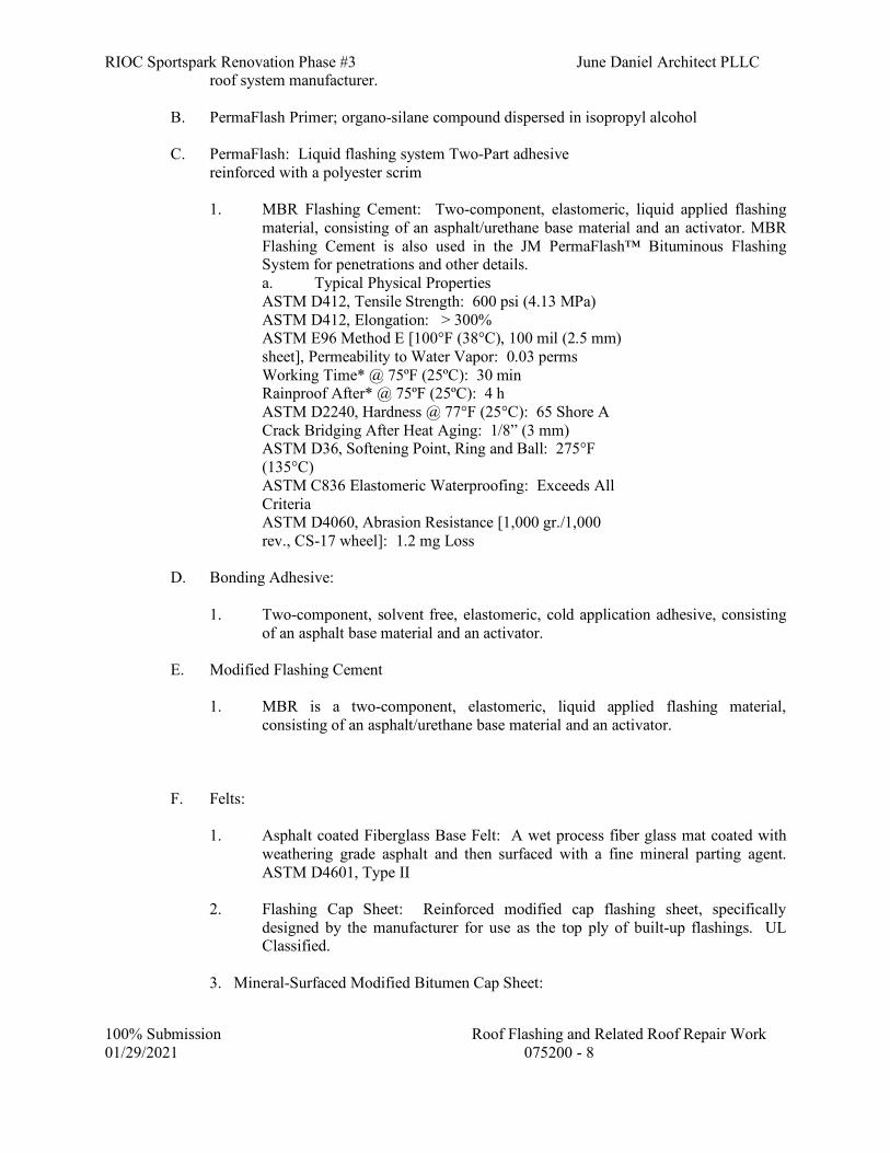
RIOC Sportspark Renovation Phase #3 June Daniel Architect PLLC
100% Submission Roof Flashing and Related Roof Repair Work 01/29/2021 075200 - 8
roof system manufacturer.
B. PermaFlash Primer; organo-silane compound dispersed in isopropyl alcohol C. PermaFlash: Liquid flashing system Two-Part adhesive
reinforced with a polyester scrim
1. MBR Flashing Cement: Two-component, elastomeric, liquid applied flashing material, consisting of an asphalt/urethane base material and an activator. MBR Flashing Cement is also used in the JM PermaFlash™ Bituminous Flashing System for penetrations and other details. a. Typical Physical Properties ASTM D412, Tensile Strength: 600 psi (4.13 MPa) ASTM D412, Elongation: > 300% ASTM E96 Method E [100°F (38°C), 100 mil (2.5 mm) sheet], Permeability to Water Vapor: 0.03 perms Working Time* @ 75ºF (25ºC): 30 min Rainproof After* @ 75ºF (25ºC): 4 h ASTM D2240, Hardness @ 77°F (25°C): 65 Shore A Crack Bridging After Heat Aging: 1/8” (3 mm) ASTM D36, Softening Point, Ring and Ball: 275°F (135°C) ASTM C836 Elastomeric Waterproofing: Exceeds All Criteria ASTM D4060, Abrasion Resistance [1,000 gr./1,000 rev., CS-17 wheel]: 1.2 mg Loss
D. Bonding Adhesive:
1. Two-component, solvent free, elastomeric, cold application adhesive, consisting of an asphalt base material and an activator.
E. Modified Flashing Cement 1. MBR is a two-component, elastomeric, liquid applied flashing material,
consisting of an asphalt/urethane base material and an activator. F. Felts: 1. Asphalt coated Fiberglass Base Felt: A wet process fiber glass mat coated with
weathering grade asphalt and then surfaced with a fine mineral parting agent. ASTM D4601, Type II
2. Flashing Cap Sheet: Reinforced modified cap flashing sheet, specifically
designed by the manufacturer for use as the top ply of built-up flashings. UL Classified.
3. Mineral-Surfaced Modified Bitumen Cap Sheet:

RIOC Sportspark Renovation Phase #3 June Daniel Architect PLLC
100% Submission Roof Flashing and Related Roof Repair Work 01/29/2021 075200 - 9
Fire resistant, coated granule surfaced modified bitumen sheet containing a core of glass fiber or polyester mat coated with flexible SBS polymer-modified asphalt. Conforming to or exceeding the requirements of ASTM D6163, or D6164, Type I Grade G. UL Classified. Initial Solar Reflectance 0.75 minimum, in accordance with Cool Roof Rating Council. Solar Reflectance Index 79 minimum, in accordance with ASTM E1980.
4. Modified Bitumen Base Sheet:
A modified bitumen sheet incorporating the features of a medium weight fiber glass mat with a blend of SBS (Styrene-Butadiene-Styrene) rubber and high quality asphalt. Conforming to or exceeding the requirements of criteria for ASTM D6163, Type I, Grade S. Thickness of 90 Mils. UL Classified.
2.04 INSULATION A. Provide type and thickness of insulation to match existing. If insulation is of a type not
specified below, utilize polyisocyanurate. Polyisocyanurate insulation shall have a 15-year time weighted average Long Term Thermal Resistance (LTTR) value of at least 5.88 for each inch of insulation thickness, as determined in accordance with ASTM C1289 or CAN/ULC-S770 (Standard Test Method for Determination of Long Term Thermal Resistance of Closed Cell Thermal Insulating Foams). Perlite and fiberboard shall have an R-value of at least 1.3 for 1/2” thickness.
1. Types
a. Polyisocyanurate - ASTM C1289, Type II, Class 1, Grade 2
b. Perlite - ASTM C728
c. Fiberboard - ASTM C208
2. All insulation: Factory Mutual, Class 1 or U.L. Class A.
B. Rigid Insulation
Provide insulation using one of the assemblies described below in subparagraph 1. or
subparagraph 2.
1. Three Layers of Insulation:
Three layers of insulation consisting of two layers of polyisocyanurate insulation, and a top layer of fiberboard or perlite insulation.
a. Polyisocyanurate Insulation: Closed cell polyisocyanurate foam core
skinned on both sides with factory applied facers of the generic type recommended by the membrane manufacturer. ASTM C1289, Type II, Class 1, Grade 2. UL Classified. Thickness of bottom layer shall be 2”. Thickness of second layer shall be not less than 1.5” and not more than 2”. Board size 48”x48” maximum.

RIOC Sportspark Renovation Phase #3 June Daniel Architect PLLC
100% Submission Roof Flashing and Related Roof Repair Work 01/29/2021 075200 - 10
1) For steel decks: Factory Mutual Class 1 approved for direct application on steel decks.
b. Top layer: 1/2" thick minimum. Perlite board insulation complying with
Federal Specification HH-1-529b, ASTM C728. Fiberboard complying with ASTM C208. UL Classified.
Provide additional layers of polyisocyanurate insulation where required to meet
indicated thermal insulating values, subject to approval of the membrane manufacturer and the Project Architect or Engineer. Total thickness of insulation shall be as indicated on the Drawings.
2. Two Layers of Insulation:
Two layers of insulation consisting of one layer of polyisocyanurate insulation, and a top layer of composite insulation. Board size 48”x48” maximum.
a. Base layer: Closed cell polyisocyanurate foam core skinned on both sides
with factory applied facers of the generic type recommended by the membrane manufacturer. ASTM C1289, Type II, Class 1, Grade 2. UL Classified. Thickness 2”.
b. Top layer: A layer of polyisocyanurate foam integrally bonded to a layer of perlite or wood fiberboard on one side and a nonasphaltic fiberglass mat on the other. Total thickness of top layer 1.5” minimum, 2.5” maximum.
Provide additional layers of polyisocyanurate insulation where required to meet
indicated thermal insulating values, subject to approval of the membrane manufacturer and the Project Architect or Engineer. Total thickness of insulation shall be as indicated on the Drawings.
2.05 MATERIALS – MISCELLANEOUS A. Cant, pre-formed treated fiber, 4” standard size. B. Wood Nailers: Preservative (pressure) treated construction grade lumber or construction
grade cedar, redwood or cypress. C. Fasteners 1. Expansion bolts, cadmium plated, 3/8” diameter. 2. Machine bolts, cadmium plated, 3/8” diameter. 3. Sheet metal screws, #8, pan head. a. Stainless steel. b. Cadmium plated steel. 4. Wood screws, #8, round head.

RIOC Sportspark Renovation Phase #3 June Daniel Architect PLLC
100% Submission Roof Flashing and Related Roof Repair Work 01/29/2021 075200 - 11
a. Brass or bronze. b. Cadmium plated steel 5. Roofing nails, “Stronghold” type with large head, 12 ga. a. Copper. b. Stainless steel. c. Galvanized steel. D. No. 1 gravel or crushed stone, clean and dry. E. Pre-manufactured Equipment Curbs: Prefabricated roof curbs shall be of box section
design, constructed using minimum 18 gauge galvanized steel, (14 gauge for curbs supporting HVAC units or as required) with fully mitered and welded corners, 3" cant. Roof Curbs shall be internally reinforced on any side longer than 3' 0" and shall have factory internal base plate. Roof Curbs to be insulated with 1 1/2" thick 3lb. density fiberglass insulation, and factory installed wood nailers fastened from underside with TEK screws. Height to be 8" above the finished roof or as detailed. Roof Curbs shall be level at the top with pitch built-in when deck slopes 1/4 of an inch per foot or greater, or as detailed. Prefabricated Roof Curbs shall be manufactured by Roof Products & Systems Corporation, Bensenville, IL. or equal. Contractor fabricated Roof Curbs will not be accepted
2.06 PRE-INSTALLATION CONFERENCE A. Before the roofing Work is scheduled to commence, a conference will be called by the
Owner's Representative at the site for the purpose of reviewing the Drawings and the Specifications and discussing requirements for the Work.
PART 3 - EXECUTION 3.01 PREPARATION – HOT-APPLIED SYSTEM A. Moisture Protection: Keep the roof waterproof. Limit removals of existing materials to
areas that can be either completed or temporarily sealed before the end of each workday. B. Limit the removal of existing materials to the absolute minimum that is necessary to
install the new Work. C. Spud off all aggregate from existing roof surfaces that will be bonded to new materials. D. Thoroughly clean, dry, and prime all existing roof surfaces that will be bonded to new
materials. E. Where existing insulation is removed to install nailers, do not remove the existing vapor
seal. Patch with asphalt cement and asphalt fiberglass felts if damaged. F. Heating Bitumen
1. Preparation

RIOC Sportspark Renovation Phase #3 June Daniel Architect PLLC
100% Submission Roof Flashing and Related Roof Repair Work 01/29/2021 075200 - 12
a. Use separate kettles or tankers for heating different types of asphalt.
Kettle may not be placed on roofs.
b. The heating process shall be strictly regulated by means of an automatic thermostatic control of an approved type for positive temperature control. Kettles or tankers shall be the immersion tube type, fire by Liquid LP gas, and shall have 100% safety shutoff.
c. Equip each kettle or tanker with a recording thermometer that will
graphically indicate and record on a chart the maximum and minimum temperatures to which materials have been heated. Recording thermometers shall be capable of accurately recording temperatures as high as 600˚F and as low as 0˚F. The thermometers shall be properly maintained at all times. Kettles or tankers without recording thermometers in good working condition shall not be used. At the end of each working day, turn the chart from the thermometer on each kettle or tanker over to the Owner's Representative. If any bitumen is overheated, remove it from the site in the presence of the Owner's Representative.
If any underheated or overheated bitumen has been applied on the roof, remove that portion of the roof.
d. Kettle is to placed on the ground, with the asphalt pumped to the roof.
1) Provide fire extinguishers on the roof in the vicinity of the work
as required to ensure the safety of the roof. 2) In all cases comply with requirements of the NYC Fire
Department in locating equipment.
2. Heating Asphalt Bitumen
a. Heat the bitumen in accordance with the Equiviscous Temperature information furnished by the bitumen manufacturer for that specific run of bitumen.
1) In no case shall be asphalt be heated to or above the actual COC
Flash Point (ANSI/ASTM D92); or the finished blowing temperature for more than 4 hours.
2) Maintain the temperature of the bitumen at the point of
application within the Equiviscous Temperature Range. Use insulated pipes, buckets, luggers, and other insulated roofers equipment as required by the field conditions.

RIOC Sportspark Renovation Phase #3 June Daniel Architect PLLC
100% Submission Roof Flashing and Related Roof Repair Work 01/29/2021 075200 - 13
Contractor must have at least one hand held thermometer for each crew installing hot asphalt in order to ensure compliance with EVT.
2. Application temperature: The accepted application temperature range for asphalt
is the equiviscous temperature, (EVT) 25˚F. All felt installation must occur in this range to be acceptable.
3.02 PREPARATION – COLD-APPLIED SYSTEM
A. Bituminous and Modified Bituminous Membranes - Basic Cold Process Repair Techniques
1. Moisture Protection: Keep the roof waterproof. Limit removals of existing
materials to areas that can be either completed or temporarily sealed before the end of each workday.
2. Limit the removal of existing materials to the absolute minimum that is necessary
to install the new Work.
3. Gravel Surfaced Bituminous membrane system - Spud off all aggregate from existing roof surfaces that will be bonded to new materials. Clean and dry surfaces approximately 12” to either side of damaged area. On aggregate surfaced roofs, the surfacing should be chipped away down to the felts.
4. Thoroughly clean, dry, and prime all existing roof surfaces that will be bonded to
new materials. Prepare surfaces with brush application of bituminous primer. 5. Modified Bituminous membrane system - Remove damaged material, clean
surfaces to be bonded. Wire brush elastomeric surfaces to remove oxidized layer, wipe with ether or acetone to remove surface moisture. Prepare surfaces with brush application of bituminous primer.
6. Where existing insulation is removed to install nailers, do not remove the
existing vapor seal. Patch with asphalt cement and asphalt fiberglass felts if damaged.
3.03 CURB INSTALLATIONS
A. Install prefabricated curbs and pipe portals as per manufacturer’s instructions and in a setting bed of modified flashing cement. Mechanically anchor using adhesive anchors.
3.04 INSTALLATION – HOT-APPLIED SYSTEM A. Wood Nailers: Set each nailer into a full bed of asphalt plastic cement and secure with
bolts (at least two each side) to the deck. Fill voids (if any) between the nailer and the existing insulation with roof insulation, set in plastic asphalt cement. Set fiber cants in plastic asphalt cement.
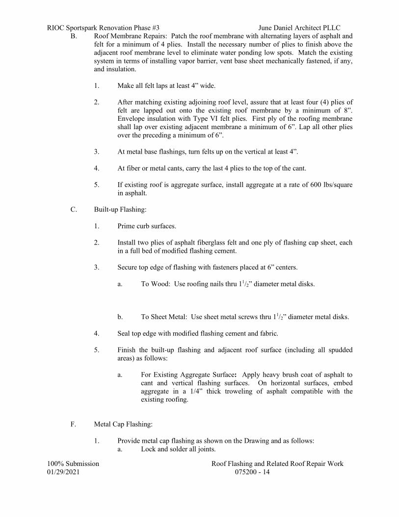
RIOC Sportspark Renovation Phase #3 June Daniel Architect PLLC
100% Submission Roof Flashing and Related Roof Repair Work 01/29/2021 075200 - 14
B. Roof Membrane Repairs: Patch the roof membrane with alternating layers of asphalt and felt for a minimum of 4 plies. Install the necessary number of plies to finish above the adjacent roof membrane level to eliminate water ponding low spots. Match the existing system in terms of installing vapor barrier, vent base sheet mechanically fastened, if any, and insulation.
1. Make all felt laps at least 4” wide. 2. After matching existing adjoining roof level, assure that at least four (4) plies of
felt are lapped out onto the existing roof membrane by a minimum of 8”. Envelope insulation with Type VI felt plies. First ply of the roofing membrane shall lap over existing adjacent membrane a minimum of 6”. Lap all other plies over the preceding a minimum of 6”.
3. At metal base flashings, turn felts up on the vertical at least 4”. 4. At fiber or metal cants, carry the last 4 plies to the top of the cant. 5. If existing roof is aggregate surface, install aggregate at a rate of 600 lbs/square
in asphalt. C. Built-up Flashing: 1. Prime curb surfaces. 2. Install two plies of asphalt fiberglass felt and one ply of flashing cap sheet, each
in a full bed of modified flashing cement. 3. Secure top edge of flashing with fasteners placed at 6” centers. a. To Wood: Use roofing nails thru 11/2” diameter metal disks. b. To Sheet Metal: Use sheet metal screws thru 11/2” diameter metal disks. 4. Seal top edge with modified flashing cement and fabric. 5. Finish the built-up flashing and adjacent roof surface (including all spudded
areas) as follows:
a. For Existing Aggregate Surface: Apply heavy brush coat of asphalt to cant and vertical flashing surfaces. On horizontal surfaces, embed aggregate in a 1/4” thick troweling of asphalt compatible with the existing roofing.
F. Metal Cap Flashing: 1. Provide metal cap flashing as shown on the Drawing and as follows: a. Lock and solder all joints.

RIOC Sportspark Renovation Phase #3 June Daniel Architect PLLC
100% Submission Roof Flashing and Related Roof Repair Work 01/29/2021 075200 - 15
b. Provide minimum of 3” lap over base flashing. c. Turn flange over top of curb and turn edge up at least 1” behind
ventilator housing. d. Seal all penetrations (ventilator housing bolts) with silicone sealant. 3.05 INSTALLATION – COLD-APPLIED SYSTEM, GRAVEL SURFACED MEMBRANE A. Wood Nailers: Set each nailer into a full bed of MBR Flashing Adhesive and secure with
bolts (at least two each side) to the deck. Fill voids (if any) between the nailer and the existing insulation with roof insulation, set in plastic asphalt cement. Set fiber cants in MBR Flashing Adhesive.
B. Roof Membrane Repairs – Patch the roof membrane with alternating layers of MBR
Bonding Adhesive and layers of fiberglass reinforced base sheet for a minimum of 3 plies. Install the necessary number of plies to finish above the adjacent roof membrane level to eliminate water ponding low spots. Match the existing system in terms of installing vapor barrier, vent base sheet mechanically fastened, if any, and insulation.
1. Membrane Installation Sequencing (from substrate to uppermost ply 2. Base sheet shall be cut into 18 foot (5.5 m) lengths and be allowed to relax before
being installed. 3. Using PermaPly 28, start with a 12” (305 mm) width. The following base sheet
courses are to be applied full width, overlapping the preceding felt 2” (51 mm) on the side laps and 4” (102 mm) on the end laps. Install felt so that it is firmly and uniformly set, without voids, into JM MBR Bonding Adhesive applied before the felt at a rate of 3 gallons per square (1.2 l/m2).
4. Using PermaPly 28, apply a piece 18” (457 mm) wide, then over that, a full
width piece. The following felts are to be applied full width, overlapping the preceding felts by 19” (483 mm) so that at least 2 plies of felt cover the base at all locations.
5. Install each felt so that it is firmly and uniformly set, without voids, into the JM
MBR Bonding Adhesive applied before the felt at a nominal rate of 11/2 to 2 gallons per square (0.6-0.8 l/m2) over the entire surface. Roll installed felts with a weighted roller before the end of each work day.
6. Surfacing:
1. After the interply adhesive has cured, apply JM MBR Bonding Adhesive at the rate of 6 gallons per square (2.4 l/m2). Into the MBR Bonding Adhesive, embed an acceptable gravel at a rate of 400 lb per square (19.5kg/m2) or an acceptable slag at a rate of 300 lb (14.6 kg/m2).
2. Aggregate must be installed so that there is complete coverage across the
entire surface and at least 50% of the aggregate is solidly adhered in the MBR Bonding Adhesive. Gravel aggregate should meet the requirements of ASTM D1863.

RIOC Sportspark Renovation Phase #3 June Daniel Architect PLLC
100% Submission Roof Flashing and Related Roof Repair Work 01/29/2021 075200 - 16
3.06 INSTALLATION – COLD-APPLIED SYSTEM, MODIFIED BITUMEN MEMBRANE A. Wood Nailers: Set each nailer into a full bed of MBR Flashing Adhesive and secure with
bolts (at least two each side) to the deck. Fill voids (if any) between the nailer and the existing insulation with roof insulation, set in plastic asphalt cement. Set fiber cants in MBR Flashing Adhesive.
B. Roof Membrane Repairs – Patch the roof membrane with alternating layers of MBR
Bonding Adhesive and layers of fiberglass reinforced base sheet for a minimum of 3 plies. Install the necessary number of plies to finish above the adjacent roof membrane level to eliminate water ponding low spots. Match the existing system in terms of installing vapor barrier, vent base sheet mechanically fastened, if any, and insulation.
C. Install modified bituminous roofing membrane sheet and cap sheet according to roofing
manufacturer's written instructions, starting at low point of roofing system. Extend roofing membrane sheets over and terminate beyond cants as follows:
1. Adhere to substrate in a approved cold applied adhesive. 2. Unroll roofing membrane sheets and allow them to relax for minimum time
period required by manufacturer.
D. Laps: Accurately align roofing membrane sheets, without stretching, and maintain uniform side and end laps. Stagger end laps. Completely bond and seal laps, leaving no voids.
1. Repair tears and voids in laps and lapped seams not completely sealed. 2. Apply roofing granules to cover exuded bead at laps while bead is hot.
E. Install roofing membrane sheets so side and end laps shed water. F. Proceed with installation only after unsatisfactory conditions have been corrected.
3.07 FLASHINGS A. Fluid-Applied Flashing System – Based on Perma-flash
1. PermaFlash primer Application – Shake bottle vigorously for 3-5 seconds prior to opening. All non-porous surfaces to receive MBR Flashing Cement should be primed no more than 1 hour prior to application. PermaFlash Primer can be wiped on with a cloth rag. Surfaces only need to be wiped once. Replace soiled rags with clean rags as necessary. Wiping on the PermaFlash Primer also helps to clean the surface. PermaFlash Primer may also be applied with spray bottles or Hudson type sprayers. Apply only a light mist when spraying. Do not over apply, creating puddles or runs. The PermaFlash Primer will flash off (dry) almost immediately. PermaFlash Primer must be dry prior to applying MBR Flashing Cement.

RIOC Sportspark Renovation Phase #3 June Daniel Architect PLLC
100% Submission Roof Flashing and Related Roof Repair Work 01/29/2021 075200 - 17
2. Lay out reinforcement fabric around penetration and cut to fit. Wrap fabric around penetration and bridge all vertical to horizontal transitions.
3. Apply fluid-applied flashing directly to prepared substrate. Adhere fabric by
pressing into the fluid-applied flashing while still wet.
4. Completely cover fabric with at least 60 mil coat wet film thickness of fluid-applied flashing, and as required by the manufacturer.
5. Extend top coat of fluid-applied flashing system 2 inches beyond edges of
reinforcement fabric. B. Built-up Flashing 1. Prime curb surfaces. 2. Install two plies of asphalt fiberglass felt and one ply of flashing cap sheet, each
in a full bed of modified flashing cement or hot asphalt. 3. Secure top edge of flashing with fasteners placed at 6” centers. a. To Wood: Use roofing nails thru 11/2” diameter metal disks. b. To Sheet Metal: Use sheet metal screws thru 11/2” diameter metal disks. 4. Seal top edge with modified flashing cement and fabric. Seal all seams with
modified flashing cement. 5. Finish the built-up flashing and adjacent roof surface (including all spudded
areas) as follows:
a. For Existing Aggregate Surface: Apply heavy brush coat of asphalt to cant and vertical flashing surfaces. On horizontal surfaces, embed aggregate in a 1/4” thick troweling of asphalt compatible with the existing roofing.
3.8 FLOOD TESTING
A. After completion of roofing work specified above, a flood test shall be performed. The flood test shall include the area of new work and extend at least an additional 4 feet past the transition to the existing membrane. The area shall be flooded with a minimum of 1" of water above the high points by providing temporary barriers. Water shall remain for a minimum of 24 hours. For each flood test performed, the Contractor shall notify the Owner’s field representative when the minimum 1” of water above high point has been reached to mark the start of test period for verification and notification to the Owner’s Construction Inspection Division to allow for inspection. If leaks occur, Contractor shall do all necessary work to correct them and flood testing shall be repeated until no leaks occur.

RIOC Sportspark Renovation Phase #3 June Daniel Architect PLLC
100% Submission Roof Flashing and Related Roof Repair Work 01/29/2021 075200 - 18
3.9 CLEANING A. Clean debris from roofs, gutters, downspouts, and drainage systems. Test drainage
system for proper operation.
END OF SECTION 07520

RIOC Sportspark Renovation Phase #3 June Daniel Architect PLLC
100% Submission Flashing and Sheet Metal 01/29/2021 076000 - 1
SECTION 076000 - FLASHING AND SHEET METAL
PART 1 - GENERAL 1.01 DESCRIPTION OF WORK
A. Provide all flashing, trim and sheet metal Work as indicated on the Drawings, as required for the completed Work, and as specified herein. The Work shall include, but shall not be limited to, the following:
1. Roof Flashings (various types)
2. Wall Flashings (various types)
3. Shop-Formed Gravel Stops
4. Gutters and Downspouts
5. Flashing at roof mounted equipment and roof penetrations. 1.02 REFERENCES
A. References and industry standards listed in this Section are applicable to the Work. Unless more restrictive criteria or differing requirements are explicitly stated in the Specifications, or mandated by governing codes or regulations, the recommendations, suggestions, and requirements described in the referenced standards shall be deemed mandatory and applicable to the Work.
B. Sheet Metal and Air Conditioning Contractors National Association (SMACNA).
C. Copper Development Association (CDA).
D. American Society for Testing and Materials (ASTM).
1.03 SUBMITTALS
A. Shop Drawings
1. Show the manner of forming, jointing, and securing the metal flashings, trim, and other specified sheet metal items. Include the method of forming waterproof connections to adjoining construction.
B. Product Data
1. Catalog sheets, specifications, installation instructions for each item specified except
for shop or job formed items, solder and flux.
2. Manufacturer's recommendations for installation and spacing of snow guards.
C. Samples

RIOC Sportspark Renovation Phase #3 June Daniel Architect PLLC
100% Submission Flashing and Sheet Metal 01/29/2021 076000 - 2
1. Materials for Flashings: One 6" sq piece, for each type material specified.
2. Anchors: Two, each type required.
3. Cap Flashings: Full section, 6" long.
4. Gravel Stop: Full section 6" long.
5. Gutters: Full section, 12" long.
6. Downspout: Full section, 12" long..
8. Termination bar, 12” section. Termination bar fasteners, stainless steel, 3 of each
type. Termination bar sealant, 1 container.
D. Guarantee
E. Certificates of qualifications as specified under Article titled “Quality Assurance”.
F. Product Certificates Certify that materials of this Section, such as copper/fabric flashing, sealants, termination
bar, and fasteners, are compatible with all components of the air barrier system and other Project materials that contact them.
1.04 QUALITY ASSURANCE
A. Except as otherwise shown or specified, comply with applicable recommendations, details, and standards of CDA, and SMACNA.
B. All metal Work shall be ink-stamped at intervals, identifying
Manufacturer, type metal, and gage or thickness.
C. Manufacturer's Recommendations
For factory fabricated items, follow the manufacturer's recommendations and installation instructions unless specifically shown or specified otherwise.
D. Materials containing asbestos are prohibited.
E. Project Foreman Qualifications
1. Successful completion of a formal instructional and training program for the
installation of the specified roofing/flashing systems, as evidenced by:
a. A certificate of journeyman roofer as issued under a union apprenticeship-journeyman training program duly registered with the New York State Department of Labor (or other State Labor Department); or

RIOC Sportspark Renovation Phase #3 June Daniel Architect PLLC
100% Submission Flashing and Sheet Metal 01/29/2021 076000 - 3
b. A certificate or diploma issued by a vocational training school or national roofing manufacturer attesting to successful completion of an equivalent formal training program. (Submit copy of certificate for above).
1.05 DELIVERY, STORAGE, AND HANDLING
A. Deliver, store, and handle products of this Section in such manner to protect them from damage.
1.06 PROJECT CONDITIONS
A. Do not execute the Work of this Section unless the Owner's Representative is present, unless otherwise directed.
B. Make the roof and all uncompleted flashings watertight at the end of each work day.
1.07 GUARANTEE
A. The Contractor shall provide a two (2) year written guarantee, covering the flashing and sheet metal materials and workmanship. Should any defects occur during the stated period, they shall be corrected immediately, and all damage caused by such defects shall be corrected; all corrective Work shall be at the Contractor's expense.
PART 2 - PRODUCTS 2.01 MATERIALS FOR FLASHING FABRICATION
A. Lead Coated copper Sheet
Cold rolled copper, ASTM B370. Lead coating; ASTM B101, Type 1 weighing 0.06 to 0.07 lbs per sq ft applied to each side.
2.02 MANUFACTURED MATERIALS
A. Copper/fabric flashing: consisting of a full sheet of copper, weight of copper core not less than 5 ounces per square foot, permanently bonded with rubber based adhesive to and between 2 layers of fiberglass or polymer fabric. Each layer of fabric shall be 0.3 oz. per sq. ft. minimum weight, with minimum 10x20 threads per inch. Flashing shall be compatible with air barrier system, sealants, adhesives, and other adjacent materials.
1. Manufacturers/Products
a. York Manufacturing, Inc., Sanford, Maine: Multi-Flash 500 Copper Fabric
Flashing. b. Advanced Building Products Inc., Springvale Maine: Copper Sealtite
2000. c. Hohmann & Barnard, Inc., Hauppauge, NY: Copper NA.

RIOC Sportspark Renovation Phase #3 June Daniel Architect PLLC
100% Submission Flashing and Sheet Metal 01/29/2021 076000 - 4
2.03 FASTENERS
A. Nails
"Stronghold" type large flat head roofing nail.
1. For Copper: Hardened copper.
2. For Stainless Steel: Stainless steel.
B. Screws, Bolts, and other Fastening Accessories
1. For Copper: Copper or brass.
2. For Stainless Steel: Stainless steel type 316.
C. Anchors
Provide one of the following types:
1. Hammer driven anchors, consisting of a stainless steel drive pin and a corrosion resistant metal expansion shield inserted thru a stainless steel disc with an EPDM sealing washer.
2. Self-tapping, corrosion resistant, concrete and masonry screw inserted thru a
stainless steel disc with an EPDM sealing washer.
D. Fasteners for Through-Wall Flashing Termination Bar 1. Tapcon Concrete Screw: stainless steel. 2.04 MISCELLANEOUS MATERIALS
A. Solder
Composition of block tin/pig lead of proportion recommended by the metal manufacturer, stamped either 50/50 or 60/40 "Warranted".
B. Flux
Paste or acid type as recommended by the metal manufacturer.
C. Type 3 Sealant (For concealed sealant joints of thru-wall cap receivers and other areas which require concealed sealant). One part butyl rubber sealant; Pecora BC-158, PTI 707, or Woodmont chem-Calk 300.
D. Termination Bar (For thru-wall copper/fabric flashing) Plastic. Provide material compatible with the air barrier system. York Manufacturing Co.,
Sanford, Maine.

RIOC Sportspark Renovation Phase #3 June Daniel Architect PLLC
100% Submission Flashing and Sheet Metal 01/29/2021 076000 - 5
E. Flashing Sealants and Adhesives
Provide products recommended in writing by the flashing manufacturer, and compatible with all adjacent materials, including components of the air barrier system. Materials containing asbestos are prohibited. Asphalt mastics and other asphaltic materials shall not be used.
1. Where low modulus silicone sealant is indicated provide ASTM C 920, single-component, neutral-curing silicone; Class 100/50, Grade NS, Use NT, Use O.
2.05 FABRICATION
A. General: Where practicable, form and fabricate sheet metal Work in the factory or shop. Produce bends and profiles accurately to the indicated shapes. Where not indicated or specified, follow the applicable requirements of the reference standards listed in PART 1. All corners to be factory prefabricated. Hem exposed sheet metal to eliminate all sharp edges and corners.
B. Cap Flashing (one-piece): Fabricated to be spring-tight against wall/base flashing. All
corners shall be factory prefabricated: mitered and lapped approximately 1” at corner, and fully soldered or welded. At expansion joints, provide v-notch splice joint with 6” lap each side.
1. Copper: 16 oz.
2. Lead Coated copper: 16 oz.
3. Stainless Steel: 26 ga (0.018").
C. Cap Flashing (two-piece) with In-Wall, Thru-Wall, or Coping Cap Receiver; All corners of
coping flashing and of cap receivers shall be factory prefabricated: mitered and lapped approximately 1” at corner, and fully soldered or welded. At expansion joints, provide v-notch splice joint with 6” lap matching three-way fabrication each side of joint. Cap flashing fabricated to be spring tight against wall/base flashing.
1. Cap Flashing: three-way mortar bond type receiver with snap fit cap flashing.
Acceptable manufacturers / products: a. Keystone Flashing Co., 5119 N. Second Street, Philadelphia, PA. "Keystone
Two-Piece cap Flashing". b. Cheney Flashing Co., 623 Prospect St., Trenton, NJ. "Cheney Prefabricated
Snap Lock Cap Flashing".
c. LITSCO, Long Island Tinsmith Supply Corp., 76-11 88th St., Glendale, NY. Two-piece snap fit cap flashing; with 3-way mortar bond receiver.
d. B & B Sheet Metal, 25-40 50th Ave. Long Island City, NY. Two-piece
snap fit cap flashing; with 3-way mortar bond receiver.

RIOC Sportspark Renovation Phase #3 June Daniel Architect PLLC
100% Submission Flashing and Sheet Metal 01/29/2021 076000 - 6
e. WG Sheet Metal Corporation. 341 Amber Street Brooklyn, NY. Cap Flashing with 3-way mortar bond receiver.
E. Base Flashing
2. Lead Coated copper: 20 oz.
F. Extruded Aluminum Gravel Stop
Complete system including gravel stop, extruded aluminum joint cover plates, concealed 0.025" aluminum joint flashing, fasteners and all other accessory components. Type F gravel stop as manufactured by Architectural Products Company, Covington, KY., or equivalent by W.P. Hickman Co., Asheville, NC.
1. Face Height: Closest manufacturer's standard dimension to face height shown on
Drawings.
2. Finish: Anodized; Color: As selected by the Project Architect.
G. Thru-Wall Flashing
1. Manufactured copper/fiberglass fabric flashing.
H. Sealant Edge Flashing 1. Stainless Steel: 26 gauge, hemmed edge.
I. Gutters and Downspouts
1. Materials: Plain copper or lead coated copper.
2. Components
a. Hung Gutter: 20 oz.
b. Downspouts: 16 oz.
c. Conductor Heads: 16 oz.
d. Outlet Tube, offsets and elbows: 16 oz.
e. Continuous cleats: 20 oz.
f. Gutter Hanger Brackets: 1" x 3/16" brass or copper bar.
g. Gutter Braces: 1" x1/8" brass or copper bar.
h. Gutter Stiffener: 3/4" x 1/8" brass or copper bar.
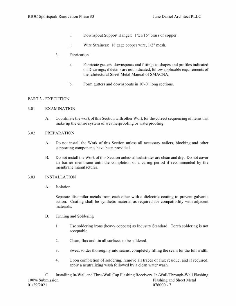
RIOC Sportspark Renovation Phase #3 June Daniel Architect PLLC
100% Submission Flashing and Sheet Metal 01/29/2021 076000 - 7
i. Downspout Support Hanger: 1"x1/16" brass or copper.
j. Wire Strainers: 18 gage copper wire, 1/2" mesh.
3. Fabrication
a. Fabricate gutters, downspouts and fittings to shapes and profiles indicated
on Drawings; if details are not indicated, follow applicable requirements of the rchitectural Sheet Metal Manual of SMACNA.
b. Form gutters and downspouts in 10'-0" long sections.
PART 3 - EXECUTION 3.01 EXAMINATION
A. Coordinate the work of this Section with other Work for the correct sequencing of items that make up the entire system of weatherproofing or waterproofing.
3.02 PREPARATION
A. Do not install the Work of this Section unless all necessary nailers, blocking and other supporting components have been provided.
B. Do not install the Work of this Section unless all substrates are clean and dry. Do not cover
air barrier membrane until the completion of a curing period if recommended by the membrane manufacturer.
3.03 INSTALLATION
A. Isolation
Separate dissimilar metals from each other with a dielectric coating to prevent galvanic action. Coating shall be synthetic material as required for compatibility with adjacent materials.
B. Tinning and Soldering
1. Use soldering irons (heavy coppers) as Industry Standard. Torch soldering is not
acceptable.
2. Clean, flux and tin all surfaces to be soldered.
3. Sweat solder thoroughly into seams, completely filling the seam for the full width.
4. Upon completion of soldering, remove all traces of flux residue, and if required, apply a neutralizing wash followed by a clean water wash.
C. Installing In-Wall and Thru-Wall Cap Flashing Receivers, In-Wall/Through-Wall Flashing

RIOC Sportspark Renovation Phase #3 June Daniel Architect PLLC
100% Submission Flashing and Sheet Metal 01/29/2021 076000 - 8
1. Set the flashing so there is mortar above and below the built-in portion. Bonding
ribs shall be completely filled with mortar.
2. Do not mallet, bend or deform the exposed portion.
3. Lap all end joints so they interlock at the first raised rib. Apply Type 3 sealant between the mating surfaces of the built-in portion of the flashing before interlocking end joints.
4. All corners shall be factory prefabricated: mitered and lapped approximately 1” at
corner, and fully soldered or welded by the manufacturer.
5. Provide splice plate at all expansion joints, 12” wide, with 6” lap each side and v-notch in center of joint.
6. Flashings that end at vertical surfaces, into windows, cavities shall be turned up
2” to form a pan.
E. Installing Cap Flashing
1. General: Form and install the cap to provide a spring tight fit against the base flashing. Lap all end joints a minimum of 6” and base flashing a minimum of 4". Extend the cap continuously around corners or provide lock seams. Install waterstop flashing at expansion joints.
2. Cap Flashing for Installation in Reglets:
a. Extend the cap flashing into the reglet, applying pressure to securely lock it
into position along its entire length. b. Pack the reglet with lead wool to within 1/4” of the reglet opening, then fill
with sealant and tool to a slightly concave surface.
3. Surface Mounted Cap Flashing:
a. Form the top portion of the cap flashing which comes in contact with the wall surface with a 1" wide bearing surface. Form a 45 degree x 1/4" wide stiffener and calking flange along the top edge.
b. Apply Type 2 sealant on the backside of the bearing surface.
c. Secure the cap flashing to the wall with fasteners spaced 12" oc thru the
bearing surface.
d. Apply Type 2 sealant along the calking flange.
5. Provide a cap flashing at roof terminations at roof curbs such as at mechanical equipment.

RIOC Sportspark Renovation Phase #3 June Daniel Architect PLLC
100% Submission Flashing and Sheet Metal 01/29/2021 076000 - 9
6. Cap flashing For Installation in Receivers: Insert the cap flashing into the receiver locking slot. Apply upward pressure along the entire length of the cap flashing so that it is securely locked into position. Nail 1” wide strap of same material as flashing at 32” o.c. prior to inserting cap in receiver. After cap installation, bend strap over edge of flashing by 1/2” to prevent flashing from coming out of receiver.
7. Pre-tin and solder with soldering irons (heavy coppers) all inside and outside
corners. Install a separate reinforced mitered corner lapping the flashing 4” each side soldered at the receiver and sown the sides.
8. Where applicable, release existing soldered lap with soldering iron, install base
flashing, dress down and re-solder existing lap.
G. Installing Base Flashings
1. Form the base flashing with locked and soldered joints into lengths not more than 24'-0" oc.
2. Provide expansion joints a maximum of 24'-0" oc on straight runs and a maximum
of 4' from corners. Form expansion joints with a 3" loose locked seam filled with Type 3 Sealant.
a. Expansion Joint: slit the cross folded portion of the flashing where it is bent
at a right angle. Solder a patch over the slit to avoid binding at the cross fold.
3. Extend the vertical portion of the base flashing a minimum of 3" up behind the cap
flashing.
a. Where shown on the Drawings, lock the base flashing to the cap flashing with a minimum 3/4" loose lock joint.
4. Extend the horizontal portion of the base flashing a minimum of 4" and terminate in
a 1/2" folded edge. Secure with nails spaced 3" oc staggered.
K. Installing Extruded Aluminum Gravel Stop
1. Install 12" wide, 0.025" concealed aluminum flashing beneath the gravel stop at all joints.
2. For single ply Membranes: Apply the membrane manufacturer's recommended
sealant between the contact surfaces of the horizontal portion of the splice plate and the gravel stop.
3. Secure the gravel stop at the mid point, and at ends of each 10'-0" section. Allow a
1/2" space between each section for expansion.
4. Provide a 6" long, exposed matching aluminum cover at all joints, fabricated to conform to the shape of the gravel stop.

RIOC Sportspark Renovation Phase #3 June Daniel Architect PLLC
100% Submission Flashing and Sheet Metal 01/29/2021 076000 - 10
Q. Installing manufactured copper/fiberglass fabric flashing.
1. Installation
a. All surfaces to receive the copper/fiberglass flashing shall be reasonably smooth, free from irregularities.
b. On horizontal masonry surfaces, lay flashing in a coat of manufacturer
recommended sealant, and with a fresh bed of mortar above the flashing. Spot vertical surfaces with sealant or other recommended material to hold flashing in place until masonry is set, and secure as detailed. Trim flashing to terminate flush with the exposed face of masonry wall, except at masonry indicated to have deeply raked joints, and as otherwise indicated.
c. For installation in conjunction with “sealant edge” indicated below, lay
flashing in a coat of manufacturer recommended sealant on top of sealant edge, with the fabric flashing cut back from the finished face.
d. Install the flashing in continuous lengths with the minimum number of
joints. Door and window flashing shall be installed in one continuous length from side to side. All seams are to have silicone sealant for entire length.
e. At corners, beams, columns, and at other junctures, fit flashing to the proper
contour. f. Fold flashing at ends to form dams at all edges.
4. Heads: Start flashing covering the toe of lintel angle or as shown on the Drawings; go over the lintel on a full coat of low modulus silicone sealant. Go up inside the wall cavity as indicated on the Drawings. Then go thru the wall turning up at the inside not less than 2", or where indicated on the Drawings provide a continuous termination bar as specified for Spandrel flashing. Extend flashing at least 6" on each side of the opening. Turn flashing at the ends, forming a 2" deep pan running entirely thru the wall. All corners shall be folded, not cut.
5. Thruwall: Start flashing cut flush with the outside face of wall. Lay flashing on
masonry in a fresh bed of mortar above and below. Extend flashing up thru the wall turning up at the inside not less than 2", or provide continuous termination bar as indicated on the Drawings to seal flashing to backup masonry or concrete after air barrier membrane is applied. Fasten bar to substrate 8” on center, with stainless steel fasteners anchored into pre-drilled pilot holes. Provide a continuous bead of low modulus silicone sealant along top of termination bar to completely seal the bar and flashing to the substrate. Confirm that all materials are compatible with the air barrier system. Where flashings end at vertical surfaces, into windows, cavities, etc., turn flashing up 2” high, fully soldered, to form a pan.
6. Joints: Lap joints at least 6”, coating the contacting surfaces with sealant
recommended by flashing manufacturer.

RIOC Sportspark Renovation Phase #3 June Daniel Architect PLLC
100% Submission Flashing and Sheet Metal 01/29/2021 076000 - 11
R. Sealant Edge Provide stainless steel sealant edge flashing on relieving angles as indicated on the Drawings
and wherever else indicated. Form flashing as required to suit lipped brick or other configuration. Adhere to relieving angle with a full coat of low modulus silicone sealant. Seal joints with sealant. Provide factory prefabricated corners and lap pieces a minimum of 4”, with a full coat of low modulus silicone. Edge shall be hemmed.
T. Gutters and Downspouts
1. Connection to Existing Construction where applicable: Tie the items of Work in
with the existing work to obtain watertight installation. Match the existing installation as much as practicable, unless otherwise specified. Repair and dress adjacent existing components as required to make secure and neat connections with new items.
2. Installation of Hung Gutters:
a. Install gutter hanger brackets 3'-0" oc. Install the brackets so there will be a
slight pitch in the gutter towards the downspouts.
b. Join the gutter sections with 1" wide lapped, riveted, and soldered seams. Use 3/16" diameter rivets spaced 2" o.c.
c. Install expansion joints where indicated on the Drawings. If not indicated,
place the expansion joints at mid points between the downspouts at maximum intervals of 48 feet.
1) Form the expansion joints with end baffles conforming to the shape
of the gutter. Rivet and solder the baffles to the gutter section.
2) Install a cover plate over the baffle.
d. Install gutter end pieces, mitered corners and outlet tubes. Solder joints and connections.
e. Install a continuous stiffener bar along the top front edge of the gutter. Fold
the gutter around the stiffener bar so it is securely locked in place.
f. Install gutter braces 3'-0" oc, staggered from the gutter hanger brackets. Secure the braces to the stiffener bar and to the back vertical portion of the gutter with brass or copper bolts.
g. Secure the top back edge of the gutter to the gravel stop, eave flashing, or
continuous cleat as indicated on the Drawings. 3. Installation of Downspouts:
a. Join the downspout sections with end joints that telescope at least 11/2"
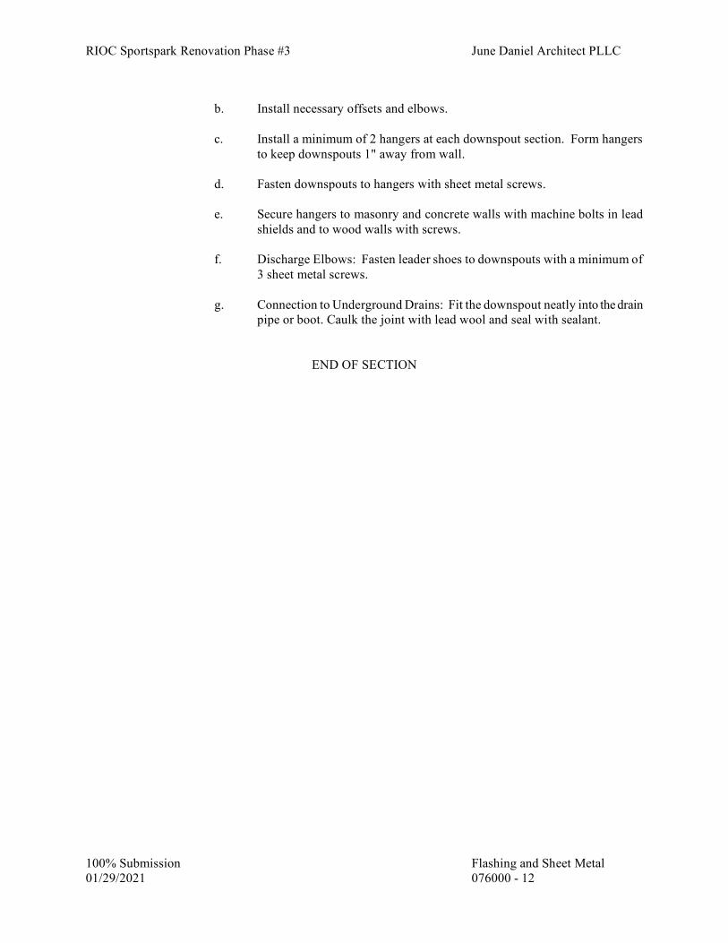
RIOC Sportspark Renovation Phase #3 June Daniel Architect PLLC
100% Submission Flashing and Sheet Metal 01/29/2021 076000 - 12
b. Install necessary offsets and elbows.
c. Install a minimum of 2 hangers at each downspout section. Form hangers
to keep downspouts 1" away from wall.
d. Fasten downspouts to hangers with sheet metal screws.
e. Secure hangers to masonry and concrete walls with machine bolts in lead shields and to wood walls with screws.
f. Discharge Elbows: Fasten leader shoes to downspouts with a minimum of
3 sheet metal screws.
g. Connection to Underground Drains: Fit the downspout neatly into the drain pipe or boot. Caulk the joint with lead wool and seal with sealant.
END OF SECTION

RIOC Sportspark Renovation Phase #3 June Daniel Architect PLLC
100% Submission Joint Sealer 01/29/2021 079000-1
JOINT SEALERS- SECTION 079000
PART 1 - GENERAL 1.01 DESCRIPTION OF WORK
A. Provide all joint sealer Work as indicated on the Drawings, as required for the completed Work, and as specified herein. This Section includes joint sealants for the following applications: 1. Exterior joints in the following vertical surfaces and horizontal nontraffic surfaces:
a. Control and expansion joints in unit masonry. . Joints between different materials listed above. k. Other joints as indicated.
2, Interior joints in the following vertical surfaces and horizontal nontraffic surfaces:
a. Control and expansion joints on exposed interior surfaces of exterior walls. b. Perimeter joints of exterior openings where indicated. c. Tile control and expansion joints. d. Vertical joints on exposed surfaces of interior unit masonry concrete walls
and partitions. e. Perimeter joints between interior wall surfaces and frames of interior doors,
windows and elevator entrances. h. Joints between plumbing fixtures and adjoining walls, floors, and counters.
i. Other joints as indicated.
1.02 REFERENCES
A. References and industry standards listed in this Section are applicable to the Work. Unless
more restrictive criteria or differing requirements are explicitly stated in the Specifications, or mandated by governing codes or regulations, the recommendations, suggestions, and requirements described in the referenced standards shall be deemed mandatory and applicable to the Work
1. American Society for Testing and Materials (ASTM)
1.03 SUBMITTALS
A. Product Data
RIOC Sportspark Renovation Phase #3 June Daniel Architect PLLC
100% Submission Joint Sealer 01/29/2021 079000-2
Catalog sheets, specifications, and installation instructions for each type of joint sealant product specified except miscellaneous materials.
B. Samples for Initial Selection:
1. For general purpose use around windows and at relieving angles, Colors of Exposed Joint Sealants: Match Architect's samples.
2. For all other uses: provide Manufacturer’s color charts consisting of strips of cured
sealants showing the full range of Manufacturer’s standard colors available for each product exposed to view.
C. Samples for Verification: For each type and color of joint sealant required, provide Samples
with joint sealants in 1/2"wide joints formed between two 6” long strips of material matching the appearance of exposed surfaces adjacent to joint sealants
D. Quality Control Submittals
1. Product Certificates: For each type of joint sealant and accessory, signed by product
manufacturer. 2. Installer's Qualifications Data: Affidavit required under Quality Assurance Article.
3. Company Field Advisor Data: Name, business address, and telephone number of
Company Field Advisor.
4. Preconstruction Test Results
a. Sealant manufacturer’s test reports certifying compatibility and adhesion with all contiguous materials.
b. Sealant manufacturer’s test reports certifying that the sealant will not stain
contiguous materials. c. The results of field adhesion testing.
E. Mockups
In accordance with Article titled Quality Assurance.
. 1.04 QUALITY ASSURANCE
A. Installer's Qualifications
The persons installing the sealants and their supervisor shall be personally experienced in the installation of sealants and shall have been regularly employed by a company engaged in the installation of sealants for a minimum of two years.
1. Furnish a letter from the sealant manufacturer, stating that the Installer is authorized
to install the manufacturer's sealant materials.
RIOC Sportspark Renovation Phase #3 June Daniel Architect PLLC
100% Submission Joint Sealer 01/29/2021 079000-3
B. Container Labels
Include manufacturer's name, trade name of product, kind of material, federal specification number (if applicable), expiration date (if applicable), and packaging date or batch number.
C. Preconstruction field-adhesion testing
Before installing sealants, field test their adhesion to Project joint substrates as follows:
1. Locate test joints as directed by Architect.
2. Conduct field adhesion tests for each kind of sealant and joint substrate. 3. Test using ASTM C1193 Method A: For joints with dissimilar substrates, verify
adhesion to each substrate separately 4. Do not use sealants that fail to adhere to joint substrates during testing.
D. Mockups
Install sealant in mockups of assemblies specified in other Sections that are indicated to receive joint sealants specified in this Section. Use materials and installation methods specified in this Section.
1.05 DELIVERY, STORAGE, AND HANDLING
A. Deliver, store, and handle joint sealer materials as recommended by the Manufacturer, to protect from damage.
1.06 PROJECT CONDITIONS
A. Environmental Requirements
1. Temperature: Unless otherwise approved or recommended in writing by the sealant manufacturer, do not install sealants at temperatures below 40°F or above 85°F.
2. Humidity and Moisture: Do not install the Work of this Section under conditions
that are detrimental to the application, curing, and performance of the materials.
3. Ventilation: Provide sufficient ventilation wherever sealants, primers, and other similar materials are installed in enclosed spaces. Follow manufacturer's recommendations.
4. Do not proceed with installation of joint sealants under the following conditions
a. When joint substrates are wet.
b. Where joint widths are less than those allowed by joint sealant manufacturer for applications indicated.
c. Contaminants capable of interfering with adhesion have not yet been
removed from joint substrates.

RIOC Sportspark Renovation Phase #3 June Daniel Architect PLLC
100% Submission Joint Sealer 01/29/2021 079000-4
d. Surfaces are frozen.
e. Surfaces are superheated by the sun. B. Protection
1. Protect all surfaces adjacent to sealants with non-staining removable tape or other
approved covering to prevent soiling or staining.
2. Protect all other surfaces in the Work area with tarps, plastic sheets, or other approved covering to prevent defacement from droppings.
3. Protect any painted surfaces which are not included in the Work from impact or
damage. PART 2 - PRODUCTS 2.01 MANUFACTURERS
A. Momentive Performance Materials-GE Silicones, Waterford, NY 12188
B. Dow Corning Corp., Midland, Michigan 48686
C. Pecora Corp., Harleyville, PA
D. Tremco Sealants and waterproofing, Beachwood, OH 44122
E. Bostik, Middleton, MA 01949 F. Sika Corporation, Lyndhurst, NJ 07071 G. Schul International, Pelham, NH 03076 H. Emseal Joint Systems Ltd., Westborough, MA 01581
2.02 SEALANTS
A. Type 1 Sealant (for use in vertical expansion joints where movement occurs; for general purpose use around windows, door frames, louvers, and other junctures).
1. One-part low-medium modulus silicone sealant (plus or minus 50% movement);
ASTM C920 classifications type S, grade NS, class 25, uses NT, M, G, and A: General Electric Silpruf SCS2000, Dow Corning 791, Pecora 864NST, Tremco Spectrem 2 or Sika SikaSil WS 295.
Silicones shall meet the following requirements:
- ASTM C719 - Low-Medium Modulus (+ or - 50%). Sealants shall not
exhibit any cracking or surface degradation after 5000 hours exposure in the Atlas Twin Arc Weatherometer.
- ASTM C661 - Shall not incur a durometer increase greater than 10 points.

RIOC Sportspark Renovation Phase #3 June Daniel Architect PLLC
100% Submission Joint Sealer 01/29/2021 079000-5
- Sealants shall contain zero parts of toxic isocyanurate ingredients.
Provide custom colors for use around window perimeters, to match window frame or masonry, or other colors as determined by the Architect.
D. Type 1C Sealant - For general use around windows, store front systems, door frames, metal
panel systems, metal coping, louvers, cast stone copings and other junctures where movement occurs.
One-part ultra-low modulus neutral cure silicone sealant; ASTM C920 classifications type S,
grade NS, class 25, uses NT, M, G, A and O: Pecora 890 FTS; Tremco Spectrem-1 or Dow Corning 790 or Sika SikaSil WS 290.
Provide custom colors for use around window perimeters, to match window frame or
masonry, or other colors as determined by the Architect.
E. Type 1D Sealant (use at interior wet areas only-- Bath and Shower areas)
One-part, mildew resistant silicone sealant; ASTM C920 classifications type S, grade NS, class 25, uses NT, M, G and A: Dow Corning 786-M, General Electric Sanitary SCS1700, Pecora 898-NST, Sika Sikasil -N plus or Tremco Tremsil 200 with fungicide.
F. Type 2 sealant (narrow joint seam sealer for joints & cracks 1/4" or less in width)
Silicone sealers: Pecora 1215 seam sealer or Dow Corning 1299
G. Type 3 Sealant (for concealed bedding only).
One-part butyl rubber sealant; Pecora BC-158, Bostik Chem-Calk 300, or Tremco Butyl.
I. Type 5 Sealant (use at relieving angles - between brick and stainless steel sealant edge)
One-component polyurethane sealant; ASTM C920 classifications type S, grade NS, class 25, uses NT, M, and A, Tremco – Dymonic 100, Sikaflex-15LM, Pecora Dynatrol I-XL Provide custom paint colors for use at relieving angles.
2.03 JOINT FILLERS
A. Elastomeric Tubing Sealant Backings: (for precast panel joints not compatible with Silicone Sealants): Neoprene, butyl or EPDM tubing complying with ASTM D1056, nonabsorbent to water and gas, and capable of remaining resilient at temperatures down to minus 26ºF (minus 32ºC). Provide products with low compression set and of size and shape to provide a secondary seal, to control sealant depth, and to otherwise contribute to optimum sealant performance.
ASTM D1056, Class SC (oil resistant and medium swell), 2 to 5 psi compression deflection.
B. Expanded Polyethylene Joint Filler (for existing joints)

RIOC Sportspark Renovation Phase #3 June Daniel Architect PLLC
100% Submission Joint Sealer 01/29/2021 079000-6
Flexible, compressible, closed-cell polyethylene of not less than 10 psi compression deflection (25 percent).
C. Closed-Cell Polyurethane or Closed-Cell Expanded polyethylene Joint Filler (for all cast-in-
place concrete work).
Resilient, compressible, semi-rigid; W.R. Meadow Ceramar or equal.
D. ASTM D1056, Class RE41 (for masonry joints) where shown on the Drawings.
2.04 MISCELLANEOUS MATERIALS
A. Primer: Material recommended by joint sealant manufacturer where required for adhesion of sealant to joint substrates indicated, as determined from preconstruction joint-sealant-substrate tests and field tests.
1. For primers used on site and within the weatherproofing/waterproof membrane
(interior) of the building comply with V.O.C. requirements specified in Section G01600.
B. Cleaners for Nonporous Surfaces: Chemical cleaners acceptable to manufacturers of sealants
and sealant backing materials, free of oily residues or other substances capable of staining or harming joint substrates and adjacent nonporous surfaces in any way, and formulated to promote optimum adhesion of sealants to joint substrates.
1. For cleaners used on site and within the weatherproofing/waterproof membrane
(interior) of the building comply with V.O.C. requirements specified in Section G01600.
C Masking Tape: Nonstaining, nonabsorbent material compatible with joint sealants and
surfaces adjacent to joints.
D. Provide sealant backings of material and type that are nonstaining; are compatible with joint substrates, sealants, primers, and other joint fillers; and are approved for applications indicated by sealant manufacturer based on field experience and laboratory testing.
1. Cylindrical Sealant Backings: ASTM C1330, Type C (closed-cell material with a
surface skin), Type O (open-cell material) or Type B (bicellular material with a surface skin), as approved in writing by joint-sealant manufacturer for joint application indicated, and of size and density to control sealant depth and otherwise contribute to producing optimum sealant performance:
E. Bond Breaker Tape
Polyethylene or other plastic tape as recommended by the sealant manufacturer; non-bonding to sealant; self-adhesive where applicable.
PART 3 - EXECUTION 3.01 EXAMINATION

RIOC Sportspark Renovation Phase #3 June Daniel Architect PLLC
100% Submission Joint Sealer 01/29/2021 079000-7
A. Examine all joint surfaces for conditions that may be detrimental to the performance of the completed Work. Do not proceed until satisfactory corrections have been made.
3.02 PREPARATION
A. Clean joint surfaces immediately before installation of sealant and other materials specified in this Section.
1. Remove all loose materials, dirt, dust, rust, oils and other foreign matter that will
impair the performance of materials installed under this Section.
2. Remove lacquers, protective coatings and similar materials from joint faces with manufacturer's recommended solvents.
3. Thoroughly clean surfaces on which sealant is to be applied using methods such as
grinding, acid etching or other approved and manufacturer's recommended means, if required, to clean the joint surfaces, assuring that the sealant materials will obtain positive and permanent adhesion.
4. Prime surfaces, if required, as recommended by Manufacturer before applying
sealant.
B. For Pavements, Walks, and Curbs
1. Set joint fillers at proper depth and position as required for installation of bond breakers, backer rods, and sealants. Do not leave voids or gaps between the ends of joint filler units.
a. Smooth Edged Joints: For joints between two concrete slabs or where new
concrete abuts smooth-edged materials, use either cork joint filler or closed cell polyurethane joint filler.
b. Irregular Edged Joints: For joints where new concrete abuts granite curbs
or other irregular edges, use closed cell polyurethane joint filler.
c. Priming Joint Surfaces:
1) Prime joints which are to receive Type 1A and 1B Sealants.
2) For joints of friable (crumbly, chalky) masonry surfaces and other surfaces which are to receive Type 1 Sealant, prime as recommended by Manufacturer.
3) Prime joints other than those above if so recommended by the
manufacturer's printed instructions.
4) Do not allow the primer/sealer to spill or migrate onto adjoining surfaces.
3.03 JOINT BACKING INSTALLATION
A. Install bond breaker tape in relaxed condition as it comes off the roll. Do not stretch the tape. Lap individual lengths.

RIOC Sportspark Renovation Phase #3 June Daniel Architect PLLC
100% Submission Joint Sealer 01/29/2021 079000-8
B. Install backer rod of sufficient size to fill the joint width at all points in a compressed state.
Compress backer rod at the widest part of the joint by a minimum of 25 percent. Do not cut or puncture the surface skin of the rod.
3.04 SEALANT INSTALLATION
A. Except as shown or specified otherwise, install sealants in accordance with the manufacturer's printed instructions.
B. Install sealants with ratchet hand gun or other approved mechanical gun. Where gun
application is impracticable, install sealant by knife or by pouring, as applicable.
C. Finishing
Tool all vertical, non-sag sealants so as to compress the sealant, eliminating all air voids and providing a neat smoothly finished joint. Provide slightly concave joint surface, unless otherwise indicated or recommended by the manufacturer.
1. Use tool wetting agents as recommended by the sealant manufacturer.
3.05 FIELD QUALITY CONTROL
A. Field Adhesion Testing of Sealants - Test completed elastomeric joints as follows: 1. Extent of Testing: Test completed elastomeric sealant joints as follows:
a. Perform 10 tests for the first 1000 feet of joint length for each type of elastomeric sealant and join substrate.
b. Perform one test for each 1000 feet of joint length thereafter or one test per
each floor per elevation.
2. Test Method – Test joints by hand pull method described below:
a. Make knife cuts from one side of the joint to the other, followed by two cuts approximately 2 inches long at sides of joint and meeting cross cut at one end. Place a mark 1 inch from cross-cut end of 2 inch piece.
b. Use fingers to grasp 2 inch piece of sealant between cross-cut end and 1”
mark, pull firmly at a 90 degree angle or more in direction of side cuts while holding a ruler along sides of sealant. Pull sealant out of joint to the distance recommended by the sealant manufacturer for testing adhesive capability, but not less than that equaling specified maximum movement capability in extension, hold this position for 10 seconds.
c. For joints with dissimilar substrates, check adhesion to each substrate
separately. Do this by extending cut along one side, checking adhesion to opposite side.
3 Inspect joints for complete fill, for absence of voids, and for joint configuration
complying with specified requirements. Record results in a field-adhesion-test log.

RIOC Sportspark Renovation Phase #3 June Daniel Architect PLLC
100% Submission Joint Sealer 01/29/2021 079000-9
4. Inspect tested joints and report on the following:
a. Whether sealants in joints connected to pulled-out portion failed to adhere
to joint substrates or tore cohesively. Include data on pull distance used to test each type of product and joint substrate. Compare these results to determine if adhesion passes sealant manufacturer's field-adhesion hand-pull test criteria.
b. Whether sealants filled joint cavities and are free of voids. c. Whether sealant dimensions and configurations comply with specified
requirements. 5. Record test results in a field-adhesion-test log. Include dates when sealants were
installed, names of persons who installed sealants, test dates, test locations, whether joints were primed, adhesion results and percent elongations, sealant fill, sealant configuration, and sealant dimensions.
6. Repair sealants pulled from test area by applying new sealants following same
procedures used originally to seal joints. Ensure that original sealant surfaces are clean and that new sealant contacts original sealant.
7. Evaluation of Field Test Results: Sealants not evidencing adhesive failure from
testing or noncompliance with other indicated requirements will be considered satisfactory. Remove sealants that fail to adhere to joint substrates during testing or to comply with other requirements. Retest failed applications until test results prove sealants comply with indicated requirements.
3.06 CLEANING
A. Immediately remove misapplied sealant and droppings from metal surfaces with solvents and wiping cloths. On other materials, remove misapplied sealant and droppings by methods and materials recommended in writing by the manufacturer of the sealant material.
B. After sealants are applied and before skin begins to form on sealant, remove all masking and
other protection and clean up remaining defacement caused by the Work. END OF SECTION

RIOC Sportspark Renovation Phase #3 June Daniel Architect PLLC
100% Submission 01/29/2021 081100-1
SECTION 081100- METAL DOORS AND FRAMES
PART 1 - GENERAL 1.01 DESCRIPTION OF WORK
A. Provide steel doors and frames as indicated on Drawings and specified herein.
1.02 REFERENCES
A. References and industry standards listed in this Section are applicable to the Work. Unless more restrictive criteria or differing requirements are explicitly stated in the Specifications, or mandated by governing codes or regulations, the recommendations, suggestions, and requirements described in the referenced standards shall be deemed mandatory and applicable to the Work.
1. Underwriters' Laboratories, Inc. (UL)
2. ASTM International (ASTM)
3. National Fire Protection Association (NFPA)
4. Steel Door Institute (SDI)
5. Hollow Metal Manufacturers Association (HMMA)
6. Interteck
7. National Fenestration Rating Council (NFRC) 8. International Organization for Standardization (ISO) 9. European Standards (EN)
1.03 SUBMITTALS
A. Product Data
Manufacturer's catalog sheets, specifications, and installation instructions.
B. Shop Drawings:
1. Show details of each frame type, elevation and construction for each door type, conditions at openings, location for each door type, location and installation requirements for finish hardware (including cutouts and reinforcements), details of connections, and anchorage and accessory items.
2. Include a schedule of doors and frames using the same reference numbers for
details and openings as those on the Contract Drawings.

RIOC Sportspark Renovation Phase #3 June Daniel Architect PLLC
100% Submission 01/29/2021 081100-2
C. Samples
1. Frames: Corner sample of each type, 18" x 18" with mortises and reinforcements, shop primed.
2. Doors: Corner sample of each type showing construction, 18" x 18", with
mortises and reinforcements, shop primed.
D. Quality Control Submittals
1. Include approval data and acceptance by a New York City Building Department approved testing agency for all fire-rated assemblies.
2. Provide certification glazing meets safety impact requirements of CPSC 16 CFR
1201. 3. Provide certification for oversized assemblies as described in Quality Assurance. 4. Air infiltration rate report for exterior doors: Manufacturer’s statement that the
fenestration assembly with opaque door when subjected to air infiltration test in accordance with NFRC 400, the air infiltration did not exceed 0.20 cubic feet per minute per square foot of door opening.
E. Warranties Provide manufacturer/installer warranty. 1.04 QUALITY ASSURANCE A. Provide doors and frames complying with ANSI/SDI A250.8 and as herein specified.
B. Fire Rated Assemblies
Wherever fire resistance classification is shown or scheduled for steel doors and frames, provide fire rated units that have been tested as fire door assemblies and comply with National Fire Protection Association (NFPA) Standard No. 80, are tested in accordance with NFPA 252 or UL 10B/UL 10C and UL 1784 as required by the NYC Building Code and comply with these Specifications. Identify each door and frame with metal UL, or Warnock Hersey labels indicating applicable fire class of the unit. Rivet or weld labels on the hinge edge of door and jamb rabbet of frame.
1. Oversize Assemblies: Whenever fire rated assemblies are larger than size
limitations established by NFPA, provide manufacturer's certification that they have been constructed with materials and methods equivalent to requirements for labeled construction.
2. See Door Schedule in the Drawings for Label Requirements (Class) for
respective openings.

RIOC Sportspark Renovation Phase #3 June Daniel Architect PLLC
100% Submission 01/29/2021 081100-3
C. Regulatory Requirements
1. Not withstanding the requirements for fire-rated assemblies noted above, all fire-
rated doors and frames shall be listed and labeled showing the name of the manufacturer. Provide permanent labels on doors and frames as required by the New York City Building Code. Labels shall be applied at the factory or where fabrication and assembly are performed.
1.05 DELIVERY, STORAGE, AND HANDLING
A. Store doors and frames on raised platforms in vertical position with blocking between
units to allow air circulation.
B. During delivery, storage and handling, protect doors and frames from water damage.
C. Provide delivery, storage and handling in such manner to prevent damage to products. 1.06 FIELD EXAMINATION
A. At the Site, before door installation, the Owner's Representative reserves the right to select at random one or more doors for examination by cutting a portion of such size to reveal the construction of the particular door.
1. If the examination finds that the doors examined do not comply with
requirements of the Specifications, all doors shall be removed from the Site and new doors shall be provided. Costs of examination and replacement of rejected doors shall be borne by Contractor.
2. If the examination finds that the doors do comply with the requirements of the
Specifications, the cost of the examination and the cost of the replacement of the examined doors will be borne by the Owner's Representative.
1.07 GAGE STANDARDS
A. Gages specified are based on U.S Standard Gauge for hot rolled and cold rolled steel sheets.
B. The allowable tolerances for steel sheet thicknesses shall be in accordance with HMMA
Standards. 1.08 WARRANTY A. Submit warranty signed by manufacturer and installer, agreeing to replace assemblies
which fail in materials, performance or workmanship within the specified warranty period.
1. Warranty Period: 1 year from date of Substantial Completion.

RIOC Sportspark Renovation Phase #3 June Daniel Architect PLLC
100% Submission 01/29/2021 081100-4
PART 2 - PRODUCTS 2.01 MANUFACTURERS
A. Interior Doors
1. General Fireproof Door Corp., Bronx, NY 10474
2. Acme & Dorf Door Corp., Clifton NJ 07011
3. Ceco Door Products Div., Milan, TN 38358
4. Curries Company, Mason City, IA 50401
5. Metalline Fire Door Co., Bronx, NY 10457
6. Long Island Fireproof Door, Port Washington, NY 11050
7. Michbi Doors Inc. Brentwood, NY 11717 2.02 MATERIALS
A. Hot-Rolled Steel Sheets and Strip
Commercial quality carbon steel, pickled and oiled, complying with ASTM A1011 and ASTM A568.
B. Cold-Rolled Steel Sheets
Commercial Quality carbon steel complying with ASTM A1008 and ASTM A568.
C. Galvannealed Steel Sheets
Carbon steel sheets of commercial quality complying with ASTM A653 Doors and frames shall have A60 zinc-iron coating, mill phosphatized, complying with ASTM A653
D. Anchors and Supports
Fabricate of gages indicated on and of not less than 16-gage sheet steel, unless otherwise indicated, on the drawings
1. Galvanized Units: Galvanized anchors and supports used with galvanized frames,
complying with ASTM A153, Class B.
E. Anchorage Devices, Bolts, and other Fasteners
Manufacturer's standard units unless otherwise indicated on the Drawings.

RIOC Sportspark Renovation Phase #3 June Daniel Architect PLLC
100% Submission 01/29/2021 081100-5
1. Galvanized Units: Galvanized items used with galvanized frames complying with ASTM A153, Class C or D as applicable.
2.03 FABRICATION
A. Fabricate hollow metal work accurately and assemble neatly to ensure work smooth and
free from dents, tool marks, visible waves, warp, buckles and conspicuous joints.
B. Align lines straight and true with arises and angles as sharp as practicable. Miter corners in true alignment and join similar abutting profiles accurately.
C. Assemble all joints to form imperceptible intersections when finished.
D. Form each member, such as jamb and head, from a single piece of metal, unless
otherwise shown or approved.
E. Fasten all members together to provide rigid construction in assembled work. Weld all connections except those for removable members such as glazing beads.
F. Weld, dress smooth and flush joints on exposed faces.
G. Clearances
Fabricate doors for their respective frames within the following clearances:
1. Jambs and Head: 3/32" to 1/8".
2. Meeting Edges of Pairs: 1/8" to 3/16".
3. Bottom (no threshold or carpet): 3/8", maximum.
4. Bottom (at threshold or carpet): 1/4", maximum.
2.04 DOORS
A. General
1. Provide steel doors of types and styles indicated on drawings or schedules. Comply with ANSI/SDI A250.8 requirements unless more restrictive requirements are specified herein.
2. Design and Thickness: Flush design doors, seamless vertical edges, hollow
construction, 1¾" thick unless specifically noted otherwise.
3. Sound Deadening (ASTM E90): Minimum Sound Transmission Class (STC) of
30.
4. Door Edges: Bevel lock stile edge of single acting hinged doors 1/8" in 2". Double acting doors shall have rounded edges, approximately

RIOC Sportspark Renovation Phase #3 June Daniel Architect PLLC
100% Submission 01/29/2021 081100-6
2¼" radius. Meeting stiles of pairs of single acting doors shall be "V" beveled or rounded as detailed on the Drawings or required.
5. Glazing Stops and Beads: Fixed steel stops, formed integral with door unless
otherwise approved by the Owner's Representative, on the outside of exterior doors and on the secure side of interior doors. Removable steel beads, of tubular steel of gage indicated on the Drawings or solid bar stock, on the other side of doors secured with machine screws. Form corners with butted hairline joints. Coordinate width of rabbet between fixed stop and removable bead and depth of rabbet with type of glass and glazing required.
6. Glazing: a. Non-rated doors - 1/4” thick minimum laminated glass meeting safety
impact requirements of CPSC 16 CFR 1201.
b. Fire-rated doors – Fire Protection rated glazing meeting safety impact requirements of CPSC 16 CFR 1201.
c. Fire-protection-rated glazing in excess of 100 square inches shall be
permitted in fire door assemblies when tested as components of the door assemblies and not as glass lights per Section BC 715.4.4 the 2014 NYC Building code.
Size and location of vision panels shall be as indicated on the drawings. C. Interior Doors
1. Fabricate interior doors with two outer stretcher-leveled, steel sheets of 16-gage
unless indicated otherwise on the Drawings. Construct doors with smooth, flush surfaces without visible joints or seams on exposed faces and stile edges, except around glass and louver panels. On mortise face of door, vertical joints shall be welded, filled and ground smooth.
2. Provide surface sheet reinforcement for surface sheet, edge, hardware, stops and
other provisions, of size and gage as detailed on Drawings.
3. Provide 16-gage top and bottom channels and closures as detailed on the Drawings.
4. For all toilet room, locker room, mechanical room, and other doors indicated on
the door schedule, all outer sheets of the door shall be galvannealed and welds shall be coated with zinc rich primer.
D. Louvered Panels for Doors
1. Provide steel louvers for doors where indicated on Drawings and as specified
herein. Cold rolled steel with mitered and welded corners and factory-applied baked enamel primer finish. Spanner head security fasteners, countersunk.

RIOC Sportspark Renovation Phase #3 June Daniel Architect PLLC
100% Submission 01/29/2021 081100-7
2. Fixed Blade Design - Anemostat Door Products model AFDL or approved equal, modified to have 16-gage frame and 16-gage vision-proof louver blades.
3. Fire Rated Design - Anemostat Door Products model FLDL-UL or approved
equal, 16-gage frame and blades, fusible link release mechanism. Comply with requirements of NYC Building Code. The assembly shall be acceptable by a New York City Building Department approved testing agency.
2.05 FRAMES
A. General
1. Provide steel frames for doors, transoms, sidelites, borrowed lites, and other openings where shown, of size and profile as indicated on Drawings.
2. Construction: Full-welded unit construction, with corners mitered and
continuously welded full depth and width of frame, unless otherwise indicated. Knock-down type frames will not be accepted.
a. Fixed Stops: Integral 5/8" stop unless otherwise indicated. Construct
jambs and heads from one piece of metal each; rabbeted and flanged as required for the various types of openings, and neatly mitered or interlocked and welded together. Provide channel, angle and bent plate reinforcing as indicated on approved Shop Drawings or otherwise required. Provide reinforcing in the heads of frames where shown or required.
3. Frame Material
a. Exterior Frames: 12-gage Galvannealed steel sheet unless indicated
otherwise on Drawings.
b. Interior Frames: 14-gage Galvannealed steel sheet unless indicated otherwise on Drawings.
4. Provide frames for masonry openings with adjustable Underwriter's type
masonry anchors to suit conditions of installation, using not less than three (3) at each jamb, in addition to floor anchors.
5. Provide frames with calking stops, filler pieces and trim where indicated on
Drawings or required; integrally formed as part of the frame wherever possible. Applied calking stops, filler pieces, and other members as indicated, shall be neatly attached by spot welding. All welds at galvannealed frames shall be painted with zinc-rich primer.
6. At butts, cut back jamb the thickness of one leaf of butt.
7. Drill and tap reinforcement to template.
8. Spot weld 20-gage plaster guard to frame at latch cutouts, if applicable. Paint all
welded areas with zinc-rich primer.

RIOC Sportspark Renovation Phase #3 June Daniel Architect PLLC
100% Submission 01/29/2021 081100-8
9. Provide reinforcement for hardware as indicated on Drawings and as required for
proper hardware installation. Refer to Section 08710 - Finish Hardware. 10. Provide frames for other openings as indicated on the Drawings. 11. Provide cutouts and reinforcing for security devices as required.
2.06 SHOP PAINTING
A. All doors shall be delivered to the site with a full shop coat. Doors not fully shop coated shall not be accepted.
B. Chemically wash, rinse, and dry exposed and concealed surfaces of fabricated units.
C. Apply one coat of rust-inhibiting primer (Carboline “Carbozinc 11 HS” or approved
equal) to all exposed surfaces of ungalvannealed doors and frames. Use the same paint to touch up all welded areas of galvannealed doors and frames. Apply primer per the manufacturer’s recommendations
D. Units shall pass the following tests:
1. Salt Spray Test complying with ASTM B117 for 120 continuous hours.
2. Water fog Test Complying with ASTM D1735 or ASTM D4585 for 240
continuous hours PART 3 - EXECUTION 3.01 EXAMINATION
A. Verification of Conditions
Examine substrate and conditions, under which the frames are to be installed, for defects which will adversely affect the execution and quality of the Work. Do not proceed until unsatisfactory conditions are corrected.
3.02 INSTALLATION
A. Install steel doors, frames, and accessories in accordance with the Drawing Details, approved Shop Drawings, and the manufacturer’s printed instructions, except as otherwise indicated.
B. Frame Installations
Place frames accurately in position; plumb, align, and brace securely until permanent anchors are set. After wall construction is complete, remove temporary braces and spreader bars, leaving surfaces smooth and undamaged.

RIOC Sportspark Renovation Phase #3 June Daniel Architect PLLC
100% Submission 01/29/2021 081100-9
1. At in-place concrete and in-place masonry construction, place frames and secure in place with anchorage devices. Set anchorage devices opposite each anchor location, in accordance with details on approved Shop Drawings and anchorage device manufacturer's instructions. Leave drilled holes rough, not reamed, and free from dust and debris.
a. Anchor frames as detailed on the Drawings.
2. Place fire rated frames in accordance with NFPA Standard No. 80.
3. Provide necessary field splices in frames as detailed on approved Shop Drawings,
welded and finished to match factory fabrication.
4. Extend jambs to structural floor slab and securely anchor in place. C. Door Installation
1. Install doors accurately in their respective frames within the clearance specified
in Part 2.
2. Place fire rated doors with clearances as specified in NFPA standard No. 80.
D. Drill and tap doors and frames to receive surface applied hardware.
3.03 ADJUSTING
A. Prime Coat Touch-up
Immediately after installation, sand smooth and clean rusted and damaged areas of shop prime coat and apply touch-up of original primer.
B. Final Adjustments
Check and adjust operating finish hardware items prior to final inspection. Leave work in complete and proper operating condition.
3.04 CLEANING
A. Clean doors, frames, and accessories, leaving free of dirt and other foreign material after completion of installation.
END OF SECTION

RIOC Sportspark Renovation Phase #3 June Daniel Architect PLLC
100% Submission Access Doors 01/29/2021 083100 - 1
SECTION 083100 - ACCESS DOORS
PART 1 - GENERAL
1.01 DESCRIPTION OF WORK
A. Provide all access doors and frames located in walls and in ceilings, complete with accessories, as indicated on the Drawings and as specified herein.
1.02 REFERENCES
A. References and industry standards listed in this section are applicable to the Work. Unless more restrictive criteria or differing requirements are explicitly stated in the Specifications, or mandated by governing codes or regulations, the recommendations, suggestions, and requirements described in the referenced standards shall be deemed mandatory and applicable to the Work.
1. New York City Building Code
1.03 SUBMITTALS
A. Product Data
For each type of door and frame indicated. Include catalogue cuts, construction details relative to materials, individual components and profiles, finishes, and fire ratings (if required) for access doors and frames.
B. Shop Drawings
Schedule: Provide complete door and frame schedule, including types, general locations, sizes, construction details, latching or locking provisions, and other data pertinent to installation. Indicate locations of fire rated doors on schedule.
C. Certification and listing by an Approved Agency in accordance with NYC Dept. of Buildings rules, indicating that the materials and assemblies as regulated by the NYC Building Code is acceptable for the intended use. When test methods are stipulated in the NYC Building Code, the tests utilized shall be stated in the Certification. Prior MEA and BSA approvals are acceptable for materials conforming to current Code requirements.
Fire rated access doors are regulated assemblies. D. Keys
Furnish 6 keys for all locks

RIOC Sportspark Renovation Phase #3 June Daniel Architect PLLC
100% Submission Access Doors 01/29/2021 083100 - 2
1.04 QUALITY ASSURANCE
A. Fire rated Doors
1. Fire Rated Access Doors for Walls: Complete assemblies meeting NYC Building Code requirements for 1½ hour rating for a 2-hour wall. Each assembly shall be labeled by an agency approved pursuant to rules of the NYC Dept. of Buildings. The label shall meet Building Code requirements and shall be permanently affixed at the factory.
2. Fire Rated Access Doors for Ceilings: Complete assemblies complying with NYC Building Code requirements for one-hour combustible and one-hour non-combustible floor/ceiling systems. Each assembly shall be labeled by an agency approved pursuant to rules of the NYC Dept. of Buildings. The label shall meet Building Code requirements and shall be permanently affixed at the factory.
1.05 COORDINATION
A. Verification: Determine specific locations and sizes for access doors needed to gain access to concealed equipment, and indicate on schedule specified in "Submittals" Article.
1.06 DELIVERY, STORAGE, AND HANDLING
A. Deliver, store, and handle access doors and frames as recommended by the Manufacturer, to protect from damage.
PART 2 - PRODUCTS
2.01 ACCEPTABLE MANUFACTURERS
A. Karp Associates, Inc., Maspeth, NY 11378
B. Milcor, Inc., Lima, OH 45804
C. Nystrom Building Products, Minneapolis, MN 55413
2.02 NON-FIRE RATED ACCESS DOORS
A. Frames
Minimum 16 gage steel.
1. Flange: Integral exposed flange not less than 3/4" wide around the perimeter.

RIOC Sportspark Renovation Phase #3 June Daniel Architect PLLC
100% Submission Access Doors 01/29/2021 083100 - 3
2. Plaster Applications: Expanded metal lath and exposed casting bead welded to perimeter of frame, in place of integral exposed flange.
3. Acoustical Tile Applications: Frames without exposed flange.
a. Finish: Factory-applied rust inhibitive baked enamel primer over phosphate treated steel.
b. Anchorage: Predrilled holes in frame for anchoring with fasteners.
B. Flush Type Door Panel
Minimum 14 gage steel.
1. Hinges: Concealed spring type set to open to approximately 175o; sufficient number to support the door size, or continuous type hinge.
2. Finish: Factory-applied rust inhibitive baked enamel primer over phosphate treated steel.
C. Cam Locks (for doors located in ceilings)
Flush, screwdriver operated; sufficient number to hold door panel in flush, smooth plane when closed.
D. Cam Locks (for doors located in walls)
Flush screwdriver or key operated; sufficient number to hold door panel in flush, smooth plane when closed.
1. One lock on each door panel shall be key operated, pin tumbler type. The remaining locks, if any, shall be screwdriver operated type.
2.03 FIRE RATED ACCESS DOORS FOR WALLS
A. Frames
Minimum 16 gage steel, with integral exposed flange not less than 1" wide around the perimeter.
1. Anchorage: Predrilled holes in frame for anchoring with fasteners.
B. Flush Type Door Panel

RIOC Sportspark Renovation Phase #3 June Daniel Architect PLLC
100% Submission Access Doors 01/29/2021 083100 - 4
Minimum 20 gage steel double wall construction with insulation, equipped with automatic closer and inside release mechanism.
1. Hinge: Continuous hinge set to open to approximately 175o.
2. Finish: Factory-applied baked enamel primer over phosphate treated steel.
C. Automatic Latches
Direct action Knurled knob or turn ring, or key operated; sufficient number to hold door panel in flush, smooth plane when closed.
1. One latch on each door panel shall be key operated, pin tumbler type. The remaining latches, if any, shall be knurled knob or turn ring operated type.
2.04 KEYING FOR NON-FIRE RATED ACCESS DOORS AND FIRE RATED ACCESS DOORS FOR WALLS
A. Key all locks and latches alike. Furnish 6 keys total.
2.05 FIRE RATED ACCESS DOORS FOR CEILINGS
A. Frames
Minimum 16 gage steel, with integral flange 1" wide.
1. Anchorage: predrilled holes in frames for anchoring with fasteners.
B. Flush Type Door Panel
Minimum 20 gage steel double wall construction with insulation, equipped with automatic closer and inside release mechanism.
1. Hinge: Continuous, set to open approximately 175o.
2. Finish: Factory-applied baked enamel primer over phosphate-treated steel.
C. Automatic Latches
Direct action knurled knob or turn ring, of sufficient quantity to hold door panel in flush, smooth plane when closed.
1. One latch on each door panel shall be key-operated, pin tumbler type.
2. Locking Device: Self-latching key operated cylinder lock. Furnish 6 keys total.

RIOC Sportspark Renovation Phase #3 June Daniel Architect PLLC
100% Submission Access Doors 01/29/2021 083100 - 5
2.06 FABRICATION AND MANUFACTURE
A. Manufacture access door assemblies as integral units complete with all parts and ready for installation. Fabricate units of continuous welded steel construction unless otherwise indicated or specified. Grind welds smooth and flush with adjacent surfaces. Attachment devices shall be of size and type required to secure access doors to types of supports indicated on the Drawings.
1. Allowable Size Variations: Manufacturer's standard size units that vary slightly from the sizes indicated may be acceptable, subject to the approval of the Owner.
2.07 PAINT
A. Shop Primers: Provide primers that comply with Division 9 Section "Painting."
PART 3 - EXECUTION
3.01 INSTALLATION
A. Install the access doors in accordance with the manufacturer's printed installation instructions, except as shown or specified otherwise.
B. Coordinate access door installation with installation of supporting construction.
C. Set units accurately in position and securely attach to support with face panel plumb or level in relation to adjoining finish surface.
3.02 ADJUSTMENT
A. Adjust hardware and doors for proper operation.
B. Remove and replace doors and frames that are warped, bowed, or otherwise damaged.
3.03 LOCATION
A. Provide non-fire rated access doors in non-fire rated construction and fire rated access doors in fire rated construction.
END OF SECTION

RIOC Sportspark Renovation Phase #3 June Daniel Architect PLLC
100% Submission Aluminum Framed Entrance 01/29/2021 084226 - 1
SECTION 084226 - ALLUMINUM-FRAMED ENTRANCE
PART 1 - GENERAL
PART 1 - GENERAL
1.01 RELATED DOCUMENTS
A. Drawings and general provisions of the Contract, including General and Supplementary Conditions and Division 01 Specification Sections, apply to this Section.
1.02 SUMMARY
A. This Section includes aluminum Entrances, glass and glazing, and door hardware and components. 1. Aluminum Entrances include:
a. 90 Swing Door; Narrow stile, 2-1/8" vertical face dimension, 1-3/4" depth, moderate traffic applications.
B. Related sections: 1. 079200 “Joint Sealants” 2. 084413 “Glazed Aluminum Curtain Walls” 3. 085113 “Aluminum Windows” 4. 087100 "Hardware" 5. 088000 “Glazing”
1.03 DEFINITIONS A. Definitions: For fenestration industry standard terminology and definitions refer to American
Architectural Manufactures Association (AAMA) – AAMA Glossary (AAMA AG).
1.04 PERFORMANCE REQUIREMENTS
A. General Performance: Aluminum-framed entrance system shall withstand the effects of the following performance requirements without failure due to defective manufacture, fabrication, installation, or other defects in construction.
B. Aluminum Framed Entrance Performance Requirements:
A. Wind loads: Provide entrance system; include anchorage, capable of withstanding wind
load design pressures of 30 lbs./sq. ft.. The design pressures are based on the 2014 Building Code.
2. Air Infiltration: For single acting offset pivot or butt hung entrances in the closed and
locked position, the test specimen shall be tested in accordance with ASTM E 283 at a

RIOC Sportspark Renovation Phase #3 June Daniel Architect PLLC
100% Submission Aluminum Framed Entrance 01/29/2021 084226 - 2
pressure differential of 1.57 psf for pairs of doors. A pair of 8'0" x 7'0" entrance doors and frame shall not exceed 1.0 cfm/ft2. 3. Structural Performance: Corner strength shall be tested per the Kawneer dual moment
load test procedure and certified by an independent testing laboratory to ensure weld compliance and corner integrity [Testing procedure and certified test results available upon request].
1.05 SUBMITTALS
A. Product Data: Include construction details, material descriptions, and fabrication methods,
dimensions of individual components and profiles, hardware, finishes, and installation instructions for each type of aluminum-framed entrance door indicated.
B. Shop Drawings: Include plans, elevations, sections, details, hardware, and attachments to other work, operational clearances and installation details.
C. Samples for Initial Selection: For units with factory-applied color finishes including samples of
hardware and accessories involving color selection.
D. Samples for Verification: For aluminum-framed entrance door and components required.
E. Product Test Reports: Based on evaluation of comprehensive tests performed by a qualified testing agency for each type of aluminum-framed entrance doors.
F. Fabrication Sample: Corner sample consisting of a door stile and rail, of full-size components
and showing details of the following: 1. Joinery, including welds. 2. Glazing.
G. Other Action Submittals: 1. Entrance Door Hardware Schedule: Prepared by or under the supervision of supplier,
detailing fabrication and assembly of entrance door hardware, as well as procedures and diagrams. Coordinate final entrance door hardware schedule with doors, frames, and related work to ensure proper size, thickness, hand, function, and finish of entrance door hardware.
1.06 QUALITY ASSURANCE A. Installer Qualifications: An installer which has had successful experience with installation of the
same or similar units required for the project and other projects of similar size and scope.
B. Manufacturer Qualifications: A manufacturer capable of fabricating aluminum-framed entrance doors and storefronts that meet or exceed performance requirements indicated and of documenting this performance by inclusion of test reports, and calculations.
C. Source Limitations: Obtain aluminum-framed entrance door through one source from a single manufacturer.

RIOC Sportspark Renovation Phase #3 June Daniel Architect PLLC
100% Submission Aluminum Framed Entrance 01/29/2021 084226 - 3
D. Product Options: Drawings indicate size, profiles, and dimensional requirements of aluminum-framed entrance doors and are based on the specific system indicated. Refer to Division 01 Section “Product Requirements”. Do not modify size and dimensional requirements.
1. Do not modify intended aesthetic effects, as judged solely by Architect, except with
Architect's approval. If modifications are proposed, submit comprehensive explanatory data to Architect for review.
E. Mockups: Build mockups to verify selections made under sample submittals and to demonstrate
aesthetic effects and set quality standards for materials and execution. 1. Build mockup for type(s) of swing entrance door(s) indicated, in location(s) shown on Drawings.
F. Pre-installation Conference: Conduct conference at Project site to comply with requirements in Division 01 Section “Project Management and Coordination”.
1.07 PROJECT CONDITIONS A. Field Measurements: Verify actual dimensions of aluminum-framed entrance door openings by
field measurements before fabrication and indicate field measurements on Shop Drawings.
1.08 WARRANTY A. Manufacturer’s Warranty: Submit, for Owner’s acceptance, manufacturer’s standard warranty.
B. Warranty Period: Two (2) years from Date of Substantial Completion of the project provided
however that the Limited Warranty shall begin in no event later than six months from date of shipment by manufacturer.
PART 2 - PRODUCTS
2.01 MANUFACTURERS A. Basis-of-Design Product:
1. Kawneer Company Inc. 2. The door stile and rail face dimensions of the 190 entrance door will be as follows Door Vertical Stile Top Rail Bottom Rail 2-1/8" 2-1/4" 3-7/8" 10"
3. Major portions of the door members to be 0.125" nominal in thickness and glazing molding to be 0.05" thick.
4. Glazing gaskets shall be either EPDM elastomeric extrusions or a thermoplastic elastomer.

RIOC Sportspark Renovation Phase #3 June Daniel Architect PLLC
100% Submission Aluminum Framed Entrance 01/29/2021 084226 - 4
5. Provide adjustable glass jacks to help center the glass in the door opening.
B. Or Approved Equal
2.02 MATERIALS
A. Aluminum Extrusions: Alloy and temper recommended by aluminum-framed entrance door manufacturer for strength, corrosion resistance, and application of required finish and not less than 0.090” (2.3 mm) wall thickness at any location for the main frame and door leaf members.
. B. Fasteners: Aluminum, nonmagnetic stainless steel or other materials to be non-corrosive and
compatible with aluminum-framed entrance door members, trim hardware, anchors, and other components.
C. Anchors, Clips, and Accessories: Aluminum, nonmagnetic stainless steel, or zinc-coated steel or iron complying with ASTM B 633 for SC 3 severe service conditions or other suitable zinc coating; provide sufficient strength to withstand design pressure indicated.
D. Reinforcing Members: Aluminum, nonmagnetic stainless steel, or nickel/chrome-plated steel complying with ASTM B 456 for Type SC 3 severe service conditions, or zinc-coated steel or iron complying with ASTM B 633 for SC 3 severe service conditions or other suitable zinc coating; provide sufficient strength to withstand design pressure indicated.
1. Weather Seals: Provide weather stripping with integral barrier fin or fins of semi-rigid,
polypropylene sheet or polypropylene-coated material. Comply with AAMA 701/702.
2.03 STOREFRONT FRAMING SYSTEM
A. Storefront Entrance Framing: 1. Trifab 451UT 2. Thermally Broken Entrance Framing - Kawneer IsoLock™ Thermal Break with a 1/4" separation consisting of a two-part chemically curing, high-density polyurethane, which is mechanically and adhesively joined to aluminum storefront sections.
a. Thermal Break shall be designed in accordance with AAMA TIR-A8 and tested in accordance with AAMA 505.
B. Non-Brackets and Reinforcements: Manufacturer's standard high-strength aluminum with nonstaining, nonferrous shims for aligning system components.
C. Fasteners and Accessories: Manufacturer's standard corrosion-resistant, nonstaining, nonbleeding fasteners and accessories compatible with adjacent materials. Where exposed shall be stainless steel.

RIOC Sportspark Renovation Phase #3 June Daniel Architect PLLC
100% Submission Aluminum Framed Entrance 01/29/2021 084226 - 5
D. Perimeter Anchors: When steel anchors are used, provide insulation between steel material and aluminum material to prevent galvanic action.
E. Packing, Shipping, Handling and Unloading: Deliver materials in manufacturer's original, unopened, undamaged containers with identification labels intact.
F. Storage and Protection: Store materials protected from exposure to harmful weather conditions. Handle storefront material and components to avoid damage. Protect storefront material against damage from elements, construction activities, and other hazards before, during and after storefront installation.
2.04 GLAZING
A. Glazing: As specified in Division 08 Section “Glazing”.
B. Glazing Gaskets: Manufacturer's standard compression types; replaceable, extruded EPDM rubber.
C. Spacers and Setting Blocks: Manufacturer's standard elastomeric type.
2.05 HARDWARE
A. General: Provide manufacturer's standard hardware fabricated from aluminum, stainless steel, or other corrosion-resistant material compatible with aluminum; designed to smoothly operate, tightly close, and securely lock aluminum-framed entrance doors.
B. Standard Hardware: 1. Weather-stripping:
a. Meeting stiles on pairs of doors shall be equipped with an adjustable astragal utilizing wool pile with polymeric fin.
b. The door weathering on a single acting offset pivot or butt hung door and frame (single or pairs) shall be comprised of a thermoplastic elastomer weathering on a tubular shape with a semi-rigid polymeric backing.
2. Sill Sweep Strips: EPDM blade gasket sweep strip in an aluminum extrusion applied to
the interior exposed surface of the bottom rail with concealed fasteners (Necessary to meet specified performance tests).
3. Threshold: Extruded aluminum, one piece per door opening, with ribbed surface.
4. Butt Hinge: EL Butt Hinge
5. Push/Pull: CO9 style.
6. Exit Device: Kawner Panelline MEL
7. Closer: Norton 1601.
RIOC Sportspark Renovation Phase #3 June Daniel Architect PLLC
100% Submission Aluminum Framed Entrance 01/29/2021 084226 - 6
8. Cylinder(s)/:Keyed Cylinder
C. Access Control Entrance Hardware 1. Stand alone Key Pad: AC-G43 Key Pad System – Kawneer Standard. 2. Power supply for Exit Device: SP-2000 3. Power Transfer: 4. 1. EL Exit Device required for access control. 5. Interior and Exterior push button release. Similar to Camden CM-41 with US32/ 630
finish or approved equal.
2.06 FABRICATION
A. Fabricate aluminum-framed entrance doors in sizes indicated. Include a complete system for assembling components and anchoring doors.
B. Fabricate aluminum-framed glass doors that are reglazable without dismantling perimeter framing.
1. Door corner construction shall consist of mechanical clip fastening, SIGMA deep
penetration plug welds and 1-1/8" (29 mm) long fillet welds inside and outside of all four corners. Glazing stops shall be hook-in type with EPDM glazing gaskets reinforced with non-stretchable cord.
2. Accurately fit and secure joints and corners. Make joints hairline in appearance.
3. Prepare components with internal reinforcement for door hardware.
4. Arrange fasteners and attachments to conceal from view.
C. Weather-stripping: Provide weather-stripping locked into extruded grooves in door panels or frames as indicated on manufacturer's drawings and details.
2.07 ALUMINUM FINISHES A. Finish designations prefixed by AA comply with the system established by the Aluminum
Association for designating aluminum finishes.
B. Factory Finishing: 1. Kawneer Permanodic™ AA-M10C21A41 / AA-M45C22A41, AAMA 611, Architectural
Class I Clear Anodic Coating (Color #14 Clear)
PART 3 - EXECUTION
3.01 EXAMINATION

RIOC Sportspark Renovation Phase #3 June Daniel Architect PLLC
100% Submission Aluminum Framed Entrance 01/29/2021 084226 - 7
A. Examine openings, substrates, structural support, anchorage, and conditions, with Installer
present, for compliance with requirements for installation tolerances and other conditions affecting performance of work. Verify rough opening dimensions, levelness of sill plate and operational clearances. Examine wall flashings, vapor retarders, water and weather barriers, and other built-in components to ensure a coordinated installation. 1. Masonry Surfaces: Visibly dry and free of excess mortar, sand, and other construction
debris. 2. Wood Frame Walls: Dry, clean, sound, well nailed, free of voids, and without offsets at
joints. Ensure that nail heads are driven flush with surfaces in opening and within 3 inches of opening.
3. Metal Surfaces: Dry; clean; free of grease, oil, dirt, rust, corrosion, and welding slag; without sharp edges or offsets at joints.
4. Proceed with installation only after unsatisfactory conditions have been corrected.
3.02 INSTALLATION
A. Comply with Drawings, Shop Drawings, and manufacturer's written instructions for installing aluminum-framed entrance doors, hardware, accessories, and other components.
B. Install aluminum-framed entrance doors level, plumb, square, true to line, without distortion or impeding thermal movement, anchored securely in place to structural support, and in proper relation to wall flashing and other adjacent construction.
C. Set sill threshold in bed of sealant, as indicated, for weather tight construction.
D. Separate aluminum and other corrodible surfaces from sources of corrosion or electrolytic action at points of contact with other materials.
3.03 FIELD QUALITY CONTROL
A. Manufacturer's Field Services: Upon Owner’s written request, provide periodic site visit by manufacturer’s field service representative.
3.04 ADJUSTING, CLEANING, AND PROTECTION
A. Clean aluminum surfaces immediately after installing aluminum-framed entrance doors. Avoid damaging protective coatings and finishes. Remove excess sealants, glazing materials, dirt, and other substances.
B. Clean glass immediately after installation. Comply with glass manufacturer's written recommendations for final cleaning and maintenance. Remove nonpermanent labels, and clean surfaces.
Remove and replace glass that has been broken, chipped, cracked, abraded, or damaged during construction period.
END OF SECTION

RIOC Sportspark Renovation Phase #3 June Daniel Architect PLLC
100% Submission Glazed Aluminum Curtain Wall 01/29/2021 084413 - 1
SECTION 084413 - GLAZED ALUMINUM CURTAIN WALLS
PART 1 - GENERAL
1.01 RELATED DOCUMENTS
A. Drawings and general provisions of the Contract, including General and Supplementary Conditions and Division 01 Specification Sections, apply to this Section.
1.02 SUMMARY A. Section Includes: Kawneer Architectural Aluminum Curtain Wall Systems, including
perimeter trims, stools, accessories, shims and anchors, and perimeter sealing of curtain wall framing.
1. Types of Kawneer Aluminum Curtain Wall include: a. Clearwall™ Curtain Wall System - SS (Screw Spline) 1) Clearwall™ (SS): 2-1/2" x 6-5/8" (63.5 x 168.3), outside glazed with recessed
glass edge spacer by qualified Insulated Glass Unit (IGU) manufacturer.
1.03 DEFINITIONS A. Definitions: For fenestration industry standard terminology and definitions refer to American Architectural Manufactures Association (AAMA) – AAMA Glossary (AAMA AG).
1.04 PERFORMANCE REQUIREMENTS
A. General Performance: Comply with performance requirements specified, as determined by testing of glazed aluminum curtain walls representing those indicated for this Project without failure due to defective manufacture, fabrication, installation, or other defects in construction.
B. 1. Glazed aluminum curtain walls shall withstand movements of supporting structure including, but not limited to, story drift, twist, column shortening, long-term creep, and deflection from uniformly distributed and concentrated live loads. Failure also includes the following: a. Thermal stresses transferring to building structure.
b. Glass breakage.
c. Loosening or weakening of fasteners, attachments, and other components.
d. Failure of operating units.
C. Delegated Design: Design glazed aluminum curtain walls, including comprehensive engineering analysis by a qualified professional engineer, using performance requirements and design criteria indicated.
RIOC Sportspark Renovation Phase #3 June Daniel Architect PLLC
100% Submission Glazed Aluminum Curtain Wall 01/29/2021 084413 - 2
D. Wind loads: Provide Curtain Wall system; include anchorage, capable of withstanding wind
load design pressures of (____) lbs./sq. ft. or (____)Pa, inward and (____) lbs./sq. ft. or (____)Pa, outward. The design pressures are based on the (____) Building Code; (____) Edition.
E. Structural-Test Performance: Test according to ASTM E 330 and TAS 202 as follows:
1. When tested at positive and negative wind load design pressures, assemblies do not evidence deflection exceeding L/175 of clear span.
2. A static air design load of 40 psf (1915 Pa) shall be applied in the positive and negative
direction. a. When tested at 150% of positive and negative wind-load design pressures, assemblies,
including anchorage, do not evidence material failures, structural distress, and permanent deformation of main framing members exceeding 0.2% percent of clear span.
b. Minimum test duration according to ASTM E 330 is 10 seconds.
F. Deflection of Framing Members: At design wind pressure, as follows: 1. Deflection Normal to Wall Plane: Limited to edge of glass in a direction perpendicular to glass plane not exceeding L/175 of the glass edge length for each individual glazing lite, or an amount that restricts edge deflection of individual glazing lites to 3/4 inch, whichever is less. 2. Deflection Parallel to Glazing Plane: Limited to [L/360 of clear span or 1/8 inch, whichever is smaller] [amount not exceeding that which reduces glazing bite to less than 75 percent of design dimension and that which reduces edge clearance between framing members and glazing or other fixed components to less than 1/8 inch
a. Operable Units: Provide a minimum 1/16-inch clearance between framing members and
operable units.
3. Cantilever Deflection: Where framing members overhang an anchor point, limit deflection to two times the length of cantilevered member, divided by 175.
G. Seismic Story Drift: Accommodate design displacement of adjacent stories indicated. 1. Design Displacement: Shall not exceed 1% of story height. 2. Test Performance: Meeting criteria for passing based on building occupancy type when tested according to AAMA 501.4 at design displacement and 1.5 times the design displacement.
H. Water Penetration under Static Pressure: No evidence of water penetration through fixed glazing and framing areas when tested according to ASTM E 331 and TAS 202 at 15psf (720 Pa).

RIOC Sportspark Renovation Phase #3 June Daniel Architect PLLC
100% Submission Glazed Aluminum Curtain Wall 01/29/2021 084413 - 3
I. Water Penetration under Dynamic Pressure: No evidence of water penetration through fixed glazing and framing areas when tested according to AAMA 501.1 at dynamic pressure equal to 15psf (720 Pa).
1. Maximum Water Leakage: [According to AAMA 501.1] [No uncontrolled water penetrating assemblies or water appearing on assemblies' normally exposed interior surfaces from sources other than condensation]. Water leakage does not include water controlled by flashing and gutters that is drained to exterior.
J. Thermal Movements: Allow for thermal movements resulting from the following maximum change (range) in ambient and surface temperatures: 1. Temperature Change (Range): 120 deg F ambient; 180 deg F material surfaces. 2. Test Interior Ambient-Air Temperature: [75 deg F]. 3. Test Performance: No buckling; stress on glass; sealant failure; excess stress on framing, anchors, and fasteners; or reduction of performance when tested according to AAMA 501.5.
K. Energy Performance: Glazed aluminum curtain walls shall be tested in accordance with NFRC and AAMA Standards.
L. Energy Efficiency:
M. Thermal Transmittance (U-factor): Fixed glazing and framing areas shall have U-factor of no greater than 0.39 (HP Low-e) for ClearwallTM SS as determined according to AAMA 1503.
N. Solar Heat Gain Coefficient: Fixed glazing and framing areas shall have a solar heat gain coefficient of no greater than .36 as determined according to NFRC 200.
O. Air Infiltration: Maximum air leakage through fixed glazing and framing areas of 0.06 cfm/sq. ft. (0.31 l/s.m2) of fixed wall area as determined according to ASTM E 283 and TAS 202 at a minimum static-air-pressure differential of 6.24 psf (300 Pa).
P. Condensation Resistance: When tested to AAMA Specification 1503, the condensation resistance factor shall not be less than:
1. Clearwall™ (SS): CRFglass (HP Low-e) = 61, CRFframe = 78
Q. Condensation Index (I): when tested to CSA-A440-00, the Condensation Index shall not be less than:
1. Clearwall™ (SS): Iglass (HP Low-e) = 56, Iframe = 74
R. Sound Transmission: Provide glazed aluminum curtain walls with fixed glazing and framing areas having the following sound-transmission characteristics:
1. Clearwall™ (SS): STC-33 or OITC-28 when tested for laboratory sound transmission loss according to ASTM E 90 and ASTM E 1425, and based on 1-1/8" insulating glass. 2. Clearwall™ (SSI): STC-37 or OITC-30 when tested for laboratory sound transmission loss according to ASTM E 90 and ASTM E 1425, and based on 1" insulating glass.

RIOC Sportspark Renovation Phase #3 June Daniel Architect PLLC
100% Submission Glazed Aluminum Curtain Wall 01/29/2021 084413 - 4
S. Windborne-Debris-Impact Resistance Performance: Shall be tested in accordance with ASTM E1886 and information in ASTM E1996:
1. Large-Missile Impact: For aluminum-framed systems located within 30 feet (9.1m) of grade. 2. Small-Missile Impact: For aluminum-framed systems located above 30 feet (9.1 m) of grade.
T. Environmental Product Declaration (EPD): Shall have a Type III Product-Specific EPD created from a Product Category Rule.
1.05 SUBMITTALS
A. Product Data: For each type of product indicated. Include construction details, material descriptions, dimensions of individual components and profiles, and finishes.
1. Environmental Product Declaration (EPD).
a.Include a Type III Product-Specific EPD created from a Product Category Rule.
B. Shop Drawings: For glazed aluminum curtain walls. Include plans, elevations, sections, full-size details, and attachments to other work.
C. Samples for Initial Selection: For units with factory-applied color finishes.
D. Samples for Verification: For each type of exposed finish required, in manufacturer's standard sizes.
E. Product Test Reports: Based on evaluation of comprehensive tests performed by a qualified preconstruction testing agency, for glazed aluminum curtain walls, indicating compliance with performance requirements.
F. Fabrication Sample: Of each vertical-to-horizontal intersection of aluminum-framed curtain wall systems, made from 12" (304.8 mm) lengths of full-size components and showing details of the following:
1. Joinery
2. Glazing
1.06 QUALITY ASSURANCE
A. Installer Qualifications: Installer who has had successful experience with installation of the same or similar systems required for the project and other projects of similar size and scope.
B. Manufacturer Qualifications: A manufacturer capable of fabricating glazed aluminum curtain walls that meet or exceed performance requirements.
C. Source Limitations: Obtain aluminum curtain wall system through one source from a single manufacturer.

RIOC Sportspark Renovation Phase #3 June Daniel Architect PLLC
100% Submission Glazed Aluminum Curtain Wall 01/29/2021 084413 - 5
D. Product Options: Information on Drawings and in Specifications establishes requirements for aesthetic effects and performance characteristics of assemblies. Aesthetic effects are indicated by dimensions, arrangements, alignment, and profiles of components and assemblies as they relate to sightlines, to one another, and to adjoining construction.
1. Do not modify intended aesthetic effects, as judged solely by Architect, except with
Architect's approval. If revisions are proposed, submit comprehensive explanatory data to Architect for review.
E. Mockups: Build mockups to verify selections made under sample submittals and to demonstrate aesthetic effects and set quality standards for materials and execution.
1. Build mockups for type(s) of curtain wall elevation(s) indicated, in location(s) shown on
Drawings.
F. Pre-installation Conference: Conduct conference at Project site to comply with requirements in Division 01 Section “Project Management and Coordination”.
1.07 PROJECT CONDITIONS
A. Field Measurements: Verify actual locations of structural supports for glazed aluminum curtain walls by field measurements before fabrication and indicate measurements on Shop Drawings.
PART 2 - PRODUCTS 2.01 MANUFACTURERS A. Basis-Of-Design Product:
1. Kawneer Company Inc.
2. Clearwall™ Curtain Wall System
3. Frame depth options: a. Clearwall™ Curtain Wall System - SS (Screw Spline).
Clearwall™ (SS): 2-1/2" x 6-5/8" (63.5 x 168.3) outside glazed with recessed glass edge spacer by qualified Insulated Glass Unit (IGU) manufacturer
1. Tested to AAMA 501-05 and TAS 202. B. Or Approved equal 2.02 MATERIALS
A. Aluminum Extrusions: Alloy and temper recommended by glazed aluminum curtain wall

RIOC Sportspark Renovation Phase #3 June Daniel Architect PLLC
100% Submission Glazed Aluminum Curtain Wall 01/29/2021 084413 - 6
manufacturer for strength, corrosion resistance, and application of required finish and not less than 0.070" wall thickness at any location for the main frame and complying with ASTM B 221: 6063-T6 alloy and temper
B. Aluminum sheet alloy: Shall meet the requirements of ASTM B209.
C. Fasteners: Aluminum, nonmagnetic stainless steel or other materials to be non-corrosive and compatible with aluminum window members, trim hardware, anchors, and other components.
D. Anchors, Clips, and Accessories: Aluminum, nonmagnetic stainless steel, or zinc-coated steel or iron complying with ASTM B 633 for SC 3 severe service conditions or other suitable zinc coating; provide sufficient strength to withstand design pressure indicated.
E. Reinforcing Members: Aluminum, nonmagnetic stainless steel, or nickel/chrome-plated steel complying with ASTM B 456 for Type SC 3 severe service conditions, or zinc-coated steel or iron complying with ASTM B 633 for SC 3 severe service conditions or other suitable zinc coating; provide sufficient strength to withstand design pressure indicated.
F. Sealant: For sealants required within fabricated curtain wall system, provide permanently elastic, non-shrinking, and non-migrating type recommended by sealant manufacturer for joint size and movement.
G. Tolerances: Reference to tolerances for wall thickness and other cross-sectional dimensions of glazed curtain wall members are nominal and in compliance with AA Aluminum Standards and Data.
2.03 CURTAIN WALL FRAMING A. Framing Members: Manufacturer's standard extruded- or formed-aluminum framing
members of thickness required and reinforced as required to support imposed loads. 1. Glazing System: Retained mechanically with toggles on four sides.
2. Glazing Plane: Front.
B. Glass:
1. Clearwall™ (SS)/(SB): Outside glazed with 1-1/8" insulating glass with 5/8" recessed glass
edge spacer supplied by qualified glass supplier.
C. Brackets and Reinforcements: Manufacturer's standard high-strength aluminum with non- staining, nonferrous shims for aligning system components.
D. Framing Sealants: Shall be suitable for glazed aluminum curtain wall as recommended by sealant manufacturer.
E. Fasteners and Accessories: Manufacturer's standard corrosion-resistant, non-staining, nonbleeding fasteners and accessories compatible with adjacent materials. Where exposed shall be stainless steel.
F. 1. Toggle Assembly: Toggle assembly as tested by manufacturer.

RIOC Sportspark Renovation Phase #3 June Daniel Architect PLLC
100% Submission Glazed Aluminum Curtain Wall 01/29/2021 084413 - 7
G. Perimeter Anchors: When steel anchors are used, provide insulation between steel material and aluminum material to prevent galvanic action.
H. Packing, Shipping, Handling and Unloading: Deliver materials in manufacturer's original, unopened, undamaged containers with identification labels intact.
I. Storage and Protection: Store materials protected from exposure to harmful weather conditions. Handle curtain wall material and components to avoid damage. Protect curtain wall material against damage from elements, construction activities, and other hazards before, during and after installation.
2.04 GLAZING A. Glazing: Comply with Division 08 Section “Glazing”. Following glazing options are
available.
1. System: Outside toggle glazed format with 1". a. Clearwall™ (SS)/(SB): Outside glazed with 1-1/8" insulating glass with 5/8" recessed glass edge spacer supplied by qualified glass supplier.
B. Glazing Gaskets: Gaskets to meet the requirements of ASTM C864.
C. Spacers and Setting Blocks: Manufacturer's standard elastomeric type.
D. Bond-Breaker Tape: Manufacturer's standard TFE-fluorocarbon or polyethylene material to which sealants will not develop adhesion.
2.05 OPERABLE UNITS
A. Doors: Comply with Division 08 Section “Aluminum-Framed Entrances and Storefronts”.
B. Windows: Comply with Division 08 Section “Aluminum Windows”.
2.06 ACCESSORY MATERIALS A. Bituminous Paint: Cold-applied asphalt-mastic paint complying with SSPC-Paint 12
requirements except containing no asbestos, formulated for 30-mil thickness per coat.
2.07 FABRICATION A. Form or extrude aluminum shapes before finishing.
B. Fabricate components that, when assembled, have the following characteristics:
1. Profiles that are sharp, straight, and free of defects or deformations.
2. Accurately fitted joints.
3. Physical and thermal isolation of glazing from framing members.

RIOC Sportspark Renovation Phase #3 June Daniel Architect PLLC
100% Submission Glazed Aluminum Curtain Wall 01/29/2021 084413 - 8
4. Accommodations for thermal and mechanical movements of glazing and framing to maintain required glazing edge clearances.
5. Provisions for field replacement of glazing from exterior.
6. Fasteners, anchors, and connection devices that are concealed from view to greatest extent possible.
7. Internal weeping system or other means to drain water passing joints, condensation occurring within framing members, and moisture migrating within glazed aluminum curtain wall to exterior.
8. Double seal design with primary air and vapor barrier at interior side of glazed aluminum curtain wall and secondary seal weeped and vented to exterior.
C. Curtain Wall Framing: Fabricate components for assembly using shear block system following manufacturer's standard installation instructions.
D. After fabrication, clearly mark components to identify their locations in Project according to Shop Drawings.
2.08 ALUMINUM FINISHES A. Finish designations prefixed by AA comply with the system established by the
Aluminum Association for designating aluminum finishes.
B. Factory Finishing: 1. Kawneer Permanodic™ AA-M10C21A44 / AA-M45C22A44, AAMA 611, Architectural
Class I Color Anodic Coating (Color: TBD).
PART 2 - EXECUTION
2.01 EXAMINATION A. Examine areas, with Installer present, for compliance with requirements for installation
tolerances and other conditions affecting performance of the Work.
B. Proceed with installation only after unsatisfactory conditions have been corrected.
2.02 INSTALLATION A. General: Install curtain wall systems plumb, level, and true to line, without warp or rack of
frames with manufacturer’s prescribed tolerances and installation instructions. Provide support and anchor in place.
1. Dissimilar Materials: Provide separation of aluminum materials from sources of corrosion or electrolytic action contact points. 2. Glazing: Glass shall be outside glazed and held in place with extruded aluminum pressure plates anchored to the mullion using stainless steel fasteners spaced no greater than 9" on center.

RIOC Sportspark Renovation Phase #3 June Daniel Architect PLLC
100% Submission Glazed Aluminum Curtain Wall 01/29/2021 084413 - 9
3. Water Drainage: Each light of glass shall be compartmentalized using joint plugs and silicone sealant to divert water to the horizontal weep locations. Weep holes shall be located in the horizontal pressure plates and covers to divert water to the exterior of the building.
B. Related Products Installation Requirements:
1. Sealants (Perimeter): Refer to Joint Treatment (Sealants) Section. 2. Glass: Refer to Glass and Glazing Section. a. Reference: ANSI Z97.1, CPSC 16 CFR 1201 and GANA Glazing Manual
2.03 Field Quality Control A. Field Tests: Architect shall select curtain wall units to be tested as soon as a representative
portion of the project has been installed, glazed, perimeter caulked and cured. Conduct tests for air infiltration and water penetration with manufacturer’s representative present. Tests not meeting specified performance requirements and units having deficiencies shall be corrected as part of the contract amount. 1. Testing: Testing shall be performed per AAMA 503 by a qualified independent testing
agency. Refer to Testing Section for payment of testing and testing requirements. 2.
a. Air Infiltration Tests: Conduct tests in accordance with ASTM E 783. Allowable whichever is greater.
b. Water Infiltration Tests: Conduct tests in accordance with ASTM E 1105. No penetration pressure but not less than 8 psf.
B. Manufacturer’s Field Services: Upon Owner’s written request, provide periodic site visit by manufacturer’s field service representative.
2.04 ADJUSTING, CLEANING AND PROTECTION A. Protection: Protect installed product’s finish surfaces from damage during construction.
Protect aluminum curtain wall system from damage from grinding and polishing compounds, plaster, lime, acid, cement, or other harmful contaminants.
B. Cleaning: Repair or replace damaged installed products. Clean installed products in accordance with manufacturer’s instructions prior to owner’s acceptance. Remove construction debris from project site and legally dispose of debris.
C. Remove and replace glass that has been broken, chipped, cracked, abraded, or damaged during construction period.
END OF SECTION

RIOC Sportspark Renovation Phase #3 June Daniel Architect PLLC
100% Submission Aluminum Windows 01/29/2021 085113 - 1
SECTION 085113 - ALUMINUM WINDOWS PART 1 - GENERAL
1.01 RELATED DOCUMENTS
A. Drawings and general provisions of the Contract, including General and Supplementary Conditions and Division 01 Specification Sections, apply to this Section.
1.02 SUMMARY
B. Section includes Kawneer Architectural Aluminum Windows including perimeter trims, stools, accessories, shims and anchors, and perimeter sealing of window units.
1. Types of aluminum windows include: a. Kawneer Series AA™6400/6500/6600 Windows b. Fixed Window c. Operable Window d. 4" (101.6 mm) AA™6400 frame depth e. AW-PG70-FW
C. Or Approved Equal 1.03 REFERENCES
A. References and industry standards listed in this Section are applicable to the Work. Unless more restrictive criteria or differing requirements are explicitly stated in the Specifications, or mandated by governing codes or regulations, the recommendations, suggestions, and requirements described in the referenced standards shall be deemed mandatory and applicable to the Work.
1. American Architectural Manufacturers Association (AAMA) 2 Federal Specifications (FS). 3. American National Standards Institute (ANSI). 4. ASTM International (ASTM). 5. Safety Glazing Certification Council (SGCC). 6. Aluminum Association (AA). 7. Insulating Glass Certification Council (IGCC).
8. National Fenestration Rating Council (NFRC)
9. NYC Building Codes and other applicable Governmental Regulations

RIOC Sportspark Renovation Phase #3 June Daniel Architect PLLC
100% Submission Aluminum Windows 01/29/2021 085113 - 2
1.04 SUBMITTALS
A. Project Submittals
1. Shop Drawings
Submit Shop Drawings, including location plans or exterior elevations showing window openings, typical unit elevations at 3/4" scale, and full size detail sections of every typical composite member. Show anchors, hardware, operators and all other components. Show glazing details and standards for factory glazed units. Shop drawings shall be based upon actual project field conditions. Show method of anchoring the windows to the surrounding construction. Submit structural calculations for anchorage as specified in Part 3 of these specifications.
Field Measurements: Verify dimensions by field measurements before
fabrication and show recorded measurements on Shop Drawings. 2. Structural Calculations
Required mathematical calculations shall be prepared, signed and sealed by a
Professional Engineer registered in New York State. Calculations required for:
a. Design of mullions and other structural members in accordance with Par. 2.05F.
b. Window anchorage in accordance with Par. 3.06A
3. Samples
a. Color Chart: Chart shall include a minimum of 8 standard colors for
color selection of finishes by the Project Architect.
b. For each color used on project, submit three (3) 12" long frame extrusion sections of window finished with Project Architect's color selection. Samples shall show full coverage of finish on extrusion and establish allowable color range. Use approved samples for comparison purposes during production finishing.
c. Sample of insulating glass unit for review for optical distortion.
1) Sample shall be the larger of 36” x 48” or the largest size of glazed pane used on the project.
2) Full size sample of largest size window or other project size
window, as selected by the Project Architect, in project finish and color for approval before fabrication of windows for project

RIOC Sportspark Renovation Phase #3 June Daniel Architect PLLC
100% Submission Aluminum Windows 01/29/2021 085113 - 3
installation. Sample shall be glazed with glazing material specified. If panning is specified, the sample shall have panning and exterior sill attached. Sample shall be delivered to the project site.
Approved window sample shall be incorporated into the project.
e. Sample window for installation within the masonry wall & air-vapor
barrier mockup
1) Frame type and configuration of such sample window shall be identical to the project window.
2) Sample window shall be a minimum eight (8) SF. 3) Finishes and glazing type for such sample window are not
required to match the project windows. 4) Window shall be delivered to the site.
4. Warranties:
Submit warranties as specified in form acceptable to the Owner:
a. Windows including all components, hardware and 4 bar hinges b. Finishes on windows and component parts c. Weatherstripping
d. Glazing
e. Sealants
5. Quality Assurance
a. Manufacturer’s Qualification Manufacturers other than those certified herein shall submit letter of
certification indicating a minimum of five (5) years successful experience manufacturing types and sizes of windows specified herein. Manufacturer’s certification shall include a list of projects where manufacturer’s product was installed and shall identify project name, location, date of installation and name, address and telephone number of Owners representative who can verify the information provided and furnish a reference.

RIOC Sportspark Renovation Phase #3 June Daniel Architect PLLC
100% Submission Aluminum Windows 01/29/2021 085113 - 4
This requirement may be waived at the discretion of the Owner and subject to such additional requirements as the Owner may so require in order to permit such a waiver.
b. Installer’s Qualifications Installer's list of projects completed indicating 5 years experience of
successful installations of types and sizes of windows specified herein. List shall identify project name, location, date of installation and name, address and telephone number of Owners representative who can verify the information provided and furnish a reference.
Provide letter from manufacturer approving the installer. c. Manufacturer's certification for factory testing of windows. Letter of certification by the window manufacturer that the windows
proposed for use on the project are identical in every respect to the passing windows tested for the product certification laboratory test report, including all modifications made to the specimen to achieve a passing result. Manufacturer shall include Laboratory report test date and test number of the product’s laboratory test in the letter.
d. VLT and SHGC values of glazing e. Thermal Transmittance Test Report
f. Field Test Reports.
g. Shop Quality Control Program. h. Acoustic test of window assembly
6. Project Closeout
a. Certification by manufacturer of the installation. b. Manufacturers maintenance manual and instruction. c. Extra Materials and as specified in Article 1.08.
d. The Contractor shall arrange for inspection of completed window
installation by a representative of New York State Department of Labor and shall provide access for inspection by the New York State Department of Labor representative as may be required. Notify the Owner’ Representative of the date and time of the Department of Labor inspection 2 business days prior to the scheduled inspection.

RIOC Sportspark Renovation Phase #3 June Daniel Architect PLLC
100% Submission Aluminum Windows 01/29/2021 085113 - 5
e. Certification by the window manufacturer and contractor that the function check as specified in Article 3.08 has been satisfactorily completed.
B. Submittals for Product Certification or Project Specific Approval:
As a condition precedent to acceptance for the Work, for manufacturers and products that are not listed in Art. 2.01, the manufacturer shall submit the items listed in this paragraph in addition to the submittals specified in Art. 1.04, paragraph A.
Product Certification submittals are not required to be submitted for each project. Once a manufacturer and product has been certified, the submittals specified below will be kept on record at the Owner for the duration of the certification period after which time product certification must be renewed.
1. Product Certification Test reports. See Art. 1.05 and Part 4 for required tests and
test report requirements.
2. Window manufacturer's specifications, installation recommendations. Catalog cuts and product literature for sealants, finish, glazing materials, thermal break material, hardware, 4 bar hinges & weatherstripping.
3. Die drawings cross-referenced to assembly drawings
4. Assembly drawings, standard details and glazing details.
5. Laboratory Test Reports from an AAMA accredited Laboratory for 4 bar hinges tested in accordance with AAMA 904.14.
6. Finish applicators Quality Control Program for monitoring compliance with the
requirements of AAMA 2605. Include monitoring coating thickness(es); 100 double MEK rubs without pick up of paint finish; and testing for compliance with AAMA 2605 Articles 8.1 through 8.4 and 8.7 on samples of each part selected at random from each production run or shift.
7. Manufacturer’s Shop Quality Control Program, see Art. 1.05, Paragraph E.
8. Sealant and glazing manufacturer's detail review and tests for glazing materials,
see Art. 2.05, Paragraph G. 9. Shop Drawings of Test Specimen 10. Manufacturer's Credentials:
a. Submit letter of certification indicating a minimum of five (5) years successful experience manufacturing types and sizes of windows specified herein.

RIOC Sportspark Renovation Phase #3 June Daniel Architect PLLC
100% Submission Aluminum Windows 01/29/2021 085113 - 6
b. Manufacturer’s certification shall include a list of projects where manufacturer’s product was installed and shall identify project name, location, date of installation and name, address and telephone numbers of Owners representative who can verify the information provided and furnish a reference.
c. These requirements may be waived at the discretion of the Owner and
subject to such additional requirements as the Owner may so require in order to permit such a waiver.
11. Sample Window for Office review
Provide Sample for Office review in size directed, but not larger than 3’-0” x
5’0”. Submit shop drawings for approval before fabrication. The window shall be mounted in a frame that shall have wheels.
12. Sample of each Warranty
1.05 QUALITY ASSURANCE
A. Standards
Except as otherwise indicated, requirements for aluminum windows, terminology, standards of performance, and fabrication workmanship shall be as specified in AAMA/WDMA/CSA 101/I.S.2/A440-11 and applicable general recommendations published by AAMA and AA.
B. Performance and Testing
Testing shall demonstrate compliance with the more stringent requirements of this specification section and AAMA/WDMA/CSA 101/I.S.2/A440-11 for Performance Grade AW-PG40-AP.
1. Testing: Where manufacturer's standard window units comply with requirements
and have been tested in accordance with the specified tests, provide a test report from an AAMA accredited testing laboratory showing compliance with such tests, otherwise, perform required tests in a AAMA accredited testing laboratory. All test reports shall be in the format specified in Part 4 - Test Report Procedure and Test Report Format of this specification section.
2. The test report shall indicate that all testing was performed on the same test
specimen. All tests shall be reported in the same test report.
3. Test reports for performance grade shall be not more than four years old or the manufacturer must provide an AAMA certification letter indicating certification

RIOC Sportspark Renovation Phase #3 June Daniel Architect PLLC
100% Submission Aluminum Windows 01/29/2021 085113 - 7
expiration date of the test report. Product certification shall be current and product must be listed on AAMA certified products directory.
4. Windows tested with a specific glass type shall qualify windows of a smaller size
manufactured with a different glass type provided the glass conforms to ASTM E1300 for design load and test pressures.
5. Windows tested with plastic glazing materials shall not qualify windows tested
with glass glazing materials. Products tested with glass glazing materials shall not qualify products tested with plastic glazing materials.
6. Products tested with sealed insulating glass shall not qualify single glazed
products. 7. Products tested with true muntins shall not qualify products with single lite units. 8. Minimum Test Size a. Combination Fixed and projected Window: The test specimen for performance grade testing shall be a completely
assembled and glazed window with a minimum overall frame size of 5'-0" wide by 9'-0" high. The assembled unit shall include a fixed panel stacked above the ventilator. The minimum ventilator frame size shall be 5'-0" wide by 3’-0” high for AW-PG40-AP classification. The ventilator shall be hopper type (pivoting about the bottom edge and projecting inward).
The test specimen for Acoustical performance rating shall be 47" wide by 59" high. The ventilator shall be 2’-0” high.
b. Fixed window: The test specimen for performance grade testing shall be
a completely assembled and glazed window with a minimum overall frame size of 5'-0" wide by 8'-3" high for AW-PG40-FW classification. The test specimen for Acoustical and Thermal performance rating shall be 47" wide by 59" high.
c. Projected Window: The test specimen for Acoustical and Thermal
performance rating shall be 59" wide by 24" high.
d. Windows shall be glazed with insulating glass units. 9. Project Specific Testing: a. A project specific test shall be performed if the project windows are
larger (width and/or height) than the window size the manufacturer is certified for, or the operable sash is not a hopper type, or the height of operable sash is larger than the 3’-0” minimum ventilator Test Size specified. The Project Architect shall select the window type to be tested.

RIOC Sportspark Renovation Phase #3 June Daniel Architect PLLC
100% Submission Aluminum Windows 01/29/2021 085113 - 8
b. The Contractor shall schedule all testing with the Owner’ Representative
who will coordinate with other Owner departments. Contractor shall advise the Owner a minimum of 30 days prior to testing of the exact test date, time and location. Testing shall not proceed without acknowledgment of the Owner. The Owner reserves the right to witness all testing and will notify the Contractor whether they will do so. Interior face and perimeter of test specimen shall be fully accessible for visual and hands on inspection during all tests. ("Test board" specimen mounting arrangement is not acceptable.)
10. Sequence of tests shall be as specified in Part 4 of this specification section. 11. Test Reports shall include all tests, test results, including failures and remedial
work performed on the specimen and be reported in a single test report. 12. Remediation will be allowed to correct minor fabrication/installation faults of a
non structural nature which cause a failure. If remediation is required, testing shall begin again, after remediation is performed, at the beginning of the test where failure occurred. The number and types of remediation will be evaluated by the Owner to determine if a specimen will be accepted as passing.
13. For evaluation and measuring product performance, testing shall be conducted on
manufacturer's standard product glazed with type of glazing specified herein.
14. The Contractor shall pay for all testing and laboratory fees unless otherwise noted.
15. Specific Performance Requirements: Windows shall conform to specified
ANSI/AAMA standards and the following, whichever is more stringent:
a. Air Infiltration Test: With ventilator in closed and locked position (after having been opened/closed/locked five times), the window shall be subjected to air infiltration test in accordance with ASTM E283. When tested at a pressure of 6.27 psf air infiltration shall not exceed 0.10 cubic feet per minute per square foot of fenestration area for performance class AW.
b. Water Resistance Test: Window unit shall be subjected to water
resistance test in accordance with ASTM E331 with static pressure of 8.15 pounds per square foot has been stabilized, five gallons of water per square foot of window area shall be applied to exterior face of unit for a period of 15 minutes. Window unit shall also be tested in accordance with ASTM E547 (4 cycles). No water shall be visible on any interior surface of the window frame, sash or glazing nor pass through any portion of frame joinery.
RIOC Sportspark Renovation Phase #3 June Daniel Architect PLLC
100% Submission Aluminum Windows 01/29/2021 085113 - 9
c. Uniform Load Structural Test: Minimum exterior and interior uniform
load of 1.5 times positive and negative design load shall be applied to entire outside surface of test unit. Test load shall be maintained for 10 seconds. Tests shall be performed in accordance with ASTM E330.
At conclusion of tests, there shall be no glazing material breakage,
permanent damage of fasteners, hardware parts, support arms, actuating mechanisms, or any other damage causing window to be inoperable (sash must open and close fully to be considered operable). There shall be no permanent deformation of any frame, sash member in excess of 0.2 percent of its span.
d. Forced Entry Resistance Test: Locks shall provide security against
forced entry. All windows shall be tested according to ASTM F588 (grade 10, minimum)
e. Torsion Test: Test in accordance with AAMA/WDMA/CSA
101/I.S.2/A440-11, clause7.3.4.2. f. Concentrated Load Test on Latch Rail (Each sash): Test in accordance
with AAMA/WDMA/CSA 101/I.S.2/A440-11, clause9.3.6.4.3.
g. Vertical Concentrated Load Test on Intermediate Frame Rails (Over each sash): Test in accordance with AAMA/WDMA/CSA 101/I.S.2/A440-11, clause 7.3.4.4.
h. Life Cycle Test: Windows shall be tested in accordance with AAMA 910
"Life Cycle Specification and Test Method" as modified in Part 4 of this specification section.
C. Tests of 4 bar hinges shall be performed in accordance with AAMA 904.11 by an AAMA
accredited laboratory.
D. Thermal Transmittance Test of whole window (Conductive U-Value)
1. Test in accordance with NFRC 100 by an NFRC accredited Laboratory. E. Shop Quality Control
Manufacturer's Shop Quality Control Program shall, as a minimum, include the following:
1. Training of employees and supervisors to make sure quality control procedures
will be followed.
2. Quality checks for extrusions including, dimension check, color match with approved color, thickness, coverage and uniformity of finish coating, check for

RIOC Sportspark Renovation Phase #3 June Daniel Architect PLLC
100% Submission Aluminum Windows 01/29/2021 085113 - 10
any damage caused by shipping and handling and storage of extrusions prior to assembly.
3. Tolerances for cutting: Check that tolerances for different members are met.
4. Machining including provisions for deburring and installation of weather-
stripping, hardware and backsealing of fasteners.
5. Assembly of frame, sash and panning:
a. Cleaning and pretreatment of joints to be sealed.
b. Sealing and backsealing of all joints and fasteners.
c. Check and inspection of joints and fasteners for completed assembly.
d. Check to make sure panning is aligned all around perimeter of frame and the joints are flush, there are no voids in sealant and sealant is not sheared.
e. Check alignment of rails, stiles and glazing beads. Check to make sure
gaps are less than 1/16". Check for voids in sealant and shearing. Clean excess sealant from all joints.
f. Clean and prepare sash for glazing with materials compatible with
glazing, aluminum and glazing products that will provide for proper adhesion.
g. Protect glazing from marring and scratching during glazing, shipping and
storage.
h. Remove excess tape and sealant at perimeter of finished glazed lites.
i. Protect weather-stripping from contact with sealant and crushing during assembly and shipping.
j. Clean assembled frames and sash prior to shipping.
k. Store and protect assembled units against damage in factory prior to
shipping, during shipping and at site prior to installation.
6. Supervisors and management to make spot checks during fabrication to make sure quality control procedures are being followed.
7. Factory testing and inspection of completed windows for this project:
a. Test 1 in every 50 windows with a minimum of 2 for air infiltration and
static water resistance as per Art. 1.04. Tests shall be conducted in the

RIOC Sportspark Renovation Phase #3 June Daniel Architect PLLC
100% Submission Aluminum Windows 01/29/2021 085113 - 11
factory by factory technicians trained to conduct testing in accordance with AAMA/WDMA/CSA 101/I.S.2/A440-11, ASTM E283 and ASTM E331. Test windows may be selected by the Owner.
The manufacturer shall certify in writing to the Owner that the tests were
conducted in accordance with above and report all results including passes, failures and remediation.
1) Testing shall be conducted with the panning attached to the
frame, if the manufacturer normally ships windows to the site with the panning attached.
2) In order to qualify as a passed test, the window must meet all test
requirements without remediation.
3) In event of failure of any test, all units from that grouping of 50 shall be remediated and the failing window retested.
4) Acceptable forms of remediation include, but are not necessarily
limited to, repair of incomplete or damaged joint seals, replacement of damaged or short weather-stripping, minor paint touch up. Unacceptable forms of remediation include, but are not necessarily limited to, lubrication of weather-stripping, adjusting tolerances on assembled extrusions, making modifications that were not incorporated into laboratory performance requirements test reports.
b. Inspect completed frames and sash to confirm they conform to the
specifications.
F. Field Tests
1. Windows shall be field tested by an AAMA accredited testing laboratory in accordance with AAMA 502 "Voluntary Specification for Field Testing of Newly Installed Fenestration Products". Test windows for the following:
a. Air infiltration: conducted at a uniform static pressure of 6.2 psf. The
allowable rate of air leakage shall not exceed 0.30 CFM per square foot.
b. Water penetration: conducted per ASTM E1105 at a static test pressure of 8.15 psf. Utilize Procedure A for AW rated windows for a period of 15 minutes. No water shall be visible on any interior surface of the window frame, sash or glazing nor pass through any portion of frame joinery.
2. Conditions:
a. Chamber for testing shall be erected on the exterior face of the building.

RIOC Sportspark Renovation Phase #3 June Daniel Architect PLLC
100% Submission Aluminum Windows 01/29/2021 085113 - 12
b. Field tests shall be performed without window guards in place.
c. Window installation shall be complete, including trim and mullion
covers, before testing is performed.
d. The Owner will select windows to be tested. The Contractor shall remove interior trim and mullion covers of these windows prior to testing. Provide additional new trim and mullion covers for test windows if necessary to replace that which is bent, split, or otherwise damaged as a result of the testing.
e. If a window fails any part of the test, the Contractor shall remediate and
re-test the same window until it passes. All other windows that have the same defect shall be remediated. The Contractor shall test 3 additional windows for each window that has failed.
Remediation shall be as per Art. 1.05, paragraph E.7.a.4)
3. Testing Quantity: The minimum number of field tests to be performed for the
project shall be 1 for each 100 windows or fraction thereof of the total number of Project windows, but in no case less than 2 field tests.
A window that fails the testing shall not be counted as one of the required
number of field tests. Additional field testing due to failures, as required by Subpar. 2.f., shall not be counted as one of the required number of field tests.
The term "window(s)" used in Paragraph "F. Field Tests" shall mean the window
masonry opening. Masonry opening shall include a maximum of 3 window units.
4. The testing of the windows shall be scheduled, at the percentage of completion of installation of total amount of project windows, as follows:
a. First field test: at 5% completion
b. Second field test: at 50% completion
c. Third field test (if the number of
windows exceeds 200): at 90% completion
If the number of windows exceeds 300, the additional field tests shall be performed as directed by the Owner’s representative.
The date of the window testing will be determined by the Owner's
Representative.
5. The selection of the testing laboratory will be by the Owner. The payment for initial testing for all windows selected to be tested will be by the Owner. The

RIOC Sportspark Renovation Phase #3 June Daniel Architect PLLC
100% Submission Aluminum Windows 01/29/2021 085113 - 13
expense of all remediation and re-testing per Par. 2.f above shall be borne by the Contractor. The Contractor shall provide access and accommodations for the testing laboratory. The Contractor shall install scaffolding and furnish water at pressure and volume required to perform field tests.
6. The Owner’ Representative shall obtain field test reports from the testing
laboratory and submit to the Project Architect.
G. Manufacturer's Responsibilities 1. Approve the installer as qualified to install manufacturer’s product.
2. Provide a representative to be present at the initial stage of the Project to review
installation procedures with the installer, a minimum of once a month to inspect installation and progress, and at all field tests to observe testing and supervise any remedial work required as a result of testing.
3. At completion of project, inspect all windows and provide written certification
that all windows have been installed and adjusted satisfactorily in accordance with manufacturer’s instructions.
H. Pre-Installation Conference
The Owner’ Representative will call a conference at the Project site to comply with requirements of Division 1 Section "Project Meetings." The conference is to occur prior to preparation of the shop drawings and shall be attended by the Contractor, the Window Manufacturer, the approved Installer, the Architect and the Owner’ Representative in order to review methods and procedures related to window installation, including, but not limited to the following: 1. Inspect and discuss condition of substrates and other preparatory work. 2. Review structural loading limitations. 3. Review the Drawings, Specifications, Shop Drawings, other Submittals and to
discuss requirements for the work. 4. Review and finalize construction schedule and verify availability of materials,
Installer's personnel, equipment, and facilities needed to make progress and avoid delays.
I. Mockup
1. Install a sample window in the in-situ exterior wall or within the mockup wall as
directed by the project Architect, to conform with workmanship, window anchoring, caulking and air leakage rate requirements as indicated in the Drawings and Specifications. The testing laboratory will perform a modified
RIOC Sportspark Renovation Phase #3 June Daniel Architect PLLC
100% Submission Aluminum Windows 01/29/2021 085113 - 14
ASTM E1105 water infiltration testing of the transition of the window perimeter to the air barrier, without the use of a pressure chamber.
2. Use approved sample installation for a standard of comparison for the Project.
All Work shall conform to installation and air leakage rate to that of the approved sample.
3. If not approved, remove window and install new window in wall repeating the
process until window installation is approved.
4. Do not proceed with project window installation Work until sample wall/window installation is tested and approved in writing by the Project Architect.
J. Regulatory Requirements
1. New York City Building Code 2. The New York City Energy Code 1.06 PRODUCT DELIVERY, STORAGE AND HANDLING
A. Store and handle windows, mullions, panels, hardware and appurtenant items in strict compliance with manufacturer's instructions.
B. Protect units adequately against damage from elements, construction activities and other
hazards, before, during and after installation. C. Windows shall be individually shrink-wrapped and placed
on properly sized pallets. D. Windows shall be delivered with the NFRC or Thermal performance label affixed to each
window. 1.07 SPECIAL PROJECT WARRANTIES
A. Manufacturer's Warranties
The starting of Warranty period is defined as the earlier of the following: • date of substantial completion
or • six months after the windows are delivered to the contractor
Submit written warranties to the Architect and to the Owner’ Representative from window manufacturer and Contractor for the following in a form acceptable to the Owner:
1. Windows: Windows including all components, hardware and 4 bar hinges shall
be fully warranted against defects in material or workmanship under normal anticipated use and service for a period of 10 years starting from the onset of warranty period in a form satisfactory to the Owner. The first 3 years of the
RIOC Sportspark Renovation Phase #3 June Daniel Architect PLLC
100% Submission Aluminum Windows 01/29/2021 085113 - 15
warranty shall include parts and labor, the remaining 7 years of the warranty shall include parts only. (Window manufacturer)
2. Finish: The finishes on windows and component parts (such as panning, trim,
mullions) shall be certified as complying fully with requirements of AAMA Specification 2605-11. Fluoropolymer finish shall be fully warranted against chipping, peeling, cracking, crazing, blistering, chalking and fading for a period of 10 years from the onset of warranty period. (Window manufacturer and finish applicator)
3. Weather-stripping: 10 years from the onset of warranty period. (Window
manufacturer) 4. Glazing: 5 years from the onset of warranty period to furnish replacements for
insulating glass units or laminated-glass units that deteriorate. Deterioration is defined as defects developed during normal use that are attributed to the manufacturing process and not to causes other than glass breakage from use, accident, or vandalism and practices for maintaining and cleaning glass contrary to manufacturer's written instructions. Defects include edge separation, cracking due to manufacturing/installation, delamination materially obstructing vision through glass, discoloration, peeling and cracking of Low E coating and blemishes exceeding those allowed by referenced laminated/insulated-glass standard. (Window manufacturer)
5. Sealants: Sealants shall be warranted against adhesive and cohesive failure by the
Sealant manufacturer for 10 years from the onset of warranty period. Warranty shall cover labor and material.
6. 4 Bar Hinges: 4 bar hinges shall be fully warranted by the hinge manufacturer
against defects in material or workmanship under normal anticipated use and service for a period of 10 years from date of acceptance by and in a form satisfactory to the Owner.
1.08 EXTRA MATERIAL STOCK
A. Contractor shall provide extra pieces of glazing cut to size, and sash hardware (4 bar hinges, cam locks, keys for custodial locks) for ________ windows.
Extra stock shall be new and identical to products specified and provided for the project.
B. At the completion of the Work, extra stock shall be turned over to the Owner for the use
of the Custodian. PART 2 - PRODUCTS 2.01 MANUFACTURERS

RIOC Sportspark Renovation Phase #3 June Daniel Architect PLLC
100% Submission Aluminum Windows 01/29/2021 085113 - 16
A. The following manufacturers are certified to provide project in windows with insulating glass units. They must submit test reports showing they meet the required OITC and U-Value of the window.
1. Traco/Kawneer, Cranberry Township, PA.
Certification expires Jan 2022
a. Kawneer Series AA™6400/6500/6600 Windows Fixed Window 4" (101.6 mm) AA™6400 frame depth AW-PG70-FW
2. Or approved equal
B. Manufacturers and products of dimensions not listed must provide project specific testing. They must submit test reports demonstrating compliance with all test requirements listed in Paragraph 1.05B.
2.02 MATERIALS
A. Aluminum Extrusions
Alloy: 6063-T5, with not less than 22,000 psi ultimate tensile strength, a yield of 16,000 psi. Comply with ASTM B221. Thickness shall be as required to meet the performance requirements of AAMA/WDMA/CSA 101/I.S.2/A440-11 AW-PG40-AP and this specification section but not less than 0.080 inch for sash and frame (jamb, head & sill). Panning thickness shall be minimum 0.062 inch for jamb, sill and head sections.
B. Fasteners
Aluminum, non-magnetic stainless steel, or other materials warranted by manufacturer to be non-corrosive and compatible with aluminum window members, trim, hardware, anchors and other components of window units.
1. Reinforcement: Where fasteners screw-anchor into aluminum less than 0.125"
thick, reinforce interior with aluminum or non-magnetic stainless steel to receive screw or provide standard non-corrosive pressed-in spliced grommet nuts.
2. Do not use exposed fasteners on exterior for application of hardware. Match
finish of adjoining metal.
3. Provide Type 300 series non-magnetic stainless steel Phillips flat-head machine screws for exposed fasteners, where required, or special tamper-proof fasteners.
4. Locate fasteners not to disturb thermal break construction of windows.

RIOC Sportspark Renovation Phase #3 June Daniel Architect PLLC
100% Submission Aluminum Windows 01/29/2021 085113 - 17
C. Anchorage
1. Anchorage Clips Provide manufacturer's standard extruded aluminum anchorage/interior trim clips
spaced as required by approved structural calculations, but not exceeding 16" o.c.
If structural calculations determine that the extruded aluminum clips are not adequate, in addition to the aluminum clips provide bent clips, stainless steel. Shape, size, thickness and spacing of all anchorage clips as required by structural calculations.
2. Screws (clips to wood): Stainless steel, Type 300 series, hardened, Size as
required by design. 3. Screws (clips to aluminum window): Stainless steel, Type 300 series, hardened,
self-tapping blunt point sheet metal or self-drilling anchor. Size as required by design.
4. Expansion Shields and Bolts (clips to masonry): Type 300 series, stainless steel.
Size as required by design.
5. Screws (Clips to steel members) Stainless steel, Type 300 or 400 series, non-corrosive, self-tapping blunt point screws. Size as required by design.
D. Compression glazing strips and weather-stripping: At manufacturer's option, provide
extruded neoprene gaskets and butyl tape complying with ASTM D2000 Designation 2BC415 to 3BC415, PVC gaskets complying with ASTM D2287, or expanded neoprene gaskets complying with ASTM C509, Grade 4.
E. Sealant
1. Unless otherwise indicated, for sealants required within fabricated window units,
provide elastomeric type as recommended by window manufacturer for joint size and movement, to remain permanently elastic, non-shrinking and non-migrating. Provide sealants complying with AAMA Specification 803.3 that are compatible with and will adhere to surrounding materials.
2. All sealants used within the weatherproofing/waterproof membrane (interior) of
the building shall be low V.O.C. in accordance with the requirements of Section G01600.
2.03 WINDOW CLASSIFICATION (GRADE):
A. AAMA/WDMA/CSA 101/I.S.2/A440-11 AW-PG40-AP, AW-PG40-FW.
Provide window units complying with requirements of AAMA's Classification “AW” type windows. Provide additional requirements and features as specified herein. A higher classification window may be submitted; however, the windows must comply with the

RIOC Sportspark Renovation Phase #3 June Daniel Architect PLLC
100% Submission Aluminum Windows 01/29/2021 085113 - 18
requirements for this specification and the more stringent specifications and requirements (including additional performance tests) for the higher classification as required by AAMA/WDMA/CSA 101/I.S.2/A440-11.
B. Thermal Transmittance: Provide aluminum windows with a whole-window (frame, sash
glazing) U-value when tested according to NFRC 100 by an NFRC accredited laboratory as follows:
1. Fixed windows glazed with insulating glass units: maximum of 0.42
2. Operable windows glazed with insulating glass units: maximum of 0.50 C. Acoustical Performance: Provide Window Assembly tested in accordance with AAMA
1801 by an AAMA accredited laboratory. 1. Windows glazed with insulating glass: OITC (Outdoor Indoor Transmission
Class) of minimum of 28. 2.04 WINDOW TYPES (OPERATION)
A. General
Following paragraphs define operating arrangements for types of ventilators required in window units and specify minimum provisions for each type. Drawings show operable sashes and fixed panels of each window unit.
B. Fixed aluminum windows or panel frames (F): Minimum wall thickness shall be 0.125"
with minimum frame depth of 2.0". D. Combinations of operable and fixed units shall be accomplished by providing continuous
jamb construction. No splicing shall be made along the entire length of jamb. 2.05 FABRICATION AND ACCESSORIES
A. General
Provide manufacturer's standard fabrication and accessories which comply with specifications and standards and which are reglazable without dismantling of sash framing, except where more specific or stringent requirements are indicated. Provide complete system for assembly of components and anchorage of window units and prepare complete preglazing at factory.
B. Window Members
All window members shall be of aluminum. Friction tabs, shoes, weather-stripping guides, and the secondary members shall be of aluminum or material compatible with aluminum.

RIOC Sportspark Renovation Phase #3 June Daniel Architect PLLC
100% Submission Aluminum Windows 01/29/2021 085113 - 19
1. Main frame and sash members shall have nominal thickness of 0.080", except for
integral or applied fin trim. Master frame and vent shall be no less than 2.0" in depth. Frame and vent shall have a flush interior and exterior surface. Overlap or extensions of ventilators beyond main frame are not acceptable.
2. Stiles and rails of operating sash shall be tubular, with welded corners. Alternate
methods of construction will be considered provided the window passes testing for the performance requirements specified herein. Provide weather-stripping both at exterior flange and at interior contact.
3. Glazing rabbet of sash shall be of sufficient dimensions to provide for expansion
and contraction of insulating glass unit and edge engagement as recommended by the insulating glass unit manufacturer for the unit size, thickness, glazing system and the design wind load used for the project.
C. Thermal Break
Thermal barrier shall provide continuous uninterrupted thermal break around entire perimeter of frame and sash and shall not be bridged by any metal conductors at any point.
D. Hardware
1. Hardware having exposed component parts shall be of aluminum, stainless steel
or other non-corrosive materials compatible with aluminum. Cadmium or zinc-plated steel where used shall be in compliance with ASTM Specification B766 or B633
2. Locking Devices a. Primary locks
Locking devices shall be white bronze cam action lever locks with pole
ring as manufactured by Bronzecraft #158 Series (pole operated) for ventilators the top of which is 60" or more above finished floor and Bronzecraft #156 Series (hand operated) for ventilators the top of which is below 60" above finished floor or approved equal. Cam lock handles on projected units shall be handed" to facilitate operation. Left lock to sweep left, right lock to sweep right.
On ventilators where the top of the ventilator is 60 inches or higher above the finished floor, provide a white bronze pole operated spring latch and keeper located at the center of the ventilator, in addition to the primary locking device. Device as manufactured by Bronzecraft #273 Series or approved equal.

RIOC Sportspark Renovation Phase #3 June Daniel Architect PLLC
100% Submission Aluminum Windows 01/29/2021 085113 - 20
Two such locking devices shall be required when ventilator height exceeds 30" or ventilator width exceeds 42".
b. Custodial locks
Keyed locks as manufactured by Bronzecraft # 298 series with integral pull, 210 series keeper and 220-064 series Keys. Keys shall be removable from either the locked or unlocked position. Two such locking devices shall be required when ventilator height exceeds 30" or ventilator width exceeds 42".
c. Locking device application 1) Provide custodial keyed locks at windows in stairs, toilets,
corridors and other unsupervised student areas. 2) Provide custodial keyed locks at ALL windows.
3. Hinges: Ventilators shall be balanced on two heavy duty stainless steel 4-bar
hinges complying with AAMA 904.1 as manufactured by Advantage Manufacturing Corp. (Series 2000/3000) or Anderburg (Series 301SS). Hinges shall contain solid brass sliding shoe with friction adjustment pad and two friction adjustment screws per hinge on hinge lengths of 12" and longer. Provide one friction adjustment screw on hinges less than 12" in length.
Provide 4-bar hinges in size recommended by the hinge manufacturer for the ventilator weight and ventilator height to hold ventilator open in any position and ensure proper operation and safety for the occupants.
Adjustable stainless steel limit stops shall be installed in the track of the hinge assembly to provide pre-set opening settings that can be changed in place by the Custodian for normal vent operation. Limit stops shall be removable to allow for maximum vent opening of 77 degrees for washing of the windows from the inside of the building. Limit stops shall be installed with tamper proof screws.
4. Limit Devices: On ventilators where the top of the ventilator is 78 inches or less
above finished floor, provide limit devices to restrict clear opening of the ventilator to 5 (five) inches. Provide two limit devices per ventilator. Limit devices shall have a releasable arm by means of a tamper proof screw that is integral to the limit device mounting bracket. The limit device shall incorporate a load pin that is integral to the releasable arm. Limit device components shall be manufactured from Type 300 Series stainless steel and contain a solid brass sliding shoe with friction adjustments. Limit device shall have an adjustable stop inside the track component for adjusting the amount of clear opening of the vent. Limit device shall be as manufactured by Advantage Manufacturing Corp. or approved equal.
RIOC Sportspark Renovation Phase #3 June Daniel Architect PLLC
100% Submission Aluminum Windows 01/29/2021 085113 - 21
Fastening of the releasable arm directly into the frame of the window without an acceptable mounting bracket is not allowed in order to prevent stripping and pull out of screws.
Limit devices shall have the ability to open to 45 degrees for washing of the windows from the inside of the building once the limit device has been released.
5. Mechanical Operators:
E. Construction
1. Assembly: Windows shall be assembled in secure and workmanlike manner to
perform as specified. Vents shall be mitered and sealed with non-hardening sealant, forming watertight joint. Corners of vents shall be structurally reinforced.
2. Corners of frame shall be coped construction with two screws per corner into
screw ports and backsealed, forming watertight joint. 3. Alternate methods of construction will be considered provided the window passes
testing for the performance requirements specified herein.
F. Mullions and other structural members: When mullion units occur, whether joined by integral mullions, independent mullions or
a combination of frame members, the resulting members shall be capable of withstanding load outlined under Uniform Load specified load requirements, without deflecting more than 1/175th of its span. Where independent or integral mullions are used to join windows, such mullions shall contain thermal break as specified. Evidence of compliance may be by mathematical calculations prepared, signed and sealed by a Professional Engineer licensed in the State of New York.
G. Glazing
1. Units both ventilators and fixed, (except insulated panels indicated on Drawings),
shall be pre-glazed with insulating glass units at factory as specified herein.
2. General: Provide glazing systems capable of withstanding normal thermal movement and wind and impact loads without failure, including loss or glass breakage attributable to the following: defective manufacture, fabrication, and installation; failure of sealants or gaskets to remain watertight and airtight; deterioration of glazing materials; or other defects in construction.
a. Glazing Performance: Provide glass with the following minimum performance requirements:
U Value: ≤0.30 Visible Light Transmittance: >67%
RIOC Sportspark Renovation Phase #3 June Daniel Architect PLLC
100% Submission Aluminum Windows 01/29/2021 085113 - 22
Solar Heat Gain Coefficient: ≤0.39
3. Preassembled Insulating Glass Units: 1” – 1¼” thick preassembled units consisting of sealed lites of glass separated by a dehydrated air filled interspace, and complying with ASTM E2190. Manufacturer's standard edge construction of spacers and sealants permanently bonded to glass surfaces. Insulating glass units shall be certified by (IGCC) and shall be fabricated of the following glass.
a. Exterior Glass: 1/8” annealed glass, 60 mil Polyvinyl Butyral (PVB)
interlayer, 1/8” annealed glass with low-e coating on the interior surface.
b. Interior Glass: 1/8” annealed glass, 60 mil PVB interlayer, 1/8” annealed glass.
c. Interior Glass where indicated: 1/8” annealed glass, 60 mil PVB
translucent white interlayer, 1/8” annealed glass
d. Sealing System: Dual seal with manufacturer's primary and secondary sealants that are compatible with glazing materials and aluminum finish.
e. Corner construction: Manufacturer's standard corner construction.
f. Optical distortion: Insulating glass units shall not produce visible
distortion of transmitted or reflected images as demonstrated using a striped pattern (“zebra board”) or other method as determined by the Owner, Project sample shall be submitted for review and approval by the Architect prior to glazing window units. The approved sample shall be delivered to the project location and will serve as a standard of quality for all project windows.
Glass installed in project windows shall not exhibit visible distortion
greater than the approved sample. If distortion is apparent in installed glass, then the entire window shall be removed and replaced. Field re-glazing of windows will not be permitted.
5. Inside bead glazed utilizing an extruded butyl tape with continuous integral shim
at the exterior and a dense neoprene or EPDM wedge or hollow compression gasket at the interior secured in place with removable aluminum bead.
6. All glazing materials used with laminated glass shall be compatible with the PVB
interlayer to prevent deterioration and delamination of same. Verify compatibility of glazing materials with manufacturer of the PVB interlayer.

RIOC Sportspark Renovation Phase #3 June Daniel Architect PLLC
100% Submission Aluminum Windows 01/29/2021 085113 - 23
2.06 RECEPTOR SYSTEM (NEW INSTALLATIONS) A. Receptor System Subframe
Provide extruded prime alloy aluminum 6063-T5 no less than nominal 0.125" wall thickness receptor system with anchors. Receptor system members shall be thermally broken, two-piece, designed to lock around entire window frame for weathertight connection but allow unrestricted expansion and contraction of window units. Receptor system shall match the finish of the window units. Miter or cope corners, and weld and dress smooth with concealed mechanical joint fasteners. Receptor system shall be capable of withstanding design loads of the window units.
2.07 INTERIOR TRIM A. Interior trim, closures and angles shall be as detailed and of extruded or break formed
aluminum shapes, min. 0.062" nominal wall thickness. There shall be no sharp edges on any exposed metal.
2.08 ALUMINUM WINDOW FINISHES
A. Provide a 70% (minimum) factory-applied, oven- baked fluoropolymer coating, Morton Fluoroceram, PPG Industries Duranar, Kynar or equal as manufactured by Valspar or Akzo Nobel and complying with AAMA 2605-11 for extruded aluminum and aluminum sheet. Apply coating to properly cleaned and pretreated mill finish aluminum surfaces. Pretreatment shall meet requirements of ASTM D1730, Type B. Methods of processing shall comply with ASTM B449, Section 5 requirements. Conversion coating weight shall be no less than 30 mg./sq.ft. Film thickness of fluoropolymer system on all exposed surfaces including recessed surfaces: 1.2 mils minimum. Primer 0.3 mils (+/- 0.1 mil); top coat 1.0 mils minimum. All aluminum surfaces exposed to view under any conditions in the final construction, subject to wetting, or in contact with dissimilar materials shall receive this finish.
B. Provide windows with two colors (different colors for the exterior and the interior) where
indicated.
1. Exterior finish shall be 70% Fluoropolymer as specified in Par. A above.
2. Interior finish shall be 70% Fluoropolymer or enamel.
a. Enamel shall be thermosetting acrylic enamel equal to PPG Duracron to meet the requirements of AAMA 2603-02.
C. The coating applicator and application procedures shall be approved by the manufacturer
of the coating specified.

RIOC Sportspark Renovation Phase #3 June Daniel Architect PLLC
100% Submission Aluminum Windows 01/29/2021 085113 - 24
2.9 PROTECTION
A. Provide heavy coat of bituminous paint, or appropriate sealant, tape or other electrolytic isolator on portions of aluminum frames in contact with dissimilar materials unless coated with window finish paint system. All steel anchors and reinforcing shall be galvanized.
B. Provide heavy coating of Tnemec 115 Unibond or equivalent on surfaces of steel
reinforcing and anchors to prevent direct contact with dissimilar materials except for finished aluminum. Leave no part of steel reinforcing exposed on exterior of building.
2.10 SILLS, STOOLS, APRONS
A. Provide aluminum sills, stools, aprons, and other trim and accessories, finished to match windows, as indicated on Drawings. Thicknesses, profiles and sizes as detailed.
PART 3 - EXECUTION 3.01 INSPECTION
A. After delivery of windows to Site and before installation, the Owner reserves the right to select at random one window of each type and remove them to the office of the Owner for examination and inspection.
B. If, after the examination and inspection it is found that any window does not comply with
requirements of Specifications, all windows of the type shall be inspected and defects corrected. If it is not possible to correct the defects at Site, the defective windows shall be removed from Site and all costs involved shall be borne by the Contractor.
C. If, after the examination and inspection it is found that the windows comply with
requirements of Specifications, Contractor shall proceed with installation of windows including those examined and inspected by the Owner. The Owner will pay the cost to repair or replace windows damaged during the examination and inspection.
. 3.02 REMOVALS AND REPAIRS
A. Do not remove existing windows until new replacement windows are on Site and ready for installation. Do not leave openings unprotected at end of work day or during periods of excessive cold weather or precipitation.
B. Remove existing windows and accessories as indicated on Drawings and as specified
herein.
C. Remove existing windows and debris from Site. 3.03 INSTALLATION

RIOC Sportspark Renovation Phase #3 June Daniel Architect PLLC
100% Submission Aluminum Windows 01/29/2021 085113 - 25
A. Comply with manufacturer's specifications and recommendations for installation of
window units, hardware, operators and other components. In no case shall attachment to structure or to components of window system be through or affect thermal barriers of windows.
B. Carefully remove existing windows without causing damage to adjacent materials and
surfaces. Install new windows as detailed on Drawings, as specified herein, and as recommended by manufacturer.
C. Windows shall be centered in the opening. Coordinate the window opening sizes with the
window manufacturer. Windows shall be sized to fit each opening with shimming and blocking to be minimum required to install new windows (1/4" maximum at each jamb and head with receptor system; 1/2" maximum at each jamb and head for windows with panning). Filler panels will not be allowed. Coordinate window fabrication schedule with construction schedule and construction progress to avoid delaying the Work.
D. Windows shall be properly anchored, plumb and level.
E. Provide protection for window finish to prevent damage during the course of construction
operations and remove finish protection before final inspection of windows.
F. All joints in all interior trim including, but not limited to, sills, stools, aprons, mullion caps, and interior trim shall be sealed with one-part low-medium modulus silicone sealant (Type 1 Sealant, see Section 07900), including joints between existing construction and window trim.
G. Seal entire exterior perimeter joint between the panning or receptor system and the
surrounding construction with low-medium modulus silicone sealant (Type 1 Sealant, see Section 07900).
H. Workmanship and quality of installation shall be per the approved sample in the mockup
wall. 3.04 SETTING AND ANCHORING
A. Anchor windows at jambs, head, and sill, as recommended by the window manufacturer, and as required to ensure a structurally adequate installation, as determined by approved structural calculations. Comply with the requirements of the N.Y.C. Building Code and this Specification Section.
1. Window manufacturer shall submit anchorage design and structural calculations
prepared, signed and sealed by a N.Y. State Professional Engineer to the Owner for review. Calculations must include design of the fasteners that takes into account the type of material the windows are fastened to and minimum embedment of the fastener.
Windows shall be installed in accordance with the approved shop drawings and calculations.

RIOC Sportspark Renovation Phase #3 June Daniel Architect PLLC
100% Submission Aluminum Windows 01/29/2021 085113 - 26
2. Install extruded aluminum anchorage/interior trim clips (or in addition,
galvanized steel bent clips if required by structural calculations) at spacing and with fastener size required by design at head, jambs and sill. Maximum spacing shall be 16" o.c. Predrill holes of proper diameter for screw size in anchorage/snap trim clip and existing construction.
3. Install extruded aluminum receptor system (subframe) at entire perimeter of
window opening to receive new window units and anchor the entire assembly to the surrounding construction. Fastener type, number of fasteners and spacing of fasteners shall be as required by the approved structural calculations.
B. Fasteners shall be as per Art. 2.02.
C. Set units plumb, level and true to line, without warp or rack of frames or sash. Anchor
securely in place. Separate aluminum and other corrodible surfaces from sources of corrosion or electrolytic action.
D. Install windows and components to drain condensation, water penetrating joints, and
moisture migrating within the windows to the exterior.
E. Wedge fiberglass insulation between frames of windows and opening construction.
F. Upon completion of installation, Contractor shall inspect and reseal all sheared caulk joints and pin holes, etc. in caulk joints of panning, panning to window, receptor system and window assembly. Contractor shall clear all weep holes and clean all gutters to ensure adequate drainage.
3.05 ADJUST AND CLEAN
A. Adjust operating ventilators and hardware to provide tight fit at contact points and at weather-stripping, for smooth operation and weather tight closure.
B. Clean aluminum surfaces promptly after installation of windows, exercising care to avoid
damage to protection coatings and finishes. Remove excess glazing and sealant compounds, dirt, and other substances. Lubricate hardware and moving parts, as required for proper operation. Touch-up damaged paint finish employing finish formulators compatible air-dry fluoropolymer system.
C. Clean glazing as recommended by glazing material manufacturer, promptly after
installation of windows. Remove glazing sealant compound, dirt and other substances. Temporary NFRC or Thermal performance stickers may be removed only after the completion of energy code special inspection.
D. Provide protection and other precautions required to ensure that window units will be
without damage or deterioration (other than normal weathering) at time of acceptance.
RIOC Sportspark Renovation Phase #3 June Daniel Architect PLLC
100% Submission Aluminum Windows 01/29/2021 085113 - 27
E. Deliver to the Owner’ Representative written recommendations and instructions for maintenance, repair, cleaning (including glazing) adjustment and protection of windows, after acceptance. Instruct the Custodian in methods of maintenance, adjustment, protection and reglazing.
3.06 FUNCTION CHECK A. Following installation, adjustment and cleaning, the window manufacturer and contractor
shall conduct a function check of all windows, in the presence of the Owner's Representative.
B. The function check shall ensure that, before the contractor has left the project, all
windows are operating correctly and safely. The function check shall include the following:
1. Fully open and close each vent 5 times. Adjust as required for smooth and safe
operation.
2. Remove accumulated debris from the frame and sill.
3. Instruct the Custodian and the educational staff on the proper use of the window poles and sash locks to operate the sash.
3.07 MAINTENANCE MANUAL AND INSTRUCTION
A. Deliver to the Owner of a Maintenance Manual that includes written recommendations and instructions for maintenance, repair, cleaning (including glazing) and adjustment of windows after acceptance. Provide instruction to the Custodian in methods of maintenance, adjustment, repair, re-glazing and protection.
PART 4 - TEST REPORT PROCEDURE AND TEST REPORT FORMAT
A. General
1. Testing Agency (name and address).
2. Tested for: (name and address of requester).
3. Purpose of Tests.
4. Date(s) of Tests.
5. Date of Report.
6. Official Witnesses/Observers (List all names).

RIOC Sportspark Renovation Phase #3 June Daniel Architect PLLC
100% Submission Aluminum Windows 01/29/2021 085113 - 28
B. Description of Test Specimen
Written description of the test specimen, including:
1. Manufacturer (name and address).
2. Model. 3. Operation type.
4. Materials.
5. Locking and operating mechanisms including locations.
6. Glass or glazing material thickness and type.
7. Method of glazing.
8. Weatherseal dimensions, type, and material.
9. Drainage system.
10. Panning or other applied trim (if applicable).
11. Specimen dimensions.
12. Specimen area.
13. Specimen crack perimeter length.
C. Drawings
List drawings of the specific test specimen, including latest revision date(s), and attach the listed drawings to the Report.
(Drawings must indicate, as a minimum)
1. Specimen dimensions.
2. Sash arrangement and dimensions.
3. Dimensioned section profiles.
4. Framing details.
5. Description and spacing of anchorage.
6. Weather-stripping.

RIOC Sportspark Renovation Phase #3 June Daniel Architect PLLC
100% Submission Aluminum Windows 01/29/2021 085113 - 29
7. Locking arrangement, including location.
8. Hardware.
9. Sealants and details of joinery seals.
10. Glazing details.
11. Drainage system.
D. Manufacturer's Maintenance Manual
Attach a copy of the manufacturer's maintenance manual for the specific window type and model tested. The maintenance manual shall include a schedule of which adjustments and lubrications (if any) are required and how often they are to be performed.
(Note that only adjustments and lubrication that are included in the Maintenance Manual and can be performed by building maintenance personnel may be performed during the life cycle testing.)
E. Tests
Product Certification Test reports require items listed in part 4, paragraphs "A" through "D", "E.1" through "E.16", and "F".
Field Test reports require items listed in Part 4, paragraphs "A" and "B", and reports of field tests listed in paragraph 1.05.F
1. Air Infiltration Test
a. Test method (ASTM E283).
b. Specified test pressure differential and maximum allowable air leakage at
that pressure.
c. Measured test pressure, measured air leakage through the specimen, and calculated air leakage per foot of crack length.
d. Statement of pass/fail.
2. Uniform Static Pressure Water Resistance Test
a. Test method (ASTM E331), ASTM E547
b. Specified test pressure, water application rate and duration.
Definition of water penetration as defined in this Specification.
RIOC Sportspark Renovation Phase #3 June Daniel Architect PLLC
100% Submission Aluminum Windows 01/29/2021 085113 - 30
c. Applied test pressure, water rate, and duration.
d. Description of location(s) and quantity(ies) of any water visible at the interior, including water penetration (if any) as defined in this Specification.
e. Statement of pass/fail.
3. Vent Cycle Testing (First Half)
a. Test Method (AAMA 910).
b. Specified number of cycles (first half).
Remove the removable limit stops to permit full opening of the sash. Fully open/close cycle the sash, per AAMA 910, Article 2.2, a total of 1250 full times (for the first half).
c. Number of cycles performed.
d. Description of type and frequency of adjustments and lubrication as
included in the manufacturer's maintenance manual.
4. Locking Hardware Cycle Testing (First Half)
a. Test Method (AAMA 910).
b. Specified number of cycles (1250-first half).
c. Number of cycles performed.
d. Description of type and frequency of adjustments and lubrication as included in the manufacturer's maintenance manual.
e. Results of visual examination of the specimen.
5. Misuse Testing
a. Test Method (AAMA 910).
b. Specified number, magnitude and duration of loads.
c. Applied number, magnitude, and duration of loads.
d. Results of visual examination of the specimen.
6. Vent Cycle Testing (Second Half)
RIOC Sportspark Renovation Phase #3 June Daniel Architect PLLC
100% Submission Aluminum Windows 01/29/2021 085113 - 31
Same as Test 3.
7. Locking Hardware Cycle Testing (Second Half) Same as Test 4.
8. Air Infiltration Test
Same as Test 1.
9. Uniform Static Pressure Water Resistance Test
Same as Test 2.
10. Uniform Load Structural Test
a. Test Method (ASTM E330)
b. Locations of deflection measuring devices.
c. Members and spans of members measured for permanent deformation.
d. Specified test pressures and durations.
e. Specified maximum permanent deformations after each test pressure.
f. Measured permanent deformations after each test pressure.
g. Results of examination for glazing material breakage; permanent damage
to fasteners, hardware parts, support arms, and actuating mechanisms; or any other damage or permanent deformation causing window to be inoperable.
h. Statement of pass/fail.
11. Forced Entry Resistance Test
a. Test Method (ASTM F588) b. Performance level, loads, and times used. c. Statement as to whether the window complies or not and the grade at
which it complies.
12. Torsion Test
a. Test Method AAMA/WDMA/CSA 101/I.S.2/A440-11, clause7.3. 4.2. b. Concentrated Load.

RIOC Sportspark Renovation Phase #3 June Daniel Architect PLLC
100% Submission Aluminum Windows 01/29/2021 085113 - 32
c. Deflection at the unrestrained corner. d. Maximum allowable deflection (0.12 x SF area of sash).
13. Concentrated Load Test on Latch Rail (Each sash)
a. Test Method AAMA/WDMA/CSA 101/I.S.2/A440-11, clause9.3.6.4.3. b. Concentrated Load in both directions. c. Deflections at point of load applications. d. Maximum allowable deflection (0.06").
14. Vertical Concentrated Load Test on Intermediate Frame Rails (Over each sash)
a. Test Method AAMA/WDMA/CSA 101/I.S.2/A440-11, clause 7.3.4.4. b. Concentrated load in both directions. c. Deflections at point of load applications. d. Maximum allowable deflection (0.06").
16. Thermal Transmittance test for Whole-window (frame, sash glazing) U-value
when tested according to NFRC 100 by an NFRC accredited laboratory.
F. Summary
Certification that all performance requirements tests listed in paragraphs E.1 thru E.14 above were performed on the same specimen. Certification that the thermal and acoustics requirements tests listed in paragraphs E.15 and E.16 above were performed on specimen similar to product certification specimen.
In the case of failure, describe any investigatory or trial remediation or modification performed. Certification that the specimen was tested in accordance with this Specification Section 08524 and that the specimen meets (or fails to meet) the performance requirements of this Specification. List the failure or failures (if any) under specific test or tests.
Name and signature of Author of Report.
Name and signature of Supervisor of Tests.
END OF SECTION

RIOC Sportspark Renovation Phase #3 June Daniel Architect PLLC
100% Submission Finish Hardware 01/29/2021 087100 - 1
FINISH HARDWARE - SECTION 087100
PART 1 - GENERAL 1.01 DESCRIPTION OF WORK A. Provide finish hardware as indicated on Drawings, as specified herein and as needed for
complete hardware requirements. 1.02 REFERENCES A. References and industry standards listed in this Section are applicable to the Work.
Unless more restrictive criteria or differing requirements are explicitly stated in the Specifications, or mandated by governing codes or regulations, the recommendations, suggestions, and requirements described in the referenced standards shall be deemed mandatory and applicable to the Work.
1. American National Standards Institute (ANSI). 2. National Fire Protection Association (NFPA). 3. Door and Hardware Institute (DHI). 4. Underwriters Laboratories (UL). 5. Builders hardware Manufacturers Association (BHMA) 1.03 SUBMITTALS A. Manufacturer's Technical Product Data: Submit for each hardware item type, including
cuts, specifications and characteristics, instructions for installation, operation, and maintenance.
B. Samples: Prior to submittal of the final hardware schedule and prior to delivery of
hardware, submit one (1) sample of each typical exposed classroom lockset unit. The sample will be reviewed by the ARCHITECT for design, color and texture only. Compliance with other requirements is the exclusive responsibility of the Contractor. Samples approved by the Architect shall be turned over to the Owner for attic stock.
C. Hardware Schedule
NOTE: Provide Schedule for entire Project; using hardware set numbers listed in paragraph 4.01, in one submittal, unless otherwise directed. Submit Hardware Schedule in book form (8½" x 11" pages), indicating the following for each item. No continuous computer printout permitted.
1. Locations of hardware, with cross-reference to schedules and other indications on
Drawings.

RIOC Sportspark Renovation Phase #3 June Daniel Architect PLLC
100% Submission Finish Hardware 01/29/2021 087100 - 2
2. Name, manufacturer, type, style, size, function, and finish.
3. Information for fastenings.
4. Mounting Locations.
5. Materials and sizes of doors and frames.
6. Explanation of abbreviations and symbols.
At time of submittal of Hardware Schedule, furnish hardware templates to fabricators of other factory-prepared work necessary for installation of hardware.
D. Templates
E. Key Schedule
1. Consult with the Owner prior to preparing a keying schedule in order to confirm the required keying scheme.
2. Submit Hardware Key Schedule, prepared by hardware supplier, to the Owner
within forty-five (45) days after starting date of Contract.
3. Stamp top face of each key with letter and number using keyset symbols as set forth in the BHMA handbook. Tag each series of keys.
4. Stamp face of each cylinder with the same corresponding keyset symbols.
5. Locks shall be made up on combinations as specified.
F. Furnish schedule of keys in quadruple indicating keyset symbol of each key and number
of rooms, cases, lockers, and other locations for which the keys are intended. Submit schedule for approval before making keys.
G. Deliver to the Owner the required number of keys for each lock, properly marked H. Warranties Furnish Warranties as specified in Article 1.08 1.04 QUALITY ASSURANCE A. Hardware Supplier
Finish hardware shall be furnished by those having a minimum 5 years of builders hardware experience and shall have in their employ at least one certified Architectural Hardware Consultants (AHC) to correctly interpret the plans, detailed drawings and specifications.

RIOC Sportspark Renovation Phase #3 June Daniel Architect PLLC
100% Submission Finish Hardware 01/29/2021 087100 - 3
B. Manufacturer
1. Manufacturer shall have minimum of three (3) years successful experience manufacturing types and sizes of Hardware specified herein.
2. Obtain each hardware type from a single manufacturer.
C. Minimum Quality Requirements
1. The manufacturer shall certify that the Hardware items to be furnished shall be of quality specified herein, and meet the requirements of the applicable ANSI A156 Grade 1 standard for each item.
2. Manufacturers Certificate that closers meet the 5,000,000 cycle test requirement.
D. Fire-rated Openings
Provide hardware in compliance with NFPA Standard No. 80 and NYC Building Code requirements, tested and listed by UL for types and sizes of doors, and in compliance with requirements of doorframe and door labels.
1.05 SHIPPING, STORAGE, AND HANDLING
A. Package and ship hardware to prevent damage. Properly identify and tag each item. Sort, package and mark hardware with set numbers.
B. Inventory hardware immediately upon delivery. C. Provide secure (locked) storage area for hardware until installed.
1.06 PROJECT CONDITIONS A. Coordinate hardware with other work. Tag each item or package separately, with
identification related to the final hardware schedule and include basic installation instructions in the package. Furnish hardware items of proper design for use on doors and frames of the thickness, profile, swing, security and similar requirements indicated and as necessary for proper installation and functions. Deliver packaged hardware items to the proper locations for installation.
B. Furnish hardware templates to each fabricator of doors, frames and other work to be
factory prepared for the installation of hardware. 1.07 CONSTRUCTION KEYING
A. All new buildings, additions or phased modernization projects must utilize a Construction Master Key System. This system is to insure the integrity of the keys and the security of the building. This system must be utilized throughout the construction period. Upon acceptance of Project by the Owner, the temporary construction cores must be removed and replaced with permanent cores before the ‘Building Turnover’.

RIOC Sportspark Renovation Phase #3 June Daniel Architect PLLC
100% Submission Finish Hardware 01/29/2021 087100 - 4
1.08 WARRANTIES A. The hardware manufacturers shall provide full replacement warranty as listed below.
Replacement warranty shall include material and labor cost. -Exit Devices 3 years. -Locksets, etc. 1 year. -Hinges 1 year. -Balance of hardware 1 year. B. Closers shall be warranted to properly operate door, free from mechanical defects for ten
years from date of substantial completion of the Work. Closers which fail to meet specified requirements shall be replaced or repaired and made to operate properly by Contractor without additional expense to the Owner.
PART 2 - PRODUCTS 2.01 MANUFACTURERS
A. Butts
1. Stanley 2. McKinney 3. Hager 4. Bommer 5. Lawrence
B. Continuous Hinges
1. Markar 2. McKinney
3. Ives
C. Locksets, Passage Sets (Lever Type) (Double cylinder is required for the intruder function. Visual indicator for the intruder function lock shall be on the classroom side.)
1. Yale 8800 FL Series mortise lock with JLxCN Jefferson Lever trim in satin
stainless steel finish (BHMA 630). Model 8818-2 for classroom security intruder with visual indicator.
2. Sargent 8200 Series mortise lock with LW1B trim in satin stainless steel finish
(BHMA 630). Model 49-8238 for classroom security intruder with visual indicator.
3. Schlage L9000 Series mortise lock with 07 lever and N escutcheon. Provide
classroom security function with XL12-751 Security, in satin stainless steel finish (BHMA 630).
4. Marks BE101 5000-BL Series BHMA 630 finish.

RIOC Sportspark Renovation Phase #3 June Daniel Architect PLLC
100% Submission Finish Hardware 01/29/2021 087100 - 5
5. Best Access Systems 45H series mortise lock with 15J trim BHMA 630 finish. INL–Intruder for classroom intruder function with visual indicator.
6. Corbin Russwin ML2002 for classroom intruder function with visual indicator.
D. Rim Latch
1. Yale 2. Segal
E. Cylinders
1. Corbin Russwin 2. Sargent 3. Schlage 4. Marks 5. Yale 6. Falcon
F. Exit Devices 1. Von Duprin 99 Series 2. Precision APEX 2100 and 2200 Series 3. Sargent 8700 and 8800 Series
4. Falcon 25 Series 5. Yale 7100 Series G. Door Closers (for-ADA)
1. LCN 1461 DEL 2. Norton 8501 BF DA 3. Dorma 8616AF86P by FCOB 4. Yale 3501 BF DA
H. Stop and Holder
1. Glynn Johnson (81 Series) 2. Architectural Builders Hardware (HD8000 Series) 3. Rixson (Heavy-Duty 8HD Series)
I. Wall Bumpers, Floor Stops
1. Ives J. Kick plates
1. Ives 2. Rockwood

RIOC Sportspark Renovation Phase #3 June Daniel Architect PLLC
100% Submission Finish Hardware 01/29/2021 087100 - 6
K. Silencers 1. Ives 2. Rockwood 2.02 MATERIALS AND FABRICATION A. General
1. Hardware: Heavy duty cast or forged (.080 min.) bronze with satin chromium finish BHMA 626, except as otherwise specified.
2. Interior Door Holders: Steel, satin chromium BHMA 626 finish.
3. Door closers: As specified herein.
4. Interior butts and horizontal releases: As hereinafter specified with chrome
finish.
5. Surfaces of castings shall be true, smooth and free from burrs. Lock mechanism and accessory components in contact with or bear upon other parts shall be dressed to a true, smooth surface.
6. Items of cast iron shall be annealed.
7. Whenever weight is specified, it shall mean actual weight of casting without
screws, washers and accessories.
8. Do not use products with manufacturer's name in an exposed location, except name on rim of lock cylinders.
9. Backset: 2-3/4" for locksets and latchsets unless indicated otherwise.
B. Screws
1. Secure hardware with suitable screws and bolts of same material and finish as
hardware items unless otherwise specified. Screws for strike and face plates, hinges, transom hardware, half-mortise brass locks, pulls, coat and hat hooks, overhead door holders, and door checks and brackets for these items shall be flat-headed counter-sunk screws. Screws for other exposed hardware shall be oval-headed. Screws for butts for exterior aluminum doors shall be stainless steel. Screws for other entrance door butts, closers, and holders shall be machine screws. Screws shall be countersunk unless expressly specified otherwise. Provide Phillips head screws unless otherwise indicated.
2. Hardware for metal frames and doors shall be secured with suitable machine
screws, mill screws and bolts.
3. Manufacturer of each hardware item shall provide the fastenings required for the installation of that item.

RIOC Sportspark Renovation Phase #3 June Daniel Architect PLLC
100% Submission Finish Hardware 01/29/2021 087100 - 7
4. Self-tapping or TEK screws are not permitted. 5. Wood screws for securing door butts shall be at least two inches long to secure
butts through jamb and into wood stud behind jamb and blocking.
C. Hubs
Hubs for lever spindles: Sintered steel, copper infiltrated. 2.03 GENERAL HARDWARE REQUIREMENTS A. Hardware Schedule is intended to guide Contractor in preparing the Schedule for Work
of this Section. It shall not relieve Contractor from the necessity of examining Specifications, Drawings and Details, and providing everything necessary to properly complete hardware installation.
B. Hardware used on hollow metal doors, transoms, sash or jambs, shall be made to
templates and packed with machine screws or other fastenings recommended by the manufacturer for the particular application scheduled.
C. Hardware items not described shall be equal in grade, workmanship, and other particulars
to similar items of hardware described. 2.04 FINISHES A. All hardware finishes including the following shall comply with requirements of
ANSI/BHMA standards:
BHMA Code Description
Base material U.S. Standards equivalent
605 Bright Brass
Brass US3
625 Bright Chromium Brass or Bronze US26 626 Satin Chromium Brass/Bronze base US26D 629 Bright Stainless Steel Stainless steel US32 630 Satin Stainless Steel Stainless steel US32D
In addition, the following finish symbols are used for door closers: AL - Manufacturer's standard aluminum lacquer BL - Manufacturer's standard brown, bronze or gold lacquer
2.05 HARDWARE TYPE REQUIREMENTS:
A. Locks and Latches
1. Storerooms, Closets and Janitor's Sink Closets:

RIOC Sportspark Renovation Phase #3 June Daniel Architect PLLC
100% Submission Finish Hardware 01/29/2021 087100 - 8
Electro-bronze plated case not less than 2-3/8" x 3-1/2" with heavy strike to suit conditions at jamb. Latch bolts not be less than 1" x 1/2", full 1/2" throw.
2. Offices, and other locations indicated (Cylinder Lockset with intruder function):
a. Type: mortise, double cylinder. Easy spring cylinder lock with latch bolt
and guard bolt.
b. Case: 5-5/8" high, 4" wide, 3/4" thick. Steel, with zinc dichromate finish.
c. Backset: 2-3/4"
d. Hub: sintered steel, copper infiltrated.
e. Front: 8" high x 1-1/4" wide stainless steel, adjustable, protected, attached to case by machine screws.
f. Levers: solid stainless steel, secured to 5/16" square, hardened steel
spindles.
g. Stainless steel visual indicator to be on room side to confirm whether the door is secure or not. Indicator attached to door by machine screws.
h. Operation: From inside by lever at all times. Outside lever can be
locked/unlocked from inside. Outside lever operated by key or made stationary, as desired. Guard bolt, working on closed strike plate, automatically locks latch bolt to prevent it from being forced back when closed.
i. Secure locksets to doors with Phillips Head screws unless otherwise
indicated.
3. Cylinders:
Cylinders of locks shall be of proper length to fit doors for which they are intended. Cylinders shall be solid brass with common standard diameter rotating plug. The keyway shall be paracentric type of single section with seven pins or multiple (four or more) sections with six pins capable of being masterkeyed and grand masterkeyed as specified without duplications or interchanges.
Provide cylinders with removable cores.
a. Removable Cores: Core insert, removable by use of a special key; for use
only with core manufacturer's cylinder.
4. Strikes:
Strikes for latches shall project sufficiently to properly protect trim. Slots in strike plates shall not be more than 1/4" longer than bolts. Metal between slots for latch and bolt shall not be less than 1/4".

RIOC Sportspark Renovation Phase #3 June Daniel Architect PLLC
100% Submission Finish Hardware 01/29/2021 087100 - 9
Strikes used with hollow metal jambs shall be of box type with closed back.
B. Door Holders and Stops
1. Overhead Door Stop and Holder:
Holder shall be combined door stop and holder with attachment for releasing holding device so that apparatus can be used either as door stop and holder or as door stop. Holder shall be of sufficient length to extend more than one-half the width of door measured from hinge side secured to jamb head with four (4) No. 14, 2-1/2" wood screws or four (4) No. 14-20 hardened steel machine screws. Secure bracket on door with four (4) 1/4" through-bolts, heads concealed with buttons or caps, except on hollow metal doors, where brackets shall be secured with machine screws. Stops and holders for interior doors shall be bronze. Finish of door stops and holders for interior doors shall match door hardware. Holders/Stops shall be Glynn Johnson 81 series.
2. Door Stops for Hollow Metal Doors:
Hollow metal doors shall be provided with stop to suit condition except where
otherwise specially indicated. Hollow metal doors shall be provided with overhead stops similar to Glynn Johnson 81 Series without holder feature.
C. Door Closers
All surface closers shall exceed ANSI A156.4 Grade 1 requirements in all aspects as called for below. All closers shall have certification by an independent testing laboratory of 5,000,000 cycles without failure. 1. Door closers shall have cast iron or cast aluminum cases treated to overcome
porosity, arms of malleable iron, and connecting rods of high carbon steel.
2. Door closers shall be full rack-and-pinion hydraulic type. Hydraulic fluid shall be non-gumming and non-freezing. Closer shall have multi-size spring power adjustment to permit setting of spring power. Closer shall have two non-critical valves, hex key adjusted to independently regulate sweep and latch speed. Closer shall have adjustable back-check controlled by a hex key adjusted valve.
a. For Disabled Accessible Doors:
Provide delayed-action type closer that permits door to close slowly.
Closers shall be preset at factory for approximately 15 seconds, and able to be adjusted on job for up to one minute. Sweep period of closer shall be adjusted so that from an open position of 70º, door will take at least 3 seconds to move to a point 3" from latch to leading edge of door.
Door opening Force for Hinged Interior Door: 5 lbs., except for fire-rated
doors that shall comply with the minimum force allowable for designated rating.

RIOC Sportspark Renovation Phase #3 June Daniel Architect PLLC
100% Submission Finish Hardware 01/29/2021 087100 - 10
3. Door closers shall be of size shown in the following schedule except where
otherwise specified:
a. Interior doors up to and including 32” wide No. 2 b. Other interior doors, except vestibule doors No. 3
4. Corner brackets are not permitted
5. Provide full plastic covers for closers. Slim line covers are not acceptable. 6. Provide no closers on Hollow Metal access doors, unless otherwise specified.
7. All closers shall be of one manufacturer’s products. e. All closers shall be inspected after installation by a factory representative to insure proper adjustment and operation. A report shall be filed with the Architect after visit has been made.
D. Butts and Hinges
1. Wrought Bronze Butts (Interior Doors):
a. Interior doors, unless otherwise specified, shall have wrought bronze butts, five knuckle, ball or oilite bearing. Full mortise type for hollow metal doors and half surface for wood doors 32” or wider.
b. Butts shall be of cold rolled bronze with inner edges of leaves beveled to
form close fitting joints. Outer edges shall be true, corners square, surfaces finely finished and highly polished.
c. Pins shall be of cold drawn stainless steel wire grooved to hold lubricant.
d. Balls and raceways shall be stainless steel.
e. Tips shall be bronze of flat button type, with shoulders flush with barrels.
f. Butts shall have classification number and trade name or trademark of
manufacturer stamped on tips.
g. Where wrought bronze butts as described in F.3 are specified in Hardware Schedule, Contractor may substitute ball or oilite bearing, flat button tip, wrought steel butts.
h. Each butt shall have two (2) permanently attached ball or oilite bearing
washers, enclosed in solid bronze casing, consisting of hardened steel raceways and hardened tool steel balls.

RIOC Sportspark Renovation Phase #3 June Daniel Architect PLLC
100% Submission Finish Hardware 01/29/2021 087100 - 11
i. Hollow metal steel doors shall be provided with full mortise loose-pin butts except open out doors to closets, storerooms and supply rooms shall have fast-pin butts. Fast-pin butts shall have pins fastened to knuckle by a set screw not accessible when door is closed.
2. Quantity of hinges shall be provided to conform to the following: -Doors 60” to 90” in height : 3 hinges
3. Full Mortise Anchor hinge set: Shall be of 0.190 gauge, steel or wrought bronze
butts, five knuckle, ball or iolite bearing type. Right or left hand as specified.
4. Size of wrought steel or bronze butts shall be in accordance with the following schedule:
DOOR TYPE BRONZE NO. STEEL NO. BUTT SIZE 1-3/4" thick to 37" wide HM Stanley FBB191
Or McKinney TB2314
Stanley FBB179 or McKinney TB2714
4-1/2"x 4-1/2" 4-1/2"x 4-1/2"
2.06 MISCELLANEOUS HARDWARE A. Stainless Steel Kick Plates
1. Kick plates shall be 16" in height, full width of doors between stops.
2. Stainless steel kick plates, Ives 8400 BHMA 630, 16" high, 0.050" thick, edges beveled, secured with oval head countersunk stainless steel screws approximately 4" apart.
B. Push Plates
Stainless steel plates, Rockwood 71C, 4" x 16", full 1/16" thick with beveled edges 4 sides and secured with 6 stainless steel screws. When used as escutcheon, plate shall be pierced on centerline, to suit lock with which it is used.
C. Coat and Hat Hooks
1. Ives No. 571 (cast brass) finish 626 ANSI/BHMA A156.16. Provide hooks for back of doors in Principal's Toilet and Medical Toilet, and other locations indicated on Drawings. Provide two (2) No. 10 screws each hook.

RIOC Sportspark Renovation Phase #3 June Daniel Architect PLLC
100% Submission Finish Hardware 01/29/2021 087100 - 12
2. Aluminum hat hooks for aluminum hat and coat racks are furnished and installed
under Section 05700. D. Door Stops for Doors to Toilet Rooms and Locker Rooms
Cast-bronze flange and rubber socket bumper with 1" diameter rubber secured with pin. Secured flange with 3 bronze screws to wood block. Ives No. 447, BHMA 626 satin chrome finish, weight 8 ounces and projection 3".
PART 3 - EXECUTION 3.01 INSTALLATION A. Provide complete installation of finish hardware items as indicated on Drawings and as
specified herein.
B. Mount hardware as recommended by respective manufacturer. C. Mount door (room) hardware items at heights and locations on doors and frames in
accordance with "Recommended Locations for Builders Hardware for Standard Steel Doors and Frames" by Door and Hardware Institute, except where specifically indicated otherwise.
D. Set hardware items plumb and level and secure with proper fasteners. 3.02 TRAINING A. After delivery of, but before installation of the hardware, the General Contractor shall
coordinate and schedule hardware installation training. The training will be conducted on the installation of locksets, door closers, exit devices, overhead stops and electromechanical hardware conducted by the manufacturer’s representative for each of the product categories. The training shall be conducted on the job site with the installers of wood, hollow metal and aluminum doors in attendance. Any installer working with low voltage wiring of electromechanical hardware shall be in attendance.
3.03 APPLYING HARDWARE A. Hardware specified in this Section shall be fitted, installed and adjusted.
B. Use screws and/or bolts furnished by the manufacturer of the hardware item and install in accordance with the manufacturer’s instructions and templates and as required. Install full complement of screws and/or bolts.
C. Self-tapping or TEK screws are not permitted except when used for continuous hinges. D. At completion of Project, leave hardware in perfect condition, free from stains, varnish,
scratches and mars. Half-surface butts shall be bolted on doors with nuts on hinge side of doors.

RIOC Sportspark Renovation Phase #3 June Daniel Architect PLLC
100% Submission Finish Hardware 01/29/2021 087100 - 13
E. No surface hardware, except butts and pivots, shall be installed before final coat of paint or varnish has been applied.
3.04 CLEANING AND ADJUSTING
A.Clean hardware items thoroughly and adjust for proper operation. 3.05 KEY OPERATION AND INSPECTION
A. Upon completion of the building and after locks have been secured in proper positions, keys belonging thereto shall be fitted and made to work freely in respective locks in the presence of an Owner's Representative. The required number of keys for each lock, properly marked, shall be delivered to the Owner, who will give a receipt of such delivery.
PART 4 – SCHEDULES AND KEYING 4.01 FINISH HARDWARE SCHEDULE
A. Provide hardware for each door, each pair of doors, and each set of doors, in compliance with "Hardware Set Numbers" indicated in Door Schedule on Drawings, and as specified herein.
Manufacturer's names and product designations for hardware types are listed for the purpose of establishing minimum requirements. Provide the product specified or comparable product of other manufacturers listed in Art. 2.01 for each hardware type.
B. All doorframes located in smoke partitions and fire-rated partitions shall be provided with
continuous smoke seals at jambs and head, whether or not listed in Hardware Sets below. Manufacturer/model: Pemko S44D; McKinney S44D.
SET 1 Offices, Conference Room
Each Door: 1. Butts 1-1/2 pair 4-1/2"x
4-1/2" McKinney TB2714
2. Lockset 1 Corbin Russwin ML2054ASA 3. Surface Mounted Door
Closer 1 LCN 1461 DEL
4. Overhead Stop without
Holder 1 Glynn Johnson 81 Series

RIOC Sportspark Renovation Phase #3 June Daniel Architect PLLC
100% Submission Finish Hardware 01/29/2021 087100 - 14
5. Silencers 3 Ives SR64 6. Kick Plate 1 Ives 8400- BHMA 630 SET 2
Private Toilets (Without Compartments) Each Door: 1. Butts 1-1/2 pair 4-1/2"x
4-1/2" McKinney TB2714
2. Lockset 1 Sargent 8250 LW1B 3. Surface Mounted Door
Closer 1 LCN 1461 DEL
4. Overhead Stop without
Holder 1 Glynn Johnson 81 Series
5. Silencers 3 Ives SR64 6. Kick Plate 1 Ives 8400- BHMA 630-B4E
SET 3 Janitor's Sink Closets
Each Door:
1. Butts 1 pair 4-1/2"x4-1/2" McKinney TB2714 2. Rim Latch 1 Yale 80 3. Surface Mounted Door
Closer 1 LCN 4110
4. Overhead Stop with Holder 1 Glynn Johnson 81 Series 5. Pull Rockwood 130 6. Silencers Ives SR64 7. Kick Plate Ives 8400- BHMA 630-B4E SET 4
Female Locker Room, Male Locker Room Each Door:

RIOC Sportspark Renovation Phase #3 June Daniel Architect PLLC
100% Submission Finish Hardware 01/29/2021 087100 - 15
1. Butts 1-1/2 pair 4-1/2"x 4-1/2"
McKinney TB2714
2. Lockset 1 Sargent 8250 LW1B 3. Surface Mounted Door
Closer 1 LCN 1461 DEL with heavy
duty arm 1460-EDA 4. Overhead Stop without
Holder 1 Glynn Johnson 81 Series with
through bolts 5. Silencers 3 Ives SR64 SET 5 Store Rooms Each Door: 1. Butts 1-1/2 pair 4-1/2"x
4-1/2" McKinney TB2714
2. Rim Latch 1 Yale 80 3. Surface Mounted Door
Closer 1 LCN 4010
4. Pull 1 Rockwood 130 5. Push Plate 1 Rockwood 71C 6. Smoke seal Pemko S44D
4.02 KEYING
A. General Keying
1. Unless otherwise specified, locks for interior doors shall be master keyed and grand master keyed in sets as hereinafter designated and great grand master keyed for the entire building. Unless otherwise specified, furnish three keys for

RIOC Sportspark Renovation Phase #3 June Daniel Architect PLLC
100% Submission Finish Hardware 01/29/2021 087100 - 16
each lock. For intruder function locks with double cylinder, furnish three sets of keys for each lock.
3. For existing buildings, when record of existing keying is available, incorporate
keying for new locks into existing keying system. When new keying system is required to be added to existing building, provide separate master keys and grand master keys.
4.
B. Keying Schedule
1. All Spaces: Separate combination for each room, master keyed in one set for each group. For
double cylinder locks with intruder function, key inside and outside the same.
.
2. Staff Only Spaces:
a. All of these staff only spaces, shall be operated with the same key. These doors should be operable with the door key, department master, grandmaster and great grand master key. b. Locks to staff toilets must remain in the locked position whenever the
key is removed from the door lock. Privacy locks must be provided in all staff toilets. These doors should be operable with the door key, grandmaster and great grand master key.
3. 45 days prior to turnover of a new building or a phased modernization,
the contractor is to have a key management system in place and operable. The system shall include:
a. Key Cabinets with a printed schedule. The schedule shall include the following column headings: Room Number, Hook Number and Coded Key Number.
The Key Cabinets shall accommodate all keys furnished by the
contractor, as well as all keys furnished for loose furniture and equipment as provided by the SCA/BOE, plus 10% overage.
b. The top face of each key shall be stamped with the keyset symbol as
established by the BMHA handbook. c. Each Key shall be on a key ring and with a stamped brass tag attached,
corresponding to its numbered hook in the Key Cabinet(s).

RIOC Sportspark Renovation Phase #3 June Daniel Architect PLLC
100% Submission Finish Hardware 01/29/2021 087100 - 17
d. The face of each lock cylinder shall also be stamped with the keyset symbol. Where stamping a small cylinder is impractical (some casework), then a stamped brass tag shall be attached to the item, immediately adjacent to the cylinder.
e. Key management system shall be similar in quality and specification to
one provided under the TEL-KEY name.
END OF SECTION

RIOC Sportspark Renovation Phase #3 June Daniel Architect PLLC
100% Submission THRESHOLDS, WEATHERSTRIPPING AND SEALS 01/29/2021 087300 - 1
SECTION 087300 THRESHOLDS, WEATHERSTRIPPING AND SEALS
PART 1 - GENERAL 1.01 DESCRIPTION OF WORK
A. Provide thresholds shown on Drawings and as specified herein. 1.02 REFERENCES A. References and industry standards listed in this Section are applicable to the Work.
Unless more restrictive criteria or differing requirements are explicitly stated in the Specifications, or mandated by governing codes or regulations, the recommendations, suggestions, and requirements described in the referenced standards shall be deemed mandatory and applicable to the Work.
1. American National Standards Institute (ANSI).
2. American Society for Testing and Materials (ASTM).
3. National Fire Protection Association (NFPA).
4. Builders Hardware Manufacturers Association (BHMA).
5. Underwriters Laboratories, Inc., (UL).
6. American Architectural Manufacturers Association (AAMA).
1.03 SUBMITTALS
A. Product Data
Catalog sheets, specifications, installation and maintenance instructions for each item and type.
B. Samples
1. Color Samples:
a. Color anodized Aluminum: Manufacturer's standard colors, as selected
by the Architect.

RIOC Sportspark Renovation Phase #3 June Daniel Architect PLLC
100% Submission THRESHOLDS, WEATHERSTRIPPING AND SEALS 01/29/2021 087300 - 2
1.04 QUALITY ASSURANCE
A. Fire Rated Products
Comply with Underwriter's Laboratories, Inc. (UL); Warnock Hersey International, Inc., (WHI); or Factory Mutual System (FM) Standards, and time ratings in hours listed in each directory list.
B. Use resilient or flexible stripping and seals that are easily replaceable and available
during anticipated life of building. 1.05 DELIVERY, STORAGE, AND HANDLING
A. Deliver, store, and handle products of this Section as recommended by manufacturer to protect from damage.
B. Inventory products immediately upon delivery.
PART 2 - PRODUCTS
2.01 MANUFACTURERS
A. Zero International, Inc., Bronx, NY.
B. Accurate Metal Weatherstripping Co., Mt. Vernon, NY.
C. Pemco, Ventura, CA
D. Reese Enterprises, Inc., Huntington Beach, CA.
E. Safe-T-Metal Co., Inc., Garden City Park, NY.
F. National Guard Products, Memphis, TN. 2.02 MATERIALS
A. Metals
1. Extruded Aluminum: Alloy 6063, hardness T5 or T6.
2. Extruded Architectural Bronze: Brass Alloy 385.
3. Stainless Steel: Rolled, non-magnetic, Type 300.
B. Fasteners
Builders Hardware Manufacturers Association (BHMA), Standard 1001, unless otherwise specified.

RIOC Sportspark Renovation Phase #3 June Daniel Architect PLLC
100% Submission THRESHOLDS, WEATHERSTRIPPING AND SEALS 01/29/2021 087300 - 3
2.03 EXTRUDED THRESHOLDS
A. Types
1. Type 1: Single piece saddle.
2. Type 2: Adjustable width saddle.
a. Adjustable Construction: 3 piece interlocking. Width: Minimum 5" and less than 7".
b. Adjustable Construction: 5 pieces interlocking. Width: Minimum 7" or
greater. Provide adjustable width saddles generally at Gymnasium doors.
C. Surface Pattern 1. Abrasive tread for single piece saddle. 2. Grooved tread for adjustable width saddle.
2.06 THRESHOLD FABRICATION
A. Fabricate thresholds of length required for tight fit against doorframes. Cope to provide fitting around obstructions. Leave edges free from burrs.
B. Factory miter corners and fit with end returns to close exposed ends of thresholds not
covered by the doorframe.
C. Drill holes 3" from each end of threshold and intermediate holes 12" maximum on center for required fasteners. Prepare holes for countersunk fasteners.
PART 3 - EXECUTION 3.01 INSTALLATION
A. Install Work in accordance with manufacturer's printed instructions, except as shown or specified otherwise.
B. Level and align thresholds with frames and doors. Where required, use non-corrosive
shims.
1. Secure thresholds to substrate with countersunk fasteners.

RIOC Sportspark Renovation Phase #3 June Daniel Architect PLLC
100% Submission THRESHOLDS, WEATHERSTRIPPING AND SEALS 01/29/2021 087300 - 4
3.02 ADJUSTING AND CLEANING
A. Adjust stripping and seals, if necessary, to achieve an effective seal for proper operation of doors and hardware.
B. Clean exposed surfaces by methods recommended by manufacturer.
END OF SECTION

RIOC Sportspark Renovation Phase #3 June Daniel Architect PLLC
100% Submission Glazing 01/29/2021 088000 - 1
SECTION 088000 - GLAZING PART 1 – GENERAL 1.01 DESCRIPTION OF WORK
A. Work of this Section includes all labor, materials, equipment and services necessary to complete the miscellaneous glass and glazing as shown on the drawings and/or specified herein, including but not limited to glazing of the following:
1. Wire glass at rated hollow metal doors and certain wood doors in hollow metal
frames. 3. Miscellaneous clear tempered glass. 13. Insulated Impact Resistant Glass 1.02 REFERENCES
A. References and industry standards listed in this Section are applicable to the Work. Unless more restrictive criteria or differing requirements are explicitly stated in the Specifications, or mandated by governing codes or regulations, the recommendations, suggestions, and requirements described in the referenced standards shall be deemed mandatory and applicable to the Work.
1. Flat Glass Marketing Association (FGMA).
2. Underwriters Laboratories, Inc. (UL).
3. American National Standards Institute (ANSI).
4. Federal Specifications (FS).
5. Consumer Product Safety Standard (CPSC) 16 CFR 1201 6. American Society for Testing and Materials (ASTM)
1.03 SUBMITTALS
A. Product Data
Submit manufacturer’s printed product data, specifications, standard details, installation instructions, use limitations and recommendations for each material used.
B. Samples
RIOC Sportspark Renovation Phase #3 June Daniel Architect PLLC
100% Submission Glazing 01/29/2021 088000 - 2
Glass: 12" x 12" pieces for each type of glass specified herein. All samples shall bear a label stating the name of the manufacturer, the product’s brand name and thickness.
C. Quality Assurance 1. Provide test reports indicating products meet or exceed specified requirements. 2. Compatibility Test Report: From sealant manufacturer, provide test report
indicating sealant compatibility with interlayer. D. Warranties
Provide written warranties as specified herein.
. 1.04 QUALITY ASSURANCE
A. Compatibility of Materials
Components of glazing system shall be manufactured or recommended by one manufacturer to assure compatibility of materials.
B. Installer: A firm with a minimum of five years experience in type of work required by this Section and which is acceptable to manufacturers of primary materials; and with a successful record of in-service installations similar in size and scope to this Project.
C. Comply with recommendations in "Glazing Manual" and "Glazing Sealing Systems
Manual" of Flat Glass Marketing Association except as shown or specified otherwise and specifically recommended otherwise by manufacturers of glass and glazing materials.
.
E. Wire Glass
Provide products meeting the requirements of Underwriter's Laboratories (UL) classification marking for fire resistance.
G. Glass Thickness and Strength
Determine and provide size, thickness and strength (by heat treatment) of glass products that are certified to meet or exceed performance requirements specified in this Section. Provide units with proper thickness, edge clearance and tolerance to comply with recommendations of glass manufacturer.
1.05 DELIVERY, STORAGE, AND HANDLING A. Deliver materials and products in unopened, factory labeled packages. Store and handle
in strict compliance with manufacturer’s instructions and standards of good practice.

RIOC Sportspark Renovation Phase #3 June Daniel Architect PLLC
100% Submission Glazing 01/29/2021 088000 - 3
1. Protect materials from moisture, sunlight, excess heat, sparks and flame. 2. Sequence deliveries to avoid delays, but minimize on-site storage.
3. Protect glass from edge damage during handling, storage, and installation. 1.06 PROJECT CONDITIONS
A. Environmental Requirements
1. Comply with glazing materials manufacturer's written recommendations regarding environmental conditions under which glazing materials shall be installed.
2. Perform work of this Section only when existing or forecasted weather
conditions are within limits established by manufacturers of materials and products used.
3. Install sealants only when temperatures are within limits recommended by
sealant manufacturer, except, never install sealants when temperatures are below 40°F.
1.07 WARRANTY
A. Manufacturer's Special Warranty on Laminated Glass: Manufacturer's standard form, made out to Owner and signed by laminated-glass manufacturer agreeing to replace laminated-glass units that deteriorate within specified warranty period indicated below.
1. Warranty Period: five years from date of substantial Completion
2. Deterioration of Laminated Glass: Defects developed from normal use that is
attributed to the manufacturing process and not to causes other than glass breakage and practices for maintaining and cleaning laminated glass contrary to manufacturer's written instructions. Defects include edge separation, delamination materially obstructing vision through glass, and blemishes exceeding those allowed by referenced laminated-glass standard.
PART 2 –PRODUCTS
2.01 GLASS
A. Type A Glass
Clear Wired Glass; ASTM C1036, Type II, Class 1, Form 1, quality q6.
1. Thickness: 1/4".
2. Wire Mesh: Diamond welded, approximate 7/8" by 11/8" diamonds.

RIOC Sportspark Renovation Phase #3 June Daniel Architect PLLC
100% Submission Glazing 01/29/2021 088000 - 4
3. 1/2” thick (nominal) Laminated Wired Glass:
One sheet of 1/4” Clear Wired Glass and one sheet of 1/4” Transparent Float
Glass permanently laminated together with minimum 0.060" thick sheet of clear plasticized polyvinyl butyral produced specifically for laminating glass.
B. Type B Glass
Tempered Float Glass; ASTM C1048, Kind FT, Condition A, Type I, Class 1, tempered by manufacturer's standard process (after cutting to final size).
1. Thickness: As indicated Drawings.
C. Type C Glass
Insulated Impact Resistant Glass Minimum 15/16” thick: 1. Exterior glass of 9/16” thick laminated glass comprised of 1/4” heat strengthened
class I glass, .090 interlayer and 1/4” heat strengthened class I glass as the minimum assembly. Low-E coating on interior surface.
2. 1/2” air space. 3. Interior glass of 5/16” thick laminated glass comprised of 1/8” clear float glass,
.060 interlayer and 1/8” clear float glass as the minimum assembly. 4. Glazing performance: SHGC ≤0.25, Visible light transmittance >45%, U factor
<0.3.
2.04 GLAZING MATERIALS
A. For Interior channel glazing
Products: Pecora’s AVW 920; Tremco’s Spectrem 2 Silicone Sealant.
Type 1 Glazing Material: Acrylic Glazing Sealant; solvent-based, acrylic terpolymer, thermoplastic sealant; FS TT-S-00230C, Type II, Class B, 95 percent of solids acrylic; compounded specifically for glazing.
B For interior glazing (option)
Type 2 Glazing Material: Acrylic-Latex Glazing Sealant: modified latex rubber and acrylic emulsion-polymer; compounded specifically as glazing sealant with permanent flexibility (non-hardening), non-staining and non-bleeding.

RIOC Sportspark Renovation Phase #3 June Daniel Architect PLLC
100% Submission Glazing 01/29/2021 088000 - 5
Products: Tremco’s Tremflex 834.
C. For interior glazing (option)
Products: Pecora's BC-158 Butyl Rubber Sealant; Tremco's Butyl Sealant.
Type 3 Glazing Material: Butyl Rubber Glazing Sealant; polymerized butyl rubber compound with inert fillers and pigments; FS TT-S-001657, Type I; solvent-based with 75 percent solids, non-sag, tack-free within 24 hours, paintable, non-staining.
Type 4 Glazing Material: Silicone sealant; Single-Component Low Modulus, Neutral-Curing Silicone Glazing Sealant. Products: GE’s SilPruf SCS2000, Pecora Corporation’s 864; Tremco’s Spectrem 3.
D. Setting Blocks
Neoprene, 70-90 Durometer hardness, proven to be compatible with sealants used. Provide 80-90 Durometer hardness for Impact Resistant Glazing.
E. Spacers
Neoprene, 40-50 Durometer hardness, proven to be compatible with glazing materials used.
F. Compressible Filler Rod
Closed-cell or waterproof-jacketed rod stock of synthetic rubber or plastic foam, proven to be compatible with glazing materials used, flexible and resilient, with 5-10 psi compression strength for 25 percent deflection.
G. Cleaners, Primers and Sealers
Type recommended by glazing material manufacturer. All materials to be used on building interior shall be low V.O.C. in accordance with the requirements of Section G01600.
H. Dense Elastomeric Compression Seal Gaskets
Provide molded or extruded neoprene or EPDM gaskets, Shore A hardness of 75±5 for hollow profiles, and 60±5 for solid profiles, ASTM C864.
I. Cellular, Elastomeric Performed Gaskets
Provide extruded or molded closed cell, integral-skinned neoprene, Shore A 40±5, and 20% to 35% compression, ASTM C509.
J. Preformed Glazing Tape

RIOC Sportspark Renovation Phase #3 June Daniel Architect PLLC
100% Submission Glazing 01/29/2021 088000 - 6
Provide solvent-free butyl-polyisobutylene rubber with 100% solids content complying with AAMA 804.3 with integral continuous EPDM shim. Provide preformed glazing tape in extruded tape form. Provide Tremco “Polyshim II” or approved equal.
K. Edge Blocks
Provide neoprene or silicone as required for compatibility with glazing sealants. Provide blocks with Shore A hardness of 55±5.
L. Miscellaneous Glazing Materials Provide sealant backer rods, primers, cleaners, and sealers of type recommended by glass and sealant manufacturers.
M. Safety Marking Decals
Opaque decals, 4" diameter, color as selected by the Owner from manufacturer's standard colors.
PART 3 - EXECUTION 3.01 PREPARATION
A. Clean glazing channel, or other framing members to receive glass, immediately before glazing. Remove coatings not firmly bonded to substrate. Remove lacquer from metal surfaces wherever elastomeric sealants are used.
B. Inspect each piece of glass immediately before installation, and eliminate pieces with
damage or face imperfections.
C. Apply primer or sealer to joint surfaces wherever recommended by sealant manufacturer. 3.02 INSTALLATION (GENERAL)
A. Each installation shall withstand normal temperature changes, wind loading, and impact loading (for operating sash and doors) without failure of any kind including loss or breakage of glass, failure of sealants or gaskets to remain watertight and airtight, deterioration of glazing materials and other defects.
B. Install glass in accordance with standards detailed in "Glazing Manual' and "Glazing
Sealing Systems Manual" of Flat Glass Marketing Association except as shown and specified otherwise, and where specifically recommended otherwise by manufacturers of glass and glazing materials.
C. Glazing channel dimensions shown are intended to provide for necessary minimum bite
on glass, minimum edge clearance and adequate glazing material thickness, with reasonable tolerances. Provide correct glass size for each opening, within acceptable

RIOC Sportspark Renovation Phase #3 June Daniel Architect PLLC
100% Submission Glazing 01/29/2021 088000 - 7
tolerance and necessary dimensions. Provide minimum 1” edge engagement for Impact Resistant Glass.
D. Unify appearance of each series of lights by setting each piece to match others as closely
as possible. Inspect each piece and set with pattern, draw and bow oriented in same direction as other process.
E. Comply with combined written instructions of manufacturers of glass, sealants, gaskets,
and other glazing materials, unless more stringent requirements are indicated, including those in referenced glazing publications.
F. Glazing channel dimensions, as indicated on Shop Drawings, provide necessary bite on
glass, minimum edge and face clearances, and adequate sealant thickness, with reasonable tolerances. Adjust as required by Project conditions during installation.
G. Protect glass edges from damage during handling and installation. Remove damaged
glass from Project site and legally dispose of off Project site. Damaged glass is glass with edge damage or other imperfections that, when installed, could weaken glass and impair performance and appearance.
H. Apply primers to joint surfaces where required for adhesion of sealants, as determined by
preconstruction sealant-substrate testing. I. Install setting blocks in sill rabbets, sized and located to comply with referenced glazing
publications, unless otherwise required by glass manufacturer. Set blocks in thin course of compatible sealant suitable for heel bead.
J. Do not exceed edge pressures stipulated by glass manufacturers for installing glass lites. K. Provide spacers for glass lites where the length plus width is larger than 50 inches as
follows:
1. Locate spacers directly opposite each other on both inside and outside faces of glass. Install correct size and spacing to preserve required face clearances, unless gaskets and glazing tapes are used that have demonstrated ability to maintain required face clearances and to comply with system performance requirements.
2. Provide 1/8-inch minimum bite of spacers on glass and use thickness equal to
sealant width. With glazing tape, use thickness slightly less than final compressed thickness of tape.
L. Provide edge blocking where indicated or needed to prevent glass lites from moving
sideways in glazing channel, as recommended in writing by glass manufacturer and according to requirements in referenced glazing publications.
M. Set glass lites in each series with uniform pattern, draw, bow, and similar characteristics.

RIOC Sportspark Renovation Phase #3 June Daniel Architect PLLC
100% Submission Glazing 01/29/2021 088000 - 8
N. Where wedge-shaped gaskets are driven into one side of channel to pressurize sealant or gasket on opposite side, provide adequate anchorage so gasket cannot walk out when installation is subjected to movement.
O. Square cut wedge-shaped gaskets at corners and install gaskets in a manner
recommended by gasket manufacturer to prevent corners from pulling away; seal corner joints and butt joints with sealant recommended by gasket manufacturer.
3.03 TAPE GLAZING
A. Position tapes on fixed stops so that, when compressed by glass, their exposed edges are flush with or protrude slightly above sightline of stops.
B. Install tapes continuously, but not necessarily in one continuous length. Do not stretch
tapes to make them fit opening. C. Where framing joints are vertical, cover these joints by applying tapes to heads and sills
first and then to jambs. Where framing joints are horizontal, cover these joints by applying tapes to jambs and then to heads and sills.
D. Place joints in tapes at corners of opening with adjoining lengths butted together, not
lapped. Seal joints in tapes with compatible sealant approved by tape manufacturer. E. Do not remove release paper from tape until just before each glazing unit is installed. F. Apply heel bead of elastomeric sealant as recommended by glass manufacturer or glass
frame manufacturer. G. Center glass lites in openings on setting blocks and press firmly against tape by inserting
dense compression gaskets formed and installed to lock in place against faces of removable stops. Start gasket applications at corners and work toward centers of openings.
H. Apply cap bead of elastomeric sealant over exposed edge of tape where noted on
approved shop drawings. 3.04 DRY GASKET GLAZING
A. Fabricate compression gasket in lengths recommended by gasket manufacturer to fit openings exactly, with stretch allowance during installation.
B. Insert soft compression gasket between glass and frame or fixed stop so it is securely in
place with joints miter cut and bonded together at corners. C. Center glass lites in openings on setting blocks and press firmly against soft compression
gasket by inserting dense compression gaskets formed and installed to lock in place

RIOC Sportspark Renovation Phase #3 June Daniel Architect PLLC
100% Submission Glazing 01/29/2021 088000 - 9
against faces of removable stops. Start gasket applications at corners and work toward centers of openings. Compress gaskets to produce a weathertight seal without developing bending stresses in glass. Seal gasket joints with sealant recommended by gasket manufacturer.
D. Install gaskets so they protrude past face of glazing stops.
3.05 WET SEALANT GLAZING A. Install continuous spacers, or spacers combined with cylindrical sealant backing, between
glass lites and glazing stops to maintain glass face clearances and to prevent sealant from extruding into glass channel and blocking weep systems until sealants cure. Secure spacers or spacers and backings in place and in position to control depth of installed sealant relative to edge clearance for optimum sealant performance.
B. Force sealants into glazing channels to eliminate voids and to ensure complete wetting or
bond of sealant to glass and channel surfaces. C. Tool exposed surfaces of sealants to provide a substantial wash away from glass.
3.09 GLAZING OF IMPACT RESISTANT GLASS
A. Install as recommended by manufacturer. .
3.11 CURE, PROTECTION AND CLEANING
A. Cure glazing materials in accordance with manufacturer's printed instructions and recommendations, to obtain high early bond strength, internal cohesive strength, and surface durability.
B. Mark glazed openings immediately upon installation of glass by attaching crossed
streamers to framing. Do not apply markers of any type to surfaces of glass.
C. Replace glass that is broken, or otherwise damaged, from the time Work is started at Site until the date of physical completion.
D. Maintain glass in reasonably clean condition until date of physical completion.
Clean and trim excess glazing material from glass and stops or frames promptly after installation.
E. Clean plastic sheets as recommended by manufacturer.
F. Clean laminated glazing materials in accordance with GANA Bulletin 01-0300.
END OF SECTION

RIOC Sportspark Renovation Phase #3 June Daniel Architect PLLC
100% Submission Interior Plaster Patching 01/29/2021 092000-1
SECTION 092000 - INTERIOR PLASTER PATCHING
PART 1 GENERAL
1.1 GENERAL REQUIREMENTS
A. Work of this Section, as shown or specified, shall be in accordance with the requirements of the Contract Documents.
1.2 SECTION INCLUDES
A. Work of this Section includes all labor, materials, equipment and services necessary to complete the plaster patching work for existing ceilings and walls scheduled to remain as specified herein, including but not limited to, the following:
1. Contractor shall survey all areas where existing plaster is shown to remain and to be repaired, in order to verify extent of patch or repair.
2. Cutting out and removing existing interior plaster surfaces where needed to repair existing gypsum plaster.
3. Cutting out and removing existing plaster on walls and ceilings as required for installation of new work.
4. Repair and patching cracks, spalls, delaminations, breaks, losses, chips, holes or other defects in gypsum plaster surfaces.
5. Providing plaster accessories and associated Work.
6. Providing new plaster to align with existing plaster at existing walls and ceilings.
7. Plaster patching and new plaster ceilings to match historic conditions of: plaster on wood lath, plaster on wire lath or plaster on wire lath over plaster on wood lath.
8. Cleaning of all existing plasterwork on the walls and ceilings of the existing building within the room included in the scope of work.
1.3 RELATED SECTIONS
A. Section 09900 “Paint and Finishes”.
1.4 QUALITY ASSURANCE
A. Conform to the following standards:
1. ASTM C 841 - Standard Specification For Installation Of Interior Lathing And Furring
2. ASTM C 842 - Standard Specification For Application Of Interior Gypsum Plaster

RIOC Sportspark Renovation Phase #3 June Daniel Architect PLLC
100% Submission Interior Plaster Patching 01/29/2021 092000-1
3. ASTM C 847 - Standard Specification For Metal Lath
4. ASTM C 28 - Standard Specification For Gypsum Plasters
5. ASTM C 631-81 - Standard Specification For Bonding Compounds For Interior Plastering
6. ASTM C 35 - Standard Specification For Inorganic Aggregates For Use In Gypsum Plaster
7. ASTM C 206 - Standard Specification For Finishing Hydrated Lime
B. Allowable Tolerances: All plaster repairs shall be keyed and feathered to exactly match and continue edges and contours of existing plaster work. Repairs shall be true and flat in connections with adjacent surfaces when checked with an 8 ft. straight edge; do not exceed 1/8 inch variation in 8 ft. for bow, warp, plumb, or level for flat and curved surfaces. C. Defects
1. Plastering with defects of such character as will mar the appearance of finished Work, or which is otherwise defective, shall be rejected, removed and replaced at the Contractor's expense.
2. All ridges, ledges and visual irregularities shall be rejected, removed and plaster replaced at the Contractor's expense.
3. Any defects or irregularities of plaster restoration work telegraphing through paint shall be cause for rejection of the Work. The Contractor shall remove any subsequent work, remove and replace the defective or irregular plaster restoration work and have the subsequent work replaced by skilled workman in the appropriate trades, to the satisfaction of the Architect, at the Contractor's expense.
1.5 SUBMITTALS
A. Materials List: Before any materials are delivered to the job site, submit a complete list of all the materials proposed to be furnished and installed.
B. Product Data: Submit manufacturer's product data for plaster materials, lath, metal support components, and accessories; including manufacturer's current recommendations as to methods and installation.
C. Lath Samples: Submit samples of wood and metal lath.
1.6 DELIVERY, STORAGE AND HANDLING
A. Deliver materials in original packages, containers or bundles bearing brand name and identification of manufacturer.
B. Store materials inside, under cover and in manner to keep them dry, protected from weather, direct sunlight, surface contamination, aging, corrosion, and damage from construction traffic and other causes. Neatly stack gypsum lath flat to prevent deformation.
C. Handle gypsum lath to prevent damage to edges, ends or surfaces. Protect metal corner beads and trim from being bent or damaged.

RIOC Sportspark Renovation Phase #3 June Daniel Architect PLLC
100% Submission Interior Plaster Patching 01/29/2021 092000-1
1.7 PROJECT CONDITIONS
A. Environmental Requirements, General: Comply with requirements of referenced plaster application standards and recommendations of plaster manufacturer for environmental conditions before, during, and after application of plaster.
B. Ventilation: Ventilate building spaces in compliance with ASTM C 842 and as required to remove water in excess of that required for hydration of plaster. Begin ventilation immediately after plaster is ap-plied and continue until it sets.
C. Protection
1. Restoration of existing plaster shall be done in such manner as not to cause damage to contiguous work.
PART 2 PRODUCTS
2.1 MATERIALS
A. Gypsum Plaster: ASTM C28. Neat plaster for hand application of scratch coat over metal lath, concrete and terra cotta shall contain not less than 0.01 percent by weight of synthetic or vegetable fibers or not less than 0.02 percent by weight of mineral fibers.
B. Bond Compound: A plaster bonding compound having special bonding properties shall be used for application to concrete surfaces that have been sufficiently roughened to provide a mechanical key. The Bond Compound shall be "Plaster Weld" made by Larsen Mfg. Co. or approved equal. It shall be mixed and applied in strict accordance with the Manufacturer's directions.
C. Plaster Crack Patching Compound: Provide "Sheetrock All Purpose Joint Compound Ready Mixed" as manufactured by U.S. Gypsum Co., or approved equal made by DAP; apply per manufacturer's recommendations. D. Special Finishing Hydrated Lime: ASTM C-206. Lime putty shall be made from special finishing hydrated lime, machine mixed with water to form a putty and allowed to stand for at least 15 minutes before using. Approved measures shall be taken to protect the putty from sun and to prevent excessive evaporation when stored.
E. Sand: ASTM C35. Graduation of natural or manufactured sand for plaster shall be as follows:
U.S. Standard Sieve Size No. Percentage Retained
Max. Min.
4 0 0
8 10 0
16 40 10
30 65 30
50 100 95
100 100 95

RIOC Sportspark Renovation Phase #3 June Daniel Architect PLLC
100% Submission Interior Plaster Patching 01/29/2021 092000-1
F. Water: Clean, fresh, potable, and free from injurious amounts of oils, acids, alkalis and organic matter injurious to the plaster.
G. Metal Accessories: Grounds and casing corner beads shall be zinc-coated sheet steel, 26 ga. or heavier, with expanded or perforated flanges or clips so shaped and fabricated as to permit complete embedment in the plaster.
H. Wood Lath: Use 1-1/2”x3/8” wood lath to match existing historic.
I. Wire Lath: Galvanized metal lath.
2.2 MIXING OF PLASTER
A. Mix and apply plaster in accordance with the directions of the manufacturer.
B. Texture of finishing coat shall match existing plaster.
PART 3 EXECUTION
3.1 INSPECTION
A. Examine the areas and conditions where plaster work is to be installed and correct any conditions detrimental to the proper and timely completion of the work. Do not proceed with the work until unsatisfactory conditions have been corrected by the Contractor in a manner acceptable to the Architect.
3.2 GENERAL
A. Sequence plaster installation properly with the installation and protection of other work, so that neither will be damaged by the installation of others work.
B. Cut out and replace all unbonded spots. Build in the work in others and do all cutting and patching of plaster in this connection. Where abutting other built-in materials, plaster shall be finished tightly against them and neatly trimmed unless otherwise indicated. C. Plaster thicknesses indicated shall be considered as a minimum; plaster shall be of such thickness required to plumb and square wall surfaces so that plaster is flush with adjacent surfaces.
D. Replicate, repair and restore flat wall and ceiling plaster as indicated.
E. Plaster repairs shall be executed edge to edge in long strips or large areas for each separate coat. Where breaks are necessary lap new work over adjoining work.
F. Bring finished surfaces of plaster to true planes and when complete surface shall be clean, free from blisters, pits, discoloration, cracks or other defects. In all cases the plastering throughout is to be delivered clean and perfect in every respect.
3.3 QUALITY ASSURANCE:
A. Applicator/Installer Qualifications:
1. Scrub all walls and ceilings to remove dirt, soot, dust and stains.
2. Use a mild detergent solution and a soft bristle scrub brush to scrub all walls and ceilings. Rinse and dry walls and ceilings with a squeegee.

RIOC Sportspark Renovation Phase #3 June Daniel Architect PLLC
100% Submission Interior Plaster Patching 01/29/2021 092000-1
3. Minimize water usage to avoid excessively wetting work area. Use towels or drop cloths to prevent water accumulation on floors. Dry floors with towels immediately if water gets on floor surfaces. Dry surfaces immediately after rinsing.
B. Remove all loose and flaking paint, , spalled plaster, insect nests, spider webs and other foreign substances.
1. Use scrapers to remove all loose and flaking paint on all walls and ceilings. Remove all painted finishes where the condition of the existing painted surface is unsuitable for receiving finishes by scraping or stripping.
2. Use scrapers to remove all wallpaper that has come unglued from wall or ceiling surface. Use a steamer and scraper to remove adhered wallpaper where indicated for removal or wall paper is unsuitable for receiving new finishes.
3. Scrape off all other foreign materials down to sound plaster.
4. Do not gouge walls or ceiling while scraping. Keep scraper blade flat and almost normal to the surface.
3.1 PREPARATION
A. Inspect all surfaces to be plastered before beginning Work and correct all defects which will affect the proper execution of this Work.
B. After cleaning all existing plaster surfaces, mark surfaces and plaster areas where plaster is to be removed with chalk as determined by tapping or sounding walls, ceilings and partitions to determine if plaster is bonded to substrate.
C. If plaster is sound, examine surface for defects such as cracks, gouges, spalls, loose or other surface damage that is damaged, mark areas affected.
D. Removal of Plaster: Carefully remove existing damaged plaster not removed under demolition and wood lath and salvage the wood lath. Inspect wood lath in all existing plaster walls and partitions. Remove plaster carefully without breaking or damaging wood lath. When lath is exposed, remove lath intact without pry marks, splitting or other damage. Do not damage the Substrate or assembly to which later is attached. Remove fasteners from lath and Substrate. Carefully extract fasteners to avoid splitting. Clean and salvage all lath, removing all residue of plaster. Dress edges of plaster removal area to Remove loose bits of plaster. Prepare removal area for Re-installation of wood later and plaster work.
F. Use chisels or other cutting tool to clean and shape surface defects edges to a minimum 1/16 inch depth. Widen holes and cracks to permit adequate patching plaster penetration to sufficiently bond. Scrape off loose or spalling plaster to sound plaster Substrate. Shape edges of gouges and dents to receive patching plaster of sufficient thickness (minimum 1/16 inch deep) without feathering.
G. Cracks: Hairline cracks, random cracking and checking shall be repaired using plaster crack patching compound specified herein.
H. Bonding compound shall be applied to all plaster, concrete and masonry surfaces for all plaster repairs. Application shall be in strict accordance with manufacturer's written recommendations and first and brown coats shall be applied directly over bonding compound.

RIOC Sportspark Renovation Phase #3 June Daniel Architect PLLC
100% Submission Interior Plaster Patching 01/29/2021 092000-1
I. All preparation shall be done with compatible materials and methods that will not compromise the integrity o the plasters, and will not telegraph through finished surfaces.
3.2 GYPSUM PLASTER APPLICATION, GENERAL:
A. Prepare existing plaster surfaces for bonded base coats and use bonding compound or agent.
B. Tolerances: Do not deviate more than 1/8 inch in 10’-0” from a true plane in finished plaster surfaces, as measured by a 10’-0” straightedge placed at any location on surface.
C. Sequence plaster application with the installation and protection of other work so that neither will be damaged by the installation of the other.
D. Plaster flush with existing surfaces.
E. Apply thicknesses and number of coats of plaster a require by the depth of the defect to the surface.
3.3 GYPSUM PLASTER APPLICATION ON METAL AND WOOD LATH
A. For Metal and Wood Lath Apply in Three (3) Coats: Scratch Coat, brown coat and finish coat.
B. Scratch Coats: Apply with sufficient material and pressure to form full bond with solid base materials. Scratch the surface to form a bond for the brown coat.
C. Brown Coats: Do not apply brown coat until after the scratch coat has hardened, and not less than 24 hours after application of the scratch coat. All joints in brown coat plaster shall be lap joints. After drying, all shrinkage cracks shall be cut out and filled with scratch coat plaster.
D. Mix scratch and brown coats shall be mixed in the proportions of 100 lbs. gypsum neat plaster to 2-1/2 cu. ft. of sand. Scratch and brown coats of fibered gypsum plaster shall be mixed in the proportions of 100 lbs. fibered gypsum plaster to one cu. ft. of sand.
E. Finish Coats: Gypsum gauging plaster finish. Mix in the proportion of one part calcined gypsum, to parts of lime putty by volume. Apply bonding compound to existing base coat and then apply finish coat over base coat of gypsum plaster. The finish shall be allowed to draw a few minutes and then shall be well troweled with water to a smooth finish, free from blemishes. The thickness of finish coat shall be from 1/16" to 1/8" and total thickness of gypsum plaster shall be as indicated but no less than 5/8".
3.4 FINISHING
A. Cut, patch, point-up and repair plaster as necessary to restore shrinkage cracks, dents and imperfections. Repair or replace work to eliminate blisters, buckles, excessive crazing and check cracking, dry-outs, ef florescence, sweat-outs and similar defects, and where bond to the substrate has failed. Patched sur faces in existing plaster surfaces shall be imperceptible.
B. Sand smooth-troweled finishes lightly to remove trowel marks and arrises.
C. Remove temporary protection and enclosure of other work. Remove plaster from other surfaces which are not to be plastered. Repair floors, walls and other surfaces which have been stained, marred or
otherwise damaged during the plastering work. When plastering work is completed, remove unused mate rials, containers and equipment and clean floors of plaster debris.

RIOC Sportspark Renovation Phase #3 June Daniel Architect PLLC
100% Submission Interior Plaster Patching 01/29/2021 092000-1
D. Provide final protection and maintain conditions, in a manner suitable to Installer, which ensures plaster work being without damage or deterioration at time of substantial completion.
END OF SECTION 092000

RIOC Sportspark Renovation Phase #3 June Daniel Architect PLLC
100% Submission Gypsum Board 01/29/2021 092900-1
SECTION 092900 - GYPSUM BOARD
PART 1 - GENERAL
1.1 SUMMARY
A. This Section includes the following:
1. Interior gypsum board.
1.2 SUBMITTALS
A. Product Data: For each type of product indicated.
B. Samples: For the following products:
1.3 QUALITY ASSURANCE
A. Fire-Resistance-Rated Assemblies: For fire-resistance-rated assemblies, provide materials and construction identical to those tested in assembly indicated according to ASTM E 119 by an independent testing agency.
B. STC-Rated Assemblies: For STC-rated assemblies, provide materials and construction identical to those tested in assembly indicated according to ASTM E 90 and classified according to ASTM E 413 by an independent testing agency.
PART 2 - PRODUCTS
2.1 INTERIOR GYPSUM BOARD
A. General: Complying with ASTM C 36/C 36M or ASTM C 1396/C 1396M, as applicable to type of gypsum board indicated and whichever is more stringent.
1. Available Manufacturers: Subject to compliance with requirements, manufacturers offering products that may be incorporated into the Work include, but are not limited to, the following:
2. Manufacturers: Subject to compliance with requirements, provide products by one of the following:
a. American Gypsum Co. b. BPB America Inc. c. G-P Gypsum. d. Lafarge North America Inc. e. National Gypsum Company. f. PABCO Gypsum.

RIOC Sportspark Renovation Phase #3 June Daniel Architect PLLC
100% Submission Gypsum Board 01/29/2021 092900-1
g. Temple. h. USG Corporation.
B. Regular Type:
1. Thickness: 1/2 inch. 2. Long Edges: Tapered. 3. .
C. Ceiling Type: Manufactured to have more sag resistance than regular-type gypsum board.
1. Thickness: 1/2 inch. 2. Long Edges: Tapered.
2.2 TRIM ACCESSORIES
A. Interior Trim: ASTM C 1047.
1. Material: Galvanized or aluminum-coated steel sheet, rolled zinc, plastic, or paper-faced galvanized steel sheet.
2. Shapes:
a. Cornerbead.
3. Aluminum: Alloy and temper with not less than the strength and durability properties of ASTM B 221, Alloy 6063-T5.
4. Finish: Corrosion-resistant primer compatible with joint compound and finish materials specified.
2.3 JOINT TREATMENT MATERIALS
A. General: Comply with ASTM C 475/C 475M.
B. Joint Tape:
1. Interior Gypsum Wallboard: Paper.
C. Joint Compound for Interior Gypsum Wallboard: For each coat use formulation that is compatible with other compounds applied on previous or for successive coats.
1. Prefilling: At open joints, rounded or beveled panel edges, and damaged surface areas, use setting-type taping compound.
2. Embedding and First Coat: For embedding tape and first coat on joints, fasteners, and trim flanges, use setting-type taping compound.
a. Use setting-type compound for installing paper-faced metal trim accessories.
3. Fill Coat: For second coat, use setting-type, sandable topping compound. 4. Finish Coat: For third coat, use setting-type, sandable topping compound. 5. Skim Coat: For final coat of Level 5 finish, use setting-type, sandable topping compound.

RIOC Sportspark Renovation Phase #3 June Daniel Architect PLLC
100% Submission Gypsum Board 01/29/2021 092900-1
2.4 AUXILIARY MATERIALS
A. General: Provide auxiliary materials that comply with referenced installation standards and manufacturer's written recommendations.
B. Steel Drill Screws: ASTM C 1002, unless otherwise indicated.
1. Use screws complying with ASTM C 954 for fastening panels to steel members from 0.033 to 0.112 inch thick.
PART 3 - EXECUTION
3.1 APPLYING AND FINISHING PANELS, GENERAL
A. Comply with ASTM C 840.
B. Examine panels before installation. Reject panels that are wet, moisture damaged, and mold damaged.
C. Isolate perimeter of gypsum board applied to non-load-bearing partitions at structural abutments, except floors. Provide 1/4- to 1/2-inch- wide spaces at these locations, and trim edges with edge trim where edges of panels are exposed. Seal joints between edges and abutting structural surfaces with acoustical sealant.
3.2 APPLYING INTERIOR GYPSUM BOARD
A. Install interior gypsum board in the following locations:
1. Regular Type: As indicated on Drawings. 2. Ceiling Type: As indicated on Drawings.
3.3 INSTALLING TRIM ACCESSORIES
A. General: For trim with back flanges intended for fasteners, attach to framing with same fasteners used for panels. Otherwise, attach trim according to manufacturer's written instructions.
B. Control Joints: Install control joints at locations indicated on Drawings.
C. Interior Trim: Install in the following locations:
1. Cornerbead: Use at outside corners, unless otherwise indicated.
D. Aluminum Trim: Install in locations indicated on Drawings.

RIOC Sportspark Renovation Phase #3 June Daniel Architect PLLC
100% Submission Gypsum Board 01/29/2021 092900-1
3.4 FINISHING GYPSUM BOARD
A. General: Treat gypsum board joints, interior angles, edge trim, control joints, penetrations, fastener heads, surface defects, and elsewhere as required to prepare gypsum board surfaces for decoration. Promptly remove residual joint compound from adjacent surfaces.
B. Prefill open joints, rounded or beveled edges, and damaged surface areas.
C. Apply joint tape over gypsum board joints, except those with trim having flanges not intended for tape.
3.5 PROTECTION
A. Protect installed products from damage from weather, condensation, direct sunlight, construction, and other causes during remainder of the construction period.
B. Remove and replace panels that are wet, moisture damaged, and mold damaged.
1. Indications that panels are wet or moisture damaged include, but are not limited to, discoloration, sagging, or irregular shape.
2. Indications that panels are mold damaged include, but are not limited to, fuzzy or splotchy surface contamination and discoloration.
END OF SECTION 092900

RIOC Sportspark Renovation Phase #3 June Daniel Architect PLLC
100% Submission Ceramic Tile 01/29/2021 093100 - 1
SECTION 09310 - CERAMIC TILE PART 1 - GENERAL 1.01 DESCRIPTION OF WORK
A. Provide all ceramic tile work indicated on the Drawings and as specified herein, including, but not limited to: glazed ceramic tile, porcelain tile, all trim units, setting and grouting materials, waterproofing membrane for thin-set applications, and marble saddles.
1.02 REFERENCES
A. References and industry standards listed in this Section are applicable to the Work. Unless more restrictive criteria or differing requirements are explicitly stated in the Specifications, or mandated by governing codes or regulations, the recommendations, suggestions, and requirements described in the referenced standards shall be deemed mandatory and applicable to the Work.
B. ANSI A137.1 "American National Standard Specifications for Ceramic Tile".
C. Tile Council of America (TCA) Handbook for Ceramic Tile Installation. This includes
ANSI A108/A118/A136 “Standard Specifications for the Installation of Ceramic Tile”.
1.03 SUBMITTALS
A. Product Data
Submit manufacturers' specifications and installation instructions for the following:
1. Each type of tile and trim unit specified.
2. Setting materials specified.
3. Grouting materials specified. 4. Waterproofing materials specified. 5. Sealer material specified.
B. Shop Drawings
Where the Drawings indicate tile pattern or joint locations, or where more than one type or color of tile is indicated, submit Shop Drawings showing tile pattern, colors, and types, as well as locations and widths of control and expansion joints in tile surfaces.
C. Samples
1. Initial Selection: Submit manufacturer's color charts consisting of actual tiles or sections of tile showing full range of colors, textures, and patterns available for

RIOC Sportspark Renovation Phase #3 June Daniel Architect PLLC
100% Submission Ceramic Tile 01/29/2021 093100 - 2
each type of tile indicated. Include grout manufacturers standard range of colors for each grout type required.
2. Verification Samples:
a. Samples of each type of tile, color and pattern indicated, 12" x 12"
sample with tile mounted on plywood or hardboard panels and grouted.
b. 12" long sample of marble saddle, beveled and finished.
c. Trim units: 2, each type, color and shape specified. 3. Field Samples: as specified.
D. Quality Control Submittals
1. Master Grade Certificate
a. Before setting any tiles, furnish to the Owner (for each shipment and type of tile) a certificate of grade, properly filled in on a Master Grade Certificate of the form approved in ANSI 137.1.
b. Certificate shall be signed by the manufacturer of the tiles and by the
subcontractor for the Work, stating the grade, kind and full quantities of tiles; and give identification marks for all packages of tiles furnished under this Contract.
c. Brand packages with corresponding identification marks.
2. Affidavit certifying experience of the installation company, as specified. 3. Dynamic Coefficient of Friction (DCOF) for floor tiles.
E. Project Closeout Submittals:
1. Maintenance materials, as specified. 1.04 QUALITY ASSURANCE
A. Manufacturer
1. Furnish tile of the same manufacturer and from the same origin for each tile type and color.
2. Furnish setting and grouting materials of the same manufacturer and from the
same origin for each tile type and method of installation, unless otherwise specified.
B. Qualifications

RIOC Sportspark Renovation Phase #3 June Daniel Architect PLLC
100% Submission Ceramic Tile 01/29/2021 093100 - 3
Installer is to be a firm that has a minimum of five years experience with the installation of specified materials.
C. Pre-installation Conference
Prior to the start of the concrete and waterproofing construction schedule, the Contractor shall conduct a meeting to review the proposed waterproofing and tile design and to discuss the required methods and procedures to achieve the required quality and waterproofing integrity. The meeting shall include, at a minimum, the Contractor, the waterproofing installer, waterproofing manufacturer, the Owner’s Construction Manager and CID Inspector. The Contractor shall send a conference agenda to all attendees prior to the scheduled date of the conference.
D. Field Sample
Prior to proceeding with installation of tile, provide a field sample of each proposed tile installation. The field sample shall include both floor and wall applications of tile and, where applicable, shall also include a representative portion of any special color and joint pattern indicated.
The quantity and extent of such field sample(s) shall be coordinated with the Owner’s Representative. With the approval of the Owner’s Representative any acceptable field sample may be incorporated into the final Work.
E. Inspection of Liquid Applied Waterproof Membrane
Following installation of liquid applied waterproof membrane, and prior to proceeding with installation of thinset floor tile, obtain the Owner’s Representative’s written approval of the membrane.
1.05 DELIVERY, STORAGE, AND HANDLING
A. Delivery and Storage
1. Deliver all materials of this Section to the job site in their original unopened containers with grade seals unbroken and labels intact and legible.
2. Store all materials under cover in a manner to prevent damage and contamination
by water, freezing, foreign matter or other causes. Store only the specified materials at the job site in location designated by the Owner's Representative.
B. Protection (General)
Use all means necessary to protect ceramic tile materials before, during, and after installation and to protect the installed Work and materials of all other trades.
C. Replacements
In the event of damage, immediately make all repairs and replacements necessary to the approval of the Project Architect and at no additional cost to the Owner.

RIOC Sportspark Renovation Phase #3 June Daniel Architect PLLC
100% Submission Ceramic Tile 01/29/2021 093100 - 4
1.06 MAINTENANCE MATERIALS (EXTRA STOCK)
A. General
Deliver extra stock of maintenance materials to Owner's Representative (to be transferred to the custodian). Furnish maintenance materials from same manufactured lot as materials installed and enclosed in protective packaging with appropriate identifying labels.
1. Tile: Furnish not less than one box for each 25 boxes or fraction thereof, for
each type, color, pattern and size installed.
2. Wall Base: Furnish not less than 40 linear feet of each type, color, and size installed.
3. Sealer: Furnish one quart of sealer in container with factory label with instructions
for use. PART 2 - PRODUCTS 2.01 MANUFACTURERS
A. General
1. Furnish tile by the same manufacturer and from the same origin for each tile type.
2. All tile indicated to be used on floor surfaces, as manufactured, shall bear a
Dynamic Coefficient of Friction (DCOF) of 0.42 wet when measured per DCOF AcuTest in accordance with ANSI A137.1 Section 9.6.
B. Glazed Ceramic Wall Tile
1. Porcelanosa – Urbatek, 2. American-Olean Tile Co., Lansdale, PA. Type: “Bright”.
3. Daltile Corporation, Dallas, TX. Type: “Semigloss”.
4. ROCA Tile USA – United States Ceramic Tile, FL. Series: “Color Collection”.
C. Mortars and Grout
1. Laticrete International, Inc., Bethany, CT.
2. Mapei, Deerfield Beach, FL. 3. Pro Spec/Bonsal, Fairless Hills, PA.
D. Cold Applied Liquid Waterproof Membrane
RIOC Sportspark Renovation Phase #3 June Daniel Architect PLLC
100% Submission Ceramic Tile 01/29/2021 093100 - 5
1. Laticrete International, Inc., Bethany, CT. 2. Mapei, Deerfield Beach, FL. 3. Pro Spec/Bonsal, Fairless Hills, PA.
E. Sealer 1. Miracle Sealants Co. 2. DuPont/Laticrete StoneTech Professional 3. Ultracare by Mapei F. Porcelain Tiles
1. Porcelanosa
2. American-Olean Tile Co., Lansdale, PA.
3. Daltile Corporation, Dallas, TX.
2.02 MATERIALS
A. Tile Products
1. Unglazed Porcelain Tile complying with Section 5.2 ANSI A137.1; Standard Grade.
a. Large format size: 12”x24” or other size as indicated. Max dimension of
any edge not to exceed 24”.
b. Edges: Square edges, ground four-sided after firing.
c. Finish: non-slip
d. Colors: shall be selected by Project Architect with floor and base tile of same colors.
2. Glazed ceramic wall tile complying with Section 6.1 ANSI A137.1; Standard
Grade.
a. Sizes
Standard sizes: 2" x 8" x 5/16” – or other size as indicated. Large format size: 12”x24” or other size as indicated. Max dimension of
any edge not to exceed 24”.

RIOC Sportspark Renovation Phase #3 June Daniel Architect PLLC
100% Submission Ceramic Tile 01/29/2021 093100 - 6
b. Colors: shall be selected by Project Architect.
c. Edges: square, cushion edged.
3. Trim units including cap, bullnose, cove, external & internal corners to match characteristics of adjoining flat tile in size and color.
a. Cove Base: 6" x 6" with 3/4” to 1” maximum radius sanitary cove.
b. Shapes: Provide manufacturers standard special shapes to suit
installation. Provide bullnosed units at external corners and wainscot. Provide square corners at internal corners.
B. Marble Saddles
1. General: Provide marble which is uniform in color and finish, fabricated to sizes
and profiles indicated or required to provide transition between tile surfaces and adjoining finished floor surfaces.
Saddles shall be accessible for the disabled and conform to the requirements of
the NYC. Building Code and the Americans with Disabilities Act.
2. Marble:
a. Provide marble complying with MIA Group "A" requirements for soundness.
b. Minimum abrasion hardness (Ha) of 10.0 when tested in accordance with
ASTM C241.
c. Marble saddles shall be low absorption, Grade "A", full door jamb width by full width of opening, notched for door stops, corners rounded, edges beveled or straight for flush saddles. Marble 3/4” thick, minimum. All exposed surfaces to have a honed finish.
C. Setting Materials
1. Portland Cement Mortar: Complying with ANSI A108.1
a. Portland Cement - ASTM C150 Type 1
b. Sand - ASTM C144
c. Hydrated Lime - ASTM C206 or ASTM C207 Type S
d. Water - Clean and potable.

RIOC Sportspark Renovation Phase #3 June Daniel Architect PLLC
100% Submission Ceramic Tile 01/29/2021 093100 - 7
e. Follow recommendations outlined in TCA Handbook for Ceramic Tile Installation for mortar mix proportions.
2. Latex Portland Cement Mortar: Thin-setting bed - complying with ANSI A118.4.
a. Prepackaged dry set mix mortar incorporating dry polymer additive in
the form of a re-emulsifiable powder to which only water is added at job site, or latex additive, serving as a replacement for part or all of gauging water, added at job site to dry mortar mix. Comply with mixing directions of latex additive manufacturer and mortar manufacturer. Comply with requirements of CDPH-SPTVOE, or SCAQMD rule #1168.
1) Mapei: Ultraflex 2 with Dust-Free Technology. For walls or
large-format tile, Ultraflex LFT may be used. 2) Laticrete: No. 253. For walls 255 MultiMax may be used.
3) Pro Spec: Permaflex 400.
b. Dryset mortar with latex additive serving as replacement for all of gauging water, added at jobsite to dryset mortar mix. Use with porcelain paver tile installations. Comply with requirements of CDPH-SPTVOE, or SCAQMD rule #1168.
1) Mapei Kerabond premium floor and wall thinset mortar with
Mapei Keralastic super flexible additive. 2) Laticrete No. 272 premium floor and wall thinset mortar with
Laticrete No. 333 super flexible additive. 3) Pro Spec Permalastic System – Two component, highly flexible
mortar, with additive.
c. Follow recommendations outlined in TCA Handbook for Ceramic Tile Installation.
D. Grouting Materials
1. Polymer modified tile grout: a factory prepared compound of Portland cement,
dry polymers and special additives complying with ANSI A 118.7. Comply with requirements of CDPH-SPTVOE, or SCAQMD rule #1168.
a. Laticrete 1500 Sanded, for joints 1/8” or greater.
b. Laticrete 1600 Unsanded, for joints less than 1/8”.
c. Mapei Keracolor S (Ker 200), for joints 1/8” or greater.
d. Mapei Keracolor U (Ker 800), for joints less than 1/8” .

RIOC Sportspark Renovation Phase #3 June Daniel Architect PLLC
100% Submission Ceramic Tile 01/29/2021 093100 - 8
e. Pro Spec Sanded Grout 700, for joints 1/8” or greater. f. Pro Spec Unsanded Grout 800, for joints less than 1/8”.
E. Cold Applied Liquid Waterproof Membrane (for thinset floor applications):
Waterproof membrane shall be resistant to urine, dilute acids, alkalis, food wastes, and brine. Materials shall be non-hazardous and meet all volatile content (V.O.C) requirements. Comply with ANSI A118.10. Comply with requirements of CDPH-SPTVOE, or SCAQMD rule #1168.
1. Laticrete 9235; Waterproof Membrane, cold applied liquid rubber and
reinforcing fabric. 2. Mapei Mapelastic AquaDefense cold-applied, roller applied synthetic liquid
rubber and fiber reinforcing fabric.
3. Pro Spec B-6000; Latex polymer based waterproofing membrane and reinforcing mesh.
F. Miscellaneous Materials
1. Tile Cleaner: Product acceptable to tile and grout manufacturers and as
recommended by Ceramic Tile Institute.
2. Sealer: Miracle Sealants Company “511 Porous Plus” or “511 H2O Plus”, or DuPont StoneTech “Heavy Duty Sealer”, or Ultracare by Mapei “ Penetrating Plus Stone, Tile and Grout Sealer”, subject to approval of quarry tile and grout manufacturers, and compliance with local regulations. Penetrating sealer, causing no reduction of tile’s slip resistance, and no change in tile appearance. Comply with requirements of CDPH-SPTVOE, or SCAQMD rule #1113.
3. Crack Isolation Membrane: Comply with requirements of CDPH-SPTVOE, or SCAQMD rule #1168. a. Laticrete “Hydro Ban” b. Mapei “Mapelastic AquaDefense”
c. Pro Spec B-6000 Waterproofing/Crack Isolation Membrane with reinforcing mesh.
2.03 MIXES
A. Mix mortars, grouts and additives to comply with referenced standards and manufacturers recommendations. Accurately proportion materials for mixing to produce mortars and grouts of uniform quality with optimum performance characteristics.

RIOC Sportspark Renovation Phase #3 June Daniel Architect PLLC
100% Submission Ceramic Tile 01/29/2021 093100 - 9
PART 3 - EXECUTION 3.01 EXAMINATION
A. Surfaces to receive tile shall be clean, firm and smooth.
B. Inspect all surfaces prepared by others before starting tile work and report all unsatisfactory conditions to the Owner. Verify that wall surfaces are level, plumb and square and that floor slopes to drains. Starting tile work shall be considered acceptance of Work of others and existing substrate.
C. Before proceeding with any tile work, verify:
1. Prior to application of thick set tile flooring systems, that sheet membrane
waterproofing has been installed over prepared substrate and tested for leakage as part of Work of Section 07110 - Sheet Membrane Waterproofing.
2. That plumbing contractor has installed all sleeves, drains, flashings and piping
and that all piping systems have been run and tested for leakage.
D. No installation of ceramic tile shall proceed until the field samples have been approved by the Owner’s Representative.
E. Following installation of liquid applied waterproof membrane, and prior to proceeding with
installation of thinset floor tile, obtain the Owner’s Representative’s written approval of the membrane.
3.02 PROJECT CONDITIONS
A. Maintain environmental conditions and protect Work during and after installation to comply with referenced standards and manufacturer's printed recommendations.
B. Vent temporary heaters to exterior to prevent injury to persons or damage to tile work
from carbon dioxide or carbon monoxide buildup.
C. Maintain temperatures at not less than 50oF (10oC) in tiled areas during installation and for 7 days after completion, unless higher temperatures are required by referenced installation standard or manufacturer's instructions.
3.03 PREPARATION
A. Prepare floors, walls and base substrates for tile installation in accordance with Tile Council of America's and product manufacturer's recommendations and requirements for wall and floor systems specified.
B. Prior to application of thin set floor tile, install cold applied liquid rubber waterproof
membrane as per manufacturer's recommendations and specifications as part of Work of this Section.

RIOC Sportspark Renovation Phase #3 June Daniel Architect PLLC
100% Submission Ceramic Tile 01/29/2021 093100 - 10
C. Prior to application of thin set wall tile at locations having sheet membrane waterproofing turned up at wall base, such as in kitchen areas, provide materials to prepare the substrate for proper bonding as recommended by the thinset mortar manufacturer.
D. Allow waterproofing materials to cure in accordance with membrane manufacturer’s
recommendations.
E. Where porcelain paver tile is indicated to be installed on stair landings, first provide crack isolation membrane on properly cured and prepared concrete.
3.04 INSTALLATION, GENERAL
A. ANSI Tile Installation Standard
Comply with applicable parts of ANSI 108 series of tile installation standards included under American National Standard Specifications for Installation of Ceramic Tile.
B. TCA Installation Guidelines
Comply with Tile Council of America installation methods specified.
C. All wall tile shall be laid up with vertical joints not over 1/16" thick, continuous and
unbroken in perfect alignment. For tile mounted in sheets, make joints between tile sheets same width as joints within sheets so extent of each sheet is not apparent in finish Work.
D. Tile shall be set to the required levels and planes with true lines and angles. Layout tile
work and center tile fields in both directions in each space and on each wall area unless otherwise indicated on Drawings. Adjust to minimize tile cutting.
E. Cut edges of tile shall be carefully ground and jointed. Do all cutting and drilling
required for setting and as may be required by other contractors in a neat manner without marring the surface. Fit tile closely to electrical outlets, piping, fixtures and other penetrations so that plates, collars, or covers overlap tile.
F. The tile setter shall cut holes in the base tile of toilet rooms where bronze tubing extends
through the partitions into the adjoining pipe spaces.
G. Set rings for floor type water closets, as specified in Division 15 of this Specification.
H. Provide tile base at convector enclosures where indicated on Drawings. Tile base and wainscot shall be terminated with bullnose units at top course unless otherwise shown.
I. Start all wainscots and facings above a ceramic glazed tile base 6” x 6” with ¾”
minimum or 1” maximum radius sanitary cove except where other flooring or base are indicated.
J. All trim including cap, bullnose, cove, external and internal corners to match field tile in
size and color unless indicated otherwise.
K. Eliminate all voids behind tiles.

RIOC Sportspark Renovation Phase #3 June Daniel Architect PLLC
100% Submission Ceramic Tile 01/29/2021 093100 - 11
L. Provide expansion joints as indicated, where tilework abuts restraining surfaces, where
expansion or control joints occur in the substrate, and where recommended in the TCA Handbook method EJ171. Spacing of expansion joints shall not exceed 25 linear feet in each direction, and shall not exceed 12 linear feet where tile will be exposed to direct sunlight or moisture.
3.05 FLOOR TILE INSTALLATION METHODS
A. Porcelain Tile
Install tile to comply with requirements indicated below for setting methods, TCA installation methods related to types of subfloor construction, and grout types:
1. Thick set method, reinforced, on interior concrete subfloors: mortar bed of
uniform thickness of 1¼" to 2" thick depending on location, comply with TCA F121.
a. Commercial Portland Cement Mortar Bed: ANSI A108.1
b. Grout: Commercial Sanded Portland Cement type grout - acid resistant,
ANSI A118.6. At Kitchen areas provide epoxy grout, ANSI A118.3.
c. Waterproof membrane: Provided as part of Work of Section 07110 - SHEET MEMBRANE WATERPROOFING.
d. Expansion joints mandatory. Provide in accordance with TCA Method
EJ171.
e. Reinforcing: 16 gage, 2”x2”, galvanized welded wire mesh, centered within mortar bed.
f. Mortar bed to be uniform depth within range specified above. Slope to be
in fill installed as part of work of Section 03300 – CAST-IN-PLACE CONCRETE or Section 03733 – CONCRETE REPAIR WORK. Refer to Section 07110 for installation of sheet membrane waterproofing. Prior to starting work, confirm that all floor areas slope to drains, with no back pitch away from drains.
2. Thin set method, interior concrete subfloors, except lobbies, corridors: mortar
bed of 3/32" to 1/8", comply with TCA F122.
a. Latex Portland Cement Mortar Bed: ANSI A118.4
b. Grout: Polymer modified Portland cement tile grout, ANSI A118.7. At Science Laboratory areas provide epoxy grout, ANSI A118.3.
c. Waterproof membrane: Cold-applied liquid rubber provided as part of
Work of this Section. Prepare slab and install membrane, including reinforcing fabric, as per membrane manufacturer's recommendations and specifications. Pretreat all cracks, joints, coves, penetrations

RIOC Sportspark Renovation Phase #3 June Daniel Architect PLLC
100% Submission Ceramic Tile 01/29/2021 093100 - 12
(including drains), and corners with reinforcing fabric and waterproofing material. Turn membrane up onto wall, extending 2” above finished floor. Waterproof penetrations and around drains.
d. Expansion joints: follow waterproof membrane manufacturer's directions
and recommend-dations. Provide in accordance with TCA Method EJ171.
3. Thin set method, interior concrete subfloors, for lobbies, corridors,: mortar bed
of 3/32" to 1/8", comply with TCA F113.
a. Latex Portland Cement Mortar Bed: ANSI A118.4
1) For installation of porcelain paver tiles provide latex additive serving as replacement for all of gauging water, added at jobsite to dryset mortar mix. Premium thinset mortar, and flexible additive.
b. Grout: Polymer modified Portland cement tile grout, ANSI A118.7.
c. Provide expansion joints in accordance with TCA Method EJ171. Above
grade provide joints spaced 8’ to 12’ apart in each direction. 3.06 WALL TILE INSTALLATION METHODS
A. General
Install wall tile and base to comply with requirements indicated below for setting bed methods, TCA installation methods related to subsurface wall conditions and grout types.
1. Thick set method, on interior plaster, cement, and masonry: mortar bed of 3/4" to 1½" thick comply with TCA W221.
a. Commercial Portland Cement Mortar Bed: ANSI A108.1
b. Scratch Coat: Portland cement mortar proportioned as per TCA W221.
c. Bond Coat: Portland cement paste on workable mortar bed.
d. Grout: Commercial Portland Cement Grout. Compound of Portland
cement and additives, factory blended to decrease shrinkage and increase moisture resistance, and complying with ANSI A118.6.
e. Metal Lath: Galvanized expanded metal.
f. 4 mil polyethylene membrane.
g. Expansion joints mandatory. Provide in accordance with TCA Method
EJ171.

RIOC Sportspark Renovation Phase #3 June Daniel Architect PLLC
100% Submission Ceramic Tile 01/29/2021 093100 - 13
2. Thick set method, on interior plaster, cement, and masonry: mortar bed of 3/8" to 3/4" thick comply with TCA W222.
a. Commercial Portland Cement Mortar Bed: ANSI A108.1
b. Bond Coat: Portland cement paste on workable mortar bed.
c. Metal Lath: Galvanized expanded metal.
d. Grout: Commercial Portland Cement Grout. Compound of Portland
cement and additives, factory blended to decrease shrinkage and increase moisture resistance, and complying with ANSI A118.6.
e. 4 mil polyethylene membrane.
f. Expansion joints mandatory. Provide in accordance with TCA Method
EJ171.
3.07 GROUT APPLICATION
A. Where possible, tile should not be grouted sooner than 48 hours after setting.
B. Clean all joints of dust, dirt, and foreign materials. C. When grouting wall tile thoroughly soak all joints with clean water. This is important as
grout will not cure properly unless thoroughly soaked.
D. Mix grout with clean water to a consistency of thick cream. Completely fill all joints and allow to set for a few minutes. Remove the surplus grout and finish flush and true. As soon as the grout has reached its initial set, thoroughly wash with a sponge and clean water. Polish with clean, dry cloths.
3.09 CLEANING
A. Upon completion of all ceramic tile installation and grouting, thoroughly clean the exposed surfaces so they are free of foreign matter and stains. Clean grout from exposed tile surfaces.
B. Unglazed tile may be cleaned with acid solutions only when permitted by tile and grout
manufacturer's printed instructions, but not sooner than 14 days after installation. Protect metal and vitreous plumbing fixtures from effects of acid cleaning. Flush surface with clean water before and after cleaning. Remove all traces of acid solution upon completion of cleaning process.
3.11 SEALER APPLICATION
A. Clean tiles of grout and other stains prior to application of sealer in accordance with manufacturer’s instructions.

RIOC Sportspark Renovation Phase #3 June Daniel Architect PLLC
100% Submission Ceramic Tile 01/29/2021 093100 - 14
B. Apply sealer to quarry tile floors in kitchen, food preparation, and servery areas, in accordance with sealer manufacturer’s printed instructions.
C. Cleaning and sealing of tiles must be done prior to installation of equipment to avoid
damage to equipment finishes.
3.12 PROTECTION
A. As soon as the tile work in each space has been grouted, cleaned, and sealed, it shall be covered with either reinforced kraft paper (sisal kraft) or other heavy covering. Floor covering shall be kept and maintained until completion of the Work of all trades or as otherwise directed by the Owner, when it shall be removed without damage to tile or adjoining Work.
END OF SECTION

RIOC Sportspark Renovation Phase #3 June Daniel Architect PLLC
100% Submission Wood Panel Ceiling 01/29/2021 095000 - 1
SECTION 095000 - WOOD PANEL CEILING PART 1 - GENERAL 1.01 RELATED DOCUMENTS
A. Drawings and general conditions of Contract, including General and Supplementary Conditions and Divisions-1 Specification sections apply to work of this section.
1.02 SUMMARY
A. Section Includes
1. Wood veneer ceiling panels
2. Exposed grid suspension system
3. Wire hangers, fasteners, main runners, wall angle moldings and accessories.
B. Related Sections:
1. Section 09 53 00 - Acoustical Ceiling Suspension Assemblies
1.03 REFERENCES
A. American Society for Testing and Materials (ASTM):
1) ASTM A 1008 Standard Specification for Steel, Sheet, Cold Rolled, Carbon, Structural,
High-Strength Low-Alloy and High-Strength Low-Alloy with Improved Formability
2) ASTM A 641 Standard Specification for Zinc-Coated (Galvanized) Carbon Steel Wire
3) ASTM A 653 Standard Specification for Steel Sheet, Zinc-Coated (Galvanized) by the Hot-
Dip Process
4) ASTM C 423 Sound Absorption and Sound Absorption Coefficients by the Reverberation
Room Method
5) ASTM C 635 Standard Specification for Metal Suspension Systems for Acoustical Tile and
Lay-in Panel Ceilings
6) ASTM C 636 Recommended Practice for Installation of Metal Ceiling Suspension Systems
for Acoustical Tile and Lay-in Panels
7) ASTM E 84 Standard Test Method for Surface Burning Characteristics of Building
Materials
8) ASTM E 580 Installation of Metal Suspension Systems in Areas Requiring Moderate
Seismic Restraint

RIOC Sportspark Renovation Phase #3 June Daniel Architect PLLC
100% Submission Wood Panel Ceiling 01/29/2021 095000 - 2
9) ASTM E 1264 Classification for Acoustical Ceiling Products
B. Hardwood Plywood & Veneer Association (HPVA)
C. International Building Code
D. ASHRAE Standard 62 1 2004 Ventilation for Acceptable Indoor Air Quality
E. NFPA 70 National Electrical Code
F. ASCE 7 American Society of Civil Engineers, Minimum Design Loads for Buildings and Other Structures
G. International Code Council-Evaluation Services - AC 156 Acceptance Criteria for Seismic Qualification Testing of Non-structural Components
H. International Code Council-Evaluation Services Report - Seismic Engineer Report
1. ESR 1308 - Armstrong T-Bar or Dimensional Suspension
I. California Air Resources Board (CARB) compliant
J. LEED - Leadership in Energy and Environmental Design is a set of rating systems for the design, construction, operation, and maintenance of green buildings
1.04 SUBMITTALS
A. Product Data: Submit manufacturer's technical data for each type of ceiling unit and suspension system required.
B. Installation Instructions: Submit manufacturer's installation instructions as referenced in Part 3, Installation.
C. Samples: Minimum 3-1/2 inch or 5-1/2 inch samples of specified panel; 8 inch long samples of exposed wall molding and suspension system, including main runner. D. Shop Drawings: Illustrating the layout and details of the ceilings. Show locations of items that are to be coordinated with, or supported by the ceilings. E. Certifications: Manufacturer's certifications that products comply with specified requirements, including laboratory reports showing compliance with specified tests and standards. F. All products not conforming to manufacturer's current published values must be removed and dispose. Replace with complying product at the expense of the Contractor performing the work. 1.05 QUALITY ASSURANCE
A. Single-Source Responsibility: Provide ceiling panel units and grid components by a single manufacturer.

RIOC Sportspark Renovation Phase #3 June Daniel Architect PLLC
100% Submission Wood Panel Ceiling 01/29/2021 095000 - 3
B. Fire Performance Characteristics: Identify ceiling components with appropriate markings of applicable testing and inspecting organization.
1. Surface Burning Characteristics: As follows, tested by HPVA (Hardwood Plywood and Veneer Association) under the test standard ASTM E-84 tunnel test and complying with ASTM E 1264 for Class A products. a. Flame Spread: 25 or less b. Smoke Developed: 50 or less
C. Woodworking Standards: Manufacturer must comply with specified provisions of Architectural Woodworking Institute quality standards.
D. Woodworkds Panels: As with other architectural features located at the ceiling, may obstruct or skew the planned fire sprinkler water distribution pattern through possibly delay or accelerate the activation of the sprinkler or fire detection systems by channeling heat from a fire either toward or away from the device. Designers and installers are advised to consult a fire protection engineer, NFPA 13, or their local codes for guidance where automatic fire detection and suppression systems are present. E. Coordination of Work: Coordinate ceiling work with installers of related work including, but not limited to building insulation, wet work i.e. gypsum board, light fixtures, mechanical systems, electrical systems, and sprinklers. 1.06 DELIVERY, STORAGE AND HANDLING
A. Store the wood veneer ceiling panels in a dry interior location in their cartons prior to installation to avoid damage. Store the ceiling panel cartons in a flat, horizontal position. Do not remove the protectors between the panels until installation.
B. Do not store in unconditioned spaces with humidity greater than 55 percent or lower than 25 percent relative humidity and temperatures lower than 50 degrees F or greater than 86 degrees
C. Do not expose the wood veneer ceiling panels to extreme temperatures, for example, close to a heating source or near a window with direct sunlight. D. Handle ceiling units carefully to avoid chipped edges or damage to units in any way.
1.07 PROJECT CONDITIONS
A. Prior to installation, the wood veneer ceiling materials are required to reach room temperature and have stabilized moisture content for a minimum of 72 hours.
B. Do not install the wood veneer panels in spaces where the temperature or humidity conditions vary greatly from the temperatures and conditions that will be normal in the occupied space.
C. As interior finish products, the wood veneer panels are designed for installation in temperature
conditions between 50 degrees F and 86 degrees F, in spaces where the building is enclosed and HVAC systems are functioning and will be in continuous operation. Relative humidity should not fall below 25 percent or exceed 55 percent.

RIOC Sportspark Renovation Phase #3 June Daniel Architect PLLC
100% Submission Wood Panel Ceiling 01/29/2021 095000 - 4
1.08 WARRANTY
A. Wood Veneer Panel: Submit a written warranty executed by the manufacturer, agreeing to repair or replace panels that fail within the warranty period. Failures include, but are not limited to:
1. Ceiling Panels: Defects in materials or factory workmanship
2. Grid System: Rusting and manufacturing defects
B. Warranty Period:
1. Wood veneer panels: One (1) year from date of installation
2. Grid: One (1) year from date of installation
C. The Warranty shall not deprive the Owner of other rights the Owner may have under other provisions of the Contract Documents and will be in addition to and run concurrent with other warranties made by the Contractor under the requirements of the Contract Documents. 1.09 MAINTENANCE
A. Extra Materials: Deliver extra materials to Owner. Furnish extra materials described below that match products installed. Packaged with protective covering for storage and identified with appropriate labels.
1. Ceiling Units: Furnish quantity of full-size units equal to 5.0 percent of amount installed.
2. Exposed Suspension System Components: Furnish quantity of each exposed suspension component equal to 2.0 percent of amount installed.
PART 2 - PRODUCTS
2.01 MANUFACTURERS
A. Ceiling Panels:
1. Armstrong World Industries, Inc.
B. Suspension Systems:
1. Armstrong World Industries, Inc.
C. Or approved equal

RIOC Sportspark Renovation Phase #3 June Daniel Architect PLLC
100% Submission Wood Panel Ceiling 01/29/2021 095000 - 5
2.02 WOOD VENEER CEILING UNITS
A. Ceiling Panels Type AP:
1. Surface Texture: Smooth
2. Composition: Fire-retardant Particle Board
3. Species/Finish: Constants Cherry
4. Size: 24 in x 96 in
5. Reveal: Panel - 1/4" Reveal 15/16 in
6. Profile: 15/16 in
7. Sabin:N/A
8. Edge Banding and Trim: To match face veneer
9. Noise Reduction Coefficient (NRC):
10. Flame Spread: ASTM E84 HPVA Fire Classification (Fire Class)
11. Dimensional Stability: Standard
12. Acceptable Product: WOODWORKS Linear Veneered Panels, Item # 6691W1 as manufactured by Armstrong World Industries
2.03 METAL SUSPENSION SYSTEMS
A. Components:
Main beams and cross tees, base metal and end detail, fabricated from commercial quality hot dipped galvanized steel complying with ASTM A 653. Main beams and cross tees are double- web steel construction with type exposed flange design. Exposed surfaces chemically cleansed, capping prefinished galvanized steel in baked polyester paint. Main beams and cross tees shall have rotary stitching. a. Structural Classification: ASTM C 635 Heavy Duty duty
b. Color: Charcoal Black and match the actual color of the selected ceiling tile, unless noted otherwise.
c. Acceptable Product: PRELUDE XL 15/16" Exposed Tee as manufactured by Armstrong World Industries
B. Attachment Devices:
Size for five times design load indicated in ASTM C 635, Table 1, Direct Hung unless otherwise indicated.
C. Wire for Hangers and Ties:

RIOC Sportspark Renovation Phase #3 June Daniel Architect PLLC
100% Submission Wood Panel Ceiling 01/29/2021 095000 - 6
ASTM A 641, Class 1 zinc coating, soft annealed, with a yield stress load of at least time three
design load, but not less than 12 gauge.
D. Wood Works Edge Moldings and Trim:
1. 7800 - 12' Wall Molding
PART 3 - EXECUTION
3.01 EXAMINATION
A. Do not proceed with installation until all wet work such as concrete, terrazzo, plastering and painting has been completed and thoroughly dried out.
B. Proper designs for both supply air and return air, maintenance of the HVAC filters and building interior space are essential to minimize soiling. Before starting the HVAC system, make sure supply air is properly filtered and the building interior is free of construction dust.
3.02 PREPARATION A. Measure each ceiling area and establish layout of acoustical units to balance border widths at opposite edges of each ceiling. Avoid use of less than half width units at borders, and comply with reflected ceiling plans. Coordinate panel layout with mechanical and electrical fixtures. 3.03 INSTALLATION
A. Install suspension system and panels in compliance with ASTM C636; CISCA Seismic Guidelines; approved construction drawings; with the authorities having jurisdiction; and in accordance with the manufacturer's installation instructions.
B. Install wall moldings at intersection of suspended ceiling and vertical surfaces.
3.04 ADJUSTING AND CLEANING
A. Replace damaged and broken panels.
B. Clean exposed surfaces of ceilings panels, including trim, edge moldings, and suspension members. Comply with manufacturer's instructions for cleaning and touch up of minor finish damage. Remove and replace work that cannot be successfully cleaned and repaired to permanently eliminate evidence of damage.
END OF SECTION

RIOC Sportspark Renovation Phase #3 June Daniel Architect PLLC
100% Submission Acoustical Ceilings 01/29/2021 095100 - 1
SECTION 095100 - ACOUSTICAL CEILINGS PART 1 - GENERAL 1.01 DESCRIPTION OF WORK
A. Provide acoustical ceiling Work as indicated on Drawings and as specified herein,
including the following:
1. Acoustical Mineral Fiber Panel and Tile Ceilings
a. Concealed spline installation
2. Metal Panel Ceilings, perforated 1.03 REFERENCES
A. References and industry standards listed in this Section are applicable to the Work. Unless more restrictive criteria or differing requirements are explicitly stated in the Specifications, or mandated by governing codes or regulations, the recommendations, suggestions, and requirements described in the referenced standards shall be deemed mandatory and applicable to the Work.
B. American Society for Testing and Materials (ASTM), latest edition.
C423 Test Method for Sound Absorption and Sound Absorption Coefficient by
the Reverberation Room Method.
C635 Metal Suspension System for Acoustical Tile and Lay-In Panel Ceilings.
C636 Installation of Metal Ceiling Suspension Systems for Acoustical Tile and Lay-In Panels.
D1779 Specification for Adhesion for Acoustical Materials E84 Surface Burning Characteristics of Building Materials. E90 Standard Test Method for Laboratory Sound Transmission Class
E119 Method for Fire Tests of Building Construction and Materials. E413 Determination of Sound Transmission Class
E1264 Standard Classification for Acoustical Ceiling Products.
E1414 Standard Test Method for Airborne Sound Attenuation Between Rooms
Sharing a common Ceiling Plenum (CAC)

RIOC Sportspark Renovation Phase #3 June Daniel Architect PLLC
100% Submission Acoustical Ceilings 01/29/2021 095100 - 2
E1477 Standard Test Method for Luminance Reflectance Factor (LR) LR1 >75%
C. AMA-1-II Ceiling Sound Transmission Test By Two-Room Method
D. Underwriters Laboratories Inc. (UL) Fire Resistance Directory
E. Acoustical and Insulation Materials Association, "Job Conditions".
F. New York City Building Code.
1.04 DEFINITIONS
A. Direct Suspension System
Directly fastened to floor or roof construction above, installed as part of the Work of Section 05170.
B. Indirect Suspension System
Installed as part of the Work of this Section, as furnished by ceiling system manufacturer to be attached to direct suspension system.
1.05 SUBMITTALS
A. Product Data
Submit manufacturer's product specifications and installation instructions for ceiling materials, indicating compliance with applicable requirements. Include information pertaining to fire performance, flame spread, and smoke development.
B. Shop Drawings
Submit shop drawing details for each space indicating the relationship to mechanical and electrical Work and other items penetrating or connected to the ceiling. Indicate framing and support details for the ceiling Work. 1. Metal panel ceilings
a. Submit large scale details indicating how ceiling mounted items such as lighting fixtures and HVAC diffusers are installed.
b. Submit ceiling plans for coordination with mechanical trades. Indicate
which panels are to be installed without retainer clips, to enable service and maintenance access.
C. Samples
1. Submit samples of the following materials, prior to installation;

RIOC Sportspark Renovation Phase #3 June Daniel Architect PLLC
100% Submission Acoustical Ceilings 01/29/2021 095100 - 3
a. Acoustical panels: 6"x6" samples of each type, pattern and color.
b. Lay-in mineral fiber acoustical panel with field cut tegular edge on one
edge, painted to match factory tegular edges. The other three edges shall have manufactured tegular profile: 12” x 24” sample.
c. Metal Panel Ceiling units: Full size sample of each type and finish.
d. Exposed runners and moldings: 8" long samples of each color and
system type required.
e. Concealed suspension members: 1 set of each assembly specified.
2. Forward each approved sample type to Mechanical Installer for purpose of matching diffusers.
D. Quality Assurance Submittals
1. Affidavit certifying experience of the installation company. 2. Certification and listing by an Approved Agency in accordance with NYC Dept.
of Buildings rules, indicating that the materials and assemblies regulated by the NYC Building Code are acceptable for the intended use. When test methods are stipulated in the NYC Building Code, the tests utilized shall be stated in the Certification. Prior MEA and BSA approvals are acceptable for materials conforming to current Code requirements.
E. Project Closeout Submittals 1. Guarantee 2. Extra Materials (Attic Stock)
1.06 QUALITY ASSURANCE
A. Qualifications Installer is to be a firm with not less than five years of successful experience in the installation of specified materials.
B. Regulatory Requirements
1. Building Code: Work of this Section shall conform to all requirements of the
N.Y.C. Building Code and all applicable regulations of other governmental authorities.
2. Certification and listing by an Approved Agency in accordance with NYC Dept.
of Buildings rules. Prior MEA and BSA approvals are acceptable for materials conforming to current Code requirements.

RIOC Sportspark Renovation Phase #3 June Daniel Architect PLLC
100% Submission Acoustical Ceilings 01/29/2021 095100 - 4
C. Fire Performance Characteristics Provide ceiling components that are identical to those tested for the following fire performance characteristics, according to ASTM test method, by UL or other testing and inspecting agency acceptable to authorities having jurisdiction. Identify ceiling components with appropriate marking of applicable testing and inspecting agency. 1. Acoustical Mineral Fiber Panel and Tile Ceilings and Metal Panel Ceilings
a. Surface Burning Characteristics: Tested per ASTM E84. Tested surfaces shall be the surfaces facing the occupied space.
1) Flame Spread: 25 or less.
2) Smoke Developed: 25 or less.
b. All materials exposed to the airflow in ceiling cavity plenums used for
supply, return, or exhaust air shall be non-combustible or have a maximum smoke developed index/rating of 50, as defined by and in accordance with NYC Construction Code Sections BC 719 and MC 602. Flame spread index shall not exceed 25. Tested surfaces shall be the surfaces facing the plenum.
D. Fire Resistance Ratings When the drawings indicate that the acoustical ceiling construction is part of a fire-rated floor/ceiling or roof/ceiling assembly, provide certification by an Approved Agency, in accordance with NYC Dept. of Buildings rules, indicating approval of the ceiling for use in the assembly described.
E. Coordination of Work
Coordinate layout and installation of ceiling units and suspension system components with other work above, supported by, or penetrating through ceilings, including light fixtures, HVAC equipment, fire-suppression systems and partitions. Resolve all discrepancies and conflicts prior to start of Work.
F. Pre-installation Meeting
Prior to start of Work, installer of ceiling system and representatives of trades involved are to have a conference at the job site, in the presence of the Owner representative, to discuss coordination of ceiling system installation and resolve all discrepancies.
1.07 DELIVERY, STORAGE, AND HANDLING
A. Delivery
Deliver all acoustical units in manufacturer's original, unopened packages fully identified with type, finish, performance data and compliance labeling.

RIOC Sportspark Renovation Phase #3 June Daniel Architect PLLC
100% Submission Acoustical Ceilings 01/29/2021 095100 - 5
B. Storage
1. Store materials where they will be protected against damage from moisture, direct sunlight, surface contamination or other causes.
2. Store ceiling unit containers in space where they will be installed for at least 24
hours prior to installation to stabilize moisture content and temperature.
C. Handling
Handle ceiling units carefully to avoid chipping edges or damaging units in any way. 1.08 PROJECT CONDITIONS
A. Space Enclosure
Do not install interior acoustical ceilings until space is enclosed and weatherproof, wet work in space is completed and dry, work above ceilings is completed, and until air temperature and humidity are maintained at values of final occupancy.
1. Pressurized plenums: Operate HVAC system for not less than 48 hours before
beginning acoustical panel or ceiling installation. 1.09 GUARANTEE
A. Work showing defects in workmanship or materials within the one-year guarantee period specified in the Contract shall be corrected as directed by the Owner. Defects include but are not limited to:
1. Panels/tiles or suspension system loose or improperly secured.
2. Panels/tiles or suspension members showing discoloration or cracking.
3. Panels/tiles or suspension members warping, sagging, or deforming. PART 2 - PRODUCTS 2.01 MANUFACTURERS, MODELS
A. Acoustical Panels
1. Mineral Fiber Composition Panels (24" x 24")
a. USG Interiors Inc. Product name: “Mars”
Product number: 88785

RIOC Sportspark Renovation Phase #3 June Daniel Architect PLLC
100% Submission Acoustical Ceilings 01/29/2021 095100 - 6
Environmental performance type: “ClimaPlus”
B. Metal Panel Ceiling Units (24” x 48”)
a) USG Interiors Inc., Chicago, IL, 800-950-3839. Product name: Ceilings Plus “Illusions" – Perforated Painted finish to match Architect’s sample or approved equal.
C. Or approved equal 2.02 MATERIALS - ACOUSTICAL PANELS AND TILES
A. Mineral Fiber Panels and Tiles
1. Provide units per ASTM E1264; of designation, style, finish, color, acoustical range, edge detail and size as indicated below:
a. Suspended (Concealed Spline) Installation
Style: Fissured or textured as determined by Project Architect
Size: 12" x 12" x 3/4" Edge Profile: Square - K4C4 Weight: 1.05 lbs./sq.ft. min. NRC: 0.60-0.70 CAC: Min. 35 Color: White Finish: Vinyl Latex Paint
2. Panels shall be sag resistant to at least 104ºF, 90% RH.
3. Mineral fiber products shall be manufactured with a minimum of 60% of post and pre-consumer content materials.
B. Metal Panel Ceiling Units
1. Provide units as described below:
Ceiling - Ceilings Plus “Illusions" – Perforated – as required, Painted finish to match Architect’s sample or approved equal.
a. Panels are to be manufactured from single sheets of aluminum selected for surface flatness, smoothness and freedom from surface blemishes where exposed to view in a finished unit. Do not use material where the exposed surface exhibit pitting, seam marks, roller marks, stains, discolorations, or variations in flatness exceeding those permitted by referenced standards for stretcher-leveled aluminum alloy sheets.
RIOC Sportspark Renovation Phase #3 June Daniel Architect PLLC
100% Submission Acoustical Ceilings 01/29/2021 095100 - 7
b Panels are to be die formed with a minimum 1-1/4” integral return edge on each of the four panel sides. Steel clips that locate and align panels to the grid with torsion springs, are to be factory machine riveted to the return edge of the panels using counter sunk rivet holes that allow the flat heads of the counter sunk rivets to be flush the face of the panel return. No fasteners of any kind shall be visible on exposed face surfaces of ceiling panels or support tees. Down light openings and other ceiling penetrations shall be factory precision cut whenever viable. c. Panel material shall be primed aluminum sheet type 3105 series alloy that has up to 90% recycled content. It shall be machine stretcher-leveled and a minimum of .040” thickness, or greater if required, so that the panel deflection does not exceed L/360. d. The panel finish shall be: a. Polyester “Painted” finish – 3105 alloy, per finish schedule. e. Panel sizes as per drawings. Field cut panels at non modular perimeter conditions, at column interfaces or as detailed or specified. f. Edge Profile: Panel joints are butt condition (concealed tee – as per ASTM E1264) both directions (as per drawings) unless specified otherwise. g. Perforation shall be selected by the Architect from Ceilings Plus’ standard patterns. Panels to have solid non-perforated borders along each of the four sides. h. Sound-Absorptive Fabric Layer: Provide manufacturer's acoustic fabric sized to fit and laminated to concealed surface of panel. Material shall be both non- flammable and sound-absorptive. i. Fire Class shall be Class A, with surface-burning characteristics for flame- spread rating of 25 or less and smoke developed rating of 50 or less. Provide independent accredited lab test results showing compliance with Class A rating as per ASTM E84.
C. The plenum shall be 100% accessible. Every panel must be removable. Progressive panel access is not acceptable. Heavy duty torsion springs and steel clip assemblies to be mounted to every panel for downward access, without potential for damage to panel face or hinge assembly. Hinge assembly shall be mounted to every panel with minimum two flush to face, counter sunk chamfered fasteners. Attaching torsion spring directly to panel with fastener will not be acceptable. D. Provide and install matching finish trim on each side of each suspended area (or as specified). Profile of trim to be minimum 4-1/2” tall @ floating conditions or as detailed.
RIOC Sportspark Renovation Phase #3 June Daniel Architect PLLC
100% Submission Acoustical Ceilings 01/29/2021 095100 - 8
2.03 MATERIALS - METAL SUSPENSION SYSTEMS - INDIRECT HUNG
A. Concealed Spline Suspension System
Manufacturer's standard system; with face width, design and finish as selected by the Architect.
1. Structural Classification: Heavy-Duty System - ASTM C635.
2. Selected System: Non-Fire Rated, Single Web, Indirect Hung, "Concealed Z
System" as manufactured by Rockfon, or accepted equal, including but not limited to the following:
a. Main Runners: Conform to ASTM C635 - heavy-duty classification;
install to direct suspension system.
b. Main runners, cross tees, spacer bars, variable placement tees, grid adapters, splines and access components shall be of cold rolled steel with a protective coating.
c. Wall angle moldings and channel moldings shall be of cold rolled steel
with a protective coating and a standard (white) factory applied paint finish, unless otherwise indicated, scheduled or selected by Architect.
d. Accessories: Couplings, clips, splines and miscellaneous accessories
required for complete installation.
e. Access: MFG standard downward access system with units in any location removable by inserting a special hooktool between tiles into slot at end of cross member and disengaging cross member from main member.
2.04 MISCELLANEOUS MATERIALS
A. Edge Moldings and Trim Pieces
Provide manufacturer's standard molding for edges and penetrations of ceiling units which fit with type of edge detail and suspension system indicated.
B. Panel/Tile Fasteners
Cadmium plated, type recommended by panel/tile manufacturer, but for not less than 1/2" penetration of substrate.
C. Drop Clips
18-gage galvanized steel with key hole slot, or other configuration approved by New York City Dept. of Buildings for connection of ceiling suspension members to carrying channels.

RIOC Sportspark Renovation Phase #3 June Daniel Architect PLLC
100% Submission Acoustical Ceilings 01/29/2021 095100 - 9
Drop clips shall be of length required for indicated ceiling height, and to provide clearances for lighting fixtures, mechanical equipment, and other items above the ceiling. Where necessary because of limited clearance, provide clips that connect runners tight to the bottom of carrying channels.
D. Tile Adhesive
1. Comply with ASTM D1779, factory made product recommended by manufacturer, bearing UL label for Class 0-25 flame spread.
2. All adhesives used on site shall comply with V.O.C. requirements specified in
Section G01600.
E. Primer
In accordance with manufacturer of acoustical tile adhesive, substrate shall be primed with one of the following products prior to application of adhesive to remove any residual which would prevent proper attachment of tile:
1. Chemical Wash
2. Sizing
3. Adhesive base or primer
PART 3 - EXECUTION 3.01 EXAMINATION
A. Examine the building before beginning Work to determine that it is properly enclosed and the structure is in proper condition to receive acoustical materials and suspension system. Area shall be broom cleaned and uninterrupted for free movement of rolling scaffold. Do not proceed until satisfactory conditions prevail.
B. Verify that direct suspension system has been installed properly, that main runners are
spaced evenly and have been leveled to a tolerance of 1/8" in 12' measured both lengthwise on each runner and transversely between parallel runners so that indirect suspension system installation may proceed accurately.
C. Start of Work constitutes acceptance of existing conditions, therefore, contractor is
advised to bring any discrepancies to the attention of the Owner prior to start of Work. 3.02 PREPARATION
A. Coordination
Provide and coordinate the locations of inserts, clips, or other supports for support of acoustical ceilings.

RIOC Sportspark Renovation Phase #3 June Daniel Architect PLLC
100% Submission Acoustical Ceilings 01/29/2021 095100 - 10
Determine the length of drop clips required to maintain indicated ceiling height and to provide necessary clearance for electrical, mechanical and other equipment. Where necessary for clearance, clips that connect runners tight to the bottom of carrying channels shall be used.
B. Measure each ceiling area and establish layout of acoustical units to balance border
widths at opposite edges of each ceiling. Avoid use of less than half width units at borders and comply with reflected ceiling plans.
C. Adhesive Tile Installations
1. Before installing adhesively-applied tile on wet-placed substrate such as cast in
place concrete or plaster, test and verify that moisture level is below tile manufacturer's recommended limits.
2. Surface Preparation: Remove dirt, dust, oil, grease, and other foreign matter that
may impair proper bonding of the tile adhesive. Clean and prepare substrate in accordance with the adhesive manufacturer's instructions and as specified.
a. Existing Painted Surfaces: Remove loose, peeling, and blistered
coatings. Sand glossy surfaces to a dull finish.
b. Concrete Surfaces: Remove laitance, fins, and other defects that may impair bonding of the tile adhesive or may prevent alignment of tiles in a uniform plane.
3.03 INSTALLATION - GENERAL
A. Install materials in accordance with manufacturer's printed instructions and in compliance with ASTM C636, governing regulations, fire resistance rating requirements, as indicated.
1. Coordinate requirements for Work of other trades to be built into ceiling system.
Provide supplementary framing as required.
B. Arrange directionally-patterned units (if any) in manner shown by reflected ceiling plans, or as approved by the Project Architect. Install in patterns indicated, (balanced borders all sided) symmetrical or centered about centerline of corridors, panels, fixtures, beam haunches, rooms, spaces.
C. Cut as required for installation of electric fixtures, air diffusers, grilles, sprinkler heads,
security devices, access doors, etc., provided under other contracts. Verify sizes and locations with other trades.
D. On completion, the ceilings shall present a uniform horizontal plane surface, unless
otherwise indicated, free from blemishes and imperfections. Exposed grid cross runners shall fit tightly against adjacent main runners, with no visible gaps.
E. Install edge moldings of type indicated at perimeter of acoustical ceiling area and at
locations where necessary to conceal edges of acoustical units.

RIOC Sportspark Renovation Phase #3 June Daniel Architect PLLC
100% Submission Acoustical Ceilings 01/29/2021 095100 - 11
1. Sealant Bed: Apply continuous ribbon of acoustical sealant, concealed on back of vertical leg before installing moldings.
2. Screw-attach moldings to substrate at intervals not over 16" o.c. and not more
than 3" from ends, leveling with ceiling suspension system to tolerance of 1/8" in 12'-0". Miter corners accurately and connect securely.
F. Install panels in coordination with suspension system with suspension members
concealed by support of panel units. G. Neatly scribe and cut panels to fit accurately at borders, interruptions, and penetrations.
The cut edges of reveal tegular lay-in mineral fiber panels shall be field cut to match profile of factory edges, in accordance with manufacturer’s printed instructions. Paint the cut edges to match factory finish where exposed to view, using paint supplied by panel manufacturer.
3.05 METAL PAN CEILING INSTALLATION
A. Provide complete installation in accordance with ceiling manufacturer's recommendations.
B. In the final installation the exposed panel surface shall be flush, in the same horizontal
plane, with the exposed surface of the suspension grid runners. Regressed portion of panels shall be completely concealed by the runners. Regression edge on face of panel shall fit tightly against runner edges.
C. Coordinate with other trades for proper installation of lighting fixtures, air diffusers, and
other ceiling mounted devices.
D. All panels shall be removable for access to the plenum. Provide removable locking clips to prevent unauthorized lifting of panels, and to retain panels in place while cleaning. Provide at least 2 clips per panel. Omit locking clips at panels where access is required to mechanical valves, dampers or other equipment, and provide decals to identify these panels.
E. Provide all connectors and accessories required for a complete installation, using only
corrosion resistant materials.
F. Panel edges shall not be exposed. Provide matching moldings and escutcheons where required to conceal edges at ceiling perimeter and cut openings.
G. After installation, clean metal pans of all soil marks in a manner and with materials
recommended by the manufacturer.
3.08 ADJUSTING AND CLEANING
A. Clean exposed surfaces of ceilings, including trim, edge moldings, and suspension members; comply with manufacturer's instructions for cleaning and touch-up of minor finish damage.

RIOC Sportspark Renovation Phase #3 June Daniel Architect PLLC
100% Submission Acoustical Ceilings 01/29/2021 095100 - 12
B. Remove and replace Work that cannot be successfully cleaned and repaired to permanently eliminate evidence of damage.
C. Remove and replace Work that is damaged or soiled by other trades as directed by
Owner's Representative. END OF SECTION

RIOC Sportspark Renovation Phase #3 June Daniel Architect PLLC
100% Submission WOOD FLOORING 01/29/2021 095900 - 1
WOOD FLOORING -SECTION 095900
PART 1 - GENERAL
1.01 DESCRIPTION OF WORK
A. Provide materials, labor, equipment and services required to install or repair wood flooring in the following locations:
1. DIN certified anchored Gymnasium flooring system including painted game and marker lines and installation of inserts for gymnasium equipment, as indicated on the drawings.
B. Coordinate wood flooring work with the work of all other Sections and trades who have items installed in or passing through the wood flooring. Ensure slab moisture is below levels required by wood flooring manufacturer and install Cement-based Self-leveling Underlayment to ensure tolerance is within NMFA and manufacturer guidelines.
C. Provide a reducer ramp to transition from new wood floor to existing floor.
1.02 RELATED SECTIONS
A. Cement-based Self-leveling Underlayment...Section 03542
1.03 REFERENCES
A. References and industry standards listed in this Section are applicable to the Work. Unless more restrictive criteria or differing requirements are explicitly stated in the Specifications, or mandated by governing codes or regulations, the recommendations, suggestions, and requirements described in the referenced standards shall be deemed mandatory and applicable to the Work.
1. Maple Flooring Manufacturers Association (MFMA).
a. Grading Rules for MFMA Northern Hardwood Maple.
b. Sanding, Sealing, Court Lining, Finishing and Resurfacing of Maple Gym Floors.
2. The Building Code of the City of New York, latest edition.
3. N.Y.S. Department of Environmental Conservation
4. American Society of Testing of Materials (ASTM)
D1622 Standard Test Method for Apparent Density of Rigid Cellular Plastics
RIOC Sportspark Renovation Phase #3 June Daniel Architect PLLC
100% Submission WOOD FLOORING 01/29/2021 095900 - 2
B633 Standard Specification for Electrodeposited Coatings of Zinc on Iron and Steel. F1869 Standard Test Method for Measuring Moisture
Vapor Emission Rate of Concrete Subfloor Using Anhydrous Calcium Chloride
5. Deutsches Institut fur Normung (DIN) Standard 18032, Part 2.
1.04 SUBMITTALS
A. Product Data
1. Submit manufacturer's specifications, installation instructions and maintenance recommendations for storage, finishing and protection of wood flooring.
2. Submit manufacturer’s certification that sealer and finish materials are:
a. Approved by MFMA.
b. Comply with N.Y.S. Part 205 - "Volatile Organic Compound" regulations currently in effect.
3. Manufacturer’s specifications and safety sheets for all paints, sealers and finishes proposed for use with the wood flooring.
B. Samples
1. Two (2) 24" lengths of flooring showing grade/trade mark.
2. Two (2) 12" x 12” sections of each type of flooring system showing construction, thickness and finish.
3. Two (2) 8” lengths of resilient base.
4. Two (2) 12” sample of reducer ramp.
C. Quality Control Submittals
1. Submit certification that anchored floor system to be provided has been tested by an independent testing agency meets or exceeds all six of the minimum standards as established by DIN 18032 part 2.

RIOC Sportspark Renovation Phase #3 June Daniel Architect PLLC
100% Submission WOOD FLOORING 01/29/2021 095900 - 3
2. Flooring Certificates: After shipment of flooring, contractor is to submit certification by the maple flooring manufacturer that each shipment of maple flooring complies with the specified grade and other qualities.
a. The certificate shall be issued by licensed inspector of MFMA.
b. The cost of inspection shall be borne by the Contractor.
1.05 QUALITY ASSURANCE
A. Installer's Qualifications
The person supervising the installation of the Work of this Section shall be experienced in this type of flooring, and shall have been regularly employed for a minimum of five years by a firm engaged in the installation of such flooring.
1. If requested, furnish to the Owner the names and addresses of five similar projects for which the supervisor has supervised the installation of this type of flooring.
B. Regulatory Requirements
1. Source Quality Control - Maple Flooring:
a. Grading Rules: Grading Rules for MFMA Northern Hardwood Maple of the Maple Flooring Manufacturers Association (MFMA).
b. Association Trade Mark: Maple flooring shall be plainly marked by indentation of MFMA trade mark. Each bundle shall show the MFMA trade mark.
c. Submit certification that flooring has been obtained from a single manufacturer or source, to ensure match of quality.
2. NYC Building Code, latest edition
3. NYS Department of Environmental Conservation -Part 205 on "Architectural Surface Coatings" - for (VOC) Volatile Organic Compounds.
4. All plywood, composite wood products and laminating adhesives used shall contain no added urea-formaldehyde.
1.06 DELIVERY, STORAGE, AND HANDLING
A. Delivery

RIOC Sportspark Renovation Phase #3 June Daniel Architect PLLC
100% Submission WOOD FLOORING 01/29/2021 095900 - 4
Sealer, marking paint, and finish materials shall be delivered to the Site in unopened original containers, bearing manufacturer's printed labels.
B. Storage and Protection
Maple flooring shall be stored in a manner to protect it from the weather and absorption of moisture.
1. No flooring material shall be stored in the building until wet work (concrete, masonry, plastering, terrazzo and tile work, etc.) have been completed and the building has dried out.
2. Do not store or lay flooring in cold or damp areas.
3. At the time of delivery, limit the average moisture content of the wood flooring to 12% with 14% maximum for any piece.
1.07 PROJECT CONDITIONS
A. Environmental Requirements
1. Do not install wood flooring until spaces have been enclosed and are at approximate humidity condition planned for occupancy.
2. Open packages of wood flooring and condition wood for not less than 5 days before installation in spaces to receive flooring.
3. Maintain air temperature between 60oF and 65oF before, during and after installation.
4. Do not apply finish in areas where dust is being generated or will be generated while the finish is drying.
B. Concrete Slab
1. Coordinate wood flooring with slab depression requirements.
2. Coordinate installation of proper moisture barrier under concrete slab on grade.
1.08 SEQUENCING AND SCHEDULING
A. Do not perform Work of this Section until all trades have completed all items above the floor area.

RIOC Sportspark Renovation Phase #3 June Daniel Architect PLLC
100% Submission WOOD FLOORING 01/29/2021 095900 - 5
1.09 SPECIAL PROJECT WARRANTY
A. Submit three (3) year warranty signed by Manufacturer, Installer, and Contractor, agreeing to repair or replace wood flooring which shrinks, warps, cracks, or otherwise deteriorates excessively, or which breaks its anchorage or bond with substrate or otherwise fails to perform as required, due to failures of materials or workmanship and not due to unusual exposure to moisture or other abusive conditions.
PART 2 - PRODUCT
2.01 MANUFACTURERS – ANCHORED FLOOR SYSTEMS
Subject to compliance with the requirements of this specification, the following are acceptable products:
A. Action Floor Systems, Inc., Mercer, WI - "AnchorFlex LP"
B. Connor Sports Flooring Corp., Arlington Heights, IL - “Focus”
C. Robbins, Inc., White Lake, Wisconsin - "Bio-Channel Star"
1. MANUFACTURER - REDUCER RAMP
A. Safepath Products by Van Duerr Industries, Inc. 21 Valley Court, Chinco, CA – “CourtEdge Reducder Ramp.”
B. Or Approved Equal.
2.02 FABRICATION
A. Maple flooring shall be manufactured in accordance with the requirements of the Maple Flooring Manufacturers Association.
B. Preservative Treatment: Clear, penetrating, water-repellent wood preservative that protects against mold, mildew, staining, and decay fungi; complying with MFMA's written recommendations and applied by immersion.

RIOC Sportspark Renovation Phase #3 June Daniel Architect PLLC
100% Submission WOOD FLOORING 01/29/2021 095900 - 6
2.03 MATERIALS FOR NEW INSTALLATIONS – ANCHORED SYSTEMS
A. Maple Flooring
MFMA kiln dried northern hard maple flooring: 25/32" thick, 21/4" face width; second and better grade; sides tongued and grooved, ends matched; MFMA grade/trade marked.
B. Fasteners
Type and size recommended by manufacturer, but not less than those recommended by MFMA for application indicated.
C. Vapor Barrier
Six mil polyethylene.
D. Resilient Underlayment
1. Option 1: 1/2" x 48" x 120" multi-cellular, closed cell flexible expanded polyethylene plastic foam sheet, nominal 2-lb/cu. ft. laid continuously or shock absorbing pad laid continuously. Underlayment shall be free of voids.
2. Option 2: Manufacturers standard resilient pads as required to meet DIN certification, installed as recommended by the manufacturer. If non-continuous pads are used, all voids shall be filled solid with mineral wool.
E. Subfloor
The subfloor panels shall be pre-drilled and supplied by the manufacturer. Plywood Underlayment: APA rated, C-D Plugged, exterior glue, tongue and groove, 15/32” thick. All plywood, composite wood products and laminating adhesives used shall contain no added urea-formaldehyde.
F. Resilient Base
Resilient base shall be 4" x 3" molded, vented, rubber or vinyl cove base with premolded outside corners.
G. Finishing Materials
1. Treat floors with sealer and finish materials of the approved gymnasium type urethane given on the approved list issued by MFMA; and in compliance with N.Y.S. Part 205 - "Volatile Organic Compound" regulations. Provide game line marking enamel paint.

RIOC Sportspark Renovation Phase #3 June Daniel Architect PLLC
100% Submission WOOD FLOORING 01/29/2021 095900 - 7
2. All sealer and finishing materials used on site shall comply with V.O.C. requirements as stated in Specification Section G01600.
3. Water based sealers: Three coats, or as recommended by manufacturer if greater with a total thickness amounting to a minimum of two (2) mils. Drying time between first and second coat must be a minimum of 24 hours. Drying time in-between the additional applications shall be determined by the manufacturer and/or NFMA guide.
H. Game-Line, Marker Paint, lettering, graphic image : High-gloss enamel compatible with finish and recommended by floor finish and paint manufacturers for this purpose.
1. Reducer Ramp system material to be made form 100% reclaimed 20 mesh minus crumb rubber with urethane binders by compression molding, and have a maximum hardness (Shore A) of 65 and comply with Americans with Disability Act (1990) ADAAG 4.2..5.
1.Changes in level and ADAAG 4.8.2 Slope and Rise, UFAS Unit 4, Thresholds and ANSI Standards 117.1 (1986). Ramps shall have a 3/16” (6.35mm) front radius maintaining a slope of less than 1:12 to the top of the Ramp.
2. Securing ramp product to substratum. One part non-corrosive silicon adhesive sealant shall be one of the following products: 1) SIKAFLEX 1A – One part Polyurethane, Elastomeric sealing/adhesive. Meeting Federal specifications TT-S-00230C, Type II, Class A. Meets c-920, Type S, Grade NS, use T, NT, O, M, G, I;
2.04 ACCESSORIES
A. Flash Patching Underlayment
Hydraulic-cement-based, polymer-modified product that can be trowel-applied from 1/4” to a feather-edge to match adjacent floor elevations.
1. Flash Patch Underlayments: Ardex SD-F Feather Finish, or Silpro SkimPro
2. Gypsum-based compounds are not permitted
PART 3 - EXECUTION
3.01 EXAMINATION
A. Verification of Substrate Condition

RIOC Sportspark Renovation Phase #3 June Daniel Architect PLLC
100% Submission WOOD FLOORING 01/29/2021 095900 - 8
Examine surfaces to receive wood flooring for defects that will adversely affect the execution and quality of the Work. Do not proceed until all unsatisfactory conditions are corrected.
1. Slab Level Readings
a. Elevation readings of slab shall be taken to the nearest 1/8" on a 5-foot grid pattern.
b. Mark points where readings are taken with paint.
c. Variations in slab levels shall not exceed 1/8" in a ten-foot radius.
2. Report any deviations to the Owner. Any corrective measures required shall be done by the General Contractor at no extra cost to the Owner. Refer to Article 3.02 for surface preparation.
3. Examine substrates, areas and conditions, with Installer present, for compliance with requirements for maximum moisture content, installation tolerances, and other conditions affecting performance of wood floor assemblies.
4. Commencement of installation of the wood flooring shall indicate acceptance of the substrate by the flooring contractor.
3.02 PREPARATION
A. Grind high spots and fill low spots on concrete substrates to produce a maximum 1/8” deviation in any direction when checked with a 10-foot straight edge.
1. Shot blast surface and install self-leveling material over entire floor. Refer to Section 03542 for installation of underlayment.
B. Prohibit traffic in spaces to receive wood flooring.
C. Broom clean concrete slabs.
D. Acclimate maple flooring to the temperature and humidity in the installation area.
3.03 INSTALLATION – GENERAL
A. Unless otherwise indicated, installation shall conform to the requirements of MFMA's Installation Standards and Industry Recommendations for Sealing, Sanding, Court Lining and Finishing Maple Floors.

RIOC Sportspark Renovation Phase #3 June Daniel Architect PLLC
100% Submission WOOD FLOORING 01/29/2021 095900 - 9
B. Pattern: Lay flooring parallel with long dimension of space to be floored, unless otherwise indicated.
C. Expansion Spaces: Provide as indicated, but not less than that required by manufacturer's written instructions and MFMA's written recommendations at walls and other obstructions, and at interruptions and terminations of flooring.
D. Firestop all areas as required by New York City Building Code.
E, Fill expansion space with mineral wool. Fill all other voids solid with perlite.
F. Cover expansion spaces with base molding, trim, and saddles, as indicated on Drawings.
3.04 INSTALLATION - EXISTING BUILDINGS WITH ANCHORED SYSTEMS
A. Cover concrete slabs with 6 mil polyethylene membrane. Lap edges of membrane sheets 6" and seal with cold asphalt.
B. Install resilient underlayment as per manufacturers’ specifications.
C. Flooring tongue and grooved or grooved both sides end matched, random lengths, back slotted or kerfed, minimum usable wearing depth - 0.40".
D. Secure flooring system as per manufacturer's specifications and/or details.
E. Provide 2” expansion voids at the perimeter and at all vertical obstructions. Fill expansion space and all other voids solid with mineral wool.
F. Base Installation: Affix resilient vent base to wall with recommended adhesive or screws. Miter all inside corners carefully. Use premolded outside corners.
G. Install floor plate covers associated with game standards. Floor plate covers will be furnished as part of the Work of Section 11480 - Gym Equipment and will be installed as part of the Work of this Section.
H. Reducer Ramps shall be installed in accordance with manufacturer’s instructions using ONLY recommended non-corrosive silicone adhesive sealants or mechanical fasteners.
3.05 SANDING AND CLEANING
A. Allow installed flooring to acclimate to ambient conditions for at least 10 days before sanding.

RIOC Sportspark Renovation Phase #3 June Daniel Architect PLLC
100% Submission WOOD FLOORING 01/29/2021 095900 - 10
B. Sand all maple floors with heavy power driven sander after all other trades have completed their Work.
1. First Cut # 21/2 - silicon-carbide paper.
2. Second Cut # 11/2 - silicon-carbide paper.
3. Third Cut # 1/2 - silicon-carbide paper.
4. Fourth Cut (final) # 2/0- silicon-carbide paper.
5. All cuts made parallel with grain. No Cross Sanding Permitted.
C. Final sanding shall leave floor in such condition that no sanding marks, drum stop marks, gouges, streaks, or shiners show. Vacuum or tack floor before first coat of seal.
D. After sanding is completed, sweep up and dust all surfaces in room that have become covered with dust due to sanding; then vacuum floor thoroughly.
E. Remove all remaining dust, sand or grease by rubbing down cleaned floor with cloths dipped in cleaning agent recommended by floor finish manufacturer and wrung out.
3.06 FLOOR FINISH TREATMENT
A. Inspect entire area of floor to ensure the surface is acceptable for finishing, completely free from sanding dust, and perfectly clean.
B. General
1. Treat floors with one of the gymnasium type urethane floor finishing materials given on the approved list issued by MFMA; latest edition. Finish shall comply with requirements of NYS Department of Environmental Conservation - Part 205 on "Architectural Surface Coatings" - for (VOC) Volatile Organic Compounds. Allow adequate time for finish to dry as recommended by the Manufacturer of the finish.
2. Apply sealer, marking paint and finish in accordance with material manufacturer's instructions. Drying time between first and second coat of sealer must be a minimum of 24 hours.
C. Gymnasium Floor
1. Apply floor sealer in accordance with manufacturer's instructions on the cleaned floor surface using a lambs wool applicator or painter's brush. Provide adequate ventilation during application of finish. Drying time between first and second

RIOC Sportspark Renovation Phase #3 June Daniel Architect PLLC
100% Submission WOOD FLOORING 01/29/2021 095900 - 11
coat must be a minimum of 24 hours. Apply number of coats of floor sealer as recommended by sealer manufacturer over entire floor area.
2. Apply by rubbing across the grain, then rubbing smooth with the grain.
3. Allow a minimum of 24-hours to dry, after which steel wool entire surface with #3 steel wool pads on brushes of electric polishing machine.
4. Remove steel wool particles from floor, clean floor thoroughly by sweeping; then rubbing with cloth dipped in cleaning agent recommended by floor finish manufacturer and wrung out.
5. Paint game lines on gym floor surface for basketball courts, practice courts, volleyball courts, and other markings as indicated on the Drawings.
6. Produce lines by painting with two (2) coats of approved enamel. For color and widths of lines for various uses, see Drawings.
7. After game line markings have dried, clean floor thoroughly, then rub down with cloth wrung out of cleaning agent recommended by floor finish manufacturer.
8. Apply an additional two (2) coats of floor finish over entire floor area including painted game court lines.
9. Finish each individual coat as hereinbefore specified in paragraph B.
D. Game Line Painting
Apply game-line and marker paint according to paint manufacturer's written instructions. Mask flooring to provide sharp edges. Where game lines cross, break minor game line at intersection; do not overlap lines.
3.07 PROTECTION
A. Protect completed wood flooring during remainder of construction with heavy Kraft paper or other suitable covering, so that flooring and finish will be without damage or deterioration at time of final acceptance of Work.
1. Do not cover sports floors after finishing until finish reaches full cure and not before seven days after applying last finish coat.
2. Do not move heavy and sharp objects directly over sports floors.
END OF SECTION

RIOC Sportspark Renovation Phase #3 June Daniel Architect PLLC
100% Submission Resilient Flooring 01/29/2021 096500 - 1
SECTION 096500 - RESILIENT FLOORING
PART 1 - GENERAL
1.01 DESCRIPTION OF WORK
A. Provide all resilient tile (vinyl composition or vinyl), solid vinyl sheet flooring, reducer strips, transition strips, resilient base (at resilient flooring and at carpet), interior detectable warning surfaces and other accessories noted herein.
1.02 RELATED SECTIONS
A. Cement-based Self-leveling Underlayment...Section 035416
1.03 REFERENCES
A. ASTM International, latest editions.
D2047 Standard Test Method for Static Coefficient of Friction of Polish-Coated Floor Surfaces as Measured by the James Machine
E84 Test Method for Surface Burning Characteristics of Building Materials.
E648 Test Method for Critical Radiant Flux of Floor Covering Systems Using a Radiant Heat Energy Source.
E662 Test Method for Specific Optical Density of Smoke Generated by Solid Materials.
F710 Standard Practice for Preparing Concrete Floors to Receive Resilient Flooring
F1066 Standard specification for Vinyl Composition Floor Tile
F1700 Standard specification for Solid Vinyl Floor Tile
F1869 Standard Test Method for Measuring Moisture Vapor Emission Rate of Concrete Subfloor Using Anhydrous Calcium Chloride.
F1861 Standard Specification for Resilient Wall Base
F1913 Standard Specification for Vinyl Sheet Floor Covering Without Backing
B. National Fire Protection Association (NFPA)
Standard 253 Method of Test for Critical Radiant Flux of Floor Covering Systems Using a Radiant Heat Energy Source.
C. Underwriters Laboratories
UL 410 UL Standard for Safety Slip Resistance of Floor Surface

RIOC Sportspark Renovation Phase #3 June Daniel Architect PLLC
100% Submission Resilient Flooring 01/29/2021 096500 - 2
1.04 SUBMITTALS
A. Product Data
Manufacturers' specifications, installation instructions, surface preparation requirements and maintenance manuals for each material specified.
B. Samples
1. For Initial Selection: Submit actual sections of resilient flooring materials, showing full range of colors and patterns available, for each type of resilient flooring required
2. For Verification, prior to installation, submit the following:
a. Resilient tile: Full size, each type, size and color specified:
1) Light Reflectivity (L.R.): Sample tiles submitted must have light reflective values of each tile noted either by Light Reflectivity (L.R.) Sample tiles submitted must have light reflective values of each tile noted either by Stamping L.R. value on back or Stamping L.R. value on back or Printed schedule form (submit in triplicate).
b. Vinyl Sheet: 12 square section.
c. Resilient Base: 12” long sections, each type and color specified.
d. Feature Strip: 12” long section, each color selected
e. Detectable Warning Surfaces: one tile or 12" x 12" piece.
C. Quality Assurance
1. Furnish Installer’s certification that it is a firm with not less than 5 years of successful experience in the installation of specified materials.
2. Manufacturer's certification from an independent testing laboratory that resilient flooring complies with the fire test performance requirements
3. Certification from flooring installer that the substrate surfaces have been examined and are acceptable
D. Extra Materials
E. FloorScore Certification
1. Provide documentation that each product is FloorScore™ certified.

RIOC Sportspark Renovation Phase #3 June Daniel Architect PLLC
100% Submission Resilient Flooring 01/29/2021 096500 - 3
F. Low Emitting Materials Compliance Submittals
1. Provide documentation for each adhesive to be used indicating that the adhesives comply with V.O.C. requirements as stated in Specification Section G01600.
2. Provide documentation that floor polish has 0% VOC or complies with CARB 2007 requirements.
1.05 QUALITY ASSURANCE
A. Qualifications
1. Furnish Installer’s certification that it is a firm with not less than 5 years of successful experience in the installation of specified materials.
B. Certifications
1. Furnish manufacturer's certification from an independent testing laboratory acceptable to authorities having jurisdiction that resilient flooring complies with the fire test performance requirements specified herein.
2. Furnish certification from flooring installer that the substrate surfaces have been examined and are acceptable for installation of the Work of this Section.
C. Fire Test Performance
Provide resilient flooring and wall base material that comply with the following performance criteria as determined by an independent testing laboratory acceptable to authorities having jurisdiction.
1. Resilient flooring – Shall conform to Class 1:
a. Critical Radiant Flux (CRF): Not less than 0.45 watts per sq. cm. as per ASTM E648 or NFPA 253
b. Specific Optical Density Rating: Less than 450 as per ASTM E662.
2. Resilient base – Shall conform to either Class B per ASTM E84 or Class 1 per ASTM E648 or NFPA 253: Compliance with Sections BC 803.1.1 and BC 806.6 of 2014 NYC Building code is also required.
a. Class B per ASTM E84
1) Flame Spread Index: Not more than 75 as per ASTM E84.
2) Smoke Density Index: Not more than 450 as per ASTM E84.

RIOC Sportspark Renovation Phase #3 June Daniel Architect PLLC
100% Submission Resilient Flooring 01/29/2021 096500 - 4
a. Class 1 per ASTM E648 or NFPA 253: Critical Radiant Flux (CRF) of not less than 0.45 watts per sq. cm.
D. Slip Resistance
1. All flooring materials with coatings shall have a slip resistance of at least 0.50 when tested in accordance with ASTM D2047.
2. Flooring materials without coating shall have a slip resistance of at least 0.5 when tested in accordance with UL 410.
1.06 DELIVERY, STORAGE, AND HANDLING
A. Delivery
Deliver material in good condition to the site in manufacturer's original unopened containers with label information clearly marked thereon.
B. Storage
Store materials (resilient flooring, base and adhesives) in location protected from the weather and having a minimum temperature of 68oF for at least 24 hours prior to start of laying of flooring.
1.07 PROJECT CONDITIONS
A. Environmental Requirements
Continuously heat spaces to receive flooring to a temperature of 68oF for at least 48 hours prior to flooring installation, and for 48 hours after installation. Maintain a minimum temperature of 55°F. thereafter. Do not install products until they are at the same temperature as the spaces in which they are installed.
B. Install resilient flooring and accessories after other finishing operations, including painting, have been completed. Do not install resilient flooring over concrete slabs until the latter has been cured and is sufficiently dry to achieve bond with adhesive as determined by manufacturer's recommended bond and moisture test. The Contractor shall allow sufficient time for the slab to dry out before installation of resilient flooring is started.
1.08 MAINTENANCE
A. Extra Materials
1. Furnish additional floor covering materials for replacement and maintenance to the Owner's Representative (to be transferred to the custodian), including manufacturer maintenance information.

RIOC Sportspark Renovation Phase #3 June Daniel Architect PLLC
100% Submission Resilient Flooring 01/29/2021 096500 - 5
2. Furnish materials of each size, color pattern, and type of material included in the Work. All materials must be new, clean, undamaged and in original containers.
3. Furnish materials at the rate of one (1) carton for each 1000-1500 sq. ft of material installed.
PART 2 - PRODUCTS
2.01 MANUFACTURERS
A. Vinyl Composition Tile/ Luxury Vinyl Tile
1. Armstrong Flooring, Lancaster, PA:
"Standard Excelon Imperial Texture".
2. Tarkett Inc. Houston Texas: Azrock® by Tarkett- Standard VCT and
Expressions™ by Tarkett
3. Mannington Mill, Salem, NJ: “Bond, Structure”
B. Resilient Wall Base and Accessories (Vinyl or Rubber base)
1. Johnsonite/Tarkett
2. Armstrong Flooring
3. Stoler Industries/Allstate Rubber Corp., Dalton GA
4. Roppe, Fostoria, OH
5. Burke by Mannington
C. Detectable Warning Surfaces
1. Detectable Warning Systems Inc., Jacksonville, FL: AlertTile
2. Access Products Inc., Buffallo, NY:
Access Tile®-Surface Applied
D. Moisture Test Kits:
1. WagnerMeters Rouge River, OR
2. Floor Seal Technology, Inc. Milpitas, CA 95112
2.02 MATERIALS

RIOC Sportspark Renovation Phase #3 June Daniel Architect PLLC
100% Submission Resilient Flooring 01/29/2021 096500 - 6
A. Vinyl Composition Tile/Vinyl Tile: Contractor may select either material where VCT is indicated.
1. Vinyl Composition Tile (VCT), Luxury Vinyl Tile (LVT)
Provide VCT product, in compliance with ASTM F1066, Class 2 through pattern, asbestos free, complying with the following requirements:
a. Size: 12" x 12" x 1/8" gage
b. Color: As indicated on the drawings
c. Light Reflectivity: Maximum range as per Manufacturers Light Reflectivity Tables: 35%
2.03 ACCESSORIES
A. Resilient Base
1. Resilient base shall be in compliance with ASTM F1861. Standard solid colors as selected:
2. 4" high, 1/8" thick (tolerance +.005"), compression type.
3. Top corner rounded, bottom coved, arranged for above floor application. Provide straight base for carpeting.
4. Provide job formed inside and outside corners.
5. Colors as selected by Architect/Matte finish.
6. Base shall be FloorScore™ certified.
B. Resilient Edge Strips, Transition Strips, Reducer Strips, etc.
1/8" thick, homogeneous vinyl or rubber, tapered or bullnose edge, color to match flooring, or as selected by Architect from standard colors available; not less than 1" wide. Material shall be FloorScore™ certified.
C. Resilient Feature Strips
1/8” thick, vinyl composition or rubber, 1” x 24” standard colors. Material shall be FloorScore™ certified.
D. Adhesives
1. Type as recommended by manufacturer for particular resilient flooring and base.
2. Adhesive suitable for adhesion to plaster, concrete, masonry, metal or wood, waterproof after drying to resist action of water.

RIOC Sportspark Renovation Phase #3 June Daniel Architect PLLC
100% Submission Resilient Flooring 01/29/2021 096500 - 7
E. Edging Strip
1. Brass or White alloy metal.
2. Under flange type, with anchors suitable for type of subfloor indicated.
F. Concrete Slab Primer
Resilient flooring adhesive manufacturer's recommended primer for preparation of porous or dusty concrete, non-staining type.
H. Self-Leveling Compound
As specified in specification section 03542- Cement based self leveling underlayment, hydraulic-cement-based, polymer-modified, self-leveling product that can be applied in minimum uniform thicknesses of 1/8” (3 mm) and that can be feathered at edges to match adjacent floor elevations.
1. Leveling compounds containing gypsum are not permitted.
I. Flash Patching Compound
As specified in specification section 03542- Cement based self leveling underlayment, Hydraulic-cement-based, polymer-modified product that can be trowel-applied from 1/4” to a feather-edge to match adjacent floor elevations.
1. Gypsum-based compounds are not permitted
J. Floor Polish
As recommended by flooring manufacturer. VOC contents of floor polish must be CARB compliant.
PART 3 - EXECUTION
3.01 EXAMINATION
A. General
1. Installer shall inspect subfloor surfaces to determine that they are satisfactory. A satisfactory subfloor surface is one that is clean, dry, flat, smooth, level and free from cracks, holes, ridges, or coatings preventing adhesion, and other defects impairing performance or appearance. Notify the Owner of conditions, which will adversely affect flooring installation. Do not proceed with installation until conditions have been corrected.
2. Installation of the resilient flooring (or any component thereof) shall indicate the Contractor’s acceptance of the subfloor as a satisfactory substrate to its work.

RIOC Sportspark Renovation Phase #3 June Daniel Architect PLLC
100% Submission Resilient Flooring 01/29/2021 096500 - 8
3. Do not allow resilient flooring work to proceed until subfloor surfaces are satisfactory.
B. Concrete Subfloor
1. Perform bond and moisture tests on concrete subfloors to determine if surfaces are sufficiently cured and dry as well as to ascertain presence of curing, sealing, hardening or any other compounds.
a. Bond Tests shall be in accordance with resilient flooring Manufacturer’s Installation Manual.
b. Moisture vapor transmission shall not exceed 5 pounds per 1,000 square feet in 24 hours. Tests shall be in accordance with ASTM F1869.
c. Installer shall provide certification that the concrete substrate surfaces have been examined and are acceptable in accordance with this Article.
3.02 SURFACE PREPARATION
A. Unless otherwise specified, follow the materials manufacturers' written instructions.
B. Remove dirt, grease, oil, paint, varnish, wax, sealers, curing or hardening compounds and contaminants which may impair the full bonding of the materials to the substrate. Avoid organic solvents. Remove residual adhesives as recommended by the flooring manufacturer.
C. Concrete Subfloor
Prepare concrete slabs in accordance with ASTM F710.
1. Remove trowel marks or other projections by grinding or sanding.
2. Level uneven surfaces with smooth troweling of mstic underlayment. Follow underlayment manufacturer’s application and curing instructions.
3. Provide a substrate surface with not more than 1/8” in 10'-0" variation from level or plane of required slope.
4. Treat porous and dusty concrete with primer after vacuum cleaning the surface. Apply primer at the rate recommended by the primer manufacturer.
5. Broom or vacuum clean subfloor prior to installation of flooring.
3.03 INSTALLATION - GENERAL
A. Install resilient flooring materials in compliance with manufacturer's latest printed instructions.

RIOC Sportspark Renovation Phase #3 June Daniel Architect PLLC
100% Submission Resilient Flooring 01/29/2021 096500 - 9
B. Scribe cut and fit resilient flooring to permanent fixtures, pipe trench covers, built-in cabinets, pipes, outlets columns, walls and partitions.
C. Tightly cement resilient flooring to sub base without open cracks, voids, raising and puckering at joints, telegraphing of adhesive spreader marks or other surface imperfections.
D. Hand roll flooring at perimeter of each covered area to assure adhesion.
E. Spaces and areas where flooring is being installed shall be closed to traffic and other trades until flooring has set.
F. Protect finished installation at all times. Contractor will be held responsible for all damage to flooring until Final Acceptance.
3.04 INSTALLATION OF TILE FLOORS
A. Lay tile from center marks established with principal walls, discounting minor offsets, so that tile at opposite edges of room area are of equal width. Adjust as necessary to avoid use of cut widths less than 1/2 tile at room perimeters. Lay tile square to room axis.
B. Match tiles for color and pattern by using tile from cartons in same sequence as manufactured and packaged if so numbered. Cut tile neatly around all fixtures. Broken, cracked, chipped, or deformed tiles are not acceptable.
1. Lay tile in patterns indicated and as directed by the Project Architect.
2. Lay adjacent tile with direction of texture opposite adjoining tiles.
C. Adhere tile flooring to substrates using full spread of adhesive to edge of covered area, applied as directed by tile manufacturer.
D. Cut tiles using equipment and methods recommended by respective tile manufacturer. Provide smooth cut edges tightly fit to adjacent work.
3.05 INSTALLATION OF ACCESSORIES
A. Apply wall base to walls, columns, pilasters, casework and other permanent fixtures in rooms or areas where base is required. Install base in lengths as long as practicable, with inside and outside corners job formed from base materials. Corner returns shall be not less than 6” in length and corners shall be formed without producing discoloration at bends. Tightly bond base to substrate throughout length of each piece, with continuous contact at horizontal and vertical surfaces. Do not stretch base during installation.
1. On masonry surfaces, or other similar irregular substrates, fill voids along top edge of resilient wall base with manufacturer's recommended adhesive filler material. Color to match base material.

RIOC Sportspark Renovation Phase #3 June Daniel Architect PLLC
100% Submission Resilient Flooring 01/29/2021 096500 - 10
B. Place resilient edge strips tightly butted to flooring and secure with adhesive. Install edging strips at edges of flooring which would otherwise be exposed. Locate strips under doors.
C. Where color of flooring changes between spaces, install feature strip between the two colors. Feature strip shall be centered under the door when it is in a closed position.
D. Apply resilient accessories to areas as indicated and in strict accordance with manufacturer's installation instructions
3.06 DETECTABLE WARNING SURFACES
A. Install surface units in accordance with Manufacturer's recommendations, as indicated on Drawings and in compliance with ANSI/ICC A117.1 2009 Section 705 requirements.
3.07 CLEANING AND PROTECTION
A. Perform the following operations immediately after completing resilient product installation:
1. Remove adhesive and other blemishes from exposed surfaces.
2. Sweep and vacuum surfaces thoroughly.
3. Damp-mop surfaces to remove marks and soil.
a. Do not wash surfaces until after time period recommended by manufacturer.
B. Protect resilient products from mars, marks, indentations, and other damage from construction operations and placement of equipment and fixtures during remainder of construction period. Use protection methods recommended in writing by manufacturer.
1. Apply protective floor polish to horizontal surfaces of vinyl composition tile that are free from soil, visible adhesive, and surface blemishes if recommended in writing by manufacturer.
a. Use commercially available polish acceptable to manufacturer for vinyl composition tile.
2. Floor polish is not required for Solid Vinyl and Slip-retardant Vinyl Tile. Apply protective floor polish to horizontal surfaces of Slip-retardant vinyl tile only if recommended in writing by tile manufacturer.
END OF SECTION

RIOC Sportspark Renovation Phase #3 June Daniel Architect PLLC
100% Submission GRAFFITI RESISTANT COATINGS 01/29/2021 098600 - 1
SECTION 09860 - GRAFFITI RESISTANT COATINGS PART 1 GENERAL 1.01 DESCRIPTION OF WORK
A. Provide all Graffiti Resistant Coating Work as indicated on the Drawings and as specified herein:
1.02 REFERENCES
A. References and industry standards listed in this Section are applicable to the Work. Unless more restrictive criteria or differing requirements are explicitly stated in the Specifications, or mandated by governing codes or regulations, the recommendations, suggestions, and requirements described in the referenced standards shall be deemed mandatory and applicable to the Work.
1. American Society of Testing and Materials (ASTM)
E96 Standard Test Methods for Water Vapor Transmission of Materials.
2. N.Y.S. Department of Environmental Conservation “Architectural Surface Coatings”
1.03 SUBMITTALS
A. Product Data
1. Provide manufacturers' product literature for all materials specified including any
removal agents. In addition to actual material data, submit manufacturer's printed directions and recommendations for environmental conditions, surface preparation, priming, mixing, spreading rate, application, storage, VOC compliance certification, and protection for appliers and other persons in vicinity of work area, as applicable for each of the materials specified.
2. Submit four (4) copies of instructions for removal of graffiti and reinstallation of
Graffiti Resistant Coating. D. Quality Assurance
1. Manufacturers Certificate stating that Graffiti Resistant Coatings and removal products to be furnished are compatible with the materials to which they will be applied.
2. List of five projects of a similar nature completed in NYC area.
3. Statement of approval of the applicator by the manufacturer.

RIOC Sportspark Renovation Phase #3 June Daniel Architect PLLC
100% Submission GRAFFITI RESISTANT COATINGS 01/29/2021 098600 - 2
4. Certification that products are from a single manufacturer.
5. Coating Test Areas/Field Samples. E. All warranties called out in the Specification
1. Contractor’s Warranty 2. Manufacturer’s Warranty F. Maintenance and Training
1. Provide Extra Materials of graffiti removal products as specified in Article 1.10. 2. Provide Extra Materials of graffiti resistant coating as specified in Article 1.10.
1.04 QUALITY ASSURANCE
A. Manufacturer's Experience: Minimum 5 years successful experience in manufacture of type of product specified.
B. Submit list of five projects of a similar nature in the New York City area where the graffiti
resistant coating system has been used. Include the name and address of the project and the name and phone number of the person to contact.
C. Applicator: Approved in writing by the Manufacturer.
D. Single Source Responsibility
Provide product of a single supplier
E. Test Areas/Field Samples
1. Apply coating to test areas in locations as directed by the Project Architect.
Minimum size of test areas shall be 4'-0" by 4'-0". Provide a minimum of two test areas for each type of material to be protected. Test areas shall be on elevations with different orientations. Test areas shall be installed 4 weeks before start of scheduled coating installation. Two weeks after installation, test areas should be covered with graffiti, which should be allowed to cure for a minimum of three days. Graffiti removal using manufacturers recommended procedures shall than be undertaken,
2. Upon acceptance and approval of the graffiti removal test, in writing, by the Project
Architect, the test areas shall become the "Standard of Quality" maintained by the Contractor for all applications of graffiti resistant coating for this Project.
1.05 REGULATORY REQUIREMENTS

RIOC Sportspark Renovation Phase #3 June Daniel Architect PLLC
100% Submission GRAFFITI RESISTANT COATINGS 01/29/2021 098600 - 3
A. N.Y.S. Department of Environmental Conservation - Part 205 on "Architectural Surface Coatings" - for (VOC) Volatile Organic Compounds.
1.06 DELIVERY, STORAGE, AND HANDLING
A. Delivery
Deliver materials to the site in original, unopened containers bearing manufacturer's name and label containing the following information:
1. Product name or title of material
2. Manufacturer's stock number and date of manufacture
3. Manufacturer's name
4. Contents by volume for major pigment and vehicle constituents
5. Mixing and Application instructions
B. Storage
1. The Owner will designate space on premises for storage of materials.
2. When painting materials are to be used for the project, graffiti coating systems will
be stored in areas designated for storage of paint and will adhere to all requirements for storage outlined in Section 09900, of the Specifications.
1.07 PROJECT CONDITIONS
A. Environmental and Safety Requirements
1. Comply with manufacturer's recommendations as to environmental conditions under which coatings and coating systems can be applied.
2. Provide coating products to comply with applicable environmental regulations.
3. Do not apply coating in areas where dust is being generated or will be generated
while the material is drying. 4. See Section S01900 for requirements regarding fumes, ventilation and Material
Safety Data Sheets.
B. Protection
1. Protect all surfaces adjacent to area to be coated.

RIOC Sportspark Renovation Phase #3 June Daniel Architect PLLC
100% Submission GRAFFITI RESISTANT COATINGS 01/29/2021 098600 - 4
2. Provide precautions recommended by the product Manufacturer in handling and applying product, for protection of appliers and others in vicinity of the Work.
1.08 CONTRACTOR’S WARRANTY A. The Contractor shall provide a written warranty covering the following defects for a period
of one year from date of acceptance, Blistering, peeling, crazing, alligatoring, streaking, staining or chalking of the graffiti resistant coating.
B. Correct all defects, appearing within the warranty period, by removal of the defective work
and replacement as directed.
C. All corrective measures shall be the Contractor's responsibility, and shall be made at no extra cost to the Owner.
1.09 MANUFACTURER'S WARRANTY
A. In addition to the Contractor's guarantee the manufacturer of the graffiti resistant coating shall furnish a written one (1) year warranty for the materials specified in this Section, in a form acceptable to the Owner. The warranty shall include but not be limited to defects in materials or workmanship. The manufacturer shall warrant that the graffiti resistant coating shall protect the treated surfaces from graffiti defacement, chemical staining and normal environmental effects for a period of one (1) year from date of acceptance. Submit form of warranty for approval before commencing work.
1.10 MAINTENANCE
A. Graffiti Removal Products – Extra Materials:
1. Provide any special products required for graffiti removal from the selected coating system.
2. Manufacturer’s suggested materials for removal of Graffiti to the Owner's
Representative (to be transferred to the custodian). Include manufacturer’s instructions for use.
3. The Manufacturer’s suggested materials for removal of Graffiti shall be provided to
the Owner's Representative as indicated below (to be transferred to the custodian). Include manufacturer’s instructions for use.
4. Provide enough graffiti removal products to remove graffiti from 25% of the
installed area of graffiti resistant coatings.
5. Provide enough graffiti resistant coating to the Owner’s Representative to re-coat an area equal to 25% of the original installed area of Graffiti Resistant Coating.

RIOC Sportspark Renovation Phase #3 June Daniel Architect PLLC
100% Submission GRAFFITI RESISTANT COATINGS 01/29/2021 098600 - 5
PART 2 - PRODUCTS 2.01 MANUFACTURERS
A. Subject to compliance with the specified requirements, provide one of the following graffiti resistant coating systems: 1. “Defacer Eraser SC-1 Sacrificial Coating” as manufactured by ProSoCo, Inc.,
Kansas City, KS 66117.
2 “Omegaseal 333-L” as manufactured by Diedrich Technologies, Inc., Milwaukee, WI 53154
3. “Graffiti-Pruf” as manufactured by Visual Pollution Tech, Inc. Scottsdale, AZ
85267 2.02 MATERIALS
A. Graffiti Resistant Coatings shall be water based, sacrificial, breathable, non-yellowing, UV resistant and VOC compliant with N.Y.S. Department of Environmental Conservation – Part 205 on “Architectural Surface Coatings” – for (VOC) Volatile Organic Compounds.
B. Characteristics:
1. Specific Gravity: Minimum of .084
2. Flash Point: Minimum 200 degrees F.
3. Moisture Vapor Permeability: ASTM E-96, 10-14 perms
4. Ph factor: Neutral
C. Finish: Matte, unless otherwise noted. PART 3 - EXECUTION 3.01 EXAMINATION
A. Do not commence work of this section until surfaces to be coated are acceptable. Notify the Architect if the surfaces are not acceptable to receive the coating.
3.02 PREPARATION OF SURFACES
A. All surfaces shall be dry, clean, free of dust, grease, efflorescence, foreign matter and all other contaminants that would adversely affect the adhesion, finish appearance and protective properties of coating. Do not apply if rain is forecast within 24 hours.

RIOC Sportspark Renovation Phase #3 June Daniel Architect PLLC
100% Submission GRAFFITI RESISTANT COATINGS 01/29/2021 098600 - 6
B. New masonry should be cured for a minimum of thirty (30) days before application of coating. Moisture content should be no higher than 15% as registered on an electronic moisture meter or as required by the manufacturer.
C. Prepare surfaces in accordance with the coating Manufacturer's recommendations. D. For existing buildings, remove existing graffiti, before applying new coatings in accordance
with Manufacturer’s instructions. 3.03 MIXING
A. Mix components of coatings as recommended by the Manufacturer. 3.04 APPLICATION
A. Apply coatings on surface indicated on drawings in a completed graffiti resistant coating system.
B. Provide coverage of coatings (sq. ft./gal.) for particular surface type in accordance with
recommendations of the Manufacturer and as required for proper coverage. C. Protect adjacent surfaces not scheduled to receive coating from contact with Graffiti
Resistant Coating.
3.05 ADJUST AND CLEAN
A. Remove and replace all surfaces which have been damaged or improperly applied. B. Completely remove from areas of Work all waste materials, rubbish, scaffolding and debris
resulting from the Work performed under this Section. Dispose of all waste materials in accordance with New York State and New York City environmental requirements.
3.06 TRAINING
A. Provide training of the application of the graffiti resistant coating and the removal of graffiti.
Schedule training with the owner’s representative, with at least 7 days' advance notice. END OF SECTION

RIOC Sportspark Renovation Phase #3 June Daniel Architect PLLC
100% Submission Painting 01/29/2021 099000 - 1
SECTION 099000 - PAINTING
PART 1 - GENERAL 1.01 DESCRIPTION OF WORK A. This Section includes surface preparation and field painting of the following: 1. Exposed exterior items and surfaces.
2. Exposed interior items and surfaces. 3. Surface preparation, priming and finish coats specified in this Section are in
addition to shop priming and surface treatment specified in other Sections. B. Paint exposed surfaces, except where the paint schedules indicate that a surface or material
is not to be painted or is to remain natural. If the paint schedules do not specifically mention an item or a surface, paint the item or surface as directed by the Architect. If the schedules do not indicate color or finish, the Architect will select from standard colors and finishes available.
1. Painting includes field painting of exposed bare and covered pipes and ducts
(including color coding), hangers, exposed steel and iron work, and primed metal surfaces of mechanical and electrical equipment.
C. Do not paint prefinished items, concealed surfaces, finished metal surfaces, operating parts,
and labels as described in Article 2.05A.
D. When removing or disturbing existing paint on surfaces that have not been tested by the Owner for lead content, assume that the existing paint contains lead. Take necessary precautions to protect workers. Provide measures to separate paint removal work areas from occupied areas, and clean-up and disposal as specified in Specifications Section S01900 - Existing Premises Work.
1.02 REFERENCES
A. References and industry standards listed in this Section are applicable to the Work. Unless more restrictive criteria or differing requirements are explicitly stated in the Specifications, or mandated by governing codes or regulations, the recommendations, suggestions, and requirements described in the referenced standards shall be deemed mandatory and applicable to the Work.
1. Federal Specifications (FS)
2. ASTM International (ASTM)
3. N.Y.S. Department of Environmental Conservation
4. U.S. Department of Labor

RIOC Sportspark Renovation Phase #3 June Daniel Architect PLLC
100% Submission Painting 01/29/2021 099000 - 2
5. Occupational Safety and Health Administration (OSHA)
6. Steel Structures Painting Council (SSPC) 7. Green Guard 8. California Air Resources Board (CARB) 2007 9 Master Painter Institute (MPI) 10. Green Seal
11. International Organization for Standardization (ISO) 12. European Standards (EN)
1.03 DEFINITIONS
A. The term "Painting" as used in this Section, means the application of all coatings such as paint, primer, enamel, varnish, shellac, oil, etc. as listed in the Painting Schedules.
B. The term "Painting" also includes preparation of surfaces for such applications, and the
clean-up as hereinafter specified.
C. The term "Walls" means all surfaces from floor, or top of base, or top of wainscot, to ceiling or hung ceiling.
1. Include pilasters, breaks, jambs, reveals, returns, arches.
2. Include hardboards, pegboards.
3. Include free standing columns, low partitions.
4. Include masonry, plaster or gypsum board interiors of wardrobes or closets,
cupboards and other enclosed spaces.
D. The term "Ceilings" means the general overhead horizontal surfaces.
1. Include cornices, arches, soffits, stair soffits.
2. Include beam and girder haunches.
3. Include primed metal cover and border strips.
4. Include metal frame of ceiling lights and ceiling equipment.
5. Include side faces of hung or furred ceiling. E. Touching-up bare spots specified for previously primed or painted surfaces is in addition to
the coats specified for the paint system.

RIOC Sportspark Renovation Phase #3 June Daniel Architect PLLC
100% Submission Painting 01/29/2021 099000 - 3
F. Finishes:
1. Flat refers to a lusterless or matte - finish with a gloss range below 10 when measured at an 85-degree gloss meter and a gloss range of maximum 5 when measured at a 60-degree meter.
2. Eggshell refers to low-sheen finish with a gloss range of 10 to 35 when measured
at an 85-degree gloss meter and a gloss range between 15 and 25 when measured at a 60-degree meter.
3. Satin refers to low-sheen finish with a gloss range between 20 and 35 when
measured at a 60-degree meter. 4. Semigloss refers to medium-sheen finish with a gloss range between 35 and 70
when measured at a 60-degree meter. 5. Gloss refers to high-sheen finish with a gloss range more than 65 when measured
at a 60-degree meter. 6. High Gloss refers to high-sheen finish with a gloss range more than 85 when
measured at a 60-degree meter.
G. Concealed: The term “concealed” refers to surfaces, piping, ducts or conduit which cannot be accessed without moving a building element such as within a chase, wall or ceiling.
1. Concealed surfaces include walls or ceilings in the following generally inaccessible
spaces:
a. Furred areas.
b. Ceiling plenums.
c. Duct shafts.
d. Elevator shafts.
H. The term “exposed” refers to any item which is not concealed.
1. The term “exposed to public view” means situated so that it can be seen from eye level from a public location. A public location is that which is accessible to persons not responsible for operation or maintenance of the building.
1.04 SUBMITTALS
A. Product Data
Provide manufacturers' product literature for all materials specified and material manufacturer's printed directions and recommendations for environmental conditions, surface preparation, priming, mixing, reduction, spreading rate, application, storage and VOC content, as applicable for each of the materials specified.
RIOC Sportspark Renovation Phase #3 June Daniel Architect PLLC
100% Submission Painting 01/29/2021 099000 - 4
B. Samples
1. Initial Selection
Submit manufacturer's color charts for each type of finish for approval by the Project Architect. Verify colors specified with manufacturers' color charts for availability and notify the Project Architect if any discrepancies should occur.
2. Verification prior to installation
a. Contractor shall furnish color chips for surfaces to be painted.
b. Submit two samples of each color and finish selected on 12" x 12"
hardboard.
c. Two samples of finish on concrete masonry and metal surfaces.
3. Submit samples of stained and varnished wood in triplicate for approval. Samples shall be 4" x 8" samples of the species of wood specified, stained and varnished as required and clearly labeled with type of coating, number of coats applied, etc.
4. All samples/Product data sheets shall be labeled; and include the following
information:
a. Manufacturer's name
b. Type of paint/stain/hardener
c. Manufacturer's stock number
d. Color: name and number
e. Coverage per gallon at recommended film thickness
f. Gloss/Sheen level measured at 60 or 85 Degree meter
g. Recommended Film Thickness - Dry
h. VOC content i. MPI Number 5. Schedule of uses: By paint type and location
C. Quality Assurance
1. Certification that materials for each system are obtained from a single manufacturer.
RIOC Sportspark Renovation Phase #3 June Daniel Architect PLLC
100% Submission Painting 01/29/2021 099000 - 5
2. Certification that Work shall be performed by personnel with a minimum of three years experience who meet the qualifications set forth in OSHA, 29 CFR 1926.62 (Lead In Construction Standard).
3. Certification that material meets or exceeds the performance requirements of
Federal Specifications.
4. Certification that materials comply with N.Y.S. regulations for Volatile Organic Compounds and CARB 2007 requirements.
D. Testing
Toxicity Characteristic Leaching Procedure (TCLP) testing per Article in Part 3 titled “Disposal of Painted Waste and Debris from Existing Buildings”.
E. Guarantee
Provide Guarantee per Article 1.0
. 1.05 QUALITY ASSURANCE
A. General
1. All painting materials shall arrive at the job ready-mixed.
2. Varnish containers shall not exceed 5 gallon capacity.
3. Remove all rejected materials from the premises immediately.
4. All thinning and tinting materials shall be as recommended by the manufacturer. Generally, all paints shall not require additional thinning.
5. Verify that the specified shop prime paint for each applicable item in this Project is
compatible with the total coating system, prior to application.
6. Materials selected for each system type shall be products of a single manufacturer.
B. Qualifications
1. Work of this Section shall be performed by personnel with a minimum of three years experience in performing this type of Work.
2. The Contractor shall ensure that all employees meet the qualifications set forth in
OSHA, 29 CFR 1926.62 (Lead In Construction Standard). C. Source Limitations: Obtain block fillers, primers, and undercoat materials for each coating
system from the same manufacturer as the finish coats.

RIOC Sportspark Renovation Phase #3 June Daniel Architect PLLC
100% Submission Painting 01/29/2021 099000 - 6
D. Regulatory Requirements
1. N.Y.C. Building Code, latest edition
2. N.Y.S. Department of Environmental Conservation -Part 205 on "Architectural Surface Coatings" - for (VOC) Volatile Organic Compounds.
3. The Society for Protective Coatings (SSPC).
4. U.S. Department of Labor, Occupational Safety and Health Administration,
Construction Industry Standards (29 CFR 1926/1910) 2018 edition, Washington, D.C.
5. Occupational Safety and Health Administration (OSHA) 29 CFR 1926.62 (Lead In
Construction Standard).
6. New York State Department of Environmental Conservation regulations, 6 NYCRR part 364.
7. New York City Department of Environmental Protection Waste water disposal
permitting requirements.
E. Certifications
1. CARB 2007 Requirements All paint and coatings wet-applied on site must comply with CARB 2007
Standards for VOC requirements. Product literature must indicate paint category and VOC contents or compliance with CARB 2007 or include the Green Seal or GreenGuard logo on product literature or container label.
2. Federal Specifications Indicate that material complies with Federal Specifications by including the
Federal Specifications number on the container label or on the product literature.
F. Field Samples
1. Provide samples of each color and finish, under natural lighting conditions, in a location where each finish is to be applied.
2. Owner will request review of first completed room, space or item of each color
scheme required by the Project Architect for color, texture and workmanship.
3. First acceptable room, space or item will be used as project standard for each color scheme, or finish.
4. Primer coat is to be inspected and approved in all locations before any subsequent
finish coats are applied.
RIOC Sportspark Renovation Phase #3 June Daniel Architect PLLC
100% Submission Painting 01/29/2021 099000 - 7
5. Provide complete paint system on wall sample specified in Section 09260 –
Gypsum Board Assemblies. Wall field sample shall be minimum 200 SF and at least 20 feet long or a location of equal or greater size as selected by the Owner’s representative. Provide lighting at the time of inspection, equivalent to the lighting to be in place upon project completion. The sample will be inspected by the Architect for proper finish. Inspections will occur before and after painting the sample, with the final evaluation occurring after painting.
6. In existing building locations; repair of existing base surface is to be approved prior to commencement of painting.
1.06 DELIVERY, STORAGE, AND HANDLING
A. Delivery
Deliver materials to the site in original, unopened containers bearing manufacturers name and label containing the following information:
1. Product name or title of material
2. Manufacturer's stock number, batch number, VOC content in grams per liter and
date of manufacture.
3. Manufacturer's name
4. Federal Specification number, if applicable.
5. Federal regulations for amount of lead in paint (less the 0.009% lead in non-volatile ingredients)
6. Contents by volume for major pigment and vehicle constitutions
7. Thinning instructions
8. Application instructions
9. Color name and number
10. Green Seal or GreenGuard Logo, if applicable
B. Storage
1. Owner's Representative will designate space on premises for storage of materials. Contractor shall restrict storage in this area to paint materials and related equipment, and provide the following:
a. Provide one (1) approved chemical dry fire extinguisher equal to 20 lb.
CO2 rating in all assigned rooms or locations where painting materials are stored. Fire extinguisher shall bear the UL Listing Mark for type, rating, and classification of extinguisher indicated.

RIOC Sportspark Renovation Phase #3 June Daniel Architect PLLC
100% Submission Painting 01/29/2021 099000 - 8
b. Provide three (3) standard size red fire pails with clean sand in above
locations. At the completion of project, fire extinguishers and pails shall become property of Contractor.
2. Maintain storage area in clean condition, store materials not in use in tightly
covered containers. Remove oily rags, waste and empty containers from site each night.
3. Provide Owner's Representative with one key for each space if spaces are to be
kept locked when not in use. 4. Protect all materials from freezing. 1.07 PROJECT CONDITIONS
A. Environmental Requirements
1. Comply with manufacturer's recommendations as to environmental conditions under which coatings and coating systems can be applied.
2. Do not apply finish in areas where dust is being generated or will be generated
while the material is drying.
3. Provide paint and coating products to comply with applicable environmental regulations, VOC requirements and local authorities.
4. In all areas, spaces and rooms being painted, the Contractor shall ensure that there
is adequate ventilation to ensure proper paint drying, along with minimizing paint odors. See Section S01900 also for requirements regarding fumes, ventilation and Material Safety Data Sheets.
5. The Contractor shall ensure that all requirements of OSHA 29 CFR 1926.62 (Lead
in Construction Standard) are adhered to during the project. In addition, the Contractor shall ensure that proper work area protection and clean-up procedures (as described in this Section) are strictly adhered to during all phases on the project.
1.08 GUARANTEES
A. Adherence of workmanship and materials to Specifications requirements shall be maintained for the one year Contract guarantee period. These requirements shall include the following:
1. There shall be no evidence of blistering, peeling, crazing, alligatoring, streaking,
staining, or chalking.
2. Dirt shall be removed without blemishing the finish by washing with mild soap and water.
3. Colors of surfaces shall remain free from serious fading; the variation, if any, shall
be uniform.

RIOC Sportspark Renovation Phase #3 June Daniel Architect PLLC
100% Submission Painting 01/29/2021 099000 - 9
B. Correct all defects, appearing within the guarantee period, by removal of the defective work
and replacement as directed.
C. All corrective measures shall be the Contractor's responsibility, and shall be made at no extra cost to the Owner. The requirements set forth in Part 3 of these Specifications shall be strictly adhered to.
PART 2 - PRODUCTS 2.01 MANUFACTURERS
A. Subject to compliance with specified requirements, provide "First Line" or "Top Quality" products of one of the following manufacturers:
1. Benjamin Moore and Co.
2. PPG Paints Inc.
3. Pratt and Lambert
4. The Sherwin-Williams Co.
5. Tnemec Company, Inc.
6. Carboline
7. BEHR 2.02 MATERIALS
A. Provide products which meet all N.Y.S. Part 205-VOC requirements for applications outlined herein and comply with low V.O.C. requirements as stated in Specification Section G01600.
B. Provide products which meet all Federal regulations for amount of lead in paint (less than
0.009% lead in non-volatile ingredients).
C. Use only thinners approved by paint manufacturers for applications intended and use only within recommended limits.
2.03 REFERENCE STANDARDS
A. Carb 2007 VOC limits: Paints and Coatings shall meet the following VOC limits to comply with CARB 2007 requirements and as listed in Section S01600.
Coating Category VOC maximum limit Flats 50 g/L Non-Flats 100 g/L

RIOC Sportspark Renovation Phase #3 June Daniel Architect PLLC
100% Submission Painting 01/29/2021 099000 - 10
Primers Sealers and Undercoats 100 g/L Floor Coatings 100 g/L Concrete/masonry Sealer 100 g/L Rust Preventative Coatings 250 g/L Industrial Maintenance Coatings 250 g/L Stains, Exterior 250 g/L Wood Coating/Varnish/stain 275 g/L Zinc Rich Primers 340 g/L
B. Paint materials shall meet the following MPI standards or Federal specifications:
1. Primers, sealers, undercoats
a. Acrylic Primer, Primer/Sealer Latex base MPI 3, 50, 149 b. Primer for galvanized surfaces, Aluminum, Ferrous
metal or Steel surfaces MPI 107, 134
c. Corrosion Inhibiting(Rust Preventative) Primers Epoxy Primer MPI 101,
108,177 Acrylic Primer MPI 107,134 d Alkyd Primer MPI 79 g. Wood Primer, Exterior MPI 6 h. Concrete Floor sealer MPI 99 i. Zinc Rich Primer-Epoxy MPI 20 j Latex Block Filler MPI 4
2. Finish Paints
a. Exterior Alkyd MPI 81 b Exterior Epoxy MPI 98 c Exterior Polyurethane MPI 72, 83 d. Interior Gloss Acrylic Latex: MPI 114 e. Interior Flat Vinyl Acrylic Latex MPI 53,143 f. Interior Semi-Gloss Vinyl Acrylic Latex MPI 54 g. Aluminum Paint (Ready Mixed) MPI 1 h. Heat Resistant Semi-Gloss Enamel (400°F max.
surface temperature) MPI 2
i. Asphalt Varnish FS TT-V-51 j. Smokestack Black Paint MPI 2
3. Transparent and Semi Transparent Finishing Systems
a. Spar Varnish: Semi-gloss MPI 128,129 b. Stain; Interior Oil Type MPI 90 c. Polyurethane Coating (Satin Finish) MPI 83 d. Gloss Varnish MPI 130
4. Floor Finishing Systems
a. Rubber Base Paint For use over concrete and FS A-A 3121

RIOC Sportspark Renovation Phase #3 June Daniel Architect PLLC
100% Submission Painting 01/29/2021 099000 - 11
masonry b. Concrete Floor Paint MPI 60
5. Fire Retardant Paint: Latex Fire MPI 64 Retardant Paint: Rated Class A NFPA 101.
6. Miscellaneous Materials:
a. Mineral Spirits (Petroleum Paint Thinner) ASTM D268 b. Color Pigments: Pure, non-fading, finely ground
pigments, at least 99 percent passing a 325 mesh sieve.
FS-A-A 3108
c. Shellac: Two pound cut shellac FS TT-S-300 d. Paste Wood Filler FS TT-F-336E e. Putty/Plastic Wood Filler FS TT-F-340C f. Linseed Oil ASTM D260 g. Lacquer Spraying Clear and Pigmented for
Exterior Use only FS A-A-3003
C. Miscellaneous Standards and Requirements
1. Turpentine: ASTM D13.
2. Cold Galvanizing Compound: Single component material conforming to ASTM A780
giving 96% pure zinc in the dried film.
3. Cleaning Solvents: Low toxicity; flash point in excess of 100oF.
4. Spackling Compound: ASTM C475.
5. Polyester Filler: Polyester resin base autobody filler standard weight or finishing grade as required to fill in small dents and similar conditions; 3M "White Lightnin".
2.03 COLORS
A. Selection
1. Paint colors, surface treatments and finishes will be selected by the Project Architect.
2. Color Schedule will be issued to the Contractor after award of the Contract.
a. Final acceptance of colors will be from actual job applications.
B. Maximum Number of Colors and Tints
1. Number of colors selected by the Project Architect will not exceed those listed in
Schedule below. 2. Tint each undercoat a slightly different shade than the succeeding coat to permit
easy identification of the separate coats.

RIOC Sportspark Renovation Phase #3 June Daniel Architect PLLC
100% Submission Painting 01/29/2021 099000 - 12
3. In general, Project Architect will vary the color scheme in various classrooms, and
all other locations so that numerous color schemes will be used throughout the building.
2.04 PAINTING SCHEDULE
A. Surfaces not to be painted, unless specifically indicated otherwise:
1. Polished or bright metals: Aluminum, bronze, brass, chrome, nickel, stainless steel, copper.
2. Exterior: Brick, Stone, Masonry, Concrete
3. Glass
4. New galvanized Chain Link Fence Work
5. Galvanized members not exposed to public view
6. Ceramic Materials
7. Factory Pre-Finished Masonry Block.
8. Resilient Flooring Materials; Wood Floors.
9. Terrazzo; Marble; Bluestone
10. Acoustical Tile
11. Mechanical Equipment, Steel Shelving, and Cabinets, which are factory finished.
12. General Construction Items with factory applied final finish.
13. Acoustic Tile & Metal Pan Ceiling
14. Pipe and duct Spaces and utility tunnels, including items within the space such as pipes, ducts and conduits.
15. Metal Lockers
16. Toilet Compartments 17. Light Fixtures 18. Ceiling Plenums 19. Valve and Damper Operators 20. Mechanical Linkages

RIOC Sportspark Renovation Phase #3 June Daniel Architect PLLC
100% Submission Painting 01/29/2021 099000 - 13
21. Sensing Devices 22. Motor and Fan Shafts 23. Light Switch and Electrical Outlet Covers 24. Labels: Do not paint over Underwriters Laboratories (UL), Factory Mutual (FM), or
other code-required labels or equipment name, identification, performance rating, or nomenclature plates.
B. Interior Finish Schedule - Standard
1. All new and previously unpainted, surfaces shall receive one (1) prime coat and
two (2) finish coats unless otherwise specified.
2. All previously painted surfaces shall be spot primed as needed and receive (2) finish coats unless otherwise specified.
3. First or Prime coats shall vary with substrates and are outlined in Article 2.06 -
Interior Paint Systems.
Finish coats in areas indicated shall have the sheen and gloss levels specified below Location Type a. Offices .............................................................................. (Semi Gloss) b. Store Rooms, Toilets, Locker Rooms, ................................. (Semi Gloss) c. Shower Room, Janitor's Sink Closets,................. ............................. (Gloss) d. All plaster and gypsum board ceilings shall be off
white .............................................................................................. (Flat) e. All interior plaster, gypsum board, concrete, brick or
block surfaces of walls throughout the building not otherwise specified .............................................................. (Semi-Gloss)
2.05 INTERIOR PAINT SYSTEMS
Paint shall be applied to achieve minimum Dry film thickness (DFT) as recommended by manufacturer or to achieve the minimum thickness for paint systems as listed below.
A. Concrete (except concrete flooring) 1. Semi-Gloss Finish: 1st Coat Vinyl Acrylic Latex Primer
Sealer (Flat) 1.2 Mils DFT
2nd & 3rd Coats- Semi-Gloss Vinyl Acrylic Latex Enamel 1.5 Mils DFT
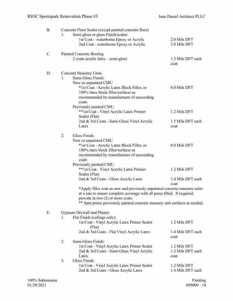
RIOC Sportspark Renovation Phase #3 June Daniel Architect PLLC
100% Submission Painting 01/29/2021 099000 - 14
B. Concrete Floor Sealer (except painted concrete floor) 1. Semi-gloss or gloss Finish/sealer: 1st Coat – waterborne Epoxy or Acrylic 2.0 Mils DFT 2nd Coat - waterborne Epoxy or Acrylic 2.0 Mils DFT C. Painted Concrete flooring
2 coats acrylic latex – semi-gloss 1.5 Mils DFT each coat
D. Concrete Masonry Units 1. Semi-Gloss Finish: New or unpainted CMU *1st Coat - Acrylic Latex Block Filler, or
100% latex block filler/surfacer as recommended by manufacturer of succeeding coats
8.0 Mils DFT
Previously painted CMU **1st Coat - Vinyl Acrylic Latex Primer-
Sealer (Flat) 1.2 Mils DFT
2nd & 3rd Coats - Semi-Gloss Vinyl Acrylic Latex
1.5 Mils DFT each coat
2. Gloss Finish: New or unpainted CMU *1st Coat - Acrylic Latex Block Filler, or
100% latex block filler/surfacer as recommended by manufacturer of succeeding coats
8.0 Mils DFT
Previously painted CMU **1st Coat - Vinyl Acrylic Latex Primer-
Sealer (Flat) 1.2 Mils DFT
2nd & 3rd Coats - Gloss Acrylic Latex 1.4 Mils DFT each coat
*Apply filler coat on new and previously unpainted concrete masonry units at a rate to ensure complete coverage with all pores filled. If required, provide in two (2) or more coats.
** Spot prime previously painted concrete masonry unit surfaces as needed. E. Gypsum Drywall and Plaster: 1. Flat Finish (ceilings only): 1st Coat - Vinyl Acrylic Latex Primer Sealer
(Flat) 1.2 Mils DFT
2nd & 3rd Coats - Flat Vinyl Acrylic Latex 1.4 Mils DFT each coat
2. Semi-Gloss Finish: 1st Coat - Vinyl Acrylic Latex Primer Sealer 1.2 Mils DFT 2nd & 3rd Coats - Semi-Gloss Vinyl Acrylic
Latex 1.3 Mils DFT each
coat 3. Gloss Finish: 1st Coat - Vinyl Acrylic Latex Primer Sealer 1.2 Mils DFT 2nd & 3rd Coats - Gloss Acrylic Latex 1.4 Mils DFT each

RIOC Sportspark Renovation Phase #3 June Daniel Architect PLLC
100% Submission Painting 01/29/2021 099000 - 15
coat F. Gypsum Drywall and Plaster: For use over existing oil based paints 1st Coat - 100% Acrylic Primer 1.2 mils DFT 2nd & 3rd Coats - Semi-Gloss Vinyl Acrylic
Latex 1.3 Mils DFT each
coat OR 2nd & 3rd Coats - Gloss Acrylic Latex 1.4 Mils DFT each
coat G. Ferrous Metal: 1. Flat Finish: Metal ceilings, jamb and head sections, coat
and hat rack, metal shelves.
*1st Coat - Modified Acrylic Rust Preventive Latex Primer
2.2 Mils DFT
2nd & 3rd Coats - Flat Vinyl Acrylic Latex 1.4 Mils DFT each coat
2. Semi-Gloss Finish: Grilles, access doors, frames, Steel Doors and
Frames, Trim, Parti-tions, Screens, Demountable Office Partitions,
*1st Coat - Modified Acrylic Rust Preventive Latex Primer
2.2 Mils DFT
2nd & 3rd Coats - Semi-Gloss Vinyl Acrylic Latex
1.5 Mils DFT each coat
3. Gloss Finish: *1st Coat - Modified Acrylic Rust Preventive
Latex Primer 2.2 Mils DFT
2nd & 3rd Coats - Gloss Acrylic Latex 1.4 Mils DFT each coat
* Provide full prime coat on new and previously unpainted surfaces. Spot prime previously painted surfaces, including shop-primed items, as needed. Items shop primed with modified alkyd equal to Tnemec 10-99 primer shall be touched up with same primer. See related specification sections.
H. Zinc-Coated Metal 1. Flat Finish: 1st Coat (New) - Modified Vinyl Acrylic
Latex Primer 2.2 Mils DFT
*1st Coat (Repaint) - Modified Acrylic Rust Preventive Latex Primer
2.2 Mils DFT
2nd & 3rd Coats - Flat Vinyl Acrylic Latex 1.4 Mils DFT each coat
2. Semi-Gloss Finish: Railings, wire-mesh work 1st Coat (New) - Modified Vinyl Acrylic
Latex Primer 2.2 Mils DFT
*1st Coat (Repaint) - Modified Acrylic Rust Preventive Latex Primer
2.2 Mils DFT

RIOC Sportspark Renovation Phase #3 June Daniel Architect PLLC
100% Submission Painting 01/29/2021 099000 - 16
2nd & 3rd Coats - Semi-Gloss Vinyl Acrylic Latex
1.5 Mils DFT each coat
3. Gloss Finish: 1st Coat (New) - Modified Vinyl Acrylic
Latex Primer 2.2 Mils DFT
*1st Coat (Repaint) - Modified Acrylic Rust Preventive Latex Primer
2.2Mils DFT
2nd & 3rd Coats - Gloss Acrlic Latex 1.4 Mils DFT each coat
* Spot prime as needed. I. Painted Woodwork and Hardboard 1. Semi-Gloss Enamel Finish: Wood window trim, Wood sill, chair rails, wood
door frames and trim, painted red or white birch, unless otherwise specified to be stained.
1st Coat - Vinyl Acrylic Latex Enamel Underbody
1.2 Mils DFT
2nd & 3rd Coats - Semi-Gloss Vinyl Acrylic Latex
1.5 Mils DFT each coat
2. Flat Finish: Pegboard, library display units, kindergarten
Furniture
1st Coat - Vinyl Acrylic Latex Enamel Underbody
1.2 Mils DFT
2nd & 3rd Coats - Flat Vinyl Acrylic Latex 1.3 Mils DFT each coat
J. Stained Woodwork (semi-transparent finish to match Project Architect's
sample)
1. Stained-Varnish Rubbed Finish: Stain Coat - Oil Type 0.9 Mils DFT 1st Coat - Cut Shellac Filler Coat -Paste wood filler (for open grain
wood)
2nd & 3rd Coats - Varnish 0.6 Mils DFT each coat
2.06 EXTERIOR PAINT SYSTEMS
A. New Ferrous Metal Structural steel, all ferrous metals, Steel Doors and frames, and
steel window trim.
1st Coat Touch up with epoxy Polyamide Paint 2nd Coat Polyamide Epoxy Paint
per SSPC-PS Guide 13.01 4.0 to 6.0 Mils DFT
3rd Coat (Top Coat)
Acrylic Aliphatic Polyurethane 1.5 to 2.0 Mils DFT
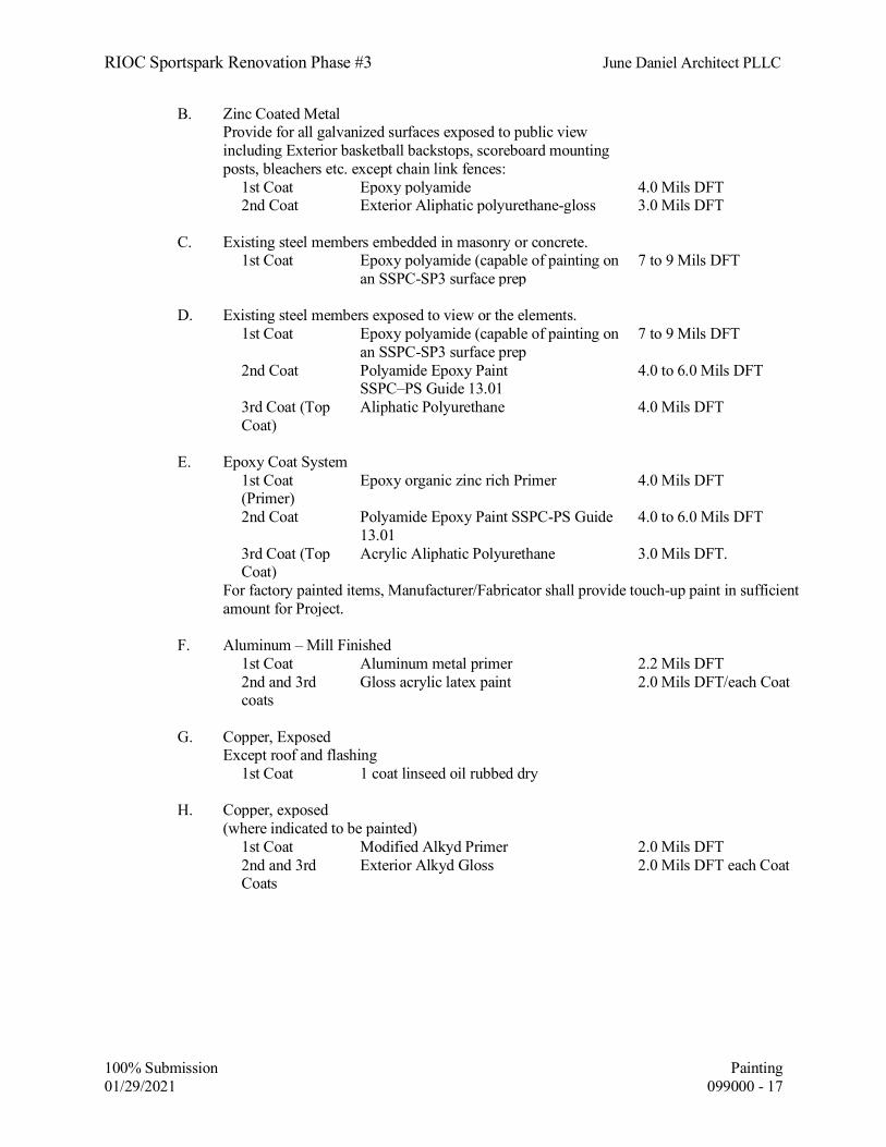
RIOC Sportspark Renovation Phase #3 June Daniel Architect PLLC
100% Submission Painting 01/29/2021 099000 - 17
B. Zinc Coated Metal Provide for all galvanized surfaces exposed to public view
including Exterior basketball backstops, scoreboard mounting posts, bleachers etc. except chain link fences:
1st Coat Epoxy polyamide 4.0 Mils DFT 2nd Coat Exterior Aliphatic polyurethane-gloss 3.0 Mils DFT C. Existing steel members embedded in masonry or concrete. 1st Coat Epoxy polyamide (capable of painting on
an SSPC-SP3 surface prep 7 to 9 Mils DFT
D. Existing steel members exposed to view or the elements. 1st Coat Epoxy polyamide (capable of painting on
an SSPC-SP3 surface prep 7 to 9 Mils DFT
2nd Coat Polyamide Epoxy Paint SSPC–PS Guide 13.01
4.0 to 6.0 Mils DFT
3rd Coat (Top Coat)
Aliphatic Polyurethane 4.0 Mils DFT
E. Epoxy Coat System 1st Coat
(Primer) Epoxy organic zinc rich Primer 4.0 Mils DFT
2nd Coat Polyamide Epoxy Paint SSPC-PS Guide 13.01
4.0 to 6.0 Mils DFT
3rd Coat (Top Coat)
Acrylic Aliphatic Polyurethane 3.0 Mils DFT.
For factory painted items, Manufacturer/Fabricator shall provide touch-up paint in sufficient amount for Project.
F. Aluminum – Mill Finished 1st Coat Aluminum metal primer 2.2 Mils DFT 2nd and 3rd
coats Gloss acrylic latex paint 2.0 Mils DFT/each Coat
G. Copper, Exposed Except roof and flashing 1st Coat 1 coat linseed oil rubbed dry H. Copper, exposed (where indicated to be painted) 1st Coat Modified Alkyd Primer 2.0 Mils DFT 2nd and 3rd
Coats Exterior Alkyd Gloss 2.0 Mils DFT each Coat

RIOC Sportspark Renovation Phase #3 June Daniel Architect PLLC
100% Submission Painting 01/29/2021 099000 - 18
PART 3 - EXECUTION 3.01 EXAMINATION
A. Verification of Conditions
l. The application of painter's finish to any surface shall be taken to indicate that the Contractor considers such surfaces suitable for a first-class finish.
2. Do not apply painter's finish in any locations until the Work of other Contractors
that might damage the new finish is completed.
3. Notify the Owner in writing regarding Work by others that does not provide a suitable surface for the new finish.
4. In case of dispute regarding the suitability of any surface, the Owner's decision
shall be final and conclusive upon all concerned.
5. Contractor shall check the compatibility of previously painted surface with the new coating by applying a test panel 4 foot wide x wall height. Allow test panel to dry thoroughly; verify proper adhesion before proceeding with painting Work.
3.02 PREPARATION AND APPLICATION - EXISTING BUILDING
A. Protection
1. In cases where the painting of surfaces involves removal or disturbance of existing paint and the paint is known or assumed to be lead-based paint, the following protection requirements shall apply:
a. All objects near or adjacent to the surface(s) to be painted shall be moved a
minimum of three feet away from that surface(s). Any immovable object, and the floor, within the three foot "work area" shall be covered with one layer of 6-mil polyethylene, sealed on all edges to prevent the penetration of dust and debris. If the ceiling is to be painted, all objects in the room and the floor of the room shall be covered in this manner.
b. All objects bordering the three-foot work area shall be completely covered
with clean cloths, heavy building paper or clean plastic covering.
c. If, during the removal of existing paint, the Contractor notices paint chips or other debris related to the ongoing work on objects beyond the border of the three foot work area, these objects shall be cleaned by HEPA vacuuming and wet-wiping and then covered as described in (b) above.
d. For exterior metal surfaces on the building or site the ground beneath the
work area shall be surrounded on all sides by a washable construction tarp or 10-mil polyethylene. The covering need not be airtight; however, it must be of adequate size and durability to completely enclose the work area and prevent the dispersal of any paint chips or dust during paint removal activities. Any dust and debris shall be contained in the work area

RIOC Sportspark Renovation Phase #3 June Daniel Architect PLLC
100% Submission Painting 01/29/2021 099000 - 19
and shall be removed immediately upon generation. Protect from damage landscaping, paving, and other improvements near the building. Protect and seal all windows and openings within the work area with a minimum of 1 layer of 6-mil polyethylene sheeting.
e. The protection shall remain in place during all paint removal activities.
f. All protection is to be carefully removed, cleaned or discarded after
painting is complete.
2. In cases where the painting of surfaces does not involve the removal or disturbance of existing paint or the paint is not lead-based as determined by testing by the Owner, the following protection requirements shall apply:
a. In each area to be painted, cover and protect furniture, equipment and
floors from damage with clean cloths, heavy building paper or clean plastic covering secured in place. All protection is to be carefully removed, cleaned or discarded after painting is complete.
B. Removal of Existing Work
1. Remove wire guards, screens, grilles and similar items as necessary to paint
properly all surfaces, windows and doors, behind these items.
a. These items shall be HEPA vacuumed and wet-cleaned once removed. Once cleaned, the items shall be placed on 6-mil polyethylene sheeting (or equivalent) and covered with a second layer of 6-mil polyethylene sheeting.
b. If paint is to be removed from these items, the contractor shall ensure that
the items are taken to a separate, non-occupied space prior to scraping and repainting.
2. Remove and paint behind pictures, signs, shades, drapes, furniture, cabinets,
lockers and similar items that are not secured to walls.
3. Unless otherwise specified, radiators, convectors, univents need not be removed providing all visible surfaces of these items and visible surfaces behind them are properly painted.
4. Carefully mark removed work for identification and replace in the original location
unless otherwise directed.
C. Surface Preparation
1. Gently wet mist the surface to be scraped with water, then remove all loose paint with scraper and putty knife.
2. Sand existing surfaces to dull sheen and gloss. Before sanding, wet mist the area to
be sanded. (Power sanding without a HEPA-filtered vacuum recovery system is not allowed).

RIOC Sportspark Renovation Phase #3 June Daniel Architect PLLC
100% Submission Painting 01/29/2021 099000 - 20
3. Remove dust by washing with water, using damp sponge or cloth.
4. After washing, spot prime grease and water stains; magic markers marks, crayon
marks, lipstick marks, etc.; with a quick-drying alcohol base primer sealer to prevent bleeding.
5. Fill all cracks and holes with appropriate filler material, wet mist and sand flush
with adjacent surfaces and spot prime. (Power sanding without a HEPA-filtered vacuum recovery system is not allowed).
6. Existing paint that was not removed with scraper and which appears to be sound
shall receive spackling compound around perimeter high spots and feathered out so that surface is smooth. Repair gouges created by the scraping process and other imperfections in the existing surface with spackling compound to provide a smooth, even finished surface.
7. Apply number of finish coats specified herein or as many as may be necessary to
obtain the proper finish and completely cover the substrate. 8. Cement Plaster: Coat surfaces to be patched with an approved bonding agent.
Patch with an approved mortar patching mix and finish to match texture of adjacent surfaces.
10. Existing Metal
a. Prepare surfaces as indicated in paragraph 3.02.C, subparagraphs 1, 2, 3, 4,
above.
b. Machine tool clean exposed steel to an SSPC-SP3 surface preparation.
b. For steel surfaces exposed to view, repair defects in surfaces to provide for an even plane in the new finish. Use auto-body filler to even out surface and sand smooth.
11. Wood Sash: Clean and oil pulley stiles of wood sash with one coat of stained,
boiled linseed oil at completion of painting of sash.
12. Glazing Repairs
a. Cut out loose and cracked putty on doors and windows. Replace cut out and missing putty with elastic glazing compound. If the putty contains asbestos, the Contractor shall abate the putty in accordance with the procedures specified in Section 02081 - Asbestos Abatement.
b. Prime Surfaces before applying glazing compound.

RIOC Sportspark Renovation Phase #3 June Daniel Architect PLLC
100% Submission Painting 01/29/2021 099000 - 21
3.03 APPLICATION
A. General
1. No Work shall be performed where cement or plaster is being applied or is in the process of drying.
2. No Work shall be performed in spaces that are not broom clean and free of dust
and waste.
3. Apply paint materials to produce smooth finished surfaces, free of brush or roller marks, drops, runs, or sags.
4. Paint materials shall be kept at a proper and uniform consistency. Paint shall be
applied to achieve Dry film thickness (DFT) as recommended by manufacturer or to achieve the minimum thickness for paint systems as listed in Articles 2.06 and 2.07.
5. Thin only when necessary to achieve best results.
6. Thinners shall be material recommended by manufacturer of paint, and in quantity
as recommended.
7. Excessive use of thinner as indicated by variation in absorption, lack of "hide", thickness of dry film, mottled or streaky coat, shall be cause for rejection. Correct as directed.
8. Thinning of varnish or aluminum paint prohibited.
9. Apply all coats with brush or roller, varying slightly the color of succeeding coats.
Spraying will not be permitted. a. If recommended by manufacturer, 100% acrylic resin concrete block filler
may be spray applied and shall be backrolled as necessary to work material into substrate surface.
10. Brush out or roll on first or prime coat; work well into surface.
11. Each coat shall be inspected, approved and dry before proceeding with additional
coats.
12. Allow at least 48 hrs for enamels and exterior paint to dry.
13. The surfaces of interior woods and metals shall be sanded or rubbed between coats to assure smooth finish and proper adhesion of subsequent coats.
14. Avoid lapping of paint on glass, hardware, or other adjoining surfaces.
15. Apply no paint to operating units where sliding contact of metals is necessary for
proper functioning of unit.

RIOC Sportspark Renovation Phase #3 June Daniel Architect PLLC
100% Submission Painting 01/29/2021 099000 - 22
16. Painting is not required on walls or ceilings in concealed and inaccessible areas.
17. Moving parts of operating units will not require finish painting unless otherwise required.
18. Do not paint over any code-required labels, such as Underwriter's Laboratories and
Factory Mutual, or any equipment identification, performance rating, name or nomenclature plate.
19. Finish doors on tops, bottoms and side edges same as exterior faces.
20. For painting over existing oil based paint: Prepare surface by lightly sanding the
surface to be painted.
3.04 FIELD QUALITY CONTROL
A. The Owner reserves the right to require the following material testing procedures at any time, and any number of times during period of field painting:
1. Measurement of dry film thickness (DFT) by use of a dry film thickness gauge in
accordance with use and calibration requirements of Structural Steel Painting Council [SSPC], "Method of Measurement of Dry Paint Thickness with Magnetic Gauges".
2. Engage services of an independent testing laboratory, recommended by the Owner,
to sample paint being used. Samples of materials delivered to construction site will be taken, identified and sealed, and certified in presence of Contractor
3. Testing laboratory will perform appropriate tests for any or all of the following
characteristics: Abrasion resistance, apparent reflectivity, flexibility, washability, absorption, accelerated weathering, dry opacity, accelerated yellowness, recoating, skinning, color retention, alkali resistance and quantitative materials analysis.
4. If test results show that material being used does not comply with specified
requirements, Contractor shall be directed to stop painting Work, and remove non-complying paint; repaint surfaces coated with rejected paint; remove rejected paint from previously painted surfaces if, upon repainting with specified paint, the two coatings are non-compatible.
a. If the samples do not comply with requirements of the Specifications, costs
of testing and remediation of rejected work shall be borne by Contractor.
b. If the tests find that the samples do comply with the requirements of the Specifications, the cost of the testing will be borne by the Owner.

RIOC Sportspark Renovation Phase #3 June Daniel Architect PLLC
100% Submission Painting 01/29/2021 099000 - 23
3.05 CLEANING
A. General
Contractor shall clean-up behind each paint crew such that painting and clean-up will be a continuous uninterrupted operation. The practice of one general clean-up after completion of all painting will be strictly prohibited. This clean-up will include, but not be limited to the following:
1. Remove spots or defacement resulting from Work of this Section.
2. Retouch all damaged surfaces to leave Work in perfect finished condition.
3. If spots or defacement cannot be satisfactorily removed and retouched, re-finish the
surfaces as directed.
4. Within the three foot work area created for removal and painting where existing paint is known or assumed to be lead-based all objects and surfaces shall be thoroughly HEPA vacuumed, wet-cleaned and HEPA vacuumed again. In rooms where the ceiling has been painted all surfaces and objects in the room shall be cleaned in this manner.
5. The contractor shall ensure that the objects and surfaces under protective covering
are free of any dust or debris created during painting activities. If necessary, these objects and surfaces shall be wet cleaned and HEPA vacuumed.
6. The contractor shall conduct any cleaning deemed necessary by the independent
environmental consultant.
7. Free all operating units of painted materials and leave them clean and in proper working order.
8. Remove from premises all surplus paint materials, debris and any other rubbish
resulting from the Work.
9. Leave storage space clean and in condition required for equivalent spaces in project.
3.06 PROTECTION
A. Provide caution tape and/or locked entryways during paint removal activities in existing buildings to prevent access to the work area from unauthorized personnel.
B. Provide "Wet Paint" signs to protect newly-painted finishes. Remove temporary protective
wrappings provided by others for protection of their Work after completion of painting operations.
C. At the completion of Work of other trades, touch-up and restore all damaged or defaced
painted surfaces as directed by the Owner.

RIOC Sportspark Renovation Phase #3 June Daniel Architect PLLC
100% Submission Painting 01/29/2021 099000 - 24
3.07 DISPOSAL OF PAINTED WASTE AND DEBRIS FROM EXISTING BUILDINGS
A. Testing
Perform Toxicity Characteristic Leaching Procedure (TCLP) testing of all painted waste and debris generated from existing painted objects and surfaces.
B. Storage and Disposal
Storage and disposal shall be in accordance with Specifications Section S01900 - Existing Premises Work, Article titled "Disposal of Painted Waste and Debris".
END OF SECTION

RIOC Sportspark Renovation Phase #3 June Daniel Architect PLLC
100% Submission IDENTIFYING DEVICES 01/29/2021 101410 - 1
SECTION 101410 - IDENTIFYING DEVICES
PART 1 -GENERAL 1.01 DESCRIPTION OF WORK A. Provide identifying device Work as indicated on the Drawings and as specified herein,
including but not limited to cast metal letters, metal logo, etched zinc signs.
B. Locations of identifying devices shall be as indicated on Drawings and as specified herein. The terms “signs” and “plates” are used interchangeably.
1.02 REFERENCES
A. References and industry standards listed in this Section are applicable to the Work. Unless more restrictive criteria or differing requirements are explicitly stated in the Specifications, or mandated by governing codes or regulations, the recommendations, suggestions, and requirements described in the referenced standards shall be deemed mandatory and applicable to the Work.
B. American National Standards Institute, ANSI A117.1, Accessible and Usable Buildings
and facilities
C. Copper Development Association (CDA)
D. National Association of Architectural Metal Manufacturers (NAAMM)
E. Americans with Disabilities Act (ADA), Accessibility Guidelines,
F. New York City Building Code (2014), Section BC 1030 - Signage. 1.03 SUBMITTALS
A. Schedule and layouts for all signs, indicating sign type, material, location, text, text letter style, inserts, dimensions, color, Braille transcriptions, and other pertinent information. Submit a photocopy proof of each zinc sign, complete with Braille.
All Braille transcriptions shall be reviewed for accuracy by a Braille transcriber or
proofreader holding a certificate issued by the Braille Development Section, National Library Service for the Blind and Physically Handicapped, Library of Congress. Submit proof of Library of Congress certification together with the reviewed Braille transcriptions.
B. Cast Letters
Shop Drawing of full text at scale of 3"= 1'-0"; indicate letter style, sizes, spacing and method of securing.

RIOC Sportspark Renovation Phase #3 June Daniel Architect PLLC
100% Submission IDENTIFYING DEVICES 01/29/2021 101410 - 2
C. Samples 1. Zinc Signs: Submit sample of each type, indicating colors, finishes; complete
with acrylic lenses, paper inserts; showing letter style, size, method of attachment, and other pertinent characteristics.
2. Cast Letters: Submit one full size letter for approval. Approved letter may be
used for the Project. 3. Painted Aluminum signs: Submit sample of each type, indicating colors, finishes;
showing letter style, size, method of attachment, and other pertinent characteristics.
D. Project Closeout Submittals 1. Floor Diagram Signs: Submit 2 extra reproducible graphic copies of each floor
diagram. 2. Touch-up coating kit for zinc signs, to match the original “Brushed Aluminum”
color coating; each container labeled by coating manufacturer. Kit shall consist of 3 quarts paint, 1 quart catalyst, 1 quart additive for brush application, 1 five-ounce clear graduated mixing container, 2 touch-up brushes, 1 pint brush cleaning solvent, 4 sheets of abrasive paper for removing scratches, and complete instructions for use of the kit.
In addition, provide one pint of touch-up paint of each color used for text and
background, other than the “Brushed Aluminum” color. 3. Graffiti cleaning solvent for zinc signs, capable of removing permanent marker
with minimal effect on sign finish, as recommended by sign coating manufacturer; six 1-pint containers.
4. Provide four Torx Pin-Head drivers for each size required.
5. Provide 60 extra Torx Pin-Head mounting screws of each size used. 6. Provide one 300-inch roll of Scotch double-stick photo and document tape, in
dispenser.
1.04 QUALITY ASSURANCE
A. Work of this Section shall be performed by firms experienced in metal casting, signage manufacture and installation of these items.
1.05 DELIVERY, STORAGE, AND HANDLING
A. Deliver, store and handle products of this Section as recommended by manufacturer or fabricator to protect from damage.

RIOC Sportspark Renovation Phase #3 June Daniel Architect PLLC
100% Submission IDENTIFYING DEVICES 01/29/2021 101410 - 3
PART 2 - PRODUCTS 2.01 COPPER POLISHED LETTERS
A. Provide copper polished letters with text and locations as indicated on Drawings.
1. Material: Copper brass alloy.
2. Finish: Copper Polish
3. Letter Size: Height 17" Depth 1/2"
4. Letter Style: Standard Block
5. Mounting: Concealed Studs, with stainless steel spacers ( 1 " depth).
B. Manufacturers
1. Impactsign.com; LaGrange IL 60525
2. Andco Industries Corp., Greensboro, NC 27410
3. Matthews International Corp., Pittsburgh, PA 15212
4. Signs and Decal Corp., Brooklyn, NY 11211 2.02 CUT POLISH COPPER LOGO A. Provide cut polish copper logo as indicated on Drawings.
1. Material: Copper brass alloy.
2. Finish: Copper Polish.
3. Logo Size: Height 2'-0" Depth 1/2"
4. Logo: As indicated on drawings.
5. Mounting: Concealed Studs, with stainless steel spacers ( 1 " depth).
B. Manufacturers
1. Impactsign.com; LaGrange IL 60525 2. The Southwell Co., San Antonio, TX 78291
3. Andco Industries Corp., Greensboro, NC 27410

RIOC Sportspark Renovation Phase #3 June Daniel Architect PLLC
100% Submission IDENTIFYING DEVICES 01/29/2021 101410 - 4
4. Matthews International Corp., Pittsburgh, PA 15212
5. Signs and Decal Corp., Brooklyn, NY 11211.
2.03 ROOM NAME PLATES AND NUMBER PLATES
A. Provide etched zinc room name plates and number plates with text and location as indicated on Drawings and as specified herein.
1. Material: .125” thick zinc, unless indicated otherwise.
2. Size: As shown on drawings
3. Finish: Acrylic polyurethane enamels 4. Letter Style: Helvetica Regular 5. Mounting: Countersunk tamper-resistant Torx Pin-Head flat head screws and
construction adhesive, unless indicated otherwise. Signs less than 75 in2 in area that are located on ceramic tile wall finish shall be mounted with double face acrylic foam tape and construction adhesive, and shall be fabricated without screw holes.
2.04 ETCHED ZINC SIGNS, GENERAL Provide room signs, and other etched zinc signs as specified herein. A. Signs and plates specified herein as zinc shall be chemically etched zinc with raised lettering
and pictograms as indicated on the Drawings and as specified. Background area shall be etched to a depth of .032” to .040”, to produce raised tactile text, pictograms, and Braille. Signs shall be one-piece solid zinc plate .125” thick prior to etching, unless specified otherwise. For 2”x4” room number plates to be installed on door frame heads the zinc plate shall be .064” thick prior to etching. For signs with changeable inserts, the tactile text portion of the sign shall be a .064” thick zinc plate, permanently laminated to an aluminum extrusion or precision routered aluminum plate for a total thickness of .375” as indicated on the Drawings. Surfaces, edges and corners shall be eased and polished as necessary to eliminate all roughness and sharpness.
B. Unless indicated otherwise, zinc and aluminum surfaces, including the sign face, edges, area
behind inserts, and exposed screw heads, shall receive spray painted Matthews acrylic polyurethane enamel, for a uniform eggshell-matte finish; Matthews Paint Company color name “Brushed Aluminum”, color number 41342SP. Raised letters, numerals, and pictograms shall receive black acrylic polyurethane enamel unless indicated otherwise. Prepare and prime metal surfaces prior to finish paint coating as recommended by the paint manufacturer. All finishes shall be baked on as recommended by the coating manufacturer. Exposed screw heads shall be painted without clogging drive sockets.

RIOC Sportspark Renovation Phase #3 June Daniel Architect PLLC
100% Submission IDENTIFYING DEVICES 01/29/2021 101410 - 5
C. Where finish is specified as red letters on white background, or other multi-color combination, surfaces shall be painted with polyurethane acrylic enamel paint. If the sign is exposed to the outdoors the paint shall be exterior rated, containing UV inhibitor.
D. Provide Grade II Braille for all signs unless indicated otherwise, accurately transcribed from
letter and numeral characters. E. Drilled and countersunk mounting holes, unless indicated otherwise. F. Fabricate signs to comply with requirements of Americans with Disabilities Act (ADA)
and ANSI A117.1. G. Manufacturers
1. Dixie Graphics, Nashville, TN 37211. Phone 615 832-7000. 2. Dutton Architectural, Chattanooga, TN. Phone 423 752-1300. 3. Advance Corp., Braille-Tac Div., St. Paul, MN 55101. Phone 651 771-9297. 4. Etchcraft, Portland, OR 97219. Phone 800 356-7998. 5. Signs and Decal Corp., Brooklyn, NY 11211. Phone 718 486-6400.
2.05 SIGNS FOR SYMBOLS OF ACCESSIBILITY A. Fabricate etched zinc signs to comply with the requirements of Americans with
Disabilities Act (ADA), and ANSI A117.1 B. Provide signs of type and with text and at locations as indicated on the Drawings. C. Material: .125” zinc. Finish colors as indicated on the Drawings. Acrylic polyurethane
enamels, exterior rated where applicable.
D. Mounting: Countersunk tamper-resistant Torx Pin-Head flat head screws, and construction adhesive unless indicated otherwise. Signs less than 75 in2 in area that are located on ceramic tile wall finish shall be mounted with double face acrylic foam tape and construction adhesive, and shall be fabricated without screw holes.
2.06 MISCELLANEOUS MATERIALS
A. Construction Adhesive
All adhesives to be used on the building interior shall be low V.O.C. in accordance with the requirements of Section G01600.
1. Henkel Loctite “PL” Premium Advanced Polyurethane Construction Adhesive

RIOC Sportspark Renovation Phase #3 June Daniel Architect PLLC
100% Submission IDENTIFYING DEVICES 01/29/2021 101410 - 6
2. Liquid Nails “LN-950” Polyurethane Construction Adhesive.
B. Double face acrylic foam tape: 3M VHB Tape 4950, 1/2” wide.
PART 3 - EXECUTION 3.01 INSPECTION
A. Install no Work until surfaces on which Signage, Seals, Tablets, and other Work for this Section are to be placed and attached are completed and free of defects.
3.02 PREPARATION
A. Surfaces to receive placement of Work of this Section shall be clean and dry. 3.03 INSTALLATION
A. Install signage and other Work of this Section level and plumb, secured to substrate as detailed on Drawings, as specified, and as recommended by manufacturer. Use concealed attachments where possible for cast letters and plaques, and tamper-resistant fasteners and adhesive for other signs.
B. Mounting Locations
Mount all signs and other Work of this Section as indicated on Drawings and as specified herein.
C. Mounting
1. The Contractor shall be responsible for the following:
a. Coordinating the location and size of metal grounds concealed behind wallboard, to receive the fasteners for the signs.
b. Marking the location of all sign fasteners on the wall.
c. Drilling the pilot holes. d. Supplying the specified fasteners, masonry anchors and drivers.
e. Installing the signs.
2. Zinc signs shall be secured to masonry walls with construction adhesive in
addition to tamper-resistant Torx Pin-Head, diameter #10, x 2” long, flat head countersunk masonry anchors. Sand and roughen substrate to receive adhesive as per manufacturer’s instructions. Interior anchors to be zinc plated, exterior anchors to be hot dip galvanized.

RIOC Sportspark Renovation Phase #3 June Daniel Architect PLLC
100% Submission IDENTIFYING DEVICES 01/29/2021 101410 - 7
3. Zinc signs shall be secured to partitions constructed of wallboard, metal studs, and metal grounds, with construction adhesive, in addition to tamper-resistant Torx Pin-Head, diameter #10, flat head countersunk zinc plated sheet metal screws. Drill pilot holes if required. Provide screw length sufficient to penetrate at least 1/2" past wall finish materials, wallboard, and metal grounds. Prepare substrate to receive adhesive and apply as per manufacturer’s instructions.
Signs less than 75 in2 in area that are located on ceramic tile wall finish shall be
mounted with double face acrylic foam tape and construction adhesive, and shall be fabricated without screw holes. These signs shall be mounted with double face acrylic foam tape and construction adhesive. Apply tape around perimeter of the back of sign, leaving 1” open on each side, and adhesive covering the remainder of the back. Brace sign until securely adhered.
4. 2”x4” zinc room number plates shall be secured to door frame heads with
tamper-resistant Torx Pin-Head, diameter #8, button head zinc plated sheet metal screws.
5. Furnish and install fasteners in such manner that there are no exposed sharp
edges in the completed installation. Exposed screw heads shall be painted to match sign, without clogging drive sockets.
6. Door mounted aluminum signs shall be secured to substrates with very high bond
double-sided tape or structural adhesive as recommended by the marking manufacturer to prevent unauthorized loosening or removal.
3.04 FIELD QUALITY CONTROL
A. Cooperate with the Special Inspector performing Special Inspection testing. 3.05 CLEAN-UP AND PROTECTION
A. Clean surfaces of Work of this Section.
B. Remove debris resulting from Work of this Section from Work Area.
C. Remove protection covers and protect Work until Project Completion.
END OF SECTION

RIOC Sportspark Renovation Phase #3 June Daniel Architect PLLC
100% Submission Toilet Compartments 01/29/2021 102100 - 1
SECTION 102100 - TOILET COMPARTMENTS PART 1 - GENERAL 1.01 DESCRIPTION OF WORK
A. Provide floor-mounted overhead braced solid polymer, or solid phenolic toilet
compartments and privacy screens as indicated on the Drawings and as specified herein.
B. Provide privacy screens.
C. Provide shower and dressing compartments. D. Provide solid plastic vanity
E. Provide all accessories and hardware required for a complete installation.
1.02 REFERENCES
A. References and industry standards listed in this Section are applicable to the Work. Unless more restrictive criteria or differing requirements are explicitly stated in the Specifications, or mandated by governing codes or regulations, the recommendations, suggestions, and requirements described in the referenced standards shall be deemed mandatory and applicable to the Work.
B. American Society for Testing and Materials (ASTM).
C. National Fire Protection Association (NFPA) 1.03 SUBMITTALS
A. Product Data
Submit manufacturer's detailed technical data for materials, fabrication, and installation, including catalog cuts of anchors, hardware, fastenings, and accessories.
B. Shop Drawings
1. Submit shop drawings for fabrication and erection of Toilet Partition assemblies
not fully described by product drawings, including plans, elevations, details of fastening devices and accessory reinforcing plates, templates, and instructions for installation of anchorage devices built into other work.
2. Prior to installation of adjacent drywall work submit elevations, details, and
templates for locations of steel grounds to be furnished and installed in drywall partitions under Section 09260-Gypsum Board Assemblies. Grounds shall receive fasteners at all locations where brackets and other devices supporting the work of this Section are attached to the wall.

RIOC Sportspark Renovation Phase #3 June Daniel Architect PLLC
100% Submission Toilet Compartments 01/29/2021 102100 - 2
C. Samples Submit color chart with manufacturer's full range of Standard colors. Provide 4" square
samples of color and finish of materials along with manufacturer's hardware samples, upon request.
D. Certification
Submit certification that materials furnished comply with requirements specified.
E. Tests Submit independent laboratory test reports, naming the panel material manufacturer and
the toilet compartment manufacturer:
1. Test report for flame spread shall be less than one-year old. 2. Test report for burning toxicity shall be less than four years old.
F. Maintenance Instructions
Provide manufacturer's printed Instructions for maintenance of installed Work.
G. Warranty Manufacturer’s 15-year written Warranty 1.04 QUALITY ASSURANCE
A. Take field measurements prior to preparation of Shop Drawings and fabrication, where possible, to ensure proper fitting of Work. Allow for adjustments within specified tolerances in taking of field measurements. Provide inserts and anchorages built into other Work for installation of toilet partitions and related Work; coordinate delivery with other Work to avoid delay.
1.05 DELIVERY, STORAGE AND HANDLING
A. Deliver, store, and handle compartments as recommended by manufacturer to protect from damage.
1.06 MANUFACTURER'S WARRANTY
A. Written, fifteen years, against breakage, corrosion and delamination; replaced without charge, excluding labor.

RIOC Sportspark Renovation Phase #3 June Daniel Architect PLLC
100% Submission Toilet Compartments 01/29/2021 102100 - 3
PART 2 - PRODUCTS 2.01 MANUFACTURERS
A. Solid Polymer (HDPE) Compartments
1. Scranton Products, Scranton, PA 18505. Acceptable Manufacturer: Scranton Products, which is located at: 801 E. Corey St.; Scranton, PA 18505; Toll Free Tel: 800-445-5148; Fax: 855-376-6161; Email:request info ([email protected]); Web:www.scrantonproducts.com
1. Fabricator: Santana Toilet Partitions. 2. Fabricator: Comtec Toilet Partitions. 3. Fabricator: Capitol Toilet Partitions.
B. Or Approved Equal.
2.02 MATERIALS – SOLID PLASTIC TOILET COMPARTMENTS
A. Basis of Design: Hiny Hiders Toilet Partitions as manufactured by and supplied by Scranton Products.
1. Style: Floor mounted overhead-braced toilet compartments.
B. Doors, Panels, and Pilasters: 1 inch (25 mm) thick with all edges rounded to a radius. Mount doors and dividing panels based on height of specified system.
1. Door and Panel Height: 66 inches (1676 mm). 2. Aluminum heat sink fastened to bottom edges. 3. Door Design: Traditional 2600. 4. Door Design: Traditional 2800. 5. Door Design: Modern 3000. 6. Door Design: Modern 3200. 7. Door Design: Modern 3800. 8. Door Design: Modern 4000. 9. Door Design: Two panel side panel design. 10. Panel Edge: Standard. 11. Panel Edge: Shiplap. 12. Pilasters: 82 inches (2083 mm) high and fastened to floor.
C. Panel Color: Traditional Series. Color: TBD
D. Panel Color: Bold Series. Color: TBD
E. Panel Color: Warm Series. Color: TBD
F. Panel Color: Metallic Series. Color: TBD
G. Pilaster Shoes: 3 inches (76 mm) high one-piece molded HDPE. Secured to pilasters with a stainless steel tamper resistant Torx head sex bolt.
1. Pilaster Plastic Shoe Color: TBD
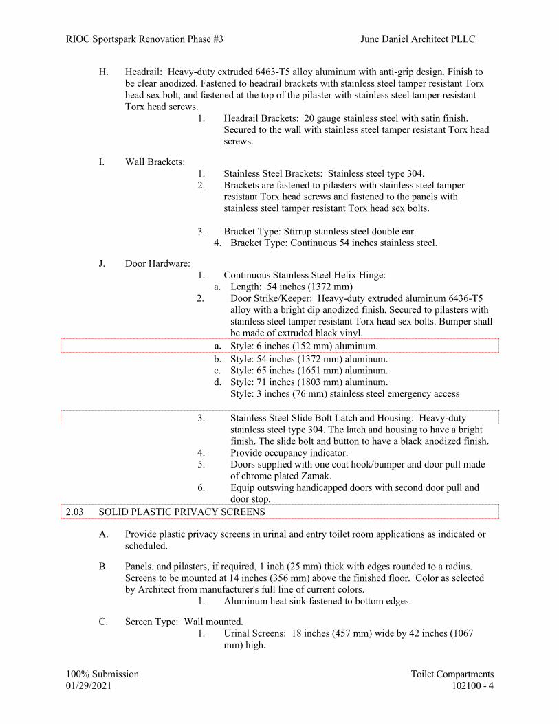
RIOC Sportspark Renovation Phase #3 June Daniel Architect PLLC
100% Submission Toilet Compartments 01/29/2021 102100 - 4
H. Headrail: Heavy-duty extruded 6463-T5 alloy aluminum with anti-grip design. Finish to be clear anodized. Fastened to headrail brackets with stainless steel tamper resistant Torx head sex bolt, and fastened at the top of the pilaster with stainless steel tamper resistant Torx head screws.
1. Headrail Brackets: 20 gauge stainless steel with satin finish. Secured to the wall with stainless steel tamper resistant Torx head screws.
I. Wall Brackets: 1. Stainless Steel Brackets: Stainless steel type 304. 2. Brackets are fastened to pilasters with stainless steel tamper
resistant Torx head screws and fastened to the panels with stainless steel tamper resistant Torx head sex bolts.
3. Bracket Type: Stirrup stainless steel double ear.
4. Bracket Type: Continuous 54 inches stainless steel.
J. Door Hardware: 1. Continuous Stainless Steel Helix Hinge:
a. Length: 54 inches (1372 mm) 2. Door Strike/Keeper: Heavy-duty extruded aluminum 6436-T5 alloy with a bright dip anodized finish. Secured to pilasters with stainless steel tamper resistant Torx head sex bolts. Bumper shall be made of extruded black vinyl.
a. Style: 6 inches (152 mm) aluminum. b. Style: 54 inches (1372 mm) aluminum. c. Style: 65 inches (1651 mm) aluminum. d. Style: 71 inches (1803 mm) aluminum.
Style: 3 inches (76 mm) stainless steel emergency access
3. Stainless Steel Slide Bolt Latch and Housing: Heavy-duty stainless steel type 304. The latch and housing to have a bright finish. The slide bolt and button to have a black anodized finish. 4. Provide occupancy indicator. 5. Doors supplied with one coat hook/bumper and door pull made of chrome plated Zamak. 6. Equip outswing handicapped doors with second door pull and door stop.
2.03 SOLID PLASTIC PRIVACY SCREENS
A. Provide plastic privacy screens in urinal and entry toilet room applications as indicated or scheduled.
B. Panels, and pilasters, if required, 1 inch (25 mm) thick with edges rounded to a radius. Screens to be mounted at 14 inches (356 mm) above the finished floor. Color as selected by Architect from manufacturer's full line of current colors.
1. Aluminum heat sink fastened to bottom edges.
C. Screen Type: Wall mounted. 1. Urinal Screens: 18 inches (457 mm) wide by 42 inches (1067
mm) high.

RIOC Sportspark Renovation Phase #3 June Daniel Architect PLLC
100% Submission Toilet Compartments 01/29/2021 102100 - 5
D. Wall Brackets: Extruded PVC plastic. Fastened to the panel/pilaster with stainless steel tamper resistant torx head screws and fastened to wall with stainless steel tamper resistant torx head sex bolts.
1. Length of Wall Brackets: 41 inches (1041 mm). 2. Bracket Color: TBD
2.04 SOLID PLASTIC SHOWER AND DRESSING COMPARTMENTS
A. Plastic privacy screens in shower room applications as indicated or scheduled.
B. Panels and Pilasters: 1 inch (25 mm) thick with edges rounded to a radius. Mount screens at 14 inches (356 mm) above the finished floor. Color as selected by Architect from manufacturer's full line of current colors.
1. Recycled content: Minimum 25 percent.
C. Type: Floor mounted pilaster supported screen. 1. Panel Screens: 76 inches (1930 mm) high. 2. Headrail Brackets: 20 gauge stainless steel with a satin finish.
Secured to the wall with stainless steel tamper resistant Torx head screws.
3. Pilaster Sleeves: Type 304, 20 gauge stainless steel. 3 inches (76 mm) high. Secured to pilaster with stainless steel tamper resistant Torx head sex bolt.
4. Wall Brackets: Continuous, heavy-duty 6463-T5 alloy aluminum. Bright dip anodized finish. Fastened to panel/pilaster with stainless steel tamper resistant Torx head sex bolts.
5. Shower Curtains (WxH): 42 x 72 inches (1067 x 1829 mm), white non PVC, hung with aluminum curtain hooks with self-lubricating Delrin slides.
2.05 SOLID PLASTIC VANITY
A. Provide vanities in sizes and applications as indicated or scheduled.
B. Tops, Splashes, Skirts, End and Center Supports: 1 inch (25 mm) thick with all edges rounded to a radius. Screens shall be mounted at 14 inches (356 mm) above the finished floor. Color as selected by Architect from manufacturer's full line of current colors.
C. Pilaster sleeves shall be 3 inches (76 mm) high one-piece molded HDPE secured to the pilaster with a stainless steel tamper resistant Torx head sex bolt.
D. Attachment Brackets: 16 inches (406 mm) long, heavy duty extruded aluminum with bright dip anodized finish.
2.06 ANCHORAGE AND REINFORCEMENT
A. Anchorages and fasteners: Manufacturer's Standard, theft-proof exposed fasteners of stainless steel (Type 304), finished to match hardware, with 1/4" tamper-proof sex bolts.

RIOC Sportspark Renovation Phase #3 June Daniel Architect PLLC
100% Submission Toilet Compartments 01/29/2021 102100 - 6
B. Reinforcement for paper holders: Provide as recommended by the Toilet Compartment manufacturer, for vandal resistant mounting.
C. Reinforcement for grab bars: Provide as recommended by Toilet Compartment
manufacturer.
Note: Grab bar installation shall sustain a force of at least 250 lbs. at any point from any direction.
D. Grab Bar Support: Panels shall be capable of supporting grab bars with 250 lb. Force at
any point in any direction. PART 3 – EXECUTION 3.01 PREPARATION & INSTALLATION
A. Installation at Floors:
Anchor pilasters to deck as recommended by compartment manufacturer. Anchors shall penetrate structural floor no less than 2 inches.
B. Attach Continuous Wall Brackets and other supporting devices to wall with the following:
1. At solid masonry: 1/4” diameter x 3½” long Stainless Steel expansion shields at 9”
O.C. vertical spacing.
2. At cavity masonry: 1/4” diameter x required length Stainless Steel toggle bolts at 9” O.C. vertical spacing.
3. At drywall: Secure wall brackets and all other supporting devices to wall with
#14 stainless steel vandal resistant torx head with pin sheet metal screws. Screws shall be of sufficient length to penetrate wall finish, drywall panels and metal grounds and extend at least 1/2” through metal grounds.
C. Comply with manufacturer’s recommended procedures and installation sequence. Install
partitions rigid, straight, plumb, and level. Provide clearances not more than 1/2” between pilasters and panels, panels and walls, and not more than 1” between pilasters and walls. No evidence of drilling, cutting and patching shall be visible in finished work.
3.02 ACCESSORIES
A. Mount accessories to partition units in accordance with manufacturer’s instructions.

RIOC Sportspark Renovation Phase #3 June Daniel Architect PLLC
100% Submission Toilet Compartments 01/29/2021 102100 - 7
3.03 CLEANING
A. Remove protective masking and clean exposed surfaces of toilet partitions, using materials and methods recommended by manufacturer. Provide protection as necessary to prevent damage during remainder of construction period.
END OF SECTION

RIOC Sportspark Renovation Phase #3 June Daniel Architect PLLC
100% Submission Demountable Partition 01/29/2021 102200 - 1
SECTION 102200 - DEMOUNTABLE PARTITION Part 1 - GENERAL 1.01 RELATED DOCUMENTS
A. Architectural drawings and sections for this Contract, including the Conditions of the
Contract and Division 01 Specification Sections B. Wood Doors – Division 08 C. Architectural Hardware – Division 08 D. WDMA Standard for Wood Doors 2010
1.02 SUMMARY
A. Furnish and install Acme System 50 by Inscape Architectural Interiors. Vertical mullions shall be 1-1/2” wide, 2½” deep. Base and top trim shall be recessed.
B. Provide all labor, materials, tools and equipment for installation of metal and glass partition.
1.03 SUBMITTALS A. General: submit the following according to the Conditions of the Contract and Specifications of the Contract. B. Product data for each type of products specified. Include installation methods for each type of product specified. Include installation methods for each type of ceiling and floor condition. C. Shop drawings showing layout and types of wall panels and door frame panels and relationships to adjacent construction. Shop drawings shall be furnished for approval before proceeding with fabrication. D. Samples for initial selection purposes in the form of manufacturer’s color charts showing a full range of colors, available for each type finish indicated. E. Samples for verification purposes of each type of finish indicated, in sets for each color, texture, and pattern specified, showing the full range of variations expected in these characteristics. *Metal Powder Coat Paint Finish: Manufacturer’s standard size unit not less than 3 inches x 5 inches. *Panel Glazing: Manufacturer’s standard size unit not less than 3 inches x 5 inches. F. Samples for approval of glass types selected. 1.04 QUALITY ASSURANCE
A. Installer’s Qualifications: Installer shall have not less than five years experience in the field. Demountable partition to be factory trained and certified by Inscape.

RIOC Sportspark Renovation Phase #3 June Daniel Architect PLLC
100% Submission Demountable Partition 01/29/2021 102200 - 2
B. Surface-Burning Characteristics: Provide a panel system with the following surface-burning characteristics as determined by testing identical products per ASTM E 84 by UL or other testing ad inspecting agencies acceptable to authorities having jurisdiction. *Flame Spread: 25 or less *Smoke Developed: 450 or less C. Testing Agency Qualifications: To qualify for acceptance, an independent testing agency must demonstrate to the Architect’s satisfaction, based on an evaluation of agency-submitted criteria conforming to ASTM E 699, that it has the experience and capability to satisfactorily conduct the testing indicated without delaying progress of the work. D. Single-Source Responsibilities: Obtain panel system from one source by a single manufacturer. E. Coordination of Work: Coordination layout and installation of panel components with other units of work, including ceilings, light fixtures, HVAC equipment, and fire suppression systems. 1.05 PROJECT CONDITIONS A. Field Measurements: Check panel partition layout by field measurements before fabrication; show recorded measurements on shop drawings. Coordinate fabrication schedule with construction progress to avoid a delay in the work. B. Guaranteed Field Measurements: If sufficient time for fabrication is unavailable, the
General Contractor shall coordinate build-to dimensions supplied by Inscape with the tradespeople installing the ceiling, drywall and floor coverings.
PART 2 – PRODUCTS 2.01 MANUFACTURERS A. Manufacturers: Subject to compliance with requirements, provide products by the Following:
1. Acme 50 Series by Inscape Architectural Interiors
2. Or Approved equal.
2.02 FABRICATION
A. Partition System and Steel Doors shall be fabricated out of cold-rolled, powder coated steel.

RIOC Sportspark Renovation Phase #3 June Daniel Architect PLLC
100% Submission Demountable Partition 01/29/2021 102200 - 3
B. Posts - Posts shall be formed of #18 gauge steel.
C. Panels - Panels shall be 2½” thick
D. Bases - Bases shall be formed of #18 gauge steel.
E. Ceiling Channel - Ceiling Channel shall be formed of #18 gauge steel
F. Doors –
a. Wood Doors – Doors shall be Premium Quality Commercial Grade 5 ply wood doors with Solid Core and Factory Finished. Veneer: TBD
G. Light and Sounds Seals: Inscape Architectural Interiors standard
H. Hardware:
a. Hanging Options: i. Inscape standard US26D butt hinges and floor stops at swing doors
furnished and installed by Inscape, or Inscape standard US26D offset pivots and floor stops at swing doors furnished and installed by Inscape
b. Locking Options. i. Mortise Locks – Inscape standard ML2000 Series mortise locks by Corbin
Russwin with US standard Mortise cylinder, master keyed and grand master keyed in the building and /or office level keying system
ii. Cylindrical Locks – Inscape standard CL3300 Series Heavy Duty Cylindrical Locks by Corbin Russwin with US standard Mortise cylinder, master keyed and grand master keyed in the building and /or office level keying system
iii. Locking Architectural Pulls – Inscape standard Rockwood Locking pulls with US Standard Mortise Cylinder, master keyed and grand master keyed in the building and /or office level keying system. Choose from full-height, or half-height, top or bottom locking mechanisms.
c. Pulls – Shall be Inscape standard Rockwood pulls i. Full and Half Height – RM3301 Series
ii. 12 and 18” also available D. Glazing: Glass as specified shall be furnished and installed with clear silicone
caulking. Cleaning of glass by others. Provide fully-tempered or laminated safety glass in accordance with ASTM C 1048, Kind FT.
PART 3 - EXECUTION A. Examine conditions where panel system is to be installed. B. Do not proceed until unsatisfactory conditions have been corrected. 3.1 INSTALLATION

RIOC Sportspark Renovation Phase #3 June Daniel Architect PLLC
100% Submission Demountable Partition 01/29/2021 102200 - 4
A. Install panel systems rigid, level, plumb and aligned. Provide continuous seal to prevent light and sound transmission at floor, ceiling, fixed walls, and adjacent surfaces. 3.2 ADJUSTING A. Adjust door hardware for proper operating condition. 3.3 CLEANING A. Inscape Architectural Interiors debris shall be removed and the premises left broom clean. Cleaning glass, removing construction dust, and washing shall be performed by others.
END OF SECTION

RIOC Sportspark Renovation Phase #3 June Daniel Architect PLLC
100% Submission Toilet and Bath Accessories 01/29/2021 102800 - 1
SECTION 102800 TOILET AND BATH ACCESSORIES
PART 1 - GENERAL 1.01 DESCRIPTION OF WORK
A. Provide toilet and bath accessories as indicated on Drawings and as specified herein.
1. Grab bars are provided under Section 108400. 1.02 REFERENCES
A. References and industry standards listed in this Section are applicable to the Work. Unless more restrictive criteria or differing requirements are explicitly stated in the Specifications, or mandated by governing codes or regulations, the recommendations, suggestions, and requirements described in the referenced standards shall be deemed mandatory and applicable to the Work.
1.03 SUBMITTALS
A. Product Data
Manufacturer’s specifications and catalog sheets indicating compliance with specified requirements, installation instructions and maintenance instructions.
B. Shop Drawings
Submit Shop Drawings for each item specified herein, indicating locations of all items, and installation details.
Submit mounting templates for coordination with other trades.
Prior to installation of adjacent drywall work submit elevations, details, and templates for locations of steel grounds to be furnished and installed in drywall partitions under Section 09260-Gypsum Board Assemblies. Grounds and/or steel studs shall receive fasteners at all locations where the work of this Section is attached to drywall construction.
C. Affidavits certifying compliance with Quality Assurance requirements. 1. Manufacturer’s qualifications. 2. Installer’s qualifications. D. Warranties
1.04 QUALITY ASSURANCE
A. Manufacturer

RIOC Sportspark Renovation Phase #3 June Daniel Architect PLLC
100% Submission Toilet and Bath Accessories 01/29/2021 102800 - 2
Five (5) years experience, minimum, in successful manufacture of product of type and quality specified.
B. Installer
Three (3) years experience, minimum, in installation of product of type specified.
C. Comply with ANSI; Accessibility Design Guidelines for Public Facilities Serving Children.
1.05 DELIVERY, STORAGE, AND HANDLING
A. Deliver, store and handle products as recommended by respective manufacturer to protect from damage.
1.06 WARRANTY
A. Manufacturer's Warranty: Standard, written, for each item. PART 2 - PRODUCTS 2.01 MANUFACTURERS
A. Manufacturers
AJW Architectural Products, Inc New Windsor, NY 12553 American Specialties, Inc. Yonkers, NY 10701 Bradley Corp. Menomonee Falls, WI Bobrick Washroom Equipment, Inc. Clifton Park, NY 12065 Gamco Durant, OK
Manufacturer’s corresponding model numbers as listed in para 2.02 through 2.12. 2.02 PAPER TOWEL DISPENSER AND WASTE RECEPTACLE, RECESSED A. Manufacturers/Models Bobrick Contura Series -B43944 B. Construction: Type 304 stainless steel, 22-gage front (minimum thickness). Provide
tumbler lock at towel compartment. 2.03 JUMBO ROLL TOILET PAPER DISPENSER A. Manufacturers/Models ASI Model 0046, surface mounted, satin finish.

RIOC Sportspark Renovation Phase #3 June Daniel Architect PLLC
100% Submission Toilet and Bath Accessories 01/29/2021 102800 - 3
B. Construction: Type 304 stainless steel, 22-gage front (minimum thickness). Provide
tumbler lock at towel compartment. 2.04 MIRROR WITH HAND DRYER AND SOAP DISPENSER
A. Manufacturers/Models
1. ASI Velare BTM #0663, surface mounted At Single-Use bathrooms provide wall-mounted dispenser matching RIOC standard.
2.05 SOAP DISPENSER Soap Dispenser for shampoos in shower area - Wall Mounted, Surface
1. Manufacturers/Models a. ASI #0347, surface mounted 2. Construction
Corrosion resistant 20-gage, minimum, Type 304 (18-8) stainless steel.
3. Capacity: 40 oz. minimum. 2.06 SANITARY NAPKIN/TAMPON VENDOR
A. Provide one sanitary napkin/tampon vendor at each women's locker rooms.
B. Manufacturer: ASI #0468, Semi-Recessed
C. Construction: Semi-Recessed mounted, 18-gage, type 304 satin finish stainless steel, welded construction, tumbler locks.
2.07 BABY CHANGING STATION
A. Provide one baby changing station at each men and women's locker rooms.
B. Manufacturer: KOALA KARE, KB110, SSWM, surface wall mout
C. Construction: Type 304 stainless steel, satin finish and high density grey polyethylene.

RIOC Sportspark Renovation Phase #3 June Daniel Architect PLLC
100% Submission Toilet and Bath Accessories 01/29/2021 102800 - 4
2.08 SANITARY WASTE RECEPTACLE A. Manufacturers/Models 1. Surface mounted: ASI Roval, #20852 B. Construction: Type 304 stainless steel, 22-gage front (minimum thickness). Self-closing
hinged disposal panel. C. Provide in, Women’s and all unisex toilets. 2.09 COAT HOOK
A. For each Toilet Room without toilet compartments except for single user toilets within classrooms, provide one chrome-plated brass or solid aluminum casting, surface mounted coat hook, with rubber bumper.
ASI. 0714, Bobrick B212, AJW UB 14, or Bradley 914.
B. Mount on door at 4'-0" height above floor.
2.10 COAT HOOK (Shower Area)
A. Provide one surface mounted coat hook at each shower stall.
Bobrick B76717, Surface mounted. Satin finish stainless steel.
B. Mount on door at 4'-0" height above floor. 2.11 ADA TRANSFER SHOWER SEAT A. Manufacturers/Models 1. ADA L-Shaped Fold-up shower stall seat left handed, wall mounted. 2. ADA L-Shaped Fold-up shower stall seat right handed, wall mounted B. ASI, #8206-SC-L, ASI #8206-SC-R C. Construction: Phenolic 2/ semi-gloss finish. 2.12 FULL-LENGTH MIRROR

RIOC Sportspark Renovation Phase #3 June Daniel Architect PLLC
100% Submission Toilet and Bath Accessories 01/29/2021 102800 - 5
A. Manufacturers/Models
1. Mirror Only
Bobrick 290 series custom, or Bradley 780, or American Specialties Inc. 0600,
Gamco A series or AJW U700.
2. Mirror with Shelf
American Specialties Inc. 0605, or Bobrick B-292 1830, or Bradley 7805, AJW U705 or Gamco A series with MS shelf
B. Construction
1. Framed mirrors
a. Polished Plate/float glass, 1/4" thick, electro-copper plated and
waterproofed with metal backing.
b. Type 304 satin finish 18-gage stainless steel frames 3/4" x 3/4" with heliarc-welded ground smooth corners and frames beveled. Provide angle stiffeners, 20-gage, welded to frame.
c. Mirror Back: Protected by full size shock absorbing non-abrasive
polyethylene padding, 1/8" thick.
d. Back of Unit: 20-gage galvanized steel, with integral horizontal hanging brackets, secured to frame with concealed screws.
e. Provide concealed hangers with theft-proof locking device for securing
mirror to wall. 2.06 SHOWER CURTAIN AND ROD
A. Curtains: 8 oz., white duck pre-shrunk hemmed top and bottom; top hem fitted with chromium plated brass or corrosion resistant metal grommets spaced equally (6" max.), with chromium plated shower curtain rings.
Side Edges: Selvege finished Length: To floor of stall Width: 12" wider than opening.
Verify at site.
B. Rod: 1¼" diameter, 18-gage Type 304 stainless steel, satin finish. Provide end flanges, 11-gage, 31/8" min. diameter. Weld rod support sleeves to each flange. Escutcheons shall be 20-gage stainless steel, one-piece, snap over flanges to conceal mounting screws. Provide

RIOC Sportspark Renovation Phase #3 June Daniel Architect PLLC
100% Submission Toilet and Bath Accessories 01/29/2021 102800 - 6
stainless steel vandal-proof screws. ASI 1204, Bradley 9539, Bobrick B207XLength, Gamco SR125E or AJW #UX2C + Length.
2.08 UTILITY SHELF A. Utility shelf with hook and mop hooks for the Janitor's Closet B. Manufacturers/Models 1. Advanced Tabco, Model K-245 wall mounted B. Construction: Type 304 stainless steel, 22-gage front (minimum thickness). 2.09 SHELF A. Wall mounted shelf B. Manufacturers/ Model 1. Bobrick, B-295 C. Construction: Type 304 stainless steel, 22-gage front (minimum thickness). PART 3 - EXECUTION 3.01 PREPARATION A. Coordinate with drywall, framing, and ceiling trades for locations of concealed metal
grounds to receive mounting hardware. Submit templates of fastener locations. 3.02 INSTALLATION
A. Install accessory items as detailed on Drawings and recommended by respective manufacturer.
B. Provide stainless steel expansion shields and bolts, and stainless steel toggle bolts at cavities.
Do not use plastic or lead anchors.
C. Install units plumb, level and anchor securely. 3.03 CLEANING
A. Clean and polish exposed surfaces of accessory items.
B. Remove temporary labels, markings and protective coatings. END OF SECTION
RIOC Sportspark Renovation Phase #3 June Daniel Architect PLLC
100% Submission Fire Extinguishers and Cabinet 01/29/2021 104413 - 1
SECTION 104413 FIRE EXTINGUISHERS AND CABINETS
PART 1 - GENERAL 1.01 DESCRIPTION OF WORK
A. Provide fire extinguishers, cabinets and accessories as indicated on Drawings. 1.02 REFERENCES
A. References and industry standards listed in this Section are applicable to the Work.
Unless more restrictive criteria or differing requirements are explicitly stated in the Specifications, or mandated by governing codes or regulations, the recommendations, suggestions, and requirements described in the referenced standards shall be deemed mandatory and applicable to the Work
1. Underwriters Laboratories, Inc. (UL)
2. Intertek/Warnock Hersey
3. American Society for Testing and Materials (ASTM)
4. Uniform Building Code (UBC)
1.03 SUBMITTALS
A. Product Data:
Brochure of product, accessories, and installation details. Include rating and classification.
B. Samples
1. For Initial Selection: For fire-protection cabinets with factory-applied finishes.
a. Size: 6” by 6” (150 by 150 mm) square.
C. Maintenance Data For fire extinguishers and fire-protection cabinets to include in maintenance manuals.
D. Warranty as specified in Article 1.07.
1.04 QUALITY ASSURANCE
A. Fire Extinguisher

RIOC Sportspark Renovation Phase #3 June Daniel Architect PLLC
100% Submission Fire Extinguishers and Cabinet 01/29/2021 104413 - 2
Bear UL "Listing Mark" for type, rating, and classifi-cation of extinguisher indicated.
B. Source Limitations
1) Obtain fire extinguishers, and fire-protection cabinets from a single
manufacturer. 1.05 COORDINATION
A. Coordinate size of fire-protection cabinets to ensure that type and capacity of fire extinguishers indicated are accommodated.
B. Coordinate size of fire blanket cabinets to ensure that type and size of fire blankets
indicated are accommodated. 1.06 DELIVERY, STORAGE, AND HANDLING
A. Deliver, store, and handle products as recommended by manufacturer to protect from damage.
1.07 WARRANTY
A. Special Warranty: Manufacturer's standard form in which manufacturer agrees to repair or replace components of portable fire extinguishers that fail in materials or workmanship within six years from date of Substantial Completion.
1. Failures include, but are not limited to, the following:
a. Failure of hydrostatic test according to NFPA 10. b. Faulty operation of valves or release levers.
PART 2 - PRODUCTS 2.01 MANUFACTURERS
A. J. L. Industries, Bloomington, MN
B. Larsens Manufacturing Co., Minneapolis, MN
C. Modern Metal Products, Owatonna, MN
D. Potter Roemer, Union, NJ
E. AMEREX Corporation, Trussville, AL 35173

RIOC Sportspark Renovation Phase #3 June Daniel Architect PLLC
100% Submission Fire Extinguishers and Cabinet 01/29/2021 104413 - 3
2.02 UNITS
A. Fire Extinguishers
1. Multipurpose Dry Chemical Type (For Class A,B,C Fires)
a. Model: J.L. Industries Cosmic 10E, utilizing fluidized and siliconized mono ammonium phosphate powder.
b. UL Rating: 4A-80BC
c. Nominal Capacity: min 10 lbs.
B. Fire extinguisher Cabinets (Non-Fire-Rated Walls)
1. Model: J.L. Industries Academy Series Flat Trim 2025
2. Door Style: F (Full Glass)
3. Door Glazing: 10 (1/4" Acrylic)
4. Finish (Aluminum): #180 clear anodized and door.
5. Cabinet Tub: Steel, with Electrostatic white epoxy finish primer.
6. Brackets: MB 846 for Cosmic 10E; MB 810 for Cosmic 20E, MB 818 for
Galaxy; MB 810 for Grenadier; MB 810 for Sentinel.
C. Fire extinguisher Cabinets (Fire-Rated Walls)
1. Model: J.L. Industries Academy Series 2025 Flat Trim
2. Door Style: F (Full Glass)
3. Door Glazing: 13 (Wire Glass)
4. Finish (Aluminum): #180 clear anodized frame and door.
5. Cabinet Tub: FX-Fire-rated, certified by Warnock Hersey or
Underwriters Laboratory. Provide Electrostatic white epoxy finish primer.
6. Brackets: MB 846 for Cosmic 10E; MB 810 for Cosmic 20E, MB
808 for Knight; MB 810 for Grenadier.

RIOC Sportspark Renovation Phase #3 June Daniel Architect PLLC
100% Submission Fire Extinguishers and Cabinet 01/29/2021 104413 - 4
7. Fabricate cabinets in accordance with UBC 43-6 (ASTM E814) to measure fire resistance.
PART 3 - EXECUTION 3.01 EXAMINATION
A. Examine walls and partitions for suitable framing depth and blocking where cabinets are to be installed.
B. Extinguishers are intended by design to be in unobstructed locations. Notify the Owner
of extinguishers being placed in a potentially obstructed location. C. Proceed with installation only after unsatisfactory conditions have been corrected.
3.02 INSTALLATION
A. Install, at locations indicated on Drawings and in accordance with manufacturer's recommendations. Securely fasten mounting brackets and cabinets to structure, square and plumb.
B. Prior to installing fire extinguishers in cabinets, examine fire extinguishers for proper
charging and tagging. Extinguishers are to be provided fully charged and tagged. Replace damaged, defective, or undercharged units.
3.03 ADJUSTING AND CLEANING
A. Remove temporary protective coverings and strippable films, if any, as fire-protection specialties are installed, unless otherwise indicated in manufacturer's written installation instructions.
B. Adjust cabinet doors to operate easily without binding. Verify that integral locking devices
operate properly. C. On completion of cabinet installation, clean interior and exterior surfaces as recommended
by manufacturer. D. Touch up marred finishes, or replace cabinets that cannot be restored to factory finished
appearance. Use only materials and procedures recommended or furnished by fire protection cabinet manufacturer.
E. Replace cabinets that have been damaged or have deteriorated beyond successful repair by
finish touchup or similar minor repair procedures. F. Remove and replace damaged, defective, or undercharged fire-extinguisher units.
END OF SECTION

RIOC Sportspark Renovation Phase #3 June Daniel Architect PLLC
100% Submission Metal Lockers 01/29/2021 105050 - 1
SECTION 105050 - METAL LOCKERS PART 1 - GENERAL 1.01 DESCRIPTION OF WORK:
A. Provide metal lockers and accessories as indicated on the Drawings and as specified herein, including, but not limited to, the following:
1. One tier lockers and other configurations indicated, with necessary accessories.
2. Sloping tops at all lockers.
3. Locker room benches.
1.03 REFERENCES
A. References and industry standards listed in this Section are applicable to the Work. Unless more restrictive criteria or differing requirements are explicitly stated in the Specifications, or mandated by governing codes or regulations, the recommendations, suggestions, and requirements described in the referenced standards shall be deemed mandatory and applicable to the Work.
B. Federal Specifications (FS)
1.04 SUBMITTALS
A. Product Data
1. Manufacturer’s literature and catalog sheets, indicating compliance with specified requirements.
B. Shop Drawings
1. Indicate layouts and locations, plans and vertical sections, trim, fillers,
attachments and other pertinent information. Templates and instructions for installation of anchorage devices built into other work.
2. Prior to installation of adjacent drywall work submit elevations, details, and
templates for locations of steel grounds to be furnished and installed in drywall partitions under Section 09260-Gypsum Board Assemblies. Grounds shall receive fasteners at all locations where the work of this Section is attached to drywall partitions.
C. Samples
1. Standard color samples for color selection by Project Architect.
D. Quality Assurance Submittals

RIOC Sportspark Renovation Phase #3 June Daniel Architect PLLC
100% Submission Metal Lockers 01/29/2021 105050 - 2
1. Affidavits certifying compliance with Quality Assurance requirements:
Manufacturer’s qualifications, installer’s qualifications.
E. Warranty
1.05 QUALITY ASSURANCE
A. Manufacturer of lockers shall have successful experience of five (5) years, minimum, in manufacturing lockers of type specified.
B. Installers shall be experienced in locker installation.
1.06 DELIVERY, STORAGE, AND HANDLING
A. Deliver lockers to Site in unopened factory-sealed containers, clearly labeled as to product, manufacturer, color, and other pertinent information.
B. Store lockers in positions and under conditions as recommended by manufacturer.
1.07 WARRANTY
A. Provide one-year warranty (limited) on parts and workmanship. PART 2 - PRODUCTS 2.01 MANUFACTURERS
A. Scranton Products Inc.
B. Or approved equal.
1.1 MANUFACTURERS
A. Acceptable Manufacturer: Scranton Products, which is located at: 801 E. Corey St.; Scranton, PA 18507; Toll Free Tel: 800-445-5148; Fax: 800-551-6993; Email:request info ([email protected]); Web:www.scrantonproducts.com
1.2 LOCKERS
A. Design: Storage locker. 1. Product: TuffTec Lockers. 2. Vertical Stack: One tier.
B. Size: Individual and stack height as indicated on drawings. 1. Locker Depth: 15 inches. 2. Locker Width: 12 inches.

RIOC Sportspark Renovation Phase #3 June Daniel Architect PLLC
100% Submission Metal Lockers 01/29/2021 105050 - 3
C. Hardware: 1. Padlock hasp. 2. One top-mounted, two-pronged plastic coat hook (1, 2 and 3 tier only). 3. Horizontal venting. 4. Continuous hinge. 5. Continuous security latch. 6. Lattice venting (full and horizontal). 7. Slope top. 8. Base.
D. Bases shall be supplied 4 inches high, black unless otherwise specified. Locker bases shall be fabricated from 1 inch. Bases are assembled in the field.
1.3 CONSTRUCTION
A. Locker doors and frames shall be made from high impact, high density polyethylene (HDPE) formed under high pressure into solid plastic components 1/2 inch thick with homogeneous color throughout.
B. Sides, tops, bottoms, backs, and shelves shall be made from high impact, high density, polyethylene (HDPE) formed under pressure into solid plastic components 3/8 inch thick with homogenous natural color throughout. Out sides, insides, tops, bottoms, backs, dividers and shelves shall be natural in color.
C. Provide end panels and filler panels of plastic material in color of locker unless noted otherwise as an accent color.
D. Continuous latch shall be made from high impact HDPE plastic and capable of accepting various locking mechanisms. The spring-loaded latch shall be securely fastened to the entire length of the door providing a quiet positive latching function.
E. Door hinge shall be made from heavy duty extruded aluminum with a powder coating in black or silver. Door hinge shall be full length assembled onto the door and front.
F. Assembly profile shall be full height of the lockers. Profile shall be made from PVC plastic and snapfit assemble onto locker sides.
G. Coat hooks shall be two-prong and made from high impact plastic. Hooks shall be mounted to bottom of the shelf or divider, one each per door opening. (Standard on Single, Double and Triple tier lockers only).
1.4 MATERIALS
A. Lockers shall be constructed from High Density Polyethylene (HDPE) resins. Material shall be fabricated from polymer resins compounded under high pressure, forming a single component which is waterproof, nonabsorbent and has a self-lubricating surface that resists marks from pens, pencils, markers and other writing instruments.
B. Plastic components shall resist deterioration and discoloration when subjected to any of the following: acetic acid 80%, acetone, ammonia 12%, ammonium phosphate, bleach 12%, borax, brine, caustic soda, chlorine water, citric acid, copper chloride, core oils, hydrochloric acid 40%, hydrogen peroxide 30%, isopropyl alcohol, lactic acid 25%, lime sulfur, nicotine, potassium bromide; soaps, sodium bicarbonate, trisodium phosphate, urea, urine and vinegar. (Testing in accordance with corrosion testing procedure established by the United States Plastic Corporation.)

RIOC Sportspark Renovation Phase #3 June Daniel Architect PLLC
100% Submission Metal Lockers 01/29/2021 105050 - 4
C. HDPE components shall have a smooth "orange peel" finish. Locker doors and door frames shall be the same color. 1. Color: TBD.
1.5 FABRICATI0N
A. Locker components shall be fabricated square and rigid with a finish free of scratches and chips.
B. Solid plastic locker components shall snap together at profile connections or slide together at dovetail connections for easy assembly and shall provide a solid and secure anti-racking book case component construction for clean lines and precise reveals. Adjacent lockers shall share a common side panel. Locker units shall be manufactured for assembly in a group of no more than three adjacent lockers.
1.6 BENCHES
A. Bench tops shall be 1-1/2 inches thick with all edges rounded to a 1/4 inch radius. Standard bench top size is 9-1/2 inches wide by length not to exceed 96 inches for one single piece.
B. Steel pedestals shall be 16-1/4 incheshigh, secured to bench tops with stainless steel tamper resistant Torx head screws and secured to the floor using lead expansion shields with 2 inches stainless steel Phillips head machine bolts.
C. Aluminum pedestals shall be 16 inches high, and secured to bench tops with stainless steel tamper resistant Torx head screws and secured to the floor using lead expansion shields with 2 inches stainless steel Phillips head machine bolts
D. Bench Top Color: TBD PART 3 - EXECUTION 3.01 INSTALLATION
A. Install lockers, cabinets, trim and benches square, true and plumb, properly anchored to walls and floors.
B. Securely install benches with at least 3 stainless steel tamper-resistant fasteners in each
pedestal flange. Provide expansion sleeves for secure anchorage to concrete slab. Provide no fewer than two pedestals per bench, uniformly spaced not more than 5 feet apart, and with not more than one foot from center of last pedestal to end of bench.
3.02 ADJUSTING
A. Adjust doors, locks, and latches for proper operation.
B. Touch-up any scratched or damaged surfaces.
END OF SECTION

RIOC Sportspark Renovation Phase #3 June Daniel Architect PLLC
100% Submission Grab Bars 01/29/2021 108400 - 1
SECTION 108400 - GRAB BARS
PART 1 - GENERAL
1.01 DESCRIPTION OF WORK
A. Provide grab bars as shown on Drawings and as specified herein.
1.02 REFERENCES
A. References and industry standards listed in this Section are applicable to the Work. Unless more restrictive criteria or differing requirements are explicitly stated in the Specifications, or mandated by governing codes or regulations, the recommendations, suggestions, and requirements described in the referenced standards shall be deemed mandatory and applicable to the Work.
B. American Society for Testing and Materials (ASTM).
C. American National Standards Institute (ANSI).
1.03 SUBMITTALS
A. Product Data: Manufacturer’s specifications and catalog sheets indicating compliance with specified requirements.
B. Submit Shop Drawings showing installation details and locations.
C. Prior to installation of adjacent drywall work, submit elevations, details, and templates for locations of concealed anchor plates. Furnish anchor plates for installation on metal studs prior to application of wall board.
D. Submit samples of grab bar, flange and anchoring devices.
1.04 QUALITY ASSURANCE
A. Comply with ANSI-A117.1 requirements for size, spacing and structural strength for grab bars.
1.05 DELIVERY, STORAGE AND HANDLING
A. Protect grab bars during delivery, storage, handling, and installation, until Work of Contract is completed.
PART 2 - PRODUCTS
2.01 MANUFACTURERS

RIOC Sportspark Renovation Phase #3 June Daniel Architect PLLC
100% Submission Grab Bars 01/29/2021 108400 - 2
A. American Specialties Inc., Yonkers, NY: Series 3400.
B. Bradley Corp., Menomonee Falls, WI: Series 837.
C. AJ Washroom Accessories, New Windsor, NY: Series UG 120.
D. Bobrick Washroom Accessories, Clifton Park, NY: Series B490.
E. Gamco, Durant, OK
2.02 MATERIALS
A. Grab Bars
1. Materials: Type 304 stainless steel, 18 gage, 1¼" O.D., Satin finish, exposed mounting.
2. Sizes and Configurations: As shown on Drawings and in accordance with ANSI requirements.
Provide 1½" clearance between grab bar and wall surface.
3. Flanges: Type 304 stainless steel, 11 gage, minimum diameter 3", continuous welded to grab bar.
4. Exposed Anchorage Components: Type 304 stainless steel.
B. Plates and Anchoring Devices: See Part 3. Provide mounting templates, plates, and fasteners as required for indicated installations.
PART 3 - EXECUTION
3.01 INSTALLATION
A. Grab Bar Anchorage
1. Grab bars, fasteners, and anchors shall be capable of sustaining a force of at least 250 ponds at any point and from any direction as per Section BC 1607.7.2 of the 2014 NYC Building Code.
2. Meet requirements of ANSI, latest edition, for "Structural Strength" for grab bars.
3. For New Masonry Structural Walls and Existing Masonry Structural Walls (unless indicated otherwise on the Drawings):
a. Where face of wall opposite grab bar side is concealed (e.g., chase):

RIOC Sportspark Renovation Phase #3 June Daniel Architect PLLC
100% Submission Grab Bars 01/29/2021 108400 - 3
1) Provide hot-dip galvanized steel fishplate (minimum size: 6"x6"x1/8" thick).
2) At grab bar side: Provide stainless steel through-bolts (1/4" diameter minimum) through flange of grab bar and extending through fishplates. Provide washers and nuts. Bolts shall be as recommended by grab bar manufacturer.
3) At grab bar side (Option): Provide 1/4" thick stainless steel (18-8, Type 304) base plate, with exposed surface edges rounded, either 6" diameter or 6" square with 1" radius corners. Provide 1/4" diameter threaded studs welded to base plate for attachment of grab bar flange. Secure base plate to fishplate with two 3/8" diameter stainless steel through-bolts (with nuts and washers), aligned vertically, spaced at 4½" on centers. Provide tamper-proof stainless steel cap nuts. Secure grab bar flange to base plate threaded studs with tamper-proof stainless steel cap nuts.
b. For Hollow Concrete block walls, where not possible to use fish plates (unless indicated otherwise on the Drawings):
1) Anchorage of Grab Bar Flange at Block Core: Provide two (2) 1/4" diameter stainless steel toggle bolts (threaded stud) through flange of grab bar, with tamper-proof stainless steel cap nuts.
2) Anchorage of Grab Bar Flange at Block Web: Provide two (2) Hilti Standard Hit Anchors, adhesive type with screen tube 5/16" diameter zinc-plated carbon steel studs. Use tamper-proof stainless steel cap nuts.
3) Option: At grab bar side, provide a 1/4" thick stainless steel (18-8, Type 304) base plate, with exposed surface edges rounded, either 6" diameter or 6" square with 1" radius corners. Provide 1/4" diameter threaded studs welded to base plate for attachment of grab bar flange.
Anchor base plate to wall:
a) At Block Core: Two (2) 3/8" diameter stainless steel toggle bolts (threaded studs), with tamper-proof stainless steel cap nuts.

RIOC Sportspark Renovation Phase #3 June Daniel Architect PLLC
100% Submission Grab Bars 01/29/2021 108400 - 4
b) At Block Web: Two (2) Hilti Standard Hit Anchors, adhesive type with screen tube, 3/8" diameter zinc-plated carbon steel stud. Use tamper-proof stainless steel cap nuts.
Align toggle bolts (or anchor studs) vertically, at 4½" on centers.
Attach grab bar flange to base plate; secure with tamper-proof stainless steel cap nuts.
c. For solid masonry, where not possible to use fish plate: provide as in paragraphs 3b(2) or in 3b(3)(b), above.
d. For clay tile walls: Where not possible to use fishplate, attachment to be as detailed on Drawings.
4. For Existing or New Drywall/Metal Stud Walls: Attachment shall be as detailed on the Drawings and in compliance with paragraphs 1 and 2, above.
For new metal stud walls, provide concealed hot-dip galvanized steel anchor plates (minimum size 4" x 1/8" thick). Secure anchor plate to studs on both sides of grab bar attachment points before wallboard is applied (2 fasteners per stud, minimum). Recess plate as required for flush wallboard application. Drill pilot holes through wallboard and finish material. Secure grab bar to anchor plate with tamper-proof stainless steel fasteners.
5. For New Toilet Compartment and Shower Compartment Panel: Reinforce panels as required to sustain the design forces specified in paragraphs 1 and 2 above.
6. No plastic or lead expansion shields shall be used for attachment of grab bars.
B. Install grab bars at heights above floor, and in locations related to plumbing fixtures as shown on Drawings and in accordance with ANSI requirements. Install true and plumb.
C. Clean grab bars and exposed anchorage components thoroughly.
END OF SECTION

RIOC Sportspark Renovation Phase #3 June Daniel Architect PLLC
100% Submission GYMNASIUM EQUIPMENT
01/29/2021 114800 - 1
SECTION 114800 - GYMNASIUM EQUIPMENT
PART 1 - GENERAL
1.01 DESCRIPTION OF WORK
A. Provide all gymnasium equipment as indicated on the Drawing and as specified herein, including, but not limited, to the following:
1. Game Standards (Volleyball)
2. Aluminum Portable Soccer Goal
3. Electric winch
4. 72” x 42” Glass Backboards with 8’ – 10’ Steel Height Adjuster
1.02 REFERENCES
A. Equipment specified shall conform to the latest rules and regulations of the National Federation of State High School Association (NFSHSA).
1.03 SUBMITTALS
A. Product Data
1. Include construction details, material descriptions, dimensions of individual components and profiles, installation instructions, features, and finishes for each item provided.
Include details of anchors, hardware, and fastenings. If applicable, include assembly, disassembly, and storage instructions.
2. Show nameplate data, ratings, characteristics, and mounting arrangements of motors.
B. Shop Drawings: Plan of gymnasium at 1/8" scale, showing locations of all items, padding and apparatus equipment; and 3/4" scale details for installation and anchorage of items, padding and equipment, where applicable. Submit Shop Drawings for approval prior to fabrication.
C. Quality Control Submittals
1. Affidavit, signed by the Company field advisor and notarized, certifying that the equipment meets the Contract requirements and is operating properly.

RIOC Sportspark Renovation Phase #3 June Daniel Architect PLLC
100% Submission GYMNASIUM EQUIPMENT
01/29/2021 114800 - 2
2. Company Field Advisor Data: Include name, business address and telephone number of Company Field Advisor, secured for the required services. If required, include certified statement from the company listing the qualifications of the Company Field Advisor.
D. Warranties
1. Volleyball Standards Warranty
2. Soccer goal Standards Warranty
3. Warranty for electric winch and backboards
E. Contract Closeout Submittals
1. Operation and Maintenance manuals: Deliver 2 copies, covering the installed products, to the Owner. Include name, address and telephone number of the nearest fully equipped service organization.
1.04 QUALITY ASSURANCE
A. Manufacturer: Minimum of 5 years successful experience in the manufacturer of the type of the respective product specified.
B. Installer: Minimum of 3 years successful experience in installation of the type of the respective items specified.
C. Source Limitations: Obtain each type of gymnasium equipment through one source from a single manufacturer.
1.05 DELIVERY, STORAGE AND HANDLING
A. Deliver, store and handle all products of this Section as recommended by the respective product manufacturer, to protect from damage.
1.06 PROJECT CONDITIONS
A. Environmental Limitations: Do not install gymnasium equipment until spaces are enclosed and weatherproof, wet work in spaces is complete and dry, and ambient temperature and humidity conditions are maintained at the levels indicated for Project when occupied for its intended use.
B. Field Measurements: Verify position and elevation of floor inserts and layout for gymnasium equipment. Verify dimensions by field measurements

RIOC Sportspark Renovation Phase #3 June Daniel Architect PLLC
100% Submission GYMNASIUM EQUIPMENT
01/29/2021 114800 - 3
1.07 COORDINATION
A. Coordinate layout and installation of overhead-supported gymnasium equipment and suspension system components with other construction that penetrates ceilings or is supported by them, including light fixtures, HVAC equipment, fire-suppression-system components, and partition assemblies.
1.08 MANUFACTURER'S WARRANTIES
A. Warranties for Backboards and Winches
1. Provide lifetime limited warranty against defects in materials and workmanship.
2. Extended Warranties shall be in force on other items as listed in product specifications.
B. Volleyball Standards Warranty
Provide 10 year warranty on volleyball standards and 3-year warranty on hardware. All other items shall have manufacturer's standard 1-year warranty.
C. Soccer Goal Warranty
Provide manufacturer's standard 1-year warranty.
PART 2 - PRODUCTS
2.01 MANUFACTURERS
A. Gymnasium Equipment
1. Porter Athletic Equipment Company, Broadview, IL, 60153 1-800-94PORTER.
2. Draper, Inc., Spiceland. IN 47385 1-(800) 238-7999
3. Jaypro Sports LLC, Waterford CT 06385 1-(800) 243-0533
4. Aalco Manufacturing Company, St. Louis, MO, 63125
1-(800) 537-1259
5. Institutional Products, Inc., Indianapolis, IN, 42618, 1 (800) 637-7968
6. American Athletic, Inc., Jefferson, IA 50129 1 (800) 247-3978

RIOC Sportspark Renovation Phase #3 June Daniel Architect PLLC
100% Submission GYMNASIUM EQUIPMENT
01/29/2021 114800 - 4
7. Performance Sports Systems, a Gared Holdings Company Noblesville, IN 46060
B. Game Equipment
1. Porter Athletic Equipment Company, IL, 60153,
1 800-94PORTER.
2. Schelde North America, Grand Rapids, MI 49512,
1 (800) 823-0182
3. Draper, Inc., Spiceland, IN 47385, 1-(800) 238-7999
4. Jaypro Sports LLC, Waterford CT 06385, 1-(800) 243-0533
5. Performance Sports Systems, a Gared Holdings Company Noblesville, IN 46060
D. Basis of Equipment Design, Performance and Quality
1. The gymnasium and game equipment specified, establishes a basis of design, performance and quality, and is generally based on products manufactured by the Porter Athletic Equipment Company or Draper, Inc.
2. Products of Jaypro Sports LLC, Aalco Manufacturing Company, Institutional Products, Inc., and Schelde North America, may be used providing they meet every detail of these specifications.
2.02 GAME STANDARDS (VOLLEYBALL)
A. Indoor/Multipurpose: Competition Volleyball System
1. Volleyball standards shall be 3½" O.D. high strength, lightweight aluminum alloy (6063T6), designed for maximum rigidity and minimum deflection.
2. Volleyball upright shall be equipped with special sliding collar incorporating a pressure locking mechanism to lock upright at preset heights of 6'-1" (elementary), 7'-4½" (women) and 7'-115/8" (men). Special collar shall allow volleyball standard to be infinitely height adjustable including requirements for badminton and tennis.
3. Standards shall be equipped with a heavy duty power winch and incorporate a heavy duty self-locking mechanism. Power winch shall be furnished with a 1¾” wide minimum high tensile nylon strap and durable snap hook. Power winch shall be furnished complete with removable handle to prevent unauthorized use or folding handle for player safety.

RIOC Sportspark Renovation Phase #3 June Daniel Architect PLLC
100% Submission GYMNASIUM EQUIPMENT
01/29/2021 114800 - 5
4. Center Standard for Multiple Courts: Provide center standard design for multiple court use.
5. Nets: The end hems shall be minimum 4" wide to allow for durability and strength. Each end hem shall be equipped with three 1" wide tensioning straps and 1/2" fiberglass dowels.
a. Porter Athletic Equipment Company: No. 2295 or Draper, Inc. No. CVS-01.
6. Floor Sleeves: Floor sleeve to be cast in place as indicated on Drawings. Sleeve assembly shall be 3¾" O.D., extending 9" into grout footing. Chrome plated cover plate shall consist of an 5" O.D. x 1/2" thick recessed aluminum collar, cork gasket and chrome plated cover. A special swivel retainer pin in the collar shall prevent theft. Special removal key shall be included.
a. Porter Athletic Equipment Company: No. 870-000 (floor sleeve and cover) or Draper, Inc. No. 501006 (floor sleeve) and No. 501001 (cover).
7. Sleeve adapter (if required)
Porter Athletic Equipment Company: No. 879-00 or Draper, Inc. No.501007.
2.03 ALUMINUM PORTABLE SOCCER GOAL
A. Indoor: Soccer Goal
1. Soccer goal shall have a 4” aluminum post face and crossbar design with a white powder coated finish and edge radius . Provide galvanized steel tube backstays with a 4’-0” top depth. Provide net clips to hold net securely to face of the goal.
2. Provide soccer goal with nets and built-in wheel kits for easy transport, rear stabilizing bar and anchor.
3. Nets: Provide high strength twisted nylon covered mesh with a minimum opening of 5 11/2” square opening. Provide finished rope edges.
4. Floor Sleeves: Floor sleeve to be cast in place as indicated on Drawings. Sleeve assembly shall be 4" O.D., extending 8" into grout footing. Chrome plated cover plate shall consist of an 5" O.D. x 1/2" thick recessed aluminum collar, cork gasket and chrome plated cover. A special swivel retainer pin in the collar shall prevent theft. Special removal key shall be included.

RIOC Sportspark Renovation Phase #3 June Daniel Architect PLLC
100% Submission GYMNASIUM EQUIPMENT
01/29/2021 114800 - 6
2.04 ELECTRIC WINCHES
A. Provide Electric Winches: Model 503285/ 503280 Basketball Backstop Electric Winches as manufactured by Draper Inc. Provide 1250 pounds of vertical line pull.
1. All conduit, wiring, junction boxes and components shall be furnished and installed under Div. 16 - Electrical.
a. Power requirements for Electric Winch: ¾ HP, 115 VOLT Single phase with instant reverse motor with thermal overload protection that is governed to stall at 14 amps with single gang key switch.
2. Provide a large 4 ½” diameter cable drum that is helically grooved to accept ¼” - 7 x 19 air craft cable. Provide ¼” aircraft cable
3. Mount winch on existing backboard support.
2.05 GLASS BACKBOARD
A. 72” x 42” Rectangular Glass backboard frame shall be a heavy, brushed aluminum section of high tensile aluminum (6063-T5). Ends of the frame extrusions mitered and fitted with a flush, plated steel gusset type mounting bracket at upper corners and a plated L-style bracket at the lower corners. Glass shall be ½” thick, fully tempered glass section with uniform load and impact strength. Official white border and target area is “fired in” permanently on front side of glass section . Goal mounted holes (4) to be standard 5” x 4” mounting centers.
1. Provide direct mount 8’-10’ motorized height adjuster for rectangular glass backboards and goals, featuring a direct goal attachment, model 50309 as manufactured by Draper, Inc. The height adjuster main frame-assembly shall be constructed of 2” x 2 ½” x ¼” steel angle and ¼” thick flat steel. Slip tubes consist of 2 5/8” O.D. outer tubes and 2 1/4"O.D inner tubes. Mount height adjuster to backstop.
a. All conduit, wiring, junction boxes and components shall be furnished and installed under Div. 16 - Electrical.
RIOC Sportspark Renovation Phase #3 June Daniel Architect PLLC
100% Submission GYMNASIUM EQUIPMENT
01/29/2021 114800 - 7
b. Power requirements for Height Adjuster: 115 volt, 1/10 HP, single phase gear-motor type. Provide key switch.
2. Provide breakaway goal to withstand shock loads. The rim shall defglect down when a static load of 230 pounds is applied. Rim shall be faricated from a 5/8” diameter steel rod formed into an 18” inside diameter ring. Inside ring shall be positioned 6” from the face of backboard by a heavy-duty mounting plate with mounting holes centered to match backboard mounting holes. Goal shall be painted in an official durable orange powder coat.
3. Provide zinc plated mounting hardware and high quality white nylon anti-whip net.
PART 3 - EXECUTION
3.01 INSPECTION
A. Examine work in place on which specified work is in any way dependent to ensure that conditions are satisfactory for installation of specified work. Installer shall report in writing to the Contractor any defects which may influence completion of specified work. Absence of such certification will be construed as acceptance of work in place. Do not attempt installation until correct conditions are present.
B. Equipment hereinbefore specified shall be installed by factory trained craftsmen skilled in their trade. They shall be responsible for accurate fit of specified work.
3.02 ERECTION
A. Coordination
1. Coordinate installation schedule with the schedules of other trades to ensure orderly and timely progress of the total Work.
2. Placement of equipment relating to floor groove shall be coordinated with Work under Flooring Section.
B. Adjustments: Examine installed equipment for proper anchoring and rigidity and correct as required.

RIOC Sportspark Renovation Phase #3 June Daniel Architect PLLC
100% Submission GYMNASIUM EQUIPMENT
01/29/2021 114800 - 8
3.03 ADJUSTING
A. Adjust movable components of gymnasium equipment to operate safely, smoothly, easily, and quietly, free from binding, warp, distortion, nonalignment, misplacement, disruption, or malfunction, throughout entire operational range. Lubricate hardware and moving parts.
3.04 CLEANING AND TOUCH-UP
A.After completing gymnasium equipment installation, inspect components. Remove spots, dirt, and debris and touch up damaged shop-applied finishes according to manufacturer's written instructions.
B. Provide final protection and maintain conditions acceptable to manufacturer and Installer that ensure gymnasium equipment is without damage or deterioration at time of Substantial Completion.
C. Replace gymnasium equipment and finishes that cannot be cleaned and repaired, in a manner approved by Architect, before time of Substantial Completion.
END OF SECTION

RIOC Sportspark Renovation Phase #3 June Daniel Architect PLLC
100% Submission Entrance Floor Mats and Frames 01/29/2021 124813- 1
SECTION 124813
ENTRANCE FLOOR MATS AND FRAMES
PART 1 – GENERAL
1.01 SUMMARY
A. This section includes the following types of entrance flooring systems: 1. Floor Mats & Frame Assemblies
1.02 REFERENCES
A. American Society for Testing and Materials (ASTM) B. The Aluminum Association C. The Carpet and Rug Institute (CRI) D. The National Floor Safety Institute (NFSI) E. International Organization for Standardization (ISO)
1.03 SUBMITTALS
A. Product data for each type of floor mat and frame specified, including manufacturer's specifications and installation instructions.
B. Shop drawings in sufficient detail showing layout of mat and frame specified including details indicating construction relative to materials, direction of traffic, spline locations, profiles, anchors and accessories.
C. Samples for verification purposes: Submit a sample of the floor mat and frame members with
showing color of exposed floor mat, frame and accessories required.
D. Maintenance data in the form of manufacturer's printed instructions for cleaning and maintaining floor mats.
1.04 QUALITY ASSURANCE
A. Flammability in accordance with ASTM D2859, Un-Charred area greater than 3”.
B. Slip resistance in accordance with ASTM D-2047-96, Coefficient of Friction, minimum 0.60 for accessible routes.
C. Standard rolling load performance is 300lb/wheel with larger loading requirements as
specified. (Load applied on a single wheel.)
D. Single Source Responsibility: Obtain floor mats and frames from one source of a single manufacturer.

RIOC Sportspark Renovation Phase #3 June Daniel Architect PLLC
100% Submission Entrance Floor Mats and Frames 01/29/2021 124813- 2
E. Utilize 100% polypropylene fibers
F. Utilize a manufacturer that is ISO 9001 & 14001 certified. 1.05 DELIVERY, STORAGE AND HANDLING
A. Deliver materials to the project site ready for use and fabricated in as large sections and assemblies as practical, in unopened original factory packaging clearly labeled to identify manufacturer.
1.06 PROJECT CONDITIONS
A. Field measurements: Check actual openings for mats by accurate field measurements before fabrication. Record actual measurements on final shop drawings. Coordinate fabrication schedule with construction progress to avoid delay of work.
B. For recess application coordinate frame installation with concrete construction to ensure recess and frame anchorage are accurate and that the base is level and flat. Defer frame installation until building enclosure is complete and related interior finish work is in progress.
PART 2 - PRODUCTS 2.01 MANUFACTURER
A. Construction Specialties, 3 Werner Way, Lebanon, NJ 08833 USA 800-233-8493; email [email protected]
B. Drawings and specifications are based on manufacturer’s literature from Construction
Specialties, Inc. unless otherwise indicated. Other manufacturers must be approved equal by Architect/Owner.
C. Or Approved Equal.
2.02 MATERIALS
A. 100% polypropylene carpet fibers
B. Nitrile rubber backing
2.03 FLOOR MATS
1. Model and Description - Designstep entrance carpet shall be manufactured from 100% UV
resistant polypropylene fibers with a face weight of 44 oz. Overall depth ½”. Supplied with all weather non-skid rubber backing. 13’2” wide rolls, x 19 11/16" tiles, or custom sized vinyl edged mats. Powerpoint (PWPT- rolls or tiles). Roll cut and tile carpeting to be adhered to floor surface using releasable adhesive supplied by manufacturer.

RIOC Sportspark Renovation Phase #3 June Daniel Architect PLLC
100% Submission Entrance Floor Mats and Frames 01/29/2021 124813- 3
2.03.1 MAT FRAMES
A. LB- Level Base frame shall be 3/4" deep recessed frame in 6063-T6 aluminum with 1/4" wide exposed surface. Latex leveling screed by installer to ensure level base. anodized finish. Installer shall use recommended latex screed to ensure level base
PART 3 – EXECUTION 3.01 EXAMINATION
A. Verification of conditions: Examine areas and conditions under which work is to be performed and identify conditions detrimental to proper or timely completion.
1. Do not proceed until unsatisfactory conditions have been corrected. 3.02 PREPARATION
A. Manufacturer shall offer assistance and guidance to provide a template of irregular shaped mat assemblies to ensure a proper installation.
B. Floor preparation, temperature and proper glue methods as listed in installation instructions by Construction Specialties.
3.03 INSTALLATION
A. Install the work of this section in strict accordance with the manufacturer's recommendations.
B. Set mat at height recommended by manufacturer for most effective cleaning action.
C. Coordinate top of mat surfaces with bottom of doors that swing across to provide ample clearance between door and mat
3.04 CLEANING
B. It is important to the life cycle of the entrance mat that a maintenance schedule be developed which includes regular vacuuming and extraction that correctly matches the amount of traffic the mat incurs.
3.05 PROTECTION
A. After completing required frame installation and concrete work, provide temporary filler of
plywood or fiberboard in recesses, and cover frames with plywood protective flooring. Maintain protection until construction traffic has ended and project is near time of substantial completion.
B. Defer installation of floor mats until time of substantial completion of project.
END OF SECTION

RIOC Sportspark Renovation Phase #3 June Daniel Architect PLLC
100% Submission Window Shades 01/29/2021 125000 - 1
SECTION 125000 - WINDOW SHADES
PART 1 GENERAL
1.1 SECTION INCLUDES
A. Roller shades, manual operation and accessories.
B. Shade fabric.
1.2 RELATED SECTIONS
A. Section 06100 - Rough Carpentry: Wood blocking and grounds for mounting roller shades and accessories.
B. Section 09260 - Gypsum Board Assemblies: Coordination with gypsum board assemblies for installation of shade pockets, closures and related accessories.
C. Section 09510 - Acoustical Ceilings: Coordination with acoustical ceiling systems for installation of shade pockets, closures and related accessories.
1.3 REFERENCES
A. ASTM International (ASTM):
1. ASTM G21 - Standard Practice for Determining Resistance of Synthetic Polymeric
Materials to Fungi.
B. National Fire Protection Association (NFPA):
1. NFPA 70 - National Electrical Code; Most Recent Edition. 2. NFPA 701 - Standard Methods of Fire Tests for Flame Propagation of Textiles and
Films.
C. Underwriters Laboratories (UL):
1. UL (GGG) - GREENGUARD Gold Certified Products; Current Edition.
D. Window Covering Manufacturers Association (WCMA):
1. WCMA A100.1 - Safety of Window Covering Products; 2018.
RIOC Sportspark Renovation Phase #3 June Daniel Architect PLLC
100% Submission Window Shades 01/29/2021 125000 - 2
1.4 ADMINISTRATIVE REQUIREMENTS
A. Coordination: 1. Coordinate the work with other trades to provide rough-in of electrical wiring as
required for installation of hardwired motorized shades.
B. Preinstallation Meeting: One week prior to commencing work related to this section. Require attendance of all affected installers.
C. Sequencing: 1. Do not fabricate shades until field dimensions for each opening have been taken with
finished conditions in place. "Hold to" dimensions are not acceptable. 2. Do not install shades until final surface finishes and painting are complete.
1.5 SUBMITTALS
A. Product Data: Manufacturer's catalog pages and data sheets for products specified including materials, finishes, dimensions, profiles, mountings, and accessories. 1. Preparation instructions and recommendations. 2. Styles, material descriptions, dimensions of individual components, profiles, features,
finishes , accessories, and operating instructions. 3. Storage and handling requirements and recommendations. 4. Mounting details and installation methods. 5. Manufacturer's Instructions: Include storage, handling, protection, examination,
preparation, and installation. 6. Project Record Documents: Record actual locations of control system components
and show interconnecting wiring. 7. Operation and Maintenance Data: Component list with part numbers, and operation
and maintenance instructions.
B. Shop Drawings: Plans, elevations, sections, product details, installation details, operational clearances, wiring diagrams and relationship to adjacent work.
. 1. Prepare shop drawings on AutoCad or MicroStation format using base sheets provided
electronically by the Architect.
A. Window Treatment Schedule: For all roller shades. Use same room designations as indicated on the Drawings and include opening sizes and key to typical mounting details.
B. Verification Samples: For each finish product specified, one complete set of shade components, unassembled, demonstrating compliance with specified requirements. 1. Shadecloth Sample: Mark face of material to indicate interior faces.
a. Test reports indicating compliance with specified fabric properties. b. Verification Samples: 6 inches (150 mm) square, representing actual materials,
color and pattern.

RIOC Sportspark Renovation Phase #3 June Daniel Architect PLLC
100% Submission Window Shades 01/29/2021 125000 - 3
C. Maintenance Data: Bill of materials for all components with part numbers. Methods for maintaining roller shades, precautions regarding cleaning materials and methods, instructions for operating hardware and controls.
D. Warranty: Provide manufacturer’s warranty documents as specified in this Section.
E. Warranty: Manufacturer’s warranty documents as specified in this Section.
1.6 QUALITY ASSURANCE
A. Product Listing Organization Qualifications: An organization recognized by OSHA as a Nationally Recognized Testing Laboratory (NRTL) and acceptable to authorities having jurisdiction.
B. Manufacturer Qualifications: Obtain roller shades system through one source from a single manufacturer with a minimum of ten years experience and minimum of five projects of similar scope and size in manufacturing products comparable to those specified in this section.
C. Installer for Roller Shade System - Qualifications: Installer trained and certified by the manufacturer with a minimum of ten years experience in installing products comparable to those specified in this section.
D. Product Listing Organization Qualifications: Organization recognized by OSHA as a Nationally Recognized Testing Laboratory (NRTL) and acceptable to authorities having jurisdiction.
E. Fire-Test-Response Characteristics: Passes NFPA 701 small and large-scale vertical burn. Materials tested shall be identical to products proposed for use.
F. ShadeCloth Anti-Microbial Characteristics: 'No Growth' per ASTM G 21 results for fungi ATCC9642, ATCC9644, ATCC9645.
G. Provide a mock-up of one roller shade assembly for evaluation of mounting, appearance and accessories. 1. Locate mock-up in window designated by Architect. 2. Mockup Size: Full size. 3. Mockup Size(WxH): 3 x 3 feet (0.94 x 0.94 m) minimum. 4. Intent of mock-up is to demonstrate quality of workmanship and visual appearance. 5. If mock-up is not acceptable, rebuild mock-up until satisfactory results are achieved. 6. Do not proceed with remaining work until, mock-up is accepted by Architect. 7. Retain mock-up during construction as a standard for comparison with completed
work. 8. Do not alter or remove mock-up until work is completed or removal is authorized. 9. Full-sized mock-up may become part of the final installation. 10. Full-sized mock-up will become the property of the Owner to be used for spare parts.
1.7 DELIVERY, STORAGE, AND HANDLING
RIOC Sportspark Renovation Phase #3 June Daniel Architect PLLC
100% Submission Window Shades 01/29/2021 125000 - 4
A. Deliver in factory-labeled packages, marked with manufacturer and product name, fire-test-response characteristics, and location of installation using same room designations indicated on Drawings and in Window Treatment Schedule.
B. Store and handle products per manufacturer's recommendations.
1.8 PROJECT CONDITIONS
A. Environmental Limitations: Install roller shades after finish work including painting is complete and ambient temperature and humidity conditions are maintained at the levels indicated for Project when occupied for its intended use.
1.9 WARRANTY
A. Roller Shade Hardware and Chain Warranty: Manufacturer's standard non-depreciating warranty for interior shading. 1. Shade Hardware: 10 years unless otherwise indicated.
a. Mecho/5 with ThermoVeil, shade fabric: 25 years. 2. Roller Shade Installation: One year from date of Substantial Completion, not
including scaffolding, lifts or other means to reach inaccessible areas, which are deemed owners responsibility.
PART 2 PRODUCTS
2.1 MANUFACTURERS
A. Acceptable Manufacturer: Mecho, which is located at: 42-03 35th St.; Long Island City, NY 11101; ASD Tel: 718-729-2020; Fax: 718-729-2941; Email: [email protected]; Web: www.mechoshade.com.
B. Or Approved Equal
C. Shade System; General: 1. Components capable of being removed or adjusted without removing mounted shade
brackets, or cassette support channel.
2. Smoothly operation raising or lowering shades.
D. Basis of Design: Mecho/5 System as manufactured by MechoShade Systems LLC. 1. Description: Manually operated fabric window shades.
a. Shade Type: Single Roller. b. Drop Position: Regular roll. c. Mounting: Window Jamb Mounting.

RIOC Sportspark Renovation Phase #3 June Daniel Architect PLLC
100% Submission Window Shades 01/29/2021 125000 - 5
d. Size: As indicated on drawings. e. Fabric: As indicated under Shade Fabric article.
2. Brackets and Mounting Hardware: As recommended by manufacturer for mounting indicated and to accommodate shade fabric roll-up size and weight.
a. Material: Steel, 1/8 inch (3 mm) thick. 3. Drive Chain: Continuous loop stainless steel beaded ball chain, 95 pound (43 kg)
minimum breaking strength. Provide upper and lower limit stops.
4. Roller Tubes: a. Material: Extruded aluminum. b. Size: As recommended by manufacturer; selected for suitability for installation
conditions, span, and weight of shades. c. Fabric Attachment: Utilize extruded channel in tube to accept vinyl spline welded
to fabric edge. Shade band to be removable and replaceable without removing roller tube from brackets or inserting spline from the side of the roller tube.
d. Roller tubes to be capable of being removed and reinstalled without affecting roller shade limit adjustments.
5. Hembars: Designed to maintain bottom of shade straight and flat.
2.2 SHADE FABRIC
A. Basis of Design: Shade fabric as manufactured by MechoShade Systems LLC. 1. Solar Shadecloths:
a. Fabric: ThermoVeil: 0900 series. 0 to 1 percent visually translucent extra-dense linear weave pattern.
2.3 EXAMINATION
A. Do not begin installation until substrates have been properly prepared.
B. If substrate preparation is the responsibility of another installer, notify Architect of unsatisfactory preparation before proceeding.
C. Start of installation shall be considered acceptance of substrates.
2.4 PREPARATION
A. Clean surfaces thoroughly prior to installation.
B. Prepare surfaces using methods recommended by manufacturer for achieving best result for substrate under the project conditions.
C. Coordinate with window installation and placement of concealed blocking to support shades.
2.5 INSTALLATION

RIOC Sportspark Renovation Phase #3 June Daniel Architect PLLC
100% Submission Window Shades 01/29/2021 125000 - 6
A. Install shades level, plumb, square, and true per manufacturer's instructions and approved shop drawings. Locate so shade band is at least 2 inches (51 mm) from interior face of glass. Allow proper clearances for window operation hardware. Use mounting devices as indicated.
B. Replace shades exceeding specified tolerances at no extra cost to Owner.
C. Adjust and balance roller shades to operate smoothly, easily, safely, and free from binding or malfunction throughout entire operational range. Adjust level, projection, and shade centering from mounting bracket. Verify there is no telescoping of shade fabric.
D. Clean roller shade surfaces after installation, per manufacturer's written instructions.
E. Demonstrate operation and maintenance of window shade system to Owner's personnel.
F. Manufacturer's authorized personnel are to train Owner's personnel on operation and maintenance of system. 1. Use operation and maintenance manual as a reference, supplemented with additional
training materials as required.
2.6 PROTECTION AND CLEANING
A. Protect installed products until completion of project.
B. Touch-up, repair or replace damaged products before Substantial Completion. 1. Clean soiled shades and exposed components as recommended by manufacturer. 2. Replace shades that cannot be cleaned to "like new" condition.
END OF SECTION 125000