Embed Size (px)
Citation preview

Ring Barrier Controller
User Manual
PTV America August 2010

Ring Barrier Controller 1.60 PTV America August 2010 PTV America August 10

Ring Barrier Controller 1.60 PTV America August 2010 3
Contents
1 Introduction 5
1.1 Introduction to RBC 5
1.2 Converting from NEMA Format to RBC 7
2 RBC Editor 8
2.1 Menus 9
2.1.1 File Menu 9
2.1.2 View Menu 11
2.1.3 Help Menu 12
2.1.4 Extras 12
2.1.5 Buttons 13
2.1.6 Selection Panel 13
2.1.7 Tables 14
2.1.8 Timing Display 14
2.1.9 Log Panel 15
3 Definitions 17
3.1 Base Timing 17
3.1.1 Basic 17
3.1.2 Advanced 19
3.1.3 Pattern Globals 23
3.1.4 Pattern / Coordination 27
3.1.5 Pattern Schedule 31
3.1.6 Sequence 32
3.1.7 Conflict SGs 32
3.1.8 Overlaps 32
3.1.9 Global Values 34
3.2 Detectors 35
3.2.1 Vehicle 35
3.2.2 Pedestrian 37
3.2.3 Queue 37

4 Ring Barrier Controller 1.60 PTV America August 2010
3.3 SC Communication 39
3.3.1 SC Communication 39
3.4 Preempt 39
3.4.1 Preempts 40
3.4.2 Track Clearance 42
3.4.3 Dwell / Exit 43
3.4.4 Preempt Inputs 43
3.5 Transit Priority 45
3.5.1 Transit Globals 46
3.5.2 Transit SGs 47
3.5.3 Coordination Priority 50
3.5.4 Free Running Priority 51
3.5.5 Transit Inputs 52
4 Examples 56
4.1 Coordinated Signal 56
4.2 Free Running Signal 59
4.3 Signal with Plan Change 61
4.4 Preempt 65
4.5 Transit Signal Priority 69
5 Troubleshooting / Services 73
5.1 Troubleshooting 73
5.1.1 Errors 73
5.1.2 Warnings 73
5.1.3 Messages 75
5.2 Services 77
5.2.1 Links 77
5.2.2 Technical Support 77

Introduction
Ring Barrier Controller 1.60 PTV America August 2010 5
1 Introduction
1.1 Introduction to RBC
The VISSIM Ring Barrier Controller (RBC) emulator has been integrated into VISSIM. This interface provides users with a seamless way of simulating actuated control in a VISSIM model. During a simulation VISSIM passes the status of its detectors and signal heads to the ring barrier controller and the controller returns the state of the signal heads for the next time period. The time period used for this interaction is determined by the Controller Frequency and can be as small as one tenth of a second.The RBC Editor allows the user to set the timings used during the VISSIM simulation by the controller and stores these values in external RBC data files with the .rbc file extension.
Figure 1: Ring Barrier Controller Graphical Interface
General Controller Features
► 16 signal groups
- Three maximum times per signal group with dynamic max operation
- Minimum, maximum, soft recall modes
- Early and delayed “Walk” timing
- Conditional service during free and coordination, with conditional service minimum green time

RBC Editor
6 Ring Barrier Controller 1.60 PTV America August 2010
- Manual control operation with selectable call, omit, and protected pedestrian clearance signal groups
- Per signal group preempt timing
- 4 rings
- 16 timed overlaps
- 8 transit signal groups Detector Features
► 32 vehicle detectors
- Programmable call and extend signal groups
- Extend and delay timing
- Stop bar disconnect mode with carryover (extend) timer
- Detector cross-switching
► 16 pedestrian detectors
► 8 transit detectors
- Programmable calls for transit and vehicle signal groups
- Extend and delay timing
- Travel time delay
- Alternate travel times by Time of Day
- Adaptive arrival time adjustment Coordination Features
► 8 coordination patterns
- Cycle time and offset per pattern
- Flexible per signal group split expansion and shrinking during transition
- Fixed or floating force-offs (per signal group)
- Automatic permissive calculations
Single-band or multi-band permissive modes with permissive limit timer
Three pedestrian permissive modes
- Programmable recalls and omits active during each pattern
- Actuated coordinated signal groups can gap-out early and distribute unused time to movements with greater demand
- Selectable reservice signal groups (a.k.a. “fully actuated coordination”) Preemption Features
► 2 prioritized preempts
- Two track clearance states, dwell state, and exit state per preempt
- Permit or allow any signal group and overlap individually for each preempt state
- Presence preempt input with optional fail-safe interlock input
- “Check-in / Check-out” preempt detection option with check-out override timer Transit Priority Features
► Programmable transit priority options for each transit signal group
► Separate options for free or coordinated operation
- Extend only (no signal group abbreviation) or Early/Extend operation
- Minimum signal group green times
- Maximum extend limit
- Optional vehicle/pedestrian signal group omits
► Adaptive arrival times to automatically compensate for fluctuating station dwell times

RBC Editor
Ring Barrier Controller 1.60 PTV America August 2010 7
1.2 Converting from NEMA Format to RBC
Previous versions of VISSIM included the NEMA signal controller type. The VISSIM Ring Barrier Controller (RBC) replaces the need for the NEMA signal controller. Through VISSIM Version 5.20, both types of controllers will be available for simulation; however, beginning with VISSIM Version 5.30, the NEMA controller will no longer be available. As such, it is necessary to convert any NEMA signal controller types (*.nse file type) in VISSIM to the RBC format (*.rbc).
To convert from NEMA to RBC, VISSIM users have two options:
Option 1: Convert a single NEMA signal controller to RBC:
In the Signal Control dialogue box, select the signal controller to change from the list on the left and use the drop-down menu on the right to change type to Ring Barrier Controller and click OK.
This will result in a *.rbc file being created in the project directory with the same file name as the previous *.nse file. In addition, the Program File and Dialog DLL file reference will update to reflect the RBC controller type.
Option 2: Convert all NEMA signal controllers in a network to RBC:
Under the Signal Control menu, select “Convert NEMA to RBC”.
This will create *.rbc files for all *.nse files in the network. In the Signal Control dialogue box, all signal control types that were NEMA will now be changed to type Ring Barrier Controller.
This conversion process will only convert the signal timing and detector parameters. Transit signal priority (TSP) and railroad pre-emption parameters do not automatically convert but can be manually transferred to the RBC by the user.

RBC Editor
8 Ring Barrier Controller 1.60 PTV America August 2010
2 RBC Editor
The first step toward setting up an actuated signal is creating the signal controller you will use at the intersection in your VISSIM network. To create the controller, go to Signal Control – Edit Controllers and select the New… button. The dialog box Signal Controller will appear and you will need to define a controller number and controller type. To use the RBC controller you should select the Ring Barrier Controller type.
Once you have selected Ring Barrier Controller type, the RBC_Controller.dll will be selected as your Program File and the RBC.dll as your RBC Editor and pressing the Edit Parameters button will launch the editor where you can set up your controller. The controller settings will be saved in a file with the extension *.RBC in the same directory as the inp file. Only one Data File is required for the RBC signal controller type and it is defined when you use File – Save File As within the RBC Editor.
Please see Section "6.7 Signal Controllers" of the main VISSIM Manual for more information on setting up a signal controller in VISSIM.
Figure 2: VISSIM Signal Control Dialog

RBC Editor
Ring Barrier Controller 1.60 PTV America August 2010 9
2.1 Menus
2.1.1 File Menu
2.1.1.1 New File
Opens a blank RBC file. Note - You may lose signal head information when opening a new RBC file in an existing signal controller if you do not create all of the signal groups that were previously defined.
2.1.1.2 Import File
Imports a previously defined RBC file. Note - You may lose signal head information when doing an import if the signal groups defined different in the import file.
Figure 3: Import Dialog
2.1.1.3 Save File As
This will save your RBC file with the defined name. When creating a new signal controller you must save your RBC file before exiting if you want to use the signal timings defined in the interface. After the file has been saved with a name, any signal timing changes can be saved by simply selecting OK in the dialog. When creating a new controller or changing the name of the signal controller RBC file, you must also save your VISSIM file, otherwise the VISSIM file will not use the new RBC file when reopened.
2.1.1.4 Print Selected
This option defines whether or not only the items selected in the tree view will print and be displayed within the Print Preview.

RBC Editor
10 Ring Barrier Controller 1.60 PTV America August 2010
2.1.1.5 Print
This prints your signal timing information to your desired printer. If Print Selection in the menu is checked, only the items selected in the tree view will print.
Figure 4: Print Dialog
2.1.1.6 Print Preview
This option allows you to save view the document that will be printed. There are no options for configuration within this dialog. If Print Selection in the menu is checked, only the items selected in the tree view will be shown.

RBC Editor
Ring Barrier Controller 1.60 PTV America August 2010 11
Figure 5: Print Preview
2.1.1.7 Exit
This option exits the Editor without saving the RBC file.
2.1.2 View Menu
2.1.2.1 Basic View
This option opens a default basic view settings file, hiding more advanced controller features. These hidden features can be shown again by simply selecting them for display in the Tree View.
2.1.2.2 Tree View
This option opens and closes the tree view table selection window.
2.1.2.3 Message Panel
This option opens and closes the message panel window. When the panel is closed, you can still expand the window, but when it is not expanded you will no longer see the tabs with the number of errors, warnings, and messages.

RBC Editor
12 Ring Barrier Controller 1.60 PTV America August 2010
2.1.2.4 Save Settings
This option allows you to save the state of your editor to an RBC settings (.ini) file. These settings can be used by any RBC controller. Note: This does not change any signal timing values, only the editor display.
2.1.2.5 Load Settings
This loads the controller display settings (.ini file) that were previously saved. Note: This does not change any signal timing values, only the editor display.
2.1.3 Help Menu
2.1.3.1 Help
This option opens the helpfile, which is a chm version of the RBC manual.
2.1.3.2 About
Shows information about the RBC Editor and has links to Hotline support and the PTV America website.
Figure 6: About Dialog
2.1.4 Extras
2.1.4.1 Notes
This field is not used by the controller or VISSIM, but provides a way to store information within the controller file.
2.1.4.2 Frequency
This setting determines how many times per second the controller will communicate with VISSIM during the simulation. During the communication information about detector calls are passed to the controller and signal heads indications (green, red, yellow) can be changed. Only one frequency can be defined per controller type per VISSIM file and the frequency must be equal to or

RBC Editor
Ring Barrier Controller 1.60 PTV America August 2010 13
less than the simulation resolution. This setting will be saved in the rbc.frq within the VISSIM inp directory. Please note that within an instance of VISSIM, once the simulation has been run once, the controller frequency will be stored in memory until the next simulation begins. This will prevent you from setting the simulation resolution to a value lower than the controller frequency was during the previous simulation run.
2.1.5 Buttons
2.1.5.1 Ok
This will save the RBC file, exit the Editor and return to VISSIM. Note - when you add, delete, or change signal group numbers, it is important that you save your VISSIM file. Otherwise your VISSIM file may become incompatible with your controller files.
2.1.5.2 Cancel
This will cancel all changes made in the Editor and return to VISSIM.
2.1.6 Selection Panel
Figure 7: Selection Tree Panel
2.1.6.1 Tree View
This is a layered explorer tree for multi-selection of data groups. The options checked in this view will be shown in the Table View. This is for display purposes only; all items will be saved within the RBC file. The items selected here will affect the Print and Print Preview if the menu item Print Selection is checked.
2.1.6.2 Pattern Globals
This table allows you to define global values per pattern. To select a different pattern, simply double click on the Pattern number within the Tree Panel. The

RBC Editor
14 Ring Barrier Controller 1.60 PTV America August 2010
pattern shown in this table will define which pattern is displayed in the Timing Diagram.
2.1.6.3 Global Values
This table allows you to define global values for the signal controller.
2.1.7 Tables
This is a Modern Graphical User Interface for timing entries. Only items selected within the Tree View will be shown in the tables.
Figure 8: Table Panel
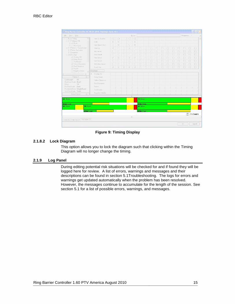
2.1.8 Timing Display
2.1.8.1 Timing Diagram
This diagram gives you the ability to view and modify sequence and timing plans through a graphical interface. The Timing Diagram will display the timing defined within the Pattern shown in the Pattern Globals Table. To display the Base Timing, Free Running timing, double click on the item Base Timing within the Tree View. The timing can be changed by dragging within this Timing Diagram. If a pattern is selected, the split values will be modified; if Free Running is selected, the Max times will be modified.
RBC Editor
Ring Barrier Controller 1.60 PTV America August 2010 15
Figure 9: Timing Display
2.1.8.2 Lock Diagram
This option allows you to lock the diagram such that clicking within the Timing Diagram will no longer change the timing.
2.1.9 Log Panel
During editing potential risk situations will be checked for and if found they will be logged here for review. A list of errors, warnings and messages and their descriptions can be found in section 5.1Troubleshooting. The logs for errors and warnings get updated automatically when the problem has been resolved. However, the messages continue to accumulate for the length of the session. See section 5.1 for a list of possible errors, warnings, and messages.

RBC Editor
16 Ring Barrier Controller 1.60 PTV America August 2010
Figure 10: Log Panel
2.1.9.1 Errors
This table lists situations that have been created that may cause VISSIM to crash or a simulation to not be able to run.
2.1.9.2 Warnings
This table lists situations that have been created that are invalid.
2.1.9.3 Messages
This table lists other logged messages regarding the current session.

Definitions
Ring Barrier Controller 1.60 PTV America August 2010 17
3 Definitions
3.1 Base Timing
3.1.1 Basic
3.1.1.1 SG Number
Signal Group numbers for corresponding signal group. The signal group number that will be created in VISSIM and will be used to create signal heads.
3.1.1.2 SG Name
The signal group name is currently only used within the RBC graphical interface.
3.1.1.3 Min Green
This parameter defines the minimum green time that the signal group will serve before changing to yellow. In the absence of any extension, the signal group will serve this minimum green time before it is eligible to terminate. This value is also used during offset seeking as a minimum value that the controller can display for the signal group. If this value is set artificially too high, the controller will take longer to get back into coordination and could possibly prevent the controller from getting back into coordination (if you set the min green equal to max green).
3.1.1.4 Veh Extension
The allowed time between successful vehicle extensions before a signal group will gap out. If the signal group Time To Reduce parameter is non-zero, this allowed gap between vehicles will be reduced according to volume/density timing defined for the signal group. Volume/density timing parameters are described in Base Timing, Advanced.
3.1.1.5 Max 1
This parameter defines the maximum time that the signal group will be allowed to extend before it will max-out. A max-out will make a signal group eligible to terminate, even though it may not have gapped-out. Normally, the maximum green timer will not begin counting until an opposing call to the signal group is present. An exception to this rule is when the signal group is a flagged as a Max Recall signal group, in which case the maximum green timer will begin counting as soon as the signal group changes to green. Max 1 is the default maximum green time for each signal group.
3.1.1.6 Yellow
The time a signal group will time a yellow interval before advancing to red. This time cannot be abbreviated by any operation.
3.1.1.7 Red Clearance
The time a signal group will time red before a conflicting signal group will be allowed to begin timing.
3.1.1.8 Ped SG Number
Signal Group numbers for the corresponding pedestrian signal group. The signal group number that will be created in VISSIM and will be used to create signal heads for the pedestrian movements.

Definitions
18 Ring Barrier Controller 1.60 PTV America August 2010
3.1.1.9 Walk
The minimum time a signal group will display a walk indication before advancing to the pedestrian clearance interval (flashing don’t walk). Pedestrian signal groups may rest in the walk interval following the minimum walk time if the Walk Rest option is flagged for the signal group. The minimum walk time can be shortened if the signal group is not permitted by an active Preempt. A signal group may not advance to yellow while the pedestrian movement is in the walk interval.
3.1.1.10 Ped Clear (FDW)
The time a signal group will display a flashing don’t walk indication before advancing to solid don’t walk. This time can be shortened or omitted if the signal group is not permitted by an active Preempt. A signal group may not advance to Yellow while the pedestrian movement is in the pedestrian clearance interval.
3.1.1.11 Start Up
Signal Groups that will be green at the start of the simulation. By default, these signal groups will begin timing in green with walk (if there is pedestrian timing defined). The controller will not start up conflicting signal groups if conflicting signal groups are defined in this parameter. If no signal groups are selected for Start Up, the first signal groups listed in the Sequence will start in green at the start of the simulation.
3.1.1.12 Min Recall
Signal groups flagged for this option will receive an automatic vehicle call when they are not green.
3.1.1.13 Max Recall
Signal groups flagged for this option will receive an automatic vehicle call and extension. The maximum green timer will unconditionally begin timing at the beginning of green. Normally, the maximum green timer will only time if there are opposing calls to the signal group.
3.1.1.14 Ped Recall
Signal groups flagged for this option will receive an automatic pedestrian call when they are not in walk.
3.1.1.15 Soft Recall
Signal groups flagged for this option will receive an automatic vehicle call when they are not green and there are no vehicle or pedestrian detectors activated.
3.1.1.16 NSE Max Recall
Signal groups flagged for this option will receive an automatic extension if they receive a vehicle call that starts the signal group timing.
3.1.1.17 Dual Entry
When one or more signal groups are chosen as Signal Group Next in a new concurrent barrier group, not all rings may have a compatible signal group with a call in that same concurrent barrier group. In such rings with no Signal Group Next, a compatible with the new concurrent barrier group may be automatically selected as Signal Group Next if the signal group is flagged as a Dual Entry signal group. This feature is often used for through movement signal groups such that if one signal group is called, the signal group in the opposite direction will automatically serve, even if it doesn’t have a call.
Definitions
Ring Barrier Controller 1.60 PTV America August 2010 19
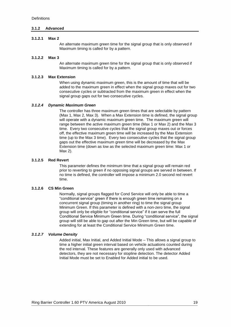
3.1.2 Advanced
3.1.2.1 Max 2
An alternate maximum green time for the signal group that is only observed if Maximum timing is called for by a pattern.
3.1.2.2 Max 3
An alternate maximum green time for the signal group that is only observed if Maximum timing is called for by a pattern.
3.1.2.3 Max Extension
When using dynamic maximum green, this is the amount of time that will be added to the maximum green in effect when the signal group maxes out for two consecutive cycles or subtracted from the maximum green in effect when the signal group gaps out for two consecutive cycles.
3.1.2.4 Dynamic Maximum Green
The controller has three maximum green times that are selectable by pattern (Max 1, Max 2, Max 3). When a Max Extension time is defined, the signal group will operate with a dynamic maximum green time. The maximum green will range between the active maximum green time (Max 1 or Max 2) and the Max 3 time. Every two consecutive cycles that the signal group maxes out or forces off, the effective maximum green time will be increased by the Max Extension time (up to the Max 3 time). Every two consecutive cycles that the signal group gaps out the effective maximum green time will be decreased by the Max Extension time (down as low as the selected maximum green time: Max 1 or Max 2).
3.1.2.5 Red Revert
This parameter defines the minimum time that a signal group will remain red prior to reverting to green if no opposing signal groups are served in between. If no time is defined, the controller will impose a minimum 2.0 second red revert time.
3.1.2.6 CS Min Green
Normally, signal groups flagged for Cond Service will only be able to time a “conditional service” green if there is enough green time remaining on a concurrent signal group (timing in another ring) to time the signal group Minimum Green. If this parameter is defined with a non-zero time, the signal group will only be eligible for “conditional service” if it can serve the full Conditional Service Minimum Green time. During “conditional service”, the signal group will still be able to gap out after the Min Green time, but will be capable of extending for at least the Conditional Service Minimum Green time.
3.1.2.7 Volume Density
Added initial, Max Initial, and Added Initial Mode – This allows a signal group to time a higher initial green interval based on vehicle actuations counted during the red interval. These features are generally only used with advanced detectors, they are not necessary for stopline detection. The detector Added Initial Mode must be set to Enabled for Added initial to be used.

Definitions
20 Ring Barrier Controller 1.60 PTV America August 2010
Figure 11: Added Initial Operation
3.1.2.8 Added initial
This parameter defines the amount of time that is added to the variable initial green interval per each vehicle actuation that is received during the yellow and red signal group intervals. Only vehicle actuations received on detectors enabled as “Added” detectors will add time to the variable initial green interval. Regardless of the number of vehicle actuations received, the maximum variable initial green will at most be the Max Initial time. The effective initial green time will be no lower than the Min Green time. The effective initial green time will be the greater of the Min Green time or the variable initial green time. The variable initial interval will begin timing concurrent with the minimum green interval and will only extend the initial green if it is greater than the minimum green time. The initial green interval can only be abbreviated if the signal group is not permitted by an active preempt.
3.1.2.9 Max Initial
This parameter defines the maximum time for the variable initial green interval.
Min Green + Max Initial
Min Green
SG Green
INITIAL
GREEN
SG Red
Effective Initial Green (once it exceeds Min Green)
Vehicle Actuations
Initial Green will not exceed
Min Green + Max Initial
Added Initial time (added to the initial green per actuation

Definitions
Ring Barrier Controller 1.60 PTV America August 2010 21
3.1.2.10 Gap Reduction
Min Gap, Reduce After and Time To Reduce – This allows a signal group extension time to decrease after the start of green.
Figure 12: Gap Reduction
3.1.2.11 Min Gap
Normally, the allowed gap between vehicles before a signal group gaps out is the Veh Extension. When using gap reduction, the allowed gap between vehicles is reduced from the Veh Extension down to the Minimum Gap time. Gap Reduction will be used to determine the variable gap in effect if the Time To Reduce is a non-zero value.
3.1.2.12 Reduce After
When using Gap Reduction, this is the time following the start of green on the signal group that must elapse before the gap in effect begins to be reduced. During this period, the gap in effect is the Veh Extension. Gap Reduction will be used to determine the variable gap in effect if the Time To Reduce is a non-zero value.
3.1.2.13 Time To Reduce
When using Gap Reduction, this is the time period over which the gap in effect is reduced from the Veh Extension down to the Minimum Gap. This Gap Reduction will not begin until the Reduce After time has elapsed since the start of green on the signal group. A non-zero Time To Reduce implies that gap reduction will be used to compute the variable gap in effect.
3.1.2.14 Delayed Walk
Normally, a signal group will change to green and walk simultaneously. With a non-zero Delayed Walk time, the signal group will change green this amount of time prior to the signal group changing to walk. This results in a green and don’t walk indication following the red interval until this Delayed Walk time has expired.
3.1.2.15 Walk Expand
Pedestrian signal group walk times will be expanded such that the pedestrian signal group will finish timing at the end of the signal group green. During Free operation, this time will be determined exclusively by the signal group Maximum time in effect. During coordination, this option will be the equivalent of flagging the Walk Rest option for the signal group.
Reduce After Vehicle Extension
Min Gap
SG Green
GAP IN EFFECT
SG Red
TIME
Time To Reduce

Definitions
22 Ring Barrier Controller 1.60 PTV America August 2010
3.1.2.16 Walk Rest
Pedestrian signal groups will normally advance to the pedestrian clearance interval following the end of the walk. For FREE operation, flagging a signal group as Walk Rest will allow the signal group to rest at the end of walk in the absence of opposing calls. During coordination, all signal groups flagged for this option will expand the signal group walk time such that the pedestrian signal group will finish timing at the end of the signal group green (determined by a combination of Maximum Green times and computed force-off points). During coordination, the WalkRestMode defined for the active coordination pattern will dictate whether or not the coordinated signal group pedestrian movements will automatically advance to pedestrian clearance each cycle or rest in walk in the absence of opposing calls.
3.1.2.17 Ped Recycle
Pedestrian signal groups flagged for this parameter that are in don’t walk will be allowed to begin late service (after the vehicle signal group has already changed green) if: 1) The intersection is Free and there is enough maximum green time remaining on the signal group to serve the full Walk, Ped Clear (FDW), and Solid Don’t Walk times. 2) The signal group is running as coordinated and there is both enough maximum green time and time until the signal group will be forced off to serve the full Walk, Pedestrian Clearance, and Solid Don’t Walk times.
3.1.2.18 Ped Scramble
Pedestrian signal groups flagged with this option will allow service to ALL pedestrian movements that are not flagged as omitted (vehicle movements other than those signal groups timing will remain red). Walk, Ped Clear (FDW), and solid don’t walk intervals will be timed according to timing programmed for each pedestrian signal group. Any pedestrian indication that is showing a walk indication just before a pedestrian scramble is next will remain in walk. When the pedestrian scramble is timing and a pedestrian movement with a walk indication is also the next signal group following the scramble, then that pedestrian indication will remain in walk. All other pedestrian movements must complete timing prior to the termination of the pedestrian scramble.
3.1.2.19 Yellow Lock
For any signal group flagged with this option, calls that are received while the signal group is yellow or red will be locked until the signal group is served.
3.1.2.20 Red Lock
For any signal group flagged with this option, calls that are received while the signal group is red will be locked until the signal group is served.
3.1.2.21 No Term Call
Normally, a locked call is placed on any signal group that is still extending when it terminates. Any signal group flagged for this option will not have a locked call placed upon termination.
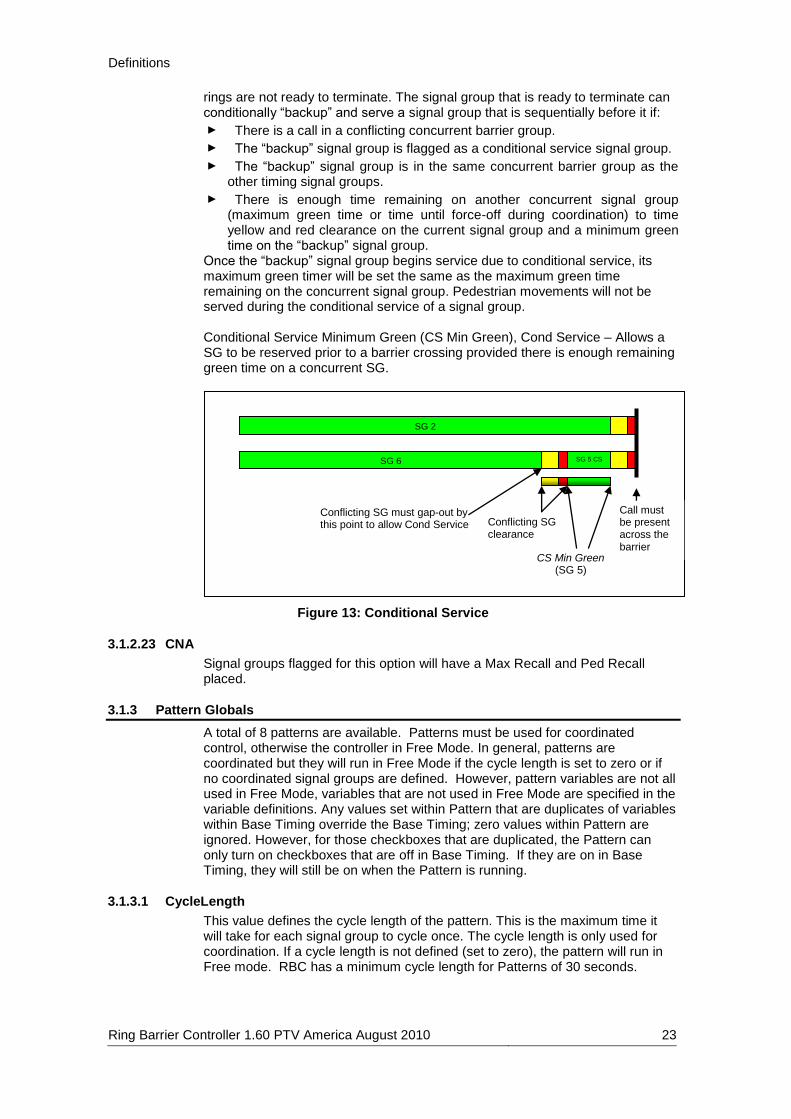
3.1.2.22 Cond Service
When signal groups are timing such that the next signal groups to serve require a barrier crossing, all signal groups timing must be ready to terminate before the signal groups across the barrier are served. Often, one signal group is ready to terminate in one ring but can’t because one or more signal groups in the other
Definitions
Ring Barrier Controller 1.60 PTV America August 2010 23
rings are not ready to terminate. The signal group that is ready to terminate can conditionally “backup” and serve a signal group that is sequentially before it if:
► There is a call in a conflicting concurrent barrier group.
► The “backup” signal group is flagged as a conditional service signal group.
► The “backup” signal group is in the same concurrent barrier group as the other timing signal groups.
► There is enough time remaining on another concurrent signal group (maximum green time or time until force-off during coordination) to time yellow and red clearance on the current signal group and a minimum green time on the “backup” signal group.
Once the “backup” signal group begins service due to conditional service, its maximum green timer will be set the same as the maximum green time remaining on the concurrent signal group. Pedestrian movements will not be served during the conditional service of a signal group. Conditional Service Minimum Green (CS Min Green), Cond Service – Allows a SG to be reserved prior to a barrier crossing provided there is enough remaining green time on a concurrent SG.
Figure 13: Conditional Service
3.1.2.23 CNA
Signal groups flagged for this option will have a Max Recall and Ped Recall placed.
3.1.3 Pattern Globals
A total of 8 patterns are available. Patterns must be used for coordinated control, otherwise the controller in Free Mode. In general, patterns are coordinated but they will run in Free Mode if the cycle length is set to zero or if no coordinated signal groups are defined. However, pattern variables are not all used in Free Mode, variables that are not used in Free Mode are specified in the variable definitions. Any values set within Pattern that are duplicates of variables within Base Timing override the Base Timing; zero values within Pattern are ignored. However, for those checkboxes that are duplicated, the Pattern can only turn on checkboxes that are off in Base Timing. If they are on in Base Timing, they will still be on when the Pattern is running.
3.1.3.1 CycleLength
This value defines the cycle length of the pattern. This is the maximum time it will take for each signal group to cycle once. The cycle length is only used for coordination. If a cycle length is not defined (set to zero), the pattern will run in Free mode. RBC has a minimum cycle length for Patterns of 30 seconds.
Conflicting SG must gap-out by this point to allow Cond Service Conflicting SG
clearance
SG 6
SG 2
SG 5 CS
CS Min Green (SG 5)
Call must be present across the barrier

Definitions
24 Ring Barrier Controller 1.60 PTV America August 2010
3.1.3.2 Offset
When coordinated, the local cycle timer will be offset from the master cycle timer by the defined offset time.
3.1.3.3 MaxGreenMode
This setting determines the maximum green mode that will be used for all signal groups while the coordination pattern is active. This selection is only valid for coordinated patterns; if used for free running patterns the value will be ignored. The selections are:
► MaxInhibit – All signal groups will ignore their maximum green timers. Signal groups will only terminate if they gap-out or reach their force-off point.
► Max1 – All signal groups will observe their Max 1 setting.
► Max2 – All signal groups will observe their Max 2 setting.
► Max3 – All signal groups will observe their Max 3 setting.
3.1.3.4 PermissiveMode
This setting defines the permissive mode for the coordination pattern. The permissive mode controls the method in which permissive periods are opened and closed for all non-coordinated signal groups. The controller will only yield to signal groups that are permissive following the end of green on each coordinated signal group. The permissive modes are as follows:
► SingleBand – The permissive period for non-coordinated signal groups will open:
At the beginning of the coordinated signal group green for signal groups in the same ring and concurrent barrier group as the coordinated signal group, or
At the beginning of the lagging coordinated signal group green for signal groups outside of the same concurrent barrier group as the coordinated signal groups.
The permissive period for non-coordinated signal groups will close:
When there is no longer enough time to clear all timing signal groups and serve the longer of the Minimum Green or Permissive Green on the signal group, or
When the signal group is in a different concurrent barrier group then the coordinated signal groups and any coordinated signal group has yielded to a signal group that is sequentially before the coordinated signal group, in the same ring and concurrent barrier group (i.e. a lagging coordinated signal group yielding to its opposing left turn will close all cross street permissive periods for the remainder of the cycle).
► MultiBand – The permissive period for non-coordinated signal groups will open:
The same as Single Band Permissive operation above, but only for the first signal group in each ring that sequentially follows the coordinated signal group.
For each subsequent signal group, the permissive period will open once the previous signal group’s permissive period closes (Only one signal group per ring can be permissive at any given time).
The permissive period for non-coordinated signal groups will close the same as they do for Single Band Permissive operation above.
► Reservice – The permissive mode will operate the same as Single Band Permissives until the Coordinated signal groups yield to a non-coordinated movement. ALL signal groups will be allowed to reserve. After the coordinated signal groups yield once:

Definitions
Ring Barrier Controller 1.60 PTV America August 2010 25
Signal Groups in the non-coordinated barrier group will be allowed to reserve if there is enough time to serve the minimum green time (or minimum permissive green time if greater than minimum green time) and still be able to have the leading coordinated signal group green by the start of its split.
Signal Groups in the coordinated barrier group will be allowed to reserve if there is enough time to serve the minimum green time (or minimum permissive green time if greater than minimum green time) and still be able to have the coordinated signal group in the same ring green by the start of its split.
Figure 14: Coordination Permissive Modes
3.1.3.5 PedPermMode
This setting defines the pedestrian permissive mode for the coordination pattern. This mode determines how pedestrian calls will be served based on the computed pedestrian permissive period. The pedestrian permissive modes are as follows:
► Yield – Once the pedestrian permissive has closed, a pedestrian call will be omitted until the next cycle. However, if a vehicle call is placed while the vehicle permissive is still open but the pedestrian permissive has closed, pedestrian calls WILL be served once the signal group turns green. In this case, there will not be enough time to serve the pedestrian movement without possibly going into transition.
1/5 perm band
4/8 perm band
(Nominal Cycle) Time
SG 2/6 SG 4/8 SG 1/5
SG 2/6 SG 4/8 SG 1/5
Conflicting SG clearance
***Minimum permissive green
1/5 perm band 4/8 perm band
SG 2/6 SG 4/8 SG 1/5
*** Minimum permissive green = SG minimum green unless a higher value is specified under coordination pattern
Single Band / Reservice Permissive Modes (permissive bands open up simultaneously)
Multi Band Permissive Mode (permissive bands open up sequentially)

Definitions
26 Ring Barrier Controller 1.60 PTV America August 2010
► Partial – Once the pedestrian permissive has closed, a pedestrian call will be omitted until the next cycle. If a vehicle call is placed while the vehicle permissive is still open but the pedestrian permissive has closed, pedestrian calls WILL NOT be served once the signal group turns green.
► Omit – Once the pedestrian permissive has closed, a pedestrian call will be omitted until the next cycle. If a vehicle call is placed while the vehicle permissive is still open but the pedestrian permissive has closed, pedestrian calls WILL NOT be served once the signal group turns green. This is the default setting.
Figure 15: Coordination Pedestrian Permissive Modes
3.1.3.6 WalkRestMode
This setting defines the walk rest mode of the coordinated signal groups when the coordination pattern is active. The selections are:
End veh permissive (EVP) End ped permissive
(EPP)
Veh served (ped omitted)
(Nominal Cycle) Time
SG 2/6 SG 4/8
Conflicting SG clearance ***Minimum
permissive green
SG 2/6 SG 4/8
EPP EVP
SG 2/6 SG 4/8
EPP EVP
SG 2/6
EPP EVP
Late ped call (omitted)
Veh call accepted
Veh & ped call served (SG violates force-off)
SG 2/6 SG 4/8
EPP EVP
Minimum walk+pedclr
Yield Ped Permissive Mode
Partial Ped Permissive Mode (V=P Perm flagged)
Partial Ped Permissive Mode (V=P Perm flagged)
Omit Ped Permissive Mode
Veh call accepted
Late ped call (during clearance)
Veh served (ped omitted)
Late ped call (omitted) Veh call omitted due to omitted ped call
Late ped call (omitted)
Veh call accepted
Definitions
Ring Barrier Controller 1.60 PTV America August 2010 27
► Yield – The coordinated signal groups flagged for Walk Rest operation will always terminate their pedestrian indications so the pedestrian timing is finished by the force-off point. This way, the coordinated signal groups will always be ready to terminate at the force-off point due to an opposing permissive call. If all permissive periods close and the coordinated signal groups have not yielded to an opposing signal group, the coordinated pedestrian signal group can recycle to walk.
► Opposing Call – The coordinated signal group pedestrian movements will terminate only if there is an opposing call to a signal group that has an open permissive period. When this mode is selected, permissive periods for all signal groups will close earlier if the pedestrian movement of a coordinated signal group must first be terminated before the signal group can be served.
3.1.3.7 ExplicitForceOffs
During an active coordination pattern, activates explicit Force Offs defined in the pattern instead of using Splits.
3.1.3.8 ExplicitPermissives
During an active coordination pattern using explicit Force Offs defined in the pattern, activates explicit Permissive Periods defined in the pattern instead of using automatically defined Permissive Periods. These can only be used with explicit Force Offs.
3.1.3.9 AltPattern1
During an active coordination pattern, it is possible to activate one of two alternate patterns based on an active Queue detector (i.e. activate an alternate pattern due to congestion detected by a queue detector). Once a queue detector with a Control of AltPat1 has detected a queue, the corresponding AltPattern1 will be selected in place of the current commanded pattern.
3.1.3.10 AltPattern2
During an active coordination pattern, it is possible to activate one of two alternate patterns based on an active queue detector (i.e. activate an alternate pattern due to congestion detected by a Queue detector). Once a queue detector with a Control of AltPat2 has detected a queue, the corresponding AltPattern2 will be selected in place of the current commanded pattern.
3.1.4 Pattern / Coordination
3.1.4.1 Split
The amount of time allocated in the cycle for each signal group to time. The split includes the time it will take the green, yellow, and red intervals to time for each signal group. The split should at least accommodate the signal group Min Green plus Yellow Clearance plus Red Clear time, but it doesn’t necessarily need to accommodate the full pedestrian service time for an actuated pedestrian signal group. The sum of the splits of all signal groups in each ring should add up to the CycleLength. Please take into account that in concurrent barrier groups that have one or more rings without any signal groups, the controller will automatically insert split time into the rings without any signal groups so that the split sums will be aligned at each barrier.
3.1.4.2 Split Extension
Normally, a coordinated signal group will be held green until its force-off point. By programming a non-zero value into this parameter for coordinated signal groups, the signal group will be allowed to gap-out this amount of time earlier

Definitions
28 Ring Barrier Controller 1.60 PTV America August 2010
than its force-off point, if there is nothing extending the signal group. For example, a value of 5 for a coordinated signal group will allow the coordinated signal group to terminate 5 seconds earlier than its force-off if there are no vehicles extending the signal group. For non-coordinated signal groups, programming a non-zero value for this parameter will force-off the signal group this amount of time earlier than the normal force-off would be. This may be used when the full pedestrian timing will utilize the full split, but it is desired that when the vehicle movement times alone, it will finish earlier (by the time defined in this parameter) than the full Split. For example, if the full split is 30 seconds, the signal group clearance (yellow plus red) is 5 seconds, the pedestrian timing (Walk plus Ped Clear (FDW)) is 25 seconds, this implies a green time of 25 seconds (30 second split minus 5 second clearance). If it is desired that the vehicle movement alone (without the pedestrian movement) only times 20 seconds of green, program the Extended Split time to 5 seconds.
3.1.4.3 Floating Green
For signal groups flagged as Floating Force Off Signal groups, this is the amount of time beyond the computed signal group green time (Split minus Yellow and Red Clear) that a Floating Force Off signal group will be allowed to time before being forced off. Regardless of the value of this parameter, the signal group will be forced off by its computed signal group force-off point, even if it hasn’t finished timing its computed green time.
3.1.4.4 Perm Min Green
When the controller computes the permissive period for each signal group, the default operation is to close the permissive period as soon as the signal group will not be able to time its Minimum Green prior to its force-off point. Programming a non-zero value for this parameter will modify the permissive period so that it will close when the signal group can’t time the Permissive Green time prior to its force-off point. If the Permissive Green is less than the Minimum Green time for a signal group, this parameter will be ignored.
3.1.4.5 Min Green
This parameter defines the minimum green time that a signal group will serve before changing to yellow. In the absence of any extension, the signal group will serve this minimum green time before it is eligible to terminate. This pattern min green value will over ride values in the Basic timing when the pattern is running. If the value is set to zero within the pattern the controller will use the Min Green set in the Basic timing.
3.1.4.6 Alternate Max
When defined for a signal group, this value over rides all max green times defined for this signal group when this pattern is running. This new max green time is used for both coordinated and free running patterns.
3.1.4.7 Veh Extension
The allowed time between successful vehicle extensions before a signal group will gap out. If the signal group Time To Reduce parameter is non-zero, this allowed gap between vehicles will be reduced according to Volume Density timing defined for the signal group. Volume Density timing parameters are described in Base Timing, Advanced.
3.1.4.8 Transition Min
This is the shortest that the signal group Split will be reduced to when the controller is running short-way transition. Regardless of the value of this

Definitions
Ring Barrier Controller 1.60 PTV America August 2010 29
parameter, the split will never be reduced shorter than the sum of the signal group Min Green plus Yellow Clearance plus Red Clear.
3.1.4.9 Transition Max
This is the longest that a signal group Split will be inflated to when the controller is running long-way transition. This value should be at least as long as the nominal Split time for each signal group. These values will automatically be set to split plus 20% and will be adjusted every time the split value changes. If you wish to set these to some other value, you must do so after the split is entered otherwise your value will be overwritten.
3.1.4.10 Force Off
Defines the time in seconds measured past local zero point that selected green phase will end within local cycle. This value is only used if ExplicitForceOffs is set to On, otherwise automatic force offs are used as defined by Split and OffsetReference.
3.1.4.11 Permissive Period
Defined by Permissive Start and Permissive End, this is the time period within the cycle in which a call for the signal group can result in green time for that signal group if the call remains after prior signal groups with calls have cleared.
3.1.4.12 Permissive Start
The time in seconds measured from the local zero point (defined by the Force Offs) at which a call for the signal group will be acknowledged by the controller and will cause the coordinated signal group to go to clearance if running. This value is only used if both ExplicitForceOffs and ExplicitPermissives are set to On, otherwise automatic permissive periods are used as defined by PermissiveMode.
3.1.4.13 Permissive End
The time in seconds measured from the local zero point (defined by the Force Offs) at which a call for the signal group will no longer be acknowledged by the controller. This value is only used if both ExplicitForceOffs and ExplicitPermissives are set to On, otherwise automatic permissive periods are used as defined by PermissiveMode.
3.1.4.14 Max 2
Signal groups that will observe Max 2 timing while the pattern is active. This setting is also used in Free Mode.
3.1.4.15 Max 3
Signal groups that will observe Max 3 timing while the pattern is active. If both Max 2 and Max 3 are selected for a signal group, Max 3 will be used. This setting is also used in Free Mode.
3.1.4.16 Floating Force Off
Normally, a signal group that gaps-out early will leave extra split time available for all upcoming signal groups to utilize. Any signal group that is flagged for this parameter will be forced-off once the signal group serves its computed green time (split time minus yellow and red clearance). The signal group can remain green beyond its computed green time by the amount of time defined in the Floating Green parameter. Regardless of the defined Floating Green time, the signal group will still be forced off by its computed force-off point, even if the signal group has not finished serving its computed green time.

Definitions
30 Ring Barrier Controller 1.60 PTV America August 2010
3.1.4.17 Coordinated
There must be a coordinated signal group in each ring of any ring group that will be coordinated. All coordinated signal groups must be in the same concurrent barrier group. Coordinated signal groups are automatically called, and are usually held in green until their force-off point (also known as the yield point). Coordinated signal groups are typically the main street through signal groups of a street where vehicular progression is desired. If you do not define any coordinated signal groups the controller will run in Free Mode.
3.1.4.18 Walk Rest
Any signal group that is flagged as a Walk Rest signal group will expand its walk time so that the pedestrian timing will finish at the signal group force-off point. Signal groups flagged as Walk Rest or Walk Expand under Free operation will also operate as if they are flagged for this parameter.
3.1.4.19 Ped Recall
When the coordination pattern is active, signal groups flagged for this option will receive an automatic pedestrian call when they are not in walk. This value will also be used if the pattern is run in free mode.
3.1.4.20 Min Recall
When the coordination pattern is active, signal groups flagged for this option will receive an automatic vehicle call when they are not green. This value will also be used if the pattern is run in free mode.
3.1.4.21 Max Recall
When the coordination pattern is active, signal groups flagged for this option will receive an automatic vehicle call and extension. The maximum green timer will unconditionally begin timing at the beginning of green. Normally, the maximum green timer will only time if there are opposing calls to the signal group. This value will also be used if the pattern is run in free mode.
3.1.4.22 NSE Max Recall
Signal groups flagged for this option will run to at least their max green time if they receive a vehicle call. This value will also be used if the pattern is run in free mode.
3.1.4.23 Veh Omit
Signal groups flagged with this option will not be served. Preemption can override a vehicle signal group omit. This value will also be used if the pattern is run in free mode.
3.1.4.24 Ped Omit
Pedestrian signal groups flagged with this option will not be served. Preemption can override a pedestrian signal group omit. This value will also be used if the pattern is run in free mode.
3.1.4.25 Max Inhibit
When the pattern MaxGreenMode is set to anything except for Maximum Green Inhibit, this parameter allows individual signal groups to be defined for Maximum Green Inhibit (i.e. ignore the signal group maximum green timer and only terminate by gap-out or force-off). Note that programming the Maximum Green Mode to Maximum Green Inhibit will place ALL signal groups on Maximum Green Inhibit.
Definitions
Ring Barrier Controller 1.60 PTV America August 2010 31
3.1.4.26 Lead
Allows the user to change the sequence when a pattern is running; the timing diagram will show the new sequence. If the sequence does not change for this pattern, this parameter does not need to be set. Pattern 8 uses an Alternate Sequence instead of Lead.
3.1.4.27 CNA
Signal groups flagged for this option will have a Max Recall and Ped Recall placed.
3.1.4.28 Veh=Ped Permissive
Normally, permissive periods for vehicle and pedestrian movements are computed separately based on the respective vehicle and pedestrian minimum timing. Typically, pedestrian movements require more time than the minimum green for the corresponding vehicle movement. By flagging this parameter for a signal group, its vehicle permissive will close once the pedestrian permissive closes (i.e. once there is not enough time to serve the pedestrian movement, the corresponding vehicle movement will also be omitted from service for that cycle).
3.1.4.29 Alternate Sequence
Allows the user to change the sequence when a pattern is running; the timing diagram will show the new sequence. If the sequence does not change for this pattern, this parameter does not need to be set. This feature replaces the Lead values for Pattern 8 and is only available for Pattern 8. This allows sequence changes that are not possible using Lead when more than two signal groups are within one ring barrier group.
3.1.5 Pattern Schedule
3.1.5.1 Pattern Number
This is the pattern that will run starting at the defined Pattern Start Time. The Free option will run the Basic and Advanced timing.
3.1.5.2 Pattern Start Time
This is the simulation start time, in seconds, at which the defined Pattern will start running. If more than one pattern is defined for the same start time, the last listed will be the pattern that is run for that time. Active patterns will only end with another pattern begins.

Definitions
32 Ring Barrier Controller 1.60 PTV America August 2010
3.1.6 Sequence
Clicking on the column header will create a barrier to the right of the column below. Only signal group numbers that have been defined can be used in the Sequence. A signal group can only be placed once in the sequence. A Signal Group must be included in the Sequence for the signal group to time, otherwise the timing information will be ignored. A maximum of 8 barriers and 4 rings are available.
Figure 16: Sequence Editor
3.1.7 Conflict SGs
Normally, within the same concurrent barrier group, all signal groups in a ring are compatible with all signal groups in other concurrent rings. Occasionally, there are intersections that have additional conflicts between two signal groups that are in different rings, but still within the same concurrent barrier group (i.e. two opposing left turn signal groups with a limited turning radius). Such conflicts should be flagged in the Conflicting Signal Group feature.
3.1.8 Overlaps
3.1.8.1 Overlap SG
Signal Group numbers for corresponding overlap. The signal group number that will be created in VISSIM and will be used to create signal heads that used the timing defined for this overlap.
3.1.8.2 Delay Green
When a Parent signal group is flagged as a Delay Enable Signal Group is timing, the overlap will time this delay prior to changing from red to green.
3.1.8.3 Trail Green
When a Parent signal group flagged as a Trail Enable Signal Group is timing, the overlap will time this green clearance (trailing green time) prior to changing yellow.

Definitions
Ring Barrier Controller 1.60 PTV America August 2010 33
3.1.8.4 Yellow Clearance
The time an overlap will time a yellow indication before advancing to red. This time can not be abbreviated by any operation.
3.1.8.5 Red Clearance
The time an overlap will display red before any signal groups that conflict with either the overlap or its Parent signal groups can begin timing. This time can not be abbreviated by any operation.
3.1.8.6 Parent
These are the signal groups that the overlap will be allowed to time with. When one parent signal group is timing and another parent signal group is next, the overlap will remain green (unless a negative vehicle or pedestrian signal group is next). When the last parent signal group terminates, the overlap will also terminate.
3.1.8.7 Negative Green
These are the Parent signal groups that the overlap will be allowed to time with except when the signal group is green (i.e. the overlap will still be able to time when the signal group is in a yellow or red clearance interval). When Negative Green Signal groups are defined, there are two possible ways for the overlap to terminate when a Negative Green Signal group is next. If the Negative Green Signal group is also flagged as a Parent Signal Group, then the overlap will time a yellow and red clearance interval before the Negative Green Signal group will begin timing. If the Negative Green Signal group is not flagged as a Parent Signal group, then the overlap will remain green until the Parent signal group begins timing, at which point it will advance directly to red without any yellow or red clearance (commonly used in California and Illinois 5-section right turn head controls). Negative Green SGs will affect the overlap operation differently dependent upon how they are combined with Parent SGs.
Figure 17: Overlap Negative Green Operation (Right Turn Head Control)
3.1.8.8 Delay Enable
An optional delay (Delay Green time) will be timed prior to the overlap changing from red to green if any signal group flagged for this option is timing.
SG 2 SG 3 SG 2
Parents = SG 2 + 3, Negative Green = SG 2
SG 2
Overlap
SG 3 SG 2
Parents = SG 3, Negative Green = SG 2
Overlap
Definitions
34 Ring Barrier Controller 1.60 PTV America August 2010
3.1.8.9 Trail Enable
Normally when an overlap terminates, it will begin timing its yellow clearance interval. An optional green clearance interval (Trail Green time) will be timed prior to the yellow clearance interval if any signal group flagged for this option is timing. This is commonly used at intersections where an overlap controls a movement that cascades one or more signal groups and requires addition travel time from the movements controlled by the Parent signal groups.
3.1.8.10 Negative Vehicle
These are signal groups that are not allowed to time with the overlap. The overlap will terminate and complete its red clearance interval before any Negative Vehicle Signal group will time. If a Negative Vehicle Signal group is next, the overlap will terminate even if there is a Parent signal group that is currently timing or is next.
3.1.8.11 Negative Overlap
These are overlap signal groups that are not allowed to time with the overlap. If any of the overlaps flagged for this option are green or timing a yellow or red clearance, the current overlap will be held red until all such overlaps are finished timing. If two or more overlaps are truly conflicting to each other, the conflicts must be programmed in ALL overlaps. This parameter can be used to establish partial conflicting overlaps (i.e. Overlap 1 is NOT allowed to begin while Overlap 2 is timing, but Overlap 2 IS allowed to begin timing while Overlap 1 is timing).
3.1.9 Global Values
These parameters are defined only once per signal controller and therefore are used for all patterns within the signal controller. These parameters only apply when coordination is used.
3.1.9.1 OffsetReference
This is the point in the cycle where the master cycle timer will be equal to the defined Offset time when the controller is coordinated and not in transition (offset seeking). The selections are:
► LagFO (Lagging Force-Off) – The reference point will be at the force-off point for the lagging coordinated signal group.
► LeadGreen (Leading Start of Green) – The reference point will be at the start of the leading coordinated signal group green (the computed start of green, note that the signal group may actually return to green early if there is lack of demand on opposing movements).
► LagEnd (End of Lagging Red) – The reference point will be at the end of Red Clear for the lagging coordinated signal group.
► CoordEnd (End of Coordinated Group Red) – The reference point will be at the end of red for the last signal group in the concurrent barrier group with the coordinated signal groups.

Definitions
Ring Barrier Controller 1.60 PTV America August 2010 35
Figure 18: Coordination Offset Reference Modes
3.1.9.2 TransitionMode
This is the mode that all coordination patterns will use to transition when the local dial does not have the correct Offset to the master clock, VISSIM. The max transition values are automatically set to the split value plus 20%, and will be adjusted whenever a split value is changed. The selections are:
► Best – The controller will determine whether implementing one or more shorter cycles, or one or more longer cycles will achieve coordination the quickest. Min Green and pedestrian signal group timing restrict how short a transition cycle can be.
► LongMode – The controller will implement one or more longer cycles in order to achieve coordination.
► BestIgnorePed – Same as Best Way above, except when determining how short a transition cycle can be, the controller will ignore minimum pedestrian signal group timing for all actuated pedestrian movements (Note, this may allow for a cycle length that is shorter than needed if the actuated pedestrian movements are called which will in turn require subsequent transition cycles).
► Best2 – Same as the Best Way mode above with the exception of how the transition point is decided. Under any other transition mode, the local dial will halt whenever a coordinated signal group is not green at the beginning of its computed split. With the Best2 mode, the local dial will continue to run as long as the all coordinated signal groups will be able to time the larger of their Min Green or Perm Min Green times. This results in extra slack in the cycle that will prevent unnecessary transition.
3.2 Detectors
3.2.1 Vehicle
3.2.1.1 Detector Number
The detector number that should be used within VISSIM to Call or Extend the vehicle signal groups selected. There are 32 available vehicle detectors.
Leading/Lagging Left Turns
SG 2 (Coord SG) SG 4
LeadGreen
SG 1
SG 6 (Coord SG) SG 5 SG 8
SG 2 (Coord SG) SG 4 SG 1
SG 6 (Coord SG) SG 5 SG 8
Ring 1
Ring 2
Ring 1
Ring 2
Dual Lagging Left Turns
Lag coord SG end LagEnd,
Coord group end CoordEnd LagFO
Leading coord SG LeadGreen
Lag coord SG FO LagFO
Lag coord SG end LagEnd
Coord group end CoordEnd
Definitions
36 Ring Barrier Controller 1.60 PTV America August 2010
3.2.1.2 Delay
The amount of time a detector input must have continuous presence before placing a call to the Call signal groups.
3.2.1.3 Extend
The amount of time that Extend SGs will be extended after the detector input is off. See Detector Mode for alternate uses of the Extend time for different modes.
3.2.1.4 Carry Over
When the Detector Mode is Disconnect, this is the amount of time allowed between vehicle actuations during the Extend signal group green interval before the detector will be disconnected for the remainder of the green interval and cease to extend the signal group.
3.2.1.5 Queue Limit
When the Detector Mode is Disconnect, this is the amount of time after the start of the Extend signal group green interval when the detector will be disconnected for the remainder of the green interval, ceasing to extend the signal group.
3.2.1.6 Detector Mode
Determines the mode of the detector:
► No Disconnect – The detector will unconditionally Extend all defined Extend SGs for the signal group Veh Extension time.
► Disconnect – The detector will Extend any Extend SGs that are green until either:
The defined Queue Limit is a non-zero value and the Queue Limit has elapsed since the start of green on the current Extend Signal group or,
The defined Carry Over time has elapsed since the last vehicle actuation. Once the detector ceases to extend any green Extend SGs (a.k.a. has been virtually disconnected from the controller), it will remain disconnected for the remainder of the green interval on the current Extend Signal group. Signal groups will be extended by the signal group Veh Extension time.
► Disconnect 2 – The detector will extend any Extend Signal group that is green until either:
The defined Queue Limit is a non-zero value and the Queue Limit has elapsed since the start of green on the current Extend Signal group or,
The defined Carry Over time has elapsed since the last vehicle actuation. Once the detector ceases to extend any green Extend SGs (a.k.a. has been virtually disconnected from the controller), it will remain disconnected for the remainder of the green interval on the current Extend Signal group. By default, Extend SGs will be extended by the detector Carry Over time in place of the signal group Vehicle Extension time. If the detector Extend time is defined, Extend SGs will be extended by the detector Extend time in place of the signal group Veh Extension time.
► XSwitchExt – If any signal groups are green and are flagged for this parameter, those signal groups (XSwitch SGs) will be extended and the Call signal groups will not be called. The XSwitch SGs will be extended by the detector Extend time and not the signal group Veh Extension time.
3.2.1.7 Added Initial Mode
If Enabled, this detector will count the number of actuations received when ALL Call signal groups are yellow or red. When the next Call signal group changes to green, a variable initial interval will time based on the total number of actuations
Definitions
Ring Barrier Controller 1.60 PTV America August 2010 37
on all detectors enabled for the Added Initial Mode and the Added initial time defined for the signal group. The actuation count will then be reset to zero.
3.2.1.8 Call
Signal Groups that are called when the detector input is on.
3.2.1.9 Yellow Lock
Normally, detector signal group calls are only placed when the detector input is on. For any signal groups flagged for this parameter, calls placed by the detector during yellow will be locked until the signal group is served. Additional calls received while any Yellow Lock Signal group is green or next will not be locked. This is needed if no stop line detectors are present and only approach detectors are used. This may be inefficient if vehicle sneaks through on yellow or if right turns on red are permitted
3.2.1.10 Red Lock
For any signal groups flagged for this parameter, calls placed by the detector when the signal group is red will be locked until the signal group is served. Additional calls received while any Red Lock Signal group is green or next will not be locked. This may be inefficient if right turns on red are permitted, Red Lock locks call even after presence is lost, remembers call
3.2.1.11 Extend SGs
Signal Groups that are extended when the detector input is on. See Detector Mode, Carry Over, and Queue Limit for other extension operation parameters.
3.2.1.12 XSwitch SGs
If any signal groups are green and are flagged for this parameter, those signal groups (XSwitch SGs) will be extended and the Call signal groups will not be called. When the Detector Mode is set to XSwitchExt, cross switch signal groups will be extended by the detector Extend time. All other Detector Modes will extend the cross switch signal groups by the signal group Veh Extension time.
3.2.2 Pedestrian
3.2.2.1 Detector Number
The detector number that should be used within VISSIM to call the pedestrian signal groups selected. There are 16 available pedestrian detectors.
3.2.2.2 Call Peds
This parameter defines the pedestrian signal groups that are called when the detector input is on.
3.2.3 Queue
The 16 queue detectors are designed to detect vehicle queues that will impede traffic flow if not cleared. Each queue detector is linked to a vehicle detector. A queue detector must sense a programmable duration of constant presence before activating. Once the queue detector has activated, it must sense a programmable duration of no presence before it deactivates. Once a queue detector is activated it can alter the controllers pattern mode, initiate a preempt, alter signal group max times, or adjust transit priority operation.
3.2.3.1 Veh. Detector Number
This defines the vehicle detector number that will be used to detect vehicle presence for this queue detector. Once this vehicle detector has constant

Definitions
38 Ring Barrier Controller 1.60 PTV America August 2010
presence for the Delay On time period, the queue detector will be activated. A value of zero disables this queue detector.
3.2.3.2 Delay On
The Vehicle Detector Number must sense a constant presence for this time period before the queue detector is activated.
3.2.3.3 Delay Off
Once activated, the Vehicle Detector Number must sense a continuous lack of presence for this time period before the queue detector is deactivated.
3.2.3.4 Control
Once the queue detector has activated, it will modify the control mode according to the value of this parameter:
► None – The control mode will not be modified.
► Free – The controller will run Free.
3.2.3.5 Alt Pattern 1 – If the controller is running an active coordination pattern, the controller will run the ExplicitForceOffs
During an active coordination pattern, activates explicit Force Offs defined in the pattern instead of using Splits.
3.2.3.6 ExplicitPermissives
During an active coordination pattern using explicit Force Offs defined in the pattern, activates explicit Permissive Periods defined in the pattern instead of using automatically defined Permissive Periods. These can only be used with explicit Force Offs.
► AltPattern1 programmed for the active pattern.
► Alt Pattern 2 – If the controller is running an active coordination pattern, the controller will run the AltPattern2 programmed for the active pattern.
3.2.3.7 Action
Once the queue detector has activated, the controller will take the following action based on the value of this parameter:
► None – No action will be taken.
► Max2 – The controller will enable the Max 2 timing for the signal group programmed in the Action Index parameter.
► Max3 – The controller will enable the Max 3 timing for the signal group programmed in the Action Index parameter.
► Preempt – The controller will place a preempt call for the preempt number programmed in the Action Index parameter.
► Priority SG – During a transit priority request, the controller will modify the following operations of the signal group number programmed in the Action Index parameter:
The signal group will not be omitted due to the transit priority request.
The signal group green time will not be abbreviated due to the transit priority request.
3.2.3.8 Action Index
This defines the signal group number, preempt number, or transit priority SG number for the selected queue detector action. See Action above for a description of the index values.

Definitions
Ring Barrier Controller 1.60 PTV America August 2010 39
3.3 SC Communication
SC communication allows interaction between two or more signal controllers. The communication is defined within VISSIM and this table allows you to specify how the information will be used in this controller or what values will be sent from this controller.
3.3.1 SC Communication
3.3.1.1 SC Comm Numbers
The index number for the SC communication. There are 16 available communications.
3.3.1.2 Channel Number
This defines SC channel. This channel must also be defined within VISSIM and simply references the channel defined in the SC Communication within VISSIM.
3.3.1.3 Connect To
This defines where the information from the channel will be used.
► None – No action will be taken.
► Preempt detector – The controller will send or receive calls, based on the In/Out value, to/from the channel for the Preempt detector programmed in the Index parameter.
► SG Status – The controller will send or receive the status, based on the In/Out value, to/from the channel of the selected SG Number defined in the Index parameter. Output values are as follows: 1 for green, 2 for amber, 3 for red, and zero for anything else.
3.3.1.4 In/Out
This value defines whether the Channel will be used for sending or receiving.
► None – No action will be taken.
► In – The controller will receive values from the channel for the signal group programmed in the Index parameter.
► Out – The controller will send values from the channel for the signal group programmed in the Index parameter.
3.3.1.5 Index
This defines the number for the selected Connect To option. For Preempt detector, this defines which Preempt detector will be accessed by the channel. For SG Status, this defines which signal group will be accessed by the channel.
3.4 Preempt
Please note that this is a licensed feature and is not available with all VISSIM license levels. Normal preempts are traditional preempts that are activated by a presence input or by a check-in/check-out input pair. Normal preempts have the typical track clearance, dwell, and exit states (all but the dwell state can be omitted). There are 2 available preempts. The signal groups and overlaps permitted in the dwell state will serve normally. Upon entering Dwell, the controller will place calls to ALL Dwell Vehicle Permit signal groups until one or more of these signal groups are timing.

Definitions
40 Ring Barrier Controller 1.60 PTV America August 2010
3.4.1 Preempts
3.4.1.1 Preempt #
Internal ID number per preempt.
3.4.1.2 Enabled
This parameter determines whether or not the Preemptis enabled to run. No disables the preempt while Yes enables the preempt and allows the controller to respond to preempt calls.
3.4.1.3 Exit Mode
Determines how the controller will resume normal operation following the Preempt. If there is no commanded coordination pattern, the controller will choose exit signal groups according to the Normal Exit Mode.
► Normal – the Preempt will exit according to the defined Exit Veh SGs.
► Next – the Preempt will exit to the first signal groups (with a vehicle or pedestrian call) that follow the signal groups that were timing when the preempt was activated. If any signal groups are flagged in the Exit Signal groups parameter, the exit signal group decision will be limited to those signal groups that are flagged.
► In Step – if a coordination pattern is being commanded at the end of preempt, the Preempt will exit into the coordination pattern with the local cycle timer at the correct offset to the master cycle timer (no transition). The controller will choose the exit signal groups according to the following criteria:
The signal groups that would normally be timing at the current point in the cycle will be selected provided those signal groups have a call and there is enough time remaining in the cycle to serve a Min Green (or minimum Walk and Ped Clear (FDW) for pedestrian movements).
If those signal groups can not be selected, the first signal group(s) with a call to follow the signal groups that would normally be timing.
If no signal groups following the signal groups that would normally time have a call, the coordinated signal groups will be selected.
If Exit Veh SGs are defined, the exit signal group selection will be limited to the defined Exit Veh SGs.
3.4.1.4 Change SG Next
If Yes, this Preempt will be able to change any signal group next decision to faster serve the preempt signal groups. Setting this parameter to No will not override the signal group next decision, allowing the service of any signal groups selected as signal group next before entering the preempt signal groups.
3.4.1.5 Enable SGs
Normally, the only condition required to activate a Preempt is to place a call for the preempt. Flagging any signal groups for this parameter will suppress the start of preempt until at least one of the Enable Signal groups is timing.
3.4.1.6 Preempt Inputs
A Preempt is only activated by Inputs that are flagged in this parameter. Note that a preempt input is active if either the preempt Presence input is active or the same preempt Check In/Check Out input has been checked-in.

Definitions
Ring Barrier Controller 1.60 PTV America August 2010 41
3.4.1.7 Startup Timing
Start Green, Start Walk, Start Ped Clr – when entering the preempt, this is the minimum timing that will be satisfied for each signal group that conflicts with the initial preempt SGs; this time will be ignored if greater than the SG time itself.
3.4.1.8 Start Green
When the Preempt first goes active, this is the time that the controller will allow signal groups and overlaps to remain green before terminating them if they are not permitted at the beginning of the preempt. If this value is zero, then signal groups/overlaps will be allowed to time their defined Min Green time. Values permitted are zero to 255 seconds.
3.4.1.9 Start Walk
When the Preempts first goes active, this is the time that the controller will allow signal groups and overlaps to remain in walk before advancing to Ped Clear (FDW) if they are not permitted at the beginning of the preempt. If this value is zero, then signal groups/overlaps will be allowed to time their defined Walk time. Values permitted are zero to 255 seconds.
3.4.1.10 Start Ped Clr
When the preempt first goes active, this is the time that the controller will allow signal groups and overlaps to remain in pedestrian clearance before advancing it to solid don’t walk if they are not permitted at the beginning of the preempt. If this value is zero, then signal groups/overlaps will be allowed to time their defined Ped Clear (FDW) time. Values permitted are zero to 255 seconds.
3.4.1.11 Zero SG Walk
During an active Preempt, signal groups flagged for this parameter can be terminated immediately out of Walk (zero time) if not permitted by the current preempt state.
3.4.1.12 Zero SG Ped Clr
During an active Preempt, signal groups flagged for this parameter can be terminated immediately out of Ped Clearance (zero time) if not permitted by the current preempt state.
3.4.1.13 Zero SG Green
During an active Preempt, signal groups flagged for this parameter can be terminated immediately out of Green (zero time) if not permitted by the current preempt state.
3.4.1.14 Zero Ovl Green
During an active Preempt, overlaps flagged for this parameter can be terminated immediately out of Green (zero time) if not permitted by the current preempt state.
3.4.1.15 Reservice Inh. Same
If this value is non-zero, calls for this Preempt will be ignored for this amount of time following the end of the preempt exit state (or end of dwell state if the exit state is not defined). Values permitted are zero to 65535 seconds.
3.4.1.16 Reservice Inh. All
If this value is non-zero, calls for ALL Preempts will be ignored for this amount of time following the end of the preempt exit state (or end of dwell state if the exit state is not defined). Values permitted are zero to 65535 seconds.
Definitions
42 Ring Barrier Controller 1.60 PTV America August 2010
3.4.1.17 Service Priority
This is the service priority for each of the preempts. Preempts with a higher service priority will be able to override preempts with a lower service priority. A preempt with the same priority as the active preempt will not be able to override the active preempt. Values permitted are zero to 255 seconds.
3.4.2 Track Clearance
Track Clearance 1 and Track Clearance 2 – The duration of the track clearance states. Any track clearance time that is zero will result in skipping that track clearance state.
3.4.2.1 Track Clearance 1
The time the Preempt will remain in the first track clearance state before advancing to the next preempt state. The track clearance timer will not begin until all signal groups and overlaps not permitted by the first track clearance state have been terminated. If this value it zero, then the first track clearance state will be skipped. Values permitted are zero to 255 seconds.
3.4.2.2 TC1 Veh SGs
This parameter defines the signal groups that are permitted to time during Track Clearance 1. During the first track clearance state, these signal groups will be called and all other signal groups will be terminated and omitted after the preempt Start Green timing has been satisfied. The timer for this state will not begin until all Track Clearance 1 signal groups are green and when only signal groups flagged for this parameter are timing.
3.4.2.3 TC1 Ped SGs
This parameter defines the pedestrian signal groups that are permitted to time during Track Clearance 1. Pedestrian signal groups not flagged for this parameter will be limited to preempt Start Walk and Start Ped Clr timing and will then be omitted during Track Clearance 1. The timer for this state will not begin until all non Track Clearance 1 pedestrian signal groups have finished timing.
3.4.2.4 TC1 Ovl SGs
This parameter defines the overlaps that are permitted to time during Track Clearance 1. During Track Clearance 1, overlaps not flagged for this parameter will be terminated and omitted after they have satisfied the preempt Start Green time. The timer for this state will not begin until all non Track Clearance 1 overlaps have terminated.
3.4.2.5 Track Clearance 2
The time the Preempt will remain in Track Clearance 2 before advancing to the next preempt state. The track clearance timer will not begin until all signal groups and overlaps not permitted by Track Clearance 2 have been terminated. If this value it zero, then the Track Clearance 2 will be skipped. Values permitted are zero to 255 seconds.
3.4.2.6 TC2 Veh SGs
This parameter defines the signal groups that are permitted to time during Track Clearance 2. During Track Clearance 2, these signal groups will be called and all other signal groups will be terminated and omitted after the preempt Start Green timing has been satisfied. The timer for this state will not begin until all Track Clearance 2 signal groups are green and when only signal groups flagged for this parameter are timing.

Definitions
Ring Barrier Controller 1.60 PTV America August 2010 43
3.4.2.7 TC2 Ped SGs
This parameter defines the pedestrian signal groups that are permitted to time Track Clearance 2. Pedestrian signal groups not flagged for this parameter will be limited to preempt Start Walk and Start Ped Clr timing and will then be omitted during Track Clearance 2. The timer for this state will not begin until all non Track Clearance 2 pedestrian signal groups have finished timing.
3.4.2.8 TC2 Ovl SGs
This parameter defines the overlaps that are permitted to time Track Clearance 2. During Track Clearance 2, overlaps not flagged for this parameter will be terminated and omitted after they have satisfied the preempt Start Green time. The timer for this state will not begin until all non Track Clearance 2 overlaps have terminated.
3.4.3 Dwell / Exit
Dwell is the preemption state. The Exit state defines the signal groups that will run immediately following the pre-emption, before the signal goes back to normal operation.
3.4.3.1 Dwell Veh SGs
This parameter defines the signal groups that are permitted to time during the dwell state. At the start of the dwell state, these signal groups will be called and all other signal groups will be terminated and omitted after the preempt Start Green timing has been satisfied. The preempt will always enter the dwell state and remain there until all associated Preempt Inputs are inactive. It is possible to have the controller showing all red indications by not flagging any signal groups for this parameter.
3.4.3.2 Dwell Ped SGs
This parameter defines the pedestrian signal groups that are permitted to time during the dwell state. Pedestrian signal groups not flagged for this parameter will be limited to preempt Start Green and Start Ped Clr timing and will then be omitted during the dwell state.
3.4.3.3 Dwell Ovl SGs
This parameter defines the overlaps that are permitted to time during the dwell state. During the dwell state, overlaps not flagged for this parameter will be terminated and omitted after they have satisfied the preempt Start Green time.
3.4.3.4 Exit Veh SGs
Before the preempt goes inactive, the controller will serve any signal groups flagged for this parameter. All other signal groups will be omitted until each of these signal groups is served at least once.
3.4.3.5 Exit Ped SGs
Before the preempt goes inactive, the controller will place a pedestrian call to any signal groups flagged for this parameter. Also, any signal groups that are already timing and flagged for this parameter will recycle their pedestrian signal group.
3.4.4 Preempt Inputs
There are 10 available preempt inputs.
Definitions
44 Ring Barrier Controller 1.60 PTV America August 2010
3.4.4.1 Inputs
These are the internal preempt input ID numbers.
3.4.4.2 Detector Type
This parameter determines which type of detector will be defined for the input and which detector number(s) will be shown for the input presence detector number or CheckIn/CheckOut detector numbers.
3.4.4.3 Presence
Presence detector number to be used within VISSIM for the corresponding Preempt input; numbers hard coded as 401-410. Calls using this detector number will be lost when the vehicle leaves the detector.
3.4.4.4 Check In
Detector number to be used within VISSIM for the corresponding Preempt input, numbers hard coded as 411-420. Calls using this detector number will place a check in call with the Preempt; the call remains checked in until the corresponding Check Out detector gets a call.
3.4.4.5 Check Out
Detector number to be used within VISSIM for the corresponding Preempt input, numbers hard coded as 421-430. Calls using this detector number will check out the Preempt.
3.4.4.6 Calling Point Detector
This parameter defines whether or not the Check In detector is a Calling Point Detector or not.
3.4.4.7 Lateness
This parameter defines the threshold value in minutes for lateness in order to cause a Preempt. Lateness is only used with Error! Not a valid bookmark self-reference.s. The vehicle must be later than the defined lateness value in order to receive priority. Values permitted are -600 to 600 seconds.
3.4.4.8 Delay Call Time
The time that the Presence input must be active or the time that the input must be checked-in without being checked-out (with the Check In/Check Out input pair) before the preempt input will activate any preempts linked to the input. Values permitted are zero to 255 seconds.
3.4.4.9 CheckOut Lim. Time
For a preempt Check In/Check Out input pair, this is the maximum time the input will remain active until it will automatically be checked out. A zero value for this parameter will disable an auto check-out for the input. Once a Check In input has been triggered, the check-out limit timer will be reset for each additional check-in actuation. Values permitted are zero to 255 seconds.
3.4.4.10 Locked Call
Determines whether or not the preempt input will be locked or non-locked. No indicates that the preempt input will be non-locked. Once the preempt input is deactivated, calls to all Preempts linked to the input are dropped. Yes indicates that the preempt input will be locked. After the preempt input is deactivated, all preempts linked to the input will receive a locked call until one of the linked preempts is served.

Definitions
Ring Barrier Controller 1.60 PTV America August 2010 45
3.5 Transit Priority
Please note that this is a licensed feature and is not available with all VISSIM license levels. Priority service for any Transit SG can be enabled. When a Transit SG operates in a priority mode, signal groups that conflict with the Parent SGs of a Transit SG can be abbreviated or omitted based on the following parameters. The controller will attempt to adjust its operation so that it can have the Transit SG green by the time the vehicle arrives at the intersection.
Figure 19: Maximum Priority Extension (Coordination)
Figure 20: Maximum Priority Extension (Free)
Priority Extension
NORMAL CYCLE
SG 1/5 SG 2/6
Maximum Priority Extension (Free) – (Priority SGs 2+6)
Maximum Extension (based on programmed value)
PRIORITY CYCLE
SG 4/8 SG 3/7
SG 1/5 SG 2/6 SG 3/7
Priority Extension
NORMAL CYCLE SG 1/5 SG 2/6
(COORD) SG 4/8 SG 3/7
SG 1/5
SG 2/6
SG 4/8
SG 3/7
Maximum Priority Extension (Coordination) – (Priority SGs 2+6)
Maximum Extension, recovery begins
PRIORITY/ RECOVERY
CYCLE Minimum Cycle
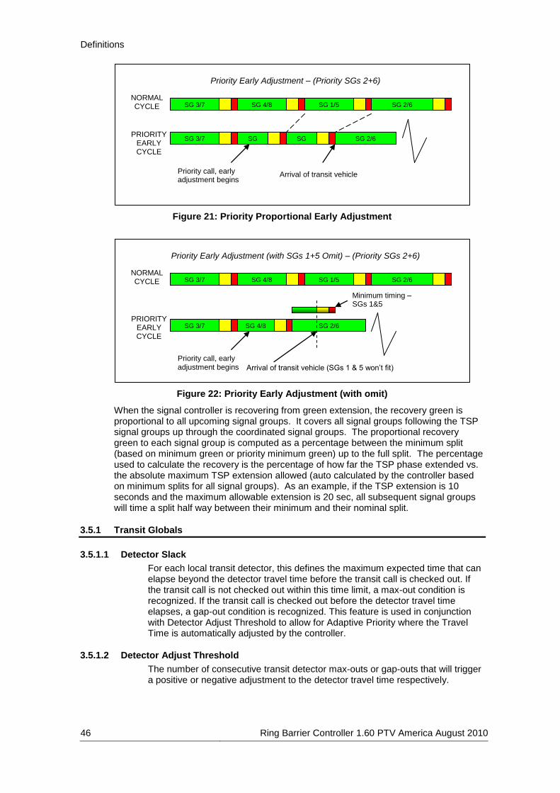
Definitions
46 Ring Barrier Controller 1.60 PTV America August 2010
Figure 21: Priority Proportional Early Adjustment
Figure 22: Priority Early Adjustment (with omit)
When the signal controller is recovering from green extension, the recovery green is proportional to all upcoming signal groups. It covers all signal groups following the TSP signal groups up through the coordinated signal groups. The proportional recovery green to each signal group is computed as a percentage between the minimum split (based on minimum green or priority minimum green) up to the full split. The percentage used to calculate the recovery is the percentage of how far the TSP phase extended vs. the absolute maximum TSP extension allowed (auto calculated by the controller based on minimum splits for all signal groups). As an example, if the TSP extension is 10 seconds and the maximum allowable extension is 20 sec, all subsequent signal groups will time a split half way between their minimum and their nominal split.
3.5.1 Transit Globals
3.5.1.1 Detector Slack
For each local transit detector, this defines the maximum expected time that can elapse beyond the detector travel time before the transit call is checked out. If the transit call is not checked out within this time limit, a max-out condition is recognized. If the transit call is checked out before the detector travel time elapses, a gap-out condition is recognized. This feature is used in conjunction with Detector Adjust Threshold to allow for Adaptive Priority where the Travel Time is automatically adjusted by the controller.
3.5.1.2 Detector Adjust Threshold
The number of consecutive transit detector max-outs or gap-outs that will trigger a positive or negative adjustment to the detector travel time respectively.
Arrival of transit vehicle (SGs 1 & 5 won’t fit)
NORMAL CYCLE SG 1/5 SG 2/6 SG 4/8 SG 3/7
Priority Early Adjustment (with SGs 1+5 Omit) – (Priority SGs 2+6)
Priority call, early adjustment begins
PRIORITY EARLY CYCLE
SG 3/7 SG 2/6 SG 4/8
Minimum timing – SGs 1&5
Arrival of transit vehicle
NORMAL CYCLE SG 1/5 SG 2/6 SG 4/8 SG 3/7
Priority Early Adjustment – (Priority SGs 2+6)
Priority call, early adjustment begins
PRIORITY EARLY CYCLE
SG 3/7 SG 1/5
SG 2/6 SG 4/8

Definitions
Ring Barrier Controller 1.60 PTV America August 2010 47
3.5.1.3 Free Alt. Sequence
Determines which alternate sequence, if any, the controller is allowed to use during transit priority service. The alternate sequence will only be activated if the controller determines that abbreviating the signal group green times will not enable the transit signal groups to serve in time for the arriving transit vehicle. The alternate sequence can not be activated if any signal group that is to be repositioned is either timing or next. The alternate sequence is defined by a Pattern, but only the Lead values within that pattern are used.
3.5.1.4 Coord. Alt. Sequence
This parameter determines which alternate sequence, if any, the controller is allowed to use during transit priority service. The alternate sequence will only be activated if the controller determines that abbreviating the signal group green times will not enable the transit signal groups to serve in time for the arriving transit vehicle. The alternate sequence can not be activated if any signal group that is to be repositioned is either timing or next.
3.5.2 Transit SGs
3.5.2.1 Transit SG
There are 8 Transit SGs available. The signal groups numbers for transit priority are hard coded as SG 301-308. The signal groups are not necessary for transit priority to be used, but allow additional flexibility if you wish to have a separate signal head for the Transit Priority movement. The Transit SGs will not be available within VISSIM unless you select Use as VISSIM SG.
3.5.2.2 Use as VISSIM SG
If this option is selected, the corresponding signal group will be passed to VISSIM and therefore available to be referenced to with a signal head.
3.5.2.3 Parent SGs
These are the signal groups that must be timing for the transit priority to time. All signal groups flagged for this parameter must be timing before the transit priority can time; this is unlike overlaps that can time when any parent signal group times. Signal Groups that conflict with parent signal groups will not begin timing until the transit priority has completed timing its clearance intervals.

Definitions
48 Ring Barrier Controller 1.60 PTV America August 2010
Figure 23: Transit SG Parent SG Configuration
3.5.2.4 No Call SGs
Normally when there is a call for a transit priority, all Parent SGs will be called since the transit priority must time with its Parent SGs. Any signal groups flagged for this parameter will not be called when the associated transit priority has a call.
3.5.2.5 Priority SGs
These are the signal groups that the controller will choose as the priority movements that will serve concurrently with the Transit SG. If this parameter is left undefined, the controller will choose the Parent SGs as the priority movements.
3.5.2.6 Min green
This parameter defines the minimum green time that a Transit SG will serve before changing to yellow. In the absence of any extension, the Transit SG will serve this minimum green time before it is eligible to terminate. The controller will enforce a minimum green time of 1.0 seconds if the value of this parameter is less than 1.0 seconds. The minimum green time can be abbreviated to the Start Green time of an active preempt. If any of the Parent SGs are flagged for Zero SG Green Time for an active preempt, the minimum green time will be aborted for the Transit SG. Values permitted are zero to 25.5 seconds.
3.5.2.7 Yellow
The time a Transit SG will time a yellow indication before advancing to red. This time can not be abbreviated by any operation. Values permitted are zero to 25.5 seconds.
3.5.2.8 Red Clearance
The time a Transit SG will time a red indication before any signal groups that conflict with its Parent SGs will be allowed to begin timing. Values permitted are zero to 25.5 seconds.
Priority begins with last parent to start
SG 2
Transit SG – Single Ring Parents (SG 2)
Transit SG – Dual Ring Parents (SGs 2+6)
SG 1
SG 5 SG 6
LRV
Priority ends with first parent to end
SG 2 SG 1
SG 5 SG 6
LRV Priority times with its sole parent SG

Definitions
Ring Barrier Controller 1.60 PTV America August 2010 49
3.5.2.9 Adv. Call Time
Once the Transit SG travel timer (estimated time until arrival at the intersection) is equal to or less than this value, a call will be placed to serve the Transit SG. When the Transit SG has the Priority Mode enabled, the Advanced Call Time will be subtracted from the Travel Time to compute the target transit green time. This will attempt to display a green indication on the Transit SG in advance of the actual arrival of the transit vehicle. Values permitted are zero to 255 seconds.
3.5.2.10 Extension
This parameter defines the time that a Transit SG will extend its green interval following the dropped detection (either loss of presence on a Presence detector or Check Out on a Check In/Check Out detector). During this extension, the Transit SG will remain green unless Parent SGs are terminating before the extension expires. Values permitted are zero to 255 seconds.
3.5.2.11 Call Mode (Recall, Locked, Non-locked, Soft Recall)
Determines how a Transit SG is called. As with regular signal groups, a Transit SG will not turn green unless it receives a call. The call modes are:
► Recall – The Transit SG will receive an automatic call without any detector actuation, and will place calls on all Parent SGs. The transit signal will change green whenever all Parent SGs are green.
► Locked – transit detectors will place a locked call to the Transit SG anytime there is an actuation. Calls that are dropped on Presence detectors or Check In/Check Out detectors will still call the Transit SG until it is served. Parent SGs will receive a call until the Transit SG is served.
► Non-Locked – transit detectors will place a call to the Transit SG anytime there is an actuation, but will not lock the call. While the call is present, Parent SGs will receive a call.
► Soft Recall – The Transit SG will not place an automatic call for itself or its Parent SGs. If all Parent SGs are green, the transit signal will still change green.
3.5.2.12 Priority
By default, transit priority requests with lower estimated travel times are served ahead of transit priority requests with higher estimated travel times. For higher priority transit movements, the Priority should be defined to a higher value than that of lower priority transit movements. Transit movements with higher Priority values (regardless of estimated travel time) will be served ahead of those with lower Priority values. Values permitted are zero to 255.
3.5.2.13 Reservice Inh. Same
If programmed to a non-zero value, the transit signal group will not be given any priority service for the Reservice Inhibit Same time following the last service. Note that the transit signal group may still receive non-priority service if all parent signal groups are green before the Reservice Inhibit Same time has expired.
3.5.2.14 Reservice Inh. All
If programmed to a non-zero value, no transit signal group will be given any priority service for the Reservice Inhibit All time following the last service. Note that any transit signal group may still receive non-priority service if its parent signal groups are green before the Reservice Inhibit All time has expired.

Definitions
50 Ring Barrier Controller 1.60 PTV America August 2010
3.5.3 Coordination Priority
3.5.3.1 Vehicle SG Omits
This parameter is only observed when the controller is operating in the coordinated mode. If the controller can not serve the greater of a Min Green or Priority Min Green (for the active coordination pattern) on a signal group that conflicts with a Transit SG and still serve the Transit SG by the end of the travel time, it will omit the signal group if the signal group is flagged for this parameter. When computing whether the controller can serve the signal group, it takes into account the time required by all signal groups that must time prior to the priority service.
3.5.3.2 Ped SG Omits
This parameter is only observed when the controller is operating in the coordinated mode. If the controller can not serve a pedestrian signal group that conflicts with a Transit SG and still serve the Transit SG by the end of the travel time, it will omit the pedestrian signal group if the signal group is flagged for this parameter. When computing whether the controller can serve the signal group, it takes into account the time required by all signal groups that must time prior to the priority service.
3.5.3.3 Priority Mode
This parameter defines the priority mode of the Transit SG. This parameter is only observed when the controller is operating in the coordinated mode. The modes are:
► None – The Transit SG will not adjust any controller operation in order to achieve priority service.
► Early/Extend – The Transit SG may adjust signal group timing and sequencing based on the parameters defined in this section in order to achieve priority service. Signal group split adjustments can be made to allow for either an early return to or extension of the priority Parent SGs.
► Extend Only – The Transit SG may adjust signal group timing and sequencing based on the parameters defined in this section in order to achieve priority service. Signal group split adjustments will only be made to allow for an extension of the priority Parent SGs.
3.5.3.4 Extend Limit
This parameter is only observed when the controller is operating in the coordinated mode. When using a Coordinated Priority Mode other than None, this is the maximum time that a Transit SG will be allowed to extend its Parent SGs beyond their normal coordinated force-off times before the priority extension will be aborted. Values permitted are zero to 255 seconds.
3.5.3.5 Priority Min Green
When a signal group that conflicts with a priority signal group is timing, the controller will abbreviate it in order to serve the Priority SGs faster. Normally, the controller will be allowed to shorten the conflicting signal group down to its Min Green time before terminating the signal group. Programming a non-zero value for this parameter will guarantee the longer of the signal group Min Green or Priority Minimum Green time before it will be terminated to serve a priority signal group. Values permitted are zero to 255 seconds.
3.5.3.6 Recovery Min Green
When computing the maximum duration for a priority extension, the controller will take into account the minimum timing for each signal group in the recovery

Definitions
Ring Barrier Controller 1.60 PTV America August 2010 51
cycle (the cycle following the priority extension). The controller can only extend the Priority SGs to the point where it can still serve the greater of the Min Green time or Recovery Minimum Green time to all subsequent signal groups by the end of the next cycle.
Figure 24: Priority Minimum Green and Recovery Minimum Green
3.5.3.7 Priority Progression
This parameter modifies how coordinated signal group splits are shortened during a priority request. Any coordinated signal group flagged for this parameter will guarantee a minimum green band from the computed start of signal group green. Without this parameter, coordinated signal groups can be terminated at the computed start of green provided they have been green for the priority minimum green. Flagging coordinated signal groups with this parameter improves vehicular progression, but limits how much the current cycle can be abbreviated in order to serve an early priority request in the next cycle.
3.5.4 Free Running Priority
3.5.4.1 Vehicle SG Omits
This parameter is only observed when the controller is operating in Free mode. If the controller can not serve the greater of a Min Green or Priority Min Green on a signal group that conflicts with a Transit SG and still serve the Transit SG by the end of the travel time, it will omit the signal group if the signal group is flagged for this parameter. When computing whether the controller can serve the signal group, it takes into account the time required by all signal groups that must time prior to the priority service.
3.5.4.2 Ped SG Omits
This parameter is only observed when the controller is operating in Free mode. If the controller can not serve a pedestrian signal group that conflicts with a Transit SG and still serve the Transit SG by the end of the travel time, it will omit the pedestrian signal group if the signal group is flagged for this parameter. When
Priority Extension
NORMAL CYCLE SG 1/5 SG 2/6
(COORD) SG 4/8 SG 3/7
SG 1/5
SG 2/6
SG 4/8
SG 3/7
Priority Minimum Green / Recovery Minimum Green – (Priority SGs 2+6)
Maximum Extension, recovery begins
PRIORITY/ RECOVERY
CYCLE
Recovery Cycle (using Recovery Minimum Greens)
SG 1/5 SG 4/8 SG 3/7 SG 2/6 (COORD)
Minimum green
EARLY PRIORITY
CYCLE
Priority Minimum Green
Minimum Cycle (using minimum green times)
Recovery Minimum Green
SG Minimum Green

Definitions
52 Ring Barrier Controller 1.60 PTV America August 2010
computing whether the controller can serve the signal group, it takes into account the time required by all signal groups that must time prior to the priority service.
3.5.4.3 Priority Mode
This parameter defines the priority mode of the Transit SG. This parameter is only observed when the controller is operating in the Free mode. The modes are:
► None – The Transit SG will not adjust any controller operation in order to achieve priority service.
► Early/Extend – The Transit SG may adjust signal group timing and sequencing based on the parameters defined in this section in order to achieve priority service. Signal group maximum times may be adjusted to allow for either an early return to or extension of the priority Parent SGs.
► Extend Only – The Transit SG may adjust signal group timing and sequencing based on the parameters defined in this section in order to achieve priority service. Signal group maximum times may be adjusted to allow for an extension of the priority Parent SGs.
3.5.4.4 Recovery Mode
This feature defines the Recovery Mode of the Transit signal group following priority service. This parameter is only observed when the controller is operating in the Free mode. The free recovery modes are:
► Normal – Following the priority service, the controller will continue timing normally from the currently timing signal groups.
► ServeOmit – If any signal groups were omitted during the transit priority service, the controller will return to the first signal groups that were omitted. If no signal groups were omitted, the controller will continue timing normally from the currently timing signal groups.
3.5.4.5 Extend Limit
This parameter is only observed when the controller is operating in Free mode. When using a Free Priority Mode other than None, this is the maximum time that an Transit SG will be allowed to extend once the associated Transit SG changes green and the arrival timer counts down to zero. Note that the Transit SG may be passively extended if all Parent SGs still have enough time remaining beyond the priority extension limit. Values permitted are zero to 255 seconds.
3.5.4.6 Priority Min Green
When a signal group that conflicts with a priority signal group is timing, the controller will abbreviate it in order to serve the priority signal group faster. Normally, the controller will be allowed to shorten the conflicting signal group down to its Min Green time before terminating the signal group. Programming a non-zero value for this parameter will guarantee the longer of the signal group Min Green or Priority Minimum Green time before it will be terminated to serve a priority signal group. Values permitted are zero to 255 seconds.
3.5.5 Transit Inputs
3.5.5.1 Inputs
These are internal transit input ID numbers.

Definitions
Ring Barrier Controller 1.60 PTV America August 2010 53
3.5.5.2 Call
Signal groups that receive a vehicle call and extension while the transit detector input is on. It is not necessary to flag the transit Parent SGs since any Transit SG with a call will automatically call its Parent SGs.
3.5.5.3 Call Transit SGs
This parameter defines the Transit SGs that are called and extended while the transit detector input is on.
3.5.5.4 Checkout Detectors
Additional transit inputs that will automatically be “checked out” when this transit detector receives a check-out call.
3.5.5.5 Delay time
The amount of time a detector input must have continuous presence before placing a call to Call Transit SGs and Call signal groups. Values permitted are zero to 25.5 seconds.
3.5.5.6 Extend time
The amount of time that the transit detector will continue to extend Call Transit SGs and Call signal groups after the transit detector input transitions from on to off. Values permitted are zero to 25.5 seconds.
3.5.5.7 Travel Time
The estimated time it will take the transit vehicle to arrive at the intersection once it passes this transit detector. This travel time will be used to adjust intersection timing if priority service is enabled for this Transit SG. Values permitted are zero to 255 seconds.
3.5.5.8 Travel Time Slack
The Travel Time Slack is a parameter that identifies the uncertainty of the actual travel time of the transit vehicle from the local detector to the intersection. The value entered for this parameter is the average length of time beyond the local detector Travel Time that the transit vehicle is expected to arrive at the intersection. In effect, once the transit vehicle passes the detector, it is expected to arrive at the intersection as soon as the Travel Time or as late as the Travel Time PLUS the Travel Time Slack. This parameter is only used when the controller is making a decision whether or not to extend Priority SGs due to a call from the local transit detector. Assuming the Transit SG linked to this transit detector is eligible for priority service, a priority extension can occur as long as the Priority SGs can be extended for a transit vehicle that will arrive at the end of the slack time (Travel Time PLUS Travel Time Slack). Values permitted are zero to 255 seconds.
3.5.5.9 Travel Timing
If the transit vehicle TRAVEL TIME + SLACK (estimated “lateness”) can be served by the end of the maximum priority extension period, the controller will allow the extension. Otherwise, the controller will choose to go through early priority, essentially abbreviating all upcoming SGs and attempting to return early the following cycle to accommodate the transit vehicle.

Definitions
54 Ring Barrier Controller 1.60 PTV America August 2010
Figure 25: Travel Time and Travel Time Slack
3.5.5.10 Adjust Step
After a threshold (Detector Adjust Threshold) of consecutive max-outs, the detector travel time will be increased by the current Adjust Step. After the same threshold of consecutive gap-outs, the detector travel time will be decreased by the current Adjust Step.
3.5.5.11 Adjust Max
The incremental adjustments to the local detector travel time will never exceed the Adjustment Max (i.e. a value or 10 will allow the local detector travel time to be increased by up to 10 seconds above the programmed travel time).
3.5.5.12 Calling Point Detector
This parameter defines whether or not the Check In detector is a Calling Point Detector or not.
3.5.5.13 Lateness
This parameter defines the threshold value in minutes for lateness in order to receive priority. Lateness is only used with Calling Point Detectors. The vehicle must be later than the defined lateness value in order to receive priority. Values permitted are -600 to 600 seconds.
3.5.5.14 Check Out Limit
This parameter defines the time that a transit Check In detector will remain on before automatically being checked-out (in case the transit Check Out detector isn’t triggered). Setting this parameter to zero disables the automatic check-out for the transit detector. Once a Check In detector has been triggered, the check-out limit timer will be reset for each additional check-in actuation. Values permitted are zero to 65535 seconds.
3.5.5.15 Check Out Mode
Determines the mode of the transit check-out detector: 1) Normal – The Transit SG will be checked-out as soon as the Check Out detector is activated. 2) StopBar – When the Check Out detector is activated, a check-in call will be placed to the Transit SG. Once the Check Out detector is deactivated (transit vehicle departs from the detector zone), the Transit SG will be checked-out.
3.5.5.16 Detector Type
This parameter determines which type of detector will be defined for the input and which detector number(s) will be shown for the input Presence detector number or Check In/Check Out detector numbers.
TRAVEL TIME TRAVEL TIME + SLACK
Normal parent SG termination
SG 2
SG 6
Transit (parents 2+6)
Maximum allowable priority extension

Definitions
Ring Barrier Controller 1.60 PTV America August 2010 55
3.5.5.17 Presence
Presence detector number to be used within VISSIM for the corresponding Transit input; numbers hard coded as numbers 301-308. Calls using this detector number will be lost when the vehicle leaves the detector.
3.5.5.18 Check In
Detector number to be used within VISSIM for the corresponding Transit input; numbers are predefined as numbers 311-318 but can be edited. Calls using this detector number will place a check in call with the Transit SG; the call remains checked in until the corresponding Check Out detector gets a call.
3.5.5.19 Check Out
Detector number to be used within VISSIM for the corresponding Transit input; numbers hard coded as numbers 321-328. Calls using this detector number will check out the Transit SG.

Examples
56 Ring Barrier Controller 1.60 PTV America August 2010
4 Examples
4.1 Coordinated Signal
This section describes the inputs to use for an 8-signal group fixed time coordinated signal operating with a 110-second cycle length. This example uses the minimum features necessary for this type of signal control and only those features are displayed in the timing figures below, opening the fixedcoordinated.ini settings file within the RBC dialog will allow you to see the timing in the same format as in the figures. Features of this example include:
► Controller frequency of 2;
► 8 vehicle signal groups;
► 2 overlap signal groups;
► 4 pedestrian signal groups;
► Left-turns are all protected and leading;
► Dual entry is set for through movements;
► The local zero point in the cycle is defined as Lead Green which is the start of green of the first coordinated signal group;
► 35-second offset to master controller from the local zero point; and
► Pedestrian signal groups have pushbuttons.
Figure 26: Timing for Signal Controller 1
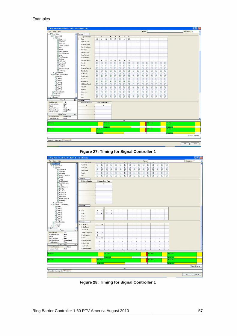
Examples
Ring Barrier Controller 1.60 PTV America August 2010 57
Figure 27: Timing for Signal Controller 1
Figure 28: Timing for Signal Controller 1

Examples
58 Ring Barrier Controller 1.60 PTV America August 2010
Figure 29: Signal Head Placement for Signal Controller 1

Examples
Ring Barrier Controller 1.60 PTV America August 2010 59
4.2 Free Running Signal
This section describes the inputs to use for a T-shaped fully-actuated Free Running signal. This example uses the minimum features necessary for this type of signal control and only those features are displayed in the timing figures below, opening the Free.ini settings file within the RBC dialog will allow you to see the timing in the same format as in the figures. Features of this example include:
► Controller frequency of 2;
► 4 vehicle signal groups, 1 overlap signal group;
► 2 pedestrian signal groups;
► Dual entry is set for signal groups 4 & 8;
► Protected left-turn (signal group 3) is leading;
► Vehicle Signal Groups 2, 3, 4, and 8 are all actuated and have detectors that call and extend the signal groups; and
► All pedestrian signal groups have pushbuttons.
Figure 30: Timing for Signal Controller 2

Examples
60 Ring Barrier Controller 1.60 PTV America August 2010
Figure 31: Timing for Signal Controller 2
Figure 32: Signal Head & Detector Placement for Signal Controller 2

Examples
Ring Barrier Controller 1.60 PTV America August 2010 61
4.3 Signal with Plan Change
This signal controller changes plans twice during the simulation. This example uses the minimum features necessary for this type of signal control and only those features are displayed in the timing figures below, opening the planchange.ini settings file within the RBC dialog will allow you to see the timing in the same format as in the figures. Features of this example include:
► Controller frequency of 2;
► 8 vehicle signal groups;
► 2 pedestrian signal groups;
► Signal Groups 4 and 8 are set to maximum recall;
► Pedestrian signal groups 102 and 106 have pushbuttons;
► Vehicle Signal Groups 1, 2, 3, 5, 6, and 7 are all actuated and have detectors that call and extend the signal groups;
► Protected left turns north and south bound;
► Protected/Permitted Phasing: left turns east and west bound and right turns north and south bound;
► Starts in Free Running Mode;
► Two Patterns;
► Pattern 1 is coordinated and starts at simulation second 600;
► Pattern 2 is Free Running, uses Max2 green times, and starts at simulation second 1500;
► Left-turns are all leading for Base Timing and Pattern 1;
► Signal Groups 3 and 7 are lagging for Pattern 2;
► For Pattern 1, the local zero point in the cycle is defined as Lead Green which is the start of green of the first coordinated signal group;
► For Pattern 1, 35-second offset to master controller from the local zero point;
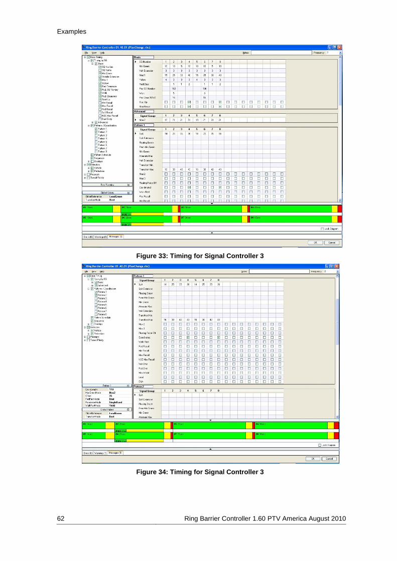
Examples
62 Ring Barrier Controller 1.60 PTV America August 2010
Figure 33: Timing for Signal Controller 3
Figure 34: Timing for Signal Controller 3

Examples
Ring Barrier Controller 1.60 PTV America August 2010 63
Figure 35: Timing for Signal Controller 3
Figure 36: Timing for Signal Controller 3

Examples
64 Ring Barrier Controller 1.60 PTV America August 2010
Figure 37: Signal Head & Detector Placement for Signal Controller 3

Examples
Ring Barrier Controller 1.60 PTV America August 2010 65
4.4 Preempt
The Rail Road Preemption settings described in this section only controls an intersection near a rail road crossing. The rail road gate will require an additional signal controller. The RR Gate Crossing VAP shown in this example is intended for this use. The two are meant to be used in conjunction; however, the RR Gate Crossing may be used alone. During Clearance, traffic blocking the tracks is cleared from the intersection before the train arrives. Dwell occurs while the train is crossing the intersection and allows traffic that is non-conflicting with the train to continue. Opening the Preempt.ini settings file within the RBC dialog will allow you to see the timing in the same format as in the figures. Features of this example include:
► Controller frequency of 1 (the VAP used in this example for the Gate uses 1);
► 3 vehicle signal groups;
► Vehicle Signal Groups 2, 4, and 8 are all actuated and have detectors that call and extend the signal groups;
► Preempt Inputs 1 & 2 are used, 1 for North Bound and 2 for South Bound;
► Check In/Check Out detection for Preempt;
► The Gate VAP uses Presence detection;
► Signal Group 2 is coordinated;
► Cycle length is 110 seconds;
► Offset is 0 and is referenced to LeadGreen;
► Exit mode is In Step;
► Zero SG Green is set for signal groups 2 & 4 (this causes the signal to immediately go to clearance for these signal groups when the Preempt triggers the Check In detector.);
► Track Clearance 1 is used to clear the West Bound movement, and is 12 seconds; and
► Signal Group 2 is a Dwell SG, allowed to run with the Preempt.
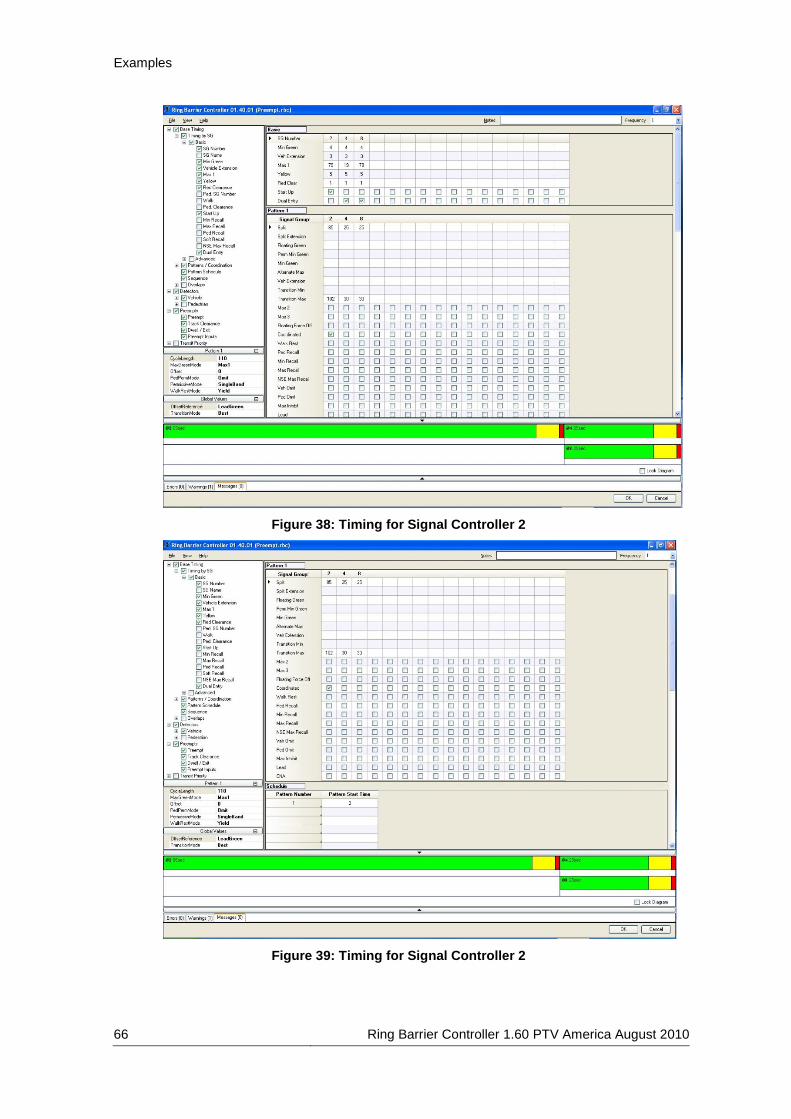
Examples
66 Ring Barrier Controller 1.60 PTV America August 2010
Figure 38: Timing for Signal Controller 2
Figure 39: Timing for Signal Controller 2

Examples
Ring Barrier Controller 1.60 PTV America August 2010 67
Figure 40: Timing for Signal Controller 2
Figure 41: Timing for Signal Controller 2

Examples
68 Ring Barrier Controller 1.60 PTV America August 2010
Figure 42: Signal Head & Detector Placement for Signal Controller 2
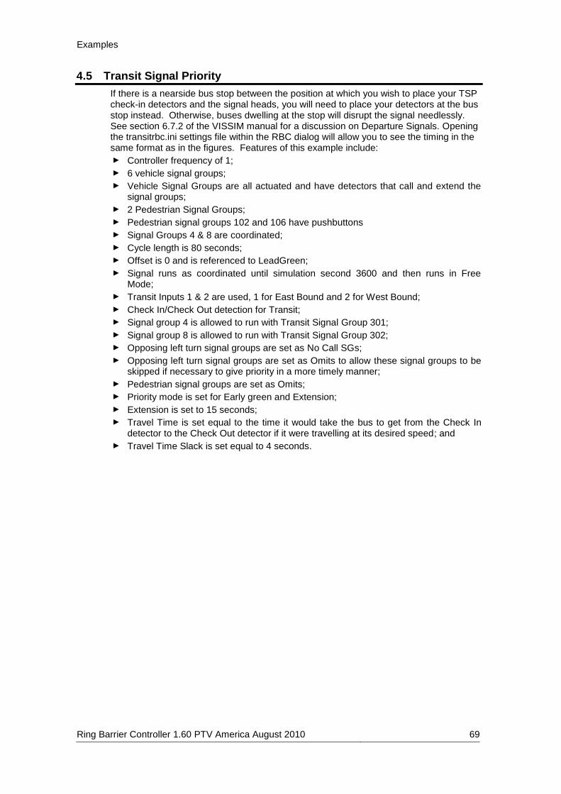
Examples
Ring Barrier Controller 1.60 PTV America August 2010 69
4.5 Transit Signal Priority
If there is a nearside bus stop between the position at which you wish to place your TSP check-in detectors and the signal heads, you will need to place your detectors at the bus stop instead. Otherwise, buses dwelling at the stop will disrupt the signal needlessly. See section 6.7.2 of the VISSIM manual for a discussion on Departure Signals. Opening the transitrbc.ini settings file within the RBC dialog will allow you to see the timing in the same format as in the figures. Features of this example include:
► Controller frequency of 1;
► 6 vehicle signal groups;
► Vehicle Signal Groups are all actuated and have detectors that call and extend the signal groups;
► 2 Pedestrian Signal Groups;
► Pedestrian signal groups 102 and 106 have pushbuttons
► Signal Groups 4 & 8 are coordinated;
► Cycle length is 80 seconds;
► Offset is 0 and is referenced to LeadGreen;
► Signal runs as coordinated until simulation second 3600 and then runs in Free Mode;
► Transit Inputs 1 & 2 are used, 1 for East Bound and 2 for West Bound;
► Check In/Check Out detection for Transit;
► Signal group 4 is allowed to run with Transit Signal Group 301;
► Signal group 8 is allowed to run with Transit Signal Group 302;
► Opposing left turn signal groups are set as No Call SGs;
► Opposing left turn signal groups are set as Omits to allow these signal groups to be skipped if necessary to give priority in a more timely manner;
► Pedestrian signal groups are set as Omits;
► Priority mode is set for Early green and Extension;
► Extension is set to 15 seconds;
► Travel Time is set equal to the time it would take the bus to get from the Check In detector to the Check Out detector if it were travelling at its desired speed; and
► Travel Time Slack is set equal to 4 seconds.

Examples
70 Ring Barrier Controller 1.60 PTV America August 2010
Figure 43: Timing for Signal Controller 1
Figure 44: Timing for Signal Controller 1
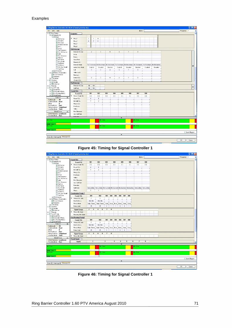
Examples
Ring Barrier Controller 1.60 PTV America August 2010 71
Figure 45: Timing for Signal Controller 1
Figure 46: Timing for Signal Controller 1

Examples
72 Ring Barrier Controller 1.60 PTV America August 2010
Figure 47: Timing for Signal Controller 1
Figure 48: Detector Placement for Signal Controller 1

Troubleshooting / Services
Ring Barrier Controller 1.60 PTV America August 2010 73
5 Troubleshooting / Services
5.1 Troubleshooting
5.1.1 Errors
5.1.1.1 Inconsistent Cycle Length
Description: If the plan is coordinated, then the cycle length must match the cumulative length of the splits, or else the cycle length is inconsistent. Message: "The cycle length:# for Pattern:# does not match the accumulated split length:#. This may cause problems in the simulation."
5.1.2 Warnings
5.1.2.1 Invalid Coordination Among Ring Barrier Diagram:
Description: If any signal group is coordinated, then there must be at least one other signal group in the same barrier for each ring used, or else the coordination is invalid. Message: "SG:# has been marked as coordinated, and was placed in ring:#, barrier:#. However ring:# does not contain any other SG in barrier:# that is also coordinated. The signal will run in free mode unless at least one coordinated SG exists in each ring."
5.1.2.2 Invalid Walk Rest Coordination:
Description: Walk rest mode is only possible for coordinated signal groups, so if a signal group has walk rest mode checked, but does not have coordinated checked, then the walk rest mode is invalid. Message: "Walk Rest Mode is only possible for coordinated SG's, however the SG:# has been checked for WalkRest, but not for coordinated. WalkRest will be ignored unless the coordinated box is checked.
5.1.2.3 Initial Enable Inconsistency:
Description: If values are set for added initial or max initial, then the corresponding detector should be flagged as initial enabled, too, or else the initial enable settings are inconsistent. Message: "[Added Initial | Max Initial] has been set for SG:#, but vehDetector:# uses that SG, and does not have AddedInitial enabled. The mode must be enabled in order to work as added initial."
5.1.2.4 Non Standard Frequency:
Description: The default frequency is “1” (once per simulation second), but if it is to something other than that, VISSIM’s simulation resolution must be set to at least that speed in order for the simulation to run. Message: "The simulation resolution in VISSIM must be greater than or equal to the controller frequency in order for the simulation to run. Make sure you set it to at least # before you run it."

Troubleshooting / Services
74 Ring Barrier Controller 1.60 PTV America August 2010
5.1.2.5 Surpassed Min Green Length:
Description: If a signal group has a length less than its respective min green time, then that green time will be superseded by the min green time, which is not reflected in the timing diagram. Message: "SG:# has a MaxGreen of #s, but a MinGreen of #s. The MinGreen will supersede the Max." or… "Pattern:# uses SG:# with a MaxGreen of #s, but a MinGreen of #s. The MinGreen will supersede the Max." or… "Pattern:# uses SG:# with a Split of #s, with available green time of #s, but its MinGreen is #s. The MinGreen will supersede the allotted green time."
5.1.2.6 Zero Splits:
Description: If a coordinated signal group has a split time of 0, the controller will actually give it a split value, but it may not be what is desired or expected. Message: "Pattern:# uses SG:#, which is coordinated, but has a split of 0. The controller will determine the split time automatically, but it may not be what is desired, or expected."
5.1.2.7 Ped-Signal group Out Of Bounds:
Description: An entire ped signal group (walk AND ped clearance) must fit within the green portion of its corresponding signal group. The diagram will allow it, but it will not simulate that way. Thus, the ped signal group is said to be out of bounds. Message: "In Free Running Mode with no pattern definded, PedSG:# has length of #s, but the SG:# that it is attached to has a green time of #s. The ped timing cannot exceed that limit.” or… Pattern:# uses PedSG:#, which has a length of #s, but the SG:# that it is attached to has a green time of #s. The ped timing cannot exceed that limit."
5.1.2.8 Ambiguously Scheduled Patterns:
Description: If two or more patterns are placed in the pattern schedule with the same start time, then the placement farthest down the list will actually run, and the other(s) will not. This might not be what the user intends. Message: "Pattern Schedule has overlapping start times (t=#sec) for rows {#, #,..., #}. Only the last one will take effect."
5.1.2.9 Changed Order SGs:
Description: If a signal group at save is not in the same column as it was on load, then any signal heads, stops signs and priority rules that use this signal group will be updated to use the new signal group number from that column, and the user is warned. Message: "Signal Group Column ### had its SG changed from ### to ###. This will update any signal group associations to signal heads, stop signs, etc. for the original signal group number to the new number within VISSIM."
5.1.2.10 License Level:
Description: If the license level is something other than 3, then the user will have limited functionality. Message: "Your license level does not support any functionality." or… "Your license level does not support Preempts or Transit Priority. Values set in these tables will be ignored during simulation." or…

Troubleshooting / Services
Ring Barrier Controller 1.60 PTV America August 2010 75
Your license level does not support Transit Priority. Values set in this table will be ignored during simulation." or… Your license level has somehow become corrupted, and it is not recognized as being valid."
5.1.2.11 Conflict Out of Bounds:
Description: If a signal group is not defined for a column, but the corresponding column index references a conflict, then the user is warned. Message: "No signal groups have been defined for columns ### or ###, but these are set as conflicting." or… "No signal group has been defined for columns ###, but it is set as conflicting with SG: ###."
5.1.3 Messages
5.1.3.1 Settings Saved:
Description: Informs the user that their user settings have been successfully saved. If the settings could NOT be saved, then an error message is written instead. Message: "Settings saved"
5.1.3.2 OVLTiming SG Alert:
Description: Alerts the user that the signal group number which was just entered is invalid because it is a duplicate, and thus will be reverted. Message: "The SG number:### is already in use. Original value is being reverted."
5.1.3.3 Basic SG Alert:
Description: Alerts the user that the signal group number which was just entered is invalid because it is a duplicate, and thus will be reverted. Message: "The SG number:### is already in use. Original value is being reverted."
5.1.3.4 Batch Convert Messages:
Description: These messages only get written if there is an error in the batch convert (from NEMA to RBC) process... Message: <unique depending on the code block and error >: during initialization, during inp reading, during conversion, during overwrite of an existing file, at the end of the process (describing the overall success of the conversion), anything not already handled by these other blocks> NEMA to RBC Conversion Messages (single file): Description: These messages are also code block/error dependent... Message: <for trying to overwrite an existing file, in the overall conversion process, if the > RRPPThreshold value is > 0, if the syntax of the read file does not match what is expected,

Troubleshooting / Services
76 Ring Barrier Controller 1.60 PTV America August 2010
if the actual number of overlaps isn't what is expected, if the LMD_TP value value is > 0, if some unhandled type value is > 0, if conversion from string to array fails>
5.1.3.5 File I/O Messages:
Description: These messages are also code block/error dependent... Message: <if creating the backup file fails, if saving the rbc file fails, if opening the rbc file fails, if saving the settings file fails, if loading the settings file fails>

Troubleshooting / Services
Ring Barrier Controller 1.60 PTV America August 2010 77
5.2 Services
5.2.1 Links
5.2.1.1 Website
PTV America's website is at: http://www.ptvamerica.com.
5.2.1.2 Training
PTV offers training classes both for new and advanced users. Classes can be arranged as training-on-the-job at whatever location you prefer, or you may join one of our set training sessions. Details are available on our websites at http://www.ptvamerica.com/training/.
5.2.1.3 FAQ
At http://www.ptvamerica.com/support/vissim/vissim-faq/ you can find a wide selection of FAQ (frequently asked questions) on VISSIM. For all clients with a software maintenance contract, an extended range of FAQ is available after entering the password supplied with the program license (see letter of delivery with your VISSIM package).
5.2.1.4 Service Packs
For all clients with a software maintenance contract, service packs of the latest VISSIM version are available for download at: http://cgi.ptv.de/cgi-bin/en/traffic/vissim_download.pl. Please note that service packs can be used with the latest VISSIM version only. In the download area on our website you can also register for an automatic e-mail notification whenever a new VISSIM service pack is available.
5.2.2 Technical Support
You may access our technical support hotline service from here: http://www.ptvamerica.com/support/technical-support-hotline/ or you can email us directly at [email protected].