Embed Size (px)
Citation preview

Technical DataOriginal Instructions
RightSight M30Catalog Numbers 42AF-P2MAB1-F4, 42AF-P2MAB1-D4, 42AF-P2RHB1-G4, 42AF-E1EZB1-F4, 42AF-E1EZB1-D4, 42AF-R1MAB1-D4, 42AF-R1MAB1-F4, 42AF-R1RHB1-G4, 42AF-E1UZB1-G4, 42AF-P2CHB1-A2, 42AF-R1CHB1-A2, 42AF-E1UZB1-A2, 42AF-P2SHB1-G4, 42AF-R1SHB1-G4, 42AF-P2CHB1-M5, 42AF-R1CHB1-M5, 42AF-E1UZB1-M4
Summary of Changes
This publication contains the following new or updated information. This list includes substantive updates only and is not intended to reflect all changes.
Description
The RightSight™ M30 family of photoelectric sensors offers high-performance general-purpose sensing in a robust flexible package. They are designed for applications where simplified installation and maintenance are required.
Designed to withstand the rigors of material handling and packaging environments, the RightSight M30 standard models can withstand IP69K high-pressure washdowns.
This family also offers a background reflection/foreground suppression sensing mode that allows you to use the surface of a background (for example, a conveyor) as a reflector. The detection of a target occurs once an object blocks the visual path between the sensor and the background (for example, conveyor).
Available Models• Polarized retroreflective• Transmitted beam• Background suppression• Background reflection
Status Indicators
Topic PageDescription 1Status Indicators 1Features 2Specifications 2Product Selection 3Sensor User Interface 4Wiring 4Approximate Dimensions 5Typical Response Curves 5Accessories 6
Topic PageUpdated Description 1Updated Available Models list 1Updated Features 2Updated Product Selection table and Connection Options Important table that follows 3
Updated Figure 2, Figure 3, Figure 4, and Figure 9 titles 4 and 5Updated Figure 12 5
Orange Indicator
Green Indicator

RightSight M30 Technical Data
Features• Maximum sensing distance
- Background suppression without physical adjustments (a): 400 mm (15.7 in.) and 600 mm (23.6 in.)
- Background suppression with push button teach (a): 1.2 m (3.94 ft)
- Background reflection with push button teach (a): 800 mm (31.5 in.)
- Polarized retroreflective:10 m (32.8 ft) with 92-125 reflector
- Transmitted beam:80 m (262.5 ft)
• High powered light source for ease of alignment• 360° highly visible user interface helps operators verify
the proper operation, regardless of the sensor installation location
• Background suppression performance helps minimize false detections due to highly reflective backgrounds
• Dual Auto PNP/NPN helps streamline inventory by reducing the number of catalog numbers to stock
• Push button lock helps prevent unauthorized operators from changing the sensor settings
• Embedded IO-Link 1.1 communications protocol• Adjustable sensing ranges and response time via IO-Link
provides additional flexibility to detect targets at longer or shorter distances depending on the application requirements.
• IP67 and IP69K rated enclosure.
Specifications
(a) All models can be taught to detect targets up to 4 m (13.1 ft.) when using IO-Link to adjust the response time
Attribute ValueCertifications c-UL-us and CE Marked for all applicable directivesVibration 10…55 Hz, 1 mm (0.04 in.) amplitude, meets, or exceeds 60947-5-2Shock 30 g (1.1 oz) with 1 ms pulse duration per IEC 60947-5-2
Ambient light immunity• Direct Illumination: 20,000 lux• Indirect Illumination: 5000 lux• Sunlight immunity; 108,000 lux
User InterfaceStatus indicators Green and orange light-emitting diodes (LED)ElectricalAdjustments No physical adjustment. IO-Link adjustable
Operating voltage • DC models: 10…30V DC, IO-Link: 18…30V• AC/DC models: AC: 24…250V AC/DC: 20…250V DC
Current consumption 35 mA maxSensor protection DC: Reverse polarity and short circuit; AC/DC: Reverse polarityDiscrete Output
Response time • DC: 1 ms• AC/DC: 15 ms max
Output type • DC: Dual Auto PNP or NPN• AC/DC: EM Relay
Load current• DC: 100 mA max• AC/DC SPDT: 10…30V DC: 3 A; 31…125V DC: 200 mA;
24…250V AC: 3 AIO-LinkCommunications mode COM2Cycle time, min 2 msProcess data bit length 32 bits (4 bytes)Specifications 1.1MechanicalHousing material PBTLens material PMMACover material PolysulfoneReliability Data
Transmitted Beam and Polarized Retroreflective AC/DC
MTTFd (hours) 6548788.474
T10d 78.76
Transmitted Beam and Polarized Retroreflective DC
MTTFd (hours) 9310986.965
T10d 111.9875
Transmitted Beam Emitter AC/DC
MTTFd (hours) 24271844.66
T10d 291.9285467
Transmitted Beam Emitter DC
MTTFd (hours) 24271844.66
T10d 291.9285467
EnvironmentalEnclosure type rating IP67 and IP69K per ISO 20653 rated enclosureOperating temperature -40…+70 °C (31…158 °F) (1)
(1) The sensing range for all sensing modes can be reduced up to 20% when operated between -40…-25 °C (-40…-13 °F).
Connection type
• 2 m (6.5 ft) cable• 4-pin Integral M12 QD• 4-pin M12 QD on a 150 mm (5.9 in.) pigtail• 4-pin mini QD on 150 mm (5.9 in.) pigtail• 5-pin mini QD on 150 mm (5.9 in.) pigtail
2 Rockwell Automation Publication 42AF-TD001B-EN-P - June 2020
RightSight M30 Technical Data
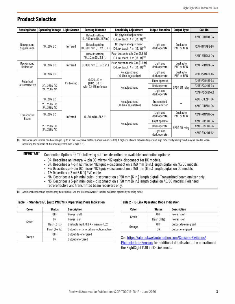
Product Selection
See https://ab.rockwellautomation.com/Sensors-Switches/Photoelectric-Sensors for additional details about the operation of the RightSight M30 in IO-Link mode.
Sensing Mode Operating Voltage Light Source Sensing Distance Sensitivity Adjustment Output Function Output Type Cat. No.
Background Suppression 10...30V DC Infrared
Default setting:10...400 mm (0...15.7 in.)
No physical adjustment. IO-Link teach: 4 m (13.1 ft) (1)
(1) Sensor response time can be changed up to 75 ms to achieve distance of up to 4 m (13.1 ft). A higher distance between target and high reflectivity background may be needed when operating the sensors at distances greater than 2 m (6.6 ft).
Light and dark operate
Dual auto PNP or NPN
42AF-B1MAB1-D4
Default setting:10...600 mm (0...23.6 in.)
No physical adjustment. IO-Link teach: 4 m (13.1 ft) (1) 42AF-B1MAB2-D4
Default setting:10...1.2 m (0...3.9 ft)
Push button teach: 3 m (9.8 ft) IO-Link teach: 4 m (13.1 ft) (1) 42AF-B1MAC1-D4
Background Reflection 10...30V DC Infrared 0...800 mm (0...31.5 in.) Push button teach: 3 m (9.8 ft)
IO-Link teach: 4 m (13.1 ft) (1)Light and
dark operateDual auto
PNP or NPN 42AF-N1MAC1-D4
Polarized Retroreflective
10...30V DC
Visible red0.025...10 m(0.03...33 ft)
with 92-125 reflector
No adjustment(IO-Link adjustable)
Light and dark operate
Dual auto PNP or NPN 42AF-P2MAB1-D4
20...250V DC 24...250V AC No adjustment
Light operate
SPDT EM relay
42AF-P2RHB1-G4Dark operate 42AF-P2SHB1-G4
Light and dark operate 42AF-P2CHB1-A2
Transmitted Beam
10...30V DC
Infrared 0...80 m (0...262 ft)
No adjustment(IO-Link adjustable)
Transmitted beam emitter —
42AF-E1EZB1-D420...250V DC 24...250V AC 42AF-E1UZB1-G4
10...30V DC
No adjustment
Light and dark operate
Dual auto PNP or NPN 42AF-R1MAB1-D4
20...250V DC 24...250V AC
Light operate
SPDT EM relay
42AF-R1RHB1-G4Dark operate 42AF-R1SHB1-G4
Light and dark operate 42AF-R1CHB1-A2
IMPORTANT Connection Options (1): The following suffixes describe the available connection options:• D4: Describes an integral 4-pin DC micro (M12) quick-disconnect for DC models.• G4: Describes a 4-pin AC micro (M12) quick-disconnect on a 150 mm (6 in.) length pigtail on AC/DC models.• F4: Describes a 4-pin DC micro (M12) quick-disconnect on a 150 mm (6 in.) length pigtail on DC models.• A2: Describes a 2 m (6.6 ft) PVC cable.• M4: Describes a 4-pin mini quick-disconnect on a 150 mm (6 in.) length pigtail. Transmitted beam emitter only.• M5: Describes a 5-pin mini quick-disconnect on a 150 mm (6 in.) length pigtail on AC/DC models. Polarized
retroreflective and transmitted beam receivers only.(1) Additional connection options may be available. See the ProposalWorks™ tool for available options by sensing mode.
Table 1 - Standard I/O (Auto PNP/NPN) Operating Mode Indication
Color Status Description
Green
OFF Power is offON Power is on
Flash (6 Hz) Unstable light: 0.8 X <margin<1.5XFlash (1.4 Hz) Output short circuit protection active
OrangeOFF Output de-energizedON Output energized
Table 2 - IO-Link Operating Mode Indication
Color Status Description
GreenOFF Power is off
Flash (1 Hz) Power is on
OrangeOFF Output de-energizedON Output energized
Rockwell Automation Publication 42AF-TD001B-EN-P - June 2020 3

RightSight M30 Technical Data
Sensor User Interface
The green status indicator can also serve as a setup alignment aid. As the sensor is adjusted,
• A flashing green indicator shows that the sensor has detected a margin of 0.8 X
• A flashing green indicator and steady orange output indicator shows a margin greater than 1
• Steady green and orange indicators show a margin greater than 1.5. This status means that the sensor is receiving at least 1.5 times the signal strength back from the target that is required to trigger an output signal.
In general, it is desirable to have a higher margin to help overcome any deteriorating environmental conditions (dust build-up on the sensor lens). When aligning the sensor, the optimum performance can be obtained if this margin indicator is illuminated with the target in place.
Table 3 provides indicator status in the RUN mode, during operation. The sensor is always in run mode except when being taught.
Wiring
The quick-disconnect connector is shown in Figure 1. The pin numbers correspond to the male connectors on the sensor.
Figure 1 - Pinouts
DC Models
Figure 2 - Polarized Retroreflective(42AF-P2MAB1-F4 and 42AF-P2MAB1-D4)Light Operate and Dark Operate (Auto PNP or NPN)
Figure 3 - Transmitted Beam Receiver(42AF-R1MAB1-F4 and 42AF-R1MAB1-D4)Light Operate and Dark Operate (Auto PNP or NPN)
Figure 4 - Transmitted Beam Emitter(42AF-E1EZB1-F4 and 42AF-E1EZB1-D4)
Table 3 - Connection Types
Description Cat. No. Suffix2 m (6.56 ft) cable -A24-pin DC micro (M12) QD on 150 mm (6 in.) pigtail -F4Integral 4-pin DC micro (M12) QD -D44-pin AC micro on 150 mm (6 in.) pigtail -G44-pin mini QD on 150 mm (6 in.) pigtail -M45-pin mini QD on 150 mm (6 in.) pigtail -M5
Item Description
LED Disable For normal operation, the white wire needs no connection.To disable the light source, connect the white wire to +V.
Frequency SelectFor normal operation, the white wire needs no connection.To change the emitter operating frequency, connect the black wire to +V. This feature is supported in future firmware revisions of the Transmitted Beam Receiver.
IMPORTANT For transmitted beam emitter only: Do not connect pin 2 and pin 4 for normal operation. Unless a change in frequency is required when working with a receiver, these two pins remain unconnected when wiring the transmitted beam emitter sensor to an ArmorBlock® I/O module.
5-pin Mini
4-pin Micro (M12) 4-pin Mini
4-pin AC Micro
Brown (1)
Blue (3)Black (4)White (2)
+V
-VLight Operate (Auto PNP/NPN)Dark Operate (Auto PNP/NPN)
Brown (1)
Blue (3)Black (4)White (2)
+V
-VLight Operate (Auto PNP/NPN)Dark Operate (Auto PNP/NPN)
Brown (1)
Blue (3)Black (4)White (2)
+V
-VFrequency SelectLED Disabled
4 Rockwell Automation Publication 42AF-TD001B-EN-P - June 2020

RightSight M30 Technical Data
AC/DC Models
Figure 5 - Polarized Retroreflective and Transmitted Beam Emitter Light Operate (42AF-P2RHB1-G4 and 42AF-R1RHB1-G4)
Figure 6 - Dark Operate(42AF-P2SHB1-G4 and 42AF-R1SHB1-G4)
Figure 7 - Polarized Retroreflective and Transmitted Beam(42AF-P2CHB1-A2 and 42AF-R1CHB1-A2)
Figure 8 - Polarized Retroreflective and Transmitted Beam(42AF-P2CHB1-M5 and 42AF-R1CHB1-M5)
Figure 9 - Transmitted Beam Emitter(42AF-E1UZB1-A2 and 42AF-E1UZB1-G4)
Approximate DimensionsFigure 10 - Integral M12 Connector [mm (in.)]
Figure 11 - M12 Pigtail and Cable Models [mm (in.)]
Typical Response CurvesFigure 12 - Visible Red Polarized Retroreflective — 10 m (32.81 ft) Margin Curve
Figure 13 - Visible Red Polarized Retroreflective — 10 m (32.81 ft) Beam Pattern
Table 4 - UL508 Overcurrent Protection
Conductor Size Ampere Rating of the Overcurrent Protection, Max AWG mm2
20 0.52 522 0.32 324 0.20 226 0.13 128 0.08 0.830 0.05 0.5
Red w/Black (1)
Green (3)Red (4)Red w/White (2)
(-V) L2
(No Connection)Light Operate(+V) L1
Red w/Black (1)
Green (3)
Red (4)
Red w/White (2)(-V) L2
(No Connection)
Light Operate
(+V) L1
Brown
Orange (C)White (NC)Black (NO)
(+) ̃
(-) ̃Blue
Brown (4)
Orange (C) (3)White (NC) (5)Black (NO) (1)
(+) ̃
(-) ̃Blue (2)
Red w/Black (1)
Not Used (3)Not Used (4)Red w/White (2)
(-V) L2(+V) L1
33.8 (1.33)12.8 (0.5)
21 (0.83)M12 x 1 thread23.3(0.92)
M1 8 x 1 thread
34.9 (1.37)
12.2(0.48)26
(1.02)
M30 x 1.5 thread
48.9(1.92)
9.8 (0.39)
12.8(0.5)
4.9 (0.19)
11.2 (0.44)
12.67 (0.5)
6.35 (0.25)
Sensing Distance [m (ft)]
Oper
atin
g Mar
gin
0.01(0.03)
0.1(0.33)
1(3.28)
10(32.81)
010
20
30
40
50
60
70
80
25201510
50
-5-10-15-20-25-30
0 4(13.12)
6(19.68)
8(26.25)
10(32.81)
12(39.37)
Distance [m (ft)]
Dista
nce [
cm]
2(6.56)
Rockwell Automation Publication 42AF-TD001B-EN-P - June 2020 5
RightSight M30 Technical Data
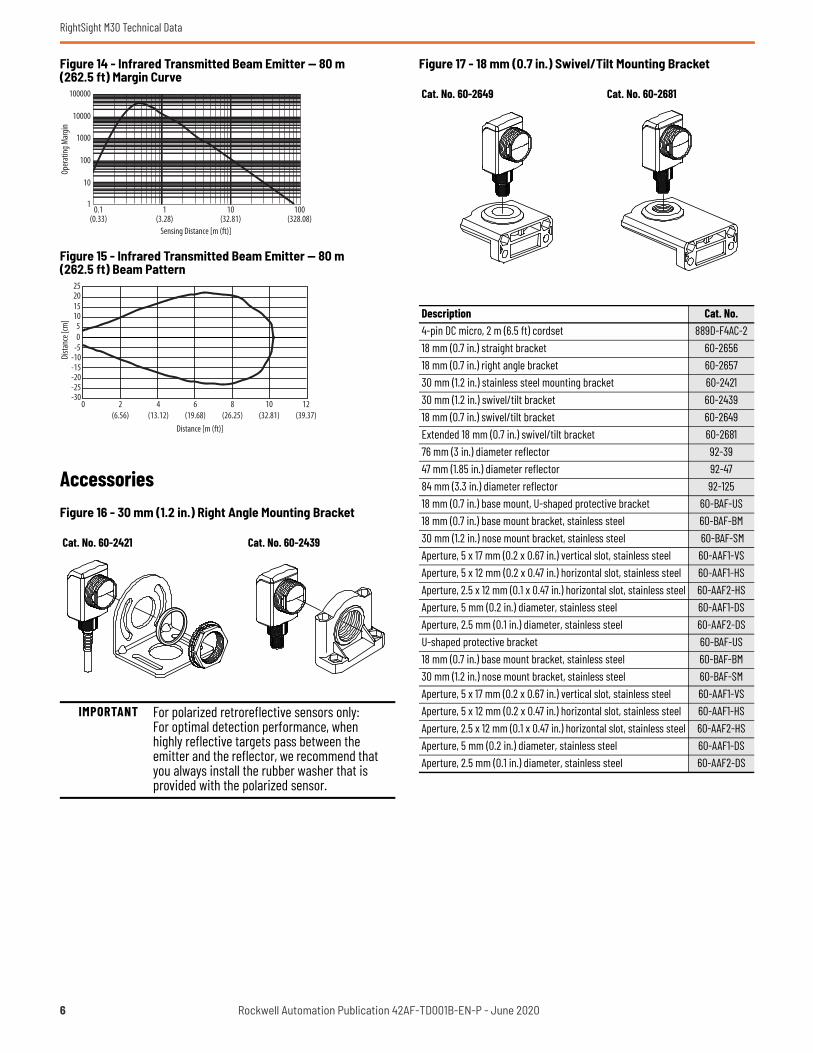
Figure 14 - Infrared Transmitted Beam Emitter — 80 m (262.5 ft) Margin Curve
Figure 15 - Infrared Transmitted Beam Emitter — 80 m (262.5 ft) Beam Pattern
AccessoriesFigure 16 - 30 mm (1.2 in.) Right Angle Mounting Bracket
Figure 17 - 18 mm (0.7 in.) Swivel/Tilt Mounting Bracket
Cat. No. 60-2421 Cat. No. 60-2439
IMPORTANT For polarized retroreflective sensors only: For optimal detection performance, when highly reflective targets pass between the emitter and the reflector, we recommend that you always install the rubber washer that is provided with the polarized sensor.
100000
10000
1
10
100
1000
0.1(0.33)
1(3.28)
10(32.81)
100(328.08)
Sensing Distance [m (ft)]
Oper
ating
Mar
gin
25201510
50
-5-10-15-20-25-30
0 4(13.12)
6(19.68)
8(26.25)
10(32.81)
12(39.37)
Distance [m (ft)]
Dista
nce [
cm]
2(6.56)
Cat. No. 60-2649 Cat. No. 60-2681
Description Cat. No.4-pin DC micro, 2 m (6.5 ft) cordset 889D-F4AC-218 mm (0.7 in.) straight bracket 60-265618 mm (0.7 in.) right angle bracket 60-265730 mm (1.2 in.) stainless steel mounting bracket 60-242130 mm (1.2 in.) swivel/tilt bracket 60-243918 mm (0.7 in.) swivel/tilt bracket 60-2649Extended 18 mm (0.7 in.) swivel/tilt bracket 60-268176 mm (3 in.) diameter reflector 92-3947 mm (1.85 in.) diameter reflector 92-4784 mm (3.3 in.) diameter reflector 92-12518 mm (0.7 in.) base mount, U-shaped protective bracket 60-BAF-US18 mm (0.7 in.) base mount bracket, stainless steel 60-BAF-BM30 mm (1.2 in.) nose mount bracket, stainless steel 60-BAF-SMAperture, 5 x 17 mm (0.2 x 0.67 in.) vertical slot, stainless steel 60-AAF1-VSAperture, 5 x 12 mm (0.2 x 0.47 in.) horizontal slot, stainless steel 60-AAF1-HSAperture, 2.5 x 12 mm (0.1 x 0.47 in.) horizontal slot, stainless steel 60-AAF2-HSAperture, 5 mm (0.2 in.) diameter, stainless steel 60-AAF1-DSAperture, 2.5 mm (0.1 in.) diameter, stainless steel 60-AAF2-DSU-shaped protective bracket 60-BAF-US18 mm (0.7 in.) base mount bracket, stainless steel 60-BAF-BM30 mm (1.2 in.) nose mount bracket, stainless steel 60-BAF-SMAperture, 5 x 17 mm (0.2 x 0.67 in.) vertical slot, stainless steel 60-AAF1-VSAperture, 5 x 12 mm (0.2 x 0.47 in.) horizontal slot, stainless steel 60-AAF1-HSAperture, 2.5 x 12 mm (0.1 x 0.47 in.) horizontal slot, stainless steel 60-AAF2-HSAperture, 5 mm (0.2 in.) diameter, stainless steel 60-AAF1-DSAperture, 2.5 mm (0.1 in.) diameter, stainless steel 60-AAF2-DS
6 Rockwell Automation Publication 42AF-TD001B-EN-P - June 2020

RightSight M30 Technical Data
Figure 18 - Apertures
Figure 19 - Cat. No. 60-BAF-US 18 mm (0.7 in.) Mounting Bracket
Figure 20 - Cat. No. 60-BAF-SM 30 mm (1.2 in.) Bracket Side
Figure 21 - Cat. No. 60-BAF-BM 18 mm (0.7 in.) Bracket Back
Cat. No. 60-AAF1-VS5x17 mm (0.2x0.67 in.)
Vertical Slot
Cat. No. 60-AAF1-HS5x12 mm (0.2x0.47 in.)
Horizontal Slot
Cat. No. 60-AAF2-HS2.5x12 mm (0.1x0.47 in.)
Horizontal Slot
Cat. No. 60-AAF1-DS5 mm (0.2 in.)
Diameter
Cat. No. 60-AAF2-DS2.5 mm (0.1 in.)
Diameter
4X R 0.41(0.016)
5.08(0.20)
19.05(0.75)
4X R 0.406(0.016)
5.08(0.20)
11.938(0.47) 4X R 0.406
(0.016)
2.54(0.10)
11.938(0.47)
5.08(0.20) Ø
2.54(0.10) Ø
6.98(0.27)
13.98 (0.55)
4 x R 4.57 (0.18)
X
Section x - x
4 x Ø 4.50(0.18)
4 x 1.84(0.07)
4 x 82°
2 X 55.88 (2.2)
90°
3.17 (0.12) Ref
37.95(1.49)
13.97 (0.55)
22.15(0.87)
Ø 18.49 (0.73)27.94 (1.10)
4 x Ø 9.52 (0.37)
2 x 8.43(0.33)
2 x 33.02(1.30)
x
2 x R 2.29(0.09)
90°
12.7 (0.50)
33.02 (1.30)
6.98(0.27)
2 x 1.84 (0.07)9.73(0.38)
2 x Ø 4.5 (0.18)
12.7(0.50)
4 x 4.57(0.18)
6.35(0.25)
22.2(0.87)
22.86 (0.90)
Ø 30.15 (1.19)
3.17(0.12) Ref
19.05 (0.75)
44.45 ± 0.25(1.75 ± 0.01)
0.79(0.03) Ref
90°
2 x 82°
R 2.29(0.09)
2 x 0.77 (0.03)
45.72 (1.80)
2 x Ø 3.83 (0.15)2 x 1.75 (0.06)
17.78(0.70) 30.48 (1.20)
3.17(0.12) Ref
2 x 0.79(0.31)
15.16(0.60)
90°
2 x 82°
R 2.29(0.09)
Ø 18.49(0.73)
8.89 (0.35)
9.27 (0.36)
6.98(0.27)
8.25(0.32)
8.89(0.35)
19.05 (0.75)4 x R
4.57 (0.18)
35.56 (1.40)
30.48(1.20)
0.79(0.03) Ref
Rockwell Automation Publication 42AF-TD001B-EN-P - June 2020 7

Publication 42AF-TD001B-EN-P - June 2020Supersedes Publication 42AF-TD001A-EN-P - January 2019 Copyright © 2020 Rockwell Automation, Inc. All rights reserved. Printed in the U.S.A.
Rockwell Automation Support
Use these resources to access support information.
Documentation Feedback
Your comments help us serve your documentation needs better. If you have any suggestions on how to improve our content, complete the form at rok.auto/docfeedback.
Waste Electrical and Electronic Equipment (WEEE)
Technical Support Center Find help with how-to videos, FAQs, chat, user forums, and product notification updates. rok.auto/support
Knowledgebase Access Knowledgebase articles. rok.auto/knowledgebase
Local Technical Support Phone Numbers Locate the telephone number for your country. rok.auto/phonesupport
Literature Library Find installation instructions, manuals, brochures, and technical data publications. rok.auto/literature
Product Compatibility and Download Center (PCDC)
Get help determining how products interact, check features and capabilities, and find associated firmware. rok.auto/pcdc
At the end of life, this equipment should be collected separately from any unsorted municipal waste.
Rockwell Automation maintains current product environmental information on its website at rok.auto/pec.
Allen-Bradley, ArmorBlock, expanding human possibility, ProposalWorks, RightSight, Rockwell Automation, and Rockwell Software are trademarks of Rockwell Automation, Inc.Trademarks not belonging to Rockwell Automation are property of their respective companies.
Rockwell Otomasyon Ticaret A.Ş. Kar Plaza İş Merkezi E Blok Kat:6 34752, İçerenkÖy, İstanbul, Tel: +90 (216) 5698400 EEE YÖnetmeliğine Uygundur