Embed Size (px)
Citation preview

Rig: A simple, secure and flexible design forPassword Hashing
Donghoon Chang, Arpan Jati, Sweta Mishra, Somitra Kumar Sanadhya
Indraprastha Institute of Information Technology, Delhi (IIIT-D), India{donghoon,arpanj,swetam,somitra}@iiitd.ac.in
Abstract. Password Hashing, a technique commonly implementedby a server to protect passwords of clients, by performing a one-waytransformation on the password, turning it into another string called thehashed password. In this paper, we introduce a secure password hashingframework Rig which is based on secure cryptographic hash functions.It provides the flexibility to choose different functions for differentphases of the construction. The design of the scheme is very simpleto implement in software and is flexible as the memory parameter isindependent of time parameter (no actual time and memory trade-off)and is strictly sequential (difficult to parallelize) with comparativelyhuge memory consumption that provides strong resistance againstattackers using multiple processing units. It supports client-independentupdates, i.e., the server can increase the security parameters byupdating the existing password hashes without knowing the password.Rig can also support the server relief protocol where the client bears themaximum effort to compute the password hash, while there is minimaleffort at the server side. We analyze Rig and show that our proposalprovides an exponential time complexity against the low-memory attack.
Keywords: Password, Password hashing, GPU attack, Cache-timingattack, Client-independent update, Server-relief technique
1 Introduction
A password is a secret word or string of characters which is used by a principalto prove her identity as an authentic user to gain access to a resource. Beingsecret, passwords cannot be revealed to other users of the same system. In orderto ensure the confidentiality of the passwords even when the authenticationdata is somehow leaked from the server, passwords are never stored in clear,but transformed into an illegible form and then stored. Specifically, ‘PasswordHashing’ is the technique which performs a one-way transformation on apassword and turns it into another string, called the ‘hashed’ password. Strongpassword protection, i.e., a technique of password hashing that makes bruteforce attack on password guessing infeasible, either in software or by using GPUs(Graphics Processing Unit), is essential to protect the user security and identity.Thus any working password hashing scheme should be resistant to brute forceattack.

Password hashing is an active topic of interest in cryptography communityand a competition on password hashing is going on [1]. Currently, thesignificant constructions for password hashing are PBKDF2 [12], Bcrypt [14]and Scrypt [13]. All of these do not satisfy most of the necessary requirementsmentioned at the competition page [1]. PBKDF2 (NIST standard) consumes veryless memory as it was mainly designed to derive keys from a seed (password).Bcrypt uses fixed memory (4KB) for its implementation. Scrypt is not simple(different internal modules) and not flexible (time and memory parameters aredependent) and susceptible to cache timing attack ( discussed in section 5 ).
Specifically, the rate at which an attacker can guess passwords is a keyfactor in determining the strength of the password hashing scheme. Currentrequirements [1] for a secure password hashing scheme are the following:
– The construction should be slow to resist password guessing attack butshould have a fast response time to prove the authenticity of the user.
– It should have a simple design and should be easy to implement (coding,testing, debugging, integration), i.e., the algorithm should be simple in thesense of clarity and concise with less number of internal components andprimitives.
– It should be flexible and scalable, i.e., if memory and time are not dependentthen one would be able to scale any of the parameters to get requiredperformance.
– Cryptographic security [1]: The construction should behave as a randomfunction (random-looking output, one-way, collision resistant, immune tolength extension, etc.).
– Resistant to GPU attack: A typical GPU has lots of processing cores buthas limited amount of memory for each single core. It is quite efficient foran attacker to utilize all the available processing cores with limited memoryto run brute-force attack over the password choices. Use of comparativelyhuge memory per password hash by the password hashing constructioncan restrict the use of GPU. Therefore, the design should have largememory consumption to force comparatively slow and costly hardwareimplementation that can resist the GPU attack.
– Leakage Resilience: The construction should protect against informationextraction from physical implementation, i.e., the scheme should not leakinformation about the password due to cache timing or memory leakage,while supporting any length of password.
– The construction should have the ability to transform an existing hash toa different cost setting (client independent update, explained in section 5)without knowledge of the password.
– It is good if the construction provides server relief technique where the clientperforms most of the computations for password hashing and the server putsminimal effort with minimal use of resources, to reduce the load of the server.This property needs a secure protocol to maintain the security of the hashcomputation (discussed in section 5).

The most challenging threat faced by any password hashing scheme is theexistence of cheap, massively parallel hardware such as Graphics ProcessingUnits (GPUs), Application-Specific Integrated Circuits (ASICs) and Field-Programmable Gate Arrays (FPGAs). Using such efficient hardware, anadversary with multiple computing units can easily try multiple differentpasswords in parallel. To prevent such attempts we need to slow down passwordhash computation and ensure that there is little parallelism in the design. Oneway to achieve this is to use a ‘Sequential memory-hard’ algorithm, a term firstintroduced with the design of ‘Scrypt’ [13], a password hashing scheme. The maindesign principle of Scrypt is that it asymptotically uses almost as many memorylocations as it uses operations to slow down the password-hash computation.Memory is relatively expensive, so, a typical GPU or other cheap massively-parallel hardware with lots of cores can only have a limited amount of memoryfor each single core. Hence an attacker with access to such hardware will still notbe able to utilize all the available processing cores due to the lack of sufficientmemory and will be forced to have an (almost) sequential implementation of thepassword hashing scheme.
In this document we propose Rig, a password hashing scheme which aimsto address the above mentioned requirements. Rig is based on cryptographic(secure) hash functions and is very simple to implement in software. It isflexible as the memory parameter is independent of time parameter (no actualtime and memory trade-off) and is strictly sequential (difficult to parallelize)with comparatively huge memory consumption that provides strong resistanceagainst attackers using multiple processing units. It supports client-independentpassword hash up-gradation without the need of the actual password. Thisfeature helps the server to increase the security parameters to calculate thepassword hash to reduce the constant threats of technological improvements,specifically in the field of hardware. Rig provides protection against theextraction of information from cache-timing attack and prevents denial-of-service attack if implemented to provide server-relief technique. We analyze Rigand show that our proposal provides an exponential time complexity againstmemory-free attack. It gives the flexibility to choose different functions fordifferent phases of the construction and we denote the general construction ofRig as Rig [H1, H2, H3]. In this work we provide two variants of Rig [H1, H2,H3]. A strictly sequential variant, Rig [Blake2b, BlakeCompress, Blake2b] andthe other variant, Rig [BlakeExpand, BlakePerm, Blake2b] which improves theperformance by performing memory operations in larger chunks.
The rest of the document is organised as follows. In section 2 we presentthe important preliminaries necessary for understanding the specification. Thisis followed by the introduction of significant hardwares used as attack platformin section 3. The specification and design rationale of the scheme are presentedin sections 4 and 5 respectively. Subsequently, the implementation aspects andperformance analysis are presented in sections 6 and 7. Finally, in sections 8and 9, we provide the security analysis of the scheme and the conclusions of thepaper respectively.

2 Preliminaries
The techniques used in our construction are discussed below.
– Binary 64-bit mapping: It is a 64-bit binary representation of the decimalvalue. The binary number
an−12n−1 + an−22n−2 + · · ·+ a0
is denoted as an−1an−2 · · · a0 where ai ∈ {0, 1} and n is the number of digitsto the left of the binary (radix) point. In our construction we use n = 64and we denote binary64(x) for 64-bit binary representation of the value x.
– Bit reversal permutation [9,11] (br): It is implemented to permute theindices of an array of n = 2k elements where k ∈ N. We explain the steps ofthe permutation through Algoritm 1 below.The example of a bit reversal permutation applied on an array of m = 23
elements where k = 3 and indices are 0, 1, · · · , 7 is given below.br[000, 001, 010, 011, 100, 101, 110, 111] = [000, 100, 010, 110, 001, 101, 011, 111]= br[0], br[1], br[2], br[3], · · · , br[7].
Algorithm 1: Bit reversal permutation (br)
Input: Indices of an array A of n = 2k elements where k ∈ N andindices are: 0, 1, 2, · · · , n− 1.
Output: Permuted indices of array A as: br[0], br[1], br[2], · · · , br[n− 1]1. for i = 0 to n− 1
2. (i)bink = ik−1ik−2 · · · i1i0 =∑k−1
j=0 2jij3. . (i)bink = k-bit binary representation of value i
4. br[i] =∑k−1
j=0 2jik−1−j
5. return br[0], br[1], br[2], · · · , br[n− 1]
3 Attack platforms: Significant hardwares
According to Moore’s Law [15], the number of transistors on integrated circuitsdoubles approximately every two years. This has indeed been the case over thehistory of computing hardware. Following this law, hardware is becoming moreand more powerful with time. This happens to be the most prominent threatfor existing password hashing schemes. Consequently, there is a need to raisethe cost of brute force attack by controlling the performance of the massivelyparallel hardware available.
An important electronic circuit, Graphics Processing Unit (GPU), andtheir highly parallel structure makes them more effective than general-purposeCPUs for algorithms where processing of large blocks of data is done in parallel.An Application-Specific Integrated Circuit (ASIC), is an integrated circuit(IC) which can be customized with memory chips to implement a dedicateddesign. An ASIC can not be altered after final design hence the designers needto be certain of their design when it is implemented in ASIC. On the other hand,

Field Programmable Gate Arrays (FPGAs) are programmable integratedcircuits and consist of an array of logic elements together with an interconnectednetwork and memory chips, providing high-performance. A designer can test herdesign on an FPGA before implementing it on an ASIC.
Both ASIC and FPGAs can be configured to perform password hashing withhighly optimized performance. The cost of implementation on FPGA is cheaperthan ASICs if the number of units of the hardware required is small. Therefore,one can easily use parallel FPGAs to increase the rate of password guessing.RIVYERA FPGA cluster is an example of a very powerful and cost optimizedhardware. It can hash 3,56,352 passwords per second by using PBKDF2 (NISTstandard, Password Based Key Derivation Function 2) with SHA-512 and 512-bitderived key length [8]. This high performance is possible on the FPGA becausePBKDF2 does not consume high memory for password hashing. ComparingFPGAs with GPUs (Graphics processing units), the authors of [8] provide resultsof the same implementation on 4 Tesla C2070 GPUs as 1,05,351 passwords persecond. ASIC is better than FPGA purely on performance in terms of numberof hashes per second. However, FPGA is preferable when cost is considered withthe speed of hashing. Following Moore’s law, the speed of hardware is likely toincrease by almost a factor of two in less than two years. However, as processorspeeds continue to outpace memory speeds [10], the gap between processor andmemory performance increases by about 50 % per year [5]. Thus, there is aneed to minimize the effects of such high performance hardware. Hence, we needa password hashing algorithm which consumes comparatively large memory toprevent parallel implementation.
4 Specification
Our construction is described in Fig. 1. Following is the step-by-step descriptionof Algorithm 2 which explains our construction Rig.
1. First we need to fix the following parameters:– pwd = The user password of any length.– s = The salt value of any length.– n= The number of iterations required to perform iterative
transformation phase.– mc= The memory count from which the memory-cost is defined as: m =
2mc , i.e., m denotes the number of items to be stored in the memory.The value of m is updated as: mi+1 = 2×mi at each round.
– r= The number of rounds for the setup phase followed by iterativetransformation phase and output generation phase.
– l= The output length of the password hash.– t= The number of bits retained from hash output after truncation. Used
with a function trunct(x) = x� (|x| − t), where x is the hash output.2. Initialization phase: We map the parameters, namely the values: password
length pwdl, salt length sl, n and the output length, l to a 64-bit binary valueusing binary64 mapping. We create the value x as the concatenation (||) ofthe above mentioned parameters as
x = pwd ‖ binary64(pwdl) ‖ s ‖ binary64(sl) ‖ binary64(n) ‖ binary64(l)

H2 H2
H2H2
H3 h∗
1 2
(m+ 1) (m+ 2)
k[1]
H2H2
(2m+ 1) (2m+ 2)
H2H2 H2
(nm+ 1) (nm+ 2) (n+ 1)m
k[0] k[m-1]
((n+ 1)m+ 1)
∗Note: :Shows first t−bit truncation and value depends on implementation.k[br[i]] : is the ith index of array k obtained from bit reversal permutation
k[2]
α
t t t th0
t t t t
tt t t
t t t t
t
i=1
i=2
i= n
s||m
a[0] a[1] a[m-1]
a[0] a[1]
a[0]
a[0]
a[1]
a[1] a[m-1]
H2
H2a[m-1]
H2a[m-1]
m
2m
3m
H2H2
H2
H2
H2
Initialization phase:
Iterative Transformationphase:
SetupPhase:
Output generation phase:output of each round
α α
k[br[0]] k[br[1]] k[br[2]]k[br[m− 1]]
k[br[m− 1]]
k[br[m− 1]]
k[br[2]]
k[br[2]]
k[br[0]]
k[br[0]]
k[br[1]]
k[br[1]]
H2
H1x αH1
for round= 1, m = 2mc
k[0] k[1]
k[1]k[0]
k[2]
k[2]
k[m-1]
k[m-1]
x = pwd ‖ binary64(pwdl) ‖ s ‖ binary64(sl) ‖ binary64(n) ‖ binary64(l)
Fig. 1: Graphical representation of the proposed construction.

Rig: A password hashing schemeAlgorithm 2: Rig [H1, H2, H3] Construction
Input: Password (pwd), Password length (pwdl), Salt (s), Salt length (sl), No. of iterations (n),Memory count (mc), No. of bits to be retained from hash output of the setup phase (t),Output length (l), No. of rounds (r).
Output: l-bit hash value hr∗ obtained after r rounds
1. . Initialization phase: generates α from password2. Initialize: a random salt (s) of atleast 16-bytes, number of iterations (n),
value of memory count mc where m = 2mc , value t3. x = pwd ‖ binary64(pwdl) ‖ s ‖ binary64(sl) ‖ binary64(n) ‖ binary64(l) . concatenation: ‖4. α = H1(x) . H1 : underlying hash function5. for round 1 to r6. . Initialization of Setup phase: Creates two arrays k and a
where |k| = |a| = m where m = 2(round−1) × 2mc
7. h0 = initialized with the value of π after decimal, and |h0| = |α|.8. a[0] = α⊕ h0, k[0] = trunct(h0)9. for i = 1 to m
10. hi = H2(i ‖ a[i− 1] ‖ k[i− 1]) . H2 : underlying hash function11. if i 6= m12. a[i] = α⊕ hi
13. k[i] = trunct(hi) . retains the first t−bits of the hash output14. . Initialization of Iterative Transformation phase15. for i = 1 to n16. for j = 1 to m17. a[j − 1] = a[j − 1]⊕ h{im+j−1}18. br[j − 1] = index value of array k obtained using
bit reversal permutation19. . initialize a temporary array |ktemp| = |k|20. ktemp[j − 1] = k[br[j − 1]]⊕ trunct(him+j−1)
21. him+j = H2((im+ j) ‖ a[j − 1] ‖ ktemp[j − 1])
22. k = ktemp23. . Output generation phase24. hround
∗ = (H3((n+ 1)m+ 1) ‖ h(n+1)m ‖ s ‖ binary64(m))25. if round < r26. α = hround
∗
and compute H1(x) = α where H1 is the underlying hash function. We useα for further calculations in the setup phase.
3. Setup phase We initialize h0 with the value of π after the decimal point.We take as many digits of π as desired to ensure that |h0| = |α|. The valuesh0 and α are used to initialize two arrays k and a and further m− 1 valuesof the arrays are iteratively calculated as shown in the fig. 1. First t-bits ofeach hash output are stored in the array k.
The large number of calls to the underlying hash function are guaranteed tohave different inputs by the use of different counter values. H2 denotes theunderlying hash function.
4. Iterative transformation phase This phase is designed to make constantuse of the stored array values and to update them. Here we modify each

element of the arrays a and k, n-times where n is the number of iterations.Array a is accessed sequentially where values of array k are accessed usingbit reversal permutation explained in Algorithm 1. We denote the index ofarray k obtained applying bit-reversal permutation as: br[j], 0 ≤ j ≤ m− 1.
5. Output generation phase After execution of the setup phase and iterativetransformation phase sequentially, we calculate one more hash, denoted byH3 to get the output of each round. If round=1, this output is consideredas the password hash.Note: The output is an l-bit value. The algorithm stores the output as thehashed password. Our construction allows for storing a truncated portion ofthe hash output as well. If this is desired we can take one of the followingtwo approaches.(a) The user may run the complete algorithm as described above and
truncate the final output after r rounds to the desired length. Thisapproach does not support client-independent update.
(b) To support client-independent updates the user can choose a length fortruncation which is sufficient to claim brute-force security. Then appendsome constant value, we suggest the hexadecimal value of π after first64-bytes of decimal point. Take as many digits as desired to make theoutput length of each round equal to the length of α of the setup phase.So this way one can reduce the storage requirement for password hashesat the server.
5 Design rationale
Existing password hashing schemes are not simple and do not fulfill the necessaryrequirements as discussed in section 1. We have tried to design a solutionwhich overcomes the known disadvantages of existing schemes (PBKDF2 [12],Bcrypt [14] and Scrypt [13]). The primary concerns against existing proposalsare their complex design and their inefficiency to prevent hardware threats. Wehave tried to strengthen our design by considering the necessary requirementsas mentioned in section 1.
1. Initialization phase We have used concatenation of password, salt, 64-bitvalue of pwdl, sl, n and l as input to increase the size of input. This resistsbrute force dictionary attack.
2. Setup phase In this phase we initialize h0 with π, as we want to have arandom sequence and π is not known to have any pattern in the sequenceof digits after the decimal point. We generate the values that are requiredto be stored and repeatedly accessed throughout the remaining phases. Thisensures that a large memory requirement criteria for a password hashingscheme is satisfied which neutralizes the threat of using recent technologicaltrends, such as GPUs, ASICs etc. We use different counter values for eachhash computation to make all hash inputs different. This reduces collisionsand hence makes the output different.

For array k there is a flexibility to vary the bit storage by taking first t-bitsof the hash output where t is taken to be close to the hash-length but notequal to the hash-length. This fulfills the demand of huge memory while atthe same time ensures sequential hash calculation and forces an attacker tocompute the hash at run-time thus slowing him down. Further, it also allowsto extend the scope of implementation in that a low memory device maykeep very few bits of the hash values stored but may increase the number ofiterations. This ensures that Rig can be implemented in resource constraineddevices.
3. Iterative transformation phase To make the storage requirementcompulsary, this phase progresses sequentially, accessing and updating allstored values at each iteration. Here again, we use different counters for hashinput for the same reason as mentioned above. In this phase the memoryaccess pattern is made password independent to reduce the chance of cachetiming attack which we have explained later in this section.
4. Output generation phase This is the last phase of each round. We reusethe salt value as input to make the collision attack difficult.Apart from that the output of each round can be truncated to a desiredlength. This is optionally mentioned to handle the situations when it isrequired to reduce the server storage per password.
The other important criteria taken into account in the design of the scheme arethe following:
5. Simplicity and flexibility Symmetry (as setup phase and iterativetransformation phase follows similar structure) in the design of Rig enhancesthe overall clarity of the scheme. An earlier password hashing schemeScrypt [13] uses PBKDF2 (internally calls HMAC-SHA256) and ROMix(internally calls BlockMix and uses Salsa20/8). Unlike Scrypt, Rig uses onlya single primitive (a cryptographically secure hash function). This makesour scheme easier to understand and easy to implement (coding, testing,debugging and integration).In our scheme the memory parameter is independent of the time parameter.This flexibility in design choice allows a user to scale any of these parametersto get the required performance. On the other hand we have the flexibility forthe choice of the functions H1, H2 and H3 (see Fig. 1), but proper selectionof the primitives are required to maintain the overall design properties andsecurity. Therefore there can be multiple variants of Rig aimed at differentimplementations or scenarios.
6. Random output Our scheme calls a hash function repeatedly. We usedifferent counters for each of these hash calls to ensure that no input to thehash function is repeated. The security of Rig relies on the prevention ofpreimage and collision attacks against the underlying hash function. Use ofany state-of-the-art hash function (e.g. any finalist of SHA-3 competition)ensures the security of our scheme. We use Blake2b [3] in demonstratingthe performance of our scheme later in this paper, although any other hashfunction could easily be used instead.

With the property of different input, different output and same input,same output, our scheme mimics the Random Oracle Model. This providestheoretical justification of the security of Rig.
7. Client-independent update [9] Our design supports client independentupdate, i.e., server can increase the security parameter without knowing thepassword. This is possible if we fix the value of n (number of iterations) andincrease the number of rounds r. Each round of the algorithm doubles thememory consumption m from the previous round and hence increases thesecurity parameter. This is possible because the output of each round canbe treated as the value α at the next round and then can easily follow theAlgorithm 2 to produce the output of the next round. The idea of clientindependent update of the security parameter m is fulfilled by the followingway. The value of m is updated at each next round i + 1 (say) from itsprevious round i as: mi+1 = 2×mi.The overall procedure is: output of each round is the input to the next.Each round gives full hash maintaining all requirements of a good passwordhashing technique. By increasing the number of rounds, the scheme increasesthe required memory and time hence increases the security parameterwithout the interference of the client.
8. Resistance against cache-timing attack In our construction, to accessthe memory which is stored in an array k, we use bit-reversal permutation,which is independent of the password used. If a password dependentpermutation is used and if the array can be stored in the cache whileaccessing the values, an attacker can trace the access pattern observing thetime difference in each access of the array index. This helps the adversaryto filter the passwords that follows similar memory access pattern and tomake a list of feasible passwords. Therefore, a password hashing schemeshould have password-independent memory access patterns and to followthis requirement we use bit reversal permutation as in [9].
9. Server-relief hashing Current requirement of a password hashingtechnique is that it should be slow and should demand comparatively largememory to implement. But this requirement may put extra load on server.Therefore we need a protocol to divide the load between the client and theserver. The idea is provided in [9] and our construction supports this propertyfollowing the protocol as mentioned below:First the authentication server provides the salt to the client. The clientperforms the initialization phase, setup phase and iterative transformationphase (see Algorithm 2), and sends the end result to the server. The servercomputes the output generation phase and produces the final hash. This waywe can easily reduce the load of the server.Note: In this case, an attacker acting as a client, can repeatedly send somerandom data without following the computations of the proposed algorithmto the server. Here, the attacker can easily get the access with a correctguess. But, the complexity of the random guess will be equivalent to thebrute-force complexity i.e. 2n, where n is the output length of the underlyinghash function. Therefore this can not be a feasible attack.

6 Implementation aspects
This proposed construction for password hashing can be implemented efficientlyon a wide range of processors. However, the same implementation will requirehuge number of computations if dedicated hardware such as ASIC or FPGA isused with limited memory.
Our design allows the flexibility to utilize less storage with increased numberof calculations if we retain few bits of the intermediate hash computation aftertruncation and increase the number of iterations n. This way, Rig can be efficienton low memory devices.
We designed Rig to have a highly flexible structure. By changing the functionsH1, H2 and H3 (see Figure 1) we can completely change the overall designproperties. From side channel resistance to GPU or ASIC/FPGA resistance,any property can be achieved by the proper selection of the above primitives.Therefore there can be multiple variants aimed at different implementationsor scenarios. As mentioned before, we describe the general construction of Rigas Rig [H1,H2,H3], where we can design/choose the functions H1, H2, H3 forimplementing different variants of Rig.We have designed and implemented two versions of Rig as follows:
1. Rig [Blake2b, BlakeCompress, Blake2b] This variant is strictlysequential. Full Blake2b is used for H1 and H3 while the first roundof the compression function of Blake2b is used for H2 (and we call itBlakeCompress). We have removed the constants in the ‘G’ function ofBlake2b as suggested by the Blake authors in [3] to improve the overallperformance. This version does a large number of random reads and writesand as a result it is strictly bounded by memory latency.
2. Rig [BlakeExpand, BlakePerm, Blake2b] This variant is designed toimprove the performance by performing memory operations in larger chunks.The functions H1 and H2 are parallelized internally and the idea of handlinglarger chunk size improves the performance significantly without changingthe overall sequential nature and memory-hardness of Rig. It also makesthis variant of Rig much more difficult to execute efficiently in GPUs andFPGA/ASIC (explained in sections 6.4 and 6.5). We implemented thefunctions H1 as ‘BlakeExpand’ and H2 as ‘BlakePerm’. These functions areexplained later. The function H3 uses full Blake2b.
6.1 Design of Rig [Blake2b, BlakeCompress, Blake2b]
This strictly sequential variant follows the general construction of Rig asexplained in section 4. The functions H1 and H3 implements Blake2b (fullhash). The function H2 is implemented using first round of Blake2b compressionfunction.
6.1.1 Design of the BlakeCompress function In Figure 2 we graphicallyshow the implementation of H2 as BlakeCompress. H2 takes 1024 bits input and

initializes the initial state of Blake2b with this input. Then the eight G-functionsas defined in Blake2b are applied with an all zero input message of length 1024bits. RFi denotes the ith call to these eight G-functions. As we use the first roundonly, we show the round as RF1 in Figure 2. The modified state after RF1 isthen split in two equal halves and xor’ed together to produce 512-bits of output.This choice of implementation is different from the actual Blake2b in many ways.The actual Blake2b construction, shown in Figure 3, has an initialization phasewhich initializes the starting state. A permutation of the message mi is suppliedas the input to each RFi for round i = 1 to 12. After 12 rounds, the finalizationphase performs feedforward xor’ing with output of RF12. This preserves theonewayness of the Blake2b function. This feedforward xor’ing is omitted in ourBlakeCompress implementation. This choice of implementation reduces the timeof hash computation and improves the performance. The overall security is notcompromised by this implementation (see section 8.2.1).
RF1
512 bits
512 bits
message (0)
BlakeCompress
x 512 bits1024 bits
y
Fig. 2: Function H2 implemented as function BlakeCompress[x] = y, where inputlength of x= 1024 bits and output length of y = 512 bits. RF1 is the first roundof Blake2b compression function. Input size of RF1 = 1024 bits.
6.2 Design of Rig [BlakeExpand, BlakePerm, Blake2b]
The optimized variant of Rig uses an expansion function BlakeExpand to expandthe state and a compression function BlakePerm to compress the state. FullBlake2b is used to hash the output state after the iterative-transformation phaseto obtain the final hash. The design aspects are described below.

RF1
round-1 round-2 round-12
Finalization
Feedforward xor’ing
li
IV
RF2 RF12hi
message block: mi (1024 bits)
Blake2b(hi,mi, li) = hi+1
512 bitshi+1I
Blake2b compression funtion defined as Blake2b(hi,mi, li)= hi+1 where• hi is the 512 bits chaining value,• mi is the ith message block and each mi is of length1024 bits• li denotes the number of data bytes in m0,m1, · · · ,mi
• I denotes the initialization phase of Blake2b• RFi denotes the ith call to the eight G-functions
Fig. 3: Blake2b compression function
6.2.1 Design of the BlakeExpand expansion function The BlakeExpandfunction is a very simple function which expands the input x to a fixed size of8KiB. The function BlakeExpand is an instantiation of H1. The input x passesthrough 128 individual instances of Blake2b (full hash) each appended by acounter as xi = x ‖ i, for 0 ≤ i ≤ 127 and produces the output α = α0 ‖ α1 ‖· · · ‖ α127 where each αi is of length 512 bits, i.e., 64 bytes. This constructionensures that the output of the function is random and the randomness dependssolely on the cryptographic strength of Blake2b. Since this function needs to beexecuted only once, it has negligible impact on the performance of the overallRig construction.
6.2.2 Design of BlakePerm function We provide the design considerationsfor the function BlakePerm before the description of the design.
Design considerations for BlakePerm function The DRAM memorylatency is the limiting factor for the entire design of Rig. Initialization andcopying data takes over 70 percent of the total run-time. In order to improvethe overall performance one trivial optimization would be to increase the size ofchunks in which the read and write operations are performed. The latest highperformance processor offerings from Intel and AMD influenced many of thedesign decisions as they would be the most common target platform. There areseveral design considerations like:

α0
α1
x0Blake2b
Blake2b
Blake2b
‖
‖
‖
x1x
0
1
127
‖
‖
‖
α
α127x127
BlakeExpand [x] = α where α = α0 ‖ α1 ‖ · · · ‖ α127, xi = (x ‖ i) for 0 ≤ i ≤ 127
and x = pwd ‖ binary64(pwdl) ‖ s ‖ binary64(sl) ‖ binary64(n) ‖ binary64(l)
Fig. 4: Function BlakeExpand
– L1 cache size This is one of the major factors because the L1 cache has thelowest latency of around 1-1.5ns (as few as 3 clocks). Therefore it is importantthat the work piece (chunk) fits within this size for high performance in caseof a compute intensive task.
– L1/L2/L3 cache line size A typical modern processor has cache linesize of 64 bytes. Therefore working in multiple of 64 bytes with preferablyaligned memory access is the best strategy. The problem with workingwith other non-multiple sizes is that there would be a lot of extra accessesand split loads and stores, which will dramatically reduce performance incomputation intensive tasks. The Blake2b compression function nicely fitsthis requirement as it compresses 128 bytes to 64 bytes. The only otherrequirement is an implementation detail for setting the proper alignedmemory access while memory allocation. As a result, in our implementationwe have zero split load/stores.
– DRAM Latency The memory latency is the primary limiting factor inalgorithms having random reads and writes. DRAM generally has latencyvalues of 250+ clock cycles. One strategy to get around this problem would
be to perform reads and writes in larger chunks. If the chunk size is largeenough, the performance hit due to latency can become significantly small.We tested against various sizes from 2 KiB to 64 KiB and observed that 16KiB is a good size; and it also fits the L1 cache. We have, as a result chosenchunk size of 16 KiB for the H2 function.
Design of the BlakePerm function The BlakePerm function is acompression function which compresses 16 KiB of data to 8 KiB. It is a twostep function as described below.
i
g′1
g′127
g′0
i. Compression ii. Permutation
g1
g127
g
Permutation
BlakePerm [S] =g, where input S = s0 ‖ s1 ‖ · · · ‖ s127 and output g = g0 ‖ g1 ‖ · · · ‖ g12716 KiB input is equally divided in each 128 byte si.RF1 denotes the first round of Blake2b compression function
g′0
g′1
01
15
512
I J
78
Index- i
g′127
g0
1023
1016
01
15
512
78
8Bytes
Index- j
j = (i× 109+ 512)%10240 ≤ i, j ≤ 1023
8Bytes
g′
512 bitss0
1024 bits
0
512 bitss1
1024 bits
0
512 bits1024 bits
0
s127
RF1
RF1
RF1
BlakePerm[S] = g
Fig. 5: Function H2 implemented as function BlakePerm.
1. Compression It compresses the data using a single round Blake2bcompression function. A single such compression function compresses 128
bytes to 64 bytes, as a result we need 128 such functions to compress 16 KiBto 8 KiB.
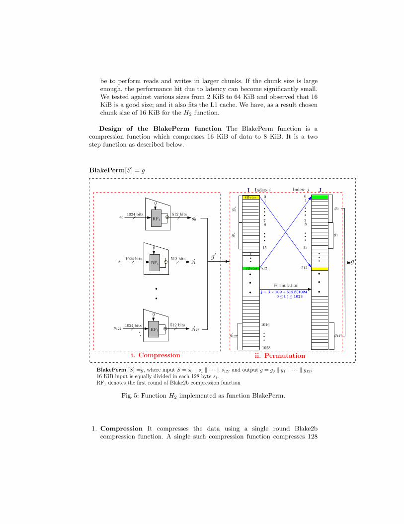
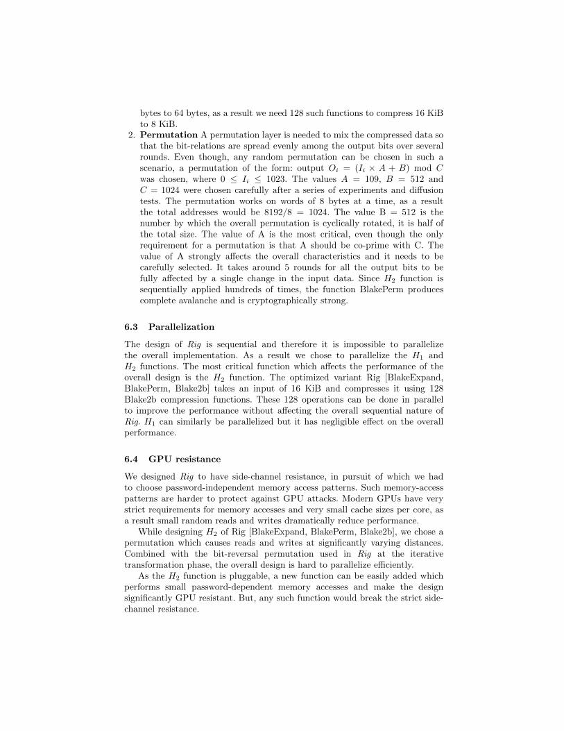
2. Permutation A permutation layer is needed to mix the compressed data sothat the bit-relations are spread evenly among the output bits over severalrounds. Even though, any random permutation can be chosen in such ascenario, a permutation of the form: output Oi = (Ii × A + B) mod Cwas chosen, where 0 ≤ Ii ≤ 1023. The values A = 109, B = 512 andC = 1024 were chosen carefully after a series of experiments and diffusiontests. The permutation works on words of 8 bytes at a time, as a resultthe total addresses would be 8192/8 = 1024. The value B = 512 is thenumber by which the overall permutation is cyclically rotated, it is half ofthe total size. The value of A is the most critical, even though the onlyrequirement for a permutation is that A should be co-prime with C. Thevalue of A strongly affects the overall characteristics and it needs to becarefully selected. It takes around 5 rounds for all the output bits to befully affected by a single change in the input data. Since H2 function issequentially applied hundreds of times, the function BlakePerm producescomplete avalanche and is cryptographically strong.
6.3 Parallelization
The design of Rig is sequential and therefore it is impossible to parallelizethe overall implementation. As a result we chose to parallelize the H1 andH2 functions. The most critical function which affects the performance of theoverall design is the H2 function. The optimized variant Rig [BlakeExpand,BlakePerm, Blake2b] takes an input of 16 KiB and compresses it using 128Blake2b compression functions. These 128 operations can be done in parallelto improve the performance without affecting the overall sequential nature ofRig. H1 can similarly be parallelized but it has negligible effect on the overallperformance.
6.4 GPU resistance
We designed Rig to have side-channel resistance, in pursuit of which we hadto choose password-independent memory access patterns. Such memory-accesspatterns are harder to protect against GPU attacks. Modern GPUs have verystrict requirements for memory accesses and very small cache sizes per core, asa result small random reads and writes dramatically reduce performance.
While designing H2 of Rig [BlakeExpand, BlakePerm, Blake2b], we chose apermutation which causes reads and writes at significantly varying distances.Combined with the bit-reversal permutation used in Rig at the iterativetransformation phase, the overall design is hard to parallelize efficiently.
As the H2 function is pluggable, a new function can be easily added whichperforms small password-dependent memory accesses and make the designsignificantly GPU resistant. But, any such function would break the strict side-channel resistance.

6.5 ASIC/FPGA resistance
The Rig construction is strictly sequential and is therefore non-parallelizable.The compression function H2 (BlakePerm) as explained above, can beparallelized. But, the size of the inputs and outputs (16 KiB to 8 KiB) whichneeds 128 parallel instances of Blake2b compression function is too large forimplementations with a large number of simultaneous Rig instances.
Even though there can be a lot of possibilities of implementations withvarying numbers of compression functions, the overall space requirement stillremains high.
The biggest problem in case of ASIC resistance would however come fromthe memory latency and bandwidth of the DRAM needed for storage of theextremely large state (several hundred megabytes to a few gigabytes). Eventhough the compression functions consume less power because of their simplicity,the latency and very high memory bandwidth requirements would make parallelimplementations on ASIC prohibitively expensive. For example, for a singleinstance of Rig [BlakeExpand, BlakePerm, Blake2b] having n = 4 (5 memorypasses), and 1 GiB of state, the bandwidth on a standard PC exceeds 7.37 GiB/sas shown in Table 2.
7 Performance analysis
The reference implementation of Rig has been done in C language on an IntelCore i7-4770 CPU with 16GB RAM at 2400 MHz. For the implementation of thefirst round of the compression function of Blake2b1 for the function H2, we useAVX2 instructions. Specifically these AVX2 instructions are used to parallelizethe implementation of first round G-function of Blake2b. The following tables(Table 1 and Table 2) show the performance figure in terms of ‘memory hashingspeed’ and ‘DRAM bandwidth’ for different values of parameter n (number ofiterations).The reference implementation is available at: https://github.com/arpanj/Rig.
7.1 Suggested parameters
The performance figures provided in Table 1 and Table 2 show that, as expected,the memory hashing speed for Rig [BlakeExpand, BlakePerm, Blake2b] issignificantly higher than that of the strictly sequential variant.
Due to the wide spectrum of possible uses it is very difficult to suggest optimalvalues for parameters which suits every possible implementation scenario.However, we can suggest values for common applications. For the parameter‘n’ (number of iterations) we suggest values higher than 3. This means thatone should have at least four passes over memory (including setup phase). Forsome scenarios this may be increased to make low memory attacks prohibitivelyexpensive.
1 The idea of using reduced-round Blake2b is inspired from [2,6].

0
2
4
6
8
10
12
0 200 400 600 800 1000 1200
Tim
e in
se
co
nd
s
Memory usage in MB
ScryptRig(n=2)Rig(n=4)Rig(n=6)
Fig. 6: Performance of Rig (at different value of n) and Scrypt.
The memory count value (mc) would depend strongly on the requirement andthe actual use-case. For a server client architecture where the clients are expectedto have enough free RAM, the value can be set to use few tens of megabytes to afew hundred megabytes. In a mobile environment, this can be further reduced toallow for clients with smaller memories. In the case the algorithm is to be usedas a proof-of-work test, large memory requirements of a few gigabytes combinedwith a large ‘n’ value can be set. It is important to keep ‘n’ high (as high as6-10) in case the overall memory cost is very small.The performance of Scrypt (with suggested parameters [13]) and the resultsfrom Table 2 are depicted in Figure 6. The graph shows the memory processingrate when consumable memory to compute the password hash is fixed. Thecomparison shows that the memory consumption of Scrypt is comparativelysmall with time. Scrypt takes approximately 6 seconds for 512 MB memorywhile Rig at n = 2 and n = 4 takes approximately 0.389 seconds and 0.613seconds respectively.
8 Security analysis
Rig satistifies the basic requirement of a non-invertible design for passwordhashing because of the following reasons: (i) the iterative use of underlyingprimitive, the (secure) cryptographic hash function and (ii) the initial hashing ofpassword with random salt and other parameters and the final use of salt withchaining data. This makes recovering password from the hashed output quitechallenging.

Table 1: Performance of RIG [Blake2b, BlakeCompress, Blake2b]
--------------------------------------------------------------------
|1)RIG[Blake2b, BlakeCompress, Blake2b]:Memory Hashing Speed(MiB/s)|
--------------------------------------------------------------------
| M => | 15 M | 30 M | 60 M | 120 M | 240 M | 480 M | 960 M |
--------------------------------------------------------------------
| n = 2 | 681 | 684 | 663 | 675 | 681 | 674 | 659 |
| n = 4 | 383 | 383 | 381 | 388 | 388 | 391 | 392 |
| n = 6 | 268 | 270 | 267 | 275 | 272 | 258 | 270 |
| n = 8 | 211 | 210 | 210 | 212 | 210 | 201 | 209 |
| n = 10 | 174 | 173 | 170 | 173 | 170 | 174 | 170 |
--------------------------------------------------------------------
| Memory Bandwidth (GiB/s) |
--------------------------------------------------------------------
| n = 2 | 3.552 | 3.566 | 3.458 | 3.517 | 3.551 | 3.515 | 3.436 |
| n = 4 | 3.596 | 3.595 | 3.575 | 3.642 | 3.640 | 3.666 | 3.677 |
| n = 6 | 3.638 | 3.665 | 3.624 | 3.737 | 3.693 | 3.500 | 3.666 |
| n = 8 | 3.740 | 3.731 | 3.736 | 3.758 | 3.728 | 3.562 | 3.707 |
| n = 10 | 3.826 | 3.789 | 3.721 | 3.796 | 3.737 | 3.811 | 3.736 |
--------------------------------------------------------------------
Table 2: Performance of RIG [BlakeExpand, BlakePerm, Blake2b]
--------------------------------------------------------------------
|2)RIG[BlakeExpand, BlakePerm, Blake2b]:Memory Hashing Speed(MiB/s)|
--------------------------------------------------------------------
| M => | 64 M | 128 M | 256 M | 512 M | 1 GiB | 2 GiB | 4 GiB |
--------------------------------------------------------------------
| n = 2 | 1377 | 1345 | 1307 | 1326 | 1315 | 1312 | 1318 |
| n = 4 | 858 | 846 | 829 | 845 | 835 | 838 | 833 |
| n = 6 | 621 | 621 | 617 | 618 | 606 | 610 | 619 |
| n = 8 | 500 | 485 | 481 | 490 | 485 | 489 | 489 |
| n = 10 | 403 | 398 | 399 | 402 | 404 | 404 | 402 |
--------------------------------------------------------------------
| DRAM Memory Bandwidth (GiB/s) |
--------------------------------------------------------------------
| n = 2 | 6.728 | 6.575 | 6.389 | 6.478 | 6.429 | 6.412 | 6.439 |
| n = 4 | 7.547 | 7.441 | 7.295 | 7.431 | 7.347 | 7.374 | 7.329 |
| n = 6 | 7.888 | 7.898 | 7.847 | 7.858 | 7.709 | 7.750 | 7.873 |
| n = 8 | 8.309 | 8.070 | 8.003 | 8.152 | 8.072 | 8.123 | 8.126 |
| n = 10 | 8.282 | 8.179 | 8.205 | 8.251 | 8.291 | 8.293 | 8.265 |
--------------------------------------------------------------------
n = no. of iterations, performance figures averaged over 20-iterations.
Another important point is the simple, sequential and symmetric design ofthe scheme. The simplicity makes it easy to understand and sequential design

makes the parallel implementation hard and prevents significant speed up by theuse of multiple processing units.
Flexibility of the design and the independence of the selection of memoryparameter from time parameter makes it unique from existing constructions.
8.1 Resistance against low memory attack
Attacker’s approach An attacker running multiple instances of Rig may tryto do the calculations using smaller part of the memory (low memory) or almostno-memory (memory-free) to reduce the memory cost per password guess. Thisapproach may allow parallel implementations of independent password guesses,utilizing almost all the available processing cores. This may not give advantageover single password hash computation but may increase the overall throughputof password guessing as compared to the legitimate implementation of thealgorithm. Next we explain how feasible the low-memory or memory-free attackapproach is, from the attacker’s point of view.
Attack scenario Varying the required storage values We emphasizethat the goal of analyzing the complexity of low memory attack is to show theapproximate impact on the overall processing cost to implement the algorithmRig. Our construction needs to store two arrays a and k as shown in Figure 1.Therefore we try to compute the time complexity when most of these arrayvalues are not stored. The cost of calculation for the values of array a aredominated by the cost of array k. Therefore, for the simplicity of the evaluationwe consider the calculation cost for array k.
To vary the required storage at each iteration, we assume that we storet consecutive values, 0 ≤ t ≤ m − 1, of both the arrays at iterativetransformation phase. This assumption is without loss of generality as we caneasily calculate the index value of array k from the bit reversal permutationexplained in section 2. We also store the hash chaining values after each iteration.
Effect of bit-reversal permutation on low memory scenario Weuse the bit-reversal permutation to shuffle the access of the array k. The effectof this yields exponential complexity for the low memory scenario. This isbecause at every step we update the values of array k and each updated valuedepends on all previous values. Let at iteration i, 1 ≤ i ≤ n, k[j], 0 ≤ j ≤ m−1,is the required value that is not stored. Then we need to compute the valuek[j] at all previous i − 1 iterations and as the access was not sequential, it isdifficult to calculate the exact complexity. Hence, we compute the expectedtime complexity of a password hashing for memory constrained scenario.
Low memory attack complexity: The algorithm Rig can be computed withtime complexity O((n + 1)mr) and space complexity O(m) where 2m is therequired number of stored values, n is the number of iterations used and r isthe number of rounds. An attacker using reduced memory storage (i.e., 0 tom− 2 stored values) will require a time complexity of O(r ×mn+1) for a single

password computation.
Analysis of low memory attack complexity For the legitimateimplementation of the algorithm, Rig, we need to store m = 2mc values of arraysa and k which are created at the setup phase and repeatedly accessed andupdated at each iteration i of the iterative transformation phase (see Figure 1).Our goal is to analyse the extra cost incurred when we do not store the arrayvalues, and calculate them on the fly at each iteration i where 1 ≤ i ≤ n.Specifically, we analyze the time complexity by varying the possible storage (0to m) of the array values. At each iteration i of the iterative transformationphase, we apply bit reversal permutation (Algorithm 1) on m indices of thearray k which we denote by (1, 2, · · · ,m) → (br[0], br[1], · · · , br[m − 1]) andaccess the output of the permutation sequentially. It is easy to calculate thispermutation for all n-iterations in advance. We calculate the overall costof password hashing depending on whether a value of array k, let, k[br[j]],0 ≤ j ≤ m− 1 is stored or not. As mentioned before, to compute the complexitywe store first t consecutive values of array k (where 0 ≤ t ≤ m − 1) that arerequired for corresponding hash calculations at iterative transformation phase.We also store the hash chaining values after each iteration except the last one,i.e., if the implementation uses n-iterations then we store n − 1 such values.Figure 7 shows the graphical view of the low memory scenario with an examplewhere we store two consecutive values of the arrays required for correspondinghash calculations, shown in red. Other m − 2 values that are calculated on thefly and the corresponding hash calculations are shown in green. The generalapproach is explained below.
We apply the law of total expectation to estimate the expected runningtime for a password hashing, conditioning on the indices of the array k. Thisis because the calculation cost is very high when we do not store the values ofrequired indices of k and is the most influential parameter in the overall attackcomplexity. Therefore, we calculate the probability of a value at a particularindex of array k of being stored when we assume t consecutive values are stored.We also calculate the probability of a value at an index not being stored when(m − t) values are not stored. Further, in case a specific index of array k isnot stored, then we estimate the expected cost to evaluate this element at eachiteration i.
We know that the total required indices are m for the array k. Out of thesem values, we store t values while the remaining m − t values are not stored.Therefore, the probability of a stored and not-stored index is given by
Pr[a value of an index is stored ] =t
m
Pr[ a value of an index is not stored ] =m− tm

For t = 2 we store only 2 values and m−2 values are remained un-stored. Then,the above probabilities are 2
m and m−2m respectively as shown in Figure 7.
H2 H2
H2H2
1 2
(m+ 1) (m+ 2)
α α
k[br[0]]
α
h0
t t t t
k[br[1]] k[br[2]] k[br[m− 1]]
Iteration i = 1
H2H2
(nm+ 1) (nm+ 2)
k[br[0]]
t t
k[br[1]]
t
k[br[2]]
H2
H2
H2 H2
Iteration i = n
E1E1
En
H2
t
(m− 2)×O(m)= O(m2)
Complexity per Phase
k[1]k[0] k[m− 1]k[2]
t t tt
Setup Phase:Generates mvalues ofarray k
(m− 2) ×O(mn)= O(mn+1)
(n+ 1)m
a[0] a[1]
a[0] a[1] k[br[m− 1]]a[m− 1]
a[0] a[1] a[m− 1]
H2
2m
H2O(m)
m
a[m− 1]
Probability= m−2mProbability = 2
m
∗Note: k[br[i]] : is the ith index of array k obtained from bit reversal permutationHere in this example figure we store t = 2 consecutive memory for corresponding hash calculation shown in red
(m− 2) not stored values are shown in green
Fig. 7: Graphical representation of the calculation for the low memory complexityof Rig.
To apply the law of total expectation we apply the following concept.At the setup phase we perform m hash calculations to store m values of array k.Therefore, for these m calculations the complexity of the setup phase is O(m).In our construction, at each iteration i, 1 ≤ i ≤ n, we access the values thatare calculated at the previous iteration i− 1, i.e., every next value is dependenton its previous value. Therefore at the first iteration of iterative transformationphase, if we need to access an element of array k that is not stored, we needto perform maximum m calculations of setup phase for that value. Therefore,at iteration i = 1 the total cost of calculation is (m − t) × O(m) = O(m2) (asmaximum m calculations are required for all m− t not stored values). Similarly,at iteration i = 2, for all m − t not stored values of array k it is required tocalculate maximum m hashes of setup phase to generate the initial values. Thenit is required to check when those values were updated at i = 1. At i = 1, themaximum calculations are: (m − t) × O(m) = O(m2), and similarly at i = 2the total calculations are: (m − t) × O(m2) = O(m3) and so on. This way weestimate the cost of calculation after each iteration of iterative transformation

phase shown in Figure 7 as ‘Complexity per phase’. Now at each iteration weestimate the expected cost of calculation for each value k[br[j]] of array k where0 ≤ j ≤ m − 1. We denote the expected cost at iteration i as Ei. If a valueis already stored then the expected cost of calculation, i.e., E(cost when valueis stored)=1 but if the value is not stored then the expected cost will be thecomplexity till the previous iteration as the required value is dependent on allits previous values. So the expectation at each iteration is as follows:
E1 =
m−1∑j=0
Pr[ value at k[br[j]] is stored ]× [ cost of calculation when k[br[j]] is stored ]
+ Pr[ value at k[br[j]] is not stored ]× E[ cost of calculation k[br[j]] is not stored ]
=m−1∑j=0
( tm
+(m− t
m
)×O(m)
)
E2 =
m−1∑j=0
Pr[ value at k[br[j]] is stored ]× [ cost of calculation when k[br[j]] is stored ]
+ Pr[ value at k[br[j]] is not stored ]× E[ cost of calculation k[br[j]] is not stored ]
=
m−1∑j=0
( tm
+(m− t
m
)×O(m2)
)· · · · · · · · · · · · · · · · · ·
En =
m−1∑j=0
Pr[ value at k[br[j]] is stored ]× [ cost of calculation when k[br[j]] is stored ]
+ Pr[ value at k[br[j]] is not stored ]× E[ cost of calculation k[br[j]] is not stored ]
=
m−1∑j=0
( tm
+(m− t
m
)×O(mn)
)The total cost E after n−iterations:
E = m+ E1 + E2 + · · ·+ En
= m+
m−1∑j=0
( tm
+(m− t
m
)×O(m)
)+
m−1∑j=0
( tm
+(m− t
m
)×O(m2)
)+ · · ·
· · ·+m−1∑j=0
( tm
+(m− t
m
)×O(mk)
)+ · · ·+
m−1∑j=0
( tm
+(m− t
m
)×O(mn)
)
= m+ nt+(m− t
m
)m−1∑t=0
[O(m) +O(m2) + · · ·+O(mn)]
= m+ nt+(m− t
m
)O(mn+1)
Conditioning on the values of t we get the following complexities.

Case (i) : t = 0 implies the case of memory-free attack where the attackerdoes not use any memory.
The expected cost is = m+O(mn+1) ≡ O(mn+1)
Repeating for r-rounds, the complexity of the attack is O(r ×mn+1).Case (ii) : When 1 ≤ t ≤ m− 1, i.e. the case when the attacker stores someof the memories.
The expected cost is =(m− t
m
)O(mn+1) ≡ O(mn+1)
Repeating for r-rounds, the complexity of the attack is O(r ×mn+1)Case (iii) : t = m implies the legitimate implementation of the algorithm.
The complexity is = m+ nm ≡ O(n+ 1)m
Repeating for r-rounds, the complexity is O(n+ 1)mr.
Therefore, the memory-free attack complexity of Rig is O(r×mn+1) where r isthe number of rounds.
8.2 Resistance against collision attack
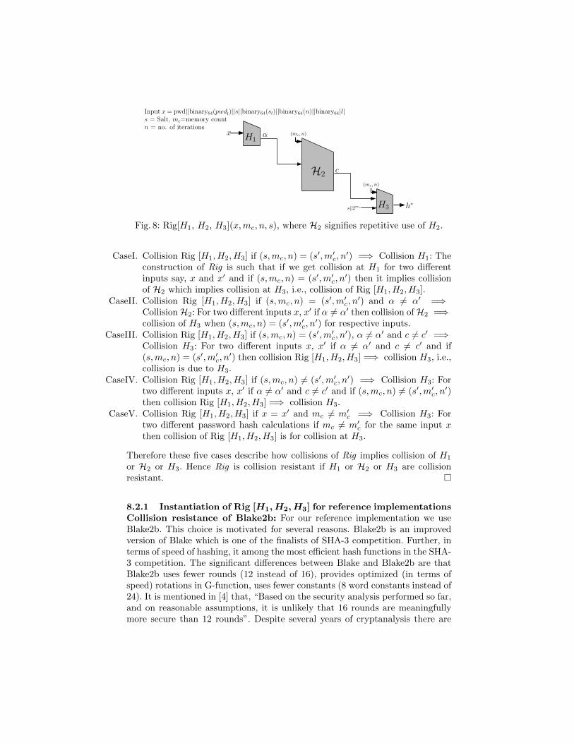
In the design of Rig (see Figure 8) we define three different functions, H1, H2 andH3. The input of H1 is x where x is the concatenation of password, 64-bit valueof password length, salt, 64-bit value of salt length, 64-bit value of n (number ofiterations) and 64-bit value of the output length of password hash. The outputof H1 is α. The function H2 signifies the repetitive computation of function H2
at setup phase and iterative transformation phase (see Figure 1) and generatesthe output c which is the output of iterative transformation phase. Thereforethe inputs of H2 are α, mc and n, where mc is the number of memory count andn, the number of iterations used. Finally H3 takes the concatenation of a 64-bitvalue which is the function of mc and n, output of H2, the value salt and 64-bitvalue of 2mc and produces the output of password hash. Here we are consideringround r = 1 (w.l.o.g). This is because, different values of round, say r and r′
implies collision of H3.
Theorem 1. Collision for Rig means
i. collision for H1, orii. collision for H2 when α 6= α′ and (mc, n) = (m′c, n
′) for two differentpassword hash computations, where mc = m′c = the memory count andn = n′ = number of iterations, or
iii. collision for H3.
Proof. We analyse the collision of Rig with five possible cases as shown inFigure 9. Specifically, we include all possible conditions that results in collisionof H1 or collision of H2 or collision of H3 which implies the overall collision ofRig.
Input x= pwd||binary64(pwdl)||s||binary64(sl)||binary64(n)||binary64|l|s = Salt, mc=memory countn = no. of iterations
H1xH1
α
H1
cH2
(mc, n)
H1H3 h∗
(mc, n)
s||2mc
Fig. 8: Rig[H1, H2, H3](x,mc, n, s), where H2 signifies repetitive use of H2.
CaseI. Collision Rig [H1, H2, H3] if (s,mc, n) = (s′,m′c, n′) =⇒ Collision H1: The
construction of Rig is such that if we get collision at H1 for two differentinputs say, x and x′ and if (s,mc, n) = (s′,m′c, n
′) then it implies collisionof H2 which implies collision at H3, i.e., collision of Rig [H1, H2, H3].
CaseII. Collision Rig [H1, H2, H3] if (s,mc, n) = (s′,m′c, n′) and α 6= α′ =⇒
CollisionH2: For two different inputs x, x′ if α 6= α′ then collision ofH2 =⇒collision of H3 when (s,mc, n) = (s′,m′c, n
′) for respective inputs.CaseIII. Collision Rig [H1, H2, H3] if (s,mc, n) = (s′,m′c, n
′), α 6= α′ and c 6= c′ =⇒Collision H3: For two different inputs x, x′ if α 6= α′ and c 6= c′ and if(s,mc, n) = (s′,m′c, n
′) then collision Rig [H1, H2, H3] =⇒ collision H3, i.e.,collision is due to H3.
CaseIV. Collision Rig [H1, H2, H3] if (s,mc, n) 6= (s′,m′c, n′) =⇒ Collision H3: For
two different inputs x, x′ if α 6= α′ and c 6= c′ and if (s,mc, n) 6= (s′,m′c, n′)
then collision Rig [H1, H2, H3] =⇒ collision H3.CaseV. Collision Rig [H1, H2, H3] if x = x′ and mc 6= m′c =⇒ Collision H3: For
two different password hash calculations if mc 6= m′c for the same input xthen collision of Rig [H1, H2, H3] is for collision at H3.
Therefore these five cases describe how collisions of Rig implies collision of H1
or H2 or H3. Hence Rig is collision resistant if H1 or H2 or H3 are collisionresistant. �
8.2.1 Instantiation of Rig [H1,H2,H3] for reference implementationsCollision resistance of Blake2b: For our reference implementation we useBlake2b. This choice is motivated for several reasons. Blake2b is an improvedversion of Blake which is one of the finalists of SHA-3 competition. Further, interms of speed of hashing, it among the most efficient hash functions in the SHA-3 competition. The significant differences between Blake and Blake2b are thatBlake2b uses fewer rounds (12 instead of 16), provides optimized (in terms ofspeed) rotations in G-function, uses fewer constants (8 word constants instead of24). It is mentioned in [4] that, “Based on the security analysis performed so far,and on reasonable assumptions, it is unlikely that 16 rounds are meaningfullymore secure than 12 rounds”. Despite several years of cryptanalysis there are

no significant attack on Blake. A recent paper cryptanalyzing Blake2b is [7]shows that no collision or preimage attacks exist against Blake2b. In fact, thebest differential against Blake2b covers 3.5 rounds and has a complexity of2480. Therefore Blake2b is quite secure against collision and preimage attacks,properties which we need in our design. For further details on attacks oncompression function and permutation of Blake2b, we refer the reader to [7].Hence, the use of full round Blake2b is enough to claim security of ourconstruction against attacks utilizing collisions or preimages of the underlyinghash function.
H1
H1
H2
H2
c
c′
H3
H3
h∗
h∗′
h∗
h∗′x′
x
h∗
h∗′
CaseIII: Collision Rig[H1, H2, H3] if (s,m, n) = (s′,m′, n′),α 6= α′ and c 6= c′ ⇒ collision of H3
h∗
h∗′
h∗
h∗′
CaseV: Collision Rig[H1, H2, H3] if x = x′
and mc 6= m′c ⇒ collision of H3
(m′c, n)
α′
α H1
H1
H2
H2
c
c′
H3
H3x′
x
(m′c, n)
α′
α
H1
H1
H2
H2
c
c′
H3
H3x′
x
α′
α H1
H1
H2
H2
c
c′
H3
H3x′
x
(m′c, n)
α′
α
H1
H1
H2
H2
c
c′
H3
H3x′
x
(m′c, n)
α
(s,m, n) = (s′,m′, n′)
s||2mc
s||2mc
s||2m′c
CaseIV: Collision Rig[H1, H2, H3] if (s,m, n) 6= (s′,m′, n′),α 6= α′ and c 6= c′ ⇒ collision of H3
(mc, n)
(m′c, n)
(mc, n)
(m′c, n)
(mc, n)
(mc, n)
(mc, n)
α′
s||2m′c
s||2mc
s||2mc
s||2m′c
s||2mc
s||2m′cs||2m′
c
(mc, n)
(mc, n)
(mc, n)
(mc, n)
(mc, n)
(m′c, n)
CaseII: Collision Rig[H1, H2, H3] if (s,mc, n) = (s′,m′c, n
′)and α 6= α′ ⇒ collision of H2
CaseI: Collision Rig[H1, H2, H3] if (s,mc, n) = (s′,m′c, n
′)⇒ collision of H1 ,
(m′c, n)
(m′c, n)
(m′c, n)
Note: Symbol is used to show that values aboveand below the image in each box are different andsymbol to show that the values are same.Symbol denotes the implication relation.
Fig. 9: Five cases showing collisions for Rig [H1, H2, H3].
– Rig [Blake2b, BlakeCompress, Blake2b]Instantiation of H1 and H3 with Blake2b: We use full round Blake2bfor the functions H1 and H3. We need collision resistance of both thefunctions for the security of Rig. Use of Blake2b allows us to claim collisionresistance of H1 and H3 [7].
Instantiation of H2 with BlakeCompress: The function H2 as shown inFigure 8 signifies the repetitive computations of the function H2 and inputsof H2 are α,mc, n. Theorem 1 shows that collision of H2 implies collision ofRig only if H1 gives two distinct outputs say, α, α′ for two different inputsx 6= x′ while corresponding values (mc, n) = (m′c, n
′). We use first round

of Blake2b compression function for the implementation of H2 as shown inFigure 2.
For finalization phase we omit the feed-forward xor’ing as explained inBlake2b (see Figure 3). This choice of implementation is to improve theperformance, but it does not preserve the onewayness as there is no feed-forward xor’ing. In this case it would appear that backward calculation iseasy as H2 computation is then reversible. But due to the design of Rig itis very difficult to perform these backward computations as input values ofH2 are arrays a and k and depends on their values at previous iteration (seeFigure 1). Therefore, we only have the freedom to guess the values of arraya and k to move backward with reverse calculation for the last iteration,say i = n. Last iteration n will fix the values of iteration (n − 1) as valuesare dependent. So we lose the freedom of guessing the values from iteration(n − 1) and onwards and the backward computations become hard. Henceomitting the feed forwardness can compromise the onewayness but the designof the scheme provides no security loss. Now consider two distinct inputs ofH2 as α = H1(x) and α′ = H1(x′) for x 6= x′.
H2 H2
1 2
(m+ 1) (m+ 2)
k[1]k[0] k[m-1]k[2]
α
t t tt
h0a[0] a[1] a[m-1]
H2
m
H2H2
SetupPhase:
α α
Fig. 10: Setup phase uses m inputs generated from α.
Figure 10 shows that m = 2mc number of computations of H2 of the setupphase are generated from these different α or α′ and it will be difficult to findcollision everywhere as values generated from two different inputs are usuallyexpected to be different. The values of array a and k are generated from αor α′ and influence further calculations. Now, consider the last iteration ofiterative transformation phase, i.e., the last layer of 2mc computations of H2
as shown in Figure 11. All these H2 calls use single round Blake2b and aregenerated from the same value α or α′. The input values influenced by α orα′ are shown in red color and most of them will have nonzero difference. Wecan visualize this scenario as similar to the Blake2b construction, instead of12 rounds using 2mc rounds. Use of comparatively large number of roundsprovides enough security. Since we expect the parameter mc ≥ 10, we willhave 1024 rounds of Blake2b compression function. Therefore, we can expectH2 to be collision resistant.
Therefore the choice of reduced round Blake2b does not affect the collisionresistance of the design.

– Rig [BlakeExpand, BlakePerm, Blake2b]
Instantiation of H1 with BlakeExpand and H3 with Blake2b: Asexplained in section 6.2 we are using 128 individual instances of Blake2b(full hash) appended by a counter for the function H1. Therefore a collisionfor H1 means collisions for each of the 128 calls to Blake2b. Therefore,collision resistance of H1 is obtained from the collision resistance of Blake2b.For the function H3 we implement Blake2b (full round), therefore H3 iscollision resistant if Blake2b is so.
Iteration i = n of H2
Input: α (512 bits)
t t t
k[br[2]]
t
round-1 round-2 round-2mc
i= n
(nm+ 2) (n+ 1)m0 0 0
RF1RF1 RF1
(nm+ 1)
H2 implemented with the first round of Blake2b compression function denoted as RF1
and input of RF1=1024 bits
H2 H2 H2
k[br[0]] k[br[1]] k[br[m− 1]]
Fig. 11: H2 implemented with RF1 at iteration i = n.
Instantiation of H2 with BlakePerm: We implement each H2 with twostep functions. The first function, ‘Compression’ executes 128 instances offirst round Blake2b compression function and compresses total 16 KiB inputto 8 KiB. The second function, ‘Permutation’ is a permutation that mixesthe compressed 8 KiB output to spread the bit-relations evenly among theoutput bits (see Figure 5).We can provide similar arguments for the security of H2 as explained for thesequential variant, Rig [Blake2b, BlakeCompress, Blake2b] above.Hence, the above choice of implementation is expected to be secure againstcollision attack.
8.3 Resistance against length extension attack
The length extension attack on hash function works as follows. Hash functionswork on blocks of data iteratively. Let the initial value of a hash be IV =h0. Along message m = m0‖m1‖ . . . ‖ml is processed as follows. First h1 = H(h0,m0)

is computed and then the recursion hi+1 = H(hi,mi) is used for 1 ≤ i ≤ l. Thefinal output is hl+1. An attacker, without knowing the intermediate messageblocks, may simply append a new block m∗ and compute the hash value ofthe message m′ = m0‖m1‖ . . . ‖ml‖m∗, by using one call to the hash functionas H(hl+1,m
∗). In our construction the password is not the only input to thehash function. If an attacker attempts to append the password by any text, thevalue of α will change and it will affect all subsequent blocks. Thus the lengthextension attack is not feasible in our design.
8.4 Resistance against cache-timing attack
As discussed in section 5, our construction accesses array k (see section 4) usinga bit reversal permutation which is password independent. Hence cache timingattack is not possible on our costruction. Further, since the only primitive usedin our scheme is a secure hash function, the security of our scheme can beformulated in terms of the security of the underlying hash function. With thecurrent state-of-the-art we have the possibility of using SHA-3 implementation,or even any of the other finalists of SHA-3 competition, which are resilient toside-channel attacks. Thus our scheme resists cache timing attacks.
8.5 Resistance against denial-of-service attack
In computing, a denial-of-service (DoS) attack is an attempt to make a machineor network resource unavailable to its intended users. This is possible by makingthe server busy injecting lots of request for some resource consuming calculation.It is quite easy if the server uses some slow password hashing technique forauthentication. To handle such situations, the server-relief technique can providesome relief to the server from heavy calculations as the client will do the heavypart of the algorithm. This way we can reduce the chances of DoS attacks withslow password hashing schemes.
9 Conclusions
In this work, we have proposed a secure password hashing scheme Rig based oncryptographic hash functions. Besides supporting necessary and commonly usedfeatures of a password hashing scheme, Rig also supports client-independentupdates and server relief technique. The flexibility in the choice of the twoimportant parameters (memory count and number of iterations) enhances thescope of its implementation. Rig can be implemented in various software andhardware platforms including resource constraint devices.
10 Acknowledgments
We would like to thank the anonymous reviewers of Inscrypt and the contributorsto the PHC mailing list (specially Bill Cox) whose comments helped improve thepaper significantly.

References
1. Password Hashing Competition (PHC), 2014. https://password-hashing.net/
index.html.2. Leonardo C. Almeida, Ewerton R. Andrade, Paulo S. L. M. Barreto, and Marcos
A. Simplıcio Jr. Lyra: Password-Based Key Derivation with Tunable Memory andProcessing Costs. IACR Cryptology ePrint Archive, 2014:30, 2014.
3. Jean-Philippe Aumasson, Samuel Neves, Zooko Wilcox-O’Hearn, and ChristianWinnerlein. BLAKE2: Simpler, Smaller, Fast as MD5. In Michael J. Jacobson Jr.,Michael E. Locasto, Payman Mohassel, and Reihaneh Safavi-Naini, editors, ACNS,volume 7954 of Lecture Notes in Computer Science, pages 119–135. Springer, 2013.
4. Jean-Philippe Aumasson, Samuel Neves, Zooko Wilcox-O’Hearn, and ChristianWinnerlein. BLAKE2: simpler, smaller, fast as MD5. IACR Cryptology ePrintArchive, 2013:322, 2013.
5. Carlos Carvalho. The gap between processor and memory speeds. In Proc. ofIEEE International Conference on Control and Automation, 2002.
6. Joan Daemen and Vincent Rijmen. A new MAC construction ALRED and aspecific instance ALPHA-MAC. In Fast Software Encryption: 12th InternationalWorkshop, FSE 2005, Paris, France, February 21-23, 2005, Revised SelectedPapers, pages 1–17, 2005.
7. Jian Guo, Pierre Karpman, Ivica Nikolic, Lei Wang, and Shuang Wu. Analysis ofBLAKE2. In Josh Benaloh, editor, Topics in Cryptology - CT-RSA 2014 - TheCryptographer’s Track at the RSA Conference 2014, San Francisco, CA, USA,February 25-28, 2014. Proceedings, volume 8366 of Lecture Notes in ComputerScience, pages 402–423. Springer, 2014.
8. Markus Durmuth, Tim Guneysu, Markus Kasper, Christof Paar, Tolga Yalcin, andRalf Zimmermann. Evaluation of Standardized Password-Based Key Derivationagainst Parallel Processing Platforms. In Sara Foresti, Moti Yung, and FabioMartinelli, editors, ESORICS, volume 7459 of Lecture Notes in Computer Science,pages 716–733. Springer, 2012.
9. Christian Forler, Stefan Lucks, and Jakob Wenzel. The Catena PasswordScrambler. Submission to Password Hashing Competition (PHC), 2014.
10. Jim Gray and Prashant Shenoy. Rules of Thumb in Data Engineering. TechnicalReport, MS-TR-99-100, Microsoft Research, Advanced Technology Division.December 1999, Revised March 2000.
11. Thomas Lengauer and Robert Endre Tarjan. Upper and lower bounds on time-space tradeoffs. In Proceedings of the 11h Annual ACM Symposium on Theory ofComputing, April 30 - May 2, 1979, Atlanta, Georgia, USA, pages 262–277, 1979.
12. William Burr Meltem Snmez Turan, Elaine Barker and Lily Chen. NIST:Special Publication 800-132, Recommendation for Password-Based Key Derivation.Computer Security Division Information Technology Laboratory. http://csrc.
nist.gov/publications/nistpubs/800-132/nist-sp800-132.pdf.13. Colin Percival. Stronger key derivation via sequential memory-hard functions.
In BSDCon, 2009. http://www.bsdcan.org/2009/schedule/attachments/87_
scrypt.pdf.14. Niels Provos and David Mazieres. A Future-Adaptable Password Scheme. In
USENIX Annual Technical Conference, FREENIX Track, pages 81–91. USENIX,1999.
15. Robert R. Schaller. Moore’s law: past, present, and future. IEEE Spectrum, June1997.