Embed Size (px)
Citation preview

Article
Ride Comfort Optimization of In-Wheel-Motor Electric Vehicle with In-Wheel Vibration Absorber
Mingchun Liu 1*, Feihong Gu 2, Yuanzhi Zhang 1
1 School of Mechatronics Engineering, Nanchang University, Nanchang 330031, China;
[email protected] 2 School of Automotive Engineering, Jilin University, Jilin 130022, China; [email protected]
* Correspondence: [email protected]; Tel.: +86-18720940773
Abstract: In this paper, an in-wheel vibration absorber for In-wheel-motor electric vehicle (IWM EV) is designed, and a comprehensive control strategy of in-wheel absorber and vehicle suspension is proposed to improve vehicle ride comfort. The proposed in-wheel vibration absorber, designed for suppressing the motor vibration, is composed of a spring and a controllable damper. The values of in-wheel spring stiffness and damper initial coefficient are determined by using the improved particle swarm optimization (IPSO) algorithm, which is carried on the typical driving condition. To deal with the negative interaction effects between vehicle suspension and in-wheel absorber, the linear quadratic regulator (LQR) algorithm is utilized to control suspension damper, and the fuzzy PID method is utilized to control in-wheel damper. Based on the four evaluation indexes including vehicle body vertical acceleration, suspension dynamic deflection, wheel dynamic load and motor wallop, the simulation results show that, the proposed LQR control of suspension effectively improves vehicle ride comfort, and the fuzzy PID control of in-wheel damper exhibits superior performance of motor vibration suppressing in comparison to conventional electric wheel.
Keywords: in-wheel-motor electric vehicle; ride comfort; improved particle swarm optimization; linear quadratic regulator; fuzzy PID control
1. Introduction
In recent years, to tackle the increase of energy crisis and environmental pollution, the electric vehicles (EVs) are widely developed as an essential part of efficient and green transportation of the future. Different with traditional EVs driven by centralized powertrains, in-wheel-motor (IWM) EVs are driven by electric motors mounted in hubs. By replacing the mechanical transmission systems with the independent and direct driving system, the IWMEVs have great potential advantages in dynamics control, space utilization, high driving efficiency, and reliable redundancy driving system, etc. [1-3], which are beneficial to improve vehicle performance. As an ideal carrier to research novel dynamics control system, the IWMEVs are considered as one of the important development direction of the next generation EVs. Nevertheless, there are great challenges in vehicle ride comfort due to the heavy electric wheel. The IWMs greatly increase the unsprung mass, resulting in several harsh vertical negative effects, such as reduction of vehicle ride comfort [4-6], deterioration of road friendliness [7], invalidation of suspension control method [8], reduction of motor reliability under the large wallop [9-11]. These negative effects have greatly restricted the development of IWMEVs.
For vehicle with centralized powertrains, the unsprung mass is relatively small, and vehicle comfort mainly depends on suspension performance. While for IWMEV, the electric wheel is an integration system composed of tire, motor, brake, etc. Road vibration acts on the electric wheel, where the tire and motor are impacted. It is worth to note that, the huge wallop can cause radial relative motion between stator and rotor, which will deteriorate performance and service life of motor [12]. Furthermore, the vibration in the electric wheel is coupled with that of vehicle body, complicating vehicle dynamics characteristics.
Preprints (www.preprints.org) | NOT PEER-REVIEWED | Posted: 21 September 2017 doi:10.20944/preprints201709.0103.v1
© 2017 by the author(s). Distributed under a Creative Commons CC BY license.
Peer-reviewed version available at Energies 2017, 10, 1647; doi:10.3390/en10101647

2 of 16
In order to improve IWMEVs’ ride comfort, the suppression of vertical negative effects has been the hotspot of intensive research. A rich literature mainly focus on three methods, including lightweight design of motor, unsprung mass transfer and optimization of vibration transmission.
Lightweight design of motor is an effective method to reduce electric wheel mass. The axial flux motor, with the advantages of high torque density and power density without cogging effect [13-14], meets all the requirements and limits of EV, and fits the shape and size of the classical-vehicle wheel rim, and is well applied in the electric wheel. Nikam et al. [15] designed a permanent magnet brushless DC motor with segmented rotor type construction for IWMEVs, where, concentrated winding arrangement is used to reduceend-winding volume and copperloss, ensuring lightweight of motor. Takahashi et al. [16] presented a low cost in-wheel axial gap motor using ferrite permanent magnets. Owing to achieve further size and weight reduction, open slot structure was instead of semi-closed slot structure. Experimental results showed that the semi-closed slot structure was effective in realizing size and weight reduction. However, the lightweight of motor has not been widely applied because of material performance and manufacturing cost.
Besides, The IWM can be transferred to the sprung mass as a vibration absorber by utilizing suspended device, which is beneficial to improve vehicle ride comfort in a wide frequency range. Bridgestone Corporation [17] developed an electric wheel with a dynamic vibration absorber, which controls the negative influences on the vertical vibration by utilizing motor mass as the absorber.
Shao et al. [18] designed a dynamic-damping in-wheel-motor driven system, where the suspended motor is operated as a dynamics absorber, and a fault-tolerant fuzzy approach was utilized to control the active suspension of IWMEV. Luo and Tan [19] designed a topological scheme of electric wheel structure with built-in mount system, where, the IWM was separated elastically from unsprung mass by rubber bushing,transferring the mass of motor to be parallel to sprung mass. The rubber bushing absorbed the vibration energy transferred from road to motor, reducing the effects of road excitation on motor air gap and hence improving vertical dynamic characteristics of vehicle. Nevertheless, the suspended devices, such as rubber bushing, are essentially kinds of passive vibration absorb, and the parameters are determined under the typical working conditions, which means that the effectiveness of the method will be reduced at the complicated and varied pavement.
Another method to suppress vertical negative effects of IWM is the optimization of vibration transmission. Oliveira [20] designed an in-wheel semi-active suspension, where the damper could be continuously adjusted to meet the vibration requirements within a certain extent. Ma [21] et al achieved the active control of vertical vibration of the motor by adding a linear motor between the stator and the axle. Jin [22] proposed a MR semi-active suspension system, where, based on the structural designing and parameter matching, the proposed system achieved adjustable damping force to improve vehicle ride comfort. Vibration absorbers under active or semi-active control are considered to be more potential and adaptive methods in improving the ride comfort [23-24]. While, it is difficult to install the absorbers into electric wheel with the space limitation. What’s more, the in-wheel absorbers change the vibration transmission properties. The comprehensive control of in-wheel vibration absorber vehicle suspension has been seldom studied.
To overcome the above mentioned drawbacks, an integrated electric wheel with controllable in-wheel vibration absorber is proposed to improve the vehicle ride comfort of an IWM EV in this study. The proposed in-wheel vibration absorber, composed of a spring and a controllable damper, is to reduce the vertical wallop of the IWM. The improved particle swarm optimization (IPSO) algorithm is utilized to determine the initial parameters of the in-wheel absorber under the typical working condition. In order to coordinate the vehicle suspension with in-wheel absorber, the linear quadratic regulator algorithm (LQR) is utilized to semi-actively control the suspension to improve vehicle ride comfort, and a fuzzy PID controller is utilized to control the in-wheel damper to reduce the vertical wallop of the IWM adaptively. The effectiveness of the proposed method is validated through simulation based on the software of MATLAB/Simulink under the various typical condition.
The remainder of this paper is organized as follows: The structure of electric wheel with in-wheel vibration absorber and a 1/4 vehicle dynamics model are introduced in Section 2. The comprehensive control strategy of suspension and in-wheel absorber is elaborated in Section 3.
Preprints (www.preprints.org) | NOT PEER-REVIEWED | Posted: 21 September 2017 doi:10.20944/preprints201709.0103.v1
Peer-reviewed version available at Energies 2017, 10, 1647; doi:10.3390/en10101647

3 of 16
Section 4 provides the details about simulations for the proposed control strategy, followed by the key conclusions summarized in Section 5.
2. Structure Design and Dynamics Modeling of Electric Wheel
2.1 Structure Design of Electric Wheel with In-Wheel Vibration Absorber
In conventional electric wheel, the motor rotor is rigidly connected with tire, and the stator is also rigidly connected with wheel axle, which means that the IWMs take a large proportion of unsprung mass. In this situation the pavement load acts directly to the tire and motor, reducing the motor service life and working stability, meanwhile reducing the ride comfort of the vehicle. In this study, the rigid connection between the stator and axle is changed to the flexible connection.
1-Tire; 2-Motor rotor; 3-Motor stator; 4-Stator extension; 5-In-wheel controllable damper;
6-In-wheel spring; 7-Vehicle suspension; 8-Steering kunckle; 9- Vehicle body Figure 1 Structure of electric wheel with in-wheel vibration absorber
As shown in Figure 1, the proposed electric wheel consists of following parts: (1) In-wheel motor (IWM). The IWM is a permanent magnet synchronous motor with outer
rotor. Two sides of the rotor are connected to wheel hub and brake disc through bolts, respectively, to drive and brake wheel. One outer port of hollow motor stator is extended to be a square structure with inner circle to install the in-wheel spring and damper.
(2) In-wheel vibration absorber. The proposed In-wheel vibration absorber is composed of a spring and a controllable damper. The spring is mounted on outer edge of the motor extension, and connected with vehicle body. The spring can passively absorb the vibration of motor and body. Besides, the controllable damper, such as magnetic rheological damper, is installed into an annular sleeve to sheathe outside of wheel axle. The damper force can be controlled according to the driving condition to suppress the vertical vibration of the motor.
It is worth to note that this study focuses on damper force control for vibration absorbing, rather than the type of controllable damper. So we assume that the damper can precisely output controlled force to meet the requirement of vehicle performance.
2.2 Dynamics Modeling of 1/4 Vehicle
The simplified model of 1/4 vehicle with the proposed electric wheel is shown in figure 2. There are two vibration system in the 1/4 vehicle, including the in-wheel vibration absorber and vehicle suspension. Considering the stator and motor as an integrated part, and ignoring their relative vertical motion inside the motor, the dynamics model of 1/4 vehicle is shown in figure 3. Where, ms, mt, me1, me2 are 1/4 body mass, wheel assembly mass (including tire, rim, axle, etc.), motor stator mass, motor rotor mass (including rotor and brake disc), respectively. Ks, Kt, Ke, Kr are suspension stiffness, tire vertical stiffness, in-wheel spring stiffness, bolt stiffness, respectively. Cs
and Ce are the controllable damping coefficients of vehicle suspension and in-wheel damper, respectively. x1, x2, x3 are vertical displacement of wheel assembly, in-wheel motor and vehicle body, respectively. q(t) is pavement input.
Preprints (www.preprints.org) | NOT PEER-REVIEWED | Posted: 21 September 2017 doi:10.20944/preprints201709.0103.v1
Peer-reviewed version available at Energies 2017, 10, 1647; doi:10.3390/en10101647
4 of 16
ms
mt
me1
Ks Cs
Kr
Ke
Ce
x3
x2
x1
q(t)
me2
Kt
Figure 2 Simplified structure of 1/4 vehicle Figure 3 Dynamics model of 1/4 vehicle
According the dynamic model, the differential equations of 1/4 vehicle can be expressed as:
1 1 3 1 3 1 2 1 2 1( ) ( ) ( ) ( ) ( ) 0t s s r e tm x K x x c x x K x x c x x K x q+ − + − + − + − + − = (1)
1 2 2 2 1 2 1 2 3( + ) ( ) ( ) ( ) 0e e r e em m x K x x c x x K x x+ − + − + − = (2)
3 3 1 3 1 3 2( ) ( ) ( ) 0s s s em x K x x c x x K x x+ − + − + − = (3)
There are 3 degrees of freedom in the 1/4 vehicle model, including the vertical motions of vehicle body, in-wheel motor and tire. Considering one-mass under the condition of undamped vibration, the equations (1)-(3) are simplified as:
1 1( ) 0t s r tm x K K K x+ + + = (4)
1 2 2 2( + ) ( ) 0e e r em m x K K x+ + = (5)
3 3( ) 0s s em x K K x+ + = (6)
Based on equations (4)-(6), the undamped natural frequencies of tire, in-wheel motor and body can be calculated as:
1 2
1( ) /
21
( ) / ( )21
( ) /2
t s r t t
e r e e e
s s e s
K K K m
K K m m
K K m
ωπ
ωπ
ωπ
= + + = + + = +
(7)
Where tω , eω and sω are undamped natural frequency of tire, motor and body, respectively.
The bolt stiffness Kr is far greater than Ks, Kt and Ke, so tω , eω are approximately equal and much
larger than sω , and exceed range of normal road excitation frequency, which means that the tire
and motor will vibrate together, rather than vibrate free as a single-mass. Therefore, taking the tire
and motor as electric wheel mass, the undamped natural frequencies of electric wheel and body are:
1 2
1( ) / ( )
21
( ) /2
w s e t t e e
s s e s
K K K m m m
K K m
ωπ
ωπ
= + + + + = +
(8)
Preprints (www.preprints.org) | NOT PEER-REVIEWED | Posted: 21 September 2017 doi:10.20944/preprints201709.0103.v1
Peer-reviewed version available at Energies 2017, 10, 1647; doi:10.3390/en10101647

5 of 16
3 Optimization Control of In-Wheel Vibration Absorber and Vehicle Suspension
As mentioned above, the proposed in-wheel vibration absorber and vehicle suspension are controllable to reduce motor wallop and improve vehicle ride comfort. Four factors are taken as evaluation indexes to evaluate the control effectiveness, including vehicle body vertical acceleration as, suspension dynamic deflection fd, wheel dynamic load Fd and motor wallop Fe.
Ke Ce0
Dynamic Model
speed
Road Roughness
BodyVertical
Acceleration
Suspension Dynamic
Deflection
Wheel Dynamic
Load
MotorVertical Wallop
LQR control of vehicle suspension damper
Fuzzy PID control of in-wheel damper
Cs Ce
Road vertical excitation
Parameters matching of in-wheel vibration absorber
(IPSO algorithm)
Figure 4 Comprehensive control strategy
As shown in figure 4, the comprehensive control strategy of the in-wheel absorber and vehicle suspension mainly includes the following two aspects:
(1) Initial parameters matching of the in-wheel vibration absorber. The IWM vibration performance is mostly influenced by the in-wheel absorber. Under the typical condition, the improved particle swarm optimization (IPSO) algorithm is utilized to determine the in-wheel spring stiffness Ke and damper initial value Ce0.
(2) Comprehensive control of the vehicle suspension damper and the in-wheel damper. In order to restrain the vertical vibration of vehicle body and the IWM, the body acceleration as and the motor wallop Fe are selected as the primary optimization variables, and the suspension dynamic deflection fd and the wheel dynamic load Fd as the auxiliary optimization variables. The linear quadratic regulator algorithm (LQR) algorithm is utilized to control vehicle suspension damper to suppress vehicle body vibration, and the fuzzy PID controller is to adjust the in-wheel damper to reduce motor wallop.
3.1. Initial parameters matching of the in-wheel damping system
Based on transfer function, the Fourier transform method is always employed to achieve parameters matching [25]. While, it is difficult to calculate the transfer function of a system with multi-degree-of-freedom. And some scholars utilizes the genetic algorithm to match the parameters of vehicle suspension [22]. It is complicated to programme the genetic algorithm with memory function characteristic, which limits the effectiveness.
As shown in figure 5, the Improved Particle Swarm Optimization (IPSO) algorithm, based on the social behavior of individuals and groups with the advantages of simple programming and easy implementation [26], is utilized to determine the in-wheel absorber’s parameters. When parameters are matched by IPSO, each particle represents a set of two-dimensional constants containing in-wheel spring stiffness and damper coefficient. The particles can dynamically update optimization speed to achieve the optimal trajectory.
Preprints (www.preprints.org) | NOT PEER-REVIEWED | Posted: 21 September 2017 doi:10.20944/preprints201709.0103.v1
Peer-reviewed version available at Energies 2017, 10, 1647; doi:10.3390/en10101647

6 of 16
Initial population of K e0 and Ce0
Assigning the group to Ke and Ce
Solving the objective function
Reaching the maximum iteration
Algorithm ends with matched Ke and Ce0
Updatding particles’ location and speed. Generating a new population
Y
N
Figure 5 Initial parameters matching of the in-wheel absorber based on IPSO Algorithm
3.1.1. Updating Particles’ Lacation and Speed
Considering the parameters matching of in-wheel spring and damper as a two-dimensional optimization problem, the updating functions of particles’ optimization speed and positions can be expressed as:
1 1 2 2( 1) ( ) ( ( ) ( )) ( ( ) ( ))ij ij ij ij ij ijv t W v t r c pbest t x t r c gbest t x t+ = ⋅ + ⋅ ⋅ − + ⋅ ⋅ − (9)
( 1) ( ) ( 1)ij ij ijx t x t v t+ = + + (10)
Where i is particle number. j is optimal dimension number, and t is iterations number. vij(t) and xij(t) respectively represent the optimization speed and position at the tth iteration. pbestij (t) is the partial optimal position, while gbestij (t) the global optimal position. W is the inertia weight factor. c1 and c2 are the cognitive learning factor and the social learning factor, respectively. r1 and r2 are the random numbers in [0,1].
The inertia weight factor is an important index which strongly affects optimization effect. When the inertia weight factor is large, the global optimization ability of IPSO is strong, but the convergence ability is worse. When the inertia weight factor is small, the global search ability is weak, but the local search ability is strong and the search results are easy to converge. Therefore, it is necessary to dynamically adjust the inertia weight factor to improve flexibility of IPSO. In early stage of the algorithm, a large inertial weight factor is set to increase global search ability. While in later period, a relatively small value is to increase the local search ability of the particle near the optimal solution, meanwhile, the convergence speed is accelerated.
At present, adjusting the inertia weight factor is mainly based on linear or nonlinear decreasing method. The linear method has the advantages of easy to control, intuitive effectiveness, but the accuracy of parameter matching is often not optimistic. In this study, nonlinear decreasing method is employed to adjust the inertia weight factor. The adjustment scheme for the inertia weight is a decreasing function based on the tangent function, and the expression is as follow:
2 1 2 max( ) ( ) tan(0.875 (1 / ))W t W W W t t= + − ⋅ ⋅ − (11)
Where t is the current iteration number, and tmax is the maximum number of iterations. W1 is the inertia weight factor in early stage, while W2 in later period. W1 and W2 are set to 0.9 and 0.4, respectively. Thus, W (1) is 0.9, and W(tmax) = 0.4. The constant of 0.875 ensures that the variation range of W is [0.4, 0.9].
3.1.2. Solving Objective Funtion
As evaluation indexes, the four factors, including vehicle body vertical acceleration as, suspension dynamic deflection fd, wheel dynamic load Fd and motor wallop Fe, can be expressed as:
Preprints (www.preprints.org) | NOT PEER-REVIEWED | Posted: 21 September 2017 doi:10.20944/preprints201709.0103.v1
Peer-reviewed version available at Energies 2017, 10, 1647; doi:10.3390/en10101647
7 of 16
3
3 1
1
1 2 2
( )
( )
s
d
d t
e e e
a x
f x x
F K q x
F m m x
= = − = − = +
(12)
In order to compare performance of the proposed electric wheel with that of the conventional electric wheel, taking the in-wheel stiffness Ke and damping coefficient Ce0 as optimization variable, the objective function is established as:
0
( ) ( ) ( ) ( )( , )
( ) ( ) ( ) ( )s d d e
e es d d e
a f F FJ K C
a f F F
σ σ σ σα β λ ηω ω ω ω
= ⋅ + ⋅ + ⋅ + ⋅ (13)
Where as(σ), fd(σ), Fd(σ) and Fe(σ) respectively represent the RMS values of as, fd, Fd and Fe of IWMs EV with the proposed electric wheel. as(ω), fd (ω), Fd (ω) and Fe (ω) are the RMS values of the four indexes of the IWMs EV with conventional electric wheel, respectively. α, β, λ and η are the weight coefficient of the four indexes, respectively.
According to the requirements of "primarily optimizing the body vertical acceleration and the motor wallop, and secondarily optimizing the suspension dynamic deflection and the wheel dynamic load", α and η are both set to 2, and β and λ are both set to 1.
In order to guarantee the wheel-ground adhesion and vehicle driving stability, the probability of the wheel moving off the road should be less 0.15%, and the probability of the suspension impacting the limit block should be less than 0.3%, and the constraint condition is as follows [29, 30]:
1
3dF Gσ ≤ ⋅ , 1[ ]
3df dfσ ≤ ⋅ (14)
Where G is the static load on the wheel as G= (ms+mt+me1+me2)g. [fd] is the allowable value of the suspension dynamic deflection, it is set to 80mm.
In this study, the motor rotor and the rim are connected by bolts. To ensure the performance of motor, the vertical displacement between the hub and motor is limited to less than 6mm, and the RMS value is less than 2.5mm. That is:
2 1( ) 6 mmx xMax − ≤ ,
2 1( ) 2.5 mmx xσ − ≤ (15)
The basic parameters of the IPSO algorithm are as follows: The population size is set to 30. The inertia weight factor is based on the nonlinear decreasing adjustment method, where the initial value is 0.9, and the final value is 0.4. The maximum number of iterations is 200. The acceleration factor c1 and c2 are 2.The reference range of parameter Ke is [0, 30000] N/m, and the reference range of Ce0 is [0, 8000] N·s/m).
Under the typical condition of the C-class pavement at speed of 70 km/h, the optimized parameters of in-wheel spring Ke and damper Ce0 are:
Ke=2615 N/m , Ce0=3226 N·s/m (16)
3.2. LQR control of the vehicle suspension damper
The proposed in-wheel vibration absorber is to reduce motor wallop, meanwhile, it changes the dynamics characteristics of vehicle, which leads to ineffectiveness of the original suspension. Therefore, it is necessary to control vehicle suspension according vehicle states. In this study, the vehicle suspension damper is controlled to improve vehicle ride comfort by utilizing the linear quadratic regulator (LQR) algorithm.
According equations (1)-(3), 1/4 vehicle model can be expressed as linear state equation as:
x Ax Bu Gw
y Cx Du
= + + = +
(17)
Where x is variable states matrix. y is outputs matrix. u is the controlled force of suspension damper. A, B, C, D and G are coefficient matrixes. w is road excitation (t)q . They are expressed as:
Preprints (www.preprints.org) | NOT PEER-REVIEWED | Posted: 21 September 2017 doi:10.20944/preprints201709.0103.v1
Peer-reviewed version available at Energies 2017, 10, 1647; doi:10.3390/en10101647

8 of 16
T3 1[ ( ) ]3 1 t 2y x x - x K q x x= −
[ ( )]u u t=
1 2 1 2 1 2 1 2
( ) 0
( ) ( ) 0 ( ) 0 ( ) 0
0 0 0
1 1 0 0 0 0 0
1 0 1 0 0 0 0
0 1 1 0 0 0 0
1 0 0 0 0 0 0
s e t e t s t r t s t t t
e e e e e e r e e e e e
s s s s s s e s
C C m C m C m K m K m K m
C m m C m m K m m K m m
C m C m K m K m
A
− + + − + − + + − − − = − −
− −
[ ]T1 0 1 0 0 0 0t sB m m= −
1 2 1 2 1 2 1 2
0 0 0
0 0 0 0 1 0 0
0 0 0 0 0 0
( ) ( ) 0 ( ) 0 ( ) 0
s s s s s s e s
t
e e e e e e r e e e e e
C m C m K m K m
CK
C m m C m m K m m K m m
− − − = + − + − + +
[ ]T
s1/m 0 0 0D =
[ ]T0 0 0 0 0 0 1G =
The objective function is established based on the four evaluation indexes, including vehicle body vertical acceleration, suspension dynamic deflection, wheel dynamic load and motor vertical acceleration, as shown follow
[ ]{ }22 2 21 3 2 3 1 3 1 4 20
1( ) ( ) dt
2 tJ q x q x x q K q x q x∞
= + − + − + (18)
Where q1, q2, q3, q4 are the weighed coefficients of vehicle body vertical acceleration, suspension dynamic deflection, wheel dynamic load and motor vertical acceleration.
Based on the equation (17), the objective function in equation (18) can be deuced as:
0
1( 2 )
2T T TJ x Qx u Ru x Nu dt
∞= + + (19)
Where Q is the weighted coefficient matrix of state variables, and R is the weighted coefficient matrix of input variables. Q and R are both positive definite matrices. N is the associated matrix of Q and R. They can be deduced as:
( )1 2 3 4, , , , , ,p p p pT T TQ C Q C R D Q D N C Q D Q diag q q q q= = = = (20)
Based on the optimal control theory, the optimal solution of objective function (19) is:
( )u t K x= − (21)
Where K is feedback gain matrix, which can be solved by the Riccati equation as follows:
1 0T T TAK KA Q KBR B K GwG−+ + − + = (22)
In MATLAB software, the feedback gain matrix K can be solved by using the LQR function: [K, S, E] = LQR (A, B, Q, R, N)
Preprints (www.preprints.org) | NOT PEER-REVIEWED | Posted: 21 September 2017 doi:10.20944/preprints201709.0103.v1
Peer-reviewed version available at Energies 2017, 10, 1647; doi:10.3390/en10101647

9 of 16
As shown in the objective function equation (18), the weighed coefficients q1, q2, q3, q4 enormously influence the optimization effectiveness. In this study, q1, q2, q3, q4 are obtained by using the IPSO introduce above, and they are:
q=[q1 q2 q3 q4]= [6.17 8025.6 0.000015 0.106] (23)
3.3. Fuzzy PID control of in-wheel damper
The in-wheel vibration absorber with the matched parameters above can reduce motor wallop effectively in most instance. However, the road excitation is complex and varied, which makes the in-wheel absorber with fixed parameters can not exploit the optimum performance. Besides, the in-wheel absorber intercouples with vehicle suspension. It is essential to control the in-wheel absorber to further improve vehicle ride comfort.
In this section, a fuzzy PID controller is designed to adjust the in-wheel damper force. A two-dimension fuzzy controller is employed to determine values of Kp, Ki and Kd of PID controller. The motor vertical acceleration Eae and its gradient ECae are taken as inputs of the fuzzy controller. The main parameters of fuzzy controller are as follows:
(1) The basic domains of Eae and ECae are set to [-6, 6] and [-60, 60], respectively, and the relevant fuzzy domains are both set to [-6, 6]. The quantization factors are set to ke = 1, kec = 0.1.
(2) The basic domains of output Kp, Ki and Kd are set to [-60, 60], [-0.6, 0.6], [- 0.00006, 0.00006], respectively, and the relevant fuzzy domains are all set to [-6, 6]. The scale factors are set to kp = 10, ki = 0.1, kd = 0.00001. The initial values of Kp, Ki and Kd are set to as:
Kp0=30, Ki0=0.27, Kd0=0.00001 (24) (3) Seven fuzzy languages are selected to describe the values of inputs and outputs. They are
Positive-Big (PB), Positive-Medium (PM), Positive-Small (PS), Zero (Z), Negative-Small (NS), Negative-Medium (NM), Negative-Big (NB).
(4) All fuzzy subsets’ membership functions are selected as triangular functions.
Table 1 Fuzzy rules for Kp
ECae Eae
NB NM NS Z PS PM PB
NB PB PB PM PM PS PS Z NM PB PB PM PM PS Z Z NS PM PM PS PS Z NS NM Z PM PS PS Z NS NM NM
PS PS PS Z NS NS NM NM PM Z Z NS NM NM NM NB PB Z NS NS NM NM NB NB
Table 2 Fuzzy rules for Ki
ECae Eae
NB NM NS Z PS PM PB
NB NB NB NB NM NM Z Z NM NB NB NM NM NS Z Z NS NM NM NS NS Z PS PS Z NM NS NS Z PS PS PM
PS NS NS Z PS PS PM PM PM Z Z PS PM PM PB PB PB Z Z PS PM PB PB PB
Preprints (www.preprints.org) | NOT PEER-REVIEWED | Posted: 21 September 2017 doi:10.20944/preprints201709.0103.v1
Peer-reviewed version available at Energies 2017, 10, 1647; doi:10.3390/en10101647

10 of 16
Table 3 Fuzzy rules for Kd
ECae Eae
NB NM NS Z PS PM PB
NB NB NB NB NM NM Z Z NM NB NB NM NM MS Z Z NS NM NM NS NS Z PS PS Z NM NS NS Z PS PS PM
PS NS NS Z PS PS PM PM PM Z Z PS PM PM PB PB PB Z Z PS PM PB PB PB
Based on a large number of simulations, fuzzy rules for Kp, Ki and Kd are established, as shown in table 1, table 2 and table 3, respectively. The relevant fuzzy surface of Kp, Ki and Kd are shown in figure 6(a)-(c).
-6 -4 -2 0 2 4 6
-6-4-20246
-4-2024
Eae
ECae
Kp
-6 -4 -2 0 2 4 6
-6-4-20246
-4-2024
Eae
ECae
Ki
-6 -4 -2 0 2 4 6
-6-4-20246
-4-2024
Eae
ECae
Kd
(a) Fuzzy surface for Kp (b) Fuzzy surface for Ki (c) Fuzzy surface for Kd
Figure 6 Fuzzy surfaces for Kp, Ki and Kd
In order to suppress the motor vibration, motor vertical acceleration ae is taken as the input of PID controller. The controlled damper coefficient ceCΔ and force ceFΔ are expressed as:
3 1
d ( )1( ) ( )d
d
( )
ece p e e d
i
ce ce
a tC K a t a t t K
K t
F C x x
Δ = + +Δ = Δ −
(25)
4. Simulations and Discussions
In order to verify the performance of the proposed in-wheel vibration absorber and control algorithms, the simulations under the typical conditions, including the random pavement and pulse pavement, were carried out based on Matlab/Simulink software.
ms
mt me
Ks Cs
x2
x1
q(t)Kt
ms
mt
me1
Ks Cs
Kr
Ke
Ce
x3
x2
x1
me2
Kt
q(t)
ms
mt
me1
Ks Cs
Kr
Ke
Ce
x3
x2
x1
q(t)
me2
Kt
Figure 7 NWR-PS scheme Figure 8 WPR-PS scheme Figure 9 WPR-SS scheme
Preprints (www.preprints.org) | NOT PEER-REVIEWED | Posted: 21 September 2017 doi:10.20944/preprints201709.0103.v1
Peer-reviewed version available at Energies 2017, 10, 1647; doi:10.3390/en10101647

11 of 16
The following IWM EVs with different electric wheel schemes are applied in the simulations: (1) The conventional electric wheel scheme without in-wheel absorber, used in the passive
suspension of vehicle (marked as NWR-PS), as shown in Figure 7. (2) The electric wheel scheme with in-wheel passive absorber, used in the passive suspension of
vehicle (marked as WPR-PS), as shown in Figure 8. (3) The electric wheel scheme with in-wheel passive absorber, used in the semi-control
suspension of vehicle (marked as WPR-SS), as shown in Figure 9. (4) The electric wheel scheme with in-wheel semi-control absorber proposed in this paper, used
in the semi-active suspension of vehicle (marked as WSR-SS), as shown in Figure 3. The basic parameters of the above IWM EVs are as shown in Table 4:
Table 4 Basic parameters of the vehicle models Parameters Notation units value
1/4 Body mass ms Kg 292
Suspension stiffness Ks N/m 17000
Suspension damping Cs0 N·S/m 1317
Vertical stiffness of tire Kt N/m 241600
In-wheel spring stiffness Ke N/m 2615
In-wheel damper coefficient Ce0 N·S/m 3226
Mass of tire mt Kg 40
Mass of motor stator me1 Kg 15
Mass of motor rotor me2 Kg 30
Bolts stiffness Kr N/m 5000000
4.1 Simulation under pavement random excitation
The simulation was carried out at the C-class pavement with speed of 70km/h. The power spectral density (PSD) curves of vehicle body vertical acceleration, motor vertical wallop, wheel dynamic load, and suspension dynamic deflection are shown in Figure 10-13.
It is worth to note that, as expressed above, the tire and IWM are considered as an integration mass of electric wheel in spectral analysis. Based on equation (8) and vehicle parameters in table4, in the IWM EVs with in-wheel absorbers, including WPR-PS, WPR-SS and WSR-SS, the numerical calculations of natural frequencies of electric wheel w1w and vehicle body w1s are:
1 18.83Hz, 1.31Hzw sω ω= = (26)
In the IWM EVs without in-wheel absorbers, including NWR-PS, the numerical calculations of natural frequencies of electric wheel w2w and vehicle body w2s are:
2 28.78Hz , 1.21Hzw sω ω= = (27)
It indicates that, because of the relatively small value of in-wheel spring stiffness Ke, the natural frequencies of wheel and body in IWM EV with in-wheel absorber are slightly larger than them in IWM EV without in-wheel absorber. The following frequency characteristics would illustrate it, too.
Preprints (www.preprints.org) | NOT PEER-REVIEWED | Posted: 21 September 2017 doi:10.20944/preprints201709.0103.v1
Peer-reviewed version available at Energies 2017, 10, 1647; doi:10.3390/en10101647

12 of 16
0 2 4 6 8 10 12 14 16 18 20
0.02
0.04
0.06
0.08
0.1
Frequency (Hz)
PS
D o
f B
ody
Ver
tical
Acc
eler
atio
n (m
2 /s3 )
NWR-PS
WPR-PSWPR-SS
WSR-SS
Figure 10 The PSD curve of vehicle body vertical acceleration
Figure 10 shows the PSD curves of vehicle body vertical acceleration. It can be seen that, at the natural frequency of electric wheel (about 8.8Hz), compared with NWR-PS, the other three electric wheels make vehicle body vertical acceleration much small, which indicates that the in-wheel absorb is beneficial to suppress body vibration at the natural frequency of wheel. Besides, at the natural frequency of vehicle body (about 1.3Hz), body vertical acceleration of WPR-PS is larger than that of NWR-PS, which indicates that the in-wheel absorber deteriorates suspension performance in some sense. It is worth to note that, body vertical accelerations of WPR-SS and WSR-SS are much smaller than that of the others, which means the control of suspension overcomes the negative effect of in-wheel absorber and improve vehicle ride comfort.
0 5 10 15 200
2
4
6
8
10
Frequency (Hz)
PS
D o
f M
otor
Ver
tical
Wal
lop
(N2 ·s
)
NWR-PS
WPR-PS
WPR-SS
WSR-SS
Figure 11 The PSD curve of motor vertical wallop
Figure 11 shows the PSD curves of motor vertical wallop. It can be seen that, at the natural frequency of electric wheel (about 8.8Hz), motor vertical wallop of NWR-PS is distinctly larger than that of the other three schemes, which indicates that the in-wheel absorber effectively reduces motor vertical wallop. Especially, motor vertical wallop of WSR-SS is smallest, which means the control of in-wheel damper further restrain vibration in the wheel.
Preprints (www.preprints.org) | NOT PEER-REVIEWED | Posted: 21 September 2017 doi:10.20944/preprints201709.0103.v1
Peer-reviewed version available at Energies 2017, 10, 1647; doi:10.3390/en10101647
13 of 16
0 2 4 6 8 10 12 14 16 18 200
2
4
6
8x 10
4
Frequency (Hz)
PS
D o
f W
heel
Dyn
amic
Loa
d (N
2 ·s)
NWR-PS
WPR-PS
WPR-SS
WSR-SS
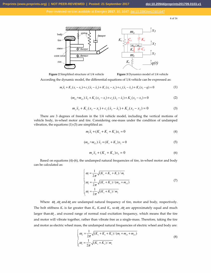
Figure 12 The PSD curve of wheel dynamic load
Figure 12 shows the PSD curves of the wheel dynamic load. It can be seen that the wheel dynamic load follows similar tendency with the motor wallop, where the WSR-SS has the best performance. This is due to the mechanical restrains between wheel and motor, which makes motor vibrate in sync with the wheel.
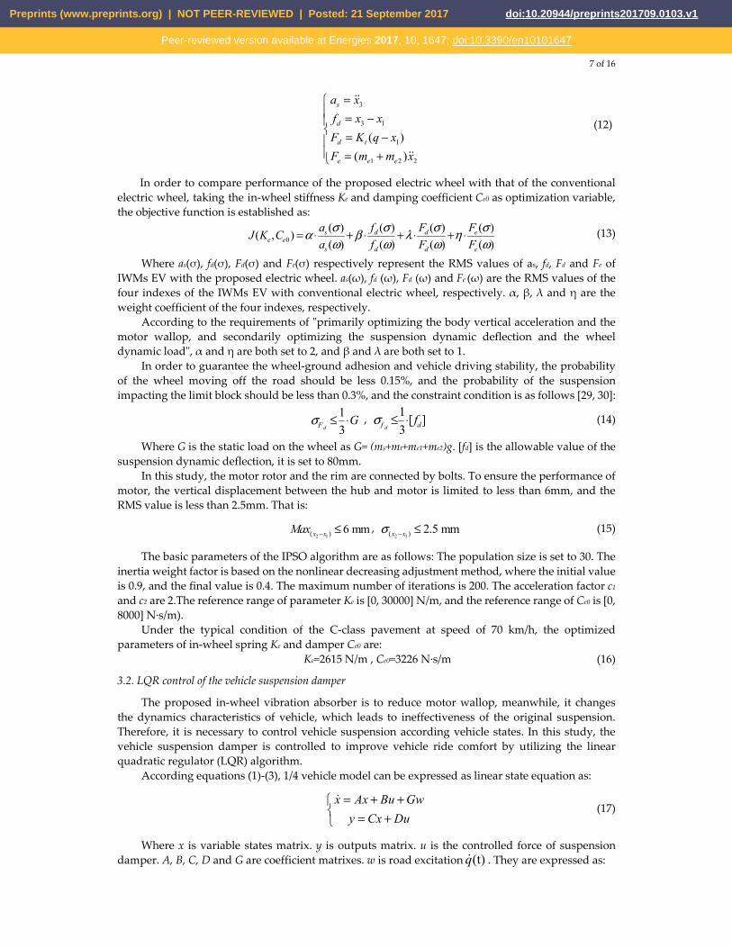
Figure 13 shows the PSD curves of suspension dynamic deflection. It can be seen that, at the natural frequency of vehicle body (about 1.3Hz), suspension dynamic deflections of WPR-SS and WSR-SS are much smaller than that of NWR-PS and WPR-PS, which indicates that the control of suspension damper improves vehicle ride comfort.
0 2 4 6 8 10 12 14 16 18 200
0.5
1
1.5x 10
-5
( )Frequency HZ
PS
D o
f S
uspe
nsio
n D
ynam
ic
Def
lect
ion
(m 2
·s)
NWR-PS
WPR-PS
WPR-SS
WSR-SS
Figure 13 The PSD curve of suspension dynamic deflection
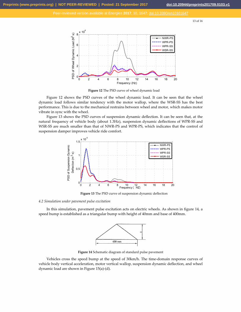
4.2 Simulation under pavement pulse excitation
In this simulation, pavement pulse excitation acts on electric wheels. As shown in figure 14, a speed bump is established as a triangular bump with height of 40mm and base of 400mm.
Figure 14 Schematic diagram of standard pulse pavement
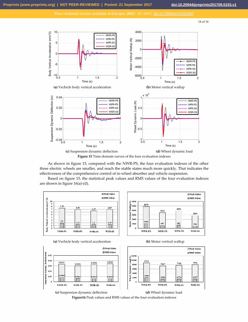
Vehicles cross the speed bump at the speed of 30km/h. The time-domain response curves of vehicle body vertical acceleration, motor vertical wallop, suspension dynamic deflection, and wheel dynamic load are shown in Figure 15(a)-(d).
Preprints (www.preprints.org) | NOT PEER-REVIEWED | Posted: 21 September 2017 doi:10.20944/preprints201709.0103.v1
Peer-reviewed version available at Energies 2017, 10, 1647; doi:10.3390/en10101647
14 of 16
0.5 1 1.5 2
-10
-5
0
5
10
Time (s)
Bod
y V
ertic
al A
ccel
erat
ion
(m/s
^2)
NWR-PS
WPR-PS
WPR-SS
WSR-SS
0.5 1 1.5 2
-6000
-4000
-2000
0
2000
4000
Time (s)
Mot
or V
ertic
al W
allo
p (N
)
NWR-PS
WPR-PS
WPR-SS
WSR-SS
(a) Vechicle body vertical acceleration (b) Motor vertical wallop
0.5 1 1.5 2
-0.04
-0.02
0
0.02
0.04
Time (s)
Sus
pens
ion
Dyn
amic
Def
lect
ion
(m)
NWR-PS
WPR-PS
WPR-SS
WSR-SS
0.5 1 1.5 2
-1
-0.5
0
0.5
1x 10
4
Time (s)
Whe
el D
ynam
ic L
oad
(N)
NWR-PS
WPR-PS
WPR-SS
WSR-SS
(c) Suspension dynamic deflection (d) Wheel dynamic load
Figure 15 Time-domain curves of the four evaluation indexes
As shown in figure 15, compared with the NWR-PS, the four evaluation indexes of the other three electric wheels are smaller, and reach the stable states much more quickly. That indicates the effectiveness of the comprehensive control of in-wheel absorber and vehicle suspension.
Based on figure 15, the statistical peak values and RMS values of the four evaluation indexes are shown in figure 16(a)-(d).
(a) Vechicle body vertical acceleration (b) Motor vertical wallop
(c) Suspension dynamic deflection (d) Wheel dynamic load
Figure16 Peak values and RMS values of the four evaluation indexes
Preprints (www.preprints.org) | NOT PEER-REVIEWED | Posted: 21 September 2017 doi:10.20944/preprints201709.0103.v1
Peer-reviewed version available at Energies 2017, 10, 1647; doi:10.3390/en10101647

15 of 16
As shown in figure 16(a), compared with the NWR-PS, the peak value and RMS value of body vertical acceleration in WPR-PS scheme are optimized by 9% and 31%, respectively. The values in WPR-SS are both decreased further by 6%, which verifies the effectiveness of the control of suspension.
As shown in figure 16(b), compared with the NWR-PS, the peak value and the RMS value of motor vertical wallop of the WSR-SS are reduced by 41.4% and 52.1%, respectively, which indicates in-wheel absorber greatly suppresses vibration in the wheel. The values of WPR-SS are larger them of WPR-PS, which means that the control of suspension negatively influences in-wheel absorber. While, this negative influence can be overcame by the control of in-wheel absorber in WSR-SS.
As shown in figure 16(c) and figure 16(d), WSR-SS has best performance in suspension dynamic deflection and wheel dynamic load.
5. Conclusions
This paper presents an in-wheel vibration absorber for IWM EV, and develops a comprehensive control strategy of in-wheel absorber and vehicle suspension to improve vehicle ride comfort. The main conclusions are as follows:
(1) The proposed in-wheel vibration absorber consists of a spring and a controllable damper. The spring is to restrain the vibration between motor and vehicle body, and the damper is to restrain the vibration between motor and wheel axle.
(2) Under the typical driving condition, the IPSO algorithm is utilized to determine the values of in-wheel spring stiffness and damper initial coefficient. The in-wheel absorber with the matched parameters can effectively restrain the vibration of motor in most conditions.
(3) There are negative interaction effects between vehicle suspension and in-wheel absorber, which can be overcame by using LQR control of suspension damper and fuzzy PID control of in-wheel damper. The performance of the proposed control strategy has been examined through simulations under pavement random excitation and pavement pulse excitation. The results show that the proposed LQR controller effectively improves vehicle ride comfort and the fuzzy PID controller further suppresses motor vibration and reduces motor vertical wallop.
Acknowledgments: The project is supported by the National Nature Science Foundation of China (NO.51605214), the Nature Science Foundation of Jiangxi Province (NO.20171BAB216028) and the Open Research Subject of Key Laboratory of Automobile Engineering of Sichuan Province (No. sjzz2016-082).
Author Contributions: Mingchun Liu built the electric wheel structure and the 1/4 IWM EVs dynamics model. Yuanzhi zhang developed the control strategy. Feihong Gu helped with the simulation. All authors carried out the data analysis, discussed the results and contributed to writing the paper.
Conflicts of Interest: The authors declare no conflict of interest.
References.
1. Yu, Z.; Feng, Y.; Xiong, L. Review on Vehicle Dynamics Control of Distributed Drive Electric Vehicle. J. Mech. Eng. 2013, 49, 105–114.
2. Yoshimura, M.; Fujimoto, H. Driving Torque Control Method for Electric Vehicle with In-Wheel Motors. IEEJ Trans. Ind. Appl. 2011, 131, 721-728.
3. Wang, Z.; Wang, Y.; Zhang, L.; Liu, M. Vehicle Stability Enhancement through Hierarchical Control for a Four-Wheel-Independently-Actuated Electric Vehicle. Energies 2017, 10, 947.
4. Watts, A.; Vallance, A.; Whitehead, A.; Hilton, C. The technology and economics of in-wheel motors. SAE Int. J. Passeng. Cars - Electron. Electr. Syst. 2010, 3, 37-54.
5. Zhang, X.; Liang, Y.; YU, E.; Rao, R.; Xie J. Review of electric vehicle policies in China: Content summary and effect analysis. Renew. Sustain. Energy Rev. 2016, 70, 698-714.
6. Wang, R.; Chen, Y.; Feng, D.; Huang, X.; Wang, J. Development and performance characterization of an electric ground vehicle with independently actuated in-wheel motors. J. Power Sources, 2011, 196, 3962-3971.
Preprints (www.preprints.org) | NOT PEER-REVIEWED | Posted: 21 September 2017 doi:10.20944/preprints201709.0103.v1
Peer-reviewed version available at Energies 2017, 10, 1647; doi:10.3390/en10101647

16 of 16
7. Chen, X.; Yin, J.; Wang, W.; Wu, L.; Tang, F. Approaches to diminish large unsprung mass negative effects of wheel side drive electric vehicles. J. Adv. Mech. Des. Syst. Manuf. 2016, 10, 1-2.
8. Wang, R.; Jing, H.; Yan, F.; Karimi, H.; Chen, N. Optimization and finite-frequency H∞ control of active suspensions in in-wheel motor driven electric ground vehicles. J. Franklin I. 2015, 352, 468-484.
9. Tan, D.; Lu, C. The Influence of the Magnetic Force Generated by the In-Wheel Motor on the Vertical and Lateral Coupling Dynamics of Electric Vehicles. IEEE Trans. Veh. Techol. 2016, 65, 4655-4668.
10. Wang Y.; Li Y.; Sun W. Zheng L. Effect of the Unbalanced Vertical Force of a Switched Reluctance motor on the Stability and the Comfort of an In-Wheel Motor Electric Vehicle. Proc. Inst. Mech. Eng. Part D J. Automob. Eng. 2015, 229, 1569-1584.
11. Wang Y.; Li P.; Ren G.; Electric vehicles with in-wheel switched reluctance motors-Coupling effects between road excitation and the unbalanced radial force. J. Sound Vib. 2016, 372, 69-81.
12. Luo, Y.; Tan, D. A Research on the Hub-motor Driven Wheel Structure with a Novel Built-in Mounting System. Automotive Engineering, 2013, 35, 1105-1110.
13. Kacem, M.; Tounsi, S.; Neji, R. Determination of axial flux motor electrical parameters for electric vehicle. In Proceedings of the 2015 6th International Renewable Energy Congress, Sousse, Tunisia, 24-26 March, 2015.
14. Mahmoudi, A.; Rahim, N.; Ping, H. Axial-Flux Permanent-Magnet Motor Design For Electric Vehicle Direct Drive Using Sizing Equation And Finite Element Analysis. Prog. Electromagn. Res. 2012, 122, 467–496.
15. Nikam, S.; Vandana R, Fernandes B. A High-Torque-Density Permanent-Magnet Free Motor for In-Wheel Electric Vehicle Application. IEEE Trans. Ind. Appl. 2012, 48, 2287-2295.
16. Takahashi, T.; Takemoto, M.; Ogasawara, S.; Hino, W.; Takezaki, K. Size and Weight Reduction of an In-wheel Axial-gap Motor Using Ferrite Permanent Magnets for Electric City Commuters. In Proceedings of the 18th International Conference on Electrical Machines and Systems, Pattaya, Thailand, 25-28 October. 2015.
17. Nagaya, G.; Wakao, Y.; Abe, A. Development of an in-wheel drive with advanced dynamic-damper mechanism. JSAE review. 2003, 4, 477-481.
18. Shao, X.; Naghdy, F.; Du, H. Reliable fuzzy H∞ control for active suspension of in-wheel motor driven electric vehicles with dynamic damping. Mech. Syst. Signal Process 2017, 87, 365-383.
19. Luo, Y.; Tan, D. Study on the Dynamics of the In-Wheel Motor System. IEEE Trans. Veh. Technol. 2012, 61, 3510-3518.
20. Oliveira, K.; Cesar, M.; Goncalves, J. Fuzzy based Control of a Vehicle Suspension System using a MR Damper. In Proceedings of the 12th Portuguese Conference on Automatic Control, Guimaraes, Portugal, 14-16 September, 2017.
21. Ma, Y.; D, Z.; Xie, D. Analysis and optimization of in-wheel motor suspension configuration. J. Cent. South Univ. 2014, 45, 3008-3013.
22. Jin, L.; Yu, Y.; Fu, Y. Study on the ride comfort of vehicles driven by in-wheel motors. Advances in Mechanical Engineering, 2016, 8, 1-9.
23. Shen, D.; Ling, X.; Liu, J.; Wang, H. Modelling and Simulation of a Fuzzy PID Controller for Active Suspension System. In Proceedings of the 7th International Conference on Fuzzy Systems and Knowledge Discovery, Shandong, China. 10-12 August, 2010.
24. Kumar, V.; Rana, K.; Kumar, J.; Mishra, P. Self-tuned robust fractional order fuzzy PD controller for uncertain and nonlinear active suspension system. Neural Comput. Appl. 2017, 1-17.
25. Marinakis, Y.; Migdalas, A.; Sifaleras, A. A hybrid Particle Swarm Optimization-Variable Neighborhood Search algorithm for Constrained Shortest Path problems. Eu. J. Oper. Res. 2017, 261, 819-834.
26. Agarwalla, P.; Mukhopadhyay. S. Efficient player selection strategy based diversified particle swarm optimization algorithm for global optimization. Inf. Sci. 2017, 397, 69-90.
Preprints (www.preprints.org) | NOT PEER-REVIEWED | Posted: 21 September 2017 doi:10.20944/preprints201709.0103.v1
Peer-reviewed version available at Energies 2017, 10, 1647; doi:10.3390/en10101647