Embed Size (px)
Citation preview

Provided By
http://www.MyBinding.com http://www.MyBindingBlog.com
RhinoTuff OD4012 Electric Punch
Instruction Manual

INSTRUCTION BOOK
FOR THE OD 4012
AND INTRODUCTION TO THE
OD 4012 BINDING MODULES
OD 4300
HD 4171
-TUFFRHIN-
�
OD 4012
SHOWN WITH THE OPTIONAL
PALM SWITCH
EASILY REMOVEABLE
DIES FOR YOUR BINDING NEEDS
PAL 14
HD 4270
HD 4470
HD 8370
www.RHIN-O-TUFF.com
HD 4170 PAL 14

5-1/2" A6 A5 8-1/2" 9" 11" A4 13" 14"
2-1 10 11 16 16 17 21 23 26 27
3-1 16 17 24 25 26 32 34 38 41
4-1 22 23 33 34 36 44 46 52 56
4 ( 4 )4-1 (.248) 22 23 33 34 36 44 47 52 56
4 ( 4 54-1 (.2475) 22 23 33 34 36 44 47 52 56
5mm 28 29 42 43 45 55 59 66 71
COMB 9 10 14 15 16 19 20 23 24
6MM 23 24 35 36 38 46 49 55 59
Velo 5 5 8 8 9 11 11 13 14
Punch
Pat
tern
Sheet Size
Number Of Holes Chart For Standard Book Length
TM GBC
ROUND& SQUARE
ROUND& SQUARE
Pages Thick
6mm 31 .124
8mm 46 .184
10mm 70 .280
11mm 78 .312
12mm 86 .344
13mm 94 .376
14mm 109 .436
16mm .125 .500
18mm 140 .560
Coil
Siz
e
Coil Size Selector Chart
20mm 156 .624
22mm 171 .684
25mm 195 .780
30mm 250 1.000
33mm 265 1.060TM GBC
(20 lb Paper) (Inches)Pages Thick
1/4” 46 .184
5/16” 62 .248
3/8” 78 .312
7/16” 93 .372
/1 / 2” 109 109
9/16” 125 125
5/8” 140 140
3/4” 156 156
7/8” 187 187
Wir
eS
ize
Wire Size Selector Chart
1” 218 218
1-1/4” 250 250
(20 lb Paper) (Inches)
Performance Design Inc.2350 E. Braniff
Boise, Idaho 83716 USA1-800-390-5782
Online Machine ProductRegistration And Technical Support.
Visit us at:
www.RHIN-O-TUFF.comTHE ULTIMATE IN:
Quality Punching & Binding Equipment
At Affordable Prices

Page 1
OD 4012 Setup & Operator Manual
Issue Dec, 2004 Performance Design Inc.
The Office Duty (OD 4012) electric punch has been designed to punch most any job that may pass through your office. No matter what type of binding you need to carry out, the OD 4012 can punch the job. It will punch up to 25 sheets of 20lb (80gsm) copy paper at one time while maintaining perfect alignment. The maximum punching length is 11” or A4 European format. Any sheet smaller can be punched for the minimum size. There are several optional attachments (modules) for the OD 4012 that will transform the punch into a mechanical binding station. These are: PAL-14 Piks-A-Lift This module offers flexibility enough to handle index tabs, clear covers, over-sized covers and paper sizes from 8.5" X 5.5" (140mm X 140mm) up to 8.5" X 14" (355mm x 355mm), both in landscape and portrait. Easy to set up and operate. Pik any amount of sheets for punching. HD 4270 Wire closer The wire closer is capable of binding books up to 1-1/8” (28.6mm) thick. It uses wire sizes from 3/16” to 1-1/4”. It has an adjustable closing bar for the different size wires. Each end can be adjusted independently to obtain a perfect close.
OD 4300 Coil Inserter Plastic Spiral inserter will bind books up to 1-1/8” (28.6mm) thick using coil diameter up to 1-1/4” (30mm). The unit attaches to the right side of the punch using two wing nuts for easy installation. HD 4470 Comb opener The comb opener will bind books up to 2” (51mm) thick. The opener has an adjustable ring opener control for exact book placement.
Page 2
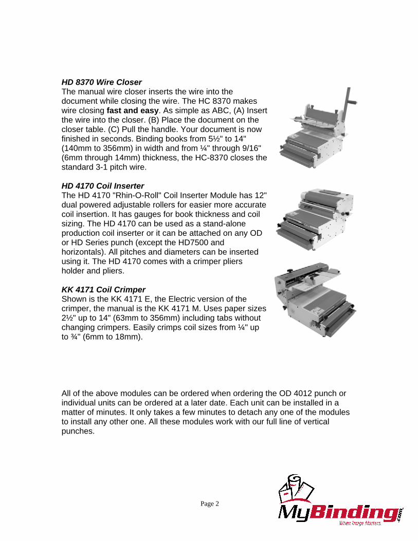
HD 8370 Wire Closer The manual wire closer inserts the wire into the document while closing the wire. The HC 8370 makes wire closing fast and easy. As simple as ABC, (A) Insert the wire into the closer. (B) Place the document on the closer table. (C) Pull the handle. Your document is now finished in seconds. Binding books from 5½" to 14" (140mm to 356mm) in width and from ¼" through 9/16" (6mm through 14mm) thickness, the HC-8370 closes the standard 3-1 pitch wire. HD 4170 Coil Inserter The HD 4170 "Rhin-O-Roll" Coil Inserter Module has 12" dual powered adjustable rollers for easier more accurate coil insertion. It has gauges for book thickness and coil sizing. The HD 4170 can be used as a stand-alone production coil inserter or it can be attached on any OD or HD Series punch (except the HD7500 and horizontals). All pitches and diameters can be inserted using it. The HD 4170 comes with a crimper pliers holder and pliers. KK 4171 Coil Crimper Shown is the KK 4171 E, the Electric version of the crimper, the manual is the KK 4171 M. Uses paper sizes 2½" up to 14" (63mm to 356mm) including tabs without changing crimpers. Easily crimps coil sizes from ¼" up to ¾" (6mm to 18mm). All of the above modules can be ordered when ordering the OD 4012 punch or individual units can be ordered at a later date. Each unit can be installed in a matter of minutes. It only takes a few minutes to detach any one of the modules to install any other one. All these modules work with our full line of vertical punches.

Page 3
Table of Contents
OD 4012 PUNCH Topic: Page Number: 1) Important safety notices 4 2) Placing your machine in the proper location 4 3) Providing power to the machine 4 4) Die installation 5
♦ Removing punch pins 5 ♦ Die maintenance 7
5) Setting the paper stop/guide 7 6) Punching Paper 8 7) Removing paper waste 8 8) Paper Jam (Reverse handle) 9 9) Attaching the Versa Switch to OD 4012 10 10) Attaching the Palm Switch to OD 4012 11 11) Troubleshooting 12 12) OD 4012 Electrical Schematics 13 13) Die List 14 Setup Illustrations Diagram 1 Die Installation 5 Diagram 2 Remove Punch Pin 5 Diagram 3 Die Maintenance 7 Diagram 4 Paper Stop/Guides 7 Comb Adjuster 8 Diagram 5 Paper Waste 8 Diagram 6 Paper Jam 9 Diagram 7 Versa Switch 10 Diagram 8 Palm Switch 11 Troubleshooting OD 4012 12 OD 4012 115VAC Schematic 13 OD 4012 230VAC Schematic 13 Die list 14

Page 4
1) Important Safety Notice! Make sure you read this section very carefully! Learn to recognize this Safety Alert Symbol.
The OD 4012 has been designed to provide a very high level of protection to an operator. Follow the guidelines below while installing, operating and maintaining your machine.
♦ Plug the machine into an outlet that provides a 15-amp service (16 amp for
European installation) that is protected at the customers’ circuit box. ♦ If machine cycles on its own, call dealer immediately for service. ♦ Never bypass top cover switch. ♦ Turn power switch off before removing a die. 2) Placing your machine in the proper location:
Before lifting machine, turn power off. Remove plug from electrical supply for your personnel safety. The machine is very heavy! Never attempt to lift machine by yourself. It needs two people to lift machine. It should be lifted at each side of the back end
and each side of the front end. Do not lift machine by the chip drawer! Place the machine on a hard level surface placing the foot pedal on the floor in front of the machine. Set aside some room for the books that have to be punched and also some room for the books that had already been punched. 3) Providing power to the machine:
Power cord shall be certified for the country where the machine will be installed. Plug one end of the power cord into the back of the machine. The other end goes into the wall outlet. Install the foot pedal plug into the receptacle, which is located on
the left side of the rear of the machine. The optional Versa Switch or Palm Switch can be plugged into the same receptacle if this option is to be used. Only one option can be used at a time.

Page 5
4) Die Installation: Diagram 1 Make sure the machine is turned off before installing die. Make sure there is no paper dust in the machine die slot before installing the die. Install the die (1) by sliding it into the opening of the machine located on the left-hand side of the machine. Make sure the punch pin retainer and pin capture slides into the slot (2) of the pusher bar. Using the two fluted knobs (3) provided with the machine, tighten each knob turning them clockwise until tight. Be sure the knobs are pulled toward the front of the machine so that the die does not interfere with the knobs threads (4).
Diagram 1

Page 6
♦ To Remove A Punch Pin From The Die: Diagram 2 Make sure the machine is turned off before removing the die. To remove a punch pin from the die, remove both fluted knobs (1) and slide the die to the left and remove. Orient die so pin retainer (2) is facing up. Remove top pin capture (3) by pushing down first, and then pulling away from bottom pin retainer to expose punch pins. If your die has the new pin pull label (4) simply pill the desired pin (5) to fit your job. Replace the pin retainer and reinstall the die using die installation procedure.
Diagram 2

Page 7
♦ Die Maintenance: Diagram 3 Make sure the machine is turned off before removing a die. To maintain the die remove from machine. Then using the oil provided with the machine, lightly squeeze oil over the oil slot (1) that runs the entire length of the die. Application of to much oil can run onto the paper being punched. After oiling, always punch scrap paper to remove excess oil.
Diagram 3
5) Setting The Paper Stop/Guides: Diagram 4 The paper stop/guide (1) is located on the top hinged cover. By loosening the knob (2) counterclockwise, the guide can be adjusted to the left or the right so the holes can be centered within the paper being punched. For 11” sheets, the right-hand portion of the guide can be set at the 11” mark (3) on the die.. When using different length sheets, the paper guide will have to be moved to a different position.
Diagram 4
Only Comb dies have an adjustable backstop. To change the position of the hole placement (margin) to the back edge of the sheet, first install the die into the OD

Page 8
4012. Pull on the black handle, which is part of the die. There are four placement positions. Choose the position best suited for your job. Pull the handle towards the left for the larger combs and push it in to the right for the smaller combs. The exact position will be left up to the operator’s preference. 6) Punching Paper: Position the paper that needs to be punched either to the left, right or on top of the machine. This is up to the individual operator. Remove 20 to 25 sheets (20lb bond copy paper, 80gsm) from the pile and slide it down vertically into the opening of the die (when punching acetate and heavier stock, punch less sheets). When the paper is fully down, slide it to the left so it comes in contact with the paper stop. Make sure all the edges of the sheets are flush by tapping the top and the right hand side of the sheets before pressing the foot pedal or pressing the palm switch. After punching the sheets, place the paper on the punched pile making sure the sheets remain in exact order. 7) Removing Paper Waste: Diagram 5 The paper waste is removed by pulling the paper waste drawer (1) up and toward you. The drawer is located conveniently in the front of the punch. Look through the clear cover while punching and empty prior to filling up and spilling into machine. When reinstalling the chip drawer back into, line up the locating pin (2) on the drawer with the slot on the machine (3).
Diagram 5

Page 9
8) Paper Jam: (Reverse knob) Diagram 6 The OD 4012 uses a circuit board for controlling its cycle and has the ability to automatically reverse the punch pins to their starting position if too much acetate or paper was inserted. There are times when punching too much acetate, the punch pins may not reverse all the way out. Use this procedure described below for manually reversing machine. When a paper jam occurs, the circuit breaker protecting the motor may
have to be reset. This is normal and allows for maximum protection for the punch motor. To reset the circuit breaker, turn the power switch off then back on. Cycle the machine. If the machine is still jammed follow the procedure below. Never
attempt to cycle machine with die partially installed in the machine. ♦ Remove Die from machine and cycle machine. If you are unable to remove
the die or cycle the machine, continue to the next step. ♦ Unplug machine from power. ♦ Remove silver safety plug (1) from machine. ♦ Push in the reverse knob (2) (that came separately with your machine). Align
with slot in motor shaft. ♦ If the punch stalled before pins were completely through the paper, turn the
reverse knob counter-clockwise (3) to reverse punch pins out of paper. ♦ If the punch stalled with the pins all the way through the paper and on its
return stroke, turn the reverse knob clockwise to continue the punch pins to there starting position.
♦ Remove reverse knob, plug machine back in. ♦ Press the foot pedal to see if the machine operates. If yes, replace the silver
safety cap and continue punching the job. If the machine does not function, see the troubleshooting section of this manual.
Diagram 6

Page 10
9) Attaching The Versa Switch To The OD 4012: Diagram 7 The Versa Switch replaces the foot pedal and paper stop/guide. By pushing the paper against this switch, it positions the paper in the correct location so the holes are centered in the sheet and also activates the punch. The Versa Switch is accessory #072180 for both 115VAC and 230VAC models.
♦ Unplug the main power cord from the OD 4012 punch. ♦ Remove the foot pedal plug from the rear or the OD 4012
punch. ♦ Install the versa switch plug into the same receptacle that the
foot pedal plug was removed from. The Versa Switch cannot be used at the same time as the foot pedal or Palm Switch covered in the next chapter.
♦ Open the top cover of the OD 4012. ♦ Remove the existing paper stop/guide from the front cover of the OD 4012 by
unscrewing the knob from the nut inside the cover. ♦ The Versa Switch comes fully assembled. The Knob (1) will have to be
removed from the assembly. Also, the BROWN and BLUE (2) wires attached to the versa switch will have to be removed. Please note where these wires were originally attached to the Versa Switch for re-assembly.
♦ Place the Switch (3) inside the Front Cover (4) and the Paper Stop (5) through the slot in the cover. Use the Knob (1) to attach the assembly back to the original configuration.
♦ Reattach the wires to the same terminals of the switch. ♦ Close and secure the front cover and replace the power cord.
Diagram 7

Page 11
10) Attaching the Palm Switch to OD 4012: Diagram 8 The Palm Switch accessory #077770 replaces the foot pedal. ♦ Unplug the main power cord from the OD 4012 punch. ♦ Remove the foot pedal plug from the rear of the OD 4012 punch. ♦ Install the Palm Switch plug into the same receptacle (1) that the foot pedal
plug was removed from. The Palm Switch cannot be used at the same time as the Foot Pedal or Versa Switch described in the previous chapter.
♦ Attach the Palm Switch Body (2) to the top of the OD 4012 as shown (3). ♦ Adjust (4) the Palm Switch so that it is comfortable to insert paper, jog, and
punch at the same time. Reattach the power cord.
Diagram 8

Page 12
11) Troubleshooting: Only Qualified Personal Should Attempt To Work On This Equipment.
The OD 4012 punch is a well-built, heavy duty punch and will give years of reliable service. Most of the problems are due to setup error. There is a circuit breaker located in the power switch at the rear of the punch that can be reset by the customer if it should trip by turning the switch off then back on. Below is a trouble shooting guide to help you through some of the problems that may be encountered.
Troubleshooting Symptom Possible Cause Action
Machine does not cycle. 1) Machine is off. 2) Machine not plugged in. 3) Foot pedal, palm switch,
or versa switch not plugged into machine.
4) Top Cover is open. 5) Circuit Breaker Tripped.
1) Check power switch. 2) Check both ends of power
cord. 3) Make sure foot pedal cable,
palm switch, or versa switch is attached to machine.
4) Close top cover. 5) Check circuit breaker switch. Switch power switch OFF then ON.
Die does not go into machine. 1) Pin retainer interference. 2) Punch stopped in mid
cycle. 3) Pins not installed properly. 4) Die locking knobs interfere
with die insertion.
1) Make sure pin retainer enters slot in pusher bar. (See diagram 1)
2) Check circuit breaker and restart machine.
3) Make sure that all the pins are flush against pin retainer.
4) Pull die locking knobs out until they stop and clear the die.
Page 13
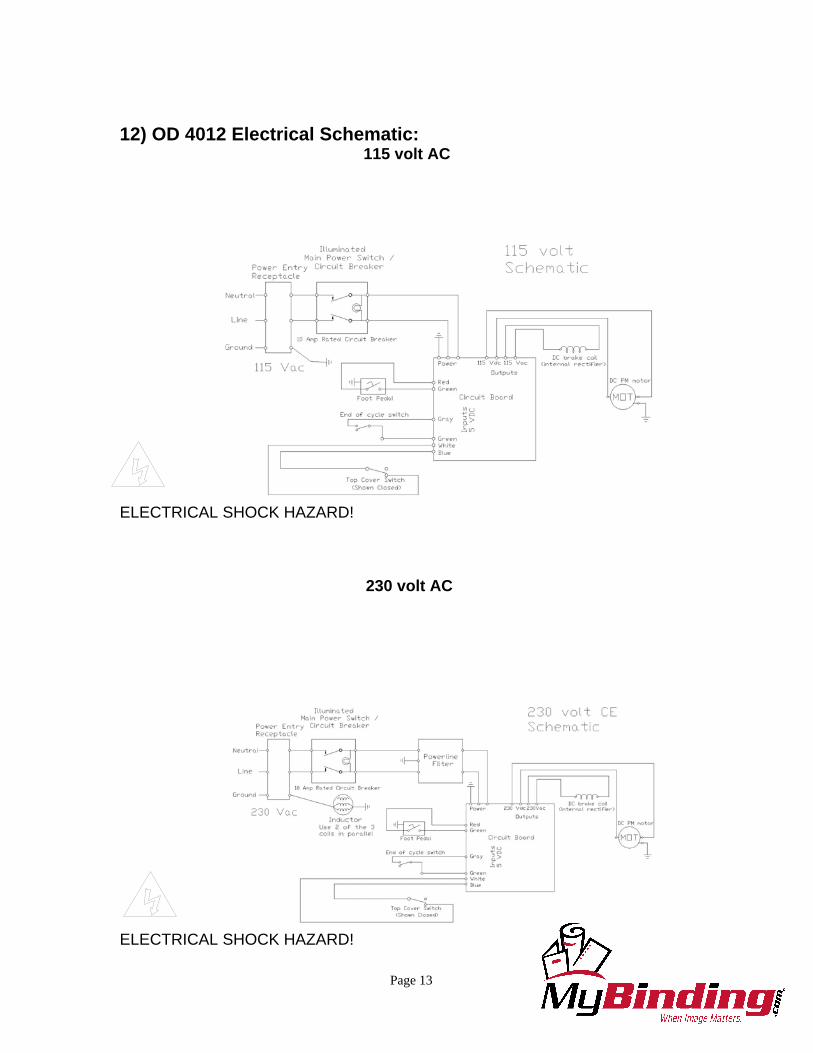
12) OD 4012 Electrical Schematic:
115 volt AC
ELECTRICAL SHOCK HAZARD!
230 volt AC
ELECTRICAL SHOCK HAZARD!

Page 14
13) Die list: This is a list of the most common dies manufactured by Performance Design. Special dies are available. Ask your dealer for more information.

IMPORTANT
Be sure to fill out and return you Product WarrantyRegistration Card inside. If you don’t find one,
please call us at 1-800-390-5782 or 1-208-384-8581.You can also register this product online at
www.RHIN-O-TUFF.com then select Warranty.
Thank You.
www.RHIN-O-TUFF.com1-800-390-5782
PART # 940120 12/04
Quality Paper Punchingand Book Binding Equipment
at Affordable Prices