Embed Size (px)
Citation preview
1
RHex - A Simple and Highly Mobile HexapodRobot
Uluc. Saranli! , Martin Buehler† and Daniel E. Koditschek!
!Department of Electrical Engineering and Computer ScienceThe University of Michigan, Ann Arbor, MI 48109-2110, USA
†Center for Intelligent MachinesMcGill University, Montreal, QC H3A 2A7, Canada
Abstract
In this paper, we describe the design and control of RHex,a power autonomous, untethered, compliant-legged hexapodrobot. RHex has only six actuators — one motor located ateach hip — achieving mechanical simplicity that promotesreliable and robust operation in real-world tasks. Empiri-cally stable and highly maneuverable locomotion arises froma very simple clock-driven, open-loop tripod gait. The legsrotate full circle, thereby preventing the common problem oftoe stubbing in the protraction (swing) phase. An extensivesuite of experimental results documents the robot’s signifi-cant ”intrinsic mobility” — the traversal of rugged, brokenand obstacle ridden ground without any terrain sensing oractively controlled adaptation. RHex achieves fast and ro-bust forward locomotion traveling at speeds up to one bodylength per second and traversing height variations well ex-ceeding its body clearance.
I. Introduction
Fig. 1. The RHex experimental platform (ai.eecs.umich.edu/RHex).
In this paper we report on a power autonomous leggedvehicle, RHex, Figure 1, that easily traverses terrain ap-proaching the complexity and diversity of the natural land-
This work is supported in part by DARPA/ONR Grant N00014-98-1-0747
TABLE I
Summary of Published Performance Reports: Hexapedal
Robot
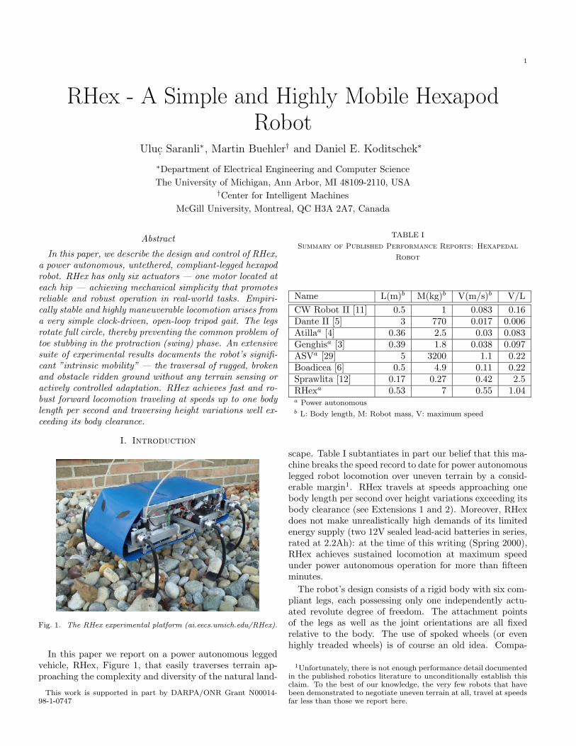
Name L(m)b M(kg)b V(m/s)b V/LCW Robot II [11] 0.5 1 0.083 0.16Dante II [5] 3 770 0.017 0.006Atillaa [4] 0.36 2.5 0.03 0.083Genghisa [3] 0.39 1.8 0.038 0.097ASVa [29] 5 3200 1.1 0.22Boadicea [6] 0.5 4.9 0.11 0.22Sprawlita [12] 0.17 0.27 0.42 2.5RHexa 0.53 7 0.55 1.04a Power autonomousb L: Body length, M: Robot mass, V: maximum speed
scape. Table I subtantiates in part our belief that this ma-chine breaks the speed record to date for power autonomouslegged robot locomotion over uneven terrain by a consid-erable margin1. RHex travels at speeds approaching onebody length per second over height variations exceeding itsbody clearance (see Extensions 1 and 2). Moreover, RHexdoes not make unrealistically high demands of its limitedenergy supply (two 12V sealed lead-acid batteries in series,rated at 2.2Ah): at the time of this writing (Spring 2000),RHex achieves sustained locomotion at maximum speedunder power autonomous operation for more than fifteenminutes.
The robot’s design consists of a rigid body with six com-pliant legs, each possessing only one independently actu-ated revolute degree of freedom. The attachment pointsof the legs as well as the joint orientations are all fixedrelative to the body. The use of spoked wheels (or evenhighly treaded wheels) is of course an old idea. Compa-
1Unfortunately, there is not enough performance detail documentedin the published robotics literature to unconditionally establish thisclaim. To the best of our knowledge, the very few robots that havebeen demonstrated to negotiate uneven terrain at all, travel at speedsfar less than those we report here.

2
rable morphologies such as rimless wheels [13] or singlespoked wheels [22] have been previously proposed for mo-bile platforms. Some compliant legged designs have beenproposed for toys [20], and some rigid rimless wheeled de-signs have actually been commercialized by the toy indus-try [26]. However, the major di!erence between a singleleg and a wheel with more than two spokes arises fromthe far greater range of control over the ground reactionforces (GRF) that the former a!ords relative to the latter.Wheels a!ord control primarily over the horizontal compo-nent of the GRF (assuming flat ground) through friction,incurring an essentially uncontrolled concomittant verticalcomponent. In contrast, a leg, by admitting selection overthe angle of contact, yields a GRF whose direction as wellas magnitude may be substantially controlled. As soon asmultiple spokes are added, the inter-spoke angle restrictsthe range of contact angles, thereby diminishing control af-fordance. Our design preserves the possiblity of achievingfull GRF range while adding the virtues of tuned compli-ance, heretofore associated only with wheels.
Fig. 2. Comparative views of locomotion in the rough: the cockroachBlaberus discoidalis (top photo, courtesy of R. J. Full [14]) runsat 3.7 body lengths ("24 cm) per second [15], whereas RHex(bottom photo) presently runs at only one body length ("50 cm)per second over comparably scaled broken terrain (see Extensions3 and 4).
The closest extant robots, one significant source of inspi-ration for the RHex design, are the second author’s Scoutclass quadrupeds (www.cim.mcgill.ca/˜arlweb) [9, 10, 28]that also feature compliant legs, and reduce mechanical
complexity by the restriction of one actuator per leg2. Thecentral di!erence with respect to this design is the pos-sibility of recirculating — i.e., treating the singly actu-ated leg as a single spoked “rimless wheel”. A second keydesign influence whose careful consideration exceeds thescope of this paper arises from biomechanics. R.J. Full’svideo of a Blaberus cockroach racing seemingly e!ortlesslyover the rough surface illustrated in Figure 2, was shownat an interdisciplinary meeting [27] motivating and initi-ating the development of RHex. The present design maybe seen as instantiating the notion of a “preflex” [8] —implemented here in the clock driven mechanically self sta-bilizing compliant sprawled posture mechanics that Fullproposed3 [15]. The notion of a “clock driven” mechanismarises in our choice of an controller to derive appropriateadvantage of RHex’s mechanical design. At the time ofthis writing, RHex operates by tracking (via local PD con-tol) at each hip joint a copy of the reference trajectory de-picted in Figure 4 that enforces an alternating tripod gaitin an otherwise open loop manner. The two tripods aredriven in relative antiphase. The three legs of a tripod aredriven simultaneously through a slow “retraction” phase,putatively corresponding to ground contact, followed by afast “protraction” phase designed to recirculate the legsaway from the the ground around the axle just in time toreach the next “retraction” phase, putatively as the oppos-ing tripod begins its “protraction” by rotating away fromground contact. No design we are aware of has heretoforeincorporated this combination of controller simplicity, legcompliance, limited actuation and overall morphology, andno previously implemented legged vehicle has achieved theperformance we now report.
Table I (modeled on, but extended from [6]) summarizesperformance data for previous hexapedal vehicles respect-ing which we are aware of documented performance, withcitations to refereed publications. It would be of consid-erable interest to compare across a broader range of ma-chines. Unfortunately, it is not straightforward to normal-ize against morphology. For example, “body lengths persecond” is clearly not an appropriately normalized mea-sure of bipedal speed. We look forward to the eventualadoption of appropriately general performance metrics forlegged locomotion within the robotics research community.For the present, it seems most useful to compare the designof RHex with some of its more closely related forebears.
One of the better documented, faster, power autonomoushexapods, the OSU adaptive suspension vehicle (ASV) wasdesigned to operate in the statically stable regime. Thedeleterious consequences of design complexity have beenobserved in Dante II [5], a tethered hexapod whose expo-sure to severe environmental conditions have apparentlybeen the most extreme of any robot yet documented in the
2Scout II travels at just under two bodylengths per second, buttraverses only level ground.
3See [2] for a technical discussion of some aspects relating the bioin-spiration behind this design to its performance.

3
archival literature. On a smaller scale, there have beenmany platforms inspired by insect locomotion [3, 4, 6], alldesigned for statically stable gaits. Their speeds were thuslimited even though their design a!orded greater kinematicfreedom over limb motions. A notable exception in thesmaller scale is Sprawlita [12], a tethered hexapod whichcan achieve a very impressive 2.5 body lengths per sec-ond locomotion speed as a result of its careful (compliantleg) design, and construction (o!board pneumatic actua-tion and small size).
For most of these machines, rough terrain performanceand obstacle crossing capabilities are not carefully docu-mented in the literature. There are only a few exampleswhere such capabilities are reported in detail [5, 29], buteven these are not suitable for assessing relative perfor-mance due to di!erences in scale and the lack of a consis-tent set of experiments and measures. Without more or lessuniform standards of reporting, it becomes very di"cult totest the claim that the relative speed (we use body lengthsper second), relative endurance (we use specific resistancebut also provide actual run-time data as well), relative mo-bility (we provide a metric characterization of the variousterrain features) of one design is superior to another. Thus,beyond the specifics of design and performance, we believethat the paper makes a distinct contribution to the roboticsliterature by establishing new standards of rigor in empir-ical performance reporting for legged vehicles.
In summary, we believe this new design opens up a largerange of new possibilities for control of locomotion, whilestill meeting the constraints imposed by contemporary ac-tuation and energy storage technology on engineering au-tonomous robotic platforms. At the present time, we areunable to provide a mathematically informed analysis ofhow and why RHex performs over the range of reportedbehaviors. Instead, in this first archival paper, we presentcareful empirical documentation of a narrow but very use-ful behavioral suite — a base range of locomotion capa-bilities at relatively high speeds over relatively challengingterrain — and observe that no other power autonomouslegged design has ever before been demonstrated to exhibita comparable breadth of mobility behaviors.
II. Design and Modeling
A. Design Concept and Morphology
In all robotics applications, mechanical complexity is oneof the major sources of failure and considerably increasesthe cost. Our design emphasizes mechanical simplicity andthereby promotes robustness. Autonomy, a critical com-ponent of our aspiration toward real-world tasks in un-structured environments outside the laboratory, imposesvery strict design constraints on the hardware and soft-ware components. It is often impossible to achieve withsimple modifications to a system otherwise designed fornon-autonomous operation. These constraints also justifyour preference for overall simplicity — in particular towards
minimizing the amount of actuation and limited reliance onsensing.
Our design, depicted in Figure 3, consists of a rigid bodywith six compliant legs, each possessing only one indepen-dently actuated revolute degree of freedom. The attach-ment points of the legs as well as the joint orientations areall fixed relative to the body.
xy
z
ai
fi
rb
B
W!i
"i#i
Fig. 3. The compliant hexapod design.
This configuration admits an alternating tripod gait forforward and backward locomotion, and possibly other moreelaborate behaviors such as leaping, stair climbing etc.Moreover, the symmetry of this idealized model allowsidentical upside-down operation and imposes no restric-tions on forward directionality. We explore some of thisbehavioral repertoire both in simulation and experimen-tally in Section IV and Section V, respectively.
B. The Compliant Hexapod Model
In this section, we present a dynamical model of themorphology described in the previous section. Prior tothe construction of the experimental prototype, this modelenabled us to assess the viability of the design throughsimulation studies. Augmented with the actuator modelof Section IV-A, it proved to be an invaluable tool in thedesign process.
Two reference frames, B and W are defined in Figure 3,the former attached to the hexapod body and the latter aninertial frame where the dynamics are formulated. In B, wedefine the +y direction to be forward and the +x directionto be the the right side of the robot. The position andorientation of the rigid body are described by rb ! R3 andRb ! SO(3), respectively, expressed in W. Table II detailsthe notation used throughout the paper.
Each leg is assumed to be massless and has three de-grees of freedom. The leg state is described in sphericalcoordinates [!i,"i, #i]T whose origin is at ai in the bodyframe4.
4Note that (rb,Rb), vi and fi are related through the coordinatetransformation #Rb(ai + vi) = fi + rb
4
TABLE II
Notation
Statesrb, Rb body position and orientation$ body yaw angle
Leg states and parametersai leg attachment point in Bfi toe position in Wvi := [!i,"i, #i]T
leg state in spherical coordinatesvi := [vxi , vyi , vzi ]T
leg state in cartesian coordinateslegi stance flag for leg i
Forces and TorquesFri radial leg spring force%!i bend torque in !i direction%"i hip torque in "i direction
Controller Parameterstc period of rotation for a single legts duration of slow leg swing"s leg sweep angle for slow leg swing"o leg angle o!setu := [tc, ts,"s,"o] control vector#"o di!erential change in "o for turning#ts di!erential change in ts for turning.
B.1 Equations of Motion
Our formulation of the equations of motion for thehexapod model is based on individually incorporating theground reaction forces at each leg. To this end, it will suf-fice to analyze a generic leg parametrized by its attachmentand touchdown points, ai and fi, respectively. As a con-sequence of the assumption that the leg is massless, therigid body experiences the ground reaction force on theleg, resulting in e!ective force and torque vectors actingon the center of mass. For each leg i = 1, ..., 6, followingprojections on B, we have,
Fi =
!
"
" cos !i sin"i sin !i sin"i " cos "i
sin !i cos !i 0cos !i cos "i " sin !i cos "i " sin "i
#
$ .
!
"
Fri
%!i/#i
%"i/(#i cos !i)
#
$
%i = (vi + ai) # Fi
which are the force and torque contributions of a sin-gle leg to the overall system dynamics, respectively. Thecumulative e!ect of all the legs on the body is simply thesum of the individual contributions from the legs in contactwith the ground, together with the gravitational force.
FT =%
0 0 "mg&T + Rb
6'
i=1
legiFi (1)
%T = Rb
6'
i=1
legi%i (2)
(3)
The contact states of the legs are indicated by legi. Inconsequence, the dynamics of the hexapod are governed bythe standard rigid body dynamics under external torqueand force inputs [18]. Note also that, the discrete tran-sitions in the contact states of the legs result in a hybriddynamical system, whose behavior can be substantially dif-ferent than that of its continuous constituents alone.
III. Control Strategy
The present prototype robot has no external sensors bywhich its body state may be estimated. Thus, in our sim-ulations and experiments, we have used joint space closedloop (“proprioceptive”) but task space open loop controlstrategies. The algorithms that we describe in this sec-tion are tailored to demonstrate the intrinsic reliability ofthe compliant hexapod morphology and emphasize its abil-ity to operate without a sensor-rich environment. Specif-ically, we present a four-parameter family of controllers,that yields translation and turning of the hexapod on flatterrain, without explicit enforcement of quasi-static stabil-ity. In Section V-C, we demonstrate the capabilities of thisfamily of controllers on our experimental platform, overa wide range of terrain conditions, from flat terrain to arough, broken surface.
All controllers generate periodic desired trajectories foreach hip joint, which are then enforced by six local PDcontrollers (one for each individual hip actuator). In thisrespect, the present controller family represents one near-extreme along the spectrum of possible control strategies,ranging from purely feedforward (i.e., taking no notice ofbody state), to purely feedback (i.e., producing torquesolely in reaction to leg and rigid body state). It seemslikely that neither one of these extremes is best and a com-bination should be adopted. The simulations and experi-ments presented in this paper attempt to characterize theproperties associated with the sensorless feedforward ex-treme, which, when RHex has been endowed with sensors,we hope to complement with feedback to explore the afore-mentioned range.
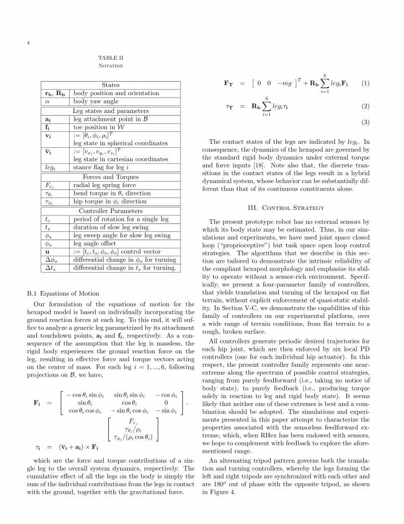
An alternating tripod pattern governs both the transla-tion and turning controllers, whereby the legs forming theleft and right tripods are synchronized with each other andare 180o out of phase with the opposite tripod, as shownin Figure 4.
5
Fig. 4. The motion profiles for left and right tripods.
A. The Forward Alternating Tripod Gait
The open loop controller’s target trajectories for eachtripod are periodic functions of time, parametrized by fourvariables: tc, ts, "s and "o. In a single cycle, both tripodsgo through slow and fast swing phases, covering "s and2& " "s of the complete rotation, respectively. The periodof both profiles is tc. In conjunction with ts, it determinesthe duty factor of each tripod, with respect to the durationof their slow and fast phases. The time of “double support”td (where all six legs are in their slow phases, but possiblynot all of them touching the ground) is hence determined bythe duty factors of both tripods. Finally, the "o parametero!sets the motion profile with respect to the vertical (seeFigure 4). Note that both profiles are illustrated to bemonotonically increasing in time; but they can be negatedto obtain backward locomotion.
Control of locomotion is achieved by modifying theseparameters for a particular desired behavior during loco-motion. In Section IV, our simulation studies reveal cor-relations of these parameters with certain behavioral at-tributes.
B. Turning
We have developed two di!erent controllers for two quali-tatively di!erent turning modes: turning in place and turn-ing during translation. These controllers are inspired bydi!erential turning in wheeled and tracked vehicles, whereopposite perturbations to contralateral actuators result ina net rotation of the body on the plane. Analytical un-derstanding of this behavior in the context of our designawaits careful mathematical treatment of RHex’s dynamicsas well as accurate models of ground contact.
The controller for turning in place employs the same legprofiles as for forward locomotion except that contralateralsets of legs rotate in opposite directions. This results in thehexapod turning in place in the direction determined by the
rotational polarity of the left and right sets of legs. Notethat the tripods are still synchronized internally, maintain-ing three supporting legs on the ground. Similar to thecontrol of the forward locomotion speed, the rate of turningdepends on the choice of the particular motion parameters,mainly tc and "s.
In contrast, we achieve turning during forward locomo-tion by introducing di!erential perturbations to the for-ward running controller parameters for contralateral legs.In this scheme, tc is still constrained to be identical forall legs, which admits di!erentials in the remaining profileparameters, "o and ts, while "s remains unchanged. Twonew gain parameters, #ts and #"o are introduced. Turn-ing right (towards +x in the coordinate system of Figure 3,defining +y as forward) is achieved by using ul = [tc, ts +#ts,"s,"o +#"o] and ur = [tc, ts "#ts,"s,"o "#"o] forthe legs on the left and right sides, respectively.
IV. Simulation Studies
Our simulation studies in this section use the dynamicalmodel described in Section II-B, together with an actuatormodel to demonstrate the feasibility of basic locomotionbehaviors of our design under practical actuation limita-tions. The presented results provide a proof of concept forthe design, justifying the building of our prototype and theextensive experiments of later sections. In order to limitthe scope of the paper to an appropriate length, however,we have excluded impact of these models and the resultingsimulation tools in refining the kinematic and dynamicalparameters of our experimental prototype.
A. Actuator Model
The model of Section II-B does not impose any con-straints on the choice of the hip torques %"i . In practice,however, torque limitations are one of the major challengesin the design of autonomous legged vehicles, even for stat-ically stable modes of operation. In order to capture thisaspect of our design space in the subsequent simulationstudies, we incorporate a simple model of the hip actua-tion.
−1 −0.5 0 0.5 1x 10⁴
−200
−100
0
100
200
Fig. 5. Torque characteristics for the Maxon RE118751 20WDC motor, reproduced from the manufacturer’s datasheet. Theshaded band illustrates the range of torque deliverable by the mo-tor.
6
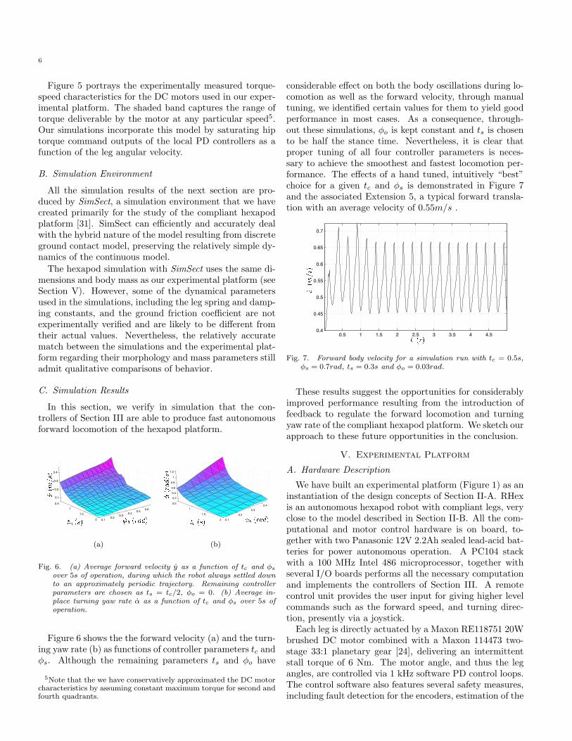
Figure 5 portrays the experimentally measured torque-speed characteristics for the DC motors used in our exper-imental platform. The shaded band captures the range oftorque deliverable by the motor at any particular speed5.Our simulations incorporate this model by saturating hiptorque command outputs of the local PD controllers as afunction of the leg angular velocity.
B. Simulation Environment
All the simulation results of the next section are pro-duced by SimSect, a simulation environment that we havecreated primarily for the study of the compliant hexapodplatform [31]. SimSect can e"ciently and accurately dealwith the hybrid nature of the model resulting from discreteground contact model, preserving the relatively simple dy-namics of the continuous model.
The hexapod simulation with SimSect uses the same di-mensions and body mass as our experimental platform (seeSection V). However, some of the dynamical parametersused in the simulations, including the leg spring and damp-ing constants, and the ground friction coe"cient are notexperimentally verified and are likely to be di!erent fromtheir actual values. Nevertheless, the relatively accuratematch between the simulations and the experimental plat-form regarding their morphology and mass parameters stilladmit qualitative comparisons of behavior.
C. Simulation Results
In this section, we verify in simulation that the con-trollers of Section III are able to produce fast autonomousforward locomotion of the hexapod platform.
0.51
1.5
2 0.10.2
0.3 0.4 0.5 0.6
0.1
0.2
0.3
0.4
(a)
0.5
1
1.5
2 0.1
0.20.3
0.4
0.2
0.4
0.6
0.8
1
1.2
(b)
Fig. 6. (a) Average forward velocity y as a function of tc and !s
over 5s of operation, during which the robot always settled downto an approximately periodic trajectory. Remaining controllerparameters are chosen as ts = tc/2, !o = 0. (b) Average in-place turning yaw rate " as a function of tc and !s over 5s ofoperation.
Figure 6 shows the the forward velocity (a) and the turn-ing yaw rate (b) as functions of controller parameters tc and"s. Although the remaining parameters ts and "o have
5Note that the we have conservatively approximated the DC motorcharacteristics by assuming constant maximum torque for second andfourth quadrants.
considerable e!ect on both the body oscillations during lo-comotion as well as the forward velocity, through manualtuning, we identified certain values for them to yield goodperformance in most cases. As a consequence, through-out these simulations, "o is kept constant and ts is chosento be half the stance time. Nevertheless, it is clear thatproper tuning of all four controller parameters is neces-sary to achieve the smoothest and fastest locomotion per-formance. The e!ects of a hand tuned, intuitively “best”choice for a given tc and "s is demonstrated in Figure 7and the associated Extension 5, a typical forward transla-tion with an average velocity of 0.55m/s .
0.5 1 1.5 2 2.5 3 3.5 4 4.50.4
0.45
0.5
0.55
0.6
0.65
0.7
Fig. 7. Forward body velocity for a simulation run with tc = 0.5s,!s = 0.7rad, ts = 0.3s and !o = 0.03rad.
These results suggest the opportunities for considerablyimproved performance resulting from the introduction offeedback to regulate the forward locomotion and turningyaw rate of the compliant hexapod platform. We sketch ourapproach to these future opportunities in the conclusion.
V. Experimental Platform
A. Hardware Description
We have built an experimental platform (Figure 1) as aninstantiation of the design concepts of Section II-A. RHexis an autonomous hexapod robot with compliant legs, veryclose to the model described in Section II-B. All the com-putational and motor control hardware is on board, to-gether with two Panasonic 12V 2.2Ah sealed lead-acid bat-teries for power autonomous operation. A PC104 stackwith a 100 MHz Intel 486 microprocessor, together withseveral I/O boards performs all the necessary computationand implements the controllers of Section III. A remotecontrol unit provides the user input for giving higher levelcommands such as the forward speed, and turning direc-tion, presently via a joystick.
Each leg is directly actuated by a Maxon RE118751 20Wbrushed DC motor combined with a Maxon 114473 two-stage 33:1 planetary gear [24], delivering an intermittentstall torque of 6 Nm. The motor angle, and thus the legangles, are controlled via 1 kHz software PD control loops.The control software also features several safety measures,including fault detection for the encoders, estimation of the
7
rotor temperatures to avoid motor damage, and a watchdogtimer which disables the motors and resets the computerin case of software failures.
The main body measures 53x20x15 cm, and roughlymatches the symmetries of the ideal model, except for theslightly lower center of mass and the larger length of thebottom side. The legs are made from 1 cm diameter Del-rin rods and are “C” shaped to increase compliance in theradial direction and permit easy clamping to the gear shaft(see Extension 6). The leg length is 17.5 cm, measured asthe vertical distance from ground to the gear shaft whenstanding up. We experimentally measured their compli-ance to be approximately 4500 N/m in their expected op-erating region. The encoder/motor/gear stacks protrudefrom the main body and the maximum widths of the frontand back legs amount to 39.4 cm, measured at half theleg length. To provide clearance for the rotating front andback legs, the motors for the middle legs are further o!-set and result in a maximum width of 52 cm. The totalmass of the robot is 7 kg with each leg contributing onlyapproximately 10 g.
B. Visual Measurement Apparatus
Absent any inertial sensing on RHex, we devised a simplevisual tracking system to record the robot’s position andorientation in the sagittal (obstacle crossing experiments)and the horizontal (turning and rough surface experiment)planes. Four Light Emitting Diodes (LEDs) were attachedto the robot’s body and a set of stationary calibration LEDswere placed close to the extremes of the camera’s field ofview. The experiments were then conducted in completedarkness, which provided for very high contrast recordingsof the LED markers. Thanks to this greatly simplified vi-sual data, standard computer vision algorithms were thenemployed to extract the planar robot position and orienta-tion up to a 1% accuracy in the average velocity computa-tions.
C. Experimental Results
In the sequel, we will document the robot’s speed overvarious terrains, its maneuverability, obstacle crossing ca-pability, and payload. Furthermore, energy e"ciency andruntime are critical performance criteria for any unteth-ered robot. Thus the energetic performance of the robotis carefully documented, but it must be noted that at thetime of this writing, no e!orts have been made to opti-mize it. All experiments — except the random obstaclesexperiment, Figure 12, Section B-D — were run untetheredand we document the average power consumption, basedon recordings of the battery voltage and current.
To measure energy e"ciency we use the “Specific Re-sistance” [17], ' = P/(mgv), based on the robot’s weight,mg, and its average power consumption, P , at a particularspeed, v. Specific resistance was originally used to comparethe energy e"ciency of animals of vastly di!erent sizes,
TABLE III
Experimental statistics
carp
et
linol
eum
gras
s
grav
el
rough
singl
eob
st.
com
p.
const
.
obst
.co
urs
e
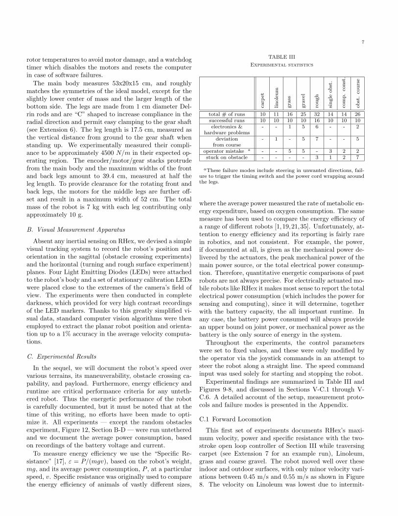
total # of runs 10 11 16 25 32 14 14 26successful runs 10 10 10 10 16 10 10 10electronics & - - 1 5 6 - - 2
hardware problemsdeviation - 1 - 5 7 - - 5
from courseoperator mistake a - - 5 5 - 3 2 2stuck on obstacle - - - - 3 1 2 7
aThese failure modes include steering in unwanted directions, fail-ure to trigger the timing switch and the power cord wrapping aroundthe legs.
where the average power measured the rate of metabolic en-ergy expenditure, based on oxygen consumption. The samemeasure has been used to compare the energy e"ciency ofa range of di!erent robots [1,19,21,35]. Unfortunately, at-tention to energy e"ciency and its reporting is fairly rarein robotics, and not consistent. For example, the power,if documented at all, is given as the mechanical power de-livered by the actuators, the peak mechanical power of themain power source, or the total electrical power consump-tion. Therefore, quantitative energetic comparisons of pastrobots are not always precise. For electrically actuated mo-bile robots like RHex it makes most sense to report the totalelectrical power consumption (which includes the power forsensing and computing), since it will determine, togetherwith the battery capacity, the all important runtime. Inany case, the battery power consumed will always providean upper bound on joint power, or mechanical power as thebattery is the only source of energy in the system.
Throughout the experiments, the control parameterswere set to fixed values, and these were only modified bythe operator via the joystick commands in an attempt tosteer the robot along a straight line. The speed commandinput was used solely for starting and stopping the robot.
Experimental findings are summarized in Table III andFigures 9-8, and discussed in Sections V-C.1 through V-C.6. A detailed account of the setup, measurement proto-cols and failure modes is presented in the Appendix.
C.1 Forward Locomotion
This first set of experiments documents RHex’s maxi-mum velocity, power and specific resistance with the two-stroke open loop controller of Section III while traversingcarpet (see Extension 7 for an example run), Linoleum,grass and coarse gravel. The robot moved well over theseindoor and outdoor surfaces, with only minor velocity vari-ations between 0.45 m/s and 0.55 m/s as shown in Figure8. The velocity on Linoleum was lowest due to intermit-

8
tent slipping, which also causes a larger standard deviationof the runs compared to carpet. In the current prototype,the relatively high natural frequency of the system and theopen loop nature of the leg trajectories limit the maximumspeed due to out of phase vertical body oscillations, whichreduce traction. The surface irregularities of the outdoorgrass and gravel surfaces provided improved traction, andtherefore average velocities slightly above 0.5 m/s, but alsoresulted in larger variations between the runs. The specificresistance (power consumption) was lowest on carpet with2.21 (80 W) and highest on gravel with 3.74 (140 W). Weexperimented with control parameter settings to reach themaximum robot velocity on o"ce carpet and linoleum, andselected u = [0.45, 0.2, 51, 0]. The grass and gravel surfaceswere not tested with these settings prior to the reportedexperiments. Figure 8 shows the average velocity, powerconsumption and the specific resistance over ten runs, withstandard deviations for all the experiments. All the exper-imental data as well as the associated analysis scripts canalso be found in Extension 8. Table III summarizes the fail-ure modes and statistics for all the experiments describedin this Section.
carpetlinoleumgrassgravelroughobst. coursepayload
0.2 0.25 0.3 0.35 0.4 0.45 0.5 0.55 0.6Average forward velocity (m/s)
carpetlinoleumgrassgravelroughobst. coursepayload
80 100 120 140 160 180 200 220 240 260Average power consumption (W)
carpetlinoleumgrassgravelroughobst. coursepayload
2 4 6 8 10 12Average specific resistance
Fig. 8. Comparison of average forward velocity and energetics fordi!erent experiments (also see Extension 8).
C.2 Turning
As our simulation study had predicted, steering is pos-sible, even though the leg actuation is limited to motionin the sagittal plane only, via di!erential motion betweenleft and right legs. We selected control parameters which
TABLE IV
Controller parameters for turning at different speeds
x tc ts "s "o #"o #ts(m/s) (s) (s) (rad) (rad) (rad) (s)
0 1.0 0.6 35 0.0 0.0 0.00.16 1.2 0.7 25 0.0 6.0 "0.020.28 0.8 0.45 35 0.0 7.5 0.00.39 0.53 0.33 40 0.0 6.5 0.0
resulted in turns in place and robot speeds up to about 0.4m/s (see Table IV) on most flat surfaces including carpet,linoleum, grass and gravel. The maximum forward veloc-ity is reduced during turning, because the di!erential legmotion precipitates the onset of the speed limiting verticalbody oscillations. The maximum yaw angular velocitiesincrease almost linearly with forward velocity up to 0.19rad/s at 0.39 m/s, as illustrated in Figure 9. Interestingly,the resulting turn radius is almost constant with approx-imately 2 m. Turning in place provides the highest yawangular velocity of 0.7 rad/s, although it is not possibleto directly compare its performance to di!erential turning,which is a qualitatively di!erent controller. At present, wedo not understand completely the relationship between thecontroller parameters and e!ective yaw rates, a subject ofongoing research.
C.3 Obstacle Crossing
0.005 0.16 0.28 0.39
0.082
0.13
0.19
0.7
Fig. 9. Turning yaw rateas a function of forwardvelocity. See Extension9 for all the data andanalysis scripts associ-ated with the turning ex-periments.
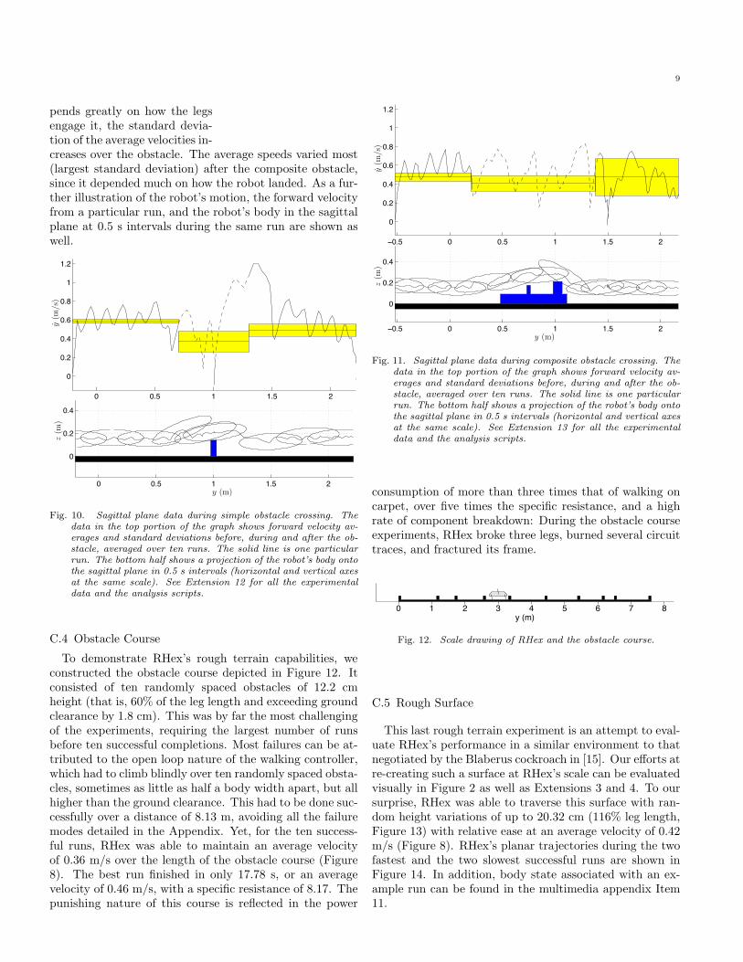
The obstacle crossing capa-bilities of the simple open loopwalking controller were eval-uated with two di!erent ob-stacles - a 15 cm high Sty-rofoam block and a compos-ite obstacle with a maximumheight of 22 cm, as shown inFigures 10 and 11, respectively(also see Extensions 10 and11). The robot was able tosurmount both obstacles, nei-ther sensing them, nor withany modification to the con-trol parameters of the walkingexperiments. The data in thetop portions of the two graphsshows the forward velocity av-erages before, during and afterthe obstacle, averaged over tenruns. Surprisingly, the averagevelocity decreases only slightlyas the robot climbs over the ob-stacle, and increases again af-terwards. Since the robot’s tra-jectory over the obstacle de-
9
pends greatly on how the legsengage it, the standard devia-tion of the average velocities in-creases over the obstacle. The average speeds varied most(largest standard deviation) after the composite obstacle,since it depended much on how the robot landed. As a fur-ther illustration of the robot’s motion, the forward velocityfrom a particular run, and the robot’s body in the sagittalplane at 0.5 s intervals during the same run are shown aswell.
0 0.5 1 1.5 2
0
0.2
0.4
0.6
0.8
1
1.2
0 0.5 1 1.5 2
0
0.2
0.4
y(m
/s)
y (m)
z(m
)
Fig. 10. Sagittal plane data during simple obstacle crossing. Thedata in the top portion of the graph shows forward velocity av-erages and standard deviations before, during and after the ob-stacle, averaged over ten runs. The solid line is one particularrun. The bottom half shows a projection of the robot’s body ontothe sagittal plane in 0.5 s intervals (horizontal and vertical axesat the same scale). See Extension 12 for all the experimentaldata and the analysis scripts.
C.4 Obstacle Course
To demonstrate RHex’s rough terrain capabilities, weconstructed the obstacle course depicted in Figure 12. Itconsisted of ten randomly spaced obstacles of 12.2 cmheight (that is, 60% of the leg length and exceeding groundclearance by 1.8 cm). This was by far the most challengingof the experiments, requiring the largest number of runsbefore ten successful completions. Most failures can be at-tributed to the open loop nature of the walking controller,which had to climb blindly over ten randomly spaced obsta-cles, sometimes as little as half a body width apart, but allhigher than the ground clearance. This had to be done suc-cessfully over a distance of 8.13 m, avoiding all the failuremodes detailed in the Appendix. Yet, for the ten success-ful runs, RHex was able to maintain an average velocityof 0.36 m/s over the length of the obstacle course (Figure8). The best run finished in only 17.78 s, or an averagevelocity of 0.46 m/s, with a specific resistance of 8.17. Thepunishing nature of this course is reflected in the power
−0.5 0 0.5 1 1.5 2
0
0.2
0.4
0.6
0.8
1
1.2
−0.5 0 0.5 1 1.5 2
0
0.2
0.4
y(m
/s)
y (m)
z(m
)
Fig. 11. Sagittal plane data during composite obstacle crossing. Thedata in the top portion of the graph shows forward velocity av-erages and standard deviations before, during and after the ob-stacle, averaged over ten runs. The solid line is one particularrun. The bottom half shows a projection of the robot’s body ontothe sagittal plane in 0.5 s intervals (horizontal and vertical axesat the same scale). See Extension 13 for all the experimentaldata and the analysis scripts.
consumption of more than three times that of walking oncarpet, over five times the specific resistance, and a highrate of component breakdown: During the obstacle courseexperiments, RHex broke three legs, burned several circuittraces, and fractured its frame.
0 1 2 3 4 5 6 7 8y (m)
Fig. 12. Scale drawing of RHex and the obstacle course.
C.5 Rough Surface
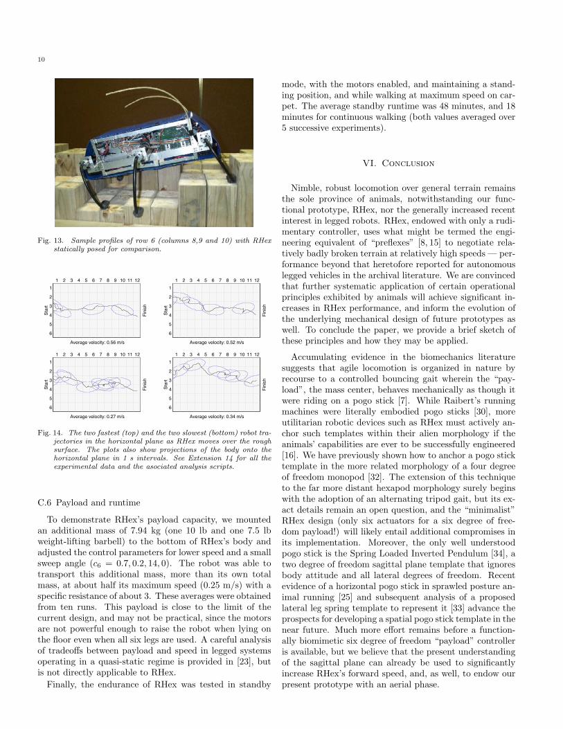
This last rough terrain experiment is an attempt to eval-uate RHex’s performance in a similar environment to thatnegotiated by the Blaberus cockroach in [15]. Our e!orts atre-creating such a surface at RHex’s scale can be evaluatedvisually in Figure 2 as well as Extensions 3 and 4. To oursurprise, RHex was able to traverse this surface with ran-dom height variations of up to 20.32 cm (116% leg length,Figure 13) with relative ease at an average velocity of 0.42m/s (Figure 8). RHex’s planar trajectories during the twofastest and the two slowest successful runs are shown inFigure 14. In addition, body state associated with an ex-ample run can be found in the multimedia appendix Item11.
10
Fig. 13. Sample profiles of row 6 (columns 8,9 and 10) with RHexstatically posed for comparison.
1 2 3 4 5 6 7 8 9 10 11 121
2
3
4
5
6
Average velocity: 0.56 m/s
Star
t
Fini
sh
1 2 3 4 5 6 7 8 9 10 11 121
2
3
4
5
6
Average velocity: 0.52 m/s
Star
t
Fini
sh
1 2 3 4 5 6 7 8 9 10 11 121
2
3
4
5
6
Average velocity: 0.27 m/s
Star
t
Fini
sh
1 2 3 4 5 6 7 8 9 10 11 121
2
3
4
5
6
Average velocity: 0.34 m/s
Star
t
Fini
sh
Fig. 14. The two fastest (top) and the two slowest (bottom) robot tra-jectories in the horizontal plane as RHex moves over the roughsurface. The plots also show projections of the body onto thehorizontal plane in 1 s intervals. See Extension 14 for all theexperimental data and the asociated analysis scripts.
C.6 Payload and runtime
To demonstrate RHex’s payload capacity, we mountedan additional mass of 7.94 kg (one 10 lb and one 7.5 lbweight-lifting barbell) to the bottom of RHex’s body andadjusted the control parameters for lower speed and a smallsweep angle (c6 = 0.7, 0.2, 14, 0). The robot was able totransport this additional mass, more than its own totalmass, at about half its maximum speed (0.25 m/s) with aspecific resistance of about 3. These averages were obtainedfrom ten runs. This payload is close to the limit of thecurrent design, and may not be practical, since the motorsare not powerful enough to raise the robot when lying onthe floor even when all six legs are used. A careful analysisof tradeo!s between payload and speed in legged systemsoperating in a quasi-static regime is provided in [23], butis not directly applicable to RHex.
Finally, the endurance of RHex was tested in standby
mode, with the motors enabled, and maintaining a stand-ing position, and while walking at maximum speed on car-pet. The average standby runtime was 48 minutes, and 18minutes for continuous walking (both values averaged over5 successive experiments).
VI. Conclusion
Nimble, robust locomotion over general terrain remainsthe sole province of animals, notwithstanding our func-tional prototype, RHex, nor the generally increased recentinterest in legged robots. RHex, endowed with only a rudi-mentary controller, uses what might be termed the engi-neering equivalent of “preflexes” [8, 15] to negotiate rela-tively badly broken terrain at relatively high speeds — per-formance beyond that heretofore reported for autonomouslegged vehicles in the archival literature. We are convincedthat further systematic application of certain operationalprinciples exhibited by animals will achieve significant in-creases in RHex performance, and inform the evolution ofthe underlying mechanical design of future prototypes aswell. To conclude the paper, we provide a brief sketch ofthese principles and how they may be applied.
Accumulating evidence in the biomechanics literaturesuggests that agile locomotion is organized in nature byrecourse to a controlled bouncing gait wherein the “pay-load”, the mass center, behaves mechanically as though itwere riding on a pogo stick [7]. While Raibert’s runningmachines were literally embodied pogo sticks [30], moreutilitarian robotic devices such as RHex must actively an-chor such templates within their alien morphology if theanimals’ capabilities are ever to be successfully engineered[16]. We have previously shown how to anchor a pogo sticktemplate in the more related morphology of a four degreeof freedom monopod [32]. The extension of this techniqueto the far more distant hexapod morphology surely beginswith the adoption of an alternating tripod gait, but its ex-act details remain an open question, and the “minimalist”RHex design (only six actuators for a six degree of free-dom payload!) will likely entail additional compromises inits implementation. Moreover, the only well understoodpogo stick is the Spring Loaded Inverted Pendulum [34], atwo degree of freedom sagittal plane template that ignoresbody attitude and all lateral degrees of freedom. Recentevidence of a horizontal pogo stick in sprawled posture an-imal running [25] and subsequent analysis of a proposedlateral leg spring template to represent it [33] advance theprospects for developing a spatial pogo stick template in thenear future. Much more e!ort remains before a function-ally biomimetic six degree of freedom “payload” controlleris available, but we believe that the present understandingof the sagittal plane can already be used to significantlyincrease RHex’s forward speed, and, as well, to endow ourpresent prototype with an aerial phase.

11
Appendix
I. Index to multi-media Extensions
TABLE V
Index to multi-media extensions
Ext. Mediatype Description
1 Video RHex traversing simple outdoorobstacles
2 Video Demonstration of RHex’s legcompliance
3 Video Example simulation with Sim-Sect
4 Video Basic walking gait
5 Video RHex traversing a single high sty-rofoam obstacle
6 Data Data and analysis scripts for thesingle obstacle experiments
7 Video RHex traversing a composite ob-stacle
8 Data Data and analysis scripts for thecomposite obstacle experiments
9 Video Front view of RHex over therough surface obstacle
10 Video Top view of RHex over the roughsurface obstacle
11 Data Data and analysis scripts for therough surface experiments
12 Video RHex traversing a challenging in-door obstacle
13 Data Data and analysis scripts forturning experiments
14 DataPower, speed and specific resis-tance data and analysis scriptsfor all the experiments.
The multi-media extensions to this article (see TableV) can be found online by following the hyperlinks fromwww.ijrr.org.
II. Details of the Experimental Setup andFailure Modes
A. Forward Locomotion
We ran the robot over carpet, linoleum, grass and gravel.The carpet and linoleum surfaces were standard o"ce floorsfound close to the lab. The grass was wet on the day of theexperiment and showed height variations of about 2 cm.The gravel patch contained fairly large gravel pieces (seeFigure 1) between three and eight cm diameter. For allthe experiments, the robot was driven over a test stretchof 2 m. In order to obtain precise timing and to synchro-nize the data logging with the test stretch, a switch wasmounted in the front of the robot, which was triggered as
the robot ran into a Styrofoam panel held at the beginningand the end of the test stretch. The runs over each surfacewere repeated until ten successful runs were obtained. Theaverage velocity and power consumption for each run wasthen computed with the available data.
Ten successive experiments were run for the carpet sur-faces with no failures. One run on the Linoleum floorwas discarded, since the robot deviated too much from thestraight line. A total of 16 runs on grass were necessary,with six runs discarded. In five runs, the operator failedto align the start or stop trigger panel properly, and thefront legs pushed it aside, preventing the switch to be ac-tuated. One run was abandoned due to R/C noise in theremote control command input. Gravel was more challeng-ing - of the 25 runs, five were discarded because the robotdeviated too much from a straight line, five due to the op-erator missing the trigger switch, one due to remote controlnoise, and four because the front switch broke on impactwith the trigger panel.
B. Turning
The turning experiments were run on carpet. In order toreduce the data processing for this set of experiments, onlysix runs were processed in this fashion for each forwardvelocity, instead of the usual ten. Only few runs were dis-carded due to noise in the remote control which interferedwith the velocity and/or the steering command.
C. Obstacle Crossing
The first obstacle was a 1.22 m long strip of 3” (7.62cm)thick Styrofoam board, a standard insulating constructionmaterial, cut to 15 cm height. This represents 80% of therobot’s leg length and exceeds it’s 10.5 cm ground clear-ance by 4.6 cm, or almost 50%. The Styrofoam was chosenfor this experiment and the random obstacle course de-scribed below for its ready availability, low cost, and easeof cutting. It is softer than wood, yet hard enough that therobot does not deform it. The second obstacle was builtfrom construction lumber and consisted of a 10 cm high and63 cm wide base (as viewn in the sagittal plane) on top ofwhich a 8.5 cm high and 3.5 cm wide block was mountedat a distance of 25 cm from the front and a 12.5 cm highand 8.5 cm wide second block was mounted at a distanceof 50 cm from the front. In both experiments the controlparameters were the same as in the walking experimentsabove. All data shown was obtained by the visual trackingprocedure described in Section V-B, with the camera ori-ented for a perpendicular view of the sagittal plane. Theaverage forward velocity of each run was obtained before,over, and after the obstacle.
Fourteen successive experiments were required andlogged for both obstacles. From the runs over the firstobstacle, the robot failed to surmount it only once, but thevision post processing algorithm failed to extract reliableposition data for three successful runs, when the robot’s di-
12
rection after obstacles deviated significantly from straightpath. From the fourteen successive runs over the compositeobstacle, the robot failed twice to surmount the obstacle,and the vision post processing failed to extract data fromthe post-obstacle portion of two runs.
D. Obstacle Course
The experimental setup for the obstacle course consistedof ten randomly spaced obstacles of 12.2 cm height. Thefree spaces between the ten 3” (7.62cm) wide Styrofoamblocks were 1.07, 0.47, 0.78, 0.68, 1.02, 0.91, 0.66, 0.29and 0.96 m, selected between 0.5 and 2 body lengths froma uniform random distribution. Thus the total obstaclecourse extended over 8.13 m, which also includes one halfbody length before and after the course. The time betweenstart and finish was measured via a stopwatch. Duringthese experiments an operator attempted to keep the roboton course using the limited directional control describedabove. Nevertheless, the directional disturbances due tothe obstacles caused the robot at times to veer towards thelateral limits of the 1.2 m wide course. In those instances,operators who followed the robot along the course, placeda Styrofoam panel along the lateral limits to make up forthe lack of side walls. When the collision angle with thesewalls was su"ciently small, the robot re-aligned itself withthe course.
Due to the large number of runs required for this ex-periment, and the high power requirements, we made anexception and ran the robot from higher capacity externalbatteries via an umbilicus. This greatly reduced the ex-perimental e!ort by eliminating the need to recharge andexchange the on-board batteries. However, no performanceimprovement resulted from this arrangement, compared torunning o! freshly charged on-board batteries. The on-board batteries were kept in place to maintain the totalrobot mass.
A total of 26 successive experiments on the obstaclecourse were recorded. Of these, 16 were discarded for thefollowing reasons: The robot turned itself sideways beyondquick recovery (2), shut itself o! (1), required operator in-tervention through the R/C unit, such as turning in placeor short reversal of direction to complete the course (3),turned itself on its back either by climbing up against theside walls (1) or the obstacle (3), wrapped the power cordaround the legs (1), ends up “sitting” aligned with andon top of an obstacle, unable to reach the ground (3), orburned electrical circuits (1). The remaining eleven runswere used to calculate the velocity, power and specific re-sistance data shown in Figure 8.
E. Rough Surface
In order to re-create Full’s rough surface [15], we com-pared the height distribution of his environment [14] tocheckerboard arrays of randomly uniformly distributedblock heights. When scaled to RHex’s dimensions, we de-
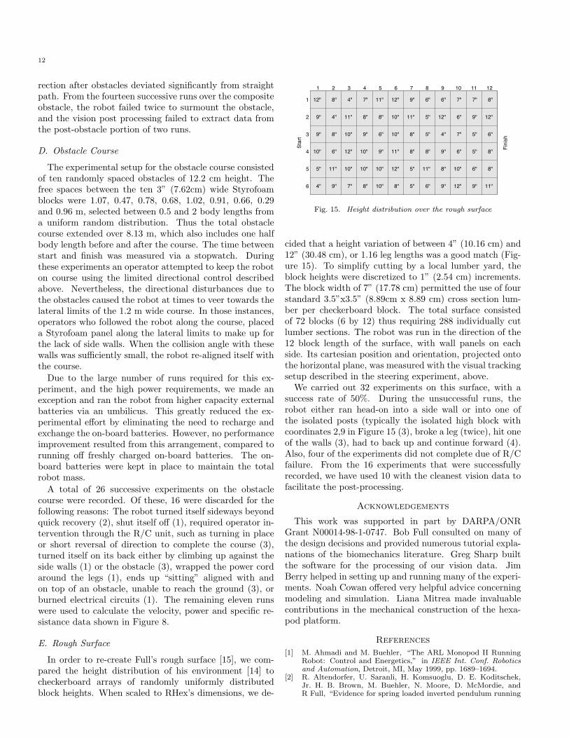
1 2 3 4 5 6 7 8 9 10 11 12
1
2
3
4
5
6
12" 8" 4" 7" 11" 12" 9" 6" 6" 7" 7" 8"
9" 4" 11" 8" 8" 10" 11" 5" 12" 6" 9" 12"
9" 8" 10" 9" 6" 10" 8" 5" 4" 7" 5" 6"
10" 6" 12" 10" 9" 11" 8" 8" 9" 6" 5" 8"
5" 11" 10" 10" 10" 12" 5" 11" 8" 10" 6" 8"
4" 9" 7" 8" 10" 8" 5" 6" 9" 12" 9" 11"
Star
t
Fini
sh
Fig. 15. Height distribution over the rough surface
cided that a height variation of between 4” (10.16 cm) and12” (30.48 cm), or 1.16 leg lengths was a good match (Fig-ure 15). To simplify cutting by a local lumber yard, theblock heights were discretized to 1” (2.54 cm) increments.The block width of 7” (17.78 cm) permitted the use of fourstandard 3.5”x3.5” (8.89cm x 8.89 cm) cross section lum-ber per checkerboard block. The total surface consistedof 72 blocks (6 by 12) thus requiring 288 individually cutlumber sections. The robot was run in the direction of the12 block length of the surface, with wall panels on eachside. Its cartesian position and orientation, projected ontothe horizontal plane, was measured with the visual trackingsetup described in the steering experiment, above.
We carried out 32 experiments on this surface, with asuccess rate of 50%. During the unsuccessful runs, therobot either ran head-on into a side wall or into one ofthe isolated posts (typically the isolated high block withcoordinates 2,9 in Figure 15 (3), broke a leg (twice), hit oneof the walls (3), had to back up and continue forward (4).Also, four of the experiments did not complete due of R/Cfailure. From the 16 experiments that were successfullyrecorded, we have used 10 with the cleanest vision data tofacilitate the post-processing.
Acknowledgements
This work was supported in part by DARPA/ONRGrant N00014-98-1-0747. Bob Full consulted on many ofthe design decisions and provided numerous tutorial expla-nations of the biomechanics literature. Greg Sharp builtthe software for the processing of our vision data. JimBerry helped in setting up and running many of the experi-ments. Noah Cowan o!ered very helpful advice concerningmodeling and simulation. Liana Mitrea made invaluablecontributions in the mechanical construction of the hexa-pod platform.
References[1] M. Ahmadi and M. Buehler, “The ARL Monopod II Running
Robot: Control and Energetics,” in IEEE Int. Conf. Roboticsand Automation, Detroit, MI, May 1999, pp. 1689–1694.
[2] R. Altendorfer, U. Saranli, H. Komsuoglu, D. E. Koditschek,Jr. H. B. Brown, M. Buehler, N. Moore, D. McMordie, andR Full, “Evidence for spring loaded inverted pendulum running

13
in a hexapod robot,” in International Symposium on Experi-mental Robotics, Hawaii, 2000.
[3] C. Angle, “Genghis: A six-legged autonomous walking robot1989, SB thesis.
[4] C. Angle, “Design of an artificial creature,” M.S. thesis, Mas-sachusetts Institute of Technology, Cambridge, MA, 1991.
[5] J. E. Bares and D. S. Wettergreen, “Dante II: Technical De-scription, results and lessons Learned,” International Journalof Robotics Research, vol. 18, no. 7, pp. 1–29, July 1999.
[6] M. Binnard, “Design of a small pneumatic walking robot,” M.S.thesis, Massachusetts Institute of Technology, Cambridge, MA,1995.
[7] R. Blickhan and R. J. Full, “Similarity in multilegged loco-motion: Bouncing like a monopode.,” Journal of ComparativePhysiology, vol. A. 173, pp. 509–517, 1993.
[8] I. E. Brown and G. E. Loeb, “A reductionist approach to creatingand using neuromusculoskeletal models,” in Biomechanics andNeural Control of Movement. Springer-Verlag, In press.
[9] M. Buehler, R. Battagila, A. Cocosco, G. Hawker, J. Sarkis, andK. Yamazaki, “SCOUT: A simple quadraped that walks, climbsand runs,” in Proceedings of the IEEE International ConferenceOn Robotics and Automation, Leuven, Belgium, May 1998, pp.1707–1712.
[10] M. Buehler, A. Cocosco, K. Yamazaki, and R. Battaglia, “Sta-ble open loop walking in quadruped robots with stick legs,” inProceedings of the IEEE International Conference On Roboticsand Automation, Detroit, Michigan, May 1999.
[11] H. J. Chiel, R. D. Beer, R. D. Quinn, and K. S. Espenchied,“Robustness of a distributed neural network controller for loco-motion in a hexapod robot,” IEEE Transactions on Roboticsand Automation, vol. 6, no. 3, pp. 293–303, 1992.
[12] J. E. Clark, J. G. Cham, S. A. Bailey, E. M. Froehlich, P. K. Na-hata, R. J. Full, and M. R. Cutkosky, “Biomimetic Design andFabrication of a Hexapedal Running Robot,” in Proceedings ofthe IEEE International Conference On Robotics and Automa-tion, Seoul, Korea, May 2001.
[13] Michael J. Coleman, Anindya Chatterjee, and Andy Ruina,“Motions of a rimless spoked wheel: a simple three-dimensionalsystem with impacts.,” Dynamics and Stability of Systems., vol.12, no. 3, pp. 139–159, 1997.
[14] R. J. Full. Personal communication.[15] R. J. Full, K. Autumn, J. I. Chung, and A. Ahn, “Rapid negoti-
ation of rough terrain by the death-head cockroach,” AmericanZoologist, vol. 38, pp. 81A, 1998.
[16] R. J. Full and D. E. Koditschek, “Templates and Anchors: Neu-romechanical Hypotheses of Legged Locomotion on Land,” Jour-nal of Experimental Biology, vol. 202, pp. 3325–3332, 1999.
[17] G. Gabrielli and T. H. von Karman, “What price speed?,” Me-chanical Engineering, vol. 72, no. 10, pp. 775–781, 1950.
[18] H. Goldstein, Classical Mechnanics, Addison-Wesley, 1980.[19] P. Gregorio, M. Ahmadi, and M. Buehler, “Design, control and
energetics of an electrically actuated legged robot,” IEEE Trans.Systems, Man, and Cybernetics, vol. 27, no. 4, pp. 626–634, Aug1997.
[20] H. G. Grimm Animated Toy, US Patent 2,827,735; 1958.[21] S. Hirose, “A study of design and control of a quadruped walking
machine.,” International Journal of Robotics Research, vol. 3,no. 2, pp. 113–133, 1984.
[22] E. R. Honeywell Walking Tractor, US Patent 1,375,752; 1920.[23] M. Z. Huang and K. J. Waldron, “Relationship between payload
and speed in legged locomotion systems,” IEEE Transactionson Robotics and Automation, vol. 6, no. 5, pp. 570–577, October1990.
[24] Interelectric AG, Sachseln, Switzerland, Maxon Motor Catalog,1997/98, www.maxon.com.
[25] T. M. Kubow and R. J. Full, “The role of the mechanical sys-tem in control: A hypothesis of self-stabilization in hexapedalrunners,” Phil. Trans. R. Soc. Lond., vol. B. 354, pp. 849–862,1999.
[26] Mattel’s Major Matt Mason’s #6304 Space Crawlerhttp://www.wildtoys.com/MMMPage/MattelPlaysets/mmm3part1.html.
[27] NSF Institute for Mathematics and Its Applications Spring 1998Workshop on Animal Locomotion and Robotics. June 1-5 1998,http://www.ima.umn.edu/dynsys/spring/dynsys10.html.
[28] D. Papadopoulos and M. Buehler, “Stable running in aquadruped robot with compliant legs,” in Proceedings of theIEEE International Conference On Robotics and Automation,San Francisco, CA, April 2000.
[29] D. R. Pugh, E. A. Ribble, V. J. Vohnout, T. E. Bihari, T. M.Walliser, M. R. Patterson, and K. J. Waldron, “Technical de-scription of the adaptive suspension vehicle,” InternationalJournal of Robotics Research, vol. 9, no. 2, pp. 24–42, April1990.
[30] M. H. Raibert, Legged robots that balance, MIT Press, Cam-bridge MA, 1986.
[31] U. Saranli, SimSect Programmer’s Manual, The University ofMichigan, 1999, In preparation.
[32] U. Saranli, W. J. Schwind, and D. E. Koditschek, “Toward theControl of a Multi-Jointed, Monoped Runner,” in Proceedings ofthe IEEE International Conference On Robotics and Automa-tion, Leuven, Belgium, May 1998, vol. 3, pp. 2676–82.
[33] J. Schmitt and P. Holmes, “Mechanical models for insect lo-comotion I: Dynamics and stability in the horizontal plane.,”Biological Cybernetics, vol. submitted, 1999.
[34] W. J. Schwind and D. E. Koditschek, “Approximating the stancemap of a 2-dof monoped runner,” Journal of Nonlinear Science,vol. 10, pp. 533–568, 2000.
[35] K. J. Waldron and V. J. Vohnout, “Configuration design ofthe Adaptive Suspension Vehicle.,” International Journal ofRobotics Research, vol. 3, no. 2, pp. 37–48, 1984.


![FLUID POWER/POWER TRANSMISSION High Frequency Hexapod Testing · [] High Frequency Hexapod Testing C ontrol refinements to a six degree of freedom hydraulic hexapod used for automobile](https://img.dokumen.tips/doc/110x75/5b3facbc7f8b9a4b3f8c68da/fluid-powerpower-transmission-high-frequency-hexapod-high-frequency-hexapod.jpg)